ZyXEL Communications P660HWTX 802.11g Wireless ADSL2+4 port Gateway User Manual 1
ZyXEL Communications Corporation 802.11g Wireless ADSL2+4 port Gateway Users Manual 1
Contents
- 1. Users Manual 1
- 2. Users Manual 2
- 3. Users Manual 3
- 4. Users Manual 4
Users Manual 1

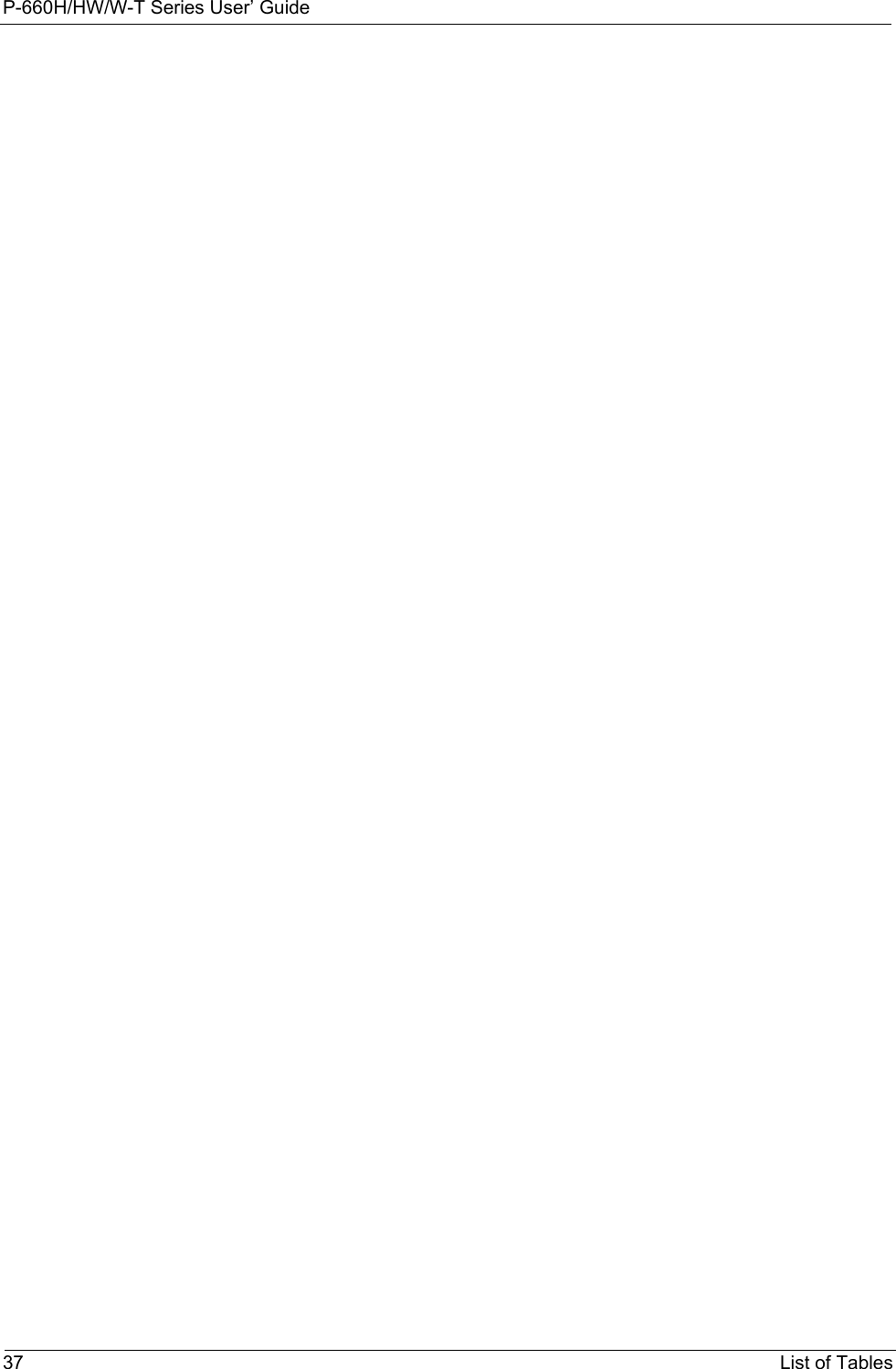
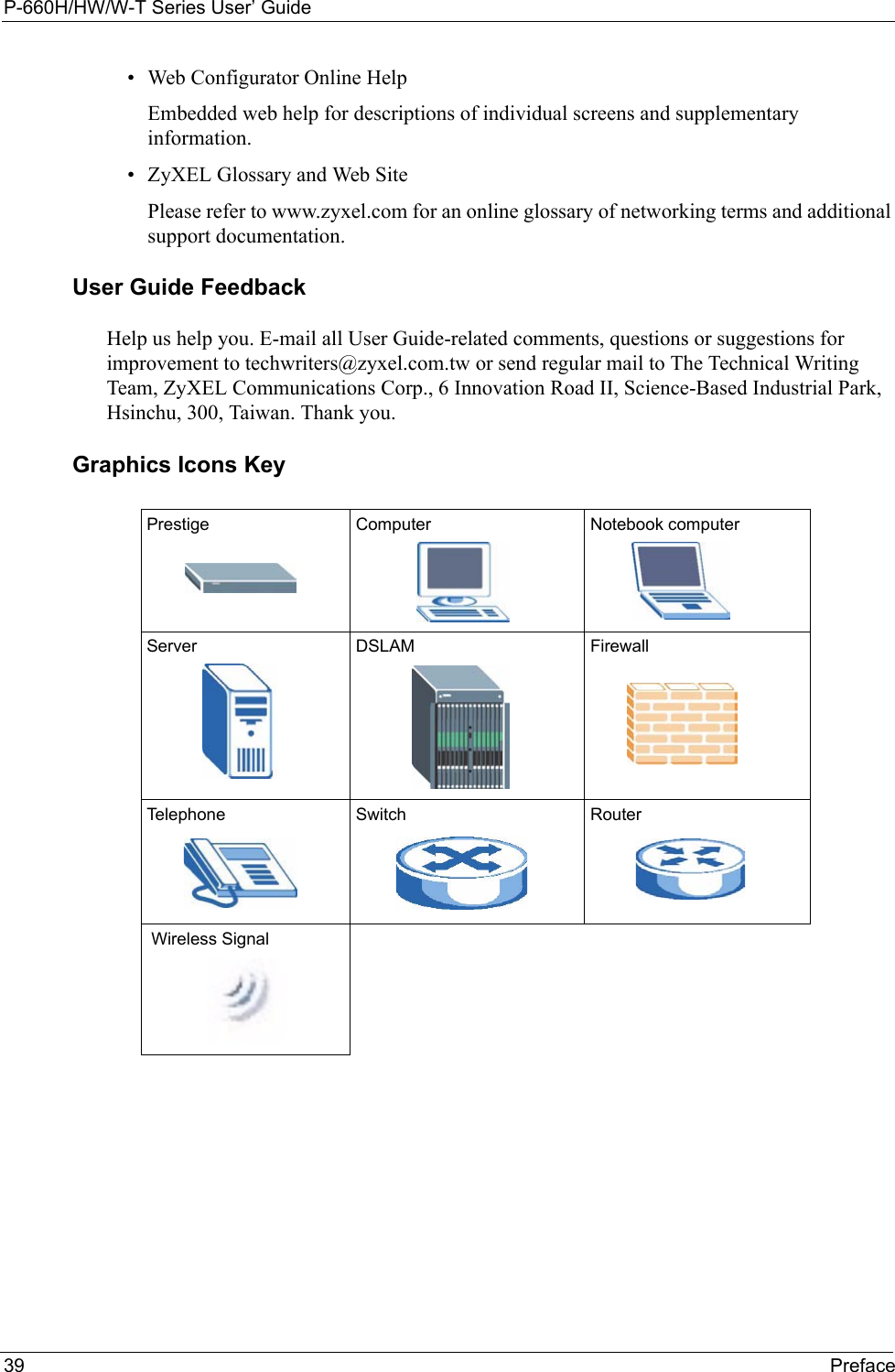
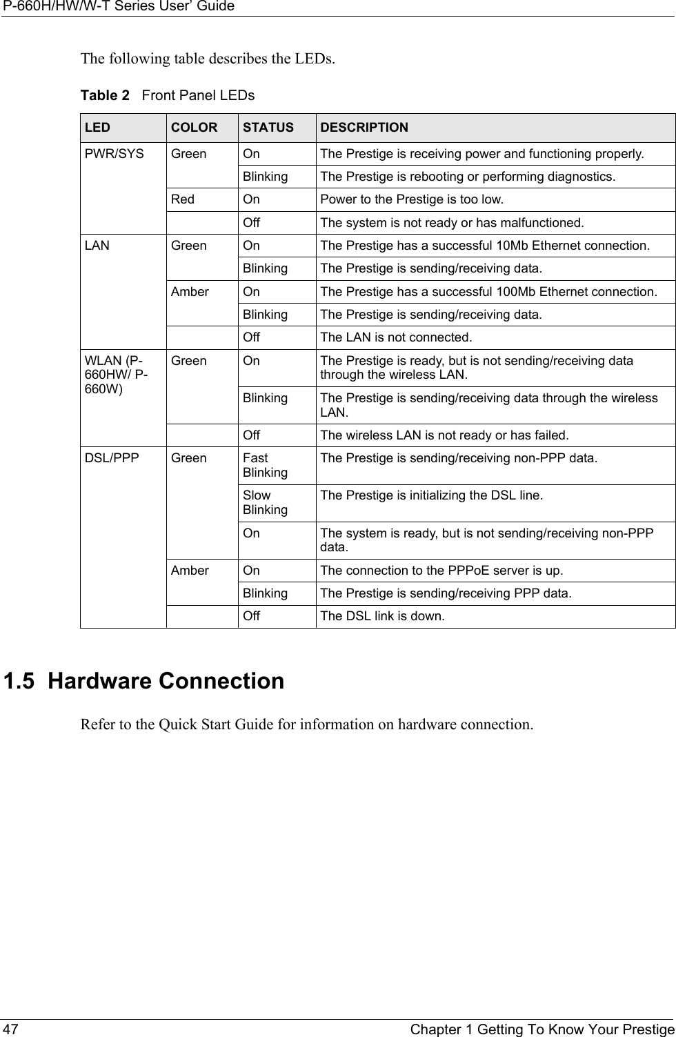
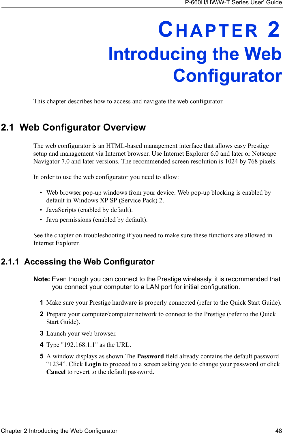
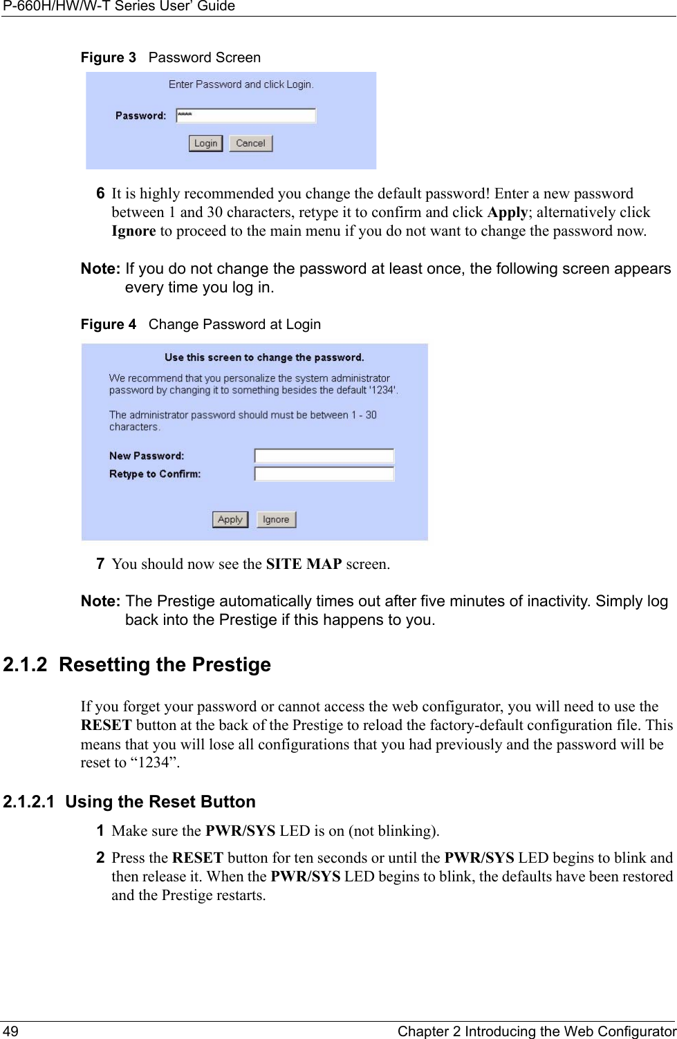
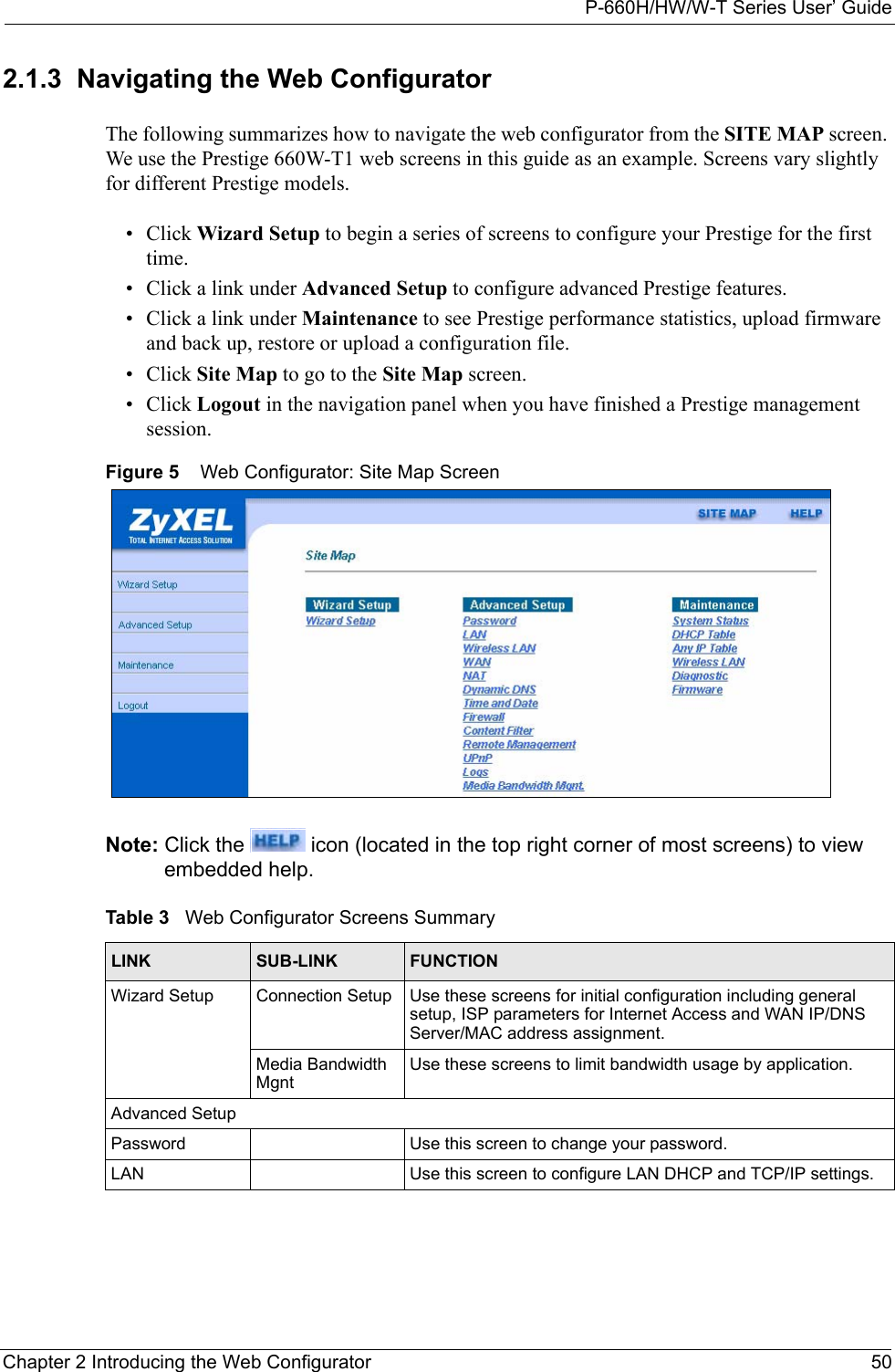
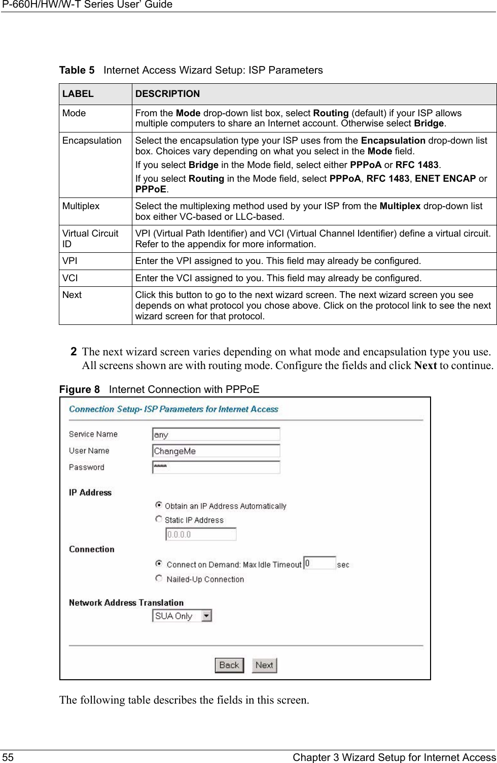
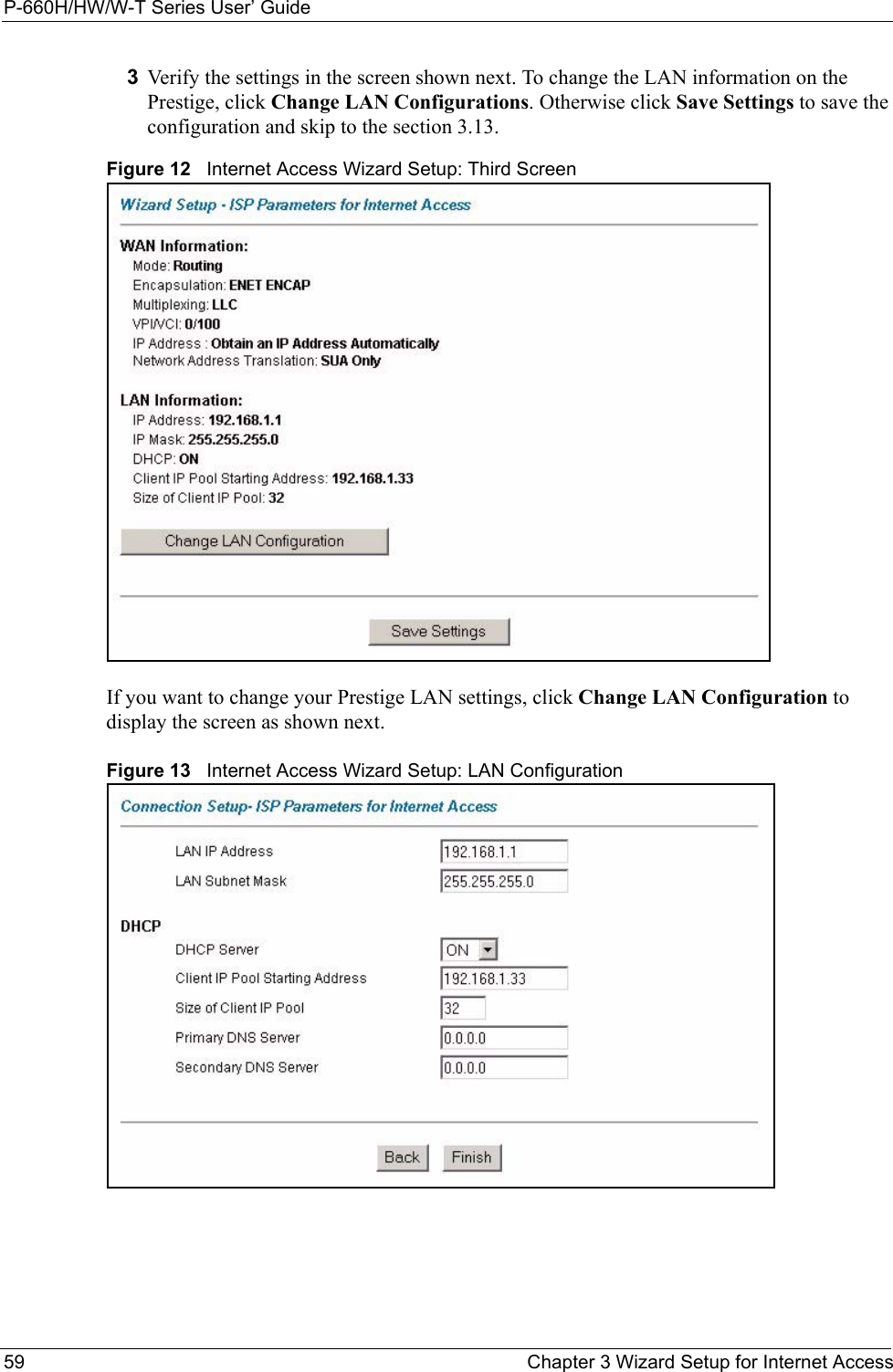
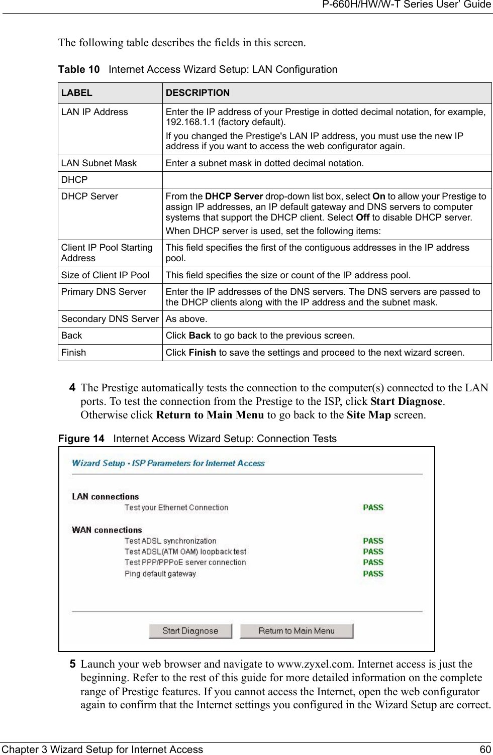
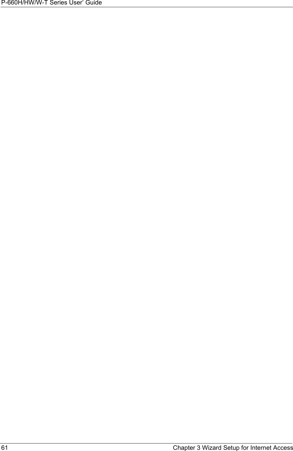
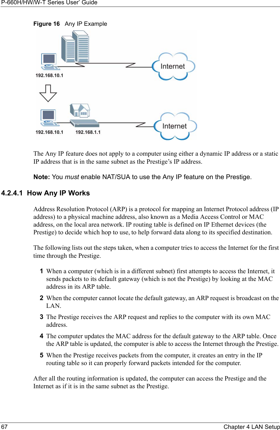
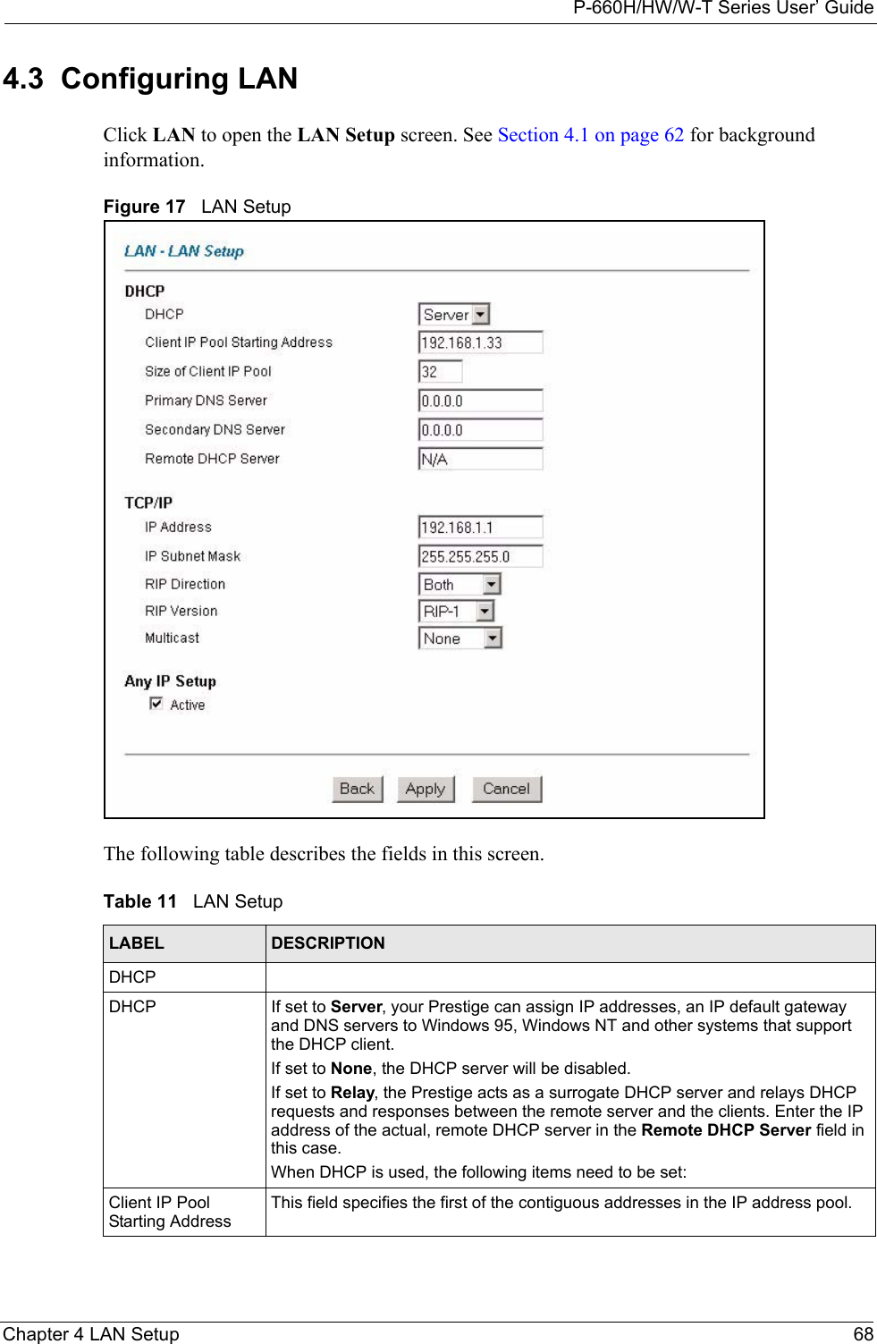
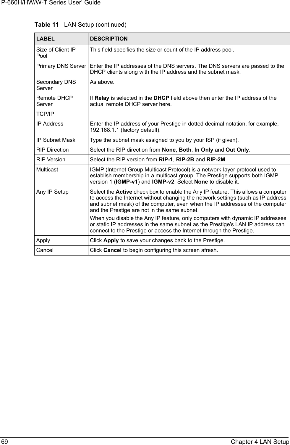
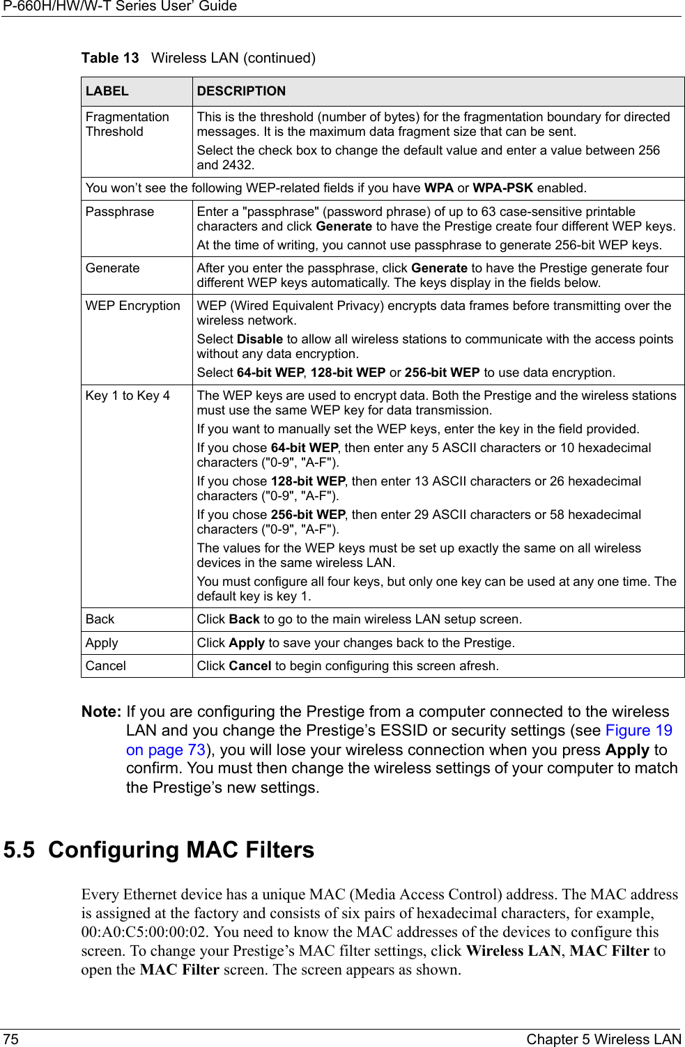
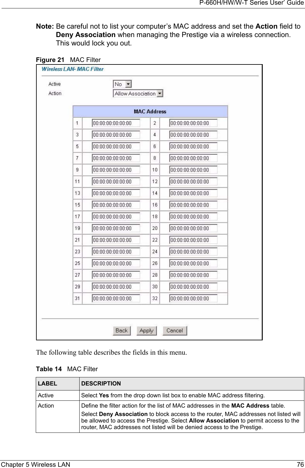
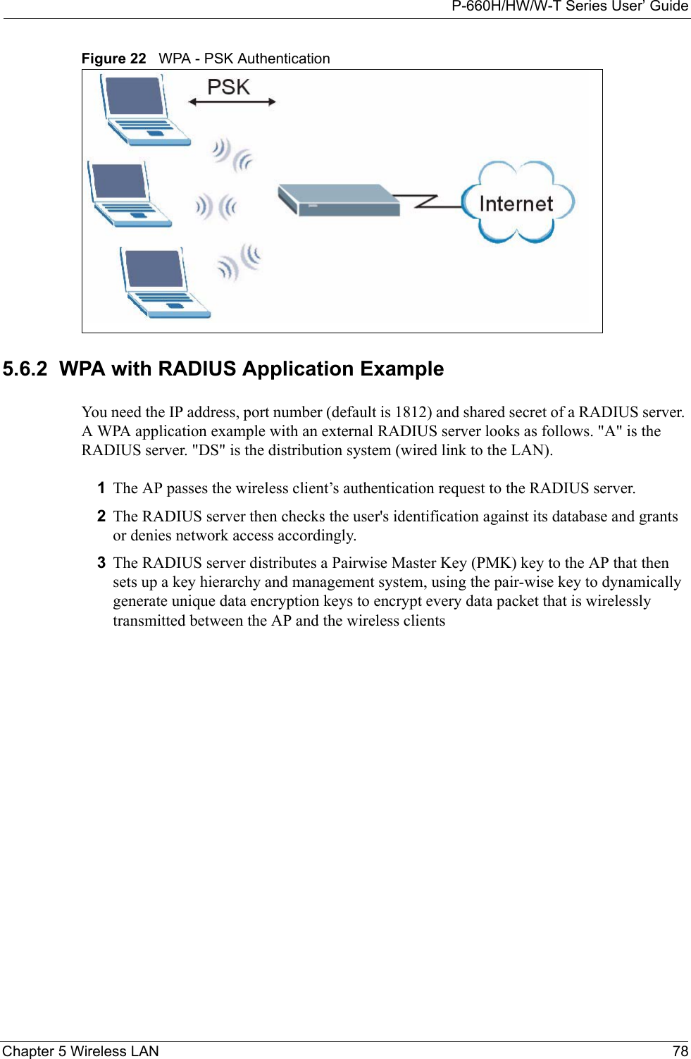
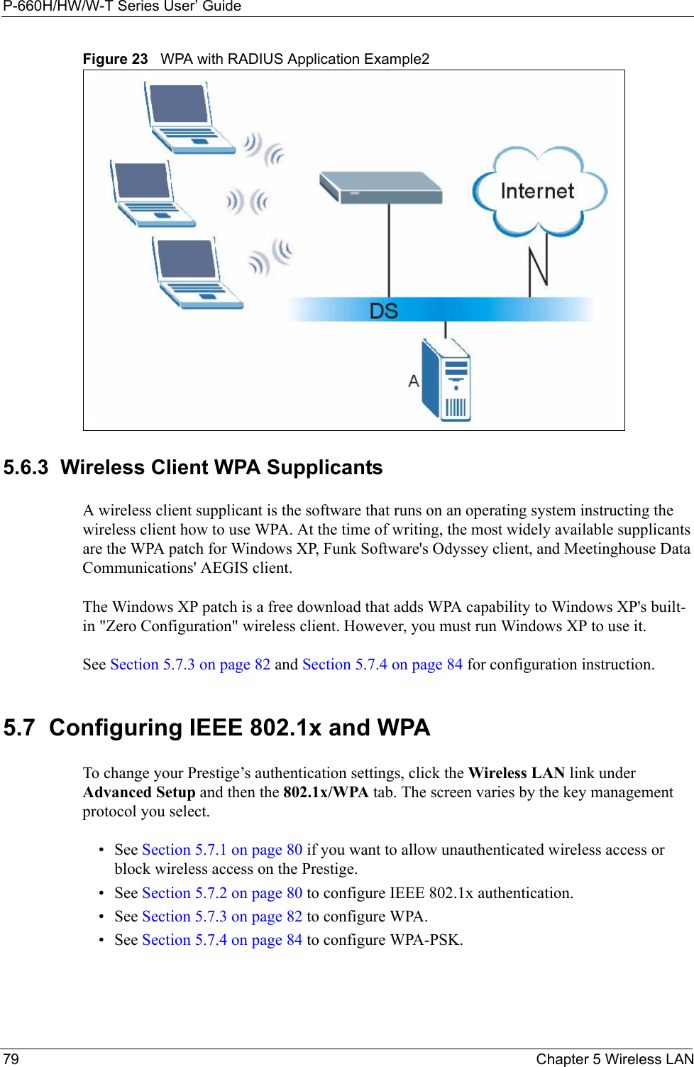
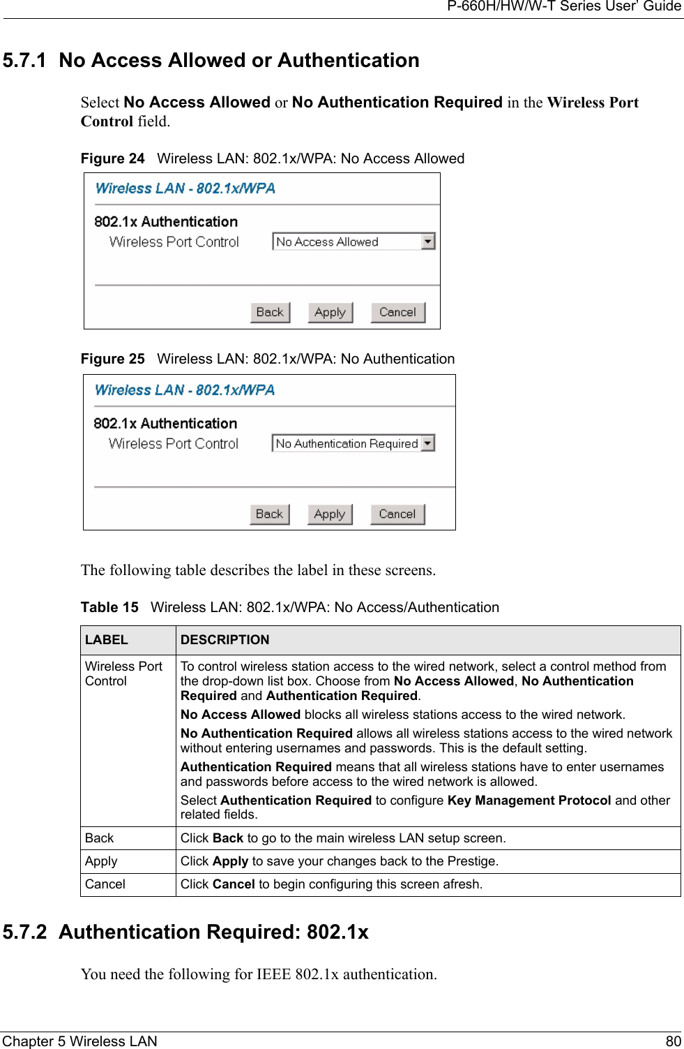
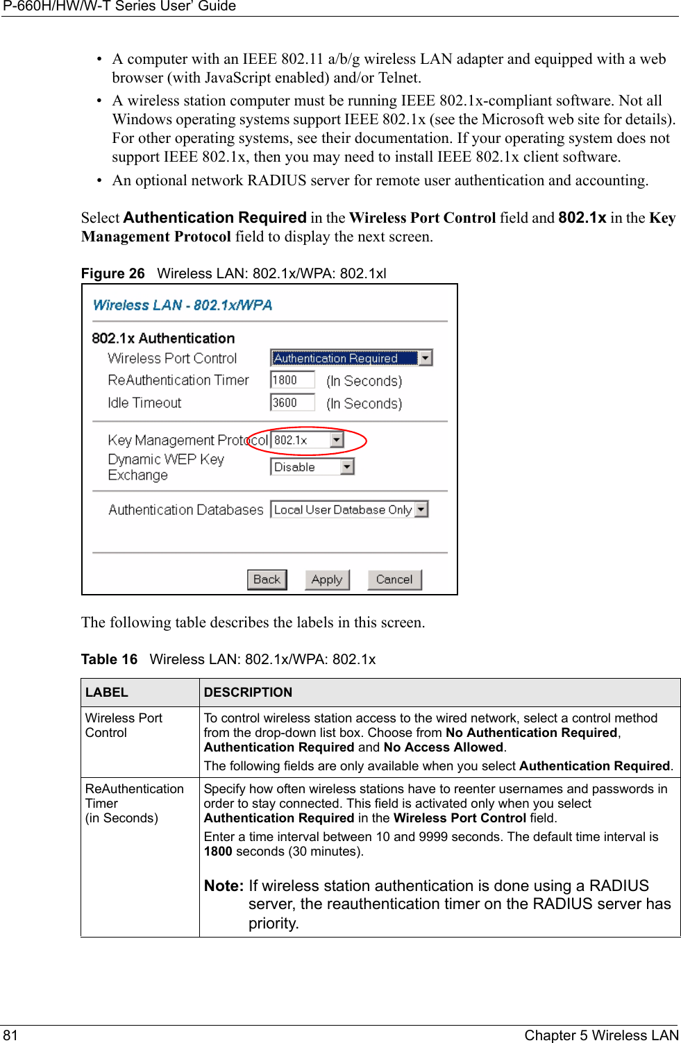
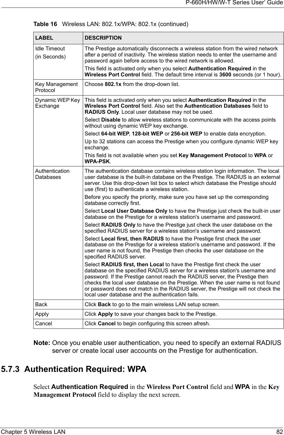
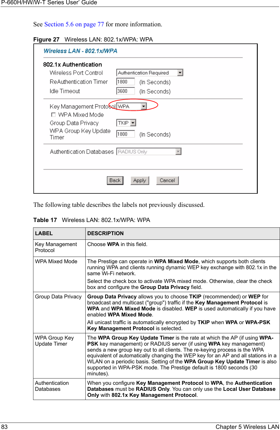
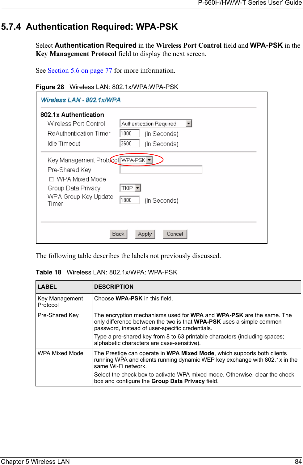
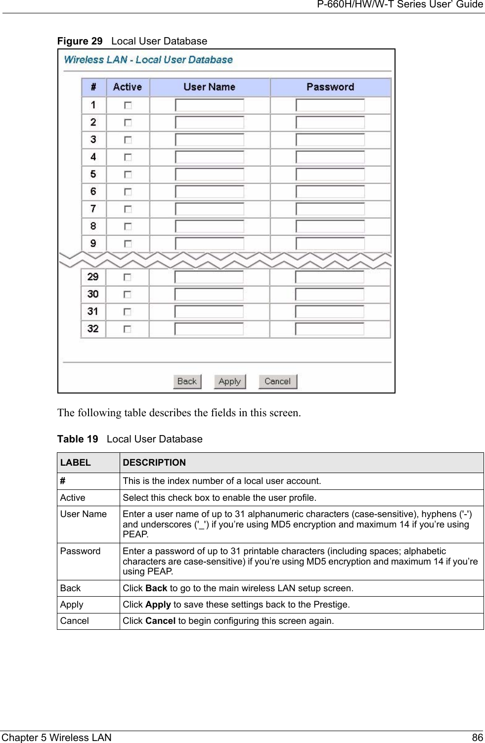
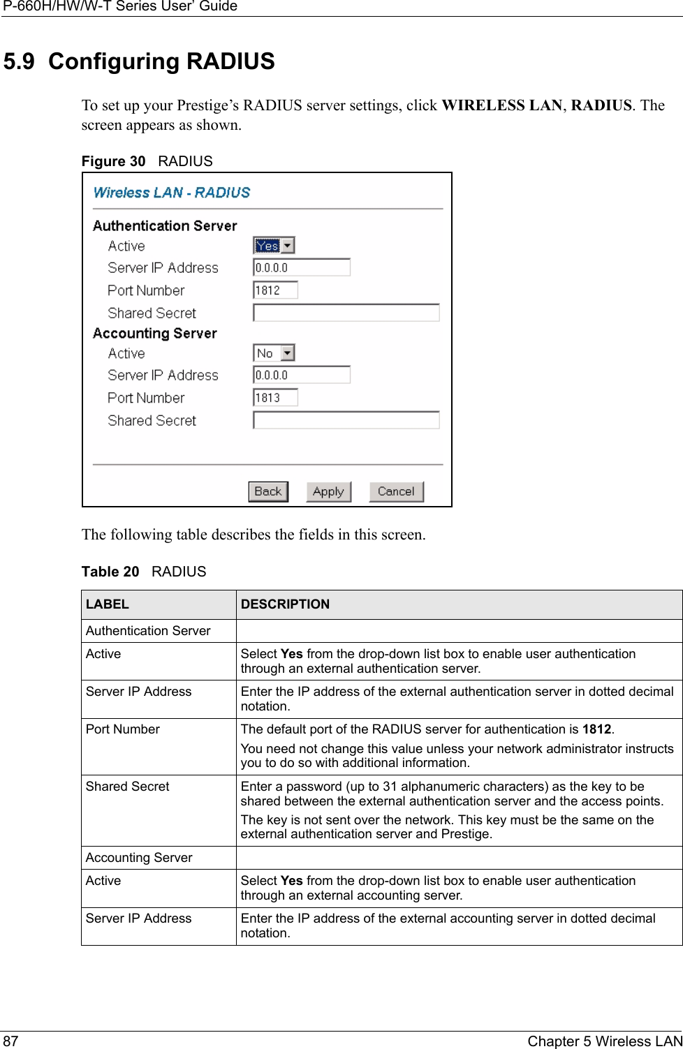
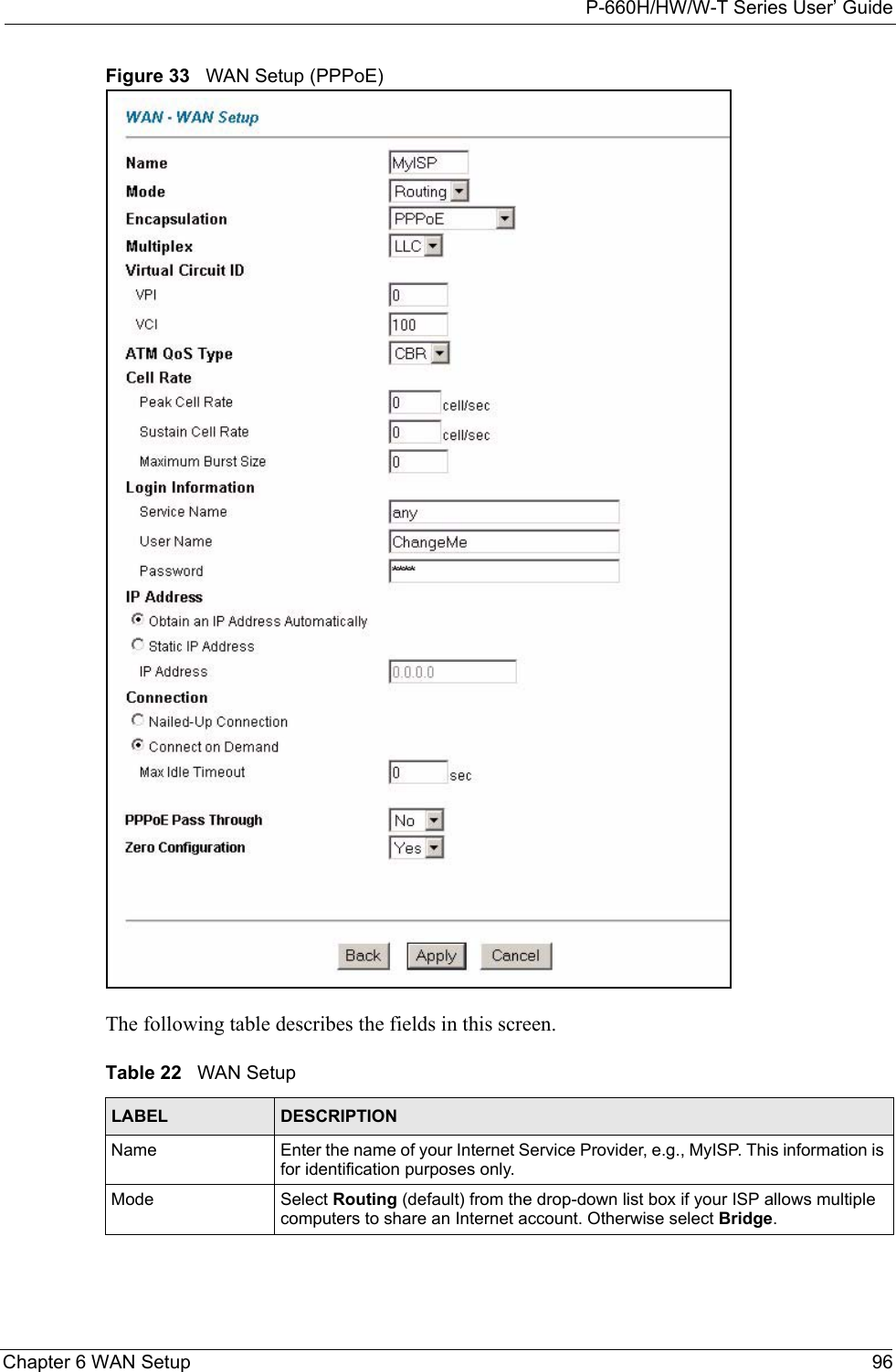
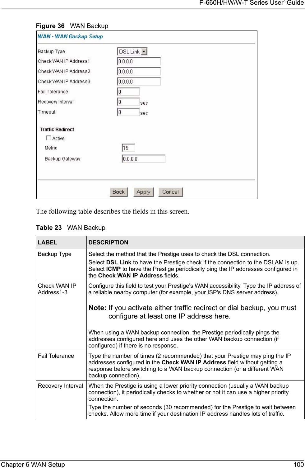
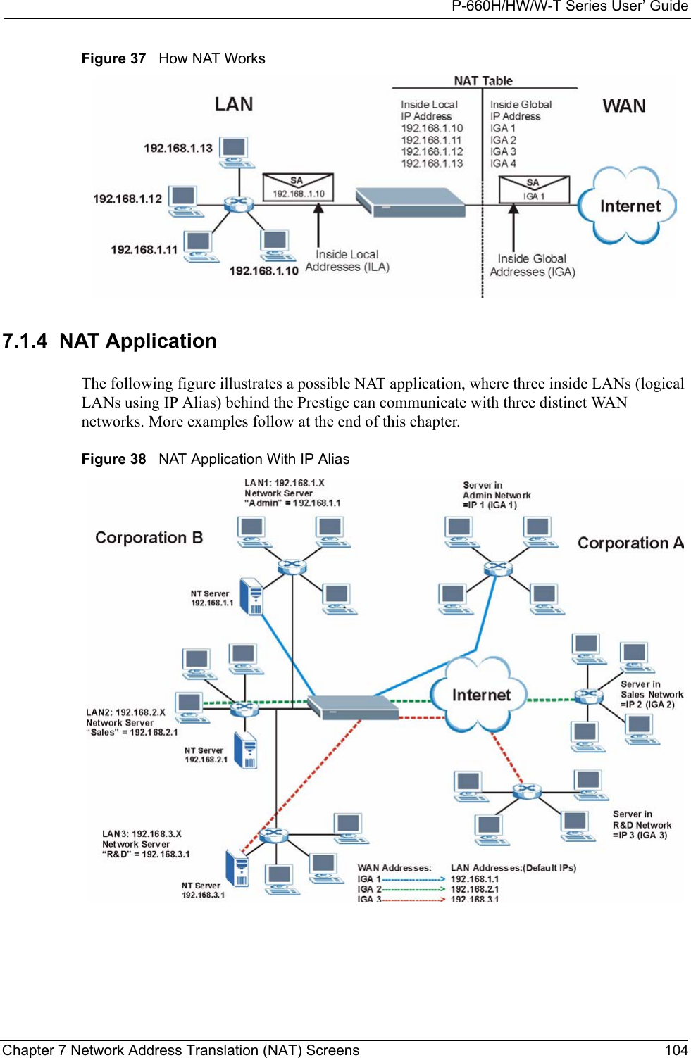
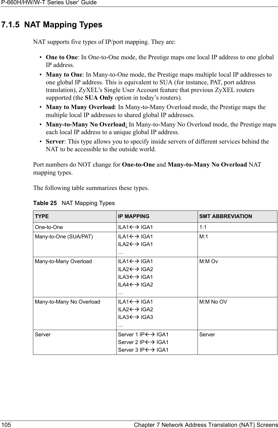
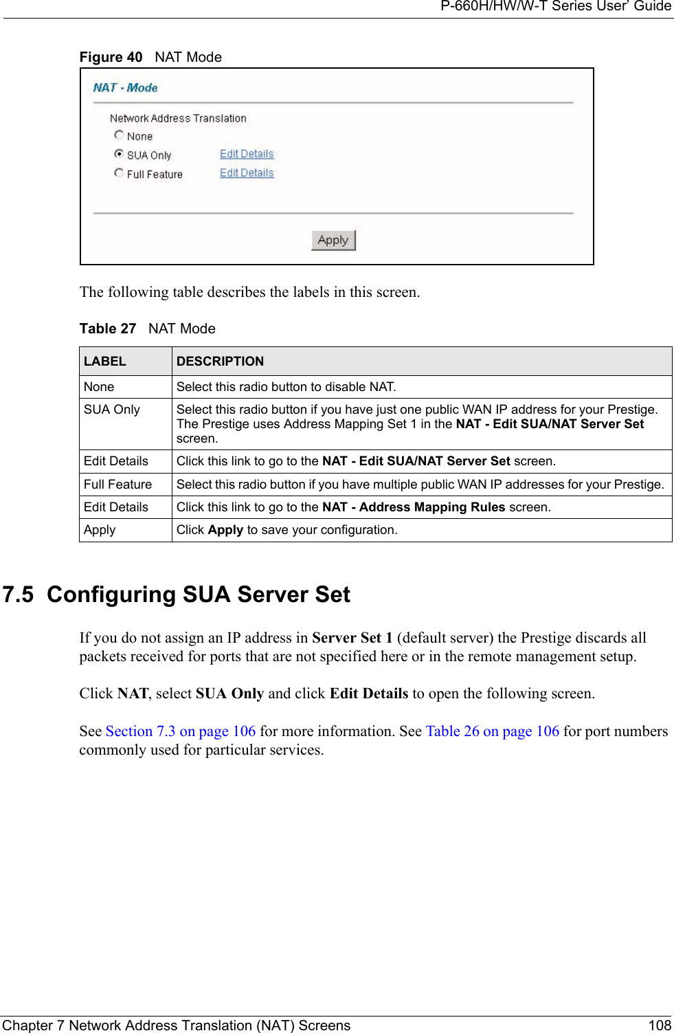
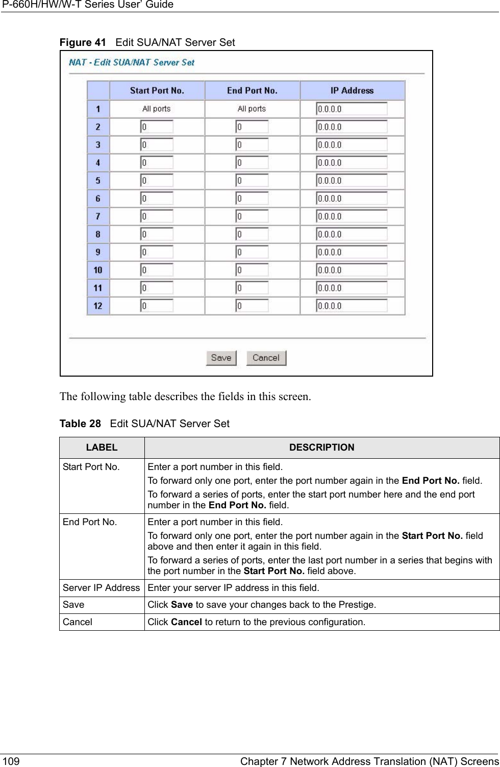
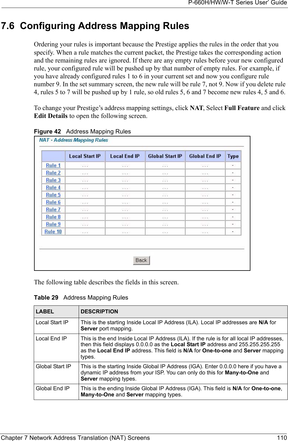
![P-660H/HW/W-T Series User’ GuidePreface 38PrefaceCongratulations on your purchase of the P-660H/HW/W T series ADSL 2+ gateway. P-660W and P-660HW come with biult-in IEEE 802.11g wireless capability allowing wireless connectivity. P-660H and P-660HW have a 4-port switch that allows you to connect up to 4 computers to the Prestige without purchasing a switch/hub. Note: Register your product online to receive e-mail notices of firmware upgrades and information at www.zyxel.com for global products, or at www.us.zyxel.com for North American products.About This User's GuideThis manual is designed to guide you through the configuration of your Prestige for its various applications. The web configurator parts of this guide contain background information on features configurable by web configurator. The SMT parts of this guide contain background information solely on features not configurable by web configurator.Note: Use the web configurator, System Management Terminal (SMT) or command interpreter interface to configure your Prestige. Not all features can be configured through all interfaces.Syntax Conventions• “Enter” means for you to type one or more characters. “Select” or “Choose” means for you to use one predefined choices.• The SMT menu titles and labels are in Bold Times New Roman font. Predefined field choices are in Bold Arial font. Command and arrow keys are enclosed in square brackets. [ENTER] means the Enter, or carriage return key; [ESC] means the Escape key and [SPACE BAR] means the Space Bar.• Mouse action sequences are denoted using a comma. For example, “click the Apple icon, Control Panels and then Modem” means first click the Apple icon, then point your mouse pointer to Control Panels and then click Modem.• For brevity’s sake, we will use “e.g.,” as a shorthand for “for instance”, and “i.e.,” for “that is” or “in other words” throughout this manual.• The P-600H/HW/W T series may be referred to as the “Prestige” in this User’s Guide. • Application graphics and screen shoots shown are for the P-660W model unless otherwise specified. Related Documentation• Supporting DiskRefer to the included CD for support documents.• Quick Start Guide The Quick Start Guide is designed to help you get up and running right away. They contain connection information and instructions on getting started.](https://usermanual.wiki/ZyXEL-Communications/P660HWTX.Users-Manual-1/User-Guide-566050-Page-38.png)