ZyXEL Communications P660HWTX 802.11g Wireless ADSL2+4 port Gateway User Manual 4
ZyXEL Communications Corporation 802.11g Wireless ADSL2+4 port Gateway Users Manual 4
Contents
- 1. Users Manual 1
- 2. Users Manual 2
- 3. Users Manual 3
- 4. Users Manual 4
Users Manual 4
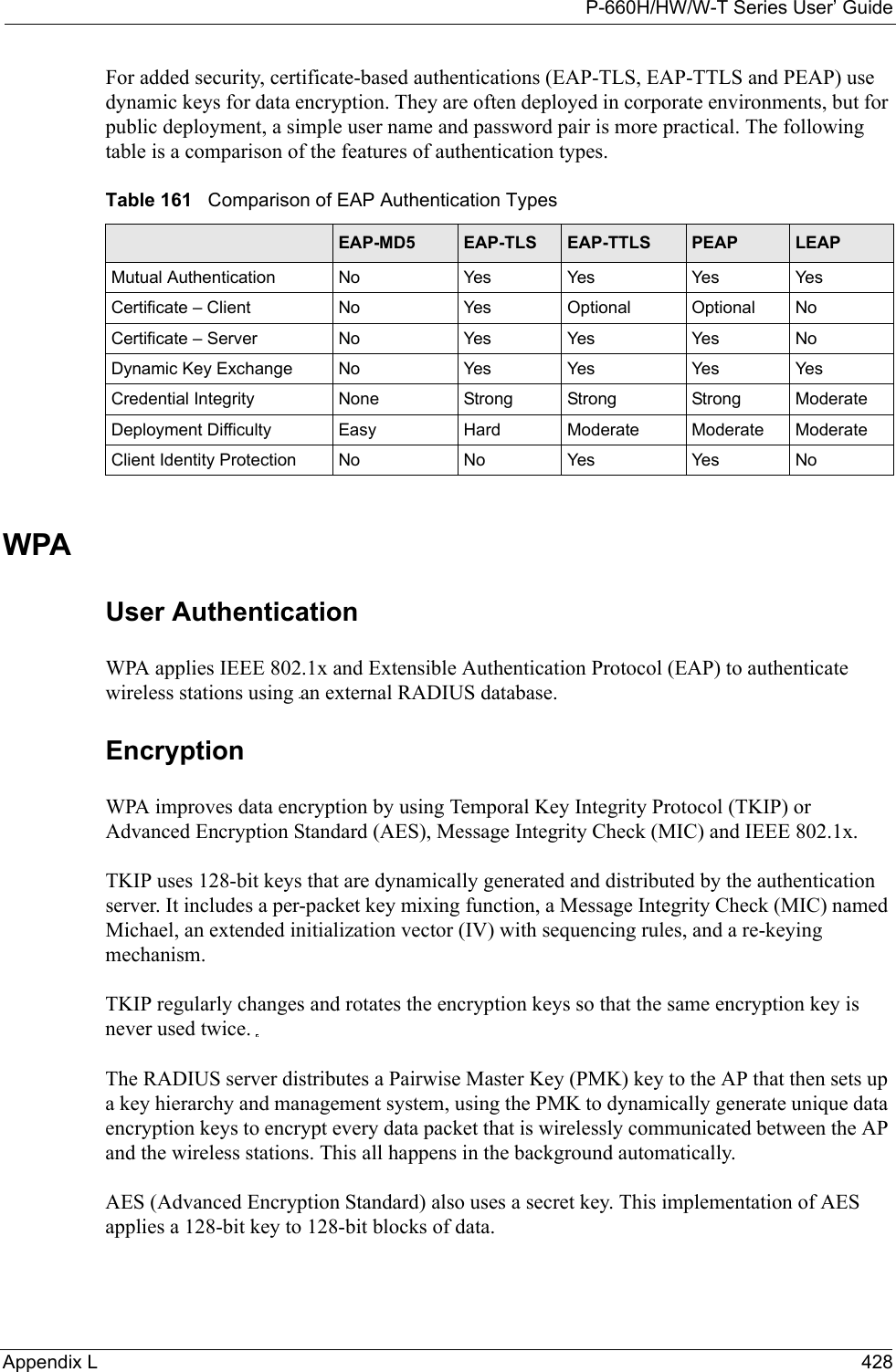
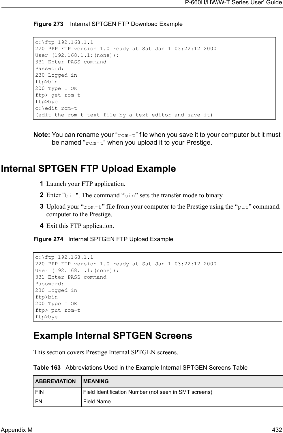
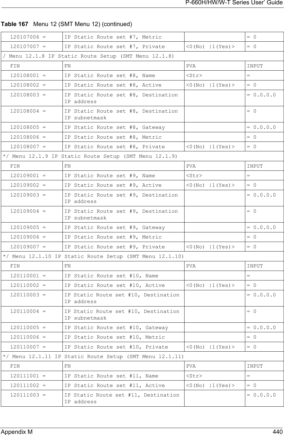
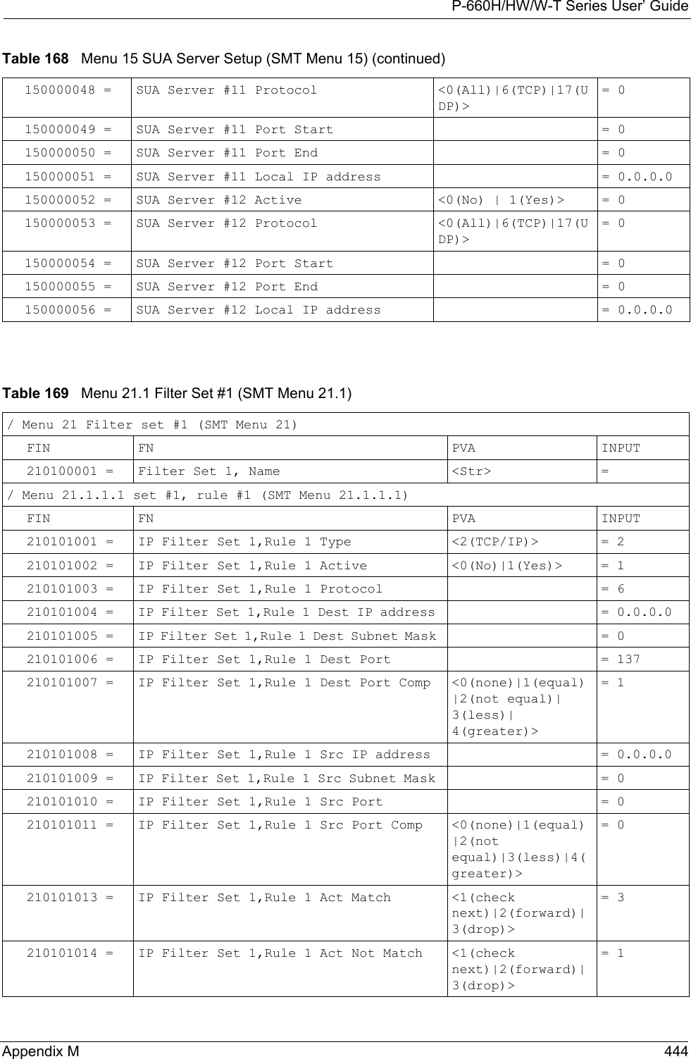
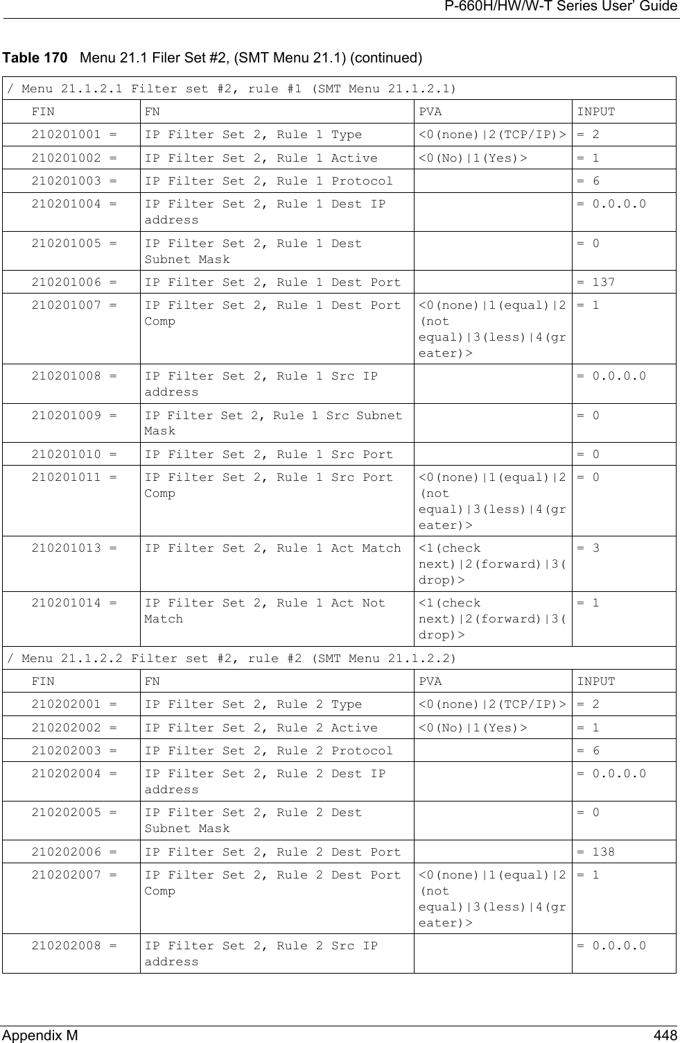
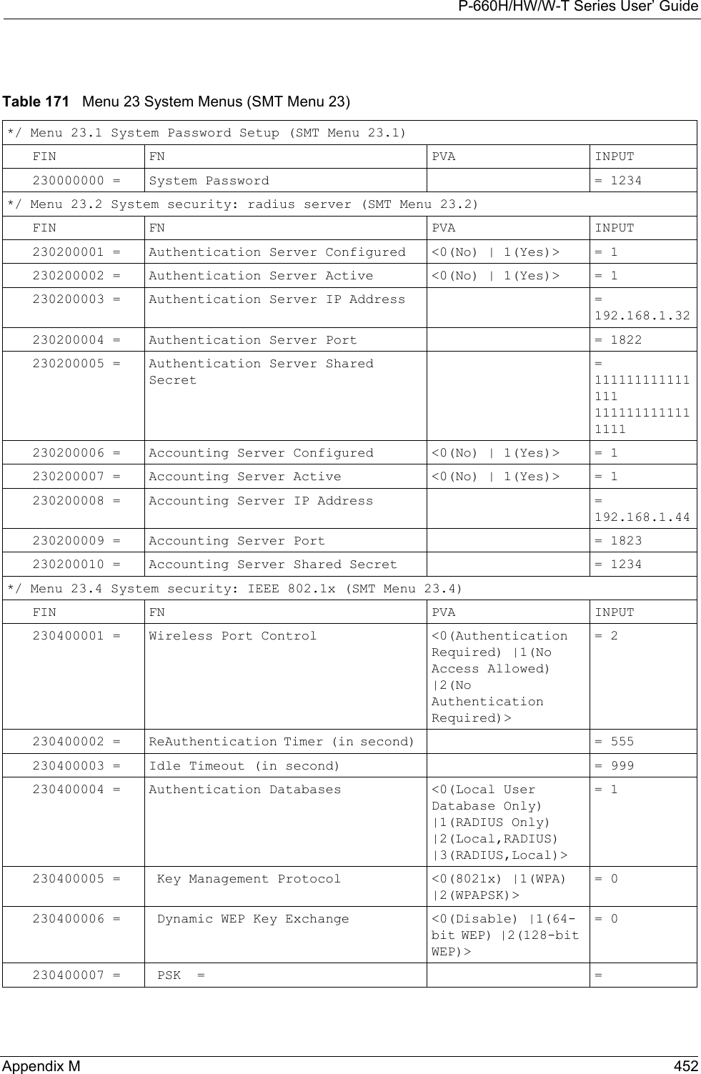
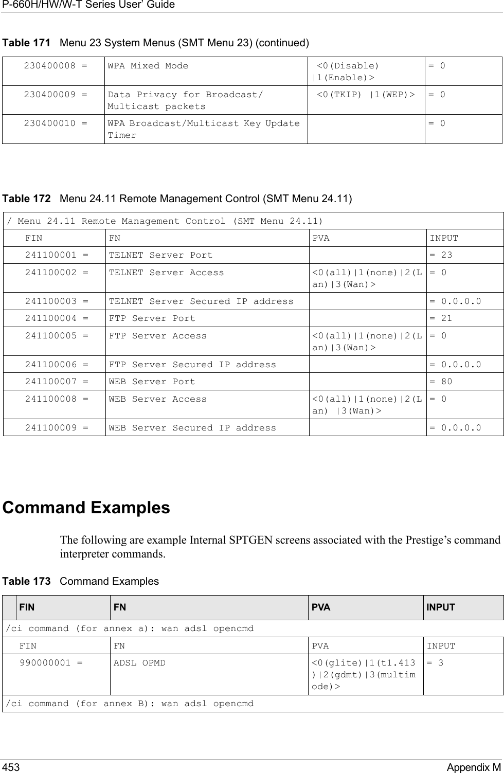
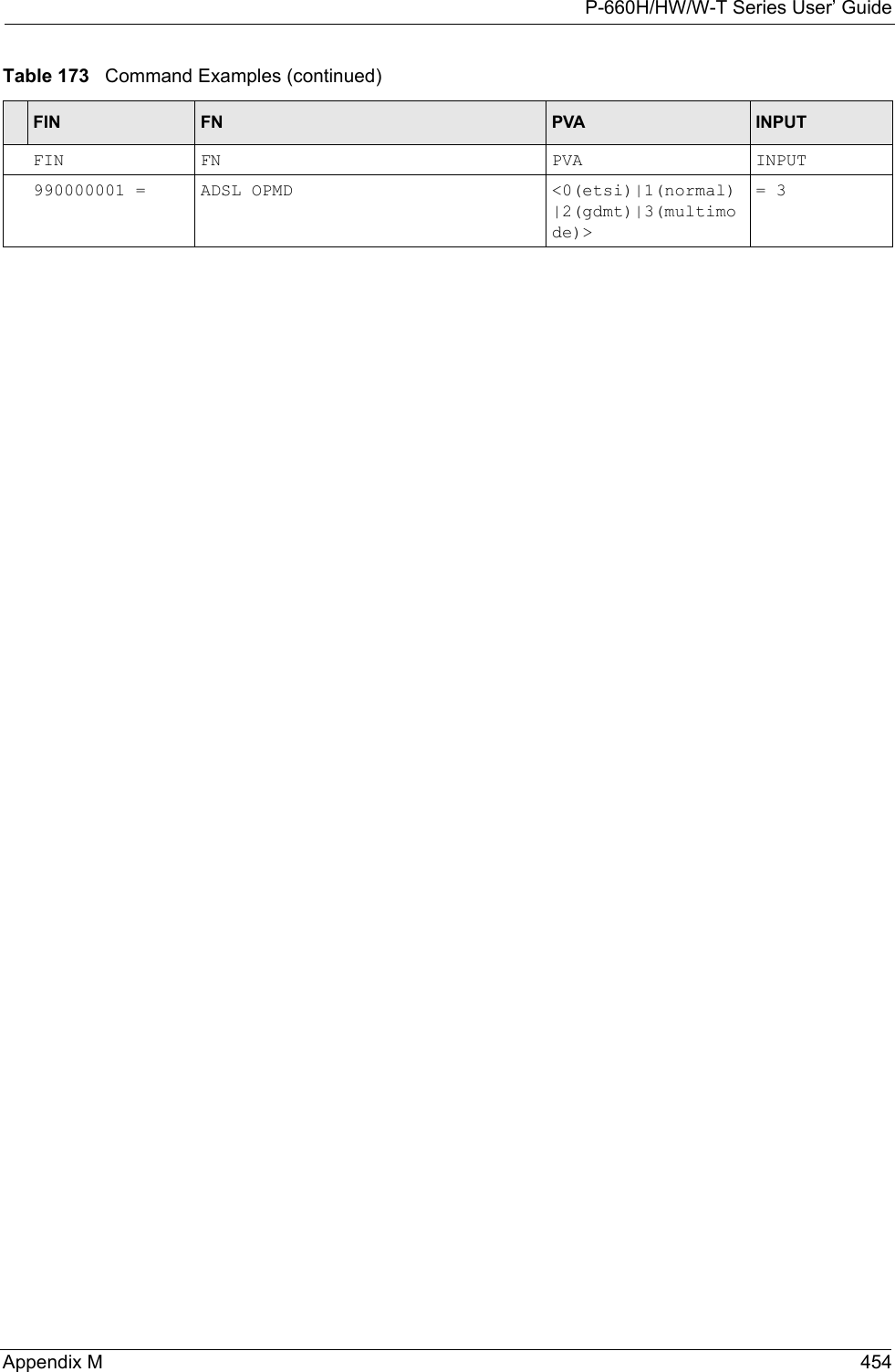
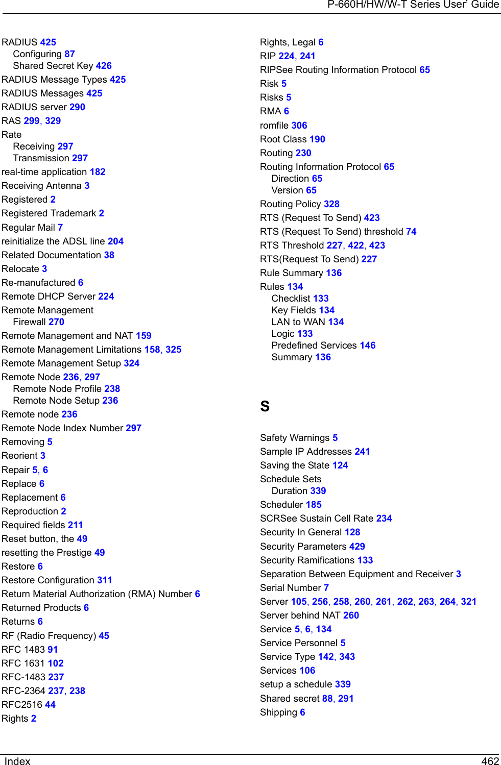
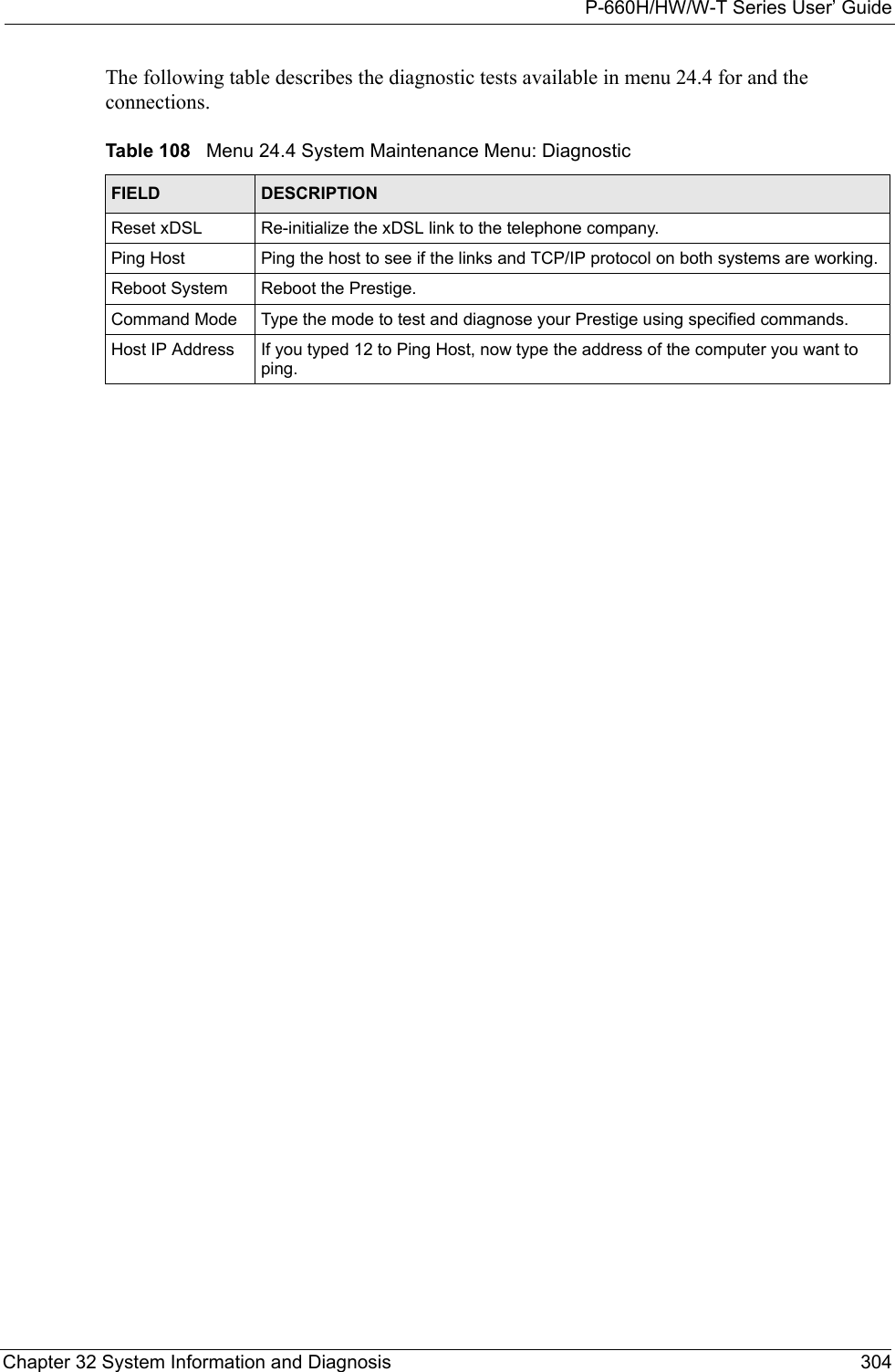
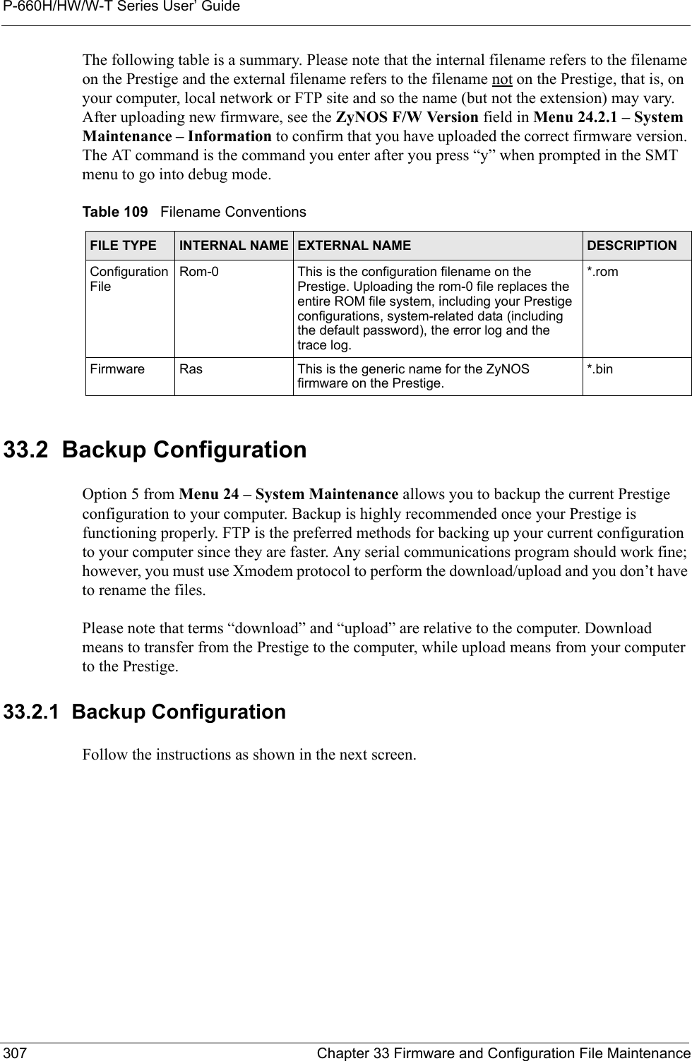
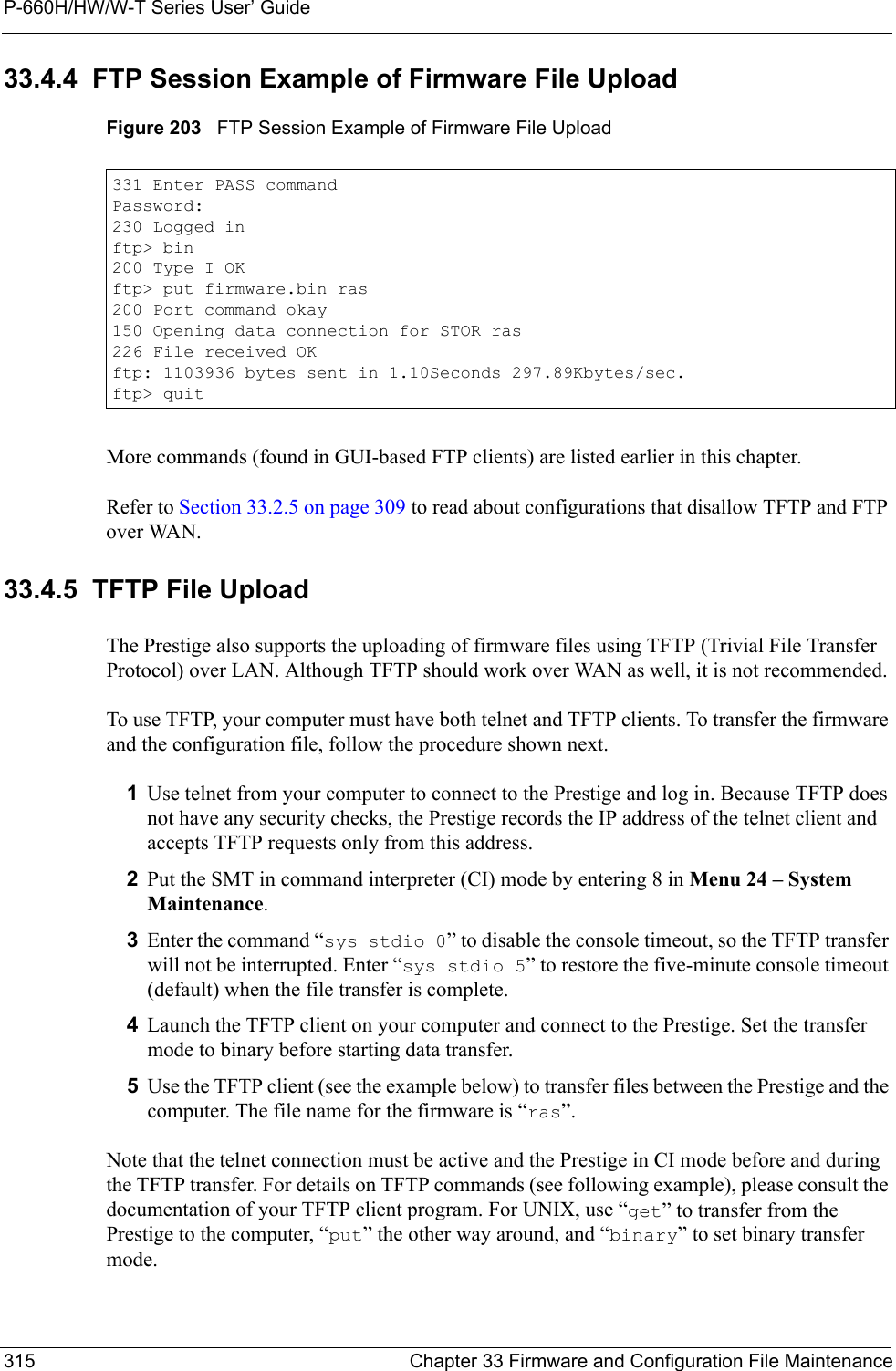
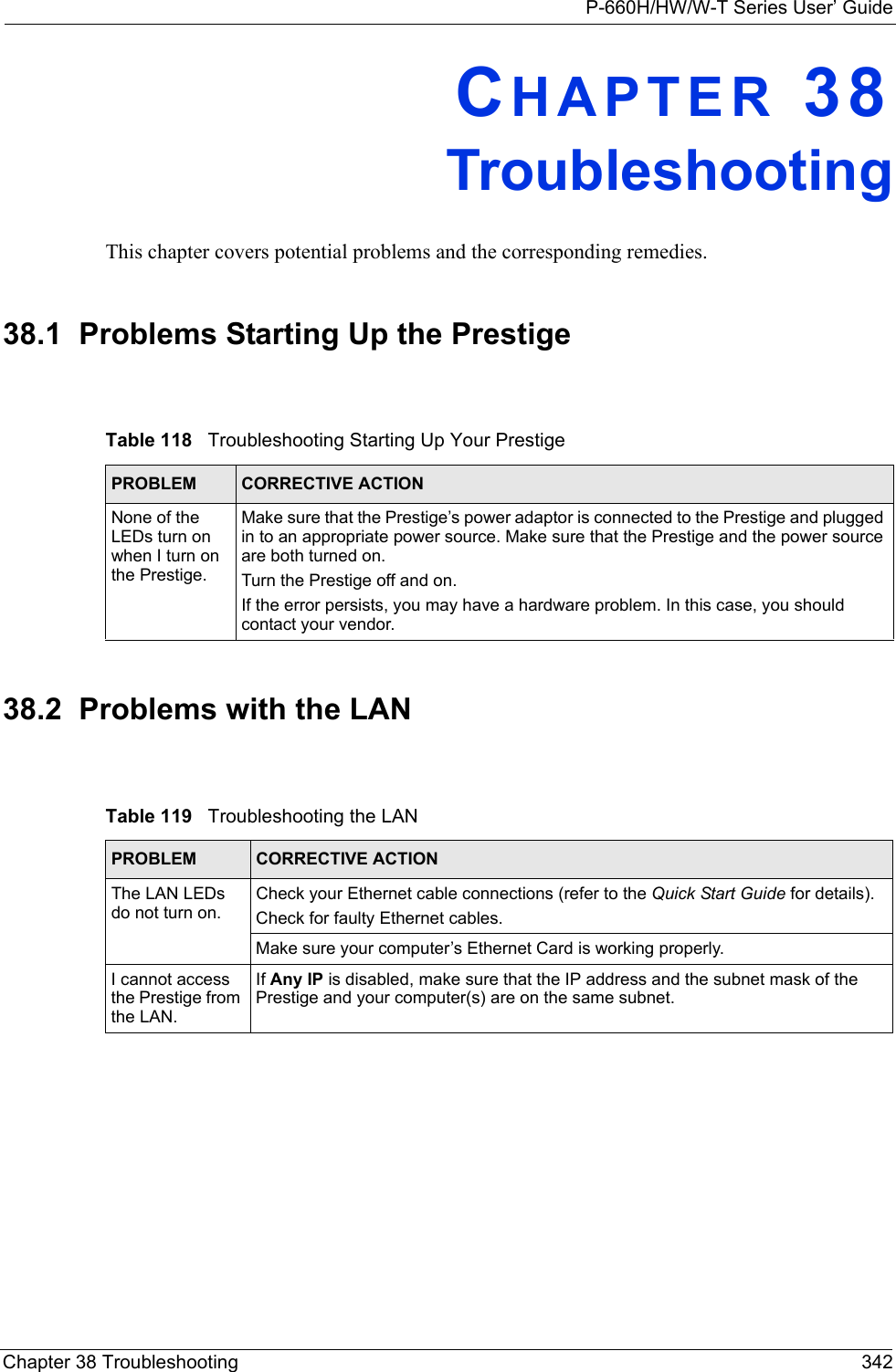
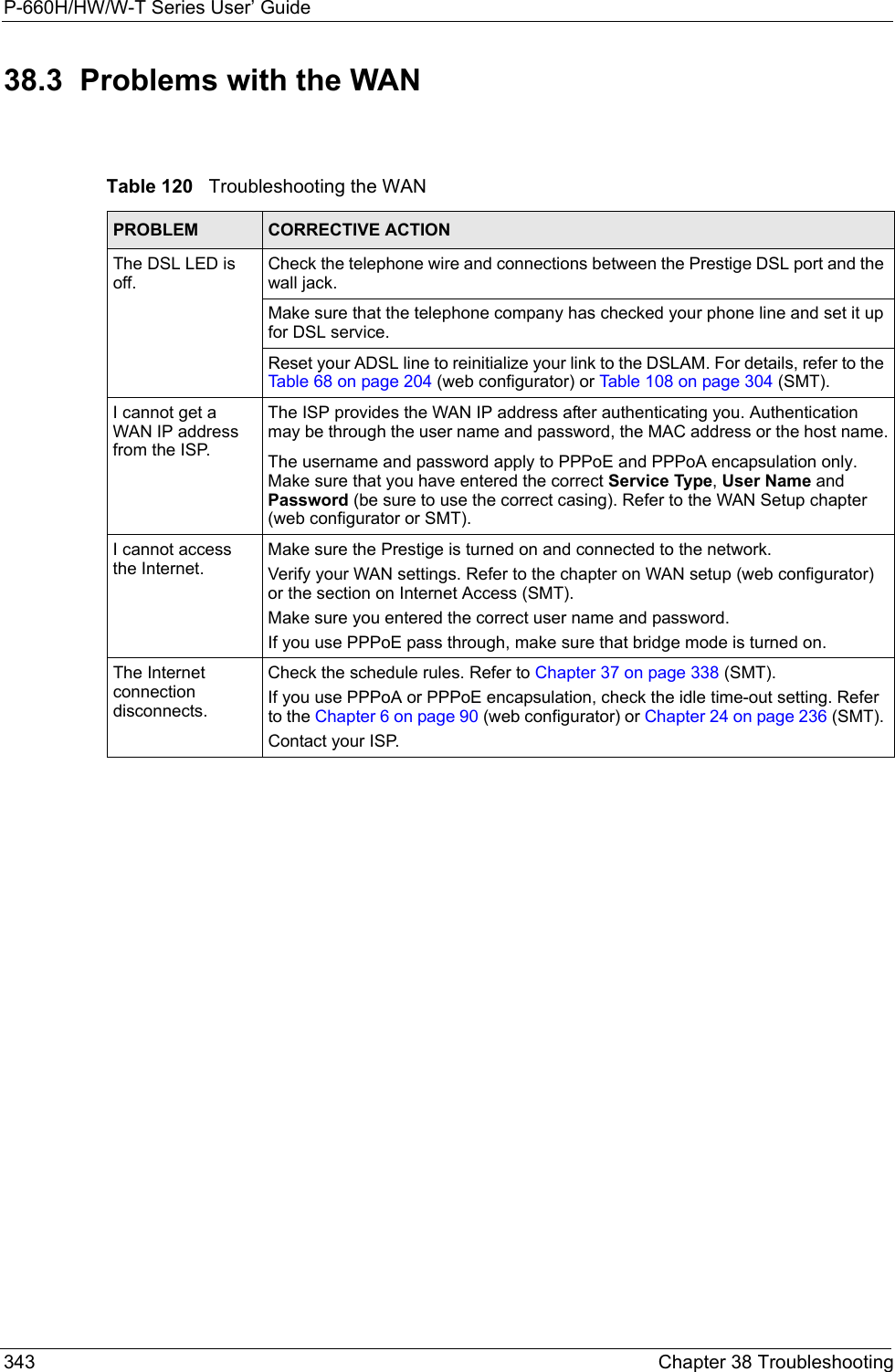
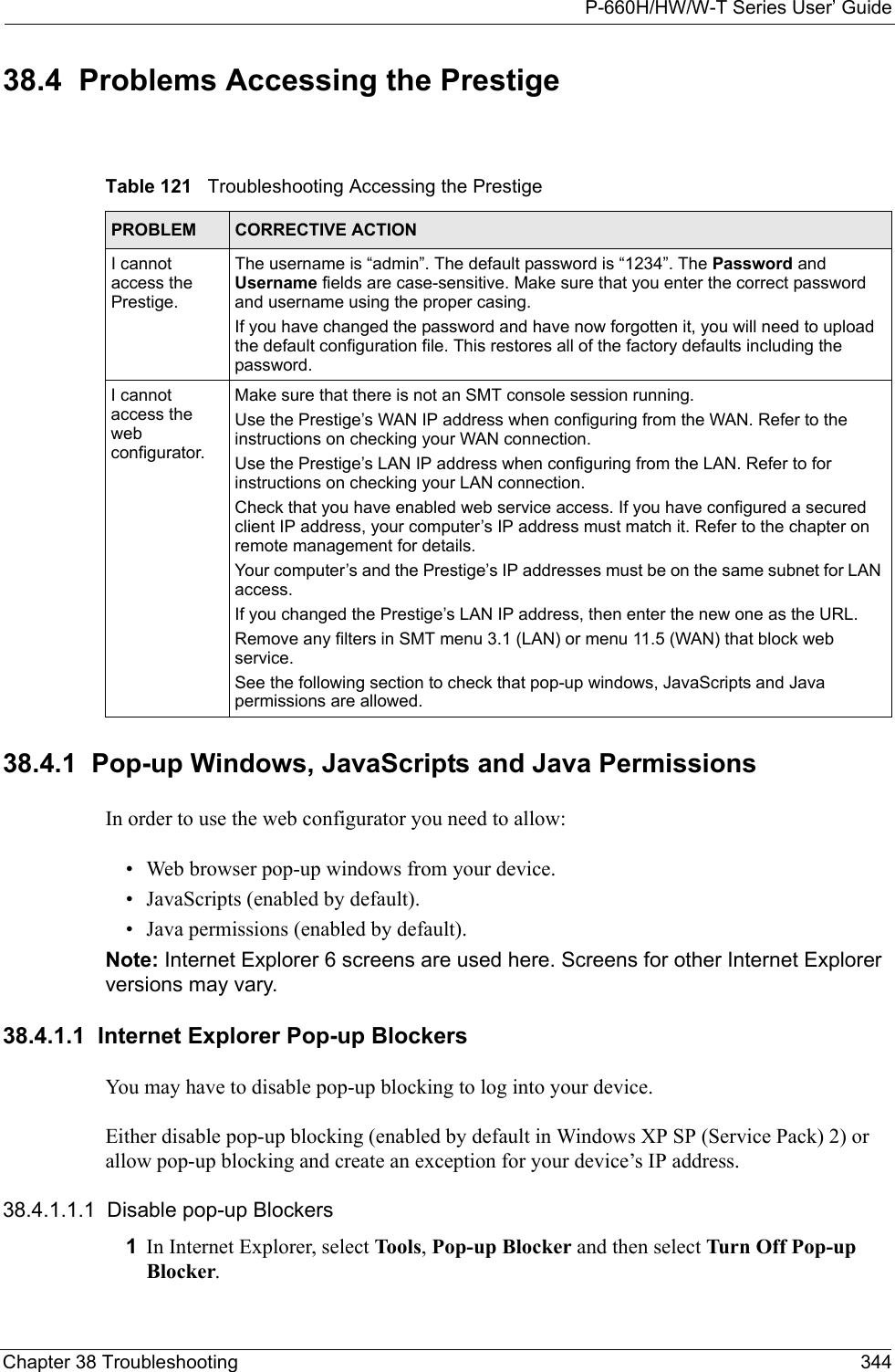
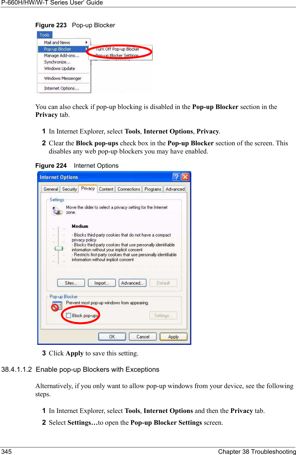
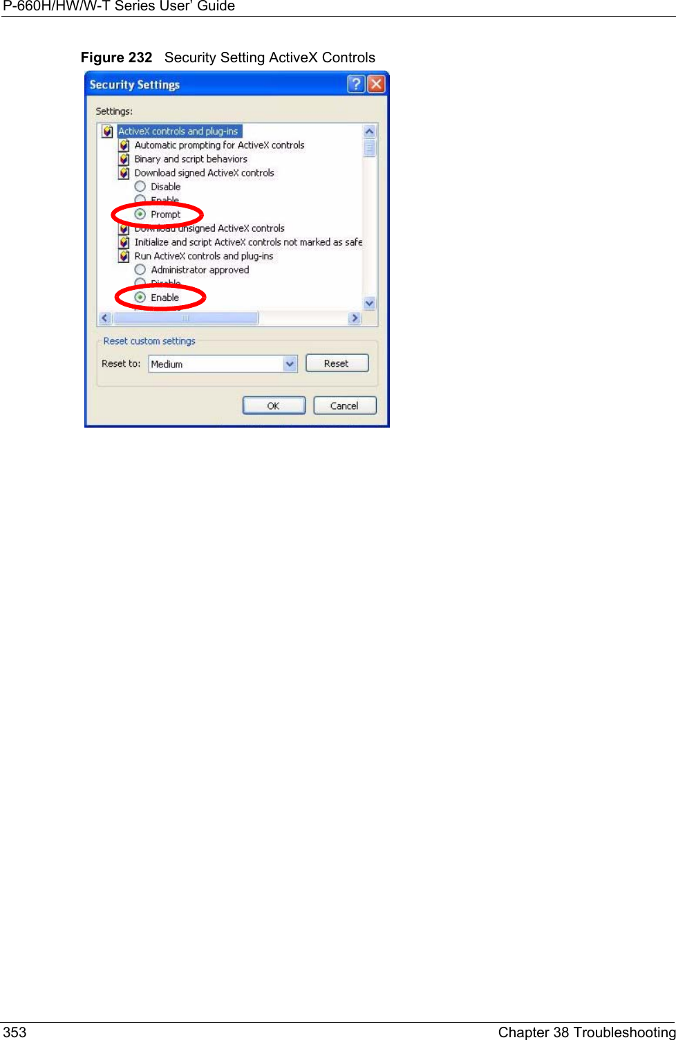
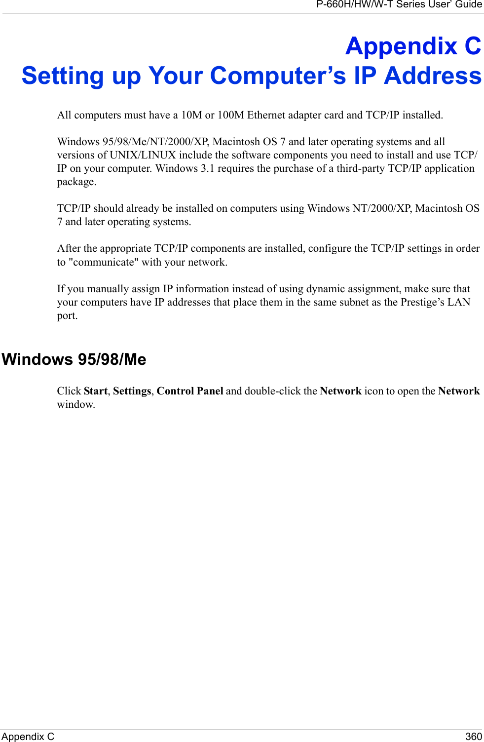
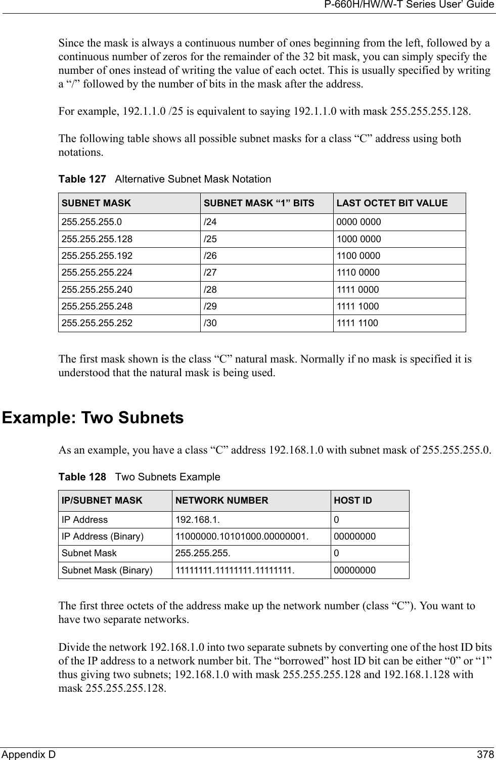
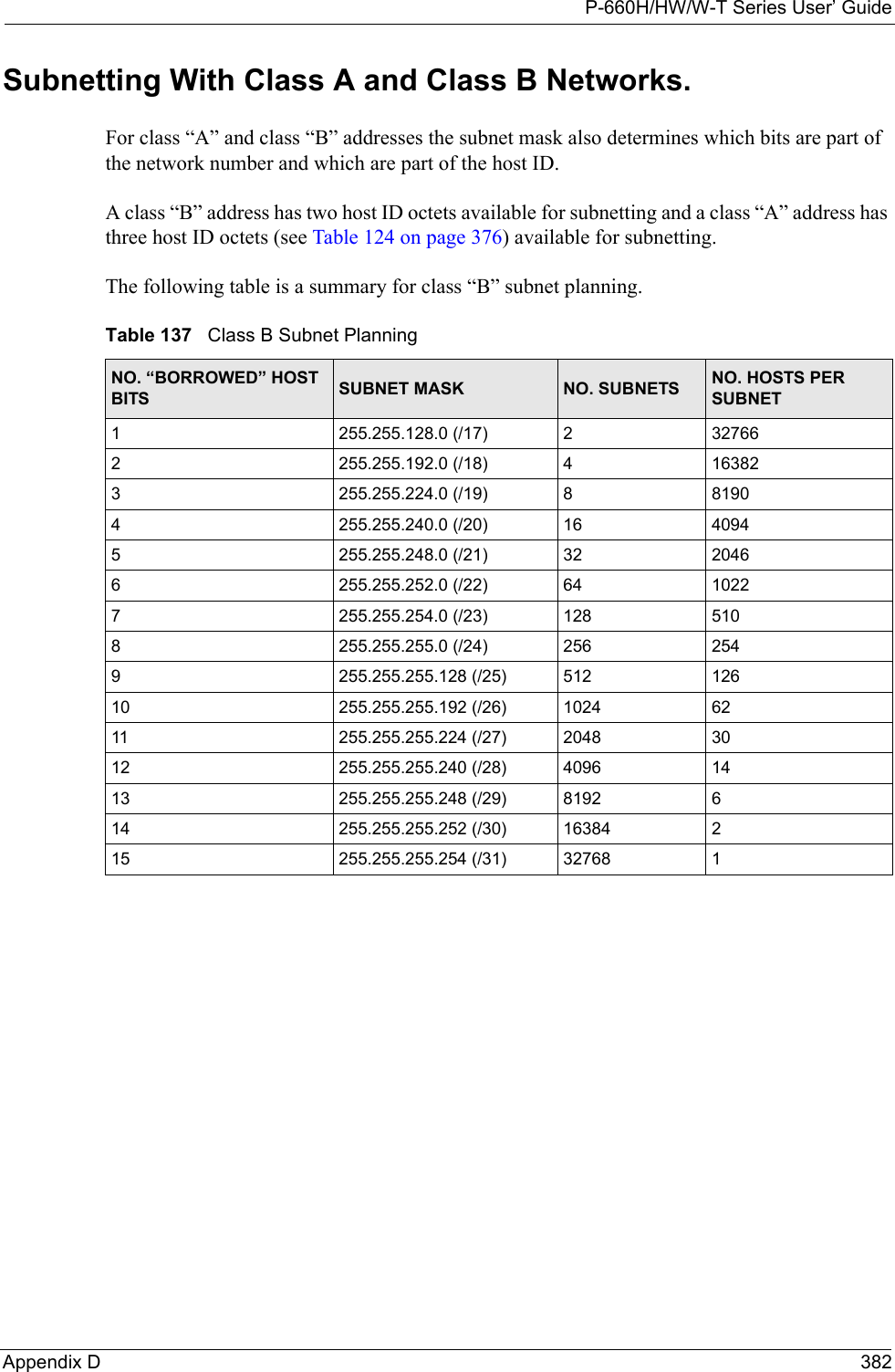
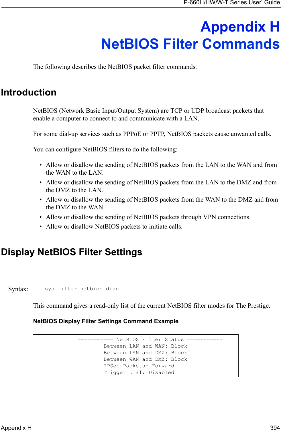
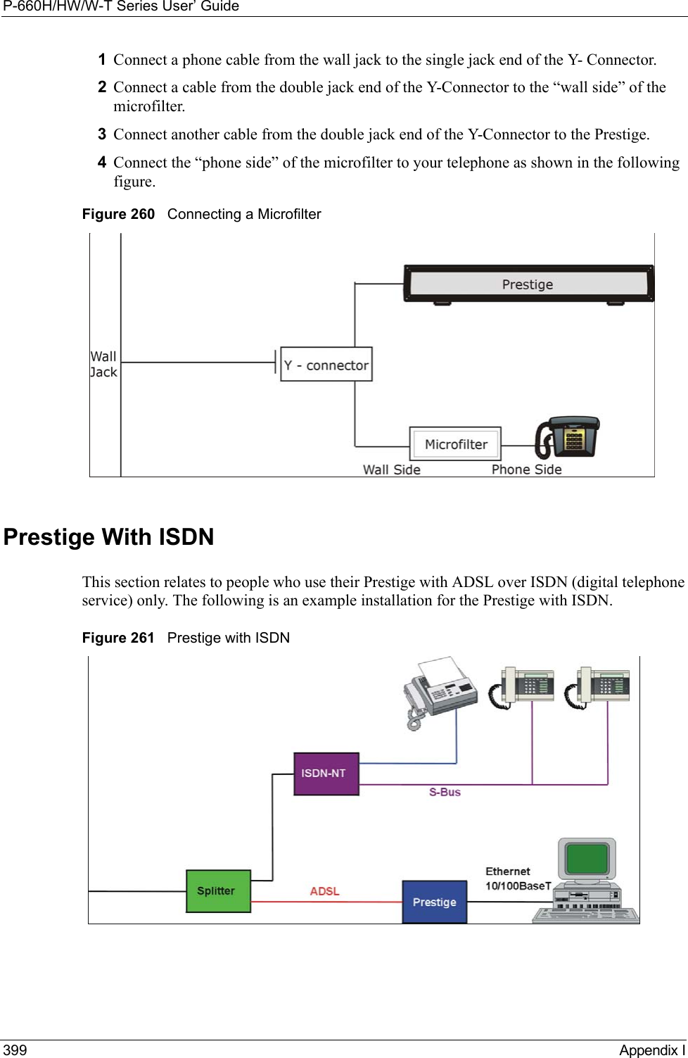
![P-660H/HW/W-T Series User’ Guide301 Chapter 32 System Information and DiagnosisFigure 193 Sample Error and Information Messages32.4.2 Syslog and AccountingThe Prestige uses the syslog facility to log the CDR (Call Detail Record) and system messages to a syslog server. Syslog and accounting can be configured in Menu 24.3.2 — System Maintenance — UNIX Syslog, as shown next.Figure 194 Menu 24.3.2 System Maintenance: Syslog and AccountingYou need to configure the UNIX syslog parameters described in the following table to activate syslog then choose what you want to log.The following are examples of the four types of syslog messages sent by the Prestige: 53 Sat Jan 01 00:00:03 2000 PP01 -WARN SNMP TRAP 0: cold start 54 Sat Jan 01 00:00:03 2000 PP01 INFO main: init completed 55 Sat Jan 01 00:00:03 2000 PP01 INFO Starting Connectivity Monitor 56 Sat Jan 01 00:00:03 2000 PP20 INFO adjtime task pause 1 day 57 Sat Jan 01 00:00:03 2000 PP21 INFO monitoring WAN connectivity 58 Sat Jan 01 00:03:06 2000 PP19 INFO SMT Password pass 59 Sat Jan 01 00:03:06 2000 PP01 INFO SMT Session Begin 60 Sat Jan 01 00:23:21 2000 PP01 INFO SMT Session End 62 Sat Jan 01 00:23:38 2000 PP19 INFO SMT Password pass 63 Sat Jan 01 00:23:38 2000 PP01 INFO SMT Session BeginClear Error Log (y/n):Menu 24.3.2 - System Maintenance - UNIX SyslogUNIX Syslog:Active= NoSyslog IP Address= ?Log Facility= Local 1Press ENTER to Confirm or ESC to Cancel:Table 107 Menu 24.3.2 System Maintenance : Syslog and AccountingPARAMETER DESCRIPTIONUNIX Syslog:Active Use [SPACE BAR] and then [ENTER] to turn syslog on or off.Syslog IP Address Type the IP address of your syslog server.Log Facility Use [SPACE BAR] and then [ENTER] to select one of seven different local options. The log facility lets you log the message in different server files. Refer to your UNIX manual.When you have completed this menu, press [ENTER] at the prompt “Press ENTER to Confirm or ESC to Cancel:” to save your configuration, or press [ESC] at any time to cancel.](https://usermanual.wiki/ZyXEL-Communications/P660HWTX.Users-Manual-4/User-Guide-566053-Page-1.png)
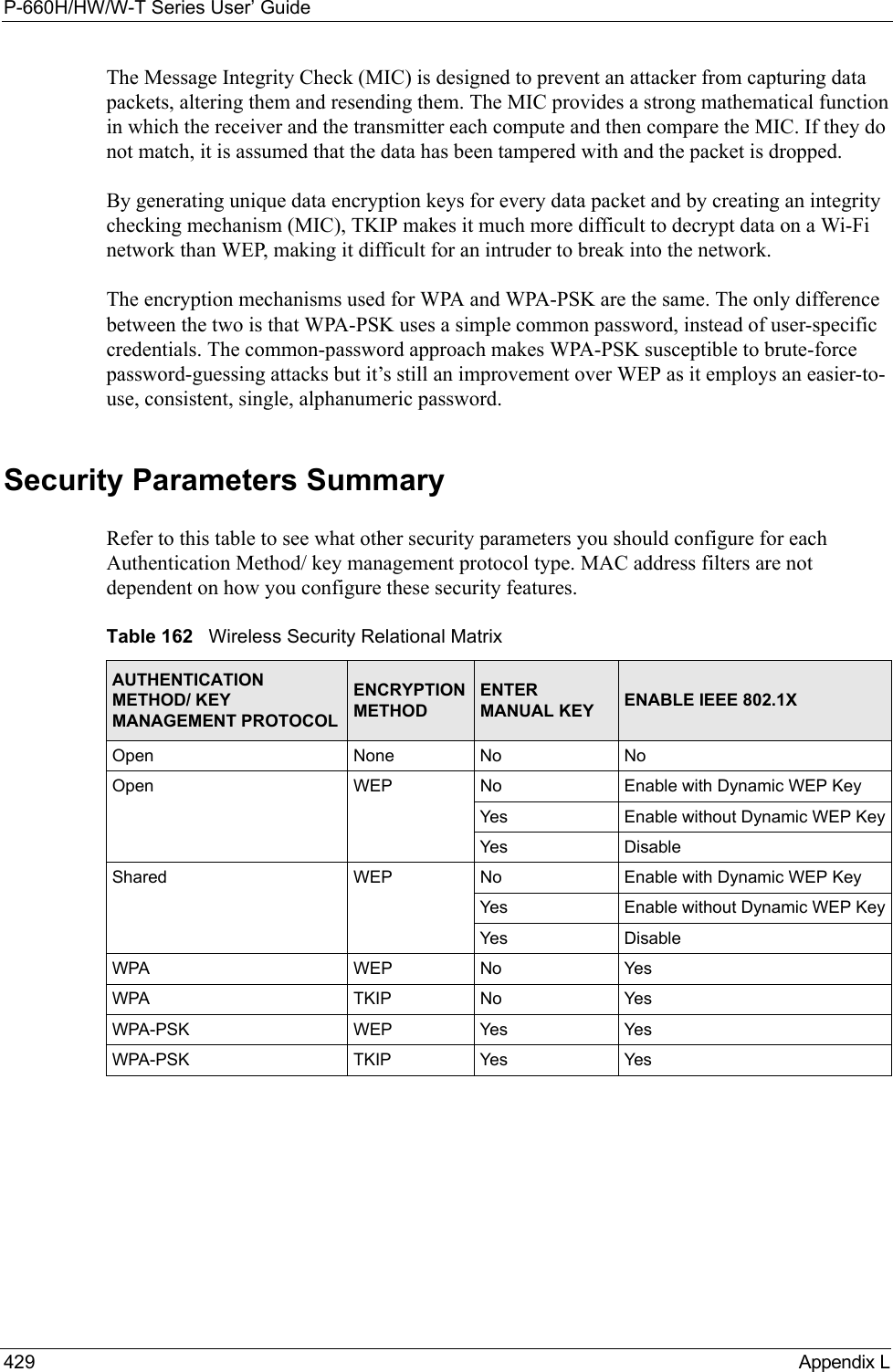
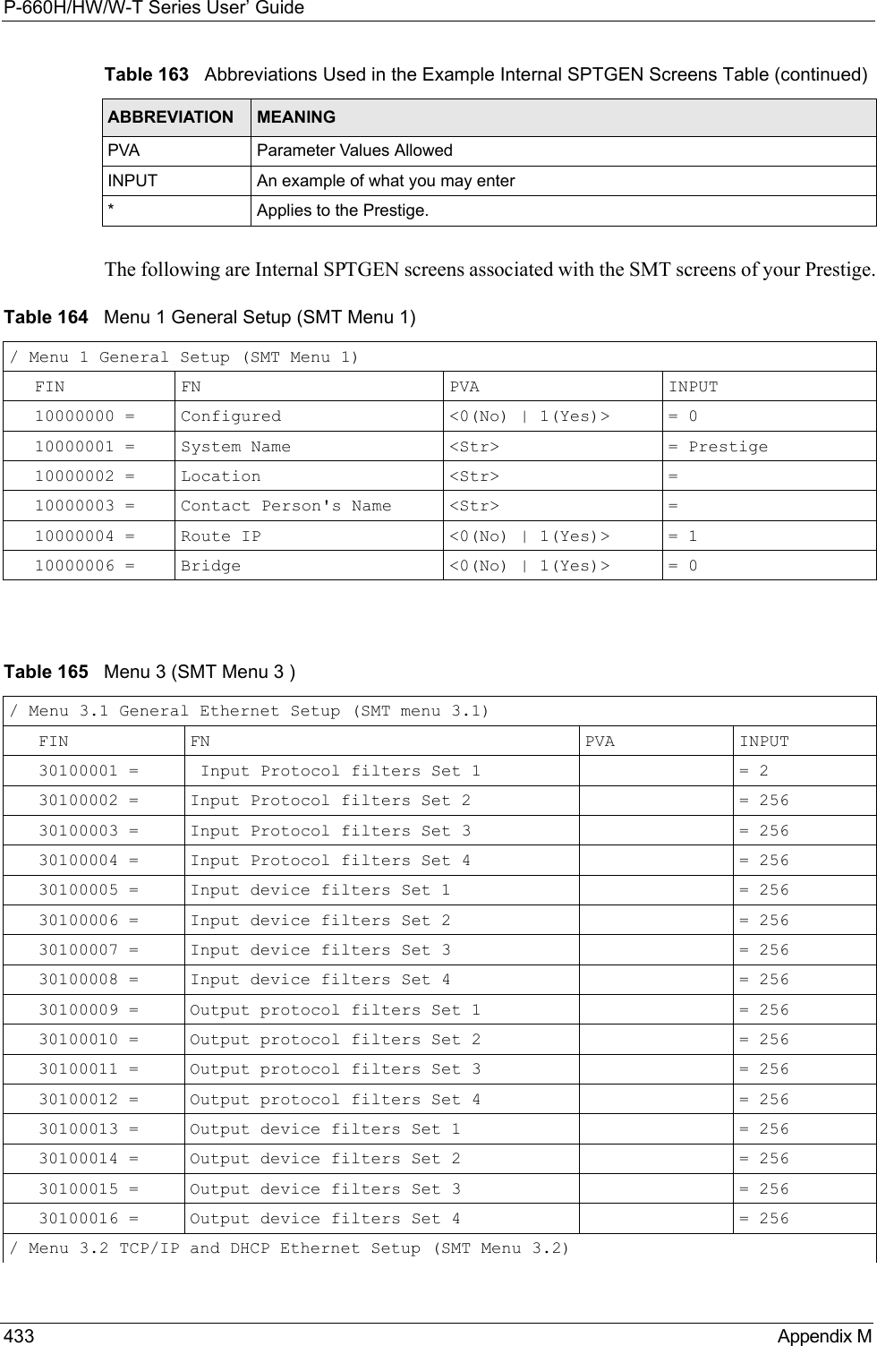
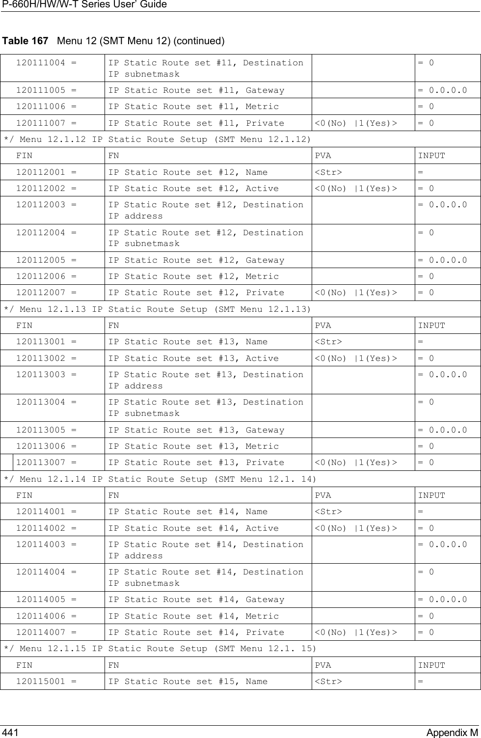
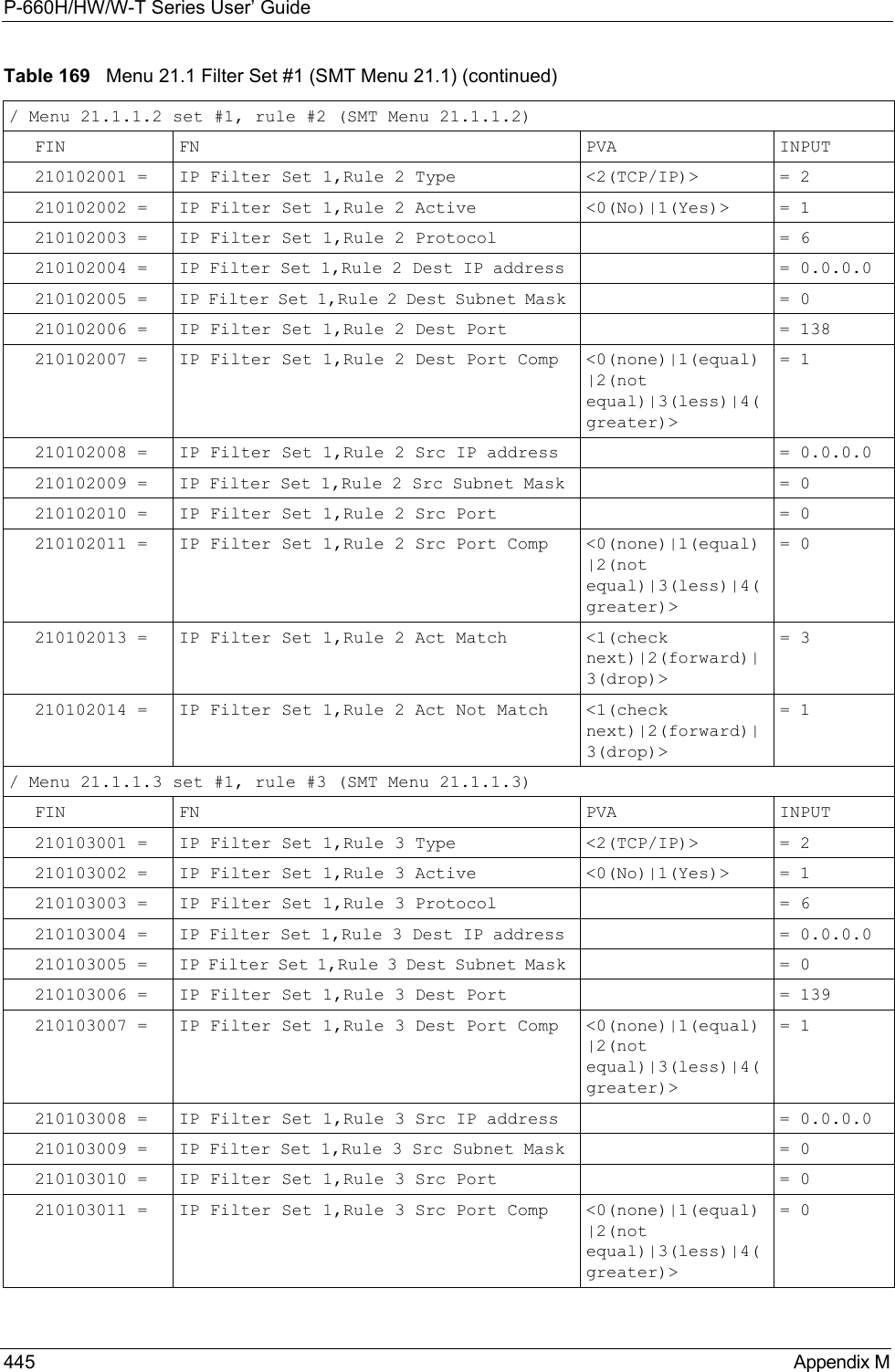
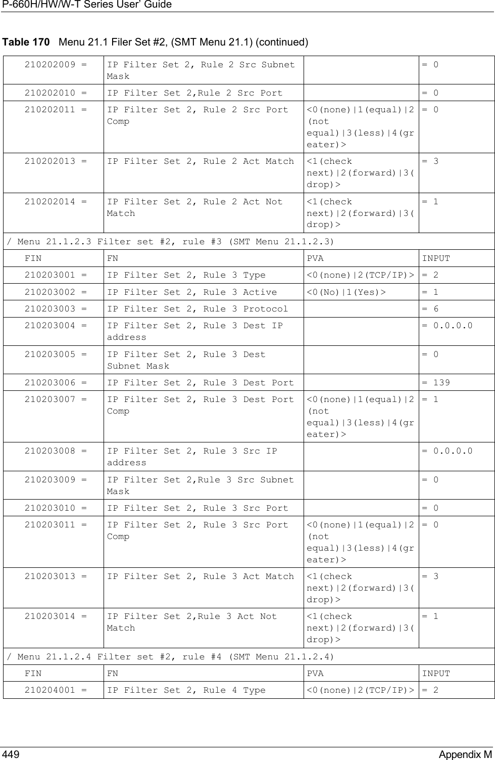
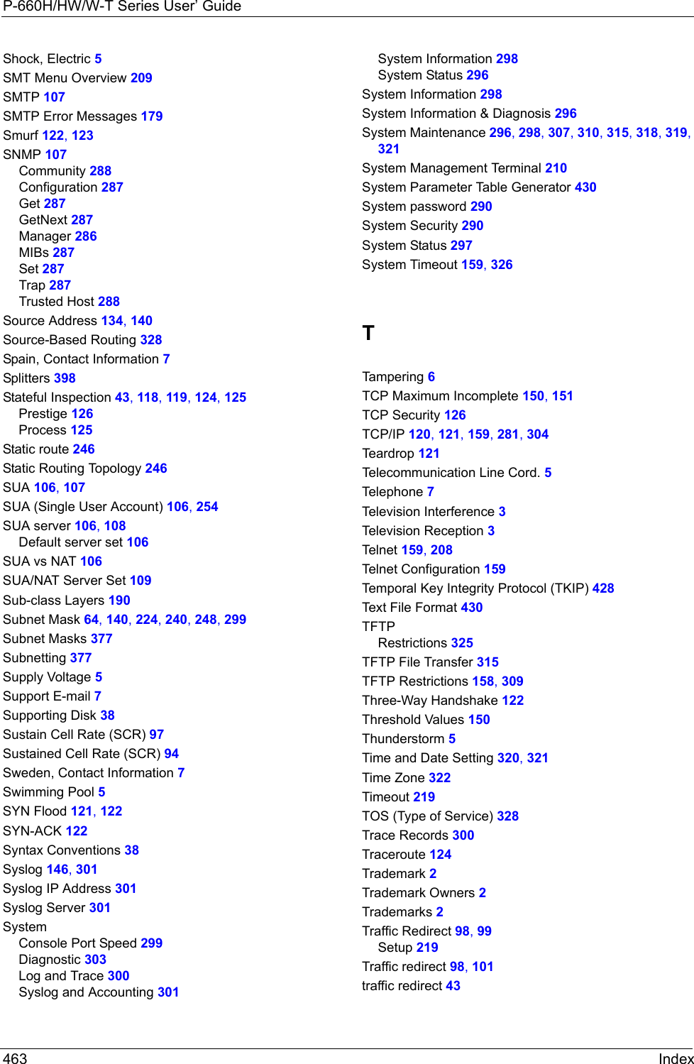
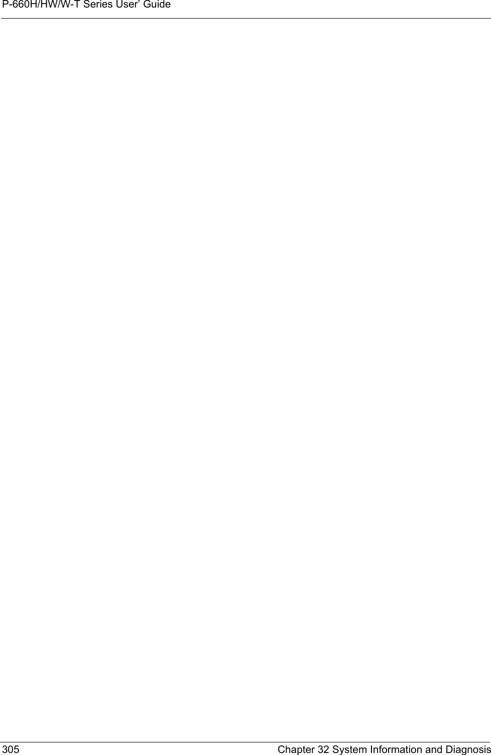
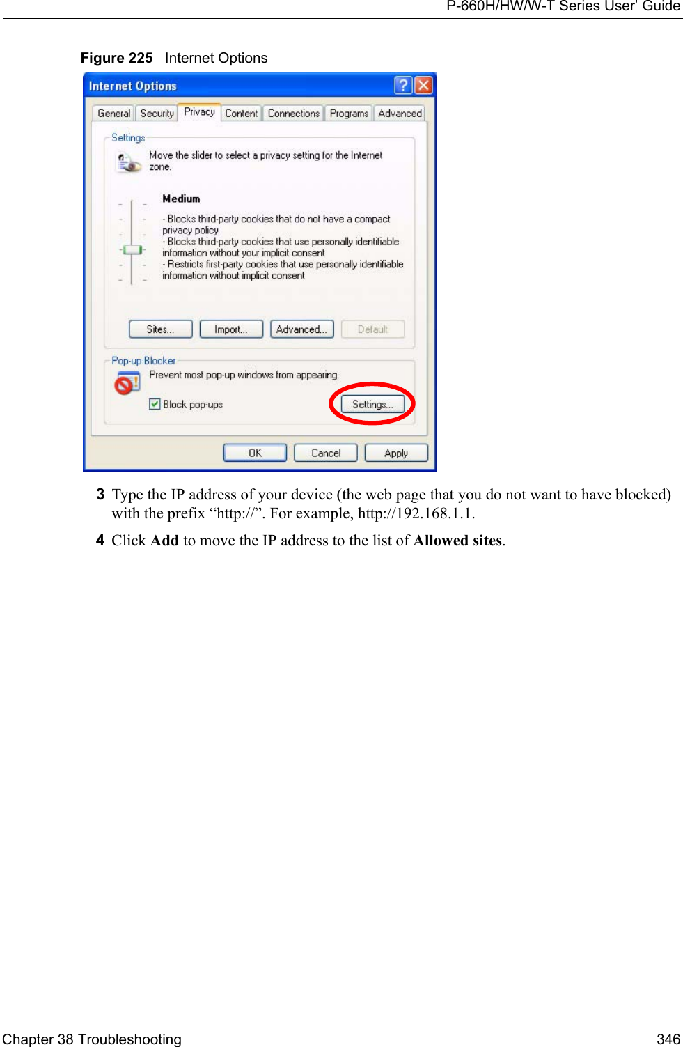
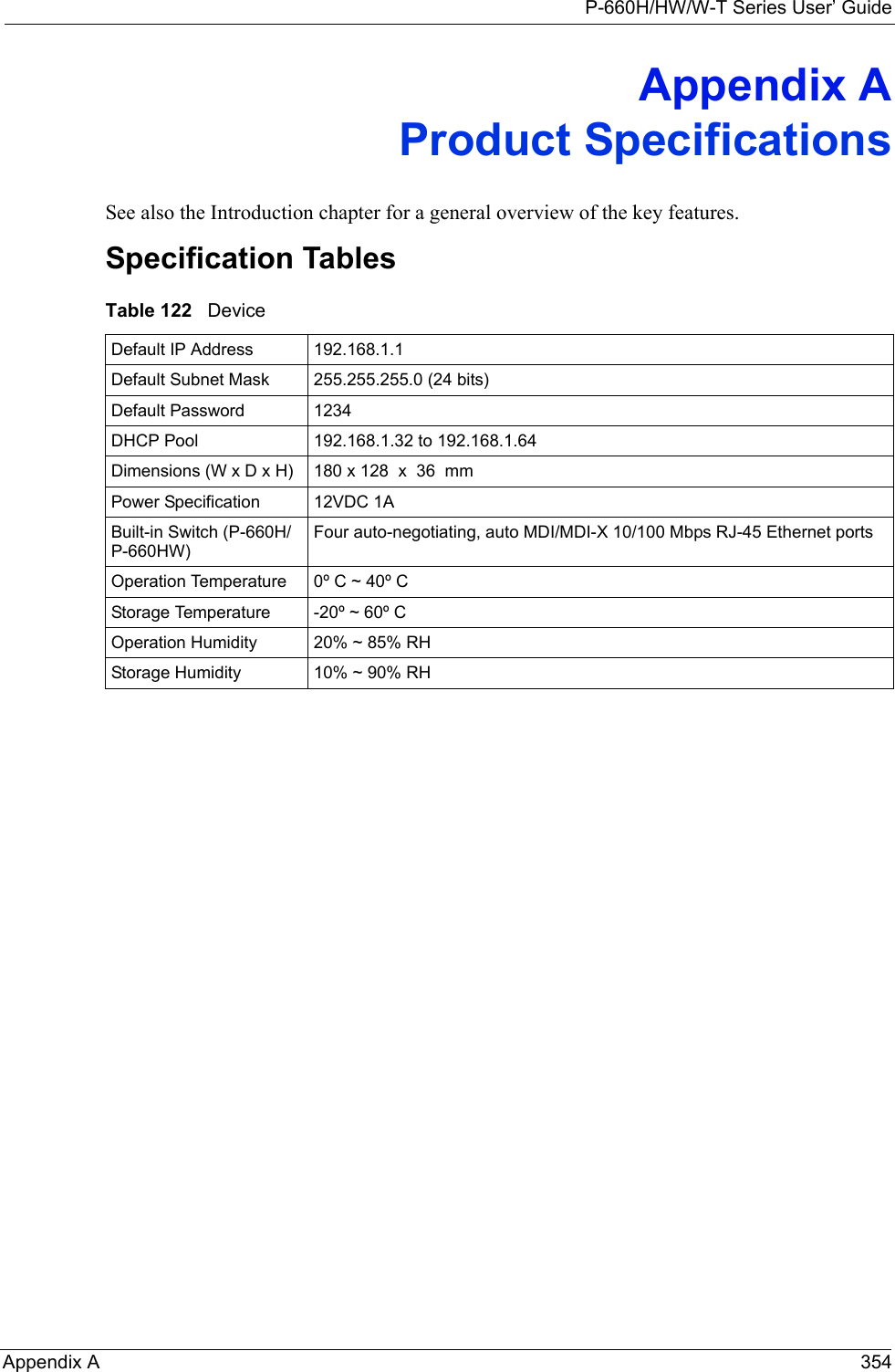
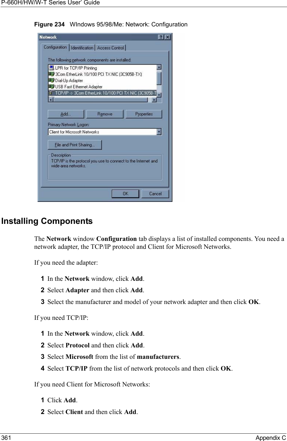
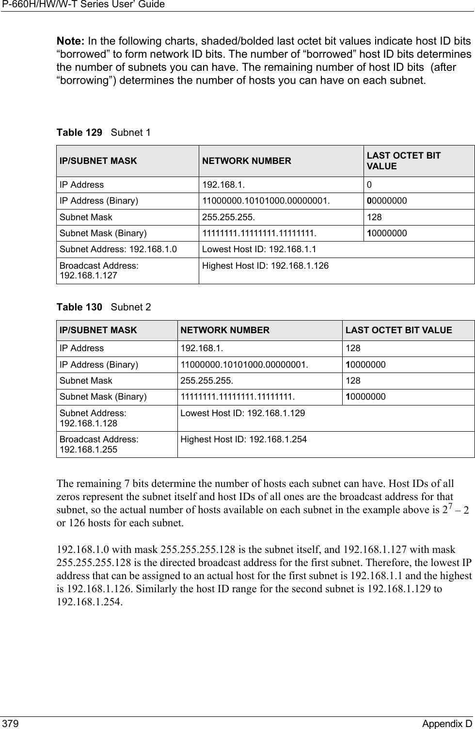
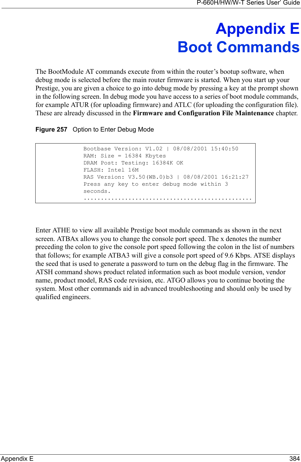
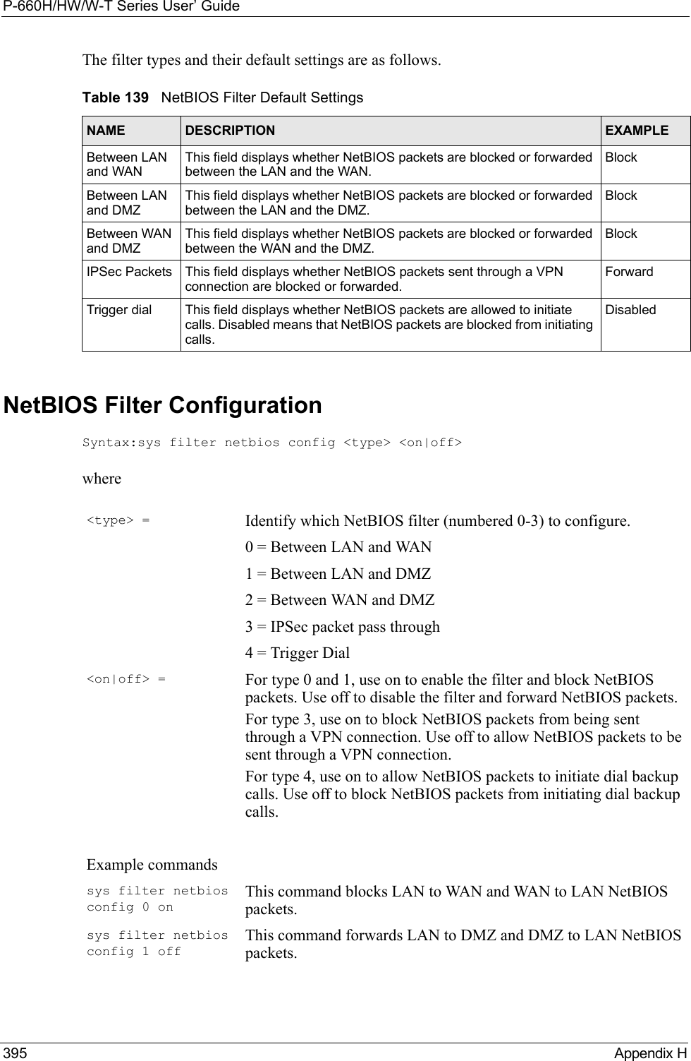
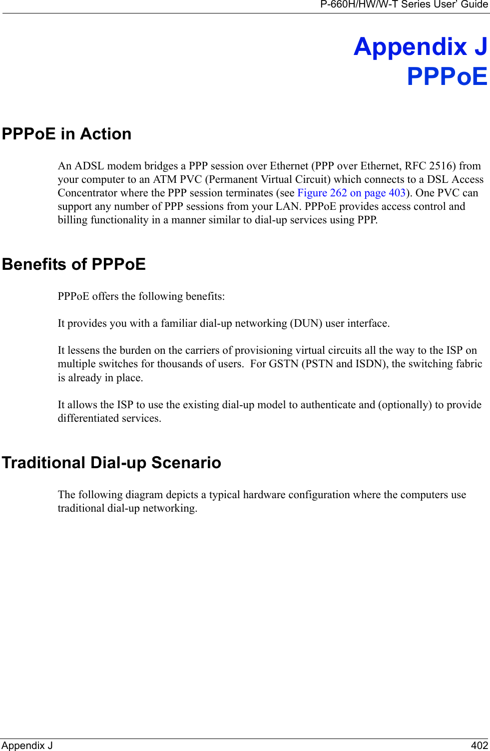
![P-660H/HW/W-T Series User’ GuideChapter 32 System Information and Diagnosis 302Figure 195 Syslog Example1 - CDRSdcmdSyslogSend ( SYSLOG_CDR, SYSLOG_INFO, String);String = board xx line xx channel xx, call xx, strboard = the hardware board IDline = the WAN ID in a boardChannel = channel ID within the WANcall = the call reference number which starts from 1 and increments by 1 for each new callstr = C01 Outgoing Call dev xx ch xx (dev:device No. ch:channel No.)C01 Incoming Call xxxxBps xxxxx (L2TP, xxxxx = Remote Call ID)C01 Incoming Call xxxx (= connected speed) xxxxx (= Remote Call ID)L02 Tunnel Connected (L2TP)C02 OutCall Connected xxxx (= connected speed) xxxxx (= Remote Call ID)C02 CLID call refusedL02 Call TerminatedC02 Call TerminatedJul 19 11:19:27 192.168.102.2 ZYXEL: board 0 line 0 channel 0, call 1, C01 Outgoing Call dev=2 ch=0 40002Jul 19 11:19:32 192.168.102.2 ZYXEL: board 0 line 0 channel 0, call 1, C02 OutCall Connected 64000 40002Jul 19 11:20:06 192.168.102.2 ZYXEL: board 0 line 0 channel 0, call 1, C02 Call Terminated2 - Packet TriggeredSdcmdSyslogSend (SYSLOG_PKTTRI, SYSLOG_NOTICE, String);String = Packet trigger: Protocol=xx Data=xxxxxxxxxx…..xProtocol: (1:IP 2:IPX 3:IPXHC 4:BPDU 5:ATALK 6:IPNG)Data: We will send forty-eight Hex characters to the serverJul 19 11:28:39 192.168.102.2 ZYXEL: Packet Trigger: Protocol=1, Data=4500003c100100001f010004c0a86614ca849a7b08004a5c020001006162636465666768696a6b6c6d6e6f7071727374Jul 19 11:28:56 192.168.102.2 ZYXEL: Packet Trigger: Protocol=1, Data=4500002c1b0140001f06b50ec0a86614ca849a7b0427001700195b3e00000000600220008cd40000020405b4Jul 19 11:29:06 192.168.102.2 ZYXEL: Packet Trigger: Protocol=1, Data=45000028240140001f06ac12c0a86614ca849a7b0427001700195b451d14301350040000776000003 - Filter LogSdcmdSyslogSend (SYSLOG_FILLOG, SYSLOG_NOTICE, String);String = IP[Src=xx.xx.xx.xx Dst=xx.xx.xx.xx prot spo=xxxx dpo=xxxx] S04>R01mDIP[…] is the packet header and S04>R01mD means filter set 4 (S) and rule 1 (R), match (m), drop (D).Src: Source AddressDst: Destination Address](https://usermanual.wiki/ZyXEL-Communications/P660HWTX.Users-Manual-4/User-Guide-566053-Page-2.png)
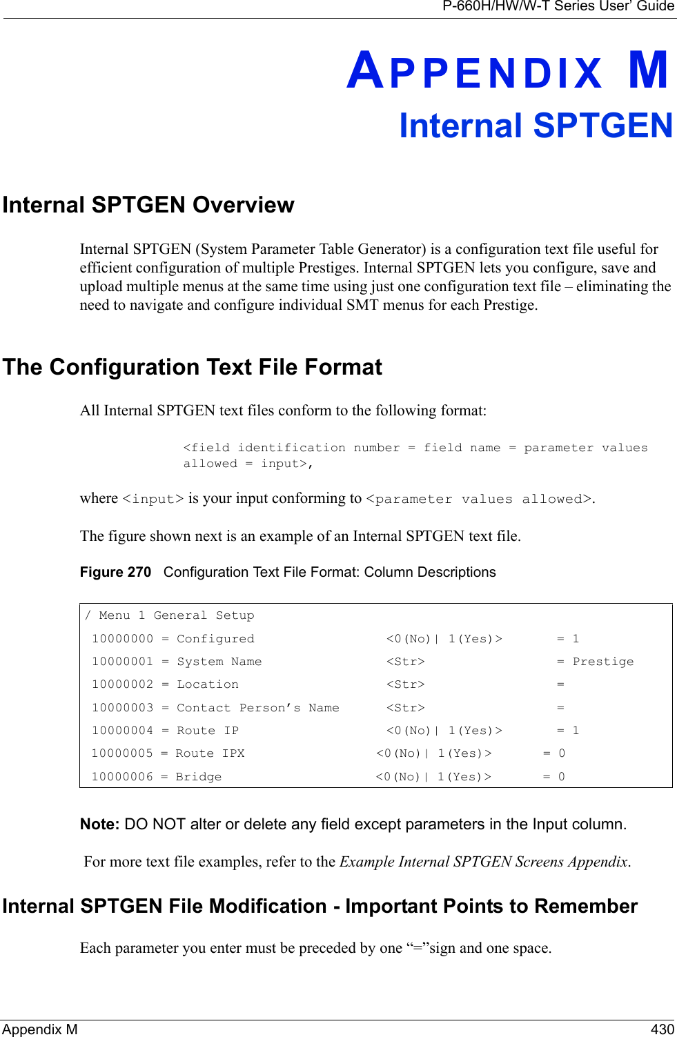
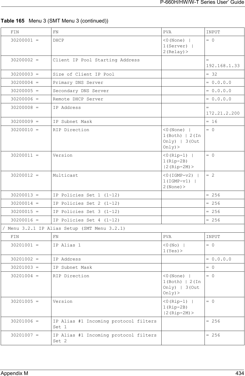
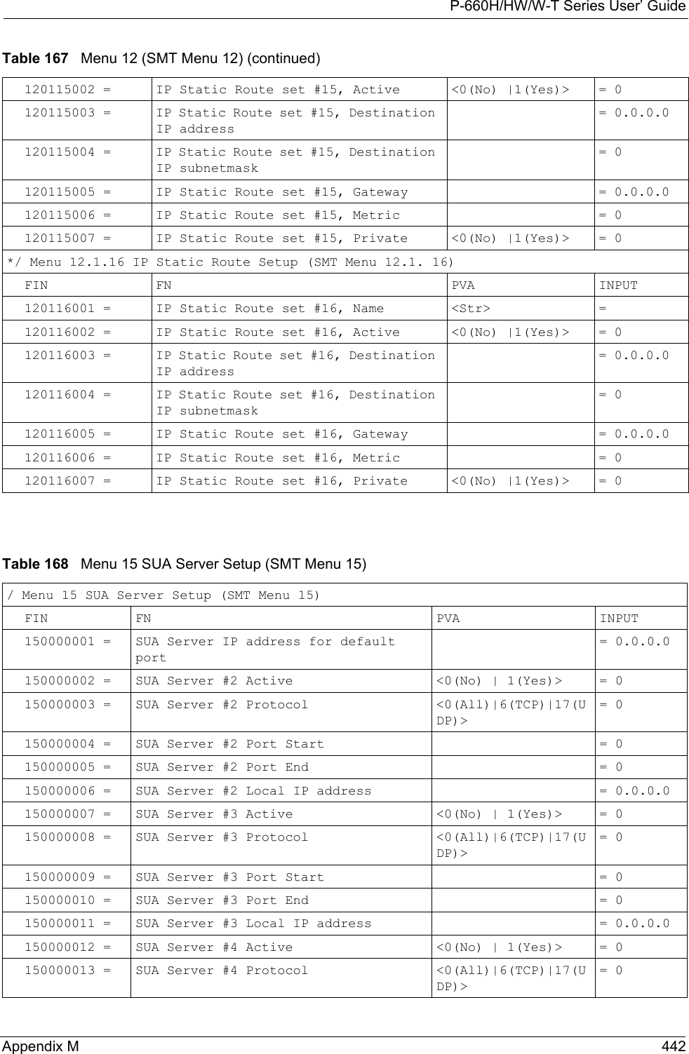
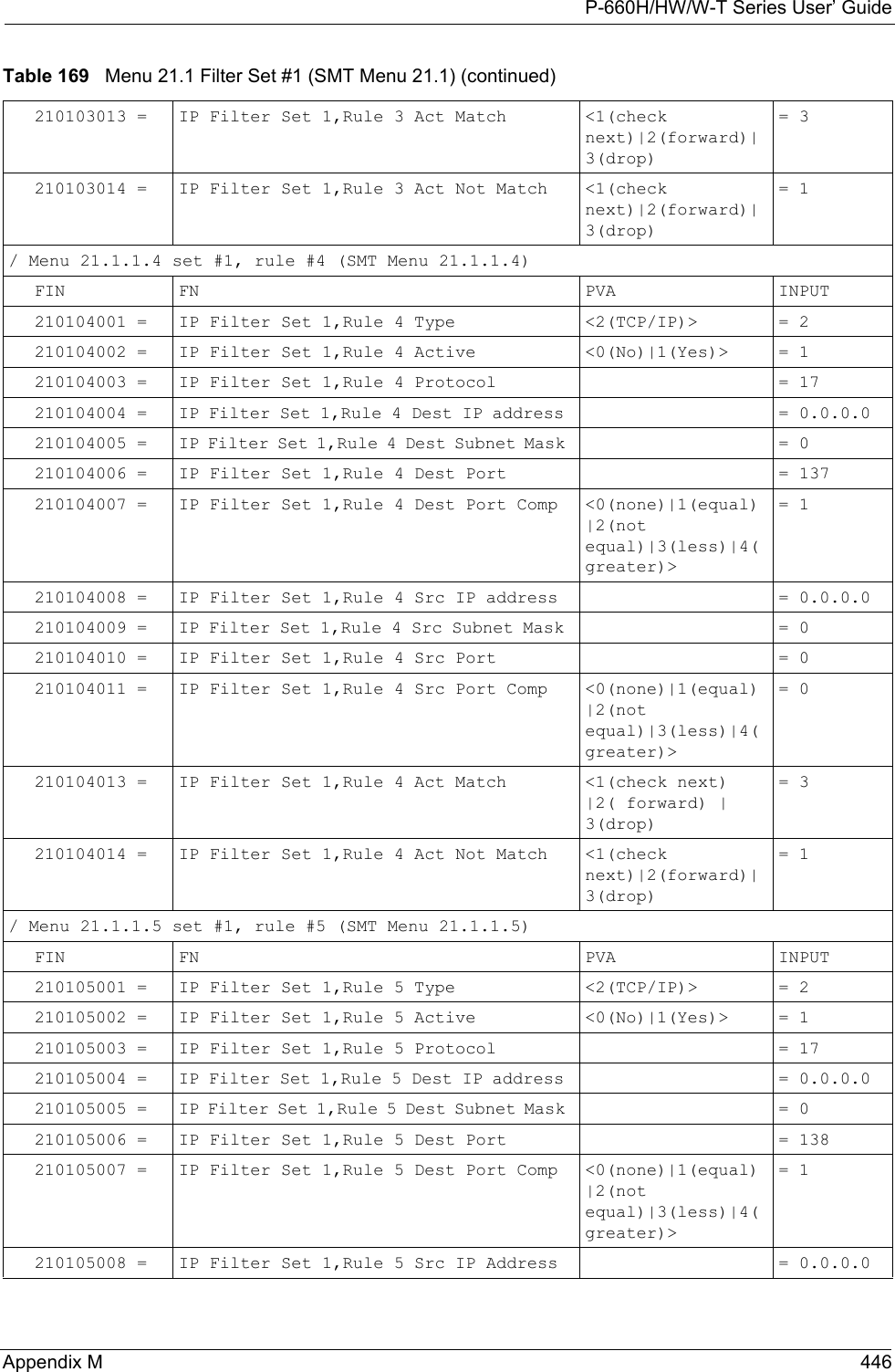
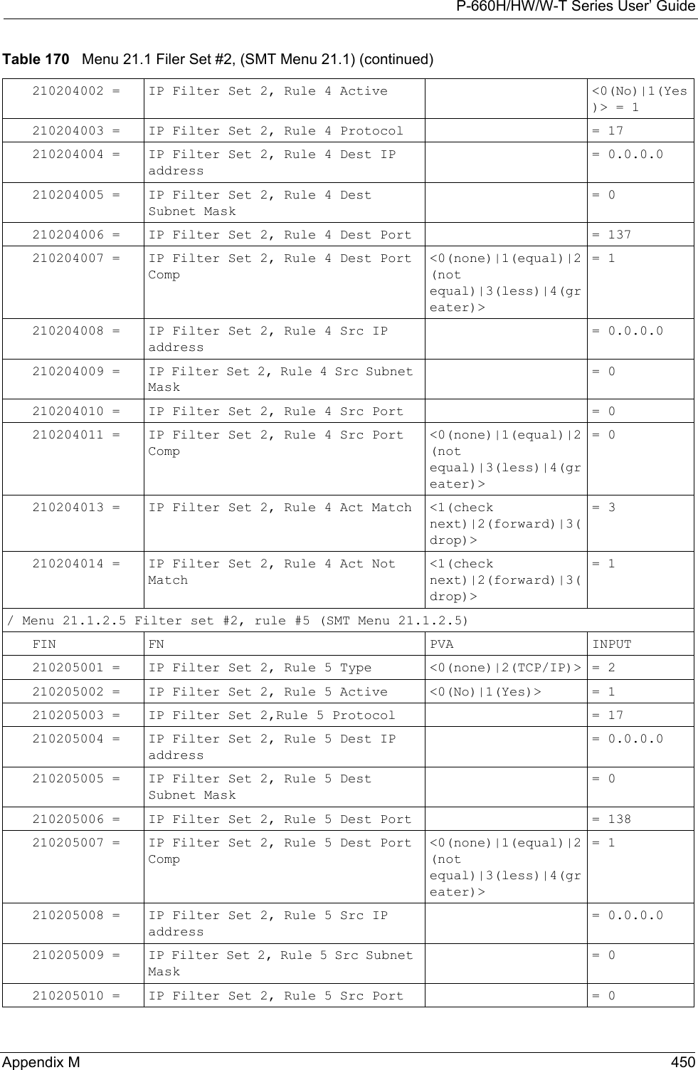
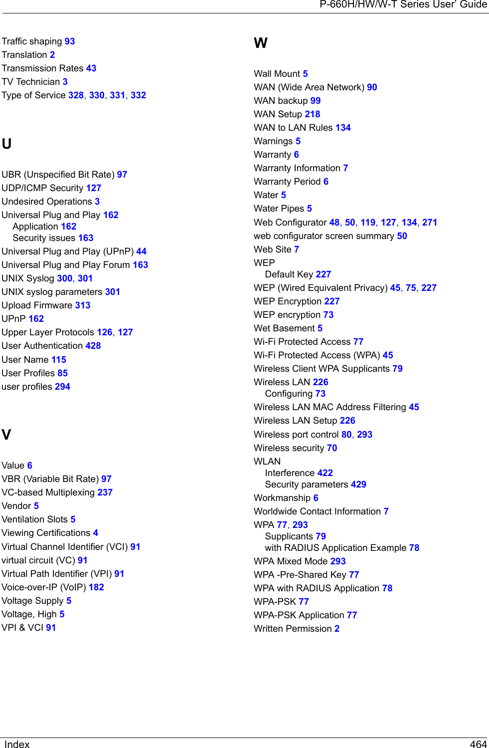
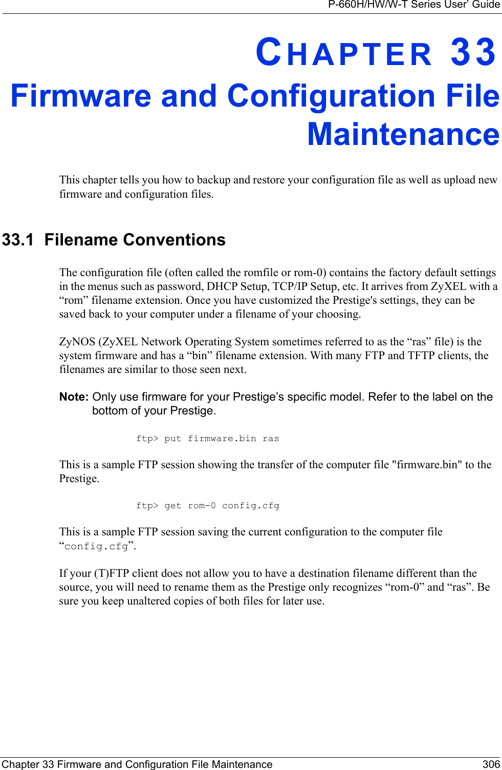
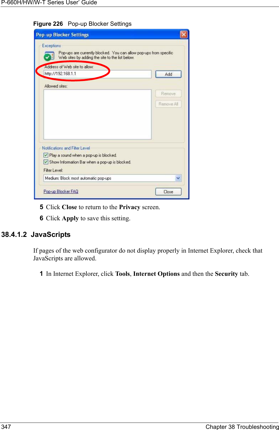
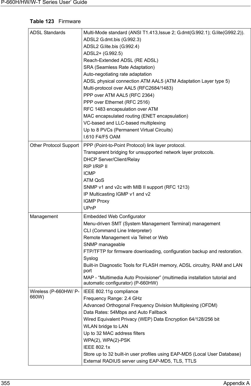
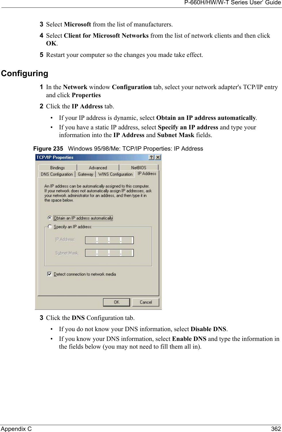
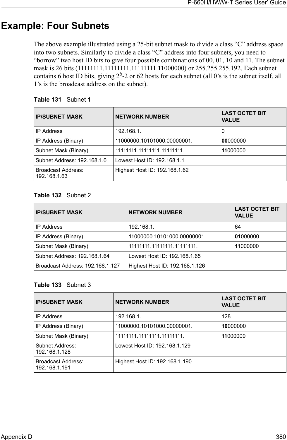
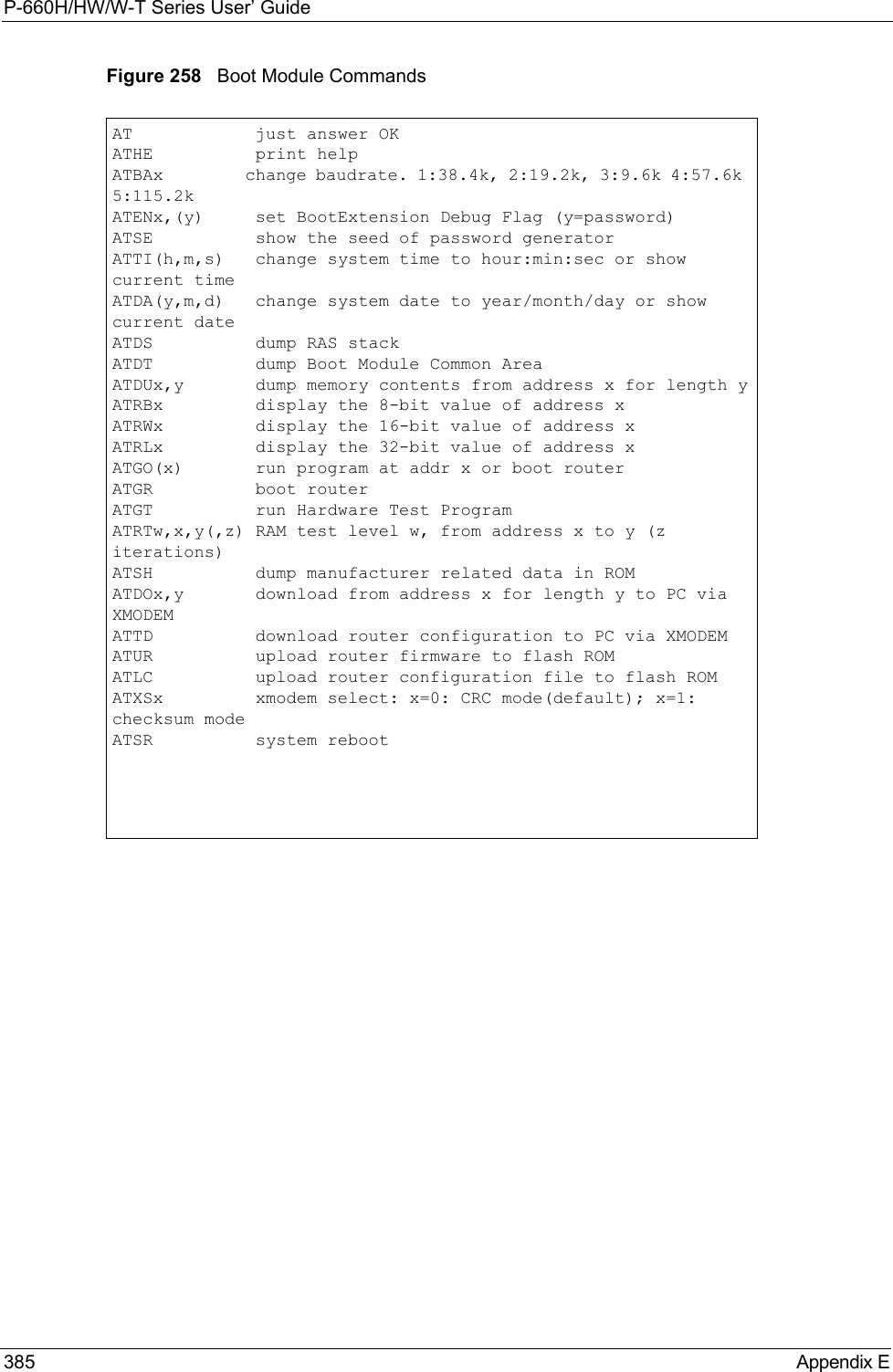
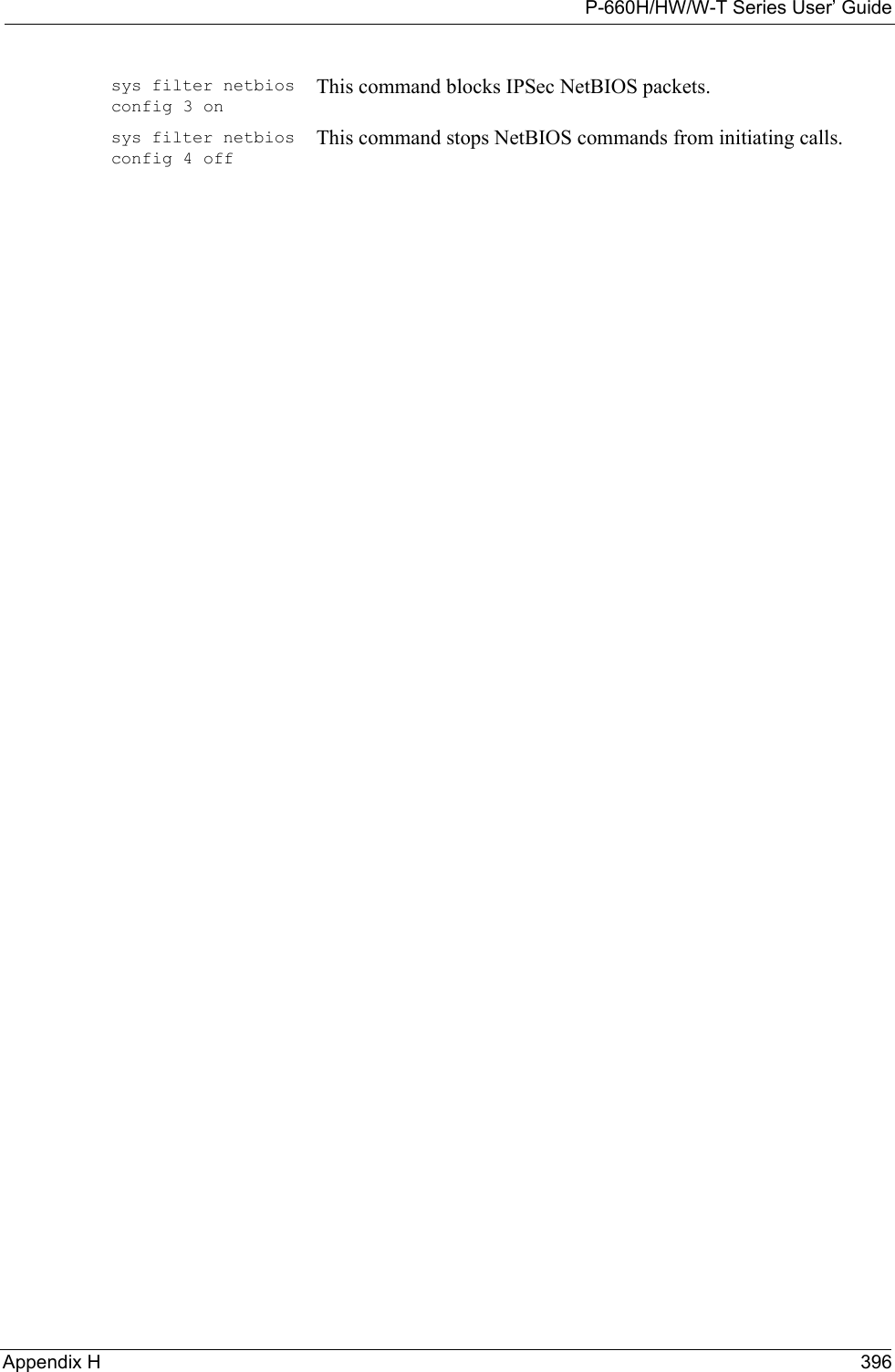
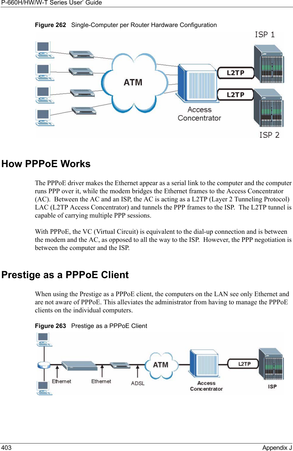
![P-660H/HW/W-T Series User’ Guide303 Chapter 32 System Information and Diagnosis32.5 DiagnosticThe diagnostic facility allows you to test the different aspects of your Prestige to determine if it is working properly. Menu 24.4 allows you to choose among various types of diagnostic tests to evaluate your system, as shown in the following figure.Follow the procedure next to get to Diagnostic:1From the main menu, type 24 to open Menu 24 – System Maintenance.2From this menu, type 4. Diagnostic to open Menu 24.4 – System Maintenance – Diagnostic.Figure 196 Menu 24.4 System Maintenance : Diagnosticprot: Protocol (“TCP”, ”UDP”, ”ICMP”)spo: Source portdpo: Destination portJul 19 14:43:55 192.168.102.2 ZYXEL: IP [Src=202.132.154.123 Dst=255.255.255.255 UDP spo=0208 dpo=0208]} S03>R01mFJul 19 14:44:00 192.168.102.2 ZYXEL: IP [Src=192.168.102.20 Dst=202.132.154.1 UDP spo=05d4 dpo=0035]} S03>R01mFJul 19 14:44:04 192.168.102.2 ZYXEL: IP [Src=192.168.102.20 Dst=202.132.154.1 UDP spo=05d4 dpo=0035]} S03>R01mF4 - PPP LogSdcmdSyslogSend (SYSLOG_PPPLOG, SYSLOG_NOTICE, String);String = ppp:Proto Starting / ppp:Proto Opening / ppp:Proto Closing / ppp:Proto ShutdownProto = LCP / ATCP / BACP / BCP / CBCP / CCP / CHAP/ PAP / IPCP / IPXCPJul 19 11:42:44 192.168.102.2 ZYXEL: ppp:LCP ClosingJul 19 11:42:49 192.168.102.2 ZYXEL: ppp:IPCP ClosingJul 19 11:42:54 192.168.102.2 ZYXEL: ppp:CCP ClosingFigure 195 Syslog Example (continued)Menu 24.4 - System Maintenance - Diagnostic xDSL System 1. Reset xDSL 21. Reboot System 22. Command Mode TCP/IP 12. Ping Host Enter Menu Selection Number: Host IP Address= N/A](https://usermanual.wiki/ZyXEL-Communications/P660HWTX.Users-Manual-4/User-Guide-566053-Page-3.png)
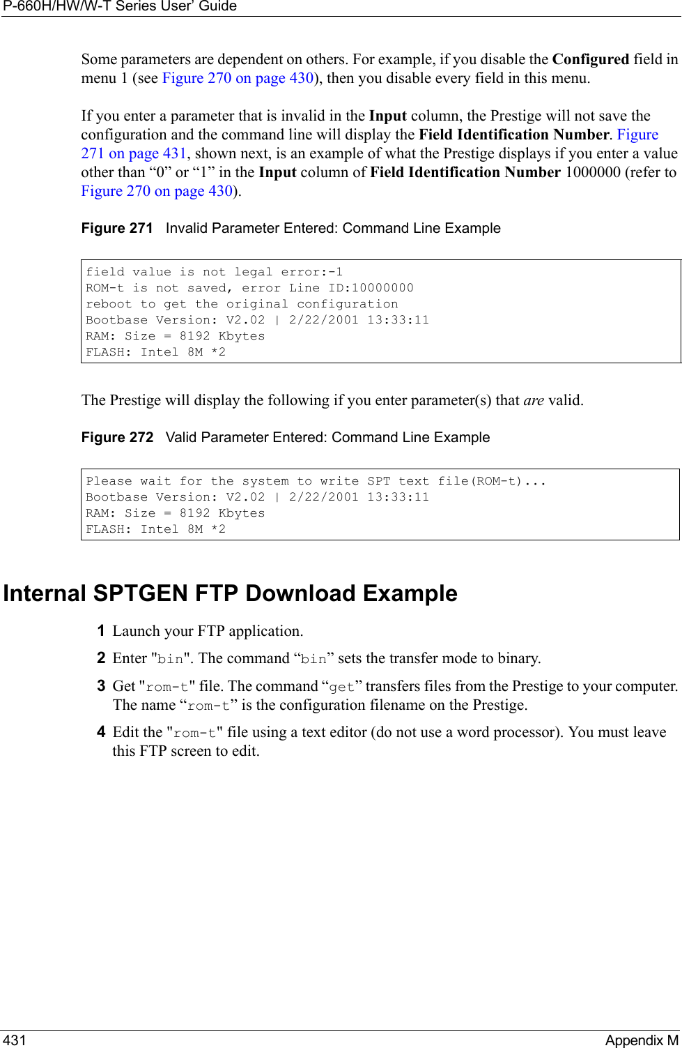
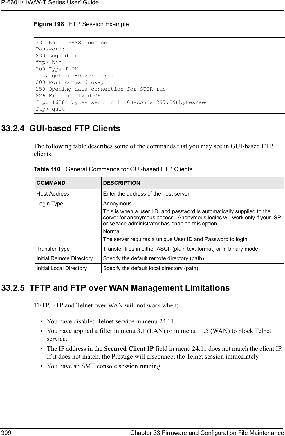
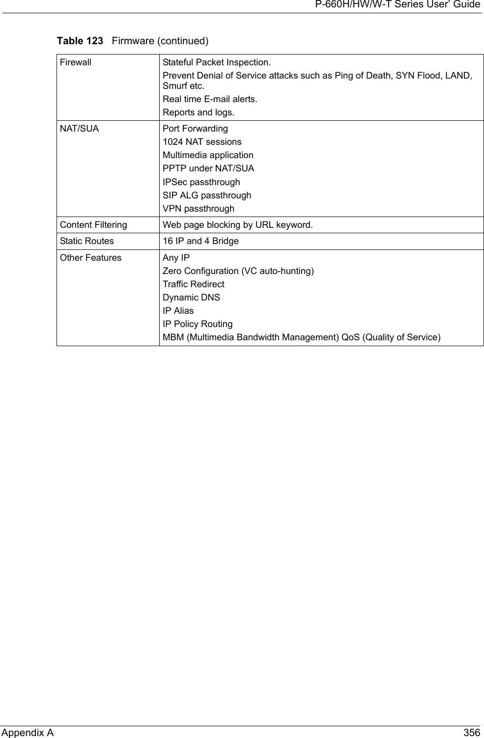
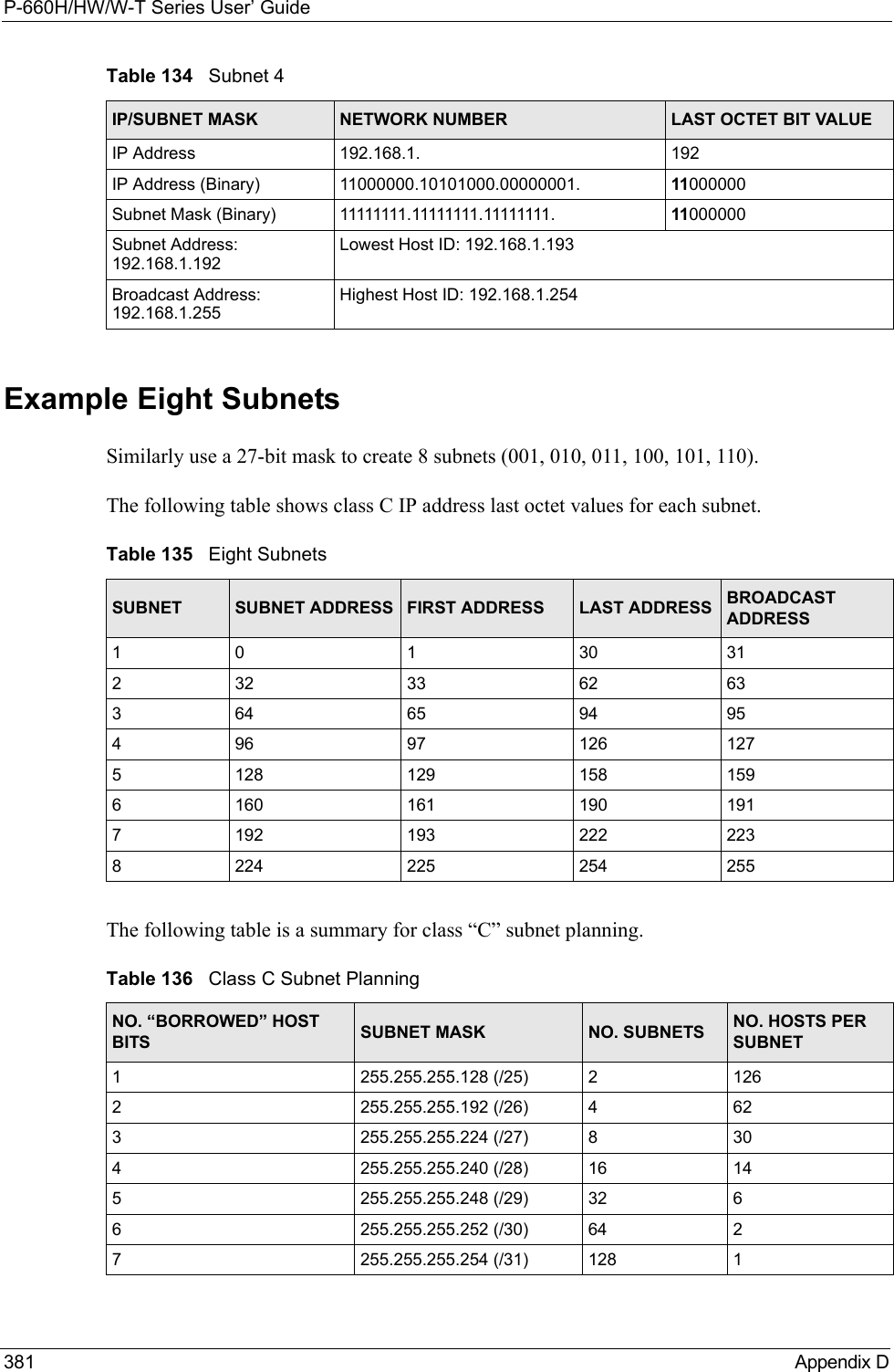
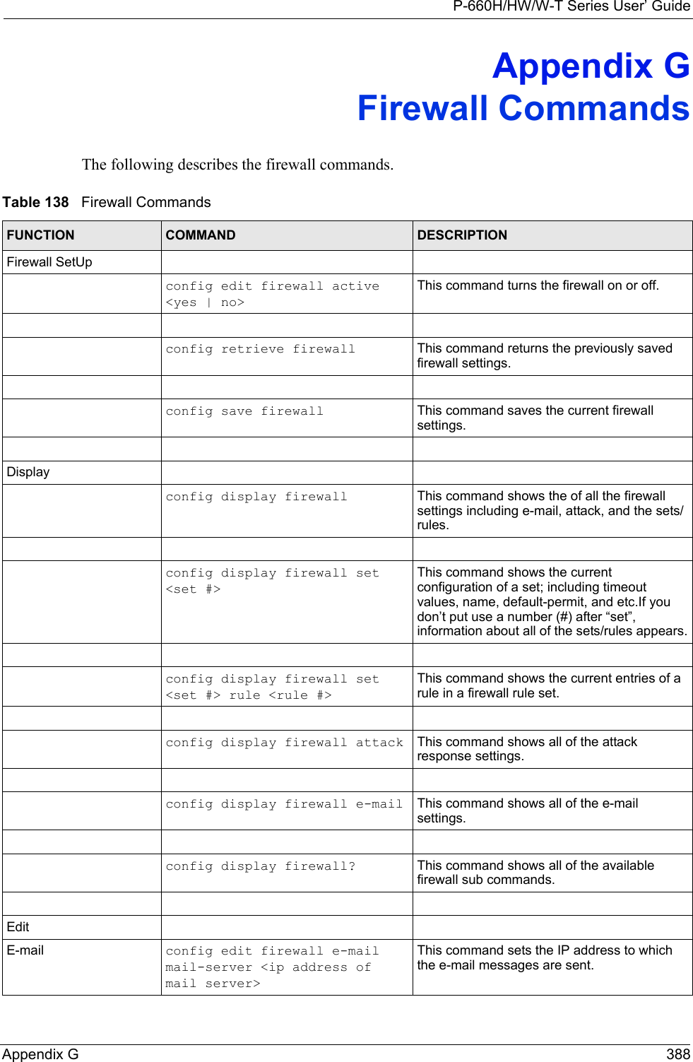
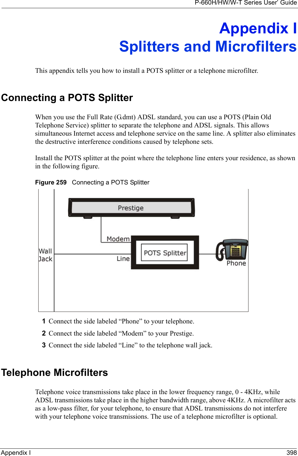
![P-660H/HW/W-T Series User’ GuideChapter 33 Firmware and Configuration File Maintenance 308Figure 197 Telnet in Menu 24.533.2.2 Using the FTP Command from the Command Line1Launch the FTP client on your computer.2Enter “open”, followed by a space and the IP address of your Prestige. 3Press [ENTER] when prompted for a username.4Enter your password as requested (the default is “1234”).5Enter “bin” to set transfer mode to binary.6Use “get” to transfer files from the Prestige to the computer, for example, “get rom-0 config.rom” transfers the configuration file on the Prestige to your computer and renames it “config.rom”. See earlier in this chapter for more information on filename conventions.7Enter “quit” to exit the ftp prompt. 33.2.3 Example of FTP Commands from the Command Line Menu 24.5 - System Maintenance - Backup ConfigurationTo transfer the configuration file to your workstation, follow the procedure below:1. Launch the FTP client on your workstation.2. Type "open" and the IP address of your Prestige. Then type "root" and SMT password as requested.3. Locate the 'rom-0' file.4. Type 'get rom-0' to back up the current Prestige configuration to your workstation.For details on FTP commands, please consult the documentation of your FTP client program. For details on backup using TFTP (note that you must remain in this menu to back up using TFTP), please see your Prestige manual.Press ENTER to Exit:](https://usermanual.wiki/ZyXEL-Communications/P660HWTX.Users-Manual-4/User-Guide-566053-Page-8.png)
![P-660H/HW/W-T Series User’ GuideChapter 33 Firmware and Configuration File Maintenance 31033.2.6 Backup Configuration Using TFTPThe Prestige supports the up/downloading of the firmware and the configuration file using TFTP (Trivial File Transfer Protocol) over LAN. Although TFTP should work over WAN as well, it is not recommended.To use TFTP, your computer must have both telnet and TFTP clients. To backup the configuration file, follow the procedure shown next.1Use telnet from your computer to connect to the Prestige and log in. Because TFTP does not have any security checks, the Prestige records the IP address of the telnet client and accepts TFTP requests only from this address.2Put the SMT in command interpreter (CI) mode by entering 8 in Menu 24 – System Maintenance.3Enter command “sys stdio 0” to disable the SMT timeout, so the TFTP transfer will not be interrupted. Enter command “sys stdio 5” to restore the five-minute SMT timeout (default) when the file transfer is complete.4Launch the TFTP client on your computer and connect to the Prestige. Set the transfer mode to binary before starting data transfer.5Use the TFTP client (see the example below) to transfer files between the Prestige and the computer. The file name for the configuration file is “rom-0” (rom-zero, not capital o).Note that the telnet connection must be active and the SMT in CI mode before and during the TFTP transfer. For details on TFTP commands (see following example), please consult the documentation of your TFTP client program. For UNIX, use “get” to transfer from the Prestige to the computer and “binary” to set binary transfer mode.33.2.7 TFTP Command ExampleThe following is an example TFTP command:tftp [-i] host get rom-0 config.romwhere “i” specifies binary image transfer mode (use this mode when transferring binary files), “host” is the Prestige IP address, “get” transfers the file source on the Prestige (rom-0, name of the configuration file on the Prestige) to the file destination on the computer and renames it config.rom.33.2.8 GUI-based TFTP ClientsThe following table describes some of the fields that you may see in GUI-based TFTP clients.](https://usermanual.wiki/ZyXEL-Communications/P660HWTX.Users-Manual-4/User-Guide-566053-Page-10.png)
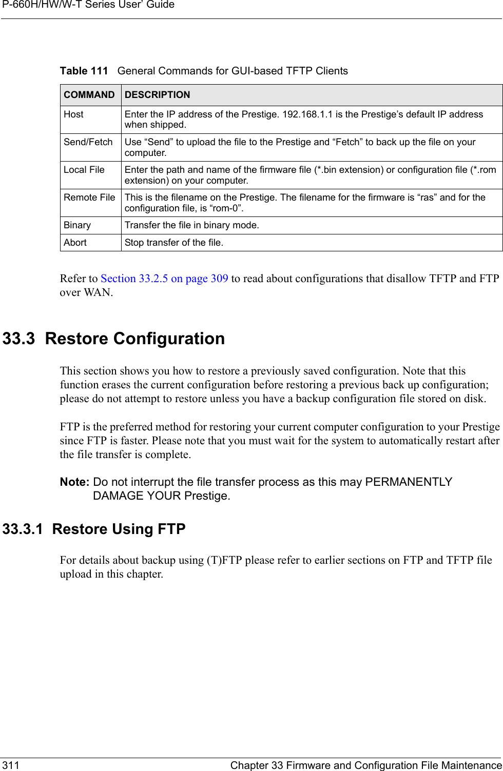
![P-660H/HW/W-T Series User’ GuideChapter 33 Firmware and Configuration File Maintenance 312Figure 199 Telnet into Menu 24.61Launch the FTP client on your computer.2Enter “open”, followed by a space and the IP address of your Prestige. 3Press [ENTER] when prompted for a username.4Enter your password as requested (the default is “1234”).5Enter “bin” to set transfer mode to binary.6Find the “rom” file (on your computer) that you want to restore to your Prestige.7Use “put” to transfer files from the Prestige to the computer, for example, “put config.rom rom-0” transfers the configuration file “config.rom” on your computer to the Prestige. See earlier in this chapter for more information on filename conventions.8Enter “quit” to exit the ftp prompt. The Prestige will automatically restart after a successful restore process.33.3.2 Restore Using FTP Session ExampleFigure 200 Restore Using FTP Session ExampleRefer to Section 33.2.5 on page 309 to read about configurations that disallow TFTP and FTP over WAN.Menu 24.6 -- System Maintenance - Restore ConfigurationTo transfer the firmware and configuration file to your workstation, follow the procedure below:1. Launch the FTP client on your workstation.2. Type "open" and the IP address of your Prestige. Then type "root" and SMT password as requested.3. Type "put backupfilename rom-0" where backupfilename is the name of your backup configuration file on your workstation and rom-0 is the remote file name on the Prestige. This restores the configuration to your Prestige.4. The system reboots automatically after a successful file transferFor details on FTP commands, please consult the documentation of your FTP client program. For details on backup using TFTP (note that you must remain in this menu to back up using TFTP), please see your Prestige manual.Press ENTER to Exit:ftp> put config.rom rom-0200 Port command okay150 Opening data connection for STOR rom-0226 File received OK221 Goodbye for writing flashftp: 16384 bytes sent in 0.06Seconds 273.07Kbytes/sec.ftp>quit](https://usermanual.wiki/ZyXEL-Communications/P660HWTX.Users-Manual-4/User-Guide-566053-Page-12.png)
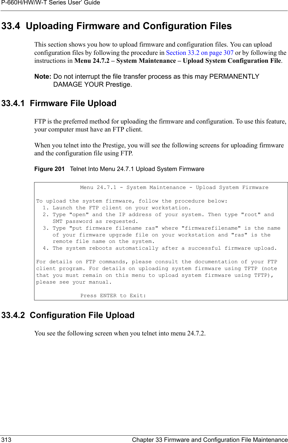
![P-660H/HW/W-T Series User’ GuideChapter 33 Firmware and Configuration File Maintenance 314Figure 202 Telnet Into Menu 24.7.2 System Maintenance To upload the firmware and the configuration file, follow these examples33.4.3 FTP File Upload Command from the DOS Prompt Example1Launch the FTP client on your computer.2Enter “open”, followed by a space and the IP address of your Prestige. 3Press [ENTER] when prompted for a username.4Enter your password as requested (the default is “1234”).5Enter “bin” to set transfer mode to binary.6Use “put” to transfer files from the computer to the Prestige, for example, “put firmware.bin ras” transfers the firmware on your computer (firmware.bin) to the Prestige and renames it “ras”. Similarly, “put config.rom rom-0” transfers the configuration file on your computer (config.rom) to the Prestige and renames it “rom-0”. Likewise “get rom-0 config.rom” transfers the configuration file on the Prestige to your computer and renames it “config.rom.” See earlier in this chapter for more information on filename conventions.7Enter “quit” to exit the ftp prompt.The Prestige automatically restarts after a successful file upload.Menu 24.7.2 - System Maintenance - Upload System Configuration FileTo upload the system configuration file, follow the procedure below: 1. Launch the FTP client on your workstation. 2. Type "open" and the IP address of your system. Then type "root" and SMT password as requested. 3. Type "put configuration filename rom-0" where "configurationfilename" is the name of your system configuration file on your workstation, which will be transferred to the "rom-0" file on the system. 4. The system reboots automatically after the upload system configuration file process is complete.For details on FTP commands, please consult the documentation of your FTPclient program. For details on uploading system firmware using TFTP (notethat you must remain on this menu to upload system firmware using TFTP),please see your manual.Press ENTER to Exit:](https://usermanual.wiki/ZyXEL-Communications/P660HWTX.Users-Manual-4/User-Guide-566053-Page-14.png)
![P-660H/HW/W-T Series User’ GuideChapter 33 Firmware and Configuration File Maintenance 31633.4.6 TFTP Upload Command ExampleThe following is an example TFTP command:tftp [-i] host put firmware.bin raswhere “i” specifies binary image transfer mode (use this mode when transferring binary files), “host” is the Prestige’s IP address and “put” transfers the file source on the computer (firmware.bin – name of the firmware on the computer) to the file destination on the remote host (ras - name of the firmware on the Prestige).Commands that you may see in GUI-based TFTP clients are listed earlier in this chapter.](https://usermanual.wiki/ZyXEL-Communications/P660HWTX.Users-Manual-4/User-Guide-566053-Page-16.png)
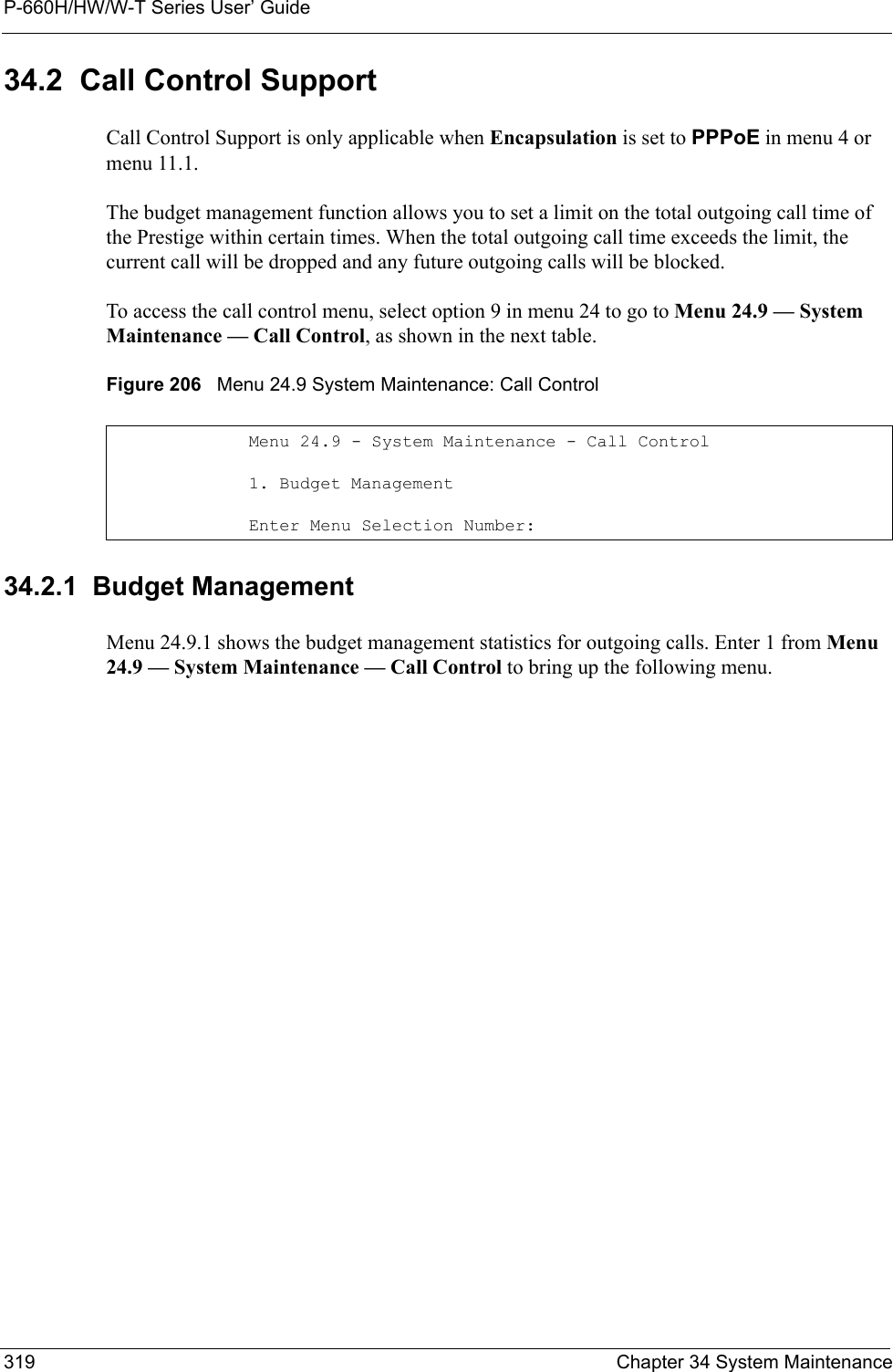
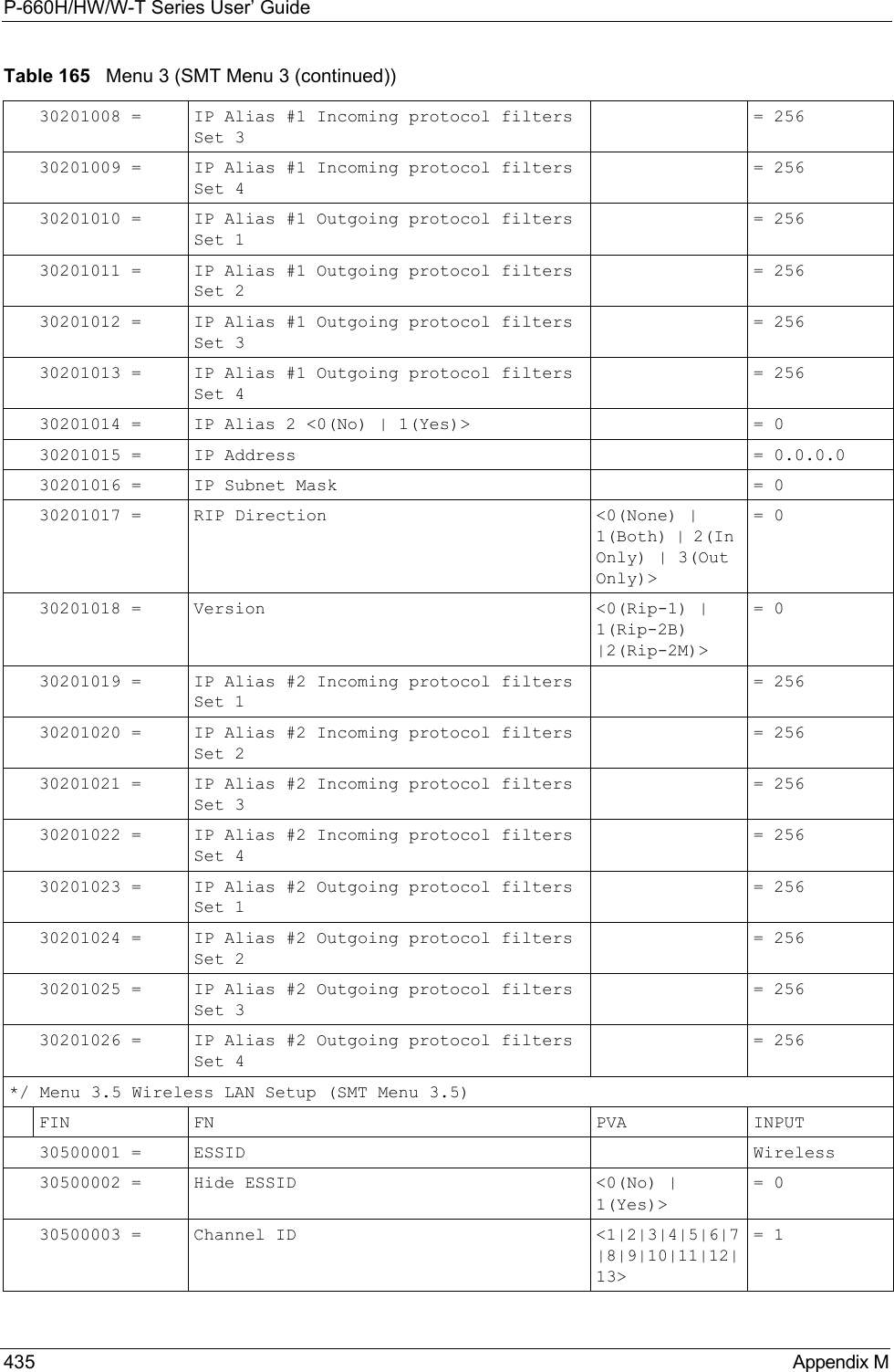
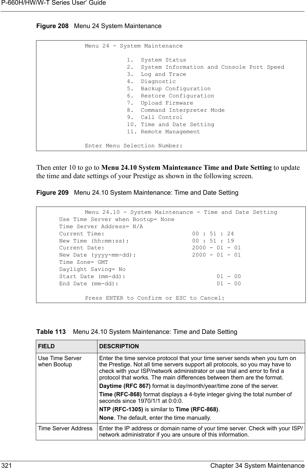
![P-660H/HW/W-T Series User’ GuideChapter 34 System Maintenance 320Figure 207 Menu 24.9.1 System Maintenance: Budget ManagementThe total budget is the time limit on the accumulated time for outgoing calls to a remote node. When this limit is reached, the call will be dropped and further outgoing calls to that remote node will be blocked. After each period, the total budget is reset. The default for the total budget is 0 minutes and the period is 0 hours, meaning no budget control. You can reset the accumulated connection time in this menu by entering the index of a remote node. Enter 0 to update the screen. The budget and the reset period can be configured in menu 11.1 for the remote node when PPPoE encapsulation is selected. 34.3 Time and Date Setting The Prestige keeps track of the time and date. There is also a software mechanism to set the time manually or get the current time and date from an external server when you turn on your Prestige. Menu 24.10 allows you to update the time and date settings of your Prestige. The real time is then displayed in the Prestige error logs and firewall logs. Select menu 24 in the main menu to open Menu 24 System Maintenance, as shown next. Menu 24.9.1 - System Maintenance - Budget ManagementRemote Node1.MyIsp2.--------3.--------4.--------5.--------6.--------7.--------8.--------Connection Time/Total BudgetNo Budget---------------------Elapsed Time/Total PeriodNo Budget---------------------Reset Node (0 to update screen):Table 112 Menu 24.9.1 System Maintenance: Budget ManagementFIELD DESCRIPTIONRemote Node Enter the index number of the remote node you want to reset (just one in this case)Connection Time/Total BudgetThis is the total connection time that has gone by (within the allocated budget that you set in menu 11.1.Elapsed Time/Total Period The period is the time cycle in hours that the allocation budget is reset (see menu 11.1.) The elapsed time is the time used up within this period.Enter “0” to update the screen or press [ESC] to return to the previous screen.](https://usermanual.wiki/ZyXEL-Communications/P660HWTX.Users-Manual-4/User-Guide-566053-Page-20.png)
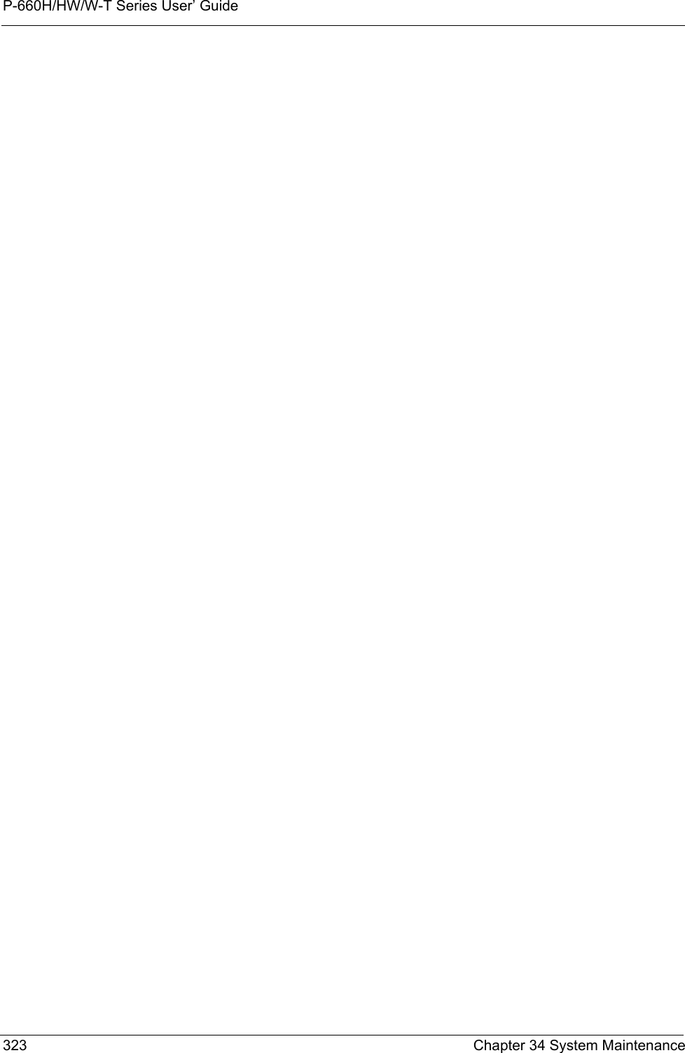
![P-660H/HW/W-T Series User’ GuideChapter 34 System Maintenance 32234.3.1 Resetting the Time• The Prestige resets the time in three instances:• On leaving menu 24.10 after making changes. • When the Prestige starts up, if there is a timeserver configured in menu 24.10.• 24-hour intervals after starting.Current Time This field displays an updated time only when you reenter this menu.New Time Enter the new time in hour, minute and second format.Current Date This field displays an updated date only when you re-enter this menu.New Date Enter the new date in year, month and day format.Time Zone Press [SPACE BAR] and then [ENTER] to set the time difference between your time zone and Greenwich Mean Time (GMT). Daylight Saving If you use daylight savings time, then choose Yes.Start Date If using daylight savings time, enter the month and day that it starts on.End Date If using daylight savings time, enter the month and day that it ends onWhen you have completed this menu, press [ENTER] at the prompt “Press ENTER to Confirm or ESC to Cancel:” to save your configuration, or press [ESC] at any time to cancel.Table 113 Menu 24.10 System Maintenance: Time and Date Setting (continued)FIELD DESCRIPTION](https://usermanual.wiki/ZyXEL-Communications/P660HWTX.Users-Manual-4/User-Guide-566053-Page-22.png)
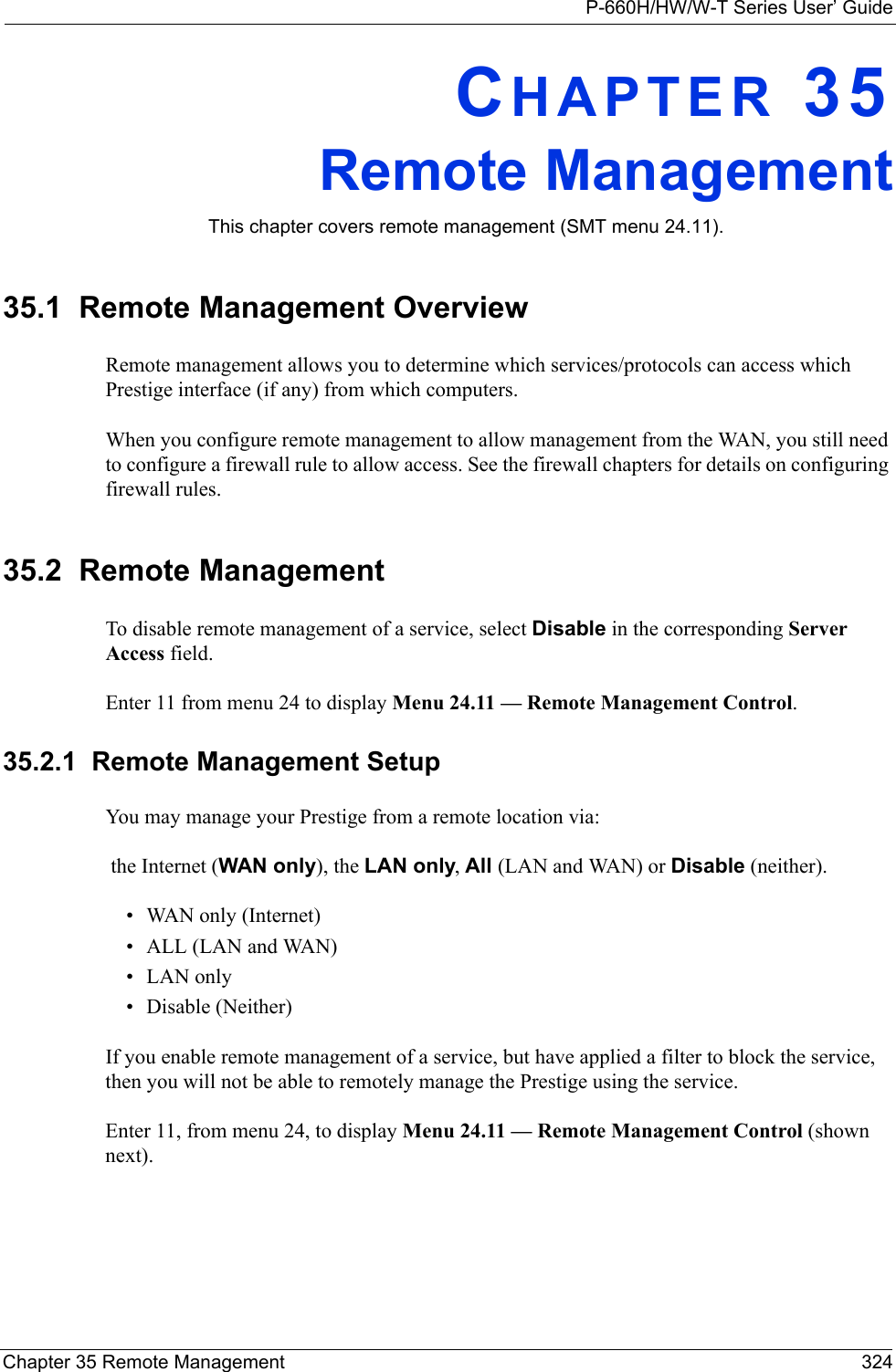
![P-660H/HW/W-T Series User’ Guide325 Chapter 35 Remote ManagementFigure 210 Menu 24.11 Remote Management ControlThe following table describes the fields in this menu.35.2.2 Remote Management LimitationsRemote management over LAN or WAN will not work when:• A filter in menu 3.1 (LAN) or in menu 11.5 (WAN) is applied to block a Telnet, FTP or Web service. • You have disabled that service in menu 24.11.• The IP address in the Secured Client IP field (menu 24.11) does not match the client IP address. If it does not match, the Prestige will disconnect the session immediately.• There is already another remote management session with an equal or higher priority running. You may only have one remote management session running at one time.• There is a firewall rule that blocks it.Menu 24.11 - Remote Management Control TELNET Server: Server Port = 23 Server Access = LAN only Secured Client IP = 0.0.0.0 FTP Server: Server Port = 21 Server Access = LAN only Secured Client IP = 0.0.0.0 Web Server: Server Port = 80 Server Access = LAN only Secured Client IP = 0.0.0.0Press ENTER to Confirm or ESC to Cancel:Table 114 Menu 24.11 Remote Management ControlFIELD DESCRIPTIONTelnet ServerFTP Server Web Server Each of these read-only labels denotes a service or protocol.Port This field shows the port number for the service or protocol. You may change the port number if needed, but you must use the same port number to access the Prestige.Access Select the access interface (if any) by pressing the [SPACE BAR]. Choices are: LAN only, WAN only, All or Disable. The default is LAN only.Secured Client IP The default 0.0.0.0 allows any client to use this service or protocol to access the Prestige. Enter an IP address to restrict access to a client with a matching IP address.When you have completed this menu, press [ENTER] at the prompt “Press ENTER to Confirm or ESC to Cancel:” to save your configuration, or press [ESC] at any time to cancel.](https://usermanual.wiki/ZyXEL-Communications/P660HWTX.Users-Manual-4/User-Guide-566053-Page-25.png)
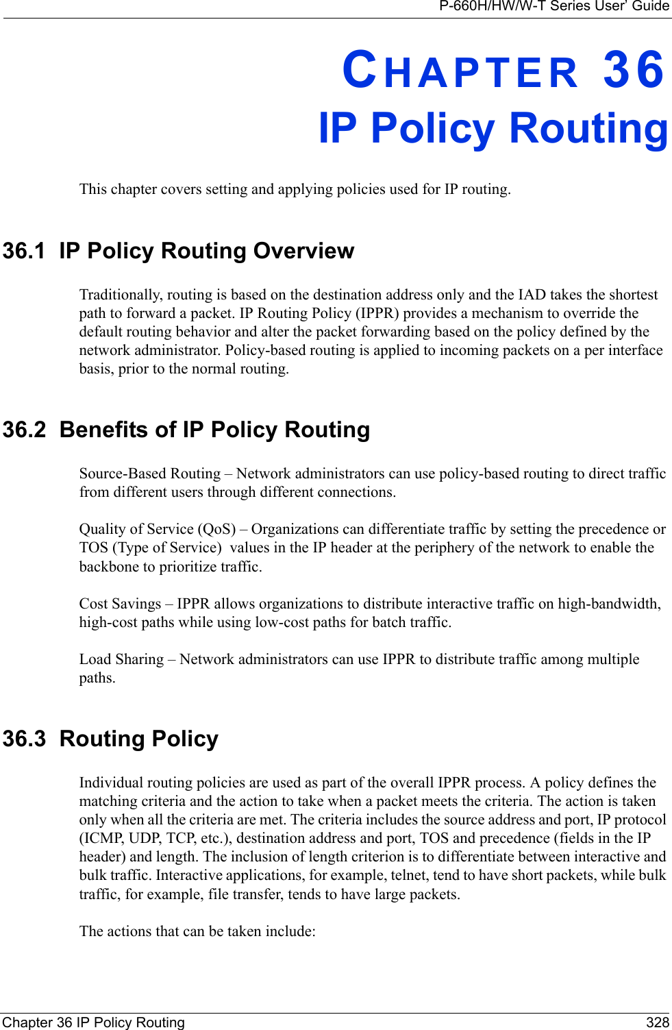
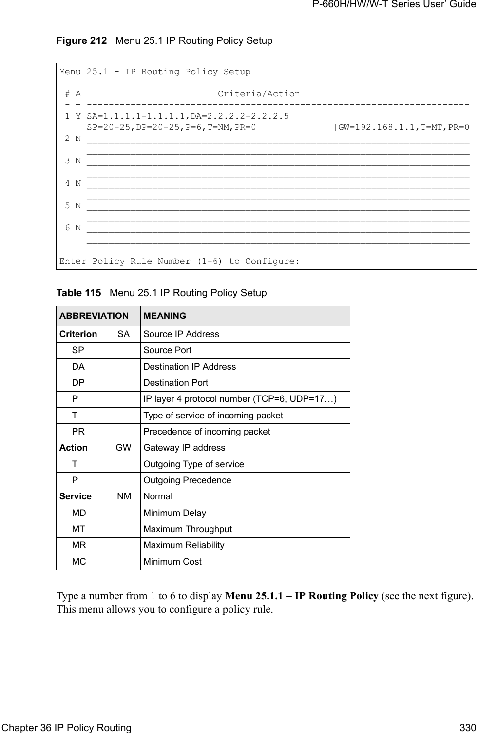
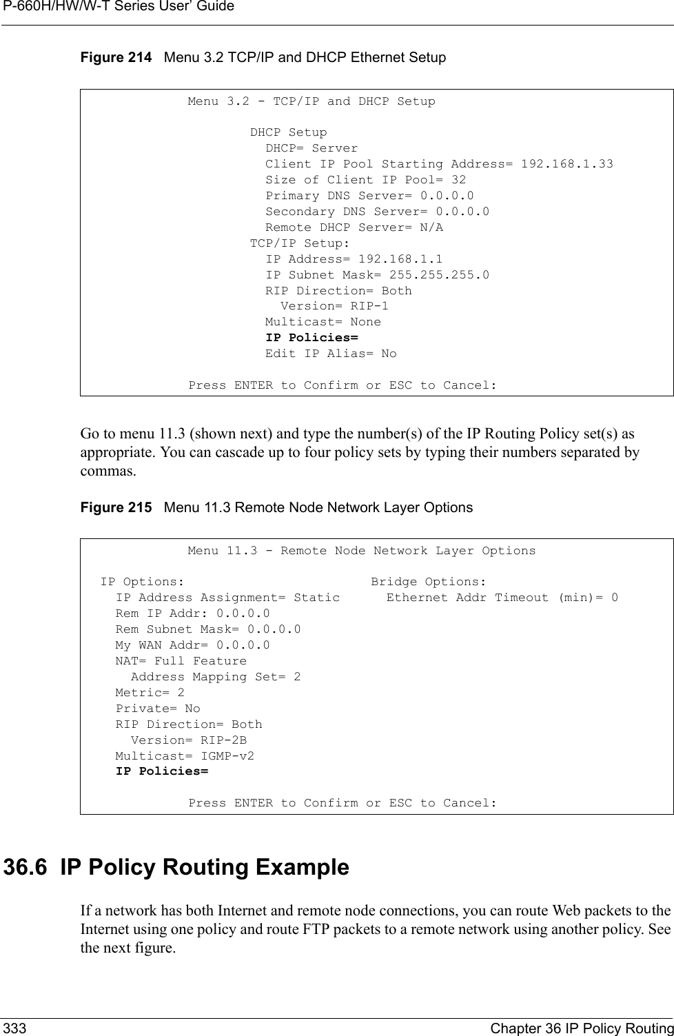
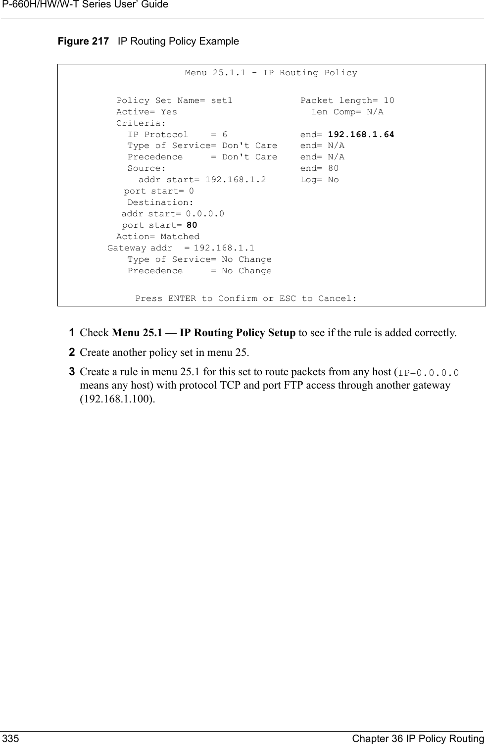
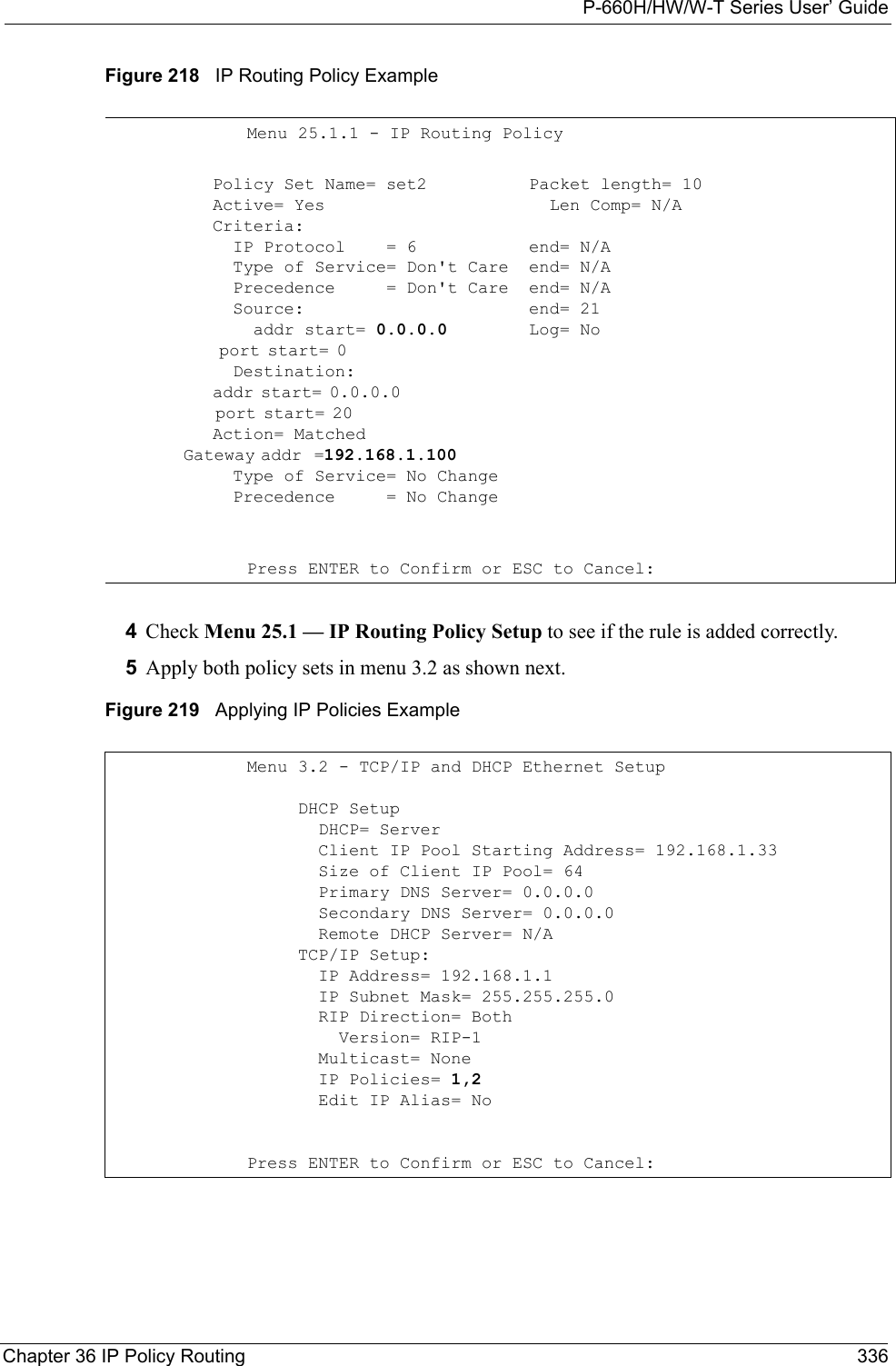
![P-660H/HW/W-T Series User’ Guide331 Chapter 36 IP Policy RoutingFigure 213 Menu 25.1.1 IP Routing PolicyThe following table describes the fields in this menu.Menu 25.1.1 - IP Routing Policy Policy Set Name= test Active= No Criteria: IP Protocol = 0 Type of Service= Don't Care Packet length= 0 Precedence = Don't Care Len Comp= N/A Source: addr start= 0.0.0.0 end= N/A port start= N/A end= N/A Destination: addr start= 0.0.0.0 end= N/A port start= N/A end= N/A Action= Matched Gateway addr = 0.0.0.0 Log= No Type of Service= No Change Precedence = No ChangePress ENTER to Confirm or ESC to Cancel:Table 116 Menu 25.1.1 IP Routing PolicyFIELD DESCRIPTIONPolicy Set Name This is the policy set name assigned in Menu 25 – IP Routing Policy Setup.Active Press [SPACE BAR] and then [ENTER] to select Yes to activate or No to deactivate the policy. Inactive policies are displayed with a minus sign “-“ in SMT menu 25.CriteriaIP Protocol IP layer 4 protocol, for example, UDP, TCP, ICMP, etc.Type of Service Prioritize incoming network traffic by choosing from Don’t Care, Normal, Min Delay, Max Thruput, Min Cost or Max Reliable.Precedence Precedence value of the incoming packet. Press [SPACE BAR] and then [ENTER] to select a value from 0 to 7 or Don’t Care.Packet Length Type the length of incoming packets (in bytes). The operators in the Len Comp (next field) apply to packets of this length.Len Comp Press [SPACE BAR] and then [ENTER] to choose from Equal, Not Equal, Less, Greater, Less or Equal or Greater or Equal.Source:addr start / end Source IP address range from start to end.port start / end Source port number range from start to end; applicable only for TCP/UDP.Destination:addr start / end Destination IP address range from start to end.port start / end Destination port number range from start to end; applicable only for TCP/UDP.Action Specifies whether action should be taken on criteria Matched or Not Matched.](https://usermanual.wiki/ZyXEL-Communications/P660HWTX.Users-Manual-4/User-Guide-566053-Page-31.png)
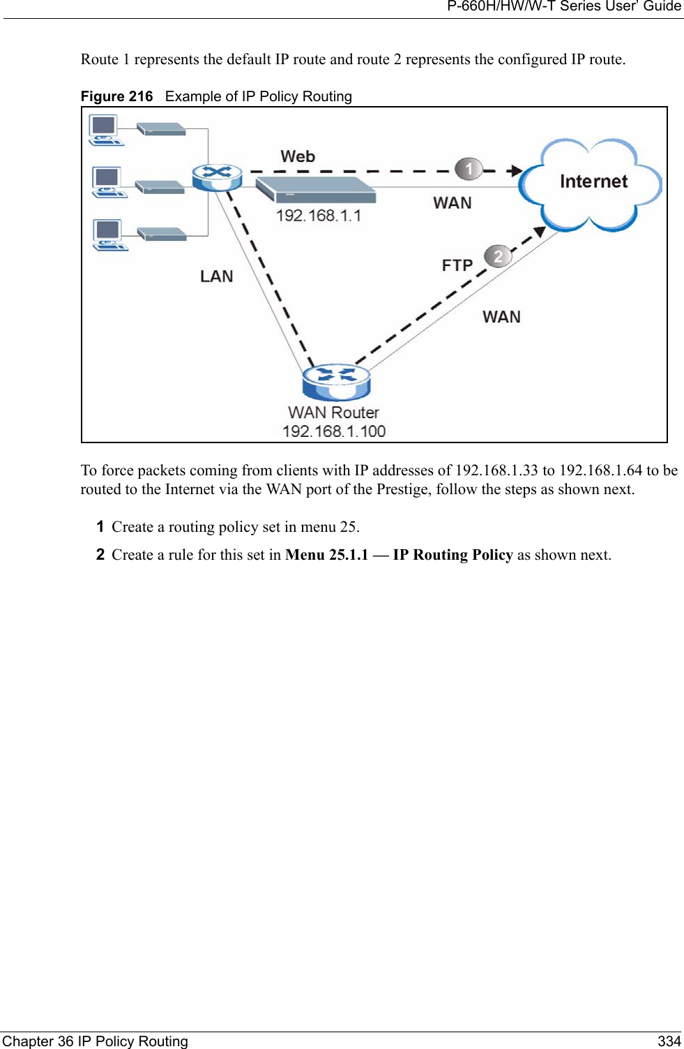
![P-660H/HW/W-T Series User’ GuideChapter 36 IP Policy Routing 33236.5 Applying an IP PolicyThis section shows you where to apply the IP policies after you design them.36.5.1 Ethernet IP PoliciesFrom Menu 3 — Ethernet Setup, type 2 to go to Menu 3.2 — TCP/IP and DHCP Ethernet Setup.You can choose up to four IP policy sets (from 12) by typing their numbers separated by commas, for example, 2, 4, 7, 9.Gateway addr Defines the outgoing gateway address. The gateway must be on the same subnet as the Prestige if it is on the LAN, otherwise, the gateway must be the IP address of a remote node. The default gateway is specified as 0.0.0.0.Type of Service Set the new TOS value of the outgoing packet. Prioritize incoming network traffic by choosing No Change, Normal, Min Delay, Max Thruput, Max Reliable or Min Cost.Precedence Set the new outgoing packet precedence value. Values are 0 to 7 or No Change.Log Press [SPACE BAR] and then [ENTER] to select Yes to make an entry in the system log when a policy is executed.When you have completed this menu, press [ENTER] at the prompt “Press ENTER to Confirm or ESC to Cancel:” to save your configuration, or press [ESC] at any time to cancel.Table 116 Menu 25.1.1 IP Routing Policy (continued)FIELD DESCRIPTION](https://usermanual.wiki/ZyXEL-Communications/P660HWTX.Users-Manual-4/User-Guide-566053-Page-32.png)

![P-660H/HW/W-T Series User’ GuideChapter 37 Call Scheduling 338CHAPTER 37Call SchedulingCall scheduling (applicable for PPPoA or PPPoE encapsulation only) allows you to dictate when a remote node should be called and for how long.37.1 IntroductionThe call scheduling feature allows the Prestige to manage a remote node and dictate when a remote node should be called and for how long. This feature is similar to the scheduler in a videocassette recorder (you can specify a time period for the VCR to record). You can apply up to 4 schedule sets in Menu 11.1 — Remote Node Profile. From the main menu, enter 26 to access Menu 26 — Schedule Setup as shown next. Figure 220 Menu 26 Schedule SetupLower numbered sets take precedence over higher numbered sets thereby avoiding scheduling conflicts. For example, if sets 1, 2 ,3 and 4 in are applied in the remote node then set 1 will take precedence over set 2, 3 and 4 as the Prestige, by default, applies the lowest numbered set first. Set 2 will take precedence over set 3 and 4, and so on.You can design up to 12 schedule sets but you can only apply up to four schedule sets for a remote node.To delete a schedule set, enter the set number and press [SPACE BAR] and then [ENTER] (or delete) in the Edit Name field.Menu 26 - Schedule Setup Schedule Set # Name Set # Name ------ ----------------- ------ ----------------- 1 _______________ 7 _______________ 2 _______________ 8 _______________ 3 _______________ 9 _______________ 4 _______________ 10 _______________ 5 _______________ 11 _______________ 6 _______________ 12 _______________Enter Schedule Set Number to Configure= 0Edit Name= N/APress ENTER to Confirm or ESC to Cancel:](https://usermanual.wiki/ZyXEL-Communications/P660HWTX.Users-Manual-4/User-Guide-566053-Page-38.png)
![P-660H/HW/W-T Series User’ Guide339 Chapter 37 Call Scheduling To setup a schedule set, select the schedule set you want to setup from menu 26 (1-12) and press [ENTER] to see Menu 26.1 — Schedule Set Setup as shown next. Figure 221 Menu 26.1 Schedule Set SetupIf a connection has been already established, your Prestige will not drop it. Once the connection is dropped manually or it times out, then that remote node can't be triggered up until the end of the Duration. Menu 26.1 Schedule Set Setup Active= Yes Start Date(yyyy-mm-dd)= 2000 - 01 - 01 How Often= Once Once: Date(yyyy-mm-dd)= 2000 - 01 - 01 Weekdays: Sunday= N/A Monday= N/A Tuesday= N/A Wednesday= N/A Thursday= N/A Friday= N/A Saturday= N/A Start Time(hh:mm)= 00: 00 Duration(hh:mm)= 00: 00 Action= Forced OnPress ENTER to Confirm or ESC to Cancel:Table 117 Menu 26.1 Schedule Set SetupFIELD DESCRIPTIONActive Press [SPACE BAR] to select Yes or No. Choose Yes and press [ENTER] to activate the schedule set. Start Date Enter the start date when you wish the set to take effect in year -month-date format. Valid dates are from the present to 2036-February-5.How Often Should this schedule set recur weekly or be used just once only? Press the [SPACE BAR] and then [ENTER] to select Once or Weekly. Both these options are mutually exclusive. If Once is selected, then all weekday settings are N/A. When Once is selected, the schedule rule deletes automatically after the scheduled time elapses.Once: DateIf you selected Once in the How Often field above, then enter the date the set should activate here in year-month-date format.Weekday:DayIf you selected Weekly in the How Often field above, then select the day(s) when the set should activate (and recur) by going to that day(s) and pressing [SPACE BAR] to select Yes, then press [ENTER].Start Time Enter the start time when you wish the schedule set to take effect in hour-minute format. Duration Enter the maximum length of time this connection is allowed in hour-minute format.](https://usermanual.wiki/ZyXEL-Communications/P660HWTX.Users-Manual-4/User-Guide-566053-Page-39.png)
![P-660H/HW/W-T Series User’ GuideChapter 37 Call Scheduling 340Once your schedule sets are configured, you must then apply them to the desired remote node(s). Enter 11 from the Main Menu and then enter the target remote node index. Using [SPACE BAR], select PPPoE or PPPoA in the Encapsulation field and then press [ENTER] to make the schedule sets field available as shown next.Figure 222 Applying Schedule Set(s) to a Remote Node (PPPoE)You can apply up to four schedule sets, separated by commas, for one remote node. Change the schedule set numbers to your preference(s).Action Forced On means that the connection is maintained whether or not there is a demand call on the line and will persist for the time period specified in the Duration field. Forced Down means that the connection is blocked whether or not there is a demand call on the line. Enable Dial-On-Demand means that this schedule permits a demand call on the line. Disable Dial-On-Demand means that this schedule prevents a demand call on the line. When you have completed this menu, press [ENTER] at the prompt “Press ENTER to Confirm or ESC to Cancel:” to save your configuration, or press [ESC] at any time to cancel.Menu 11.1 - Remote Node Profile Rem Node Name= MyISP Route= IP Active= Yes Bridge= No Encapsulation= PPPoA Edit IP/Bridge= No Multiplexing= LLC-based Edit ATM Options= No Service Name= N/A Edit Advance Options= N/A Incoming: Telco Option: Rem Login= Allocated Budget(min)= 0 Rem Password= ******** Period(hr)= 0 Outgoing: Schedule Sets= My Login= ChangeMe Nailed-Up Connection= No My Password= ******** Session Options: Authen= CHAP/PAP Edit Filter Sets= No Idle Timeout(sec)= 0Press ENTER to Confirm or ESC to Cancel:Table 117 Menu 26.1 Schedule Set Setup (continued)FIELD DESCRIPTION](https://usermanual.wiki/ZyXEL-Communications/P660HWTX.Users-Manual-4/User-Guide-566053-Page-40.png)
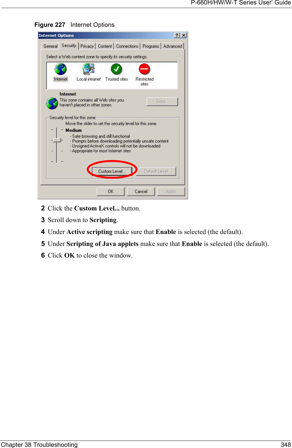


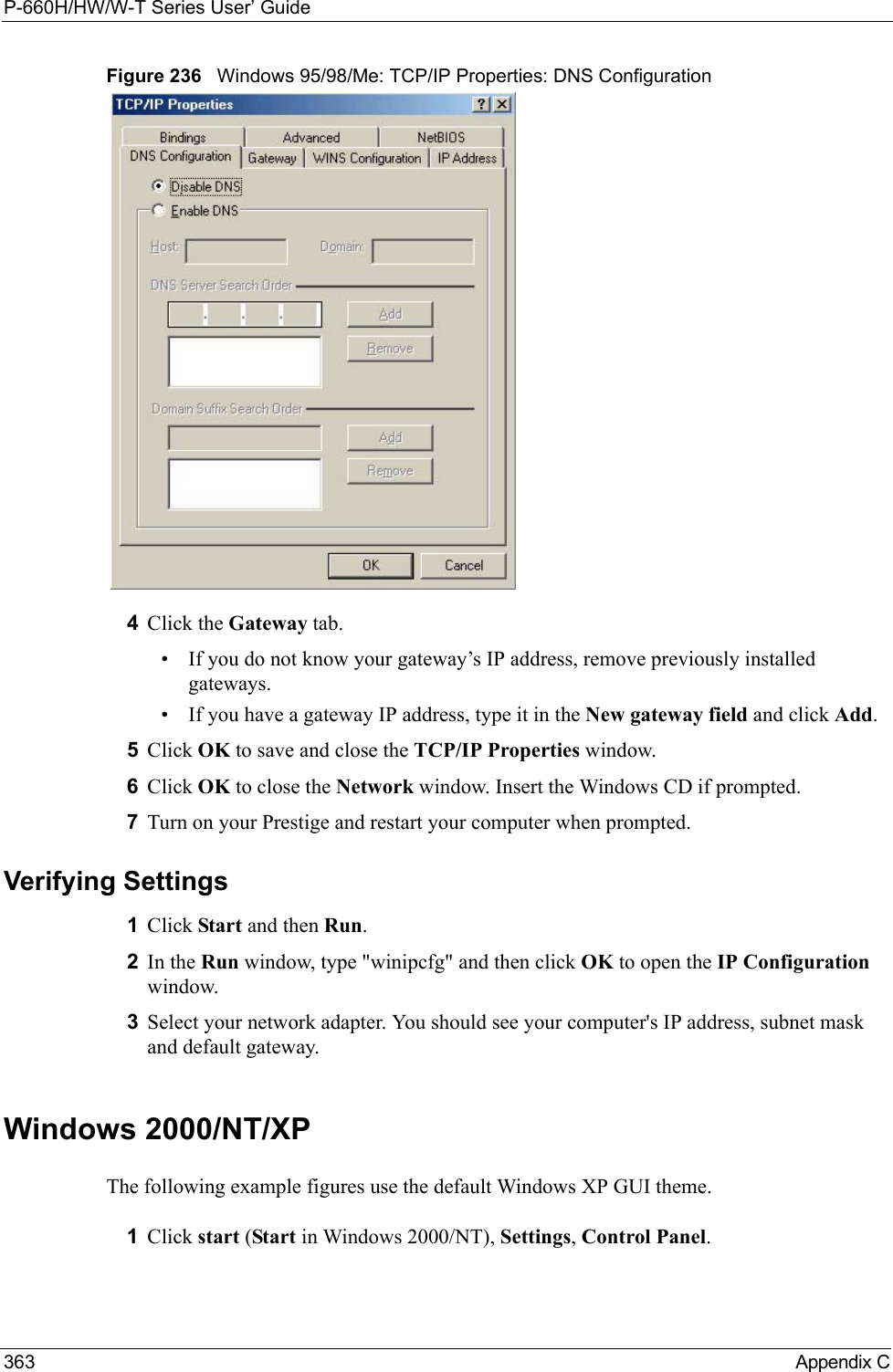
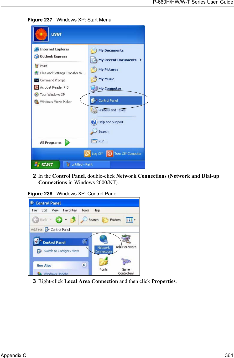
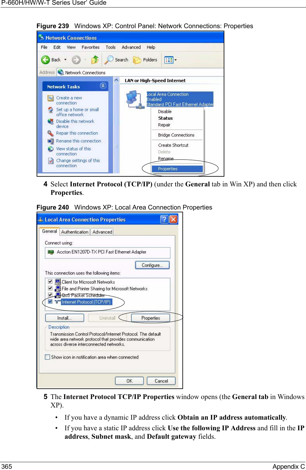
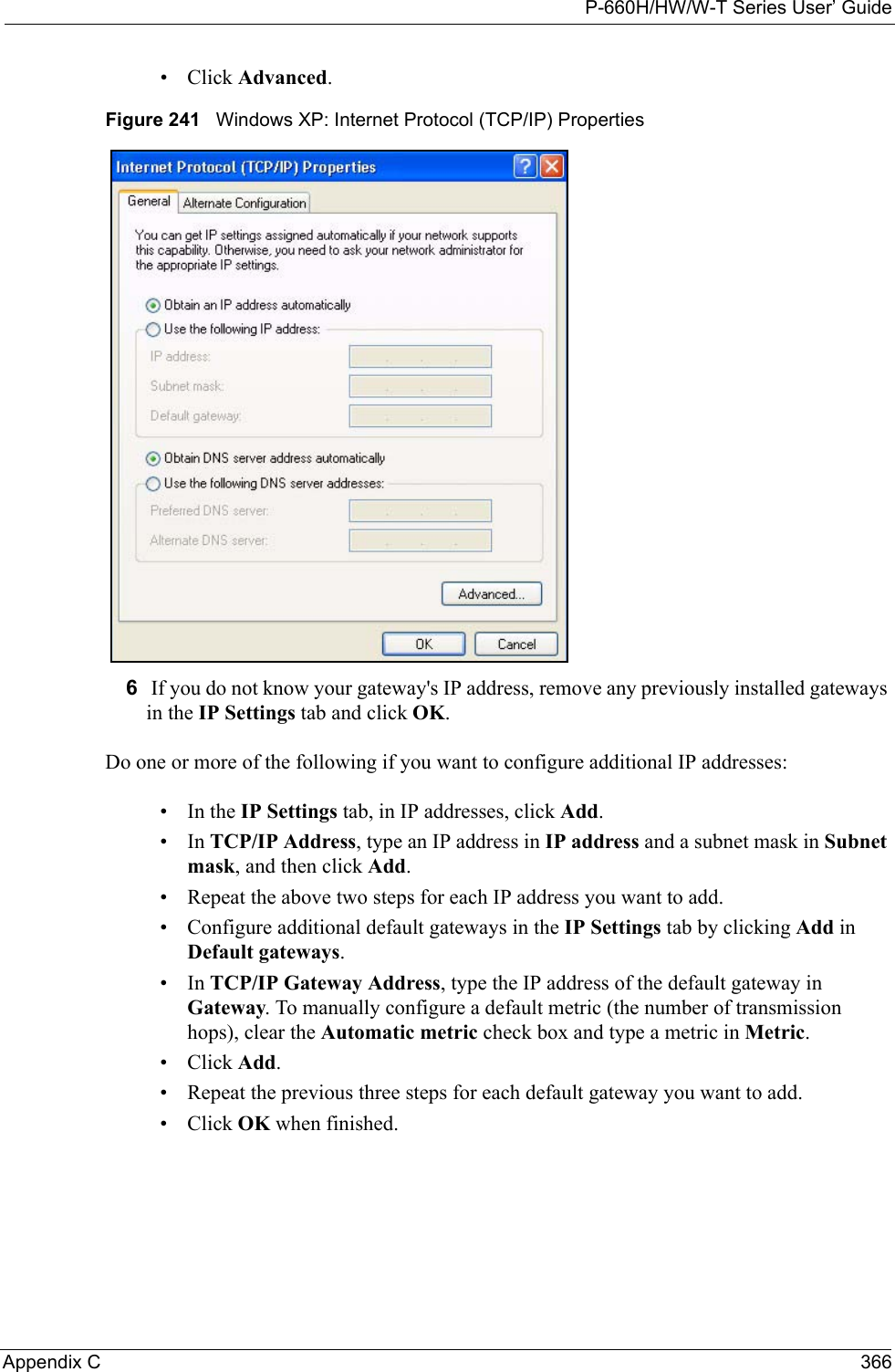
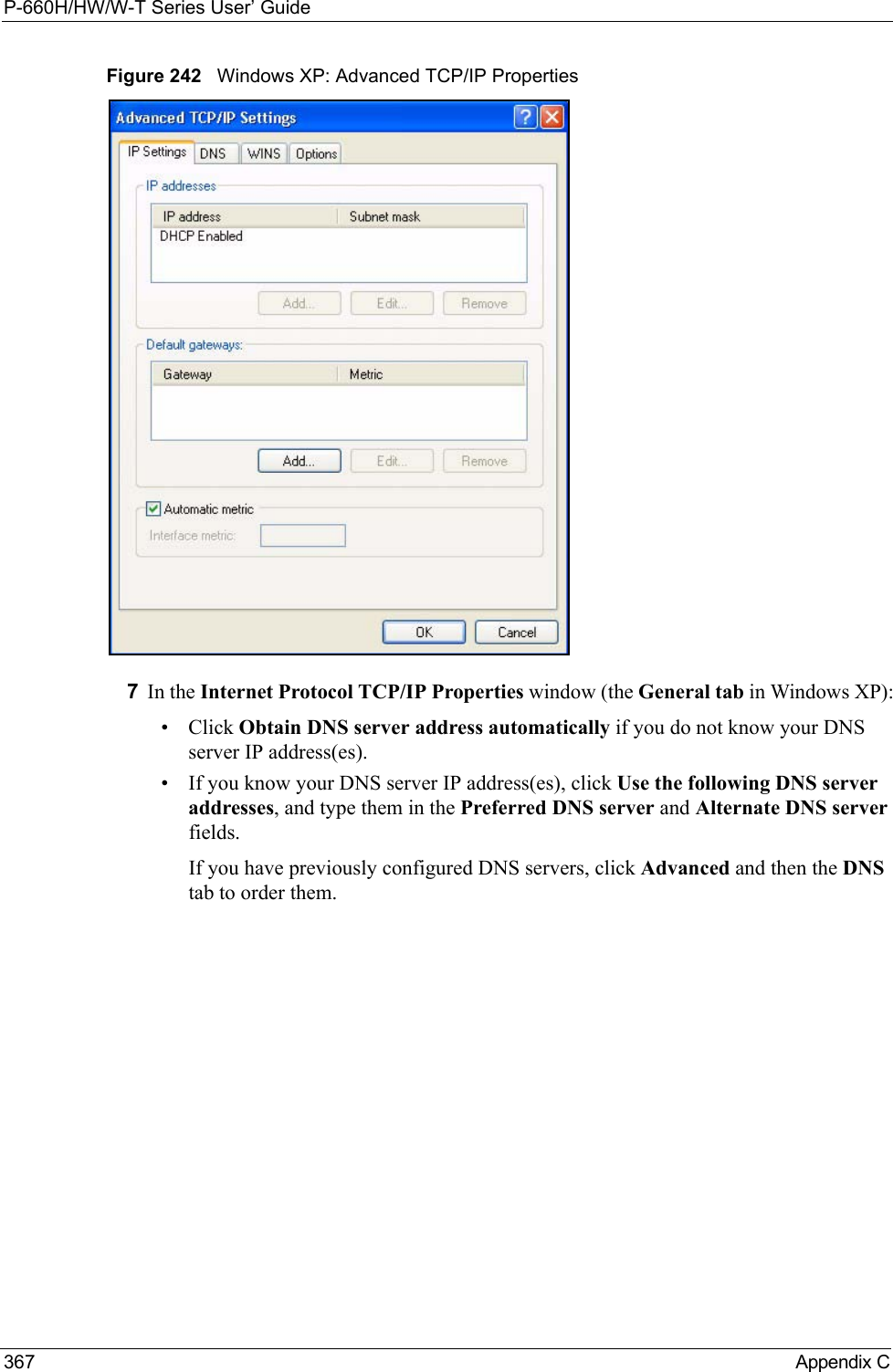
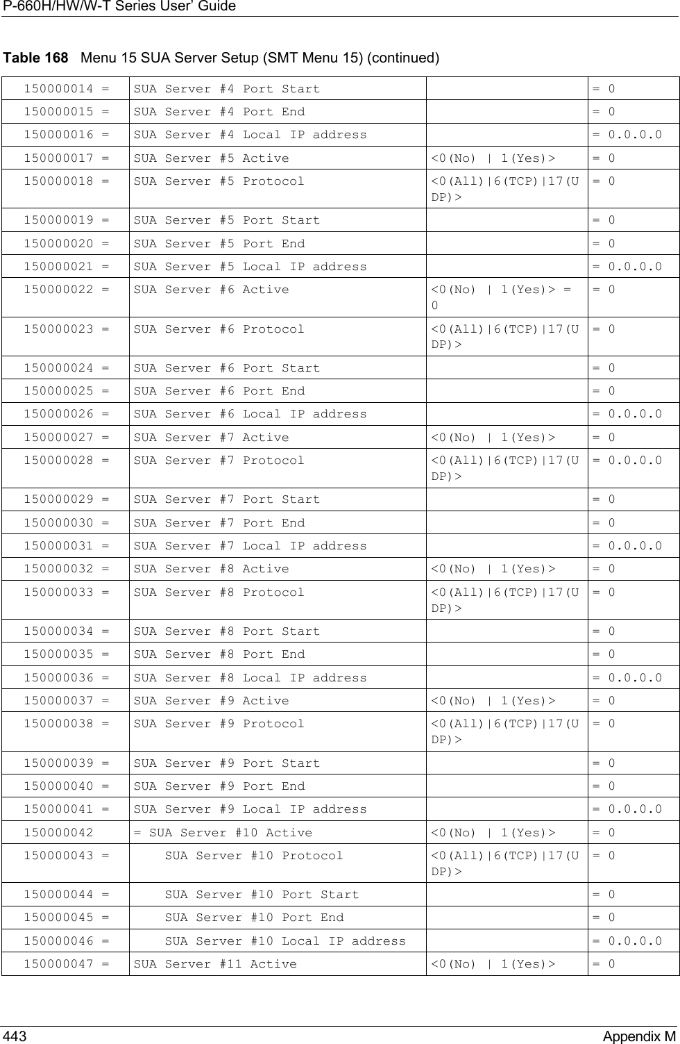
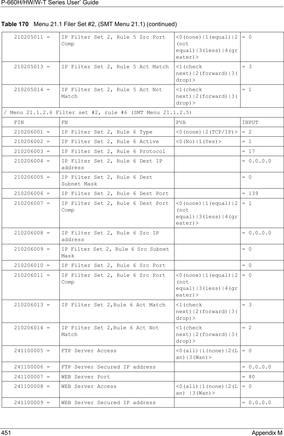
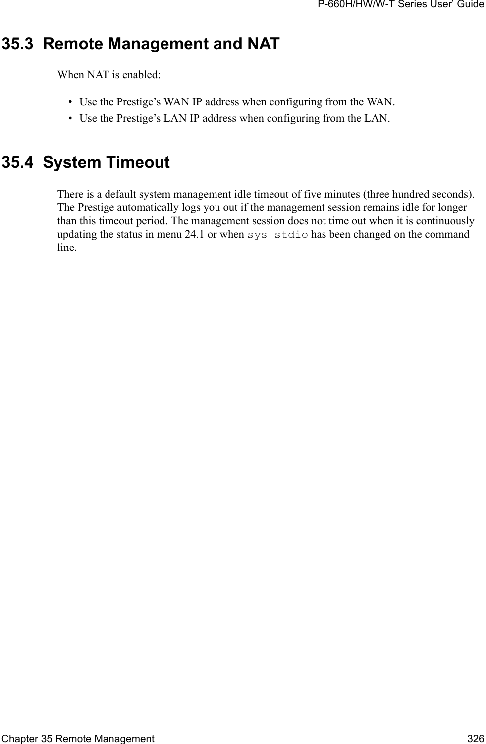
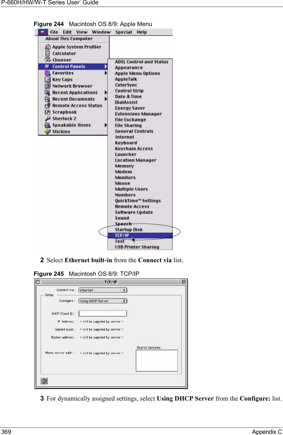
![P-660H/HW/W-T Series User’ GuideAppendix C 368Figure 243 Windows XP: Internet Protocol (TCP/IP) Properties8Click OK to close the Internet Protocol (TCP/IP) Properties window.9Click Close (OK in Windows 2000/NT) to close the Local Area Connection Properties window.10 Close the Network Connections window (Network and Dial-up Connections in Windows 2000/NT).11Turn on your Prestige and restart your computer (if prompted).Verifying Settings1Click Start, All Programs, Accessories and then Command Prompt.2In the Command Prompt window, type "ipconfig" and then press [ENTER]. You can also open Network Connections, right-click a network connection, click Status and then click the Support tab.Macintosh OS 8/9 1Click the Apple menu, Control Panel and double-click TCP/IP to open the TCP/IP Control Panel.](https://usermanual.wiki/ZyXEL-Communications/P660HWTX.Users-Manual-4/User-Guide-566053-Page-68.png)
![P-660H/HW/W-T Series User’ Guide375 Appendix CFigure 255 Red Hat 9.0: Restart Ethernet Card Verifying SettingsEnter ifconfig in a terminal screen to check your TCP/IP properties. Figure 256 Red Hat 9.0: Checking TCP/IP Properties [root@localhost init.d]# network restartShutting down interface eth0: [OK]Shutting down loopback interface: [OK]Setting network parameters: [OK]Bringing up loopback interface: [OK]Bringing up interface eth0: [OK][root@localhost]# ifconfig eth0 Link encap:Ethernet HWaddr 00:50:BA:72:5B:44 inet addr:172.23.19.129 Bcast:172.23.19.255 Mask:255.255.255.0 UP BROADCAST RUNNING MULTICAST MTU:1500 Metric:1 RX packets:717 errors:0 dropped:0 overruns:0 frame:0 TX packets:13 errors:0 dropped:0 overruns:0 carrier:0 collisions:0 txqueuelen:100 RX bytes:730412 (713.2 Kb) TX bytes:1570 (1.5 Kb) Interrupt:10 Base address:0x1000 [root@localhost]#](https://usermanual.wiki/ZyXEL-Communications/P660HWTX.Users-Manual-4/User-Guide-566053-Page-75.png)

![P-660H/HW/W-T Series User’ GuideAppendix F 386Appendix FCommand InterpreterThe following describes how to use the command interpreter. Enter 24 in the main menu to bring up the system maintenance menu. Enter 8 to go to Menu 24.8 - Command Interpreter Mode. See the included disk or zyxel.com for more detailed information on these commands.Note: Use of undocumented commands or misconfiguration can damage the unit and possibly render it unusable.Command Syntax• The command keywords are in courier new font.• Enter the command keywords exactly as shown, do not abbreviate.• The required fields in a command are enclosed in angle brackets <>. • The optional fields in a command are enclosed in square brackets [].•The |symbol means or.For example,sys filter netbios config <type> <on|off>means that you must specify the type of netbios filter and whether to turn it on or off.Command UsageA list of valid commands can be found by typing help or? at the command prompt. Always type the full command. Type exit to return to the SMT main menu when finished.](https://usermanual.wiki/ZyXEL-Communications/P660HWTX.Users-Manual-4/User-Guide-566053-Page-86.png)


![P-660H/HW/W-T Series User’ Guide405 Appendix K Configuration Change: PC = 0x%x, Task ID = 0x%xThe router is saving configuration changes.Successful SSH login Someone has logged on to the router’s SSH server.SSH login failed Someone has failed to log on to the router’s SSH server.Successful HTTPS login Someone has logged on to the router's web configurator interface using HTTPS protocol.HTTPS login failed Someone has failed to log on to the router's web configurator interface using HTTPS protocol.Table 141 System Error LogsLOG MESSAGE DESCRIPTION%s exceeds the max. number of session per host!This attempt to create a NAT session exceeds the maximum number of NAT session table entries allowed to be created per host.setNetBIOSFilter: calloc errorThe router failed to allocate memory for the NetBIOS filter settings.readNetBIOSFilter: calloc errorThe router failed to allocate memory for the NetBIOS filter settings.WAN connection is down. A WAN connection is down. You cannot access the network through this interface.Table 142 Access Control LogsLOG MESSAGE DESCRIPTIONFirewall default policy: [TCP | UDP | IGMP | ESP | GRE | OSPF] <Packet Direction>Attempted TCP/UDP/IGMP/ESP/GRE/OSPF access matched the default policy and was blocked or forwarded according to the default policy’s setting.Firewall rule [NOT] match:[TCP | UDP | IGMP | ESP | GRE | OSPF] <Packet Direction>, <rule:%d>Attempted TCP/UDP/IGMP/ESP/GRE/OSPF access matched (or did not match) a configured firewall rule (denoted by its number) and was blocked or forwarded according to the rule. Triangle route packet forwarded: [TCP | UDP | IGMP | ESP | GRE | OSPF]The firewall allowed a triangle route session to pass through.Packet without a NAT table entry blocked: [TCP | UDP | IGMP | ESP | GRE | OSPF]The router blocked a packet that didn't have a corresponding NAT table entry.Router sent blocked web site message: TCPThe router sent a message to notify a user that the router blocked access to a web site that the user requested.Table 140 System Maintenance Logs (continued)LOG MESSAGE DESCRIPTION](https://usermanual.wiki/ZyXEL-Communications/P660HWTX.Users-Manual-4/User-Guide-566053-Page-105.png)
![P-660H/HW/W-T Series User’ GuideAppendix K 406 Table 143 TCP Reset LogsLOG MESSAGE DESCRIPTIONUnder SYN flood attack, sent TCP RSTThe router sent a TCP reset packet when a host was under a SYN flood attack (the TCP incomplete count is per destination host.) Exceed TCP MAX incomplete, sent TCP RSTThe router sent a TCP reset packet when the number of TCP incomplete connections exceeded the user configured threshold. (the TCP incomplete count is per destination host.) Note: Refer to TCP Maximum Incomplete in the Firewall Attack Alerts screen. Peer TCP state out of order, sent TCP RSTThe router sent a TCP reset packet when a TCP connection state was out of order.Note: The firewall refers to RFC793 Figure 6 to check the TCP state.Firewall session time out, sent TCP RSTThe router sent a TCP reset packet when a dynamic firewall session timed out.The default timeout values are as follows:ICMP idle timeout: 3 minutesUDP idle timeout: 3 minutesTCP connection (three way handshaking) timeout: 270 secondsTCP FIN-wait timeout: 2 MSL (Maximum Segment Lifetime set in the TCP header).TCP idle (established) timeout (s): 150 minutesTCP reset timeout: 10 secondsExceed MAX incomplete, sent TCP RSTThe router sent a TCP reset packet when the number of incomplete connections (TCP and UDP) exceeded the user-configured threshold. (Incomplete count is for all TCP and UDP connections through the firewall.)Note: When the number of incomplete connections (TCP + UDP) > “Maximum Incomplete High”, the router sends TCP RST packets for TCP connections and destroys TOS (firewall dynamic sessions) until incomplete connections < “Maximum Incomplete Low”.Access block, sent TCP RSTThe router sends a TCP RST packet and generates this log if you turn on the firewall TCP reset mechanism (via CI command: "sys firewall tcprst").Table 144 Packet Filter LogsLOG MESSAGE DESCRIPTION[TCP | UDP | ICMP | IGMP | Generic] packet filter matched (set:%d, rule:%d)Attempted access matched a configured filter rule (denoted by its set and rule number) and was blocked or forwarded according to the rule.](https://usermanual.wiki/ZyXEL-Communications/P660HWTX.Users-Manual-4/User-Guide-566053-Page-106.png)
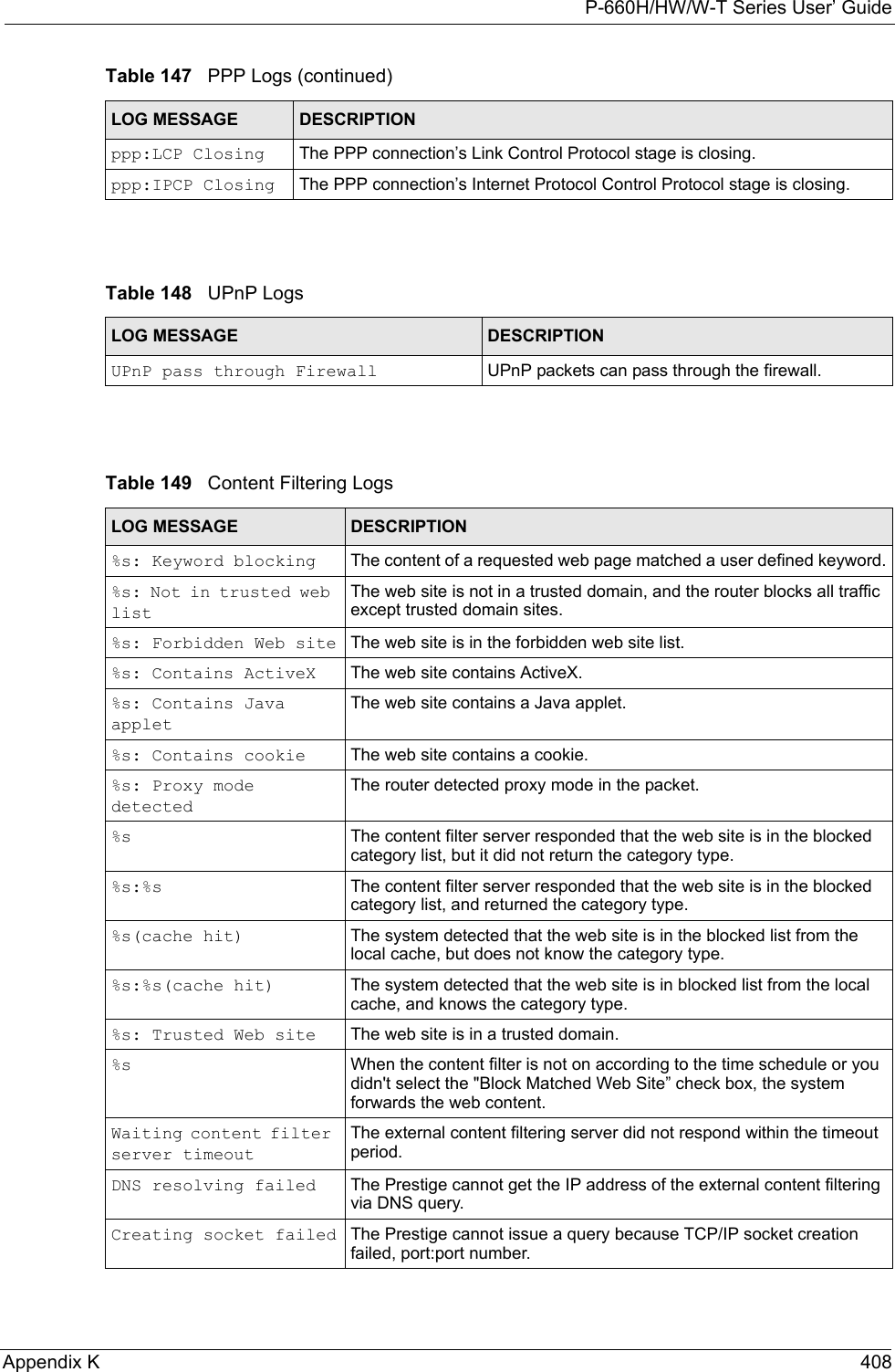
![P-660H/HW/W-T Series User’ Guide407 Appendix K Table 145 ICMP LogsLOG MESSAGE DESCRIPTIONFirewall default policy: ICMP <Packet Direction>, <type:%d>, <code:%d>ICMP access matched the default policy and was blocked or forwarded according to the user's setting. For type and code details, see Table 157 on page 416.Firewall rule [NOT] match: ICMP <Packet Direction>, <rule:%d>, <type:%d>, <code:%d>ICMP access matched (or didn’t match) a firewall rule (denoted by its number) and was blocked or forwarded according to the rule. For type and code details, see Table 157 on page 416.Triangle route packet forwarded: ICMPThe firewall allowed a triangle route session to pass through.Packet without a NAT table entry blocked: ICMPThe router blocked a packet that didn’t have a corresponding NAT table entry.Unsupported/out-of-order ICMP: ICMPThe firewall does not support this kind of ICMP packets or the ICMP packets are out of order.Router reply ICMP packet: ICMP The router sent an ICMP reply packet to the sender.Table 146 CDR LogsLOG MESSAGE DESCRIPTIONboard%d line%d channel%d, call%d,%s C01 Outgoing Call dev=%x ch=%x%sThe router received the setup requirements for a call. “call” is the reference (count) number of the call. “dev” is the device type (3 is for dial-up, 6 is for PPPoE, 10 is for PPTP). "channel" or “ch” is the call channel ID.For example,"board 0 line 0 channel 0, call 3, C01 Outgoing Call dev=6 ch=0 "Means the router has dialed to the PPPoE server 3 times.board%d line%d channel%d, call%d,%s C02 OutCall Connected%d%sThe PPPoE, PPTP or dial-up call is connected.board%d line%d channel%d, call%d,%s C02 Call TerminatedThe PPPoE, PPTP or dial-up call was disconnected.Table 147 PPP LogsLOG MESSAGE DESCRIPTIONppp:LCP Starting The PPP connection’s Link Control Protocol stage has started.ppp:LCP Opening The PPP connection’s Link Control Protocol stage is opening.ppp:CHAP Opening The PPP connection’s Challenge Handshake Authentication Protocol stage is opening.ppp:IPCP Starting The PPP connection’s Internet Protocol Control Protocol stage is starting.ppp:IPCP Opening The PPP connection’s Internet Protocol Control Protocol stage is opening.](https://usermanual.wiki/ZyXEL-Communications/P660HWTX.Users-Manual-4/User-Guide-566053-Page-107.png)
![P-660H/HW/W-T Series User’ Guide409 Appendix K Connecting to content filter server failThe connection to the external content filtering server failed.License key is invalid The external content filtering license key is invalid.Table 150 Attack LogsLOG MESSAGE DESCRIPTIONattack [TCP | UDP | IGMP | ESP | GRE | OSPF]The firewall detected a TCP/UDP/IGMP/ESP/GRE/OSPF attack.attack ICMP (type:%d, code:%d)The firewall detected an ICMP attack. For type and code details, see Table 157 on page 416.land [TCP | UDP | IGMP | ESP | GRE | OSPF]The firewall detected a TCP/UDP/IGMP/ESP/GRE/OSPF land attack.land ICMP (type:%d, code:%d)The firewall detected an ICMP land attack. For type and code details, see Table 157 on page 416.ip spoofing - WAN [TCP | UDP | IGMP | ESP | GRE | OSPF]The firewall detected an IP spoofing attack on the WAN port.ip spoofing - WAN ICMP (type:%d, code:%d)The firewall detected an ICMP IP spoofing attack on the WAN port. For type and code details, see Table 157 on page 416.icmp echo: ICMP (type:%d, code:%d)The firewall detected an ICMP echo attack. For type and code details, see Table 157 on page 416.syn flood TCP The firewall detected a TCP syn flood attack.ports scan TCP The firewall detected a TCP port scan attack.teardrop TCP The firewall detected a TCP teardrop attack.teardrop UDP The firewall detected an UDP teardrop attack.teardrop ICMP (type:%d, code:%d)The firewall detected an ICMP teardrop attack. For type and code details, see Table 157 on page 416.illegal command TCP The firewall detected a TCP illegal command attack.NetBIOS TCP The firewall detected a TCP NetBIOS attack.ip spoofing - no routing entry [TCP | UDP | IGMP | ESP | GRE | OSPF]The firewall classified a packet with no source routing entry as an IP spoofing attack.ip spoofing - no routing entry ICMP (type:%d, code:%d)The firewall classified an ICMP packet with no source routing entry as an IP spoofing attack.vulnerability ICMP (type:%d, code:%d)The firewall detected an ICMP vulnerability attack. For type and code details, see Table 157 on page 416.traceroute ICMP (type:%d, code:%d)The firewall detected an ICMP traceroute attack. For type and code details, see Table 157 on page 416.Table 149 Content Filtering Logs (continued)LOG MESSAGE DESCRIPTION](https://usermanual.wiki/ZyXEL-Communications/P660HWTX.Users-Manual-4/User-Guide-566053-Page-109.png)
![P-660H/HW/W-T Series User’ GuideAppendix K 412XAUTH fail! Username: <Username>The router was not able to use extended authentication to authenticate the listed username.Rule[%d] Phase 1 negotiation mode mismatchThe listed rule’s IKE phase 1 negotiation mode did not match between the router and the peer.Rule [%d] Phase 1 encryption algorithm mismatchThe listed rule’s IKE phase 1 encryption algorithm did not match between the router and the peer.Rule [%d] Phase 1 authentication algorithm mismatchThe listed rule’s IKE phase 1 authentication algorithm did not match between the router and the peer.Rule [%d] Phase 1 authentication method mismatchThe listed rule’s IKE phase 1 authentication method did not match between the router and the peer.Rule [%d] Phase 1 key group mismatchThe listed rule’s IKE phase 1 key group did not match between the router and the peer.Rule [%d] Phase 2 protocol mismatchThe listed rule’s IKE phase 2 protocol did not match between the router and the peer.Rule [%d] Phase 2 encryption algorithm mismatchThe listed rule’s IKE phase 2 encryption algorithm did not match between the router and the peer.Rule [%d] Phase 2 authentication algorithm mismatchThe listed rule’s IKE phase 2 authentication algorithm did not match between the router and the peer.Rule [%d] Phase 2 encapsulation mismatchThe listed rule’s IKE phase 2 encapsulation did not match between the router and the peer.Rule [%d]> Phase 2 pfs mismatchThe listed rule’s IKE phase 2 perfect forward secret (pfs) setting did not match between the router and the peer.Rule [%d] Phase 1 ID mismatch The listed rule’s IKE phase 1 ID did not match between the router and the peer.Rule [%d] Phase 1 hash mismatchThe listed rule’s IKE phase 1 hash did not match between the router and the peer.Rule [%d] Phase 1 preshared key mismatchThe listed rule’s IKE phase 1 pre-shared key did not match between the router and the peer.Rule [%d] Tunnel built successfullyThe listed rule’s IPSec tunnel has been built successfully.Rule [%d] Peer's public key not foundThe listed rule’s IKE phase 1 peer’s public key was not found.Rule [%d] Verify peer's signature failedThe listed rule’s IKE phase 1verification of the peer’s signature failed.Rule [%d] Sending IKE request IKE sent an IKE request for the listed rule.Rule [%d] Receiving IKE requestIKE received an IKE request for the listed rule.Swap rule to rule [%d] The router changed to using the listed rule.Rule [%d] Phase 1 key length mismatchThe listed rule’s IKE phase 1 key length (with the AES encryption algorithm) did not match between the router and the peer.Rule [%d] phase 1 mismatch The listed rule’s IKE phase 1 did not match between the router and the peer.Table 152 IKE Logs (continued)LOG MESSAGE DESCRIPTION](https://usermanual.wiki/ZyXEL-Communications/P660HWTX.Users-Manual-4/User-Guide-566053-Page-112.png)
![P-660H/HW/W-T Series User’ Guide413 Appendix K Rule [%d] phase 2 mismatch The listed rule’s IKE phase 2 did not match between the router and the peer.Rule [%d] Phase 2 key length mismatchThe listed rule’s IKE phase 2 key lengths (with the AES encryption algorithm) did not match between the router and the peer.Table 153 PKI LogsLOG MESSAGE DESCRIPTIONEnrollment successful The SCEP online certificate enrollment was successful. The Destination field records the certification authority server IP address and port.Enrollment failed The SCEP online certificate enrollment failed. The Destination field records the certification authority server’s IP address and port.Failed to resolve <SCEP CA server url>The SCEP online certificate enrollment failed because the certification authority server’s address cannot be resolved.Enrollment successful The CMP online certificate enrollment was successful. The Destination field records the certification authority server’s IP address and port.Enrollment failed The CMP online certificate enrollment failed. The Destination field records the certification authority server’s IP address and port.Failed to resolve <CMP CA server url>The CMP online certificate enrollment failed because the certification authority server’s IP address cannot be resolved.Rcvd ca cert: <subject name>The router received a certification authority certificate, with subject name as recorded, from the LDAP server whose IP address and port are recorded in the Source field.Rcvd user cert: <subject name>The router received a user certificate, with subject name as recorded, from the LDAP server whose IP address and port are recorded in the Source field.Rcvd CRL <size>: <issuer name>The router received a CRL (Certificate Revocation List), with size and issuer name as recorded, from the LDAP server whose IP address and port are recorded in the Source field.Rcvd ARL <size>: <issuer name>The router received an ARL (Authority Revocation List), with size and issuer name as recorded, from the LDAP server whose address and port are recorded in the Source field.Failed to decode the received ca certThe router received a corrupted certification authority certificate from the LDAP server whose address and port are recorded in the Source field.Failed to decode the received user certThe router received a corrupted user certificate from the LDAP server whose address and port are recorded in the Source field.Failed to decode the received CRLThe router received a corrupted CRL (Certificate Revocation List) from the LDAP server whose address and port are recorded in the Source field.Failed to decode the received ARLThe router received a corrupted ARL (Authority Revocation List) from the LDAP server whose address and port are recorded in the Source field.Table 152 IKE Logs (continued)LOG MESSAGE DESCRIPTION](https://usermanual.wiki/ZyXEL-Communications/P660HWTX.Users-Manual-4/User-Guide-566053-Page-113.png)
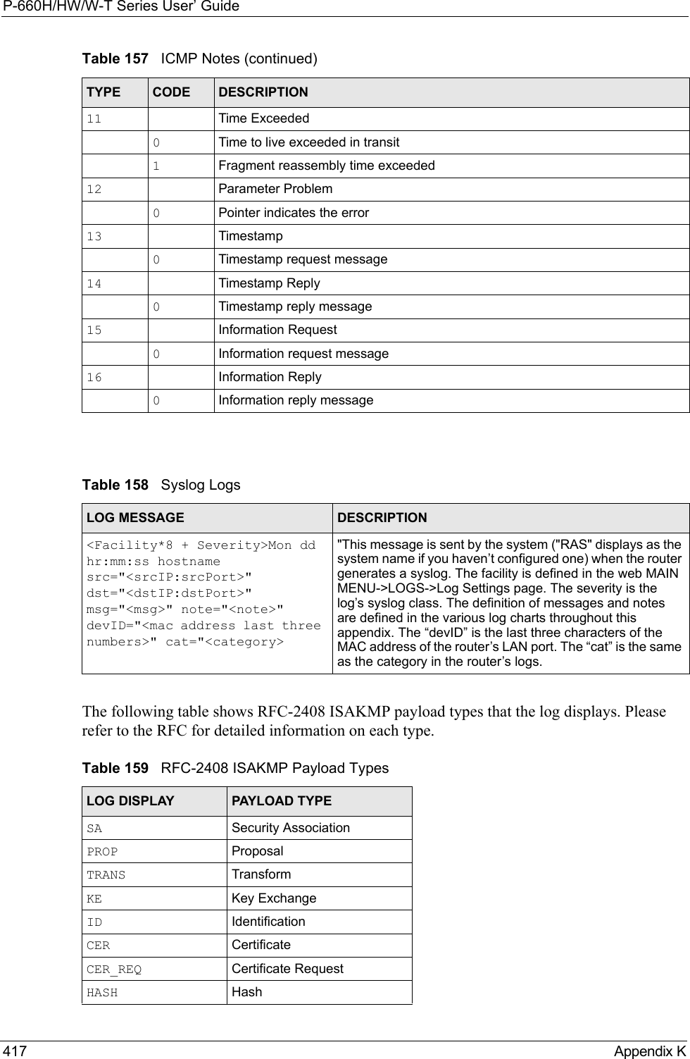
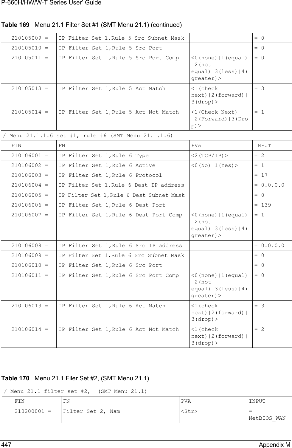
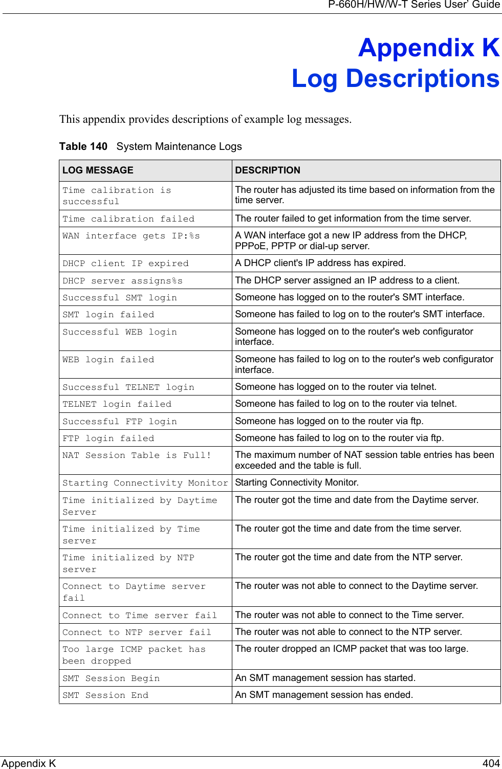
![P-660H/HW/W-T Series User’ GuideAppendix K 418Log CommandsGo to the command interpreter interface. Configuring What You Want the Prestige to Log1Use the sys logs load command to load the log setting buffer that allows you to configure which logs the Prestige is to record. 2Use sys logs category to view a list of the log categories.Figure 264 Displaying Log Categories Example3Use sys logs category followed by a log category to display the parameters that are available for the category.Figure 265 Displaying Log Parameters Example4Use sys logs category followed by a log category and a parameter to decide what to record.SIG SignatureNONCE NonceNOTFY NotificationDEL DeleteVID Vendor IDTable 159 RFC-2408 ISAKMP Payload Types (continued)LOG DISPLAY PAYLOAD TYPECopyright (c) 1994 - 2004 ZyXEL Communications Corp.ras>?Valid commands are:sys exit ether auxip ipsec bridge bmcertificates cnm 8021x radiusras>ras> sys logs category accessUsage: [0:none/1:log/2:alert/3:both] [0:don't show debug type/1:show debug type]](https://usermanual.wiki/ZyXEL-Communications/P660HWTX.Users-Manual-4/User-Guide-566053-Page-118.png)
![P-660H/HW/W-T Series User’ Guide419 Appendix KUse 0 to not record logs for that category, 1 to record only logs for that category, 2 to record only alerts for that category, and 3 to record both logs and alerts for that category. Not every parameter is available with every category.5Step 5.Use the sys logs save command to store the settings in the Prestige (you must do this in order to record logs).Displaying Logs• Use the sys logs display command to show all of the logs in the Prestige’s log.• Use the sys logs category display command to show the log settings for all of the log categories.• Use the sys logs display [log category] command to show the logs in an individual Prestige log category.• Use the sys logs clear command to erase all of the Prestige’s logs.Log Command ExampleThis example shows how to set the Prestige to record the access logs and alerts and then view the results.ras> sys logs loadras> sys logs category access 3ras> sys logs saveras> sys logs display access#.time source destination notes message 0|06/08/2004 05:58:21 |172.21.4.154 |224.0.1.24 |ACCESS BLOCK Firewall default policy: IGMP (W to W/ZW) 1|06/08/2004 05:58:20 |172.21.3.56 |239.255.255.250 |ACCESS BLOCK Firewall default policy: IGMP (W to W/ZW) 2|06/08/2004 05:58:20 |172.21.0.2 |239.255.255.254 |ACCESS BLOCK Firewall default policy: IGMP (W to W/ZW) 3|06/08/2004 05:58:20 |172.21.3.191 |224.0.1.22 |ACCESS BLOCK Firewall default policy: IGMP (W to W/ZW) 4|06/08/2004 05:58:20 |172.21.0.254 |224.0.0.1 |ACCESS BLOCK Firewall default policy: IGMP (W to W/ZW) 5|06/08/2004 05:58:20 |172.21.4.187:137 |172.21.255.255:137 |ACCESS BLOCK Firewall default policy: UDP (W to W/ZW)](https://usermanual.wiki/ZyXEL-Communications/P660HWTX.Users-Manual-4/User-Guide-566053-Page-119.png)