ZyXEL Communications P660HWTX 802.11g Wireless ADSL2+4 port Gateway User Manual 4
ZyXEL Communications Corporation 802.11g Wireless ADSL2+4 port Gateway Users Manual 4
Contents
- 1. Users Manual 1
- 2. Users Manual 2
- 3. Users Manual 3
- 4. Users Manual 4
Users Manual 4

P-660H/HW/W-T Series User’ Guide
301 Chapter 32 System Information and Diagnosis
Figure 193 Sample Error and Information Messages
32.4.2 Syslog and Accounting
The Prestige uses the syslog facility to log the CDR (Call Detail Record) and system messages
to a syslog server. Syslog and accounting can be configured in Menu 24.3.2 — System
Maintenance — UNIX Syslog, as shown next.
Figure 194 Menu 24.3.2 System Maintenance: Syslog and Accounting
You need to configure the UNIX syslog parameters described in the following table to activate
syslog then choose what you want to log.
The following are examples of the four types of syslog messages sent by the Prestige:
53 Sat Jan 01 00:00:03 2000 PP01 -WARN SNMP TRAP 0: cold start
54 Sat Jan 01 00:00:03 2000 PP01 INFO main: init completed
55 Sat Jan 01 00:00:03 2000 PP01 INFO Starting Connectivity Monitor
56 Sat Jan 01 00:00:03 2000 PP20 INFO adjtime task pause 1 day
57 Sat Jan 01 00:00:03 2000 PP21 INFO monitoring WAN connectivity
58 Sat Jan 01 00:03:06 2000 PP19 INFO SMT Password pass
59 Sat Jan 01 00:03:06 2000 PP01 INFO SMT Session Begin
60 Sat Jan 01 00:23:21 2000 PP01 INFO SMT Session End
62 Sat Jan 01 00:23:38 2000 PP19 INFO SMT Password pass
63 Sat Jan 01 00:23:38 2000 PP01 INFO SMT Session Begin
Clear Error Log (y/n):
Menu 24.3.2 - System Maintenance - UNIX Syslog
UNIX Syslog:
Active= No
Syslog IP Address= ?
Log Facility= Local 1
Press ENTER to Confirm or ESC to Cancel:
Table 107 Menu 24.3.2 System Maintenance : Syslog and Accounting
PARAMETER DESCRIPTION
UNIX Syslog:
Active Use [SPACE BAR] and then [ENTER] to turn syslog on or off.
Syslog IP Address Type the IP address of your syslog server.
Log Facility Use [SPACE BAR] and then [ENTER] to select one of seven different local
options. The log facility lets you log the message in different server files. Refer to
your UNIX manual.
When you have completed this menu, press [ENTER] at the prompt “Press ENTER to Confirm
or ESC to Cancel:” to save your configuration, or press [ESC] at any time to cancel.

P-660H/HW/W-T Series User’ Guide
Chapter 32 System Information and Diagnosis 302
Figure 195 Syslog Example
1 - CDR
SdcmdSyslogSend ( SYSLOG_CDR, SYSLOG_INFO, String);
String = board xx line xx channel xx, call xx, str
board = the hardware board ID
line = the WAN ID in a board
Channel = channel ID within the WAN
call = the call reference number which starts from 1 and increments by 1 for each new
call
str = C01 Outgoing Call dev xx ch xx (dev:device No. ch:channel No.)
C01 Incoming Call xxxxBps xxxxx (L2TP, xxxxx = Remote Call ID)
C01 Incoming Call xxxx (= connected speed) xxxxx (= Remote Call ID)
L02 Tunnel Connected (L2TP)
C02 OutCall Connected xxxx (= connected speed) xxxxx (= Remote Call ID)
C02 CLID call refused
L02 Call Terminated
C02 Call Terminated
Jul 19 11:19:27 192.168.102.2 ZYXEL: board 0 line 0 channel 0, call 1, C01 Outgoing
Call dev=2 ch=0 40002
Jul 19 11:19:32 192.168.102.2 ZYXEL: board 0 line 0 channel 0, call 1, C02 OutCall
Connected 64000 40002
Jul 19 11:20:06 192.168.102.2 ZYXEL: board 0 line 0 channel 0, call 1, C02 Call
Terminated
2 - Packet Triggered
SdcmdSyslogSend (SYSLOG_PKTTRI, SYSLOG_NOTICE, String);
String = Packet trigger: Protocol=xx Data=xxxxxxxxxx…..x
Protocol: (1:IP 2:IPX 3:IPXHC 4:BPDU 5:ATALK 6:IPNG)
Data: We will send forty-eight Hex characters to the server
Jul 19 11:28:39 192.168.102.2 ZYXEL: Packet Trigger: Protocol=1,
Data=4500003c100100001f010004c0a86614ca849a7b08004a5c020001006162636465666768696a6b6c
6d6e6f7071727374
Jul 19 11:28:56 192.168.102.2 ZYXEL: Packet Trigger: Protocol=1,
Data=4500002c1b0140001f06b50ec0a86614ca849a7b0427001700195b3e00000000600220008cd40000
020405b4
Jul 19 11:29:06 192.168.102.2 ZYXEL: Packet Trigger: Protocol=1,
Data=45000028240140001f06ac12c0a86614ca849a7b0427001700195b451d1430135004000077600000
3 - Filter Log
SdcmdSyslogSend (SYSLOG_FILLOG, SYSLOG_NOTICE, String);
String = IP[Src=xx.xx.xx.xx Dst=xx.xx.xx.xx prot spo=xxxx dpo=xxxx] S04>R01mD
IP[…] is the packet header and S04>R01mD means filter set 4 (S) and rule 1 (R), match
(m), drop (D).
Src: Source Address
Dst: Destination Address

P-660H/HW/W-T Series User’ Guide
303 Chapter 32 System Information and Diagnosis
32.5 Diagnostic
The diagnostic facility allows you to test the different aspects of your Prestige to determine if
it is working properly. Menu 24.4 allows you to choose among various types of diagnostic
tests to evaluate your system, as shown in the following figure.
Follow the procedure next to get to Diagnostic:
1From the main menu, type 24 to open Menu 24 – System Maintenance.
2From this menu, type 4. Diagnostic to open Menu 24.4 – System Maintenance –
Diagnostic.
Figure 196 Menu 24.4 System Maintenance : Diagnostic
prot: Protocol (“TCP”, ”UDP”, ”ICMP”)
spo: Source port
dpo: Destination port
Jul 19 14:43:55 192.168.102.2 ZYXEL: IP [Src=202.132.154.123 Dst=255.255.255.255 UDP
spo=0208 dpo=0208]} S03>R01mF
Jul 19 14:44:00 192.168.102.2 ZYXEL: IP [Src=192.168.102.20 Dst=202.132.154.1 UDP
spo=05d4 dpo=0035]} S03>R01mF
Jul 19 14:44:04 192.168.102.2 ZYXEL: IP [Src=192.168.102.20 Dst=202.132.154.1 UDP
spo=05d4 dpo=0035]} S03>R01mF
4 - PPP Log
SdcmdSyslogSend (SYSLOG_PPPLOG, SYSLOG_NOTICE, String);
String = ppp:Proto Starting / ppp:Proto Opening / ppp:Proto Closing / ppp:Proto
Shutdown
Proto = LCP / ATCP / BACP / BCP / CBCP / CCP / CHAP/ PAP / IPCP / IPXCP
Jul 19 11:42:44 192.168.102.2 ZYXEL: ppp:LCP Closing
Jul 19 11:42:49 192.168.102.2 ZYXEL: ppp:IPCP Closing
Jul 19 11:42:54 192.168.102.2 ZYXEL: ppp:CCP Closing
Figure 195 Syslog Example (continued)
Menu 24.4 - System Maintenance - Diagnostic
xDSL System
1. Reset xDSL 21. Reboot System
22. Command Mode
TCP/IP
12. Ping Host
Enter Menu Selection Number:
Host IP Address= N/A

P-660H/HW/W-T Series User’ Guide
Chapter 32 System Information and Diagnosis 304
The following table describes the diagnostic tests available in menu 24.4 for and the
connections.
Table 108 Menu 24.4 System Maintenance Menu: Diagnostic
FIELD DESCRIPTION
Reset xDSL Re-initialize the xDSL link to the telephone company.
Ping Host Ping the host to see if the links and TCP/IP protocol on both systems are working.
Reboot System Reboot the Prestige.
Command Mode Type the mode to test and diagnose your Prestige using specified commands.
Host IP Address If you typed 12 to Ping Host, now type the address of the computer you want to
ping.

P-660H/HW/W-T Series User’ Guide
305 Chapter 32 System Information and Diagnosis

P-660H/HW/W-T Series User’ Guide
Chapter 33 Firmware and Configuration File Maintenance 306
CHAPTER 33
Firmware and Configuration File
Maintenance
This chapter tells you how to backup and restore your configuration file as well as upload new
firmware and configuration files.
33.1 Filename Conventions
The configuration file (often called the romfile or rom-0) contains the factory default settings
in the menus such as password, DHCP Setup, TCP/IP Setup, etc. It arrives from ZyXEL with a
“rom” filename extension. Once you have customized the Prestige's settings, they can be
saved back to your computer under a filename of your choosing.
ZyNOS (ZyXEL Network Operating System sometimes referred to as the “ras” file) is the
system firmware and has a “bin” filename extension. With many FTP and TFTP clients, the
filenames are similar to those seen next.
Note: Only use firmware for your Prestige’s specific model. Refer to the label on the
bottom of your Prestige.
ftp> put firmware.bin ras
This is a sample FTP session showing the transfer of the computer file "firmware.bin" to the
Prestige.
ftp> get rom-0 config.cfg
This is a sample FTP session saving the current configuration to the computer file
“config.cfg”.
If your (T)FTP client does not allow you to have a destination filename different than the
source, you will need to rename them as the Prestige only recognizes “rom-0” and “ras”. Be
sure you keep unaltered copies of both files for later use.

P-660H/HW/W-T Series User’ Guide
307 Chapter 33 Firmware and Configuration File Maintenance
The following table is a summary. Please note that the internal filename refers to the filename
on the Prestige and the external filename refers to the filename not on the Prestige, that is, on
your computer, local network or FTP site and so the name (but not the extension) may vary.
After uploading new firmware, see the ZyNOS F/W Version field in Menu 24.2.1 – System
Maintenance – Information to confirm that you have uploaded the correct firmware version.
The AT command is the command you enter after you press “y” when prompted in the SMT
menu to go into debug mode.
33.2 Backup Configuration
Option 5 from Menu 24 – System Maintenance allows you to backup the current Prestige
configuration to your computer. Backup is highly recommended once your Prestige is
functioning properly. FTP is the preferred methods for backing up your current configuration
to your computer since they are faster. Any serial communications program should work fine;
however, you must use Xmodem protocol to perform the download/upload and you don’t have
to rename the files.
Please note that terms “download” and “upload” are relative to the computer. Download
means to transfer from the Prestige to the computer, while upload means from your computer
to the Prestige.
33.2.1 Backup Configuration
Follow the instructions as shown in the next screen.
Table 109 Filename Conventions
FILE TYPE INTERNAL NAME EXTERNAL NAME DESCRIPTION
Configuration
File
Rom-0 This is the configuration filename on the
Prestige. Uploading the rom-0 file replaces the
entire ROM file system, including your Prestige
configurations, system-related data (including
the default password), the error log and the
trace log.
*.rom
Firmware Ras This is the generic name for the ZyNOS
firmware on the Prestige.
*.bin

P-660H/HW/W-T Series User’ Guide
Chapter 33 Firmware and Configuration File Maintenance 308
Figure 197 Telnet in Menu 24.5
33.2.2 Using the FTP Command from the Command Line
1Launch the FTP client on your computer.
2Enter “open”, followed by a space and the IP address of your Prestige.
3Press [ENTER] when prompted for a username.
4Enter your password as requested (the default is “1234”).
5Enter “bin” to set transfer mode to binary.
6Use “get” to transfer files from the Prestige to the computer, for example, “get rom-0
config.rom” transfers the configuration file on the Prestige to your computer and
renames it “config.rom”. See earlier in this chapter for more information on filename
conventions.
7Enter “quit” to exit the ftp prompt.
33.2.3 Example of FTP Commands from the Command Line
Menu 24.5 - System Maintenance - Backup Configuration
To transfer the configuration file to your workstation, follow the procedure
below:
1. Launch the FTP client on your workstation.
2. Type "open" and the IP address of your Prestige. Then type "root" and SMT
password as requested.
3. Locate the 'rom-0' file.
4. Type 'get rom-0' to back up the current Prestige configuration to
your workstation.
For details on FTP commands, please consult the documentation of your FTP
client program. For details on backup using TFTP (note that you must remain
in this menu to back up using TFTP), please see your Prestige manual.
Press ENTER to Exit:

P-660H/HW/W-T Series User’ Guide
309 Chapter 33 Firmware and Configuration File Maintenance
Figure 198 FTP Session Example
33.2.4 GUI-based FTP Clients
The following table describes some of the commands that you may see in GUI-based FTP
clients.
33.2.5 TFTP and FTP over WAN Management Limitations
TFTP, FTP and Telnet over WAN will not work when:
• You have disabled Telnet service in menu 24.11.
• You have applied a filter in menu 3.1 (LAN) or in menu 11.5 (WAN) to block Telnet
service.
• The IP address in the Secured Client IP field in menu 24.11 does not match the client IP.
If it does not match, the Prestige will disconnect the Telnet session immediately.
• You have an SMT console session running.
331 Enter PASS command
Password:
230 Logged in
ftp> bin
200 Type I OK
ftp> get rom-0 zyxel.rom
200 Port command okay
150 Opening data connection for STOR ras
226 File received OK
ftp: 16384 bytes sent in 1.10Seconds 297.89Kbytes/sec.
ftp> quit
Table 110 General Commands for GUI-based FTP Clients
COMMAND DESCRIPTION
Host Address Enter the address of the host server.
Login Type Anonymous.
This is when a user I.D. and password is automatically supplied to the
server for anonymous access. Anonymous logins will work only if your ISP
or service administrator has enabled this option.
Normal.
The server requires a unique User ID and Password to login.
Transfer Type Transfer files in either ASCII (plain text format) or in binary mode.
Initial Remote Directory Specify the default remote directory (path).
Initial Local Directory Specify the default local directory (path).

P-660H/HW/W-T Series User’ Guide
Chapter 33 Firmware and Configuration File Maintenance 310
33.2.6 Backup Configuration Using TFTP
The Prestige supports the up/downloading of the firmware and the configuration file using
TFTP (Trivial File Transfer Protocol) over LAN. Although TFTP should work over WAN as
well, it is not recommended.
To use TFTP, your computer must have both telnet and TFTP clients. To backup the
configuration file, follow the procedure shown next.
1Use telnet from your computer to connect to the Prestige and log in. Because TFTP does
not have any security checks, the Prestige records the IP address of the telnet client and
accepts TFTP requests only from this address.
2Put the SMT in command interpreter (CI) mode by entering 8 in Menu 24 – System
Maintenance.
3Enter command “sys stdio 0” to disable the SMT timeout, so the TFTP transfer will
not be interrupted. Enter command “sys stdio 5” to restore the five-minute SMT
timeout (default) when the file transfer is complete.
4Launch the TFTP client on your computer and connect to the Prestige. Set the transfer
mode to binary before starting data transfer.
5Use the TFTP client (see the example below) to transfer files between the Prestige and the
computer. The file name for the configuration file is “rom-0” (rom-zero, not capital o).
Note that the telnet connection must be active and the SMT in CI mode before and during the
TFTP transfer. For details on TFTP commands (see following example), please consult the
documentation of your TFTP client program. For UNIX, use “get” to transfer from the
Prestige to the computer and “binary” to set binary transfer mode.
33.2.7 TFTP Command Example
The following is an example TFTP command:
tftp [-i] host get rom-0 config.rom
where “i” specifies binary image transfer mode (use this mode when transferring binary files),
“host” is the Prestige IP address, “get” transfers the file source on the Prestige (rom-0,
name of the configuration file on the Prestige) to the file destination on the computer and
renames it config.rom.
33.2.8 GUI-based TFTP Clients
The following table describes some of the fields that you may see in GUI-based TFTP clients.

P-660H/HW/W-T Series User’ Guide
311 Chapter 33 Firmware and Configuration File Maintenance
Refer to Section 33.2.5 on page 309 to read about configurations that disallow TFTP and FTP
over WAN.
33.3 Restore Configuration
This section shows you how to restore a previously saved configuration. Note that this
function erases the current configuration before restoring a previous back up configuration;
please do not attempt to restore unless you have a backup configuration file stored on disk.
FTP is the preferred method for restoring your current computer configuration to your Prestige
since FTP is faster. Please note that you must wait for the system to automatically restart after
the file transfer is complete.
Note: Do not interrupt the file transfer process as this may PERMANENTLY
DAMAGE YOUR Prestige.
33.3.1 Restore Using FTP
For details about backup using (T)FTP please refer to earlier sections on FTP and TFTP file
upload in this chapter.
Table 111 General Commands for GUI-based TFTP Clients
COMMAND DESCRIPTION
Host Enter the IP address of the Prestige. 192.168.1.1 is the Prestige’s default IP address
when shipped.
Send/Fetch Use “Send” to upload the file to the Prestige and “Fetch” to back up the file on your
computer.
Local File Enter the path and name of the firmware file (*.bin extension) or configuration file (*.rom
extension) on your computer.
Remote File This is the filename on the Prestige. The filename for the firmware is “ras” and for the
configuration file, is “rom-0”.
Binary Transfer the file in binary mode.
Abort Stop transfer of the file.

P-660H/HW/W-T Series User’ Guide
Chapter 33 Firmware and Configuration File Maintenance 312
Figure 199 Telnet into Menu 24.6
1Launch the FTP client on your computer.
2Enter “open”, followed by a space and the IP address of your Prestige.
3Press [ENTER] when prompted for a username.
4Enter your password as requested (the default is “1234”).
5Enter “bin” to set transfer mode to binary.
6Find the “rom” file (on your computer) that you want to restore to your Prestige.
7Use “put” to transfer files from the Prestige to the computer, for example, “put
config.rom rom-0” transfers the configuration file “config.rom” on your computer
to the Prestige. See earlier in this chapter for more information on filename conventions.
8Enter “quit” to exit the ftp prompt. The Prestige will automatically restart after a
successful restore process.
33.3.2 Restore Using FTP Session Example
Figure 200 Restore Using FTP Session Example
Refer to Section 33.2.5 on page 309 to read about configurations that disallow TFTP and FTP
over WAN.
Menu 24.6 -- System Maintenance - Restore Configuration
To transfer the firmware and configuration file to your workstation, follow
the procedure below:
1. Launch the FTP client on your workstation.
2. Type "open" and the IP address of your Prestige. Then type "root" and SMT
password as requested.
3. Type "put backupfilename rom-0" where backupfilename is the name of
your backup configuration file on your workstation and rom-0 is the
remote file name on the Prestige. This restores the configuration to
your Prestige.
4. The system reboots automatically after a successful file transfer
For details on FTP commands, please consult the documentation of your FTP
client program. For details on backup using TFTP (note that you must remain
in this menu to back up using TFTP), please see your Prestige manual.
Press ENTER to Exit:
ftp> put config.rom rom-0
200 Port command okay
150 Opening data connection for STOR rom-0
226 File received OK
221 Goodbye for writing flash
ftp: 16384 bytes sent in 0.06Seconds 273.07Kbytes/sec.
ftp>quit

P-660H/HW/W-T Series User’ Guide
313 Chapter 33 Firmware and Configuration File Maintenance
33.4 Uploading Firmware and Configuration Files
This section shows you how to upload firmware and configuration files. You can upload
configuration files by following the procedure in Section 33.2 on page 307 or by following the
instructions in Menu 24.7.2 – System Maintenance – Upload System Configuration File.
Note: Do not interrupt the file transfer process as this may PERMANENTLY
DAMAGE YOUR Prestige.
33.4.1 Firmware File Upload
FTP is the preferred method for uploading the firmware and configuration. To use this feature,
your computer must have an FTP client.
When you telnet into the Prestige, you will see the following screens for uploading firmware
and the configuration file using FTP.
Figure 201 Telnet Into Menu 24.7.1 Upload System Firmware
33.4.2 Configuration File Upload
You see the following screen when you telnet into menu 24.7.2.
Menu 24.7.1 - System Maintenance - Upload System Firmware
To upload the system firmware, follow the procedure below:
1. Launch the FTP client on your workstation.
2. Type "open" and the IP address of your system. Then type "root" and
SMT password as requested.
3. Type "put firmware filename ras" where "firmwarefilename" is the name
of your firmware upgrade file on your workstation and "ras" is the
remote file name on the system.
4. The system reboots automatically after a successful firmware upload.
For details on FTP commands, please consult the documentation of your FTP
client program. For details on uploading system firmware using TFTP (note
that you must remain on this menu to upload system firmware using TFTP),
please see your manual.
Press ENTER to Exit:

P-660H/HW/W-T Series User’ Guide
Chapter 33 Firmware and Configuration File Maintenance 314
Figure 202 Telnet Into Menu 24.7.2 System Maintenance
To upload the firmware and the configuration file, follow these examples
33.4.3 FTP File Upload Command from the DOS Prompt Example
1Launch the FTP client on your computer.
2Enter “open”, followed by a space and the IP address of your Prestige.
3Press [ENTER] when prompted for a username.
4Enter your password as requested (the default is “1234”).
5Enter “bin” to set transfer mode to binary.
6Use “put” to transfer files from the computer to the Prestige, for example, “put
firmware.bin ras” transfers the firmware on your computer (firmware.bin) to the
Prestige and renames it “ras”. Similarly, “put config.rom rom-0” transfers the
configuration file on your computer (config.rom) to the Prestige and renames it “rom-0”.
Likewise “get rom-0 config.rom” transfers the configuration file on the Prestige to
your computer and renames it “config.rom.” See earlier in this chapter for more
information on filename conventions.
7Enter “quit” to exit the ftp prompt.
The Prestige automatically restarts after a successful file upload.
Menu 24.7.2 - System Maintenance - Upload System Configuration File
To upload the system configuration file, follow the procedure below:
1. Launch the FTP client on your workstation.
2. Type "open" and the IP address of your system. Then type "root" and
SMT password as requested.
3. Type "put configuration filename rom-0" where "configurationfilename"
is the name of your system configuration file on your workstation, which
will be transferred to the "rom-0" file on the system.
4. The system reboots automatically after the upload system configuration
file process is complete.
For details on FTP commands, please consult the documentation of your FTP
client program. For details on uploading system firmware using TFTP (note
that you must remain on this menu to upload system firmware using TFTP),
please see your manual.
Press ENTER to Exit:

P-660H/HW/W-T Series User’ Guide
315 Chapter 33 Firmware and Configuration File Maintenance
33.4.4 FTP Session Example of Firmware File Upload
Figure 203 FTP Session Example of Firmware File Upload
More commands (found in GUI-based FTP clients) are listed earlier in this chapter.
Refer to Section 33.2.5 on page 309 to read about configurations that disallow TFTP and FTP
over WAN.
33.4.5 TFTP File Upload
The Prestige also supports the uploading of firmware files using TFTP (Trivial File Transfer
Protocol) over LAN. Although TFTP should work over WAN as well, it is not recommended.
To use TFTP, your computer must have both telnet and TFTP clients. To transfer the firmware
and the configuration file, follow the procedure shown next.
1Use telnet from your computer to connect to the Prestige and log in. Because TFTP does
not have any security checks, the Prestige records the IP address of the telnet client and
accepts TFTP requests only from this address.
2Put the SMT in command interpreter (CI) mode by entering 8 in Menu 24 – System
Maintenance.
3Enter the command “sys stdio 0” to disable the console timeout, so the TFTP transfer
will not be interrupted. Enter “sys stdio 5” to restore the five-minute console timeout
(default) when the file transfer is complete.
4Launch the TFTP client on your computer and connect to the Prestige. Set the transfer
mode to binary before starting data transfer.
5Use the TFTP client (see the example below) to transfer files between the Prestige and the
computer. The file name for the firmware is “ras”.
Note that the telnet connection must be active and the Prestige in CI mode before and during
the TFTP transfer. For details on TFTP commands (see following example), please consult the
documentation of your TFTP client program. For UNIX, use “get” to transfer from the
Prestige to the computer, “put” the other way around, and “binary” to set binary transfer
mode.
331 Enter PASS command
Password:
230 Logged in
ftp> bin
200 Type I OK
ftp> put firmware.bin ras
200 Port command okay
150 Opening data connection for STOR ras
226 File received OK
ftp: 1103936 bytes sent in 1.10Seconds 297.89Kbytes/sec.
ftp> quit

P-660H/HW/W-T Series User’ Guide
Chapter 33 Firmware and Configuration File Maintenance 316
33.4.6 TFTP Upload Command Example
The following is an example TFTP command:
tftp [-i] host put firmware.bin ras
where “i” specifies binary image transfer mode (use this mode when transferring binary files),
“host” is the Prestige’s IP address and “put” transfers the file source on the computer
(firmware.bin – name of the firmware on the computer) to the file destination on the
remote host (ras - name of the firmware on the Prestige).
Commands that you may see in GUI-based TFTP clients are listed earlier in this chapter.

P-660H/HW/W-T Series User’ Guide
317 Chapter 33 Firmware and Configuration File Maintenance

P-660H/HW/W-T Series User’ Guide
Chapter 34 System Maintenance 318
CHAPTER 34
System Maintenance
This chapter leads you through SMT menus 24.8 to 24.10.
34.1 Command Interpreter Mode
The Command Interpreter (CI) is a part of the main system firmware. The CI provides much of
the same functionality as the SMT, while adding some low-level setup and diagnostic
functions. Enter the CI from the SMT by selecting menu 24.8. See the included disk or the
zyxel.com web site for more detailed information on CI commands. Enter 8 from Menu 24 —
System Maintenance. A list of valid commands can be found by typing help or ? at the
command prompt. Type “exit” to return to the SMT main menu when finished.
Figure 204 Command Mode in Menu 24
Figure 205 Valid Commands
Menu 24 - System Maintenance
1. System Status
2. System Information and Console Port Speed
3. Log and Trace
4. Diagnostic
5. Backup Configuration
6. Restore Configuration
7. Upload Firmware
8. Command Interpreter Mode
9. Call Control
10. Time and Date Setting
11. Remote Management
Enter Menu Selection Number:
Copyright (c) 1994 - 2004 ZyXEL Communications Corp.
ras> ?
Valid commands are:
sys exit device ether
wan poe config pci
wlan ip ppp bridge
hdap bm lan radius
8021x
ras>

P-660H/HW/W-T Series User’ Guide
319 Chapter 34 System Maintenance
34.2 Call Control Support
Call Control Support is only applicable when Encapsulation is set to PPPoE in menu 4 or
menu 11.1.
The budget management function allows you to set a limit on the total outgoing call time of
the Prestige within certain times. When the total outgoing call time exceeds the limit, the
current call will be dropped and any future outgoing calls will be blocked.
To access the call control menu, select option 9 in menu 24 to go to Menu 24.9 — System
Maintenance — Call Control, as shown in the next table.
Figure 206 Menu 24.9 System Maintenance: Call Control
34.2.1 Budget Management
Menu 24.9.1 shows the budget management statistics for outgoing calls. Enter 1 from Menu
24.9 — System Maintenance — Call Control to bring up the following menu.
Menu 24.9 - System Maintenance - Call Control
1. Budget Management
Enter Menu Selection Number:

P-660H/HW/W-T Series User’ Guide
Chapter 34 System Maintenance 320
Figure 207 Menu 24.9.1 System Maintenance: Budget Management
The total budget is the time limit on the accumulated time for outgoing calls to a remote node.
When this limit is reached, the call will be dropped and further outgoing calls to that remote
node will be blocked. After each period, the total budget is reset. The default for the total
budget is 0 minutes and the period is 0 hours, meaning no budget control. You can reset the
accumulated connection time in this menu by entering the index of a remote node. Enter 0 to
update the screen. The budget and the reset period can be configured in menu 11.1 for the
remote node when PPPoE encapsulation is selected.
34.3 Time and Date Setting
The Prestige keeps track of the time and date. There is also a software mechanism to set the
time manually or get the current time and date from an external server when you turn on your
Prestige. Menu 24.10 allows you to update the time and date settings of your Prestige. The real
time is then displayed in the Prestige error logs and firewall logs.
Select menu 24 in the main menu to open Menu 24 System Maintenance, as shown next.
Menu 24.9.1 - System Maintenance - Budget Management
Remote Node
1.MyIsp
2.--------
3.--------
4.--------
5.--------
6.--------
7.--------
8.--------
Connection Time/Total Budget
No Budget
---
---
---
---
---
---
---
Elapsed Time/Total Period
No Budget
---
---
---
---
---
---
---
Reset Node (0 to update screen):
Table 112 Menu 24.9.1 System Maintenance: Budget Management
FIELD DESCRIPTION
Remote Node Enter the index number of the remote node you want to reset (just one in
this case)
Connection Time/Total
Budget
This is the total connection time that has gone by (within the allocated
budget that you set in menu 11.1.
Elapsed Time/Total Period The period is the time cycle in hours that the allocation budget is reset
(see menu 11.1.) The elapsed time is the time used up within this period.
Enter “0” to update the screen or press [ESC] to return to the previous screen.

P-660H/HW/W-T Series User’ Guide
321 Chapter 34 System Maintenance
Figure 208 Menu 24 System Maintenance
Then enter 10 to go to Menu 24.10 System Maintenance Time and Date Setting to update
the time and date settings of your Prestige as shown in the following screen.
Figure 209 Menu 24.10 System Maintenance: Time and Date Setting
Menu 24 - System Maintenance
1. System Status
2. System Information and Console Port Speed
3. Log and Trace
4. Diagnostic
5. Backup Configuration
6. Restore Configuration
7. Upload Firmware
8. Command Interpreter Mode
9. Call Control
10. Time and Date Setting
11. Remote Management
Enter Menu Selection Number:
Menu 24.10 - System Maintenance - Time and Date Setting
Use Time Server when Bootup= None
Time Server Address= N/A
Current Time: 00 : 51 : 24
New Time (hh:mm:ss): 00 : 51 : 19
Current Date: 2000 - 01 - 01
New Date (yyyy-mm-dd): 2000 - 01 - 01
Time Zone= GMT
Daylight Saving= No
Start Date (mm-dd): 01 - 00
End Date (mm-dd): 01 - 00
Press ENTER to Confirm or ESC to Cancel:
Table 113 Menu 24.10 System Maintenance: Time and Date Setting
FIELD DESCRIPTION
Use Time Server
when Bootup
Enter the time service protocol that your time server sends when you turn on
the Prestige. Not all time servers support all protocols, so you may have to
check with your ISP/network administrator or use trial and error to find a
protocol that works. The main differences between them are the format.
Daytime (RFC 867) format is day/month/year/time zone of the server.
Time (RFC-868) format displays a 4-byte integer giving the total number of
seconds since 1970/1/1 at 0:0:0.
NTP (RFC-1305) is similar to Time (RFC-868).
None. The default, enter the time manually.
Time Server Address Enter the IP address or domain name of your time server. Check with your ISP/
network administrator if you are unsure of this information.

P-660H/HW/W-T Series User’ Guide
Chapter 34 System Maintenance 322
34.3.1 Resetting the Time
• The Prestige resets the time in three instances:
• On leaving menu 24.10 after making changes.
• When the Prestige starts up, if there is a timeserver configured in menu 24.10.
• 24-hour intervals after starting.
Current Time This field displays an updated time only when you reenter this menu.
New Time Enter the new time in hour, minute and second format.
Current Date This field displays an updated date only when you re-enter this menu.
New Date Enter the new date in year, month and day format.
Time Zone Press [SPACE BAR] and then [ENTER] to set the time difference between your
time zone and Greenwich Mean Time (GMT).
Daylight Saving If you use daylight savings time, then choose Yes.
Start Date If using daylight savings time, enter the month and day that it starts on.
End Date If using daylight savings time, enter the month and day that it ends on
When you have completed this menu, press [ENTER] at the prompt “Press ENTER to Confirm
or ESC to Cancel:” to save your configuration, or press [ESC] at any time to cancel.
Table 113 Menu 24.10 System Maintenance: Time and Date Setting (continued)
FIELD DESCRIPTION

P-660H/HW/W-T Series User’ Guide
323 Chapter 34 System Maintenance

P-660H/HW/W-T Series User’ Guide
Chapter 35 Remote Management 324
CHAPTER 35
Remote Management
This chapter covers remote management (SMT menu 24.11).
35.1 Remote Management Overview
Remote management allows you to determine which services/protocols can access which
Prestige interface (if any) from which computers.
When you configure remote management to allow management from the WAN, you still need
to configure a firewall rule to allow access. See the firewall chapters for details on configuring
firewall rules.
35.2 Remote Management
To disable remote management of a service, select Disable in the corresponding Server
Access field.
Enter 11 from menu 24 to display Menu 24.11 — Remote Management Control.
35.2.1 Remote Management Setup
You may manage your Prestige from a remote location via:
the Internet (WAN only), the LAN only, All (LAN and WAN) or Disable (neither).
• WAN only (Internet)
• ALL (LAN and WAN)
• LAN only
• Disable (Neither)
If you enable remote management of a service, but have applied a filter to block the service,
then you will not be able to remotely manage the Prestige using the service.
Enter 11, from menu 24, to display Menu 24.11 — Remote Management Control (shown
next).

P-660H/HW/W-T Series User’ Guide
325 Chapter 35 Remote Management
Figure 210 Menu 24.11 Remote Management Control
The following table describes the fields in this menu.
35.2.2 Remote Management Limitations
Remote management over LAN or WAN will not work when:
• A filter in menu 3.1 (LAN) or in menu 11.5 (WAN) is applied to block a Telnet, FTP or
Web service.
• You have disabled that service in menu 24.11.
• The IP address in the Secured Client IP field (menu 24.11) does not match the client IP
address. If it does not match, the Prestige will disconnect the session immediately.
• There is already another remote management session with an equal or higher priority
running. You may only have one remote management session running at one time.
• There is a firewall rule that blocks it.
Menu 24.11 - Remote Management Control
TELNET Server:
Server Port = 23 Server Access = LAN only
Secured Client IP = 0.0.0.0
FTP Server:
Server Port = 21 Server Access = LAN only
Secured Client IP = 0.0.0.0
Web Server:
Server Port = 80 Server Access = LAN only
Secured Client IP = 0.0.0.0
Press ENTER to Confirm or ESC to Cancel:
Table 114 Menu 24.11 Remote Management Control
FIELD DESCRIPTION
Telnet Server
FTP Server
Web Server
Each of these read-only labels denotes a service or protocol.
Port This field shows the port number for the service or protocol. You may change the
port number if needed, but you must use the same port number to access the
Prestige.
Access Select the access interface (if any) by pressing the [SPACE BAR]. Choices are:
LAN only, WAN only, All or Disable. The default is LAN only.
Secured Client IP The default 0.0.0.0 allows any client to use this service or protocol to access the
Prestige. Enter an IP address to restrict access to a client with a matching IP
address.
When you have completed this menu, press [ENTER] at the prompt “Press ENTER to Confirm
or ESC to Cancel:” to save your configuration, or press [ESC] at any time to cancel.

P-660H/HW/W-T Series User’ Guide
Chapter 35 Remote Management 326
35.3 Remote Management and NAT
When NAT is enabled:
• Use the Prestige’s WAN IP address when configuring from the WAN.
• Use the Prestige’s LAN IP address when configuring from the LAN.
35.4 System Timeout
There is a default system management idle timeout of five minutes (three hundred seconds).
The Prestige automatically logs you out if the management session remains idle for longer
than this timeout period. The management session does not time out when it is continuously
updating the status in menu 24.1 or when sys stdio has been changed on the command
line.

P-660H/HW/W-T Series User’ Guide
327 Chapter 35 Remote Management

P-660H/HW/W-T Series User’ Guide
Chapter 36 IP Policy Routing 328
CHAPTER 36
IP Policy Routing
This chapter covers setting and applying policies used for IP routing.
36.1 IP Policy Routing Overview
Traditionally, routing is based on the destination address only and the IAD takes the shortest
path to forward a packet. IP Routing Policy (IPPR) provides a mechanism to override the
default routing behavior and alter the packet forwarding based on the policy defined by the
network administrator. Policy-based routing is applied to incoming packets on a per interface
basis, prior to the normal routing.
36.2 Benefits of IP Policy Routing
Source-Based Routing – Network administrators can use policy-based routing to direct traffic
from different users through different connections.
Quality of Service (QoS) – Organizations can differentiate traffic by setting the precedence or
TOS (Type of Service) values in the IP header at the periphery of the network to enable the
backbone to prioritize traffic.
Cost Savings – IPPR allows organizations to distribute interactive traffic on high-bandwidth,
high-cost paths while using low-cost paths for batch traffic.
Load Sharing – Network administrators can use IPPR to distribute traffic among multiple
paths.
36.3 Routing Policy
Individual routing policies are used as part of the overall IPPR process. A policy defines the
matching criteria and the action to take when a packet meets the criteria. The action is taken
only when all the criteria are met. The criteria includes the source address and port, IP protocol
(ICMP, UDP, TCP, etc.), destination address and port, TOS and precedence (fields in the IP
header) and length. The inclusion of length criterion is to differentiate between interactive and
bulk traffic. Interactive applications, for example, telnet, tend to have short packets, while bulk
traffic, for example, file transfer, tends to have large packets.
The actions that can be taken include:

P-660H/HW/W-T Series User’ Guide
329 Chapter 36 IP Policy Routing
• routing the packet to a different gateway (and hence the outgoing interface).
• setting the TOS and precedence fields in the IP header.
IPPR follows the existing packet filtering facility of RAS in style and in implementation. The
policies are divided into sets, where related policies are grouped together. A user defines the
policies before applying them to an interface or a remote node, in the same fashion as the
filters. There are 12 policy sets with six policies in each set.
36.4 IP Routing Policy Setup
Menu 25 shows all the policies defined.
Figure 211 Menu 25 IP Routing Policy Setup
To setup a routing policy, perform the following procedures:
1Type 25 in the main menu to open Menu 25 – IP Routing Policy Setup.
2Type the index of the policy set you want to configure to open Menu 25.1 – IP Routing
Policy Setup.
Menu 25.1 shows the summary of a policy set, including the criteria and the action of a single
policy, and whether a policy is active or not. Each policy contains two lines. The former part is
the criteria of the incoming packet and the latter is the action. Between these two parts,
separator “|” means the action is taken on criteria matched and separator “=” means the action
is taken on criteria not matched.
Menu 25 - IP Routing Policy Setup
Policy
Set # Name Set # Name
------ ----------------- ------ -----------------
1 _______________ 7 _______________
2 _______________ 8 _______________
3 _______________ 9 _______________
4 _______________ 10 _______________
5 _______________ 11 _______________
6 _______________ 12 _______________
Enter Policy Set Number to Configure= 0
Edit Name= N/A
Press ENTER to Confirm or ESC to Cancel:

P-660H/HW/W-T Series User’ Guide
Chapter 36 IP Policy Routing 330
Figure 212 Menu 25.1 IP Routing Policy Setup
Type a number from 1 to 6 to display Menu 25.1.1 – IP Routing Policy (see the next figure).
This menu allows you to configure a policy rule.
Menu 25.1 - IP Routing Policy Setup
# A Criteria/Action
- - ----------------------------------------------------------------------
1 Y SA=1.1.1.1-1.1.1.1,DA=2.2.2.2-2.2.2.5
SP=20-25,DP=20-25,P=6,T=NM,PR=0 |GW=192.168.1.1,T=MT,PR=0
2 N ______________________________________________________________________
______________________________________________________________________
3 N ______________________________________________________________________
______________________________________________________________________
4 N ______________________________________________________________________
______________________________________________________________________
5 N ______________________________________________________________________
______________________________________________________________________
6 N ______________________________________________________________________
______________________________________________________________________
Enter Policy Rule Number (1-6) to Configure:
Table 115 Menu 25.1 IP Routing Policy Setup
ABBREVIATION MEANING
Criterion SA Source IP Address
SP Source Port
DA Destination IP Address
DP Destination Port
P IP layer 4 protocol number (TCP=6, UDP=17…)
T Type of service of incoming packet
PR Precedence of incoming packet
Action GW Gateway IP address
T Outgoing Type of service
P Outgoing Precedence
Service NM Normal
MD Minimum Delay
MT Maximum Throughput
MR Maximum Reliability
MC Minimum Cost

P-660H/HW/W-T Series User’ Guide
331 Chapter 36 IP Policy Routing
Figure 213 Menu 25.1.1 IP Routing Policy
The following table describes the fields in this menu.
Menu 25.1.1 - IP Routing Policy
Policy Set Name= test
Active= No
Criteria:
IP Protocol = 0
Type of Service= Don't Care Packet length= 0
Precedence = Don't Care Len Comp= N/A
Source:
addr start= 0.0.0.0 end= N/A
port start= N/A end= N/A
Destination:
addr start= 0.0.0.0 end= N/A
port start= N/A end= N/A
Action= Matched
Gateway addr = 0.0.0.0 Log= No
Type of Service= No Change
Precedence = No Change
Press ENTER to Confirm or ESC to Cancel:
Table 116 Menu 25.1.1 IP Routing Policy
FIELD DESCRIPTION
Policy Set Name This is the policy set name assigned in Menu 25 – IP Routing Policy Setup.
Active Press [SPACE BAR] and then [ENTER] to select Yes to activate or No to
deactivate the policy. Inactive policies are displayed with a minus sign “-“ in SMT
menu 25.
Criteria
IP Protocol IP layer 4 protocol, for example, UDP, TCP, ICMP, etc.
Type of Service Prioritize incoming network traffic by choosing from Don’t Care, Normal, Min
Delay, Max Thruput, Min Cost or Max Reliable.
Precedence Precedence value of the incoming packet. Press [SPACE BAR] and then
[ENTER] to select a value from 0 to 7 or Don’t Care.
Packet Length Type the length of incoming packets (in bytes). The operators in the Len Comp
(next field) apply to packets of this length.
Len Comp Press [SPACE BAR] and then [ENTER] to choose from Equal, Not Equal,
Less, Greater, Less or Equal or Greater or Equal.
Source:
addr start / end Source IP address range from start to end.
port start / end Source port number range from start to end; applicable only for TCP/UDP.
Destination:
addr start / end Destination IP address range from start to end.
port start / end Destination port number range from start to end; applicable only for TCP/UDP.
Action Specifies whether action should be taken on criteria Matched or Not Matched.

P-660H/HW/W-T Series User’ Guide
Chapter 36 IP Policy Routing 332
36.5 Applying an IP Policy
This section shows you where to apply the IP policies after you design them.
36.5.1 Ethernet IP Policies
From Menu 3 — Ethernet Setup, type 2 to go to Menu 3.2 — TCP/IP and DHCP Ethernet
Setup.
You can choose up to four IP policy sets (from 12) by typing their numbers separated by
commas, for example, 2, 4, 7, 9.
Gateway addr Defines the outgoing gateway address. The gateway must be on the same
subnet as the Prestige if it is on the LAN, otherwise, the gateway must be the IP
address of a remote node. The default gateway is specified as 0.0.0.0.
Type of Service Set the new TOS value of the outgoing packet. Prioritize incoming network traffic
by choosing No Change, Normal, Min Delay, Max Thruput, Max Reliable or
Min Cost.
Precedence Set the new outgoing packet precedence value. Values are 0 to 7 or No
Change.
Log Press [SPACE BAR] and then [ENTER] to select Yes to make an entry in the
system log when a policy is executed.
When you have completed this menu, press [ENTER] at the prompt “Press ENTER to Confirm
or ESC to Cancel:” to save your configuration, or press [ESC] at any time to cancel.
Table 116 Menu 25.1.1 IP Routing Policy (continued)
FIELD DESCRIPTION

P-660H/HW/W-T Series User’ Guide
333 Chapter 36 IP Policy Routing
Figure 214 Menu 3.2 TCP/IP and DHCP Ethernet Setup
Go to menu 11.3 (shown next) and type the number(s) of the IP Routing Policy set(s) as
appropriate. You can cascade up to four policy sets by typing their numbers separated by
commas.
Figure 215 Menu 11.3 Remote Node Network Layer Options
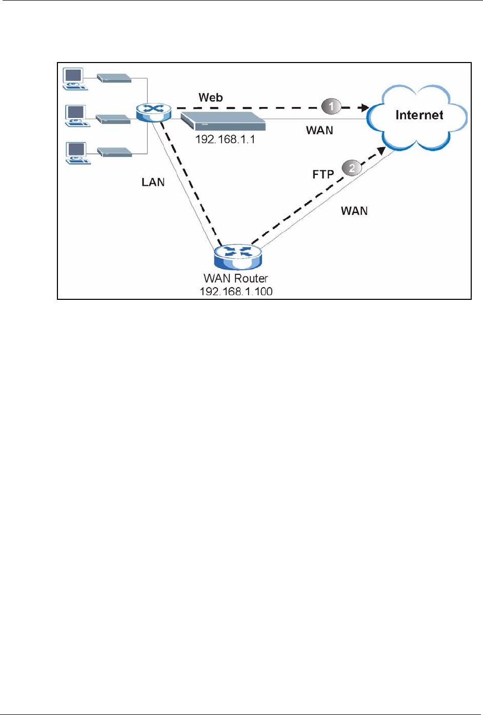
36.6 IP Policy Routing Example
If a network has both Internet and remote node connections, you can route Web packets to the
Internet using one policy and route FTP packets to a remote network using another policy. See
the next figure.
Menu 3.2 - TCP/IP and DHCP Setup
DHCP Setup
DHCP= Server
Client IP Pool Starting Address= 192.168.1.33
Size of Client IP Pool= 32
Primary DNS Server= 0.0.0.0
Secondary DNS Server= 0.0.0.0
Remote DHCP Server= N/A
TCP/IP Setup:
IP Address= 192.168.1.1
IP Subnet Mask= 255.255.255.0
RIP Direction= Both
Version= RIP-1
Multicast= None
IP Policies=
Edit IP Alias= No
Press ENTER to Confirm or ESC to Cancel:
Menu 11.3 - Remote Node Network Layer Options
IP Options: Bridge Options:
IP Address Assignment= Static Ethernet Addr Timeout (min)= 0
Rem IP Addr: 0.0.0.0
Rem Subnet Mask= 0.0.0.0
My WAN Addr= 0.0.0.0
NAT= Full Feature
Address Mapping Set= 2
Metric= 2
Private= No
RIP Direction= Both
Version= RIP-2B
Multicast= IGMP-v2
IP Policies=
Press ENTER to Confirm or ESC to Cancel:
P-660H/HW/W-T Series User’ Guide
Chapter 36 IP Policy Routing 334
Route 1 represents the default IP route and route 2 represents the configured IP route.
Figure 216 Example of IP Policy Routing
To force packets coming from clients with IP addresses of 192.168.1.33 to 192.168.1.64 to be
routed to the Internet via the WAN port of the Prestige, follow the steps as shown next.
1Create a routing policy set in menu 25.
2Create a rule for this set in Menu 25.1.1 — IP Routing Policy as shown next.

P-660H/HW/W-T Series User’ Guide
335 Chapter 36 IP Policy Routing
Figure 217 IP Routing Policy Example
1Check Menu 25.1 — IP Routing Policy Setup to see if the rule is added correctly.
2Create another policy set in menu 25.
3Create a rule in menu 25.1 for this set to route packets from any host (IP=0.0.0.0
means any host) with protocol TCP and port FTP access through another gateway
(192.168.1.100).
Menu 25.1.1 - IP Routing Policy
Policy Set Name= set1
Active= Yes
Criteria:
IP Protocol = 6
Type of Service= Don't Care
Precedence = Don't Care
Source:
addr start= 192.168.1.2
port start= 0
Destination:
addr start= 0.0.0.0
port start= 80
Action= Matched
Gateway addr = 192.168.1.1
Type of Service= No Change
Precedence = No Change
Packet length= 10
Len Comp= N/A
end= 192.168.1.64
end= N/A
end= N/A
end= 80
Log= No
Press ENTER to Confirm or ESC to Cancel:

P-660H/HW/W-T Series User’ Guide
Chapter 36 IP Policy Routing 336
Figure 218 IP Routing Policy Example
4Check Menu 25.1 — IP Routing Policy Setup to see if the rule is added correctly.
5Apply both policy sets in menu 3.2 as shown next.
Figure 219 Applying IP Policies Example
Menu 25.1.1 - IP Routing Policy
Policy Set Name= set2
Active= Yes
Criteria:
IP Protocol = 6
Type of Service= Don't Care
Precedence = Don't Care
Source:
addr start= 0.0.0.0
port start= 0
Destination:
addr start= 0.0.0.0
port start= 20
Action= Matched
Gateway addr =192.168.1.100
Type of Service= No Change
Precedence = No Change
Packet length= 10
Len Comp= N/A
end= N/A
end= N/A
end= N/A
end= 21
Log= No
Press ENTER to Confirm or ESC to Cancel:
Menu 3.2 - TCP/IP and DHCP Ethernet Setup
DHCP Setup
DHCP= Server
Client IP Pool Starting Address= 192.168.1.33
Size of Client IP Pool= 64
Primary DNS Server= 0.0.0.0
Secondary DNS Server= 0.0.0.0
Remote DHCP Server= N/A
TCP/IP Setup:
IP Address= 192.168.1.1
IP Subnet Mask= 255.255.255.0
RIP Direction= Both
Version= RIP-1
Multicast= None
IP Policies= 1,2
Edit IP Alias= No
Press ENTER to Confirm or ESC to Cancel:

P-660H/HW/W-T Series User’ Guide
337 Chapter 36 IP Policy Routing

P-660H/HW/W-T Series User’ Guide
Chapter 37 Call Scheduling 338
CHAPTER 37
Call Scheduling
Call scheduling (applicable for PPPoA or PPPoE encapsulation only) allows you to dictate
when a remote node should be called and for how long.
37.1 Introduction
The call scheduling feature allows the Prestige to manage a remote node and dictate when a
remote node should be called and for how long. This feature is similar to the scheduler in a
videocassette recorder (you can specify a time period for the VCR to record). You can apply
up to 4 schedule sets in Menu 11.1 — Remote Node Profile. From the main menu, enter 26
to access Menu 26 — Schedule Setup as shown next.
Figure 220 Menu 26 Schedule Setup
Lower numbered sets take precedence over higher numbered sets thereby avoiding scheduling
conflicts. For example, if sets 1, 2 ,3 and 4 in are applied in the remote node then set 1 will
take precedence over set 2, 3 and 4 as the Prestige, by default, applies the lowest numbered set
first. Set 2 will take precedence over set 3 and 4, and so on.
You can design up to 12 schedule sets but you can only apply up to four schedule sets for a
remote node.
To delete a schedule set, enter the set number and press [SPACE BAR] and then [ENTER]
(or delete) in the Edit Name field.
Menu 26 - Schedule Setup
Schedule
Set # Name Set # Name
------ ----------------- ------ -----------------
1 _______________ 7 _______________
2 _______________ 8 _______________
3 _______________ 9 _______________
4 _______________ 10 _______________
5 _______________ 11 _______________
6 _______________ 12 _______________
Enter Schedule Set Number to Configure= 0
Edit Name= N/A
Press ENTER to Confirm or ESC to Cancel:

P-660H/HW/W-T Series User’ Guide
339 Chapter 37 Call Scheduling
To setup a schedule set, select the schedule set you want to setup from menu 26 (1-12) and
press [ENTER] to see Menu 26.1 — Schedule Set Setup as shown next.
Figure 221 Menu 26.1 Schedule Set Setup
If a connection has been already established, your Prestige will not drop it. Once the
connection is dropped manually or it times out, then that remote node can't be triggered up
until the end of the Duration.
Menu 26.1 Schedule Set Setup
Active= Yes
Start Date(yyyy-mm-dd)= 2000 - 01 - 01
How Often= Once
Once:
Date(yyyy-mm-dd)= 2000 - 01 - 01
Weekdays:
Sunday= N/A
Monday= N/A
Tuesday= N/A
Wednesday= N/A
Thursday= N/A
Friday= N/A
Saturday= N/A
Start Time(hh:mm)= 00: 00
Duration(hh:mm)= 00: 00
Action= Forced On
Press ENTER to Confirm or ESC to Cancel:
Table 117 Menu 26.1 Schedule Set Setup
FIELD DESCRIPTION
Active Press [SPACE BAR] to select Yes or No. Choose Yes and press [ENTER] to activate
the schedule set.
Start Date Enter the start date when you wish the set to take effect in year -month-date format.
Valid dates are from the present to 2036-February-5.
How Often Should this schedule set recur weekly or be used just once only? Press the [SPACE
BAR] and then [ENTER] to select Once or Weekly. Both these options are mutually
exclusive. If Once is selected, then all weekday settings are N/A. When Once is
selected, the schedule rule deletes automatically after the scheduled time elapses.
Once:
Date
If you selected Once in the How Often field above, then enter the date the set should
activate here in year-month-date format.
Weekday:
Day
If you selected Weekly in the How Often field above, then select the day(s) when the
set should activate (and recur) by going to that day(s) and pressing [SPACE BAR] to
select Yes, then press [ENTER].
Start Time Enter the start time when you wish the schedule set to take effect in hour-minute format.
Duration Enter the maximum length of time this connection is allowed in hour-minute format.

P-660H/HW/W-T Series User’ Guide
Chapter 37 Call Scheduling 340
Once your schedule sets are configured, you must then apply them to the desired remote
node(s). Enter 11 from the Main Menu and then enter the target remote node index. Using
[SPACE BAR], select PPPoE or PPPoA in the Encapsulation field and then press
[ENTER] to make the schedule sets field available as shown next.
Figure 222 Applying Schedule Set(s) to a Remote Node (PPPoE)
You can apply up to four schedule sets, separated by commas, for one remote node. Change
the schedule set numbers to your preference(s).
Action Forced On means that the connection is maintained whether or not there is a demand
call on the line and will persist for the time period specified in the Duration field.
Forced Down means that the connection is blocked whether or not there is a demand
call on the line.
Enable Dial-On-Demand means that this schedule permits a demand call on the line.
Disable Dial-On-Demand means that this schedule prevents a demand call on the line.
When you have completed this menu, press [ENTER] at the prompt “Press ENTER to Confirm
or ESC to Cancel:” to save your configuration, or press [ESC] at any time to cancel.
Menu 11.1 - Remote Node Profile
Rem Node Name= MyISP Route= IP
Active= Yes Bridge= No
Encapsulation= PPPoA Edit IP/Bridge= No
Multiplexing= LLC-based Edit ATM Options= No
Service Name= N/A Edit Advance Options= N/A
Incoming: Telco Option:
Rem Login= Allocated Budget(min)= 0
Rem Password= ******** Period(hr)= 0
Outgoing: Schedule Sets=
My Login= ChangeMe Nailed-Up Connection= No
My Password= ******** Session Options:
Authen= CHAP/PAP Edit Filter Sets= No
Idle Timeout(sec)= 0
Press ENTER to Confirm or ESC to Cancel:
Table 117 Menu 26.1 Schedule Set Setup (continued)
FIELD DESCRIPTION

P-660H/HW/W-T Series User’ Guide
341 Chapter 37 Call Scheduling

P-660H/HW/W-T Series User’ Guide
Chapter 38 Troubleshooting 342
CHAPTER 38
Troubleshooting
This chapter covers potential problems and the corresponding remedies.
38.1 Problems Starting Up the Prestige
38.2 Problems with the LAN
Table 118 Troubleshooting Starting Up Your Prestige
PROBLEM CORRECTIVE ACTION
None of the
LEDs turn on
when I turn on
the Prestige.
Make sure that the Prestige’s power adaptor is connected to the Prestige and plugged
in to an appropriate power source. Make sure that the Prestige and the power source
are both turned on.
Turn the Prestige off and on.
If the error persists, you may have a hardware problem. In this case, you should
contact your vendor.
Table 119 Troubleshooting the LAN
PROBLEM CORRECTIVE ACTION
The LAN LEDs
do not turn on.
Check your Ethernet cable connections (refer to the Quick Start Guide for details).
Check for faulty Ethernet cables.
Make sure your computer’s Ethernet Card is working properly.
I cannot access
the Prestige from
the LAN.
If Any IP is disabled, make sure that the IP address and the subnet mask of the
Prestige and your computer(s) are on the same subnet.

P-660H/HW/W-T Series User’ Guide
343 Chapter 38 Troubleshooting
38.3 Problems with the WAN
Table 120 Troubleshooting the WAN
PROBLEM CORRECTIVE ACTION
The DSL LED is
off.
Check the telephone wire and connections between the Prestige DSL port and the
wall jack.
Make sure that the telephone company has checked your phone line and set it up
for DSL service.
Reset your ADSL line to reinitialize your link to the DSLAM. For details, refer to the
Table 68 on page 204 (web configurator) or Table 108 on page 304 (SMT).
I cannot get a
WAN IP address
from the ISP.
The ISP provides the WAN IP address after authenticating you. Authentication
may be through the user name and password, the MAC address or the host name.
The username and password apply to PPPoE and PPPoA encapsulation only.
Make sure that you have entered the correct Service Type, User Name and
Password (be sure to use the correct casing). Refer to the WAN Setup chapter
(web configurator or SMT).
I cannot access
the Internet.
Make sure the Prestige is turned on and connected to the network.
Verify your WAN settings. Refer to the chapter on WAN setup (web configurator)
or the section on Internet Access (SMT).
Make sure you entered the correct user name and password.
If you use PPPoE pass through, make sure that bridge mode is turned on.
The Internet
connection
disconnects.
Check the schedule rules. Refer to Chapter 37 on page 338 (SMT).
If you use PPPoA or PPPoE encapsulation, check the idle time-out setting. Refer
to the Chapter 6 on page 90 (web configurator) or Chapter 24 on page 236 (SMT).
Contact your ISP.

P-660H/HW/W-T Series User’ Guide
Chapter 38 Troubleshooting 344
38.4 Problems Accessing the Prestige
38.4.1 Pop-up Windows, JavaScripts and Java Permissions
In order to use the web configurator you need to allow:
• Web browser pop-up windows from your device.
• JavaScripts (enabled by default).
• Java permissions (enabled by default).
Note: Internet Explorer 6 screens are used here. Screens for other Internet Explorer
versions may vary.
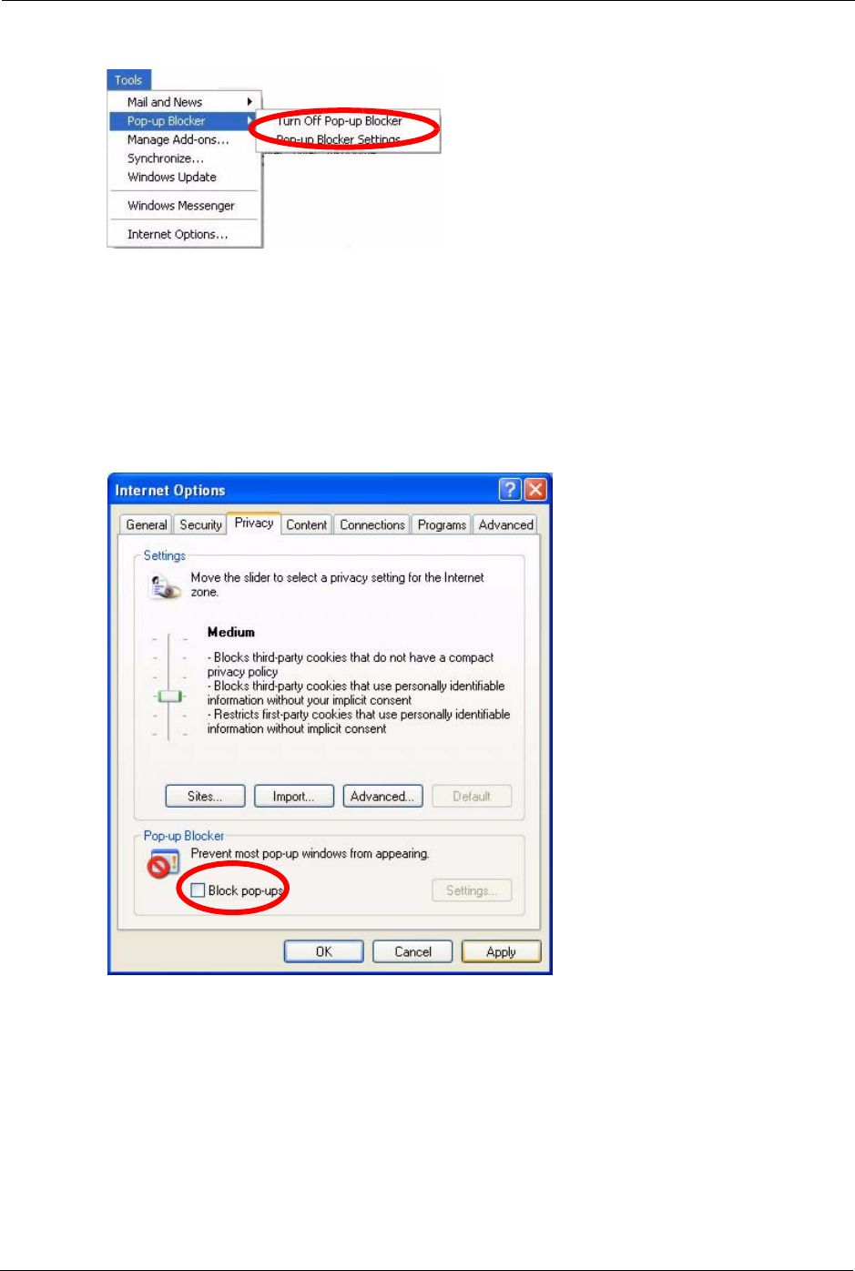
38.4.1.1 Internet Explorer Pop-up Blockers
You may have to disable pop-up blocking to log into your device.
Either disable pop-up blocking (enabled by default in Windows XP SP (Service Pack) 2) or
allow pop-up blocking and create an exception for your device’s IP address.
38.4.1.1.1 Disable pop-up Blockers
1In Internet Explorer, select Tools, Pop-up Blocker and then select Turn Off Pop-up
Blocker.
Table 121 Troubleshooting Accessing the Prestige
PROBLEM CORRECTIVE ACTION
I cannot
access the
Prestige.
The username is “admin”. The default password is “1234”. The Password and
Username fields are case-sensitive. Make sure that you enter the correct password
and username using the proper casing.
If you have changed the password and have now forgotten it, you will need to upload
the default configuration file. This restores all of the factory defaults including the
password.
I cannot
access the
web
configurator.
Make sure that there is not an SMT console session running.
Use the Prestige’s WAN IP address when configuring from the WAN. Refer to the
instructions on checking your WAN connection.
Use the Prestige’s LAN IP address when configuring from the LAN. Refer to for
instructions on checking your LAN connection.
Check that you have enabled web service access. If you have configured a secured
client IP address, your computer’s IP address must match it. Refer to the chapter on
remote management for details.
Your computer’s and the Prestige’s IP addresses must be on the same subnet for LAN
access.
If you changed the Prestige’s LAN IP address, then enter the new one as the URL.
Remove any filters in SMT menu 3.1 (LAN) or menu 11.5 (WAN) that block web
service.
See the following section to check that pop-up windows, JavaScripts and Java
permissions are allowed.
P-660H/HW/W-T Series User’ Guide
345 Chapter 38 Troubleshooting
Figure 223 Pop-up Blocker
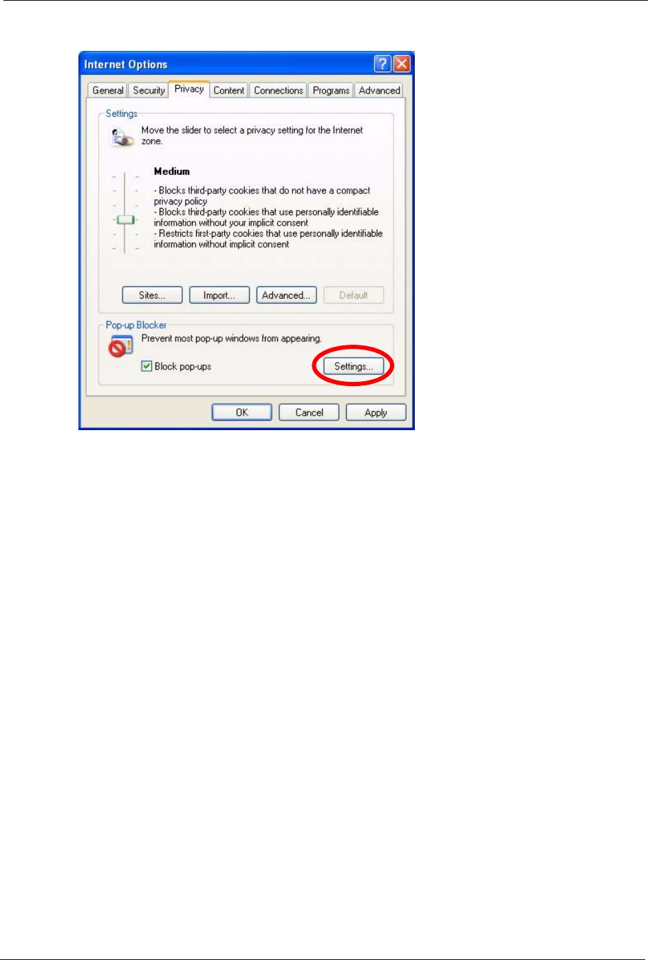
You can also check if pop-up blocking is disabled in the Pop-up Blocker section in the
Privacy tab.
1In Internet Explorer, select Tools, Internet Options, Privacy.
2Clear the Block pop-ups check box in the Pop-up Blocker section of the screen. This
disables any web pop-up blockers you may have enabled.
Figure 224 Internet Options
3Click Apply to save this setting.
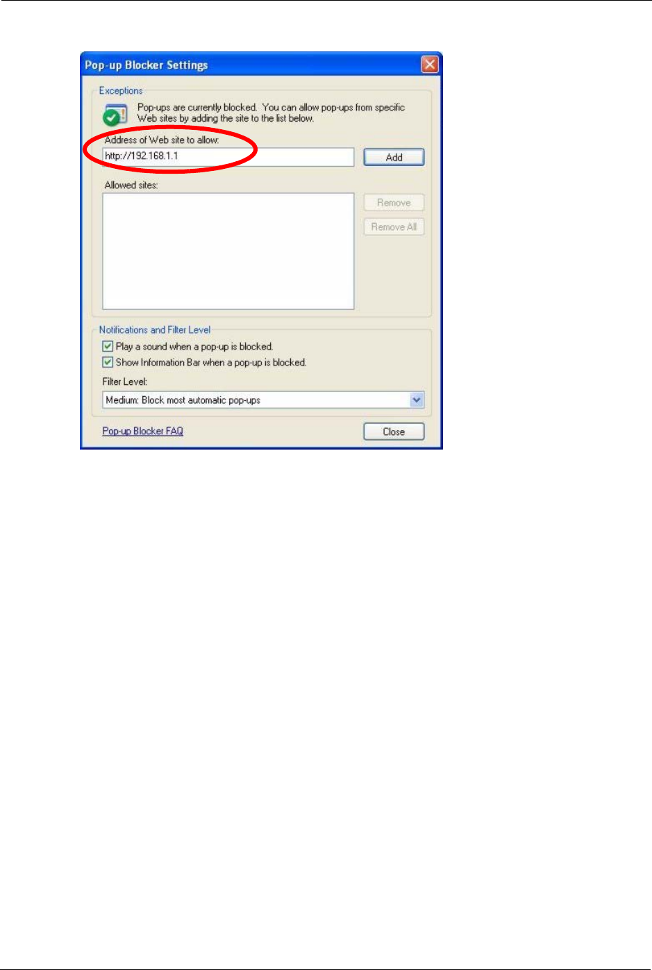
38.4.1.1.2 Enable pop-up Blockers with Exceptions
Alternatively, if you only want to allow pop-up windows from your device, see the following
steps.
1In Internet Explorer, select Tools, Internet Options and then the Privacy tab.
2Select Settings…to open the Pop-up Blocker Settings screen.
P-660H/HW/W-T Series User’ Guide
Chapter 38 Troubleshooting 346
Figure 225 Internet Options
3Type the IP address of your device (the web page that you do not want to have blocked)
with the prefix “http://”. For example, http://192.168.1.1.
4Click Add to move the IP address to the list of Allowed sites.
P-660H/HW/W-T Series User’ Guide
347 Chapter 38 Troubleshooting
Figure 226 Pop-up Blocker Settings
5Click Close to return to the Privacy screen.
6Click Apply to save this setting.
38.4.1.2 JavaScripts
If pages of the web configurator do not display properly in Internet Explorer, check that
JavaScripts are allowed.
1In Internet Explorer, click Tools, Internet Options and then the Security tab.
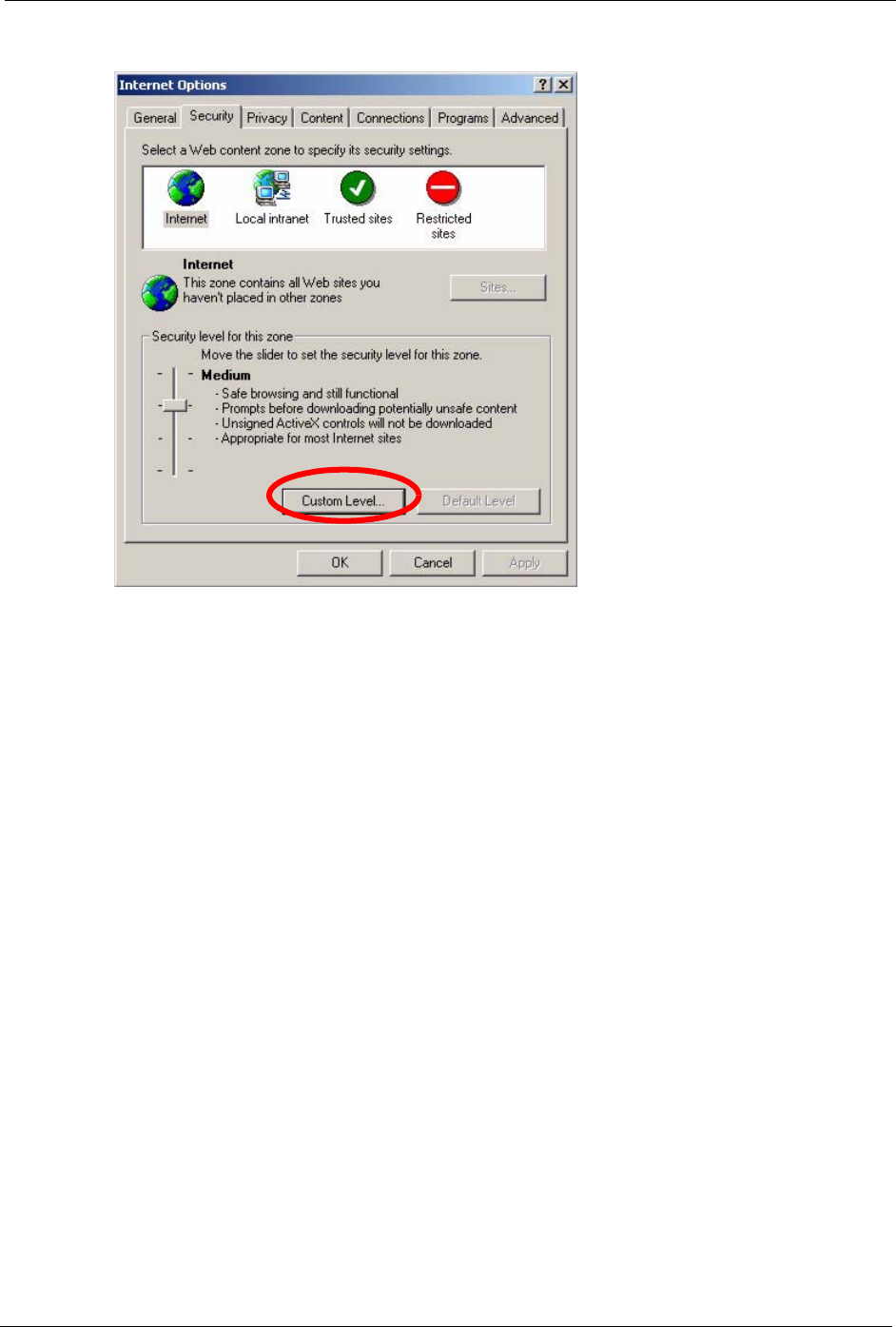
P-660H/HW/W-T Series User’ Guide
Chapter 38 Troubleshooting 348
Figure 227 Internet Options
2Click the Custom Level... button.
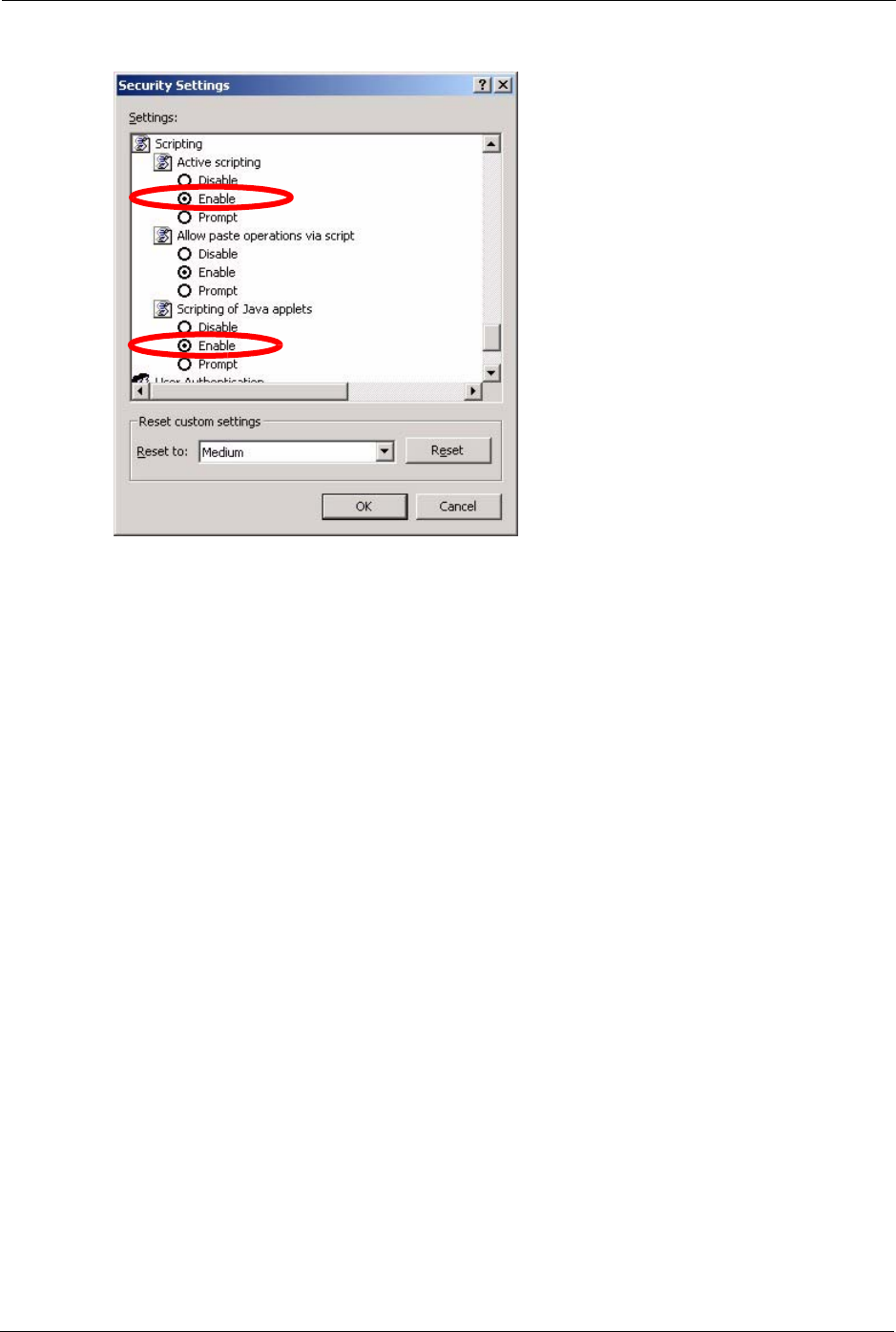
3Scroll down to Scripting.
4Under Active scripting make sure that Enable is selected (the default).
5Under Scripting of Java applets make sure that Enable is selected (the default).
6Click OK to close the window.
P-660H/HW/W-T Series User’ Guide
349 Chapter 38 Troubleshooting
Figure 228 Security Settings - Java Scripting
38.4.1.3 Java Permissions
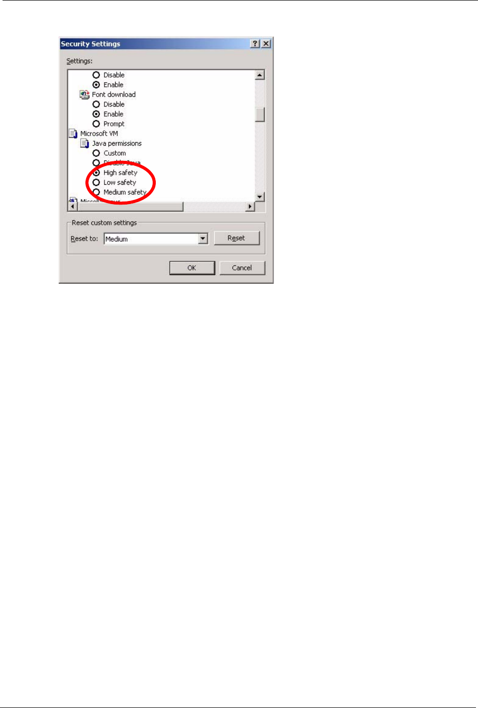
1From Internet Explorer, click Tools, Internet Options and then the Security tab.
2Click the Custom Level... button.
3Scroll down to Microsoft VM.
4Under Java permissions make sure that a safety level is selected.
5Click OK to close the window.
P-660H/HW/W-T Series User’ Guide
Chapter 38 Troubleshooting 350
Figure 229 Security Settings - Java
38.4.1.3.1 JAVA (Sun)
1From Internet Explorer, click Tools, Internet Options and then the Advanced tab.
2make sure that Use Java 2 for <applet> under Java (Sun) is selected.
3Click OK to close the window.
P-660H/HW/W-T Series User’ Guide
351 Chapter 38 Troubleshooting
Figure 230 Java (Sun)
38.4.2 ActiveX Controls in Internet Explorer
If ActiveX is disabled, you will not be able to download ActiveX controls or to use Trend
Micro Security Services. Make sure that ActiveX controls are allowed in Internet Explorer.
Screen shots for Internet Explorer 6 are shown. Steps may vary depending on your version of
Internet Explorer.
1In Internet Explorer, click Tools, Internet Options and then the Security tab.
2In the Internet Options window, click Custom Level.
P-660H/HW/W-T Series User’ Guide
Chapter 38 Troubleshooting 352
Figure 231 Internet Options Security
3Scroll down to ActiveX controls and plug-ins.
4Under Download signed ActiveX controls select the Prompt radio button.
5Under Run ActiveX controls and plug-ins make sure the Enable radio button is
selected.
6Then click the OK button.
P-660H/HW/W-T Series User’ Guide
353 Chapter 38 Troubleshooting
Figure 232 Security Setting ActiveX Controls

P-660H/HW/W-T Series User’ Guide
Appendix A 354
Appendix A
Product Specifications
See also the Introduction chapter for a general overview of the key features.
Specification Tables
Table 122 Device
Default IP Address 192.168.1.1
Default Subnet Mask 255.255.255.0 (24 bits)
Default Password 1234
DHCP Pool 192.168.1.32 to 192.168.1.64
Dimensions (W x D x H) 180 x 128 x 36 mm
Power Specification 12VDC 1A
Built-in Switch (P-660H/
P-660HW)
Four auto-negotiating, auto MDI/MDI-X 10/100 Mbps RJ-45 Ethernet ports
Operation Temperature 0º C ~ 40º C
Storage Temperature -20º ~ 60º C
Operation Humidity 20% ~ 85% RH
Storage Humidity 10% ~ 90% RH

P-660H/HW/W-T Series User’ Guide
355 Appendix A
Table 123 Firmware
ADSL Standards Multi-Mode standard (ANSI T1.413,Issue 2; G.dmt(G.992.1); G.lite(G992.2)).
ADSL2 G.dmt.bis (G.992.3)
ADSL2 G.lite.bis (G.992.4)
ADSL2+ (G.992.5)
Reach-Extended ADSL (RE ADSL)
SRA (Seamless Rate Adaptation)
Auto-negotiating rate adaptation
ADSL physical connection ATM AAL5 (ATM Adaptation Layer type 5)
Multi-protocol over AAL5 (RFC2684/1483)
PPP over ATM AAL5 (RFC 2364)
PPP over Ethernet (RFC 2516)
RFC 1483 encapsulation over ATM
MAC encapsulated routing (ENET encapsulation)
VC-based and LLC-based multiplexing
Up to 8 PVCs (Permanent Virtual Circuits)
I.610 F4/F5 OAM
Other Protocol Support PPP (Point-to-Point Protocol) link layer protocol.
Transparent bridging for unsupported network layer protocols.
DHCP Server/Client/Relay
RIP I/RIP II
ICMP
ATM QoS
SNMP v1 and v2c with MIB II support (RFC 1213)
IP Multicasting IGMP v1 and v2
IGMP Proxy
UPnP
Management Embedded Web Configurator
Menu-driven SMT (System Management Terminal) management
CLI (Command Line Interpreter)
Remote Management via Telnet or Web
SNMP manageable
FTP/TFTP for firmware downloading, configuration backup and restoration.
Syslog
Built-in Diagnostic Tools for FLASH memory, ADSL circuitry, RAM and LAN
port
MAP - “Multimedia Auto Provisioner” (multimedia installation tutorial and
automatic configurator) (P-660HW)
Wireless (P-660HW/ P-
660W)
IEEE 802.11g compliance
Frequency Range: 2.4 GHz
Advanced Orthogonal Frequency Division Multiplexing (OFDM)
Data Rates: 54Mbps and Auto Fallback
Wired Equivalent Privacy (WEP) Data Encryption 64/128/256 bit
WLAN bridge to LAN
Up to 32 MAC address filters
WPA(2), WPA(2)-PSK
IEEE 802.1x
Store up to 32 built-in user profiles using EAP-MD5 (Local User Database)
External RADIUS server using EAP-MD5, TLS, TTLS

P-660H/HW/W-T Series User’ Guide
Appendix A 356
Firewall Stateful Packet Inspection.
Prevent Denial of Service attacks such as Ping of Death, SYN Flood, LAND,
Smurf etc.
Real time E-mail alerts.
Reports and logs.
NAT/SUA Port Forwarding
1024 NAT sessions
Multimedia application
PPTP under NAT/SUA
IPSec passthrough
SIP ALG passthrough
VPN passthrough
Content Filtering Web page blocking by URL keyword.
Static Routes 16 IP and 4 Bridge
Other Features Any IP
Zero Configuration (VC auto-hunting)
Traffic Redirect
Dynamic DNS
IP Alias
IP Policy Routing
MBM (Multimedia Bandwidth Management) QoS (Quality of Service)
Table 123 Firmware (continued)

P-660H/HW/W-T Series User’ Guide
357 Appendix A
P-660H/HW/W-T Series User’ Guide
Appendix B 358
APPENDIX B
Wall-mounting Instructions
Do the following to hang your Prestige on a wall.
Note: See the product specifications appendix for the size of screws to use and how
far apart to place them.
1Locate a high position on wall that is free of obstructions. Use a sturdy wall.
2Drill two holes for the screws. Make sure the distance between the centers of the holes
matches what is listed in the product specifications appendix.
Note: Be careful to avoid damaging pipes or cables located inside the wall when
drilling holes for the screws.
3Do not screw the screws all the way into the wall. Leave a small gap of about 0.5 cm
between the heads of the screws and the wall.
4Make sure the screws are snugly fastened to the wall. They need to hold the weight of the
Prestige with the connection cables.
5Align the holes on the back of the Prestige with the screws on the wall. Hang the Prestige
on the screws.
Figure 233 Wall-mounting Example

P-660H/HW/W-T Series User’ Guide
359 Appendix B

P-660H/HW/W-T Series User’ Guide
Appendix C 360
Appendix C
Setting up Your Computer’s IP Address
All computers must have a 10M or 100M Ethernet adapter card and TCP/IP installed.
Windows 95/98/Me/NT/2000/XP, Macintosh OS 7 and later operating systems and all
versions of UNIX/LINUX include the software components you need to install and use TCP/
IP on your computer. Windows 3.1 requires the purchase of a third-party TCP/IP application
package.
TCP/IP should already be installed on computers using Windows NT/2000/XP, Macintosh OS
7 and later operating systems.
After the appropriate TCP/IP components are installed, configure the TCP/IP settings in order
to "communicate" with your network.
If you manually assign IP information instead of using dynamic assignment, make sure that
your computers have IP addresses that place them in the same subnet as the Prestige’s LAN
port.
Windows 95/98/Me
Click Start, Settings, Control Panel and double-click the Network icon to open the Network
window.
P-660H/HW/W-T Series User’ Guide
361 Appendix C
Figure 234 WIndows 95/98/Me: Network: Configuration
Installing Components
The Network window Configuration tab displays a list of installed components. You need a
network adapter, the TCP/IP protocol and Client for Microsoft Networks.
If you need the adapter:
1In the Network window, click Add.
2Select Adapter and then click Add.
3Select the manufacturer and model of your network adapter and then click OK.
If you need TCP/IP:
1In the Network window, click Add.
2Select Protocol and then click Add.
3Select Microsoft from the list of manufacturers.
4Select TCP/IP from the list of network protocols and then click OK.
If you need Client for Microsoft Networks:
1Click Add.
2Select Client and then click Add.
P-660H/HW/W-T Series User’ Guide
Appendix C 362
3Select Microsoft from the list of manufacturers.
4Select Client for Microsoft Networks from the list of network clients and then click
OK.
5Restart your computer so the changes you made take effect.
Configuring
1In the Network window Configuration tab, select your network adapter's TCP/IP entry
and click Properties
2Click the IP Address tab.
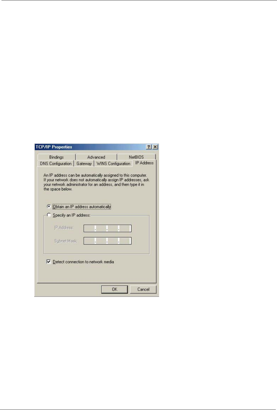
• If your IP address is dynamic, select Obtain an IP address automatically.
• If you have a static IP address, select Specify an IP address and type your
information into the IP Address and Subnet Mask fields.
Figure 235 Windows 95/98/Me: TCP/IP Properties: IP Address
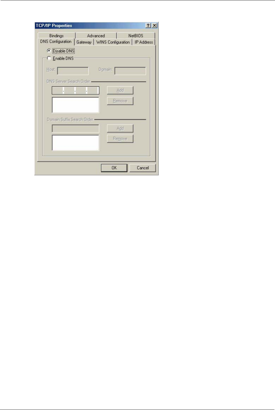
3Click the DNS Configuration tab.
• If you do not know your DNS information, select Disable DNS.
• If you know your DNS information, select Enable DNS and type the information in
the fields below (you may not need to fill them all in).
P-660H/HW/W-T Series User’ Guide
363 Appendix C
Figure 236 Windows 95/98/Me: TCP/IP Properties: DNS Configuration
4Click the Gateway tab.
• If you do not know your gateway’s IP address, remove previously installed
gateways.
• If you have a gateway IP address, type it in the New gateway field and click Add.
5Click OK to save and close the TCP/IP Properties window.
6Click OK to close the Network window. Insert the Windows CD if prompted.
7Turn on your Prestige and restart your computer when prompted.
Verifying Settings
1Click Start and then Run.
2In the Run window, type "winipcfg" and then click OK to open the IP Configuration
window.
3Select your network adapter. You should see your computer's IP address, subnet mask
and default gateway.
Windows 2000/NT/XP
The following example figures use the default Windows XP GUI theme.
1Click start (Start in Windows 2000/NT), Settings, Control Panel.
P-660H/HW/W-T Series User’ Guide
Appendix C 364
Figure 237 Windows XP: Start Menu
2In the Control Panel, double-click Network Connections (Network and Dial-up
Connections in Windows 2000/NT).
Figure 238 Windows XP: Control Panel
3Right-click Local Area Connection and then click Properties.
P-660H/HW/W-T Series User’ Guide
365 Appendix C
Figure 239 Windows XP: Control Panel: Network Connections: Properties
4Select Internet Protocol (TCP/IP) (under the General tab in Win XP) and then click
Properties.
Figure 240 Windows XP: Local Area Connection Properties
5The Internet Protocol TCP/IP Properties window opens (the General tab in Windows
XP).
• If you have a dynamic IP address click Obtain an IP address automatically.
• If you have a static IP address click Use the following IP Address and fill in the IP
address, Subnet mask, and Default gateway fields.
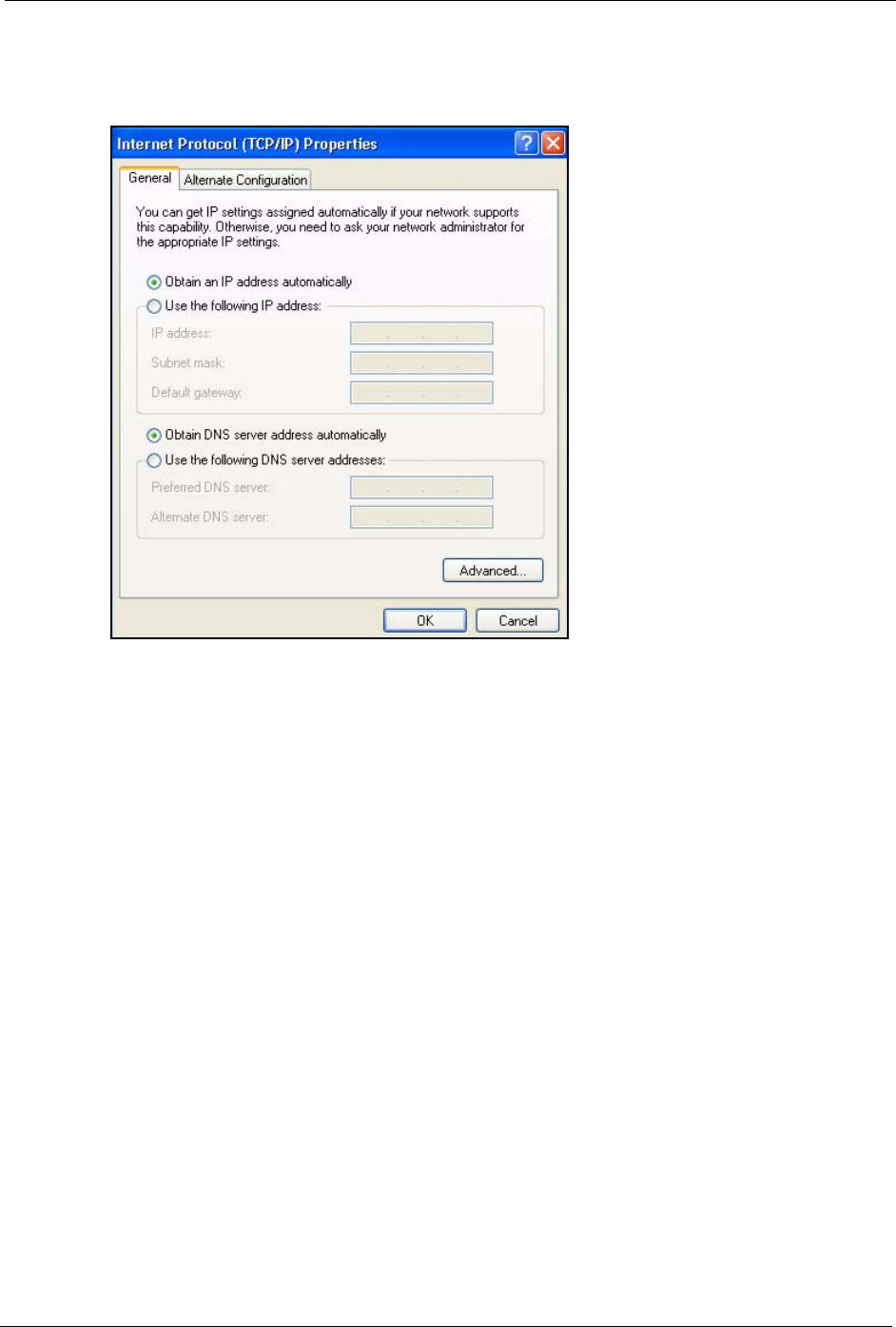
P-660H/HW/W-T Series User’ Guide
Appendix C 366
• Click Advanced.
Figure 241 Windows XP: Internet Protocol (TCP/IP) Properties
6 If you do not know your gateway's IP address, remove any previously installed gateways
in the IP Settings tab and click OK.
Do one or more of the following if you want to configure additional IP addresses:
•In the IP Settings tab, in IP addresses, click Add.
•In TCP/IP Address, type an IP address in IP address and a subnet mask in Subnet
mask, and then click Add.
• Repeat the above two steps for each IP address you want to add.
• Configure additional default gateways in the IP Settings tab by clicking Add in
Default gateways.
•In TCP/IP Gateway Address, type the IP address of the default gateway in
Gateway. To manually configure a default metric (the number of transmission
hops), clear the Automatic metric check box and type a metric in Metric.
• Click Add.
• Repeat the previous three steps for each default gateway you want to add.
• Click OK when finished.
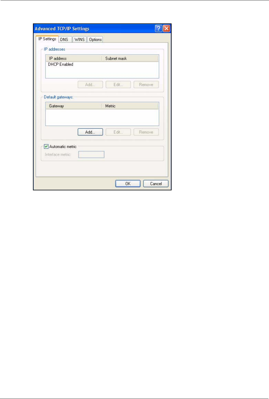
P-660H/HW/W-T Series User’ Guide
367 Appendix C
Figure 242 Windows XP: Advanced TCP/IP Properties
7In the Internet Protocol TCP/IP Properties window (the General tab in Windows XP):
• Click Obtain DNS server address automatically if you do not know your DNS
server IP address(es).
• If you know your DNS server IP address(es), click Use the following DNS server
addresses, and type them in the Preferred DNS server and Alternate DNS server
fields.
If you have previously configured DNS servers, click Advanced and then the DNS
tab to order them.
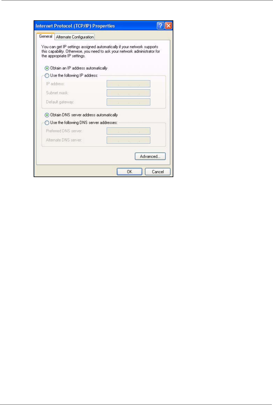
P-660H/HW/W-T Series User’ Guide
Appendix C 368
Figure 243 Windows XP: Internet Protocol (TCP/IP) Properties
8Click OK to close the Internet Protocol (TCP/IP) Properties window.
9Click Close (OK in Windows 2000/NT) to close the Local Area Connection Properties
window.
10 Close the Network Connections window (Network and Dial-up Connections in
Windows 2000/NT).
11Turn on your Prestige and restart your computer (if prompted).
Verifying Settings
1Click Start, All Programs, Accessories and then Command Prompt.
2In the Command Prompt window, type "ipconfig" and then press [ENTER]. You can
also open Network Connections, right-click a network connection, click Status and then
click the Support tab.
Macintosh OS 8/9
1Click the Apple menu, Control Panel and double-click TCP/IP to open the TCP/IP
Control Panel.
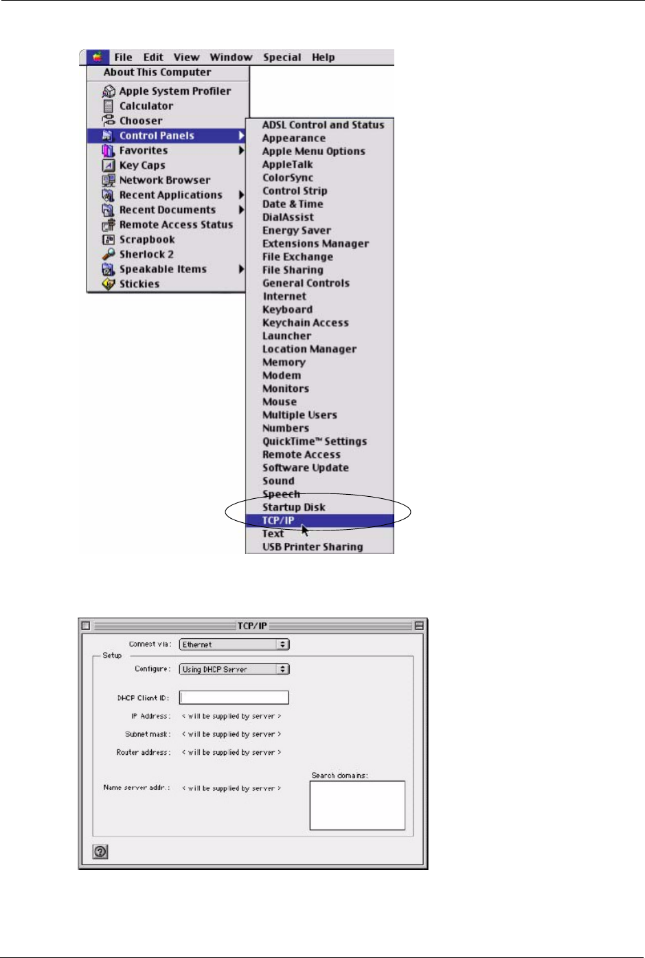
P-660H/HW/W-T Series User’ Guide
369 Appendix C
Figure 244 Macintosh OS 8/9: Apple Menu
2Select Ethernet built-in from the Connect via list.
Figure 245 Macintosh OS 8/9: TCP/IP
3For dynamically assigned settings, select Using DHCP Server from the Configure: list.
P-660H/HW/W-T Series User’ Guide
Appendix C 370
4For statically assigned settings, do the following:
•From the Configure box, select Manually.
• Type your IP address in the IP Address box.
• Type your subnet mask in the Subnet mask box.
• Type the IP address of your Prestige in the Router address box.
5Close the TCP/IP Control Panel.
6Click Save if prompted, to save changes to your configuration.
7Turn on your Prestige and restart your computer (if prompted).
Verifying Settings
Check your TCP/IP properties in the TCP/IP Control Panel window.
Macintosh OS X
1Click the Apple menu, and click System Preferences to open the System Preferences
window.
Figure 246 Macintosh OS X: Apple Menu
2Click Network in the icon bar.
• Select Automatic from the Location list.
• Select Built-in Ethernet from the Show list.
• Click the TCP/IP tab.
3For dynamically assigned settings, select Using DHCP from the Configure list.
P-660H/HW/W-T Series User’ Guide
371 Appendix C
Figure 247 Macintosh OS X: Network
4For statically assigned settings, do the following:
•From the Configure box, select Manually.
• Type your IP address in the IP Address box.
• Type your subnet mask in the Subnet mask box.
• Type the IP address of your Prestige in the Router address box.
5Click Apply Now and close the window.
6Turn on your Prestige and restart your computer (if prompted).
Verifying Settings
Check your TCP/IP properties in the Network window.
Linux
This section shows you how to configure your computer’s TCP/IP settings in Red Hat Linux
9.0. Procedure, screens and file location may vary depending on your Linux distribution and
release version.
P-660H/HW/W-T Series User’ Guide
Appendix C 372
Note: Make sure you are logged in as the root administrator.
Using the K Desktop Environment (KDE)
Follow the steps below to configure your computer IP address using the KDE.
1Click the Red Hat button (located on the bottom left corner), select System Setting and
click Network.
Figure 248 Red Hat 9.0: KDE: Network Configuration: Devices
2Double-click on the profile of the network card you wish to configure. The Ethernet
Device General screen displays as shown.
Figure 249 Red Hat 9.0: KDE: Ethernet Device: General
P-660H/HW/W-T Series User’ Guide
373 Appendix C
• If you have a dynamic IP address click Automatically obtain IP address settings
with and select dhcp from the drop down list.
• If you have a static IP address click Statically set IP Addresses and fill in the
Address, Subnet mask, and Default Gateway Address fields.
3Click OK to save the changes and close the Ethernet Device General screen.
4If you know your DNS server IP address(es), click the DNS tab in the Network
Configuration screen. Enter the DNS server information in the fields provided.
Figure 250 Red Hat 9.0: KDE: Network Configuration: DNS
5Click the Devices tab.
6Click the Activate button to apply the changes. The following screen displays. Click Ye s
to save the changes in all screens.
Figure 251 Red Hat 9.0: KDE: Network Configuration: Activate
7After the network card restart process is complete, make sure the Status is Active in the
Network Configuration screen.
Using Configuration Files
Follow the steps below to edit the network configuration files and set your computer IP
address.

P-660H/HW/W-T Series User’ Guide
Appendix C 374
1Assuming that you have only one network card on the computer, locate the ifconfig-
eth0 configuration file (where eth0 is the name of the Ethernet card). Open the
configuration file with any plain text editor.
• If you have a dynamic IP address, enter dhcp in the BOOTPROTO= field. The
following figure shows an example.
Figure 252 Red Hat 9.0: Dynamic IP Address Setting in ifconfig-eth0
• If you have a static IP address, enter static in the BOOTPROTO= field. Type
IPADDR= followed by the IP address (in dotted decimal notation) and type
NETMASK= followed by the subnet mask. The following example shows an example
where the static IP address is 192.168.1.10 and the subnet mask is 255.255.255.0.
Figure 253 Red Hat 9.0: Static IP Address Setting in ifconfig-eth0
2If you know your DNS server IP address(es), enter the DNS server information in the
resolv.conf file in the /etc directory. The following figure shows an example where
two DNS server IP addresses are specified.
Figure 254 Red Hat 9.0: DNS Settings in resolv.conf
3After you edit and save the configuration files, you must restart the network card. Enter
./network restart in the /etc/rc.d/init.d directory. The following figure
shows an example.
DEVICE=eth0
ONBOOT=yes
BOOTPROTO=dhcp
USERCTL=no
PEERDNS=yes
TYPE=Ethernet
DEVICE=eth0
ONBOOT=yes
BOOTPROTO=static
IPADDR=192.168.1.10
NETMASK=255.255.255.0
USERCTL=no
PEERDNS=yes
TYPE=Ethernet
nameserver 172.23.5.1
nameserver 172.23.5.2

P-660H/HW/W-T Series User’ Guide
375 Appendix C
Figure 255 Red Hat 9.0: Restart Ethernet Card
Verifying Settings
Enter ifconfig in a terminal screen to check your TCP/IP properties.
Figure 256 Red Hat 9.0: Checking TCP/IP Properties
[root@localhost init.d]# network restart
Shutting down interface eth0: [OK]
Shutting down loopback interface: [OK]
Setting network parameters: [OK]
Bringing up loopback interface: [OK]
Bringing up interface eth0: [OK]
[root@localhost]# ifconfig
eth0 Link encap:Ethernet HWaddr 00:50:BA:72:5B:44
inet addr:172.23.19.129 Bcast:172.23.19.255 Mask:255.255.255.0
UP BROADCAST RUNNING MULTICAST MTU:1500 Metric:1
RX packets:717 errors:0 dropped:0 overruns:0 frame:0
TX packets:13 errors:0 dropped:0 overruns:0 carrier:0
collisions:0 txqueuelen:100
RX bytes:730412 (713.2 Kb) TX bytes:1570 (1.5 Kb)
Interrupt:10 Base address:0x1000
[root@localhost]#

P-660H/HW/W-T Series User’ Guide
Appendix D 376
Appendix D
IP Subnetting
IP Addressing
Routers “route” based on the network number. The router that delivers the data packet to the
correct destination host uses the host ID.
IP Classes
An IP address is made up of four octets (eight bits), written in dotted decimal notation, for
example, 192.168.1.1. IP addresses are categorized into different classes. The class of an
address depends on the value of its first octet.
• Class “A” addresses have a 0 in the left most bit. In a class “A” address the first octet is
the network number and the remaining three octets make up the host ID.
• Class “B” addresses have a 1 in the left most bit and a 0 in the next left most bit. In a class
“B” address the first two octets make up the network number and the two remaining
octets make up the host ID.
• Class “C” addresses begin (starting from the left) with 1 1 0. In a class “C” address the
first three octets make up the network number and the last octet is the host ID.
• Class “D” addresses begin with 1 1 1 0. Class “D” addresses are used for multicasting.
(There is also a class “E” address. It is reserved for future use.)
Note: Host IDs of all zeros or all ones are not allowed.
Therefore:
A class “C” network (8 host bits) can have 28 –2 or 254 hosts.
A class “B” address (16 host bits) can have 216 –2 or 65534 hosts.
A class “A” address (24 host bits) can have 224 –2 hosts (approximately 16 million hosts).
Table 124 Classes of IP Addresses
IP ADDRESS: OCTET 1 OCTET 2 OCTET 3 OCTET 4
Class A 0Network number Host ID Host ID Host ID
Class B 10 Network number Network number Host ID Host ID
Class C 110 Network number Network number Network number Host ID

P-660H/HW/W-T Series User’ Guide
377 Appendix D
Since the first octet of a class “A” IP address must contain a “0”, the first octet of a class “A”
address can have a value of 0 to 127.
Similarly the first octet of a class “B” must begin with “10”, therefore the first octet of a class
“B” address has a valid range of 128 to 191. The first octet of a class “C” address begins with
“110”, and therefore has a range of 192 to 223.
Subnet Masks
A subnet mask is used to determine which bits are part of the network number, and which bits
are part of the host ID (using a logical AND operation). A subnet mask has 32 is a “1” then
the corresponding bit in the IP address is part of the network number. If a bit in the subnet
mask is “0” then the corresponding bit in the IP address is part of the host ID.
Subnet masks are expressed in dotted decimal notation just as IP addresses are. The “natural”
masks for class A, B and C IP addresses are as follows.
Subnetting
With subnetting, the class arrangement of an IP address is ignored. For example, a class C
address no longer has to have 24 bits of network number and 8 bits of host ID. With
subnetting, some of the host ID bits are converted into network number bits. By convention,
subnet masks always consist of a continuous sequence of ones beginning from the left most bit
of the mask, followed by a continuous sequence of zeros, for a total number of 32 bits.
Table 125 Allowed IP Address Range By Class
CLASS ALLOWED RANGE OF FIRST OCTET
(BINARY)
ALLOWED RANGE OF FIRST OCTET
(DECIMAL)
Class A 00000000 to 01111111 0 to 127
Class B 10000000 to 10111111 128 to 191
Class C 11000000 to 11011111 192 to 223
Class D 11100000 to 11101111 224 to 239
Table 126 “Natural” Masks
CLASS NATURAL MASK
A255.0.0.0
B255.255.0.0
C255.255.255.0

P-660H/HW/W-T Series User’ Guide
Appendix D 378
Since the mask is always a continuous number of ones beginning from the left, followed by a
continuous number of zeros for the remainder of the 32 bit mask, you can simply specify the
number of ones instead of writing the value of each octet. This is usually specified by writing
a “/” followed by the number of bits in the mask after the address.
For example, 192.1.1.0 /25 is equivalent to saying 192.1.1.0 with mask 255.255.255.128.
The following table shows all possible subnet masks for a class “C” address using both
notations.
The first mask shown is the class “C” natural mask. Normally if no mask is specified it is
understood that the natural mask is being used.
Example: Two Subnets
As an example, you have a class “C” address 192.168.1.0 with subnet mask of 255.255.255.0.
The first three octets of the address make up the network number (class “C”). You want to
have two separate networks.
Divide the network 192.168.1.0 into two separate subnets by converting one of the host ID bits
of the IP address to a network number bit. The “borrowed” host ID bit can be either “0” or “1”
thus giving two subnets; 192.168.1.0 with mask 255.255.255.128 and 192.168.1.128 with
mask 255.255.255.128.
Table 127 Alternative Subnet Mask Notation
SUBNET MASK SUBNET MASK “1” BITS LAST OCTET BIT VALUE
255.255.255.0 /24 0000 0000
255.255.255.128 /25 1000 0000
255.255.255.192 /26 1100 0000
255.255.255.224 /27 1110 0000
255.255.255.240 /28 1111 0000
255.255.255.248 /29 1111 1000
255.255.255.252 /30 1111 1100
Table 128 Two Subnets Example
IP/SUBNET MASK NETWORK NUMBER HOST ID
IP Address 192.168.1. 0
IP Address (Binary) 11000000.10101000.00000001. 00000000
Subnet Mask 255.255.255. 0
Subnet Mask (Binary) 11111111.11111111.11111111. 00000000
P-660H/HW/W-T Series User’ Guide
379 Appendix D
Note: In the following charts, shaded/bolded last octet bit values indicate host ID bits
“borrowed” to form network ID bits. The number of “borrowed” host ID bits determines
the number of subnets you can have. The remaining number of host ID bits (after
“borrowing”) determines the number of hosts you can have on each subnet.
The remaining 7 bits determine the number of hosts each subnet can have. Host IDs of all
zeros represent the subnet itself and host IDs of all ones are the broadcast address for that
subnet, so the actual number of hosts available on each subnet in the example above is 27 – 2
or 126 hosts for each subnet.
192.168.1.0 with mask 255.255.255.128 is the subnet itself, and 192.168.1.127 with mask
255.255.255.128 is the directed broadcast address for the first subnet. Therefore, the lowest IP
address that can be assigned to an actual host for the first subnet is 192.168.1.1 and the highest
is 192.168.1.126. Similarly the host ID range for the second subnet is 192.168.1.129 to
192.168.1.254.
Table 129 Subnet 1
IP/SUBNET MASK NETWORK NUMBER LAST OCTET BIT
VALUE
IP Address 192.168.1. 0
IP Address (Binary) 11000000.10101000.00000001. 00000000
Subnet Mask 255.255.255. 128
Subnet Mask (Binary) 11111111.11111111.11111111. 10000000
Subnet Address: 192.168.1.0 Lowest Host ID: 192.168.1.1
Broadcast Address:
192.168.1.127
Highest Host ID: 192.168.1.126
Table 130 Subnet 2
IP/SUBNET MASK NETWORK NUMBER LAST OCTET BIT VALUE
IP Address 192.168.1. 128
IP Address (Binary) 11000000.10101000.00000001. 10000000
Subnet Mask 255.255.255. 128
Subnet Mask (Binary) 11111111.11111111.11111111. 10000000
Subnet Address:
192.168.1.128
Lowest Host ID: 192.168.1.129
Broadcast Address:
192.168.1.255
Highest Host ID: 192.168.1.254
P-660H/HW/W-T Series User’ Guide
Appendix D 380
Example: Four Subnets
The above example illustrated using a 25-bit subnet mask to divide a class “C” address space
into two subnets. Similarly to divide a class “C” address into four subnets, you need to
“borrow” two host ID bits to give four possible combinations of 00, 01, 10 and 11. The subnet
mask is 26 bits (11111111.11111111.11111111.11000000) or 255.255.255.192. Each subnet
contains 6 host ID bits, giving 26-2 or 62 hosts for each subnet (all 0’s is the subnet itself, all
1’s is the broadcast address on the subnet).
Table 131 Subnet 1
IP/SUBNET MASK NETWORK NUMBER LAST OCTET BIT
VALUE
IP Address 192.168.1. 0
IP Address (Binary) 11000000.10101000.00000001. 00000000
Subnet Mask (Binary) 11111111.11111111.11111111. 11000000
Subnet Address: 192.168.1.0 Lowest Host ID: 192.168.1.1
Broadcast Address:
192.168.1.63
Highest Host ID: 192.168.1.62
Table 132 Subnet 2
IP/SUBNET MASK NETWORK NUMBER LAST OCTET BIT
VALUE
IP Address 192.168.1. 64
IP Address (Binary) 11000000.10101000.00000001. 01000000
Subnet Mask (Binary) 11111111.11111111.11111111. 11000000
Subnet Address: 192.168.1.64 Lowest Host ID: 192.168.1.65
Broadcast Address: 192.168.1.127 Highest Host ID: 192.168.1.126
Table 133 Subnet 3
IP/SUBNET MASK NETWORK NUMBER LAST OCTET BIT
VALUE
IP Address 192.168.1. 128
IP Address (Binary) 11000000.10101000.00000001. 10000000
Subnet Mask (Binary) 11111111.11111111.11111111. 11000000
Subnet Address:
192.168.1.128
Lowest Host ID: 192.168.1.129
Broadcast Address:
192.168.1.191
Highest Host ID: 192.168.1.190
P-660H/HW/W-T Series User’ Guide
381 Appendix D
Example Eight Subnets
Similarly use a 27-bit mask to create 8 subnets (001, 010, 011, 100, 101, 110).
The following table shows class C IP address last octet values for each subnet.
The following table is a summary for class “C” subnet planning.
Table 134 Subnet 4
IP/SUBNET MASK NETWORK NUMBER LAST OCTET BIT VALUE
IP Address 192.168.1. 192
IP Address (Binary) 11000000.10101000.00000001. 11000000
Subnet Mask (Binary) 11111111.11111111.11111111. 11000000
Subnet Address:
192.168.1.192
Lowest Host ID: 192.168.1.193
Broadcast Address:
192.168.1.255
Highest Host ID: 192.168.1.254
Table 135 Eight Subnets
SUBNET SUBNET ADDRESS FIRST ADDRESS LAST ADDRESS BROADCAST
ADDRESS
1 0 1 30 31
232 33 62 63
364 65 94 95
496 97 126 127
5128 129 158 159
6160 161 190 191
7192 193 222 223
8224 225 254 255
Table 136 Class C Subnet Planning
NO. “BORROWED” HOST
BITS SUBNET MASK NO. SUBNETS NO. HOSTS PER
SUBNET
1255.255.255.128 (/25) 2126
2255.255.255.192 (/26) 462
3255.255.255.224 (/27) 830
4255.255.255.240 (/28) 16 14
5255.255.255.248 (/29) 32 6
6255.255.255.252 (/30) 64 2
7255.255.255.254 (/31) 128 1

P-660H/HW/W-T Series User’ Guide
Appendix D 382
Subnetting With Class A and Class B Networks.
For class “A” and class “B” addresses the subnet mask also determines which bits are part of
the network number and which are part of the host ID.
A class “B” address has two host ID octets available for subnetting and a class “A” address has
three host ID octets (see Table 124 on page 376) available for subnetting.
The following table is a summary for class “B” subnet planning.
Table 137 Class B Subnet Planning
NO. “BORROWED” HOST
BITS SUBNET MASK NO. SUBNETS NO. HOSTS PER
SUBNET
1255.255.128.0 (/17) 232766
2255.255.192.0 (/18) 416382
3255.255.224.0 (/19) 88190
4255.255.240.0 (/20) 16 4094
5255.255.248.0 (/21) 32 2046
6255.255.252.0 (/22) 64 1022
7255.255.254.0 (/23) 128 510
8255.255.255.0 (/24) 256 254
9255.255.255.128 (/25) 512 126
10 255.255.255.192 (/26) 1024 62
11 255.255.255.224 (/27) 2048 30
12 255.255.255.240 (/28) 4096 14
13 255.255.255.248 (/29) 8192 6
14 255.255.255.252 (/30) 16384 2
15 255.255.255.254 (/31) 32768 1

P-660H/HW/W-T Series User’ Guide
383 Appendix D

P-660H/HW/W-T Series User’ Guide
Appendix E 384
Appendix E
Boot Commands
The BootModule AT commands execute from within the router’s bootup software, when
debug mode is selected before the main router firmware is started. When you start up your
Prestige, you are given a choice to go into debug mode by pressing a key at the prompt shown
in the following screen. In debug mode you have access to a series of boot module commands,
for example ATUR (for uploading firmware) and ATLC (for uploading the configuration file).
These are already discussed in the Firmware and Configuration File Maintenance chapter.
Figure 257 Option to Enter Debug Mode
Enter ATHE to view all available Prestige boot module commands as shown in the next
screen. ATBAx allows you to change the console port speed. The x denotes the number
preceding the colon to give the console port speed following the colon in the list of numbers
that follows; for example ATBA3 will give a console port speed of 9.6 Kbps. ATSE displays
the seed that is used to generate a password to turn on the debug flag in the firmware. The
ATSH command shows product related information such as boot module version, vendor
name, product model, RAS code revision, etc. ATGO allows you to continue booting the
system. Most other commands aid in advanced troubleshooting and should only be used by
qualified engineers.
Bootbase Version: V1.02 | 08/08/2001 15:40:50
RAM: Size = 16384 Kbytes
DRAM Post: Testing: 16384K OK
FLASH: Intel 16M
RAS Version: V3.50(WB.0)b3 | 08/08/2001 16:21:27
Press any key to enter debug mode within 3
seconds.
.................................................

P-660H/HW/W-T Series User’ Guide
385 Appendix E
Figure 258 Boot Module Commands
AT just answer OK
ATHE print help
ATBAx change baudrate. 1:38.4k, 2:19.2k, 3:9.6k 4:57.6k
5:115.2k
ATENx,(y) set BootExtension Debug Flag (y=password)
ATSE show the seed of password generator
ATTI(h,m,s) change system time to hour:min:sec or show
current time
ATDA(y,m,d) change system date to year/month/day or show
current date
ATDS dump RAS stack
ATDT dump Boot Module Common Area
ATDUx,y dump memory contents from address x for length y
ATRBx display the 8-bit value of address x
ATRWx display the 16-bit value of address x
ATRLx display the 32-bit value of address x
ATGO(x) run program at addr x or boot router
ATGR boot router
ATGT run Hardware Test Program
ATRTw,x,y(,z) RAM test level w, from address x to y (z
iterations)
ATSH dump manufacturer related data in ROM
ATDOx,y download from address x for length y to PC via
XMODEM
ATTD download router configuration to PC via XMODEM
ATUR upload router firmware to flash ROM
ATLC upload router configuration file to flash ROM
ATXSx xmodem select: x=0: CRC mode(default); x=1:
checksum mode
ATSR system reboot

P-660H/HW/W-T Series User’ Guide
Appendix F 386
Appendix F
Command Interpreter
The following describes how to use the command interpreter. Enter 24 in the main menu to
bring up the system maintenance menu. Enter 8 to go to Menu 24.8 - Command Interpreter
Mode. See the included disk or zyxel.com for more detailed information on these commands.
Note: Use of undocumented commands or misconfiguration can damage the unit and
possibly render it unusable.
Command Syntax
• The command keywords are in courier new font.
• Enter the command keywords exactly as shown, do not abbreviate.
• The required fields in a command are enclosed in angle brackets <>.
• The optional fields in a command are enclosed in square brackets [].
•The |symbol means or.
For example,
sys filter netbios config <type> <on|off>
means that you must specify the type of netbios filter and whether to turn it on or off.
Command Usage
A list of valid commands can be found by typing help or? at the command prompt. Always
type the full command. Type exit to return to the SMT main menu when finished.

P-660H/HW/W-T Series User’ Guide
387 Appendix F

P-660H/HW/W-T Series User’ Guide
Appendix G 388
Appendix G
Firewall Commands
The following describes the firewall commands.
Table 138 Firewall Commands
FUNCTION COMMAND DESCRIPTION
Firewall SetUp
config edit firewall active
<yes | no>
This command turns the firewall on or off.
config retrieve firewall This command returns the previously saved
firewall settings.
config save firewall This command saves the current firewall
settings.
Display
config display firewall This command shows the of all the firewall
settings including e-mail, attack, and the sets/
rules.
config display firewall set
<set #>
This command shows the current
configuration of a set; including timeout
values, name, default-permit, and etc.If you
don’t put use a number (#) after “set”,
information about all of the sets/rules appears.
config display firewall set
<set #> rule <rule #>
This command shows the current entries of a
rule in a firewall rule set.
config display firewall attack This command shows all of the attack
response settings.
config display firewall e-mail This command shows all of the e-mail
settings.
config display firewall? This command shows all of the available
firewall sub commands.
Edit
E-mail config edit firewall e-mail
mail-server <ip address of
mail server>
This command sets the IP address to which
the e-mail messages are sent.

P-660H/HW/W-T Series User’ Guide
389 Appendix G
config edit firewall e-mail
return-addr <e-mail address>
This command sets the source e-mail address
of the firewall e-mails.
config edit firewall e-mail
email-to <e-mail address>
This command sets the e-mail address to
which the firewall e-mails are sent.
config edit firewall e-mail
policy <full | hourly | daily |
weekly>
This command sets how frequently the firewall
log is sent via e-mail.
config edit firewall e-mail
day <sunday | monday | tuesday
| wednesday | thursday | friday
| saturday>
This command sets the day on which the
current firewall log is sent through e-mail if the
Prestige is set to send it on a weekly basis.
config edit firewall e-mail
hour <0-23>
This command sets the hour when the firewall
log is sent through e- mail if the Prestige is set
to send it on an hourly, daily or weekly basis.
config edit firewall e-mail
minute <0-59>
This command sets the minute of the hour for
the firewall log to be sent via e- mail if the
Prestige is set to send it on a hourly, daily or
weekly basis.
Attack config edit firewall attack
send-alert <yes | no>
This command enables or disables the
immediate sending of DOS attack notification
e-mail messages.
config edit firewall attack
block <yes | no>
Set this command to yes to block new traffic
after the tcp-max-incomplete threshold is
exceeded. Set it to no to delete the oldest half-
open session when traffic exceeds the tcp-
max-incomplete threshold.
config edit firewall attack
block-minute <0-255>
This command sets the number of minutes for
new sessions to be blocked when the tcp-
max-incomplete threshold is reached. This
command is only valid when block is set to
yes.
config edit firewall attack
minute-high <0-255>
This command sets the threshold rate of new
half-open sessions per minute where the
Prestige starts deleting old half-opened
sessions until it gets them down to the minute-
low threshold.
Table 138 Firewall Commands (continued)
FUNCTION COMMAND DESCRIPTION

P-660H/HW/W-T Series User’ Guide
Appendix G 390
config edit firewall attack
minute-low <0-255>
This command sets the threshold of half-open
sessions where the Prestige stops deleting
half-opened sessions.
config edit firewall attack
max-incomplete-high <0-255>
This command sets the threshold of half-open
sessions where the Prestige starts deleting old
half-opened sessions until it gets them down
to the max incomplete low.
config edit firewall attack
max-incomplete-low <0-255>
This command sets the threshold where the
Prestige stops deleting half-opened sessions.
config edit firewall attack
tcp-max-incomplete <0-255>
This command sets the threshold of half-open
TCP sessions with the same destination
where the Prestige starts dropping half-open
sessions to that destination.
Sets config edit firewall set <set
#> name <desired name>
This command sets a name to identify a
specified set.
Config edit firewall set <set
#> default-permit <forward |
block>
This command sets whether a packet is
dropped or allowed through, when it does not
meet a rule within the set.
Config edit firewall set <set
#> icmp-timeout <seconds>
This command sets the time period to allow an
ICMP session to wait for the ICMP response.
Config edit firewall set <set
#> udp-idle-timeout <seconds>
This command sets how long a UDP
connection is allowed to remain inactive
before the Prestige considers the connection
closed.
Config edit firewall set <set
#> connection-timeout
<seconds>
This command sets how long Prestige waits
for a TCP session to be established before
dropping the session.
Config edit firewall set <set
#> fin-wait-timeout <seconds>
This command sets how long the Prestige
leaves a TCP session open after the firewall
detects a FIN-exchange (indicating the end of
the TCP session).
Config edit firewall set <set
#> tcp-idle-timeout <seconds>
This command sets how long Prestige lets an
inactive TCP connection remain open before
considering it closed.
Table 138 Firewall Commands (continued)
FUNCTION COMMAND DESCRIPTION

P-660H/HW/W-T Series User’ Guide
391 Appendix G
Config edit firewall set <set
#> log <yes | no>
This command sets whether or not the
Prestige creates logs for packets that match
the firewall’s default rule set.
Rules Config edit firewall set <set
#> rule <rule #> permit
<forward | block>
This command sets whether packets that
match this rule are dropped or allowed
through.
Config edit firewall set <set
#> rule <rule #> active <yes |
no>
This command sets whether a rule is enabled
or not.
Config edit firewall set <set
#> rule <rule #> protocol
<integer protocol value >
This command sets the protocol specification
number made in this rule for ICMP.
Config edit firewall set <set
#> rule <rule #> log <none |
match | not-match | both>
This command sets the Prestige to log traffic
that matches the rule, doesn't match, both or
neither.
Config edit firewall set <set
#> rule <rule #> alert <yes |
no>
This command sets whether or not the
Prestige sends an alert e-mail when a DOS
attack or a violation of a particular rule occurs.
config edit firewall set <set
#> rule <rule #> srcaddr-
single <ip address>
This command sets the rule to have the
Prestige check for traffic with this individual
source address.
config edit firewall set <set
#> rule <rule #> srcaddr-
subnet <ip address> <subnet
mask>
This command sets a rule to have the Prestige
check for traffic from a particular subnet
(defined by IP address and subnet mask).
config edit firewall set <set
#> rule <rule #> srcaddr-range
<start ip address> <end ip
address>
This command sets a rule to have the Prestige
check for traffic from this range of addresses.
config edit firewall set <set
#> rule <rule #> destaddr-
single <ip address>
This command sets the rule to have the
Prestige check for traffic with this individual
destination address.
config edit firewall set <set
#> rule <rule #> destaddr-
subnet <ip address> <subnet
mask>
This command sets a rule to have the Prestige
check for traffic with a particular subnet
destination (defined by IP address and subnet
mask).
Table 138 Firewall Commands (continued)
FUNCTION COMMAND DESCRIPTION

P-660H/HW/W-T Series User’ Guide
Appendix G 392
config edit firewall set <set
#> rule <rule #> destaddr-
range <start ip address> <end
ip address>
This command sets a rule to have the Prestige
check for traffic going to this range of
addresses.
config edit firewall set <set
#> rule <rule #> TCP destport-
single <port #>
This command sets a rule to have the Prestige
check for TCP traffic with this destination
address. You may repeat this command to
enter various, non-consecutive port numbers.
config edit firewall set <set
#> rule <rule #> TCP destport-
range <start port #> <end port
#>
This command sets a rule to have the Prestige
check for TCP traffic with a destination port in
this range.
config edit firewall set <set
#> rule <rule #> UDP destport-
single <port #>
This command sets a rule to have the Prestige
check for UDP traffic with this destination
address. You may repeat this command to
enter various, non-consecutive port numbers.
config edit firewall set <set
#> rule <rule #> UDP destport-
range <start port #> <end port
#>
This command sets a rule to have the Prestige
check for UDP traffic with a destination port in
this range.
Delete
config delete firewall e-mail This command removes all of the settings for
e-mail alert.
config delete firewall attack This command resets all of the attack
response settings to their defaults.
config delete firewall set
<set #>
This command removes the specified set from
the firewall configuration.
config delete firewall set
<set #> rule<rule #>
This command removes the specified rule in a
firewall configuration set.
Table 138 Firewall Commands (continued)
FUNCTION COMMAND DESCRIPTION

P-660H/HW/W-T Series User’ Guide
393 Appendix G

P-660H/HW/W-T Series User’ Guide
Appendix H 394
Appendix H
NetBIOS Filter Commands
The following describes the NetBIOS packet filter commands.
Introduction
NetBIOS (Network Basic Input/Output System) are TCP or UDP broadcast packets that
enable a computer to connect to and communicate with a LAN.
For some dial-up services such as PPPoE or PPTP, NetBIOS packets cause unwanted calls.
You can configure NetBIOS filters to do the following:
• Allow or disallow the sending of NetBIOS packets from the LAN to the WAN and from
the WAN to the LAN.
• Allow or disallow the sending of NetBIOS packets from the LAN to the DMZ and from
the DMZ to the LAN.
• Allow or disallow the sending of NetBIOS packets from the WAN to the DMZ and from
the DMZ to the WAN.
• Allow or disallow the sending of NetBIOS packets through VPN connections.
• Allow or disallow NetBIOS packets to initiate calls.
Display NetBIOS Filter Settings
This command gives a read-only list of the current NetBIOS filter modes for The Prestige.
NetBIOS Display Filter Settings Command Example
Syntax: sys filter netbios disp
=========== NetBIOS Filter Status ===========
Between LAN and WAN: Block
Between LAN and DMZ: Block
Between WAN and DMZ: Block
IPSec Packets: Forward
Trigger Dial: Disabled

P-660H/HW/W-T Series User’ Guide
395 Appendix H
The filter types and their default settings are as follows.
NetBIOS Filter Configuration
Syntax:sys filter netbios config <type> <on|off>
where
Table 139 NetBIOS Filter Default Settings
NAME DESCRIPTION EXAMPLE
Between LAN
and WAN
This field displays whether NetBIOS packets are blocked or forwarded
between the LAN and the WAN.
Block
Between LAN
and DMZ
This field displays whether NetBIOS packets are blocked or forwarded
between the LAN and the DMZ.
Block
Between WAN
and DMZ
This field displays whether NetBIOS packets are blocked or forwarded
between the WAN and the DMZ.
Block
IPSec Packets This field displays whether NetBIOS packets sent through a VPN
connection are blocked or forwarded.
Forward
Trigger dial This field displays whether NetBIOS packets are allowed to initiate
calls. Disabled means that NetBIOS packets are blocked from initiating
calls.
Disabled
<type> = Identify which NetBIOS filter (numbered 0-3) to configure.
0 = Between LAN and WAN
1 = Between LAN and DMZ
2 = Between WAN and DMZ
3 = IPSec packet pass through
4 = Trigger Dial
<on|off> = For type 0 and 1, use on to enable the filter and block NetBIOS
packets. Use off to disable the filter and forward NetBIOS packets.
For type 3, use on to block NetBIOS packets from being sent
through a VPN connection. Use off to allow NetBIOS packets to be
sent through a VPN connection.
For type 4, use on to allow NetBIOS packets to initiate dial backup
calls. Use off to block NetBIOS packets from initiating dial backup
calls.
Example commands
sys filter netbios
config 0 on
This command blocks LAN to WAN and WAN to LAN NetBIOS
packets.
sys filter netbios
config 1 off
This command forwards LAN to DMZ and DMZ to LAN NetBIOS
packets.

P-660H/HW/W-T Series User’ Guide
Appendix H 396
sys filter netbios
config 3 on
This command blocks IPSec NetBIOS packets.
sys filter netbios
config 4 off
This command stops NetBIOS commands from initiating calls.

P-660H/HW/W-T Series User’ Guide
397 Appendix H
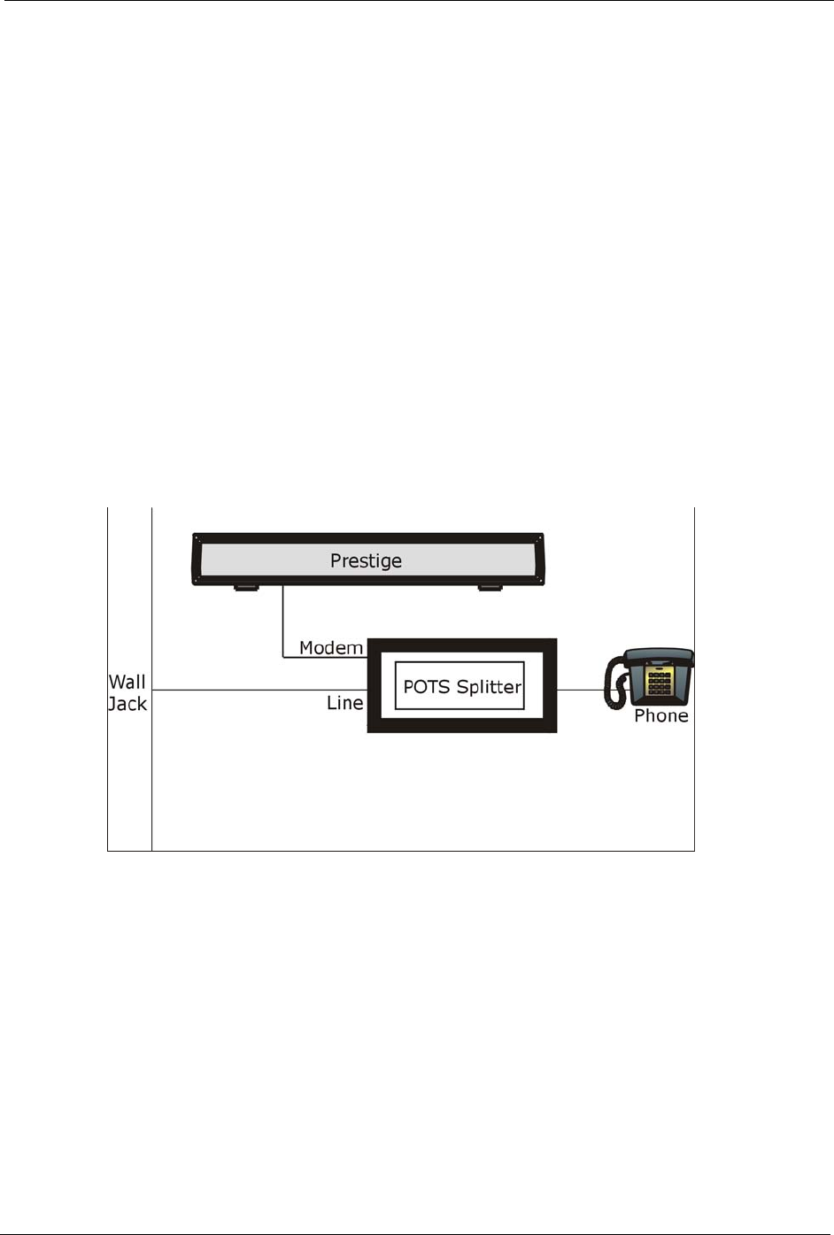
P-660H/HW/W-T Series User’ Guide
Appendix I 398
Appendix I
Splitters and Microfilters
This appendix tells you how to install a POTS splitter or a telephone microfilter.
Connecting a POTS Splitter
When you use the Full Rate (G.dmt) ADSL standard, you can use a POTS (Plain Old
Telephone Service) splitter to separate the telephone and ADSL signals. This allows
simultaneous Internet access and telephone service on the same line. A splitter also eliminates
the destructive interference conditions caused by telephone sets.
Install the POTS splitter at the point where the telephone line enters your residence, as shown
in the following figure.
Figure 259 Connecting a POTS Splitter
1Connect the side labeled “Phone” to your telephone.
2Connect the side labeled “Modem” to your Prestige.
3Connect the side labeled “Line” to the telephone wall jack.
Telephone Microfilters
Telephone voice transmissions take place in the lower frequency range, 0 - 4KHz, while
ADSL transmissions take place in the higher bandwidth range, above 4KHz. A microfilter acts
as a low-pass filter, for your telephone, to ensure that ADSL transmissions do not interfere
with your telephone voice transmissions. The use of a telephone microfilter is optional.
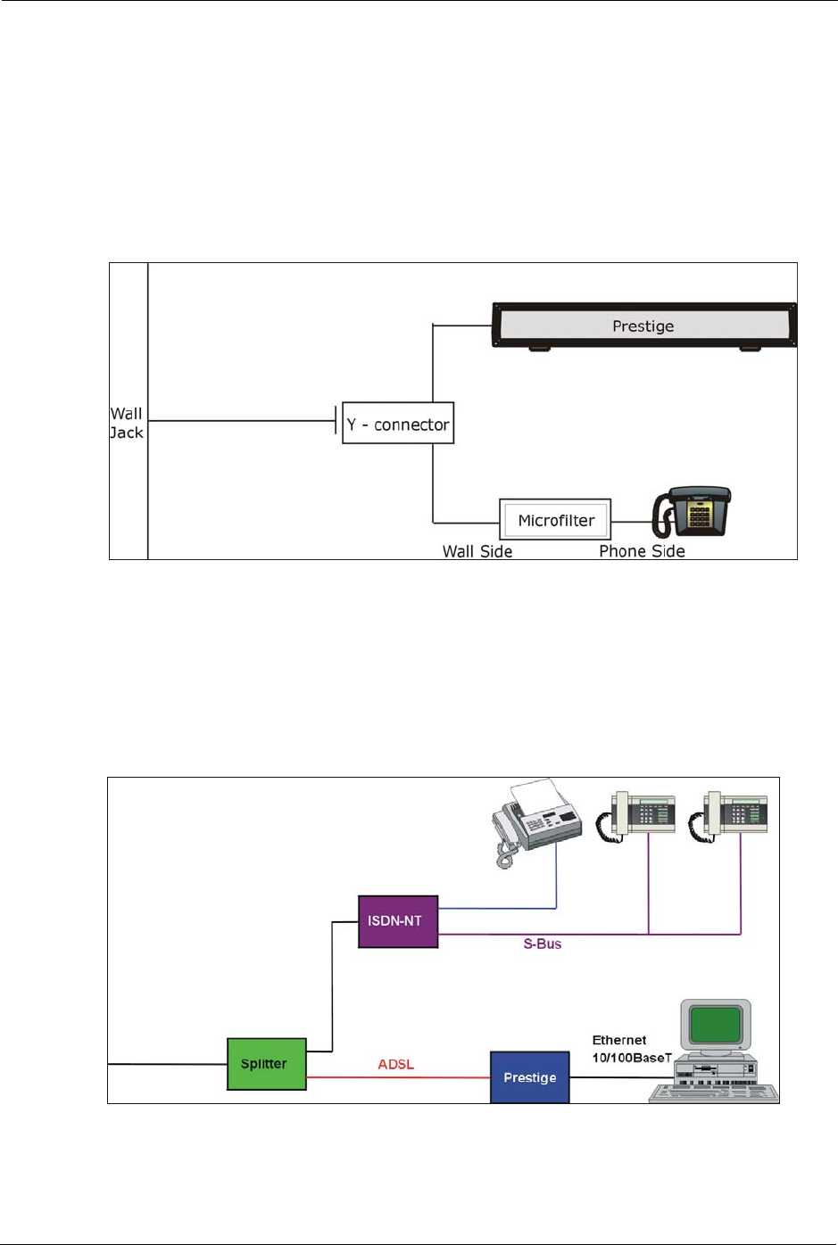
P-660H/HW/W-T Series User’ Guide
399 Appendix I
1Connect a phone cable from the wall jack to the single jack end of the Y- Connector.
2Connect a cable from the double jack end of the Y-Connector to the “wall side” of the
microfilter.
3Connect another cable from the double jack end of the Y-Connector to the Prestige.
4Connect the “phone side” of the microfilter to your telephone as shown in the following
figure.
Figure 260 Connecting a Microfilter
Prestige With ISDN
This section relates to people who use their Prestige with ADSL over ISDN (digital telephone
service) only. The following is an example installation for the Prestige with ISDN.
Figure 261 Prestige with ISDN

P-660H/HW/W-T Series User’ Guide
Appendix I 400

P-660H/HW/W-T Series User’ Guide
401 Appendix I

P-660H/HW/W-T Series User’ Guide
Appendix J 402
Appendix J
PPPoE
PPPoE in Action
An ADSL modem bridges a PPP session over Ethernet (PPP over Ethernet, RFC 2516) from
your computer to an ATM PVC (Permanent Virtual Circuit) which connects to a DSL Access
Concentrator where the PPP session terminates (see Figure 262 on page 403). One PVC can
support any number of PPP sessions from your LAN. PPPoE provides access control and
billing functionality in a manner similar to dial-up services using PPP.
Benefits of PPPoE
PPPoE offers the following benefits:
It provides you with a familiar dial-up networking (DUN) user interface.
It lessens the burden on the carriers of provisioning virtual circuits all the way to the ISP on
multiple switches for thousands of users. For GSTN (PSTN and ISDN), the switching fabric
is already in place.
It allows the ISP to use the existing dial-up model to authenticate and (optionally) to provide
differentiated services.
Traditional Dial-up Scenario
The following diagram depicts a typical hardware configuration where the computers use
traditional dial-up networking.
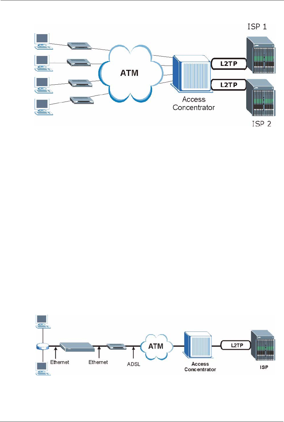
P-660H/HW/W-T Series User’ Guide
403 Appendix J
Figure 262 Single-Computer per Router Hardware Configuration
How PPPoE Works
The PPPoE driver makes the Ethernet appear as a serial link to the computer and the computer
runs PPP over it, while the modem bridges the Ethernet frames to the Access Concentrator
(AC). Between the AC and an ISP, the AC is acting as a L2TP (Layer 2 Tunneling Protocol)
LAC (L2TP Access Concentrator) and tunnels the PPP frames to the ISP. The L2TP tunnel is
capable of carrying multiple PPP sessions.
With PPPoE, the VC (Virtual Circuit) is equivalent to the dial-up connection and is between
the modem and the AC, as opposed to all the way to the ISP. However, the PPP negotiation is
between the computer and the ISP.
Prestige as a PPPoE Client
When using the Prestige as a PPPoE client, the computers on the LAN see only Ethernet and
are not aware of PPPoE. This alleviates the administrator from having to manage the PPPoE
clients on the individual computers.
Figure 263 Prestige as a PPPoE Client

P-660H/HW/W-T Series User’ Guide
Appendix K 404
Appendix K
Log Descriptions
This appendix provides descriptions of example log messages.
Table 140 System Maintenance Logs
LOG MESSAGE DESCRIPTION
Time calibration is
successful
The router has adjusted its time based on information from the
time server.
Time calibration failed The router failed to get information from the time server.
WAN interface gets IP:%s A WAN interface got a new IP address from the DHCP,
PPPoE, PPTP or dial-up server.
DHCP client IP expired A DHCP client's IP address has expired.
DHCP server assigns%s The DHCP server assigned an IP address to a client.
Successful SMT login Someone has logged on to the router's SMT interface.
SMT login failed Someone has failed to log on to the router's SMT interface.
Successful WEB login Someone has logged on to the router's web configurator
interface.
WEB login failed Someone has failed to log on to the router's web configurator
interface.
Successful TELNET login Someone has logged on to the router via telnet.
TELNET login failed Someone has failed to log on to the router via telnet.
Successful FTP login Someone has logged on to the router via ftp.
FTP login failed Someone has failed to log on to the router via ftp.
NAT Session Table is Full! The maximum number of NAT session table entries has been
exceeded and the table is full.
Starting Connectivity Monitor Starting Connectivity Monitor.
Time initialized by Daytime
Server
The router got the time and date from the Daytime server.
Time initialized by Time
server
The router got the time and date from the time server.
Time initialized by NTP
server
The router got the time and date from the NTP server.
Connect to Daytime server
fail
The router was not able to connect to the Daytime server.
Connect to Time server fail The router was not able to connect to the Time server.
Connect to NTP server fail The router was not able to connect to the NTP server.
Too large ICMP packet has
been dropped
The router dropped an ICMP packet that was too large.
SMT Session Begin An SMT management session has started.
SMT Session End An SMT management session has ended.

P-660H/HW/W-T Series User’ Guide
405 Appendix K
Configuration Change: PC =
0x%x, Task ID = 0x%x
The router is saving configuration changes.
Successful SSH login Someone has logged on to the router’s SSH server.
SSH login failed Someone has failed to log on to the router’s SSH server.
Successful HTTPS login Someone has logged on to the router's web configurator
interface using HTTPS protocol.
HTTPS login failed Someone has failed to log on to the router's web configurator
interface using HTTPS protocol.
Table 141 System Error Logs
LOG MESSAGE DESCRIPTION
%s exceeds the max.
number of session per
host!
This attempt to create a NAT session exceeds the maximum
number of NAT session table entries allowed to be created per
host.
setNetBIOSFilter: calloc
error
The router failed to allocate memory for the NetBIOS filter settings.
readNetBIOSFilter: calloc
error
The router failed to allocate memory for the NetBIOS filter settings.
WAN connection is down. A WAN connection is down. You cannot access the network
through this interface.
Table 142 Access Control Logs
LOG MESSAGE DESCRIPTION
Firewall default policy: [TCP |
UDP | IGMP | ESP | GRE | OSPF]
<Packet Direction>
Attempted TCP/UDP/IGMP/ESP/GRE/OSPF access
matched the default policy and was blocked or forwarded
according to the default policy’s setting.
Firewall rule [NOT] match:[TCP |
UDP | IGMP | ESP | GRE | OSPF]
<Packet Direction>, <rule:%d>
Attempted TCP/UDP/IGMP/ESP/GRE/OSPF access
matched (or did not match) a configured firewall rule
(denoted by its number) and was blocked or forwarded
according to the rule.
Triangle route packet forwarded:
[TCP | UDP | IGMP | ESP | GRE |
OSPF]
The firewall allowed a triangle route session to pass
through.
Packet without a NAT table entry
blocked: [TCP | UDP | IGMP | ESP
| GRE | OSPF]
The router blocked a packet that didn't have a
corresponding NAT table entry.
Router sent blocked web site
message: TCP
The router sent a message to notify a user that the router
blocked access to a web site that the user requested.
Table 140 System Maintenance Logs (continued)
LOG MESSAGE DESCRIPTION

P-660H/HW/W-T Series User’ Guide
Appendix K 406
Table 143 TCP Reset Logs
LOG MESSAGE DESCRIPTION
Under SYN flood attack,
sent TCP RST
The router sent a TCP reset packet when a host was under a SYN
flood attack (the TCP incomplete count is per destination host.)
Exceed TCP MAX
incomplete, sent TCP RST
The router sent a TCP reset packet when the number of TCP
incomplete connections exceeded the user configured threshold.
(the TCP incomplete count is per destination host.) Note: Refer to
TCP Maximum Incomplete in the Firewall Attack Alerts screen.
Peer TCP state out of
order, sent TCP RST
The router sent a TCP reset packet when a TCP connection state
was out of order.Note: The firewall refers to RFC793 Figure 6 to
check the TCP state.
Firewall session time
out, sent TCP RST
The router sent a TCP reset packet when a dynamic firewall
session timed out.
The default timeout values are as follows:
ICMP idle timeout: 3 minutes
UDP idle timeout: 3 minutes
TCP connection (three way handshaking) timeout: 270 seconds
TCP FIN-wait timeout: 2 MSL (Maximum Segment Lifetime set in
the TCP header).
TCP idle (established) timeout (s): 150 minutes
TCP reset timeout: 10 seconds
Exceed MAX incomplete,
sent TCP RST
The router sent a TCP reset packet when the number of
incomplete connections (TCP and UDP) exceeded the user-
configured threshold. (Incomplete count is for all TCP and UDP
connections through the firewall.)Note: When the number of
incomplete connections (TCP + UDP) > “Maximum Incomplete
High”, the router sends TCP RST packets for TCP connections
and destroys TOS (firewall dynamic sessions) until incomplete
connections < “Maximum Incomplete Low”.
Access block, sent TCP
RST
The router sends a TCP RST packet and generates this log if you
turn on the firewall TCP reset mechanism (via CI command: "sys
firewall tcprst").
Table 144 Packet Filter Logs
LOG MESSAGE DESCRIPTION
[TCP | UDP | ICMP | IGMP |
Generic] packet filter
matched (set:%d, rule:%d)
Attempted access matched a configured filter rule (denoted by
its set and rule number) and was blocked or forwarded
according to the rule.

P-660H/HW/W-T Series User’ Guide
407 Appendix K
Table 145 ICMP Logs
LOG MESSAGE DESCRIPTION
Firewall default policy: ICMP
<Packet Direction>, <type:%d>,
<code:%d>
ICMP access matched the default policy and was blocked
or forwarded according to the user's setting. For type and
code details, see Table 157 on page 416.
Firewall rule [NOT] match: ICMP
<Packet Direction>, <rule:%d>,
<type:%d>, <code:%d>
ICMP access matched (or didn’t match) a firewall rule
(denoted by its number) and was blocked or forwarded
according to the rule. For type and code details, see
Table 157 on page 416.
Triangle route packet forwarded:
ICMP
The firewall allowed a triangle route session to pass
through.
Packet without a NAT table entry
blocked: ICMP
The router blocked a packet that didn’t have a
corresponding NAT table entry.
Unsupported/out-of-order ICMP:
ICMP
The firewall does not support this kind of ICMP packets or
the ICMP packets are out of order.
Router reply ICMP packet: ICMP The router sent an ICMP reply packet to the sender.
Table 146 CDR Logs
LOG MESSAGE DESCRIPTION
board%d line%d channel%d,
call%d,%s C01 Outgoing Call
dev=%x ch=%x%s
The router received the setup requirements for a call. “call” is
the reference (count) number of the call. “dev” is the device
type (3 is for dial-up, 6 is for PPPoE, 10 is for PPTP).
"channel" or “ch” is the call channel ID.For example,"board 0
line 0 channel 0, call 3, C01 Outgoing Call dev=6 ch=0
"Means the router has dialed to the PPPoE server 3 times.
board%d line%d channel%d,
call%d,%s C02 OutCall
Connected%d%s
The PPPoE, PPTP or dial-up call is connected.
board%d line%d channel%d,
call%d,%s C02 Call Terminated
The PPPoE, PPTP or dial-up call was disconnected.
Table 147 PPP Logs
LOG MESSAGE DESCRIPTION
ppp:LCP Starting The PPP connection’s Link Control Protocol stage has started.
ppp:LCP Opening The PPP connection’s Link Control Protocol stage is opening.
ppp:CHAP Opening The PPP connection’s Challenge Handshake Authentication Protocol stage is
opening.
ppp:IPCP Starting The PPP connection’s Internet Protocol Control Protocol stage is starting.
ppp:IPCP Opening The PPP connection’s Internet Protocol Control Protocol stage is opening.

P-660H/HW/W-T Series User’ Guide
Appendix K 408
ppp:LCP Closing The PPP connection’s Link Control Protocol stage is closing.
ppp:IPCP Closing The PPP connection’s Internet Protocol Control Protocol stage is closing.
Table 148 UPnP Logs
LOG MESSAGE DESCRIPTION
UPnP pass through Firewall UPnP packets can pass through the firewall.
Table 149 Content Filtering Logs
LOG MESSAGE DESCRIPTION
%s: Keyword blocking The content of a requested web page matched a user defined keyword.
%s: Not in trusted web
list
The web site is not in a trusted domain, and the router blocks all traffic
except trusted domain sites.
%s: Forbidden Web site The web site is in the forbidden web site list.
%s: Contains ActiveX The web site contains ActiveX.
%s: Contains Java
applet
The web site contains a Java applet.
%s: Contains cookie The web site contains a cookie.
%s: Proxy mode
detected
The router detected proxy mode in the packet.
%s The content filter server responded that the web site is in the blocked
category list, but it did not return the category type.
%s:%s The content filter server responded that the web site is in the blocked
category list, and returned the category type.
%s(cache hit) The system detected that the web site is in the blocked list from the
local cache, but does not know the category type.
%s:%s(cache hit) The system detected that the web site is in blocked list from the local
cache, and knows the category type.
%s: Trusted Web site The web site is in a trusted domain.
%s When the content filter is not on according to the time schedule or you
didn't select the "Block Matched Web Site” check box, the system
forwards the web content.
Waiting content filter
server timeout
The external content filtering server did not respond within the timeout
period.
DNS resolving failed The Prestige cannot get the IP address of the external content filtering
via DNS query.
Creating socket failed The Prestige cannot issue a query because TCP/IP socket creation
failed, port:port number.
Table 147 PPP Logs (continued)
LOG MESSAGE DESCRIPTION

P-660H/HW/W-T Series User’ Guide
409 Appendix K
Connecting to content
filter server fail
The connection to the external content filtering server failed.
License key is invalid The external content filtering license key is invalid.
Table 150 Attack Logs
LOG MESSAGE DESCRIPTION
attack [TCP | UDP | IGMP |
ESP | GRE | OSPF]
The firewall detected a TCP/UDP/IGMP/ESP/GRE/OSPF attack.
attack ICMP (type:%d,
code:%d)
The firewall detected an ICMP attack. For type and code details,
see Table 157 on page 416.
land [TCP | UDP | IGMP |
ESP | GRE | OSPF]
The firewall detected a TCP/UDP/IGMP/ESP/GRE/OSPF land
attack.
land ICMP (type:%d,
code:%d)
The firewall detected an ICMP land attack. For type and code
details, see Table 157 on page 416.
ip spoofing - WAN [TCP |
UDP | IGMP | ESP | GRE |
OSPF]
The firewall detected an IP spoofing attack on the WAN port.
ip spoofing - WAN ICMP
(type:%d, code:%d)
The firewall detected an ICMP IP spoofing attack on the WAN port.
For type and code details, see Table 157 on page 416.
icmp echo: ICMP (type:%d,
code:%d)
The firewall detected an ICMP echo attack. For type and code
details, see Table 157 on page 416.
syn flood TCP The firewall detected a TCP syn flood attack.
ports scan TCP The firewall detected a TCP port scan attack.
teardrop TCP The firewall detected a TCP teardrop attack.
teardrop UDP The firewall detected an UDP teardrop attack.
teardrop ICMP (type:%d,
code:%d)
The firewall detected an ICMP teardrop attack. For type and code
details, see Table 157 on page 416.
illegal command TCP The firewall detected a TCP illegal command attack.
NetBIOS TCP The firewall detected a TCP NetBIOS attack.
ip spoofing - no routing
entry [TCP | UDP | IGMP |
ESP | GRE | OSPF]
The firewall classified a packet with no source routing entry as an
IP spoofing attack.
ip spoofing - no routing
entry ICMP (type:%d,
code:%d)
The firewall classified an ICMP packet with no source routing entry
as an IP spoofing attack.
vulnerability ICMP
(type:%d, code:%d)
The firewall detected an ICMP vulnerability attack. For type and
code details, see Table 157 on page 416.
traceroute ICMP (type:%d,
code:%d)
The firewall detected an ICMP traceroute attack. For type and
code details, see Table 157 on page 416.
Table 149 Content Filtering Logs (continued)
LOG MESSAGE DESCRIPTION

P-660H/HW/W-T Series User’ Guide
Appendix K 410
Table 151 IPSec Logs
LOG MESSAGE DESCRIPTION
Discard REPLAY packet The router received and discarded a packet with an incorrect
sequence number.
Inbound packet
authentication failed
The router received a packet that has been altered. A third party may
have altered or tampered with the packet.
Receive IPSec packet,
but no corresponding
tunnel exists
The router dropped an inbound packet for which SPI could not find a
corresponding phase 2 SA.
Rule <%d> idle time out,
disconnect
The router dropped a connection that had outbound traffic and no
inbound traffic for a certain time period. You can use the "ipsec timer
chk_conn" CI command to set the time period. The default value is 2
minutes.
WAN IP changed to <IP> The router dropped all connections with the “MyIP” configured as
“0.0.0.0” when the WAN IP address changed.
Table 152 IKE Logs
LOG MESSAGE DESCRIPTION
Active connection allowed
exceeded
The IKE process for a new connection failed because the limit
of simultaneous phase 2 SAs has been reached.
Start Phase 2: Quick Mode Phase 2 Quick Mode has started.
Verifying Remote ID failed: The connection failed during IKE phase 2 because the router
and the peer’s Local/Remote Addresses don’t match.
Verifying Local ID failed: The connection failed during IKE phase 2 because the router
and the peer’s Local/Remote Addresses don’t match.
IKE Packet Retransmit The router retransmitted the last packet sent because there
was no response from the peer.
Failed to send IKE Packet An Ethernet error stopped the router from sending IKE
packets.
Too many errors! Deleting SA An SA was deleted because there were too many errors.
Phase 1 IKE SA process done The phase 1 IKE SA process has been completed.
Duplicate requests with the
same cookie
The router received multiple requests from the same peer
while still processing the first IKE packet from the peer.
IKE Negotiation is in process The router has already started negotiating with the peer for
the connection, but the IKE process has not finished yet.
No proposal chosen Phase 1 or phase 2 parameters don’t match. Please check all
protocols / settings. Ex. One device being configured for
3DES and the other being configured for DES causes the
connection to fail.
Local / remote IPs of
incoming request conflict
with rule <%d>
The security gateway is set to “0.0.0.0” and the router used
the peer’s “Local Address” as the router’s “Remote Address”.
This information conflicted with static rule #d; thus the
connection is not allowed.

P-660H/HW/W-T Series User’ Guide
411 Appendix K
Cannot resolve Secure Gateway
Addr for rule <%d>
The router couldn’t resolve the IP address from the domain
name that was used for the secure gateway address.
Peer ID: <peer id> <My remote
type> -<My local type>
The displayed ID information did not match between the two
ends of the connection.
vs. My Remote <My remote> -
<My remote>
The displayed ID information did not match between the two
ends of the connection.
vs. My Local <My local>-<My
local>
The displayed ID information did not match between the two
ends of the connection.
Send <packet> A packet was sent.
Recv <packet> IKE uses ISAKMP to transmit data. Each ISAKMP packet
contains many different types of payloads. All of them show in
the LOG. Refer to RFC2408 – ISAKMP for a list of all ISAKMP
payload types.
Recv <Main or Aggressive>
Mode request from <IP>
The router received an IKE negotiation request from the peer
address specified.
Send <Main or Aggressive>
Mode request to <IP>
The router started negotiation with the peer.
Invalid IP <Peer local> /
<Peer local>
The peer’s “Local IP Address” is invalid.
Remote IP <Remote IP> /
<Remote IP> conflicts
The security gateway is set to “0.0.0.0” and the router used
the peer’s “Local Address” as the router’s “Remote Address”.
This information conflicted with static rule #d; thus the
connection is not allowed.
Phase 1 ID type mismatch This router’s "Peer ID Type" is different from the peer IPSec
router's "Local ID Type".
Phase 1 ID content mismatch This router’s "Peer ID Content" is different from the peer
IPSec router's "Local ID Content".
No known phase 1 ID type
found
The router could not find a known phase 1 ID in the
connection attempt.
ID type mismatch. Local /
Peer: <Local ID type/Peer ID
type>
The phase 1 ID types do not match.
ID content mismatch The phase 1 ID contents do not match.
Configured Peer ID Content:
<Configured Peer ID Content>
The phase 1 ID contents do not match and the configured
"Peer ID Content" is displayed.
Incoming ID Content:
<Incoming Peer ID Content>
The phase 1 ID contents do not match and the incoming
packet's ID content is displayed.
Unsupported local ID Type:
<%d>
The phase 1 ID type is not supported by the router.
Build Phase 1 ID The router has started to build the phase 1 ID.
Adjust TCP MSS to%d The router automatically changed the TCP Maximum
Segment Size value after establishing a tunnel.
Rule <%d> input idle time
out, disconnect
The tunnel for the listed rule was dropped because there was
no inbound traffic within the idle timeout period.
XAUTH succeed! Username:
<Username>
The router used extended authentication to authenticate the
listed username.
Table 152 IKE Logs (continued)
LOG MESSAGE DESCRIPTION

P-660H/HW/W-T Series User’ Guide
Appendix K 412
XAUTH fail! Username:
<Username>
The router was not able to use extended authentication to
authenticate the listed username.
Rule[%d] Phase 1 negotiation
mode mismatch
The listed rule’s IKE phase 1 negotiation mode did not match
between the router and the peer.
Rule [%d] Phase 1 encryption
algorithm mismatch
The listed rule’s IKE phase 1 encryption algorithm did not
match between the router and the peer.
Rule [%d] Phase 1
authentication algorithm
mismatch
The listed rule’s IKE phase 1 authentication algorithm did not
match between the router and the peer.
Rule [%d] Phase 1
authentication method
mismatch
The listed rule’s IKE phase 1 authentication method did not
match between the router and the peer.
Rule [%d] Phase 1 key group
mismatch
The listed rule’s IKE phase 1 key group did not match
between the router and the peer.
Rule [%d] Phase 2 protocol
mismatch
The listed rule’s IKE phase 2 protocol did not match between
the router and the peer.
Rule [%d] Phase 2 encryption
algorithm mismatch
The listed rule’s IKE phase 2 encryption algorithm did not
match between the router and the peer.
Rule [%d] Phase 2
authentication algorithm
mismatch
The listed rule’s IKE phase 2 authentication algorithm did not
match between the router and the peer.
Rule [%d] Phase 2
encapsulation mismatch
The listed rule’s IKE phase 2 encapsulation did not match
between the router and the peer.
Rule [%d]> Phase 2 pfs
mismatch
The listed rule’s IKE phase 2 perfect forward secret (pfs)
setting did not match between the router and the peer.
Rule [%d] Phase 1 ID mismatch The listed rule’s IKE phase 1 ID did not match between the
router and the peer.
Rule [%d] Phase 1 hash
mismatch
The listed rule’s IKE phase 1 hash did not match between the
router and the peer.
Rule [%d] Phase 1 preshared
key mismatch
The listed rule’s IKE phase 1 pre-shared key did not match
between the router and the peer.
Rule [%d] Tunnel built
successfully
The listed rule’s IPSec tunnel has been built successfully.
Rule [%d] Peer's public key
not found
The listed rule’s IKE phase 1 peer’s public key was not found.
Rule [%d] Verify peer's
signature failed
The listed rule’s IKE phase 1verification of the peer’s
signature failed.
Rule [%d] Sending IKE request IKE sent an IKE request for the listed rule.
Rule [%d] Receiving IKE
request
IKE received an IKE request for the listed rule.
Swap rule to rule [%d] The router changed to using the listed rule.
Rule [%d] Phase 1 key length
mismatch
The listed rule’s IKE phase 1 key length (with the AES
encryption algorithm) did not match between the router and
the peer.
Rule [%d] phase 1 mismatch The listed rule’s IKE phase 1 did not match between the router
and the peer.
Table 152 IKE Logs (continued)
LOG MESSAGE DESCRIPTION

P-660H/HW/W-T Series User’ Guide
413 Appendix K
Rule [%d] phase 2 mismatch The listed rule’s IKE phase 2 did not match between the router
and the peer.
Rule [%d] Phase 2 key length
mismatch
The listed rule’s IKE phase 2 key lengths (with the AES
encryption algorithm) did not match between the router and
the peer.
Table 153 PKI Logs
LOG MESSAGE DESCRIPTION
Enrollment successful The SCEP online certificate enrollment was successful. The
Destination field records the certification authority server IP address
and port.
Enrollment failed The SCEP online certificate enrollment failed. The Destination field
records the certification authority server’s IP address and port.
Failed to resolve
<SCEP CA server url>
The SCEP online certificate enrollment failed because the certification
authority server’s address cannot be resolved.
Enrollment successful The CMP online certificate enrollment was successful. The Destination
field records the certification authority server’s IP address and port.
Enrollment failed The CMP online certificate enrollment failed. The Destination field
records the certification authority server’s IP address and port.
Failed to resolve <CMP
CA server url>
The CMP online certificate enrollment failed because the certification
authority server’s IP address cannot be resolved.
Rcvd ca cert: <subject
name>
The router received a certification authority certificate, with subject
name as recorded, from the LDAP server whose IP address and port
are recorded in the Source field.
Rcvd user cert:
<subject name>
The router received a user certificate, with subject name as recorded,
from the LDAP server whose IP address and port are recorded in the
Source field.
Rcvd CRL <size>:
<issuer name>
The router received a CRL (Certificate Revocation List), with size and
issuer name as recorded, from the LDAP server whose IP address and
port are recorded in the Source field.
Rcvd ARL <size>:
<issuer name>
The router received an ARL (Authority Revocation List), with size and
issuer name as recorded, from the LDAP server whose address and
port are recorded in the Source field.
Failed to decode the
received ca cert
The router received a corrupted certification authority certificate from
the LDAP server whose address and port are recorded in the Source
field.
Failed to decode the
received user cert
The router received a corrupted user certificate from the LDAP server
whose address and port are recorded in the Source field.
Failed to decode the
received CRL
The router received a corrupted CRL (Certificate Revocation List) from
the LDAP server whose address and port are recorded in the Source
field.
Failed to decode the
received ARL
The router received a corrupted ARL (Authority Revocation List) from
the LDAP server whose address and port are recorded in the Source
field.
Table 152 IKE Logs (continued)
LOG MESSAGE DESCRIPTION

P-660H/HW/W-T Series User’ Guide
Appendix K 414
Rcvd data <size> too
large! Max size
allowed: <max size>
The router received directory data that was too large (the size is listed)
from the LDAP server whose address and port are recorded in the
Source field. The maximum size of directory data that the router allows
is also recorded.
Cert trusted: <subject
name>
The router has verified the path of the certificate with the listed subject
name.
Due to <reason codes>,
cert not trusted:
<subject name>
Due to the reasons listed, the certificate with the listed subject name
has not passed the path verification. The recorded reason codes are
only approximate reasons for not trusting the certificate. Please see
Table 154 on page 414 for the corresponding descriptions of the
codes.
Table 154 Certificate Path Verification Failure Reason Codes
CODE DESCRIPTION
1Algorithm mismatch between the certificate and the search constraints.
2Key usage mismatch between the certificate and the search constraints.
3Certificate was not valid in the time interval.
4(Not used)
5Certificate is not valid.
6Certificate signature was not verified correctly.
7Certificate was revoked by a CRL.
8Certificate was not added to the cache.
9Certificate decoding failed.
10 Certificate was not found (anywhere).
11 Certificate chain looped (did not find trusted root).
12 Certificate contains critical extension that was not handled.
13 Certificate issuer was not valid (CA specific information missing).
14 (Not used)
15 CRL is too old.
16 CRL is not valid.
17 CRL signature was not verified correctly.
18 CRL was not found (anywhere).
19 CRL was not added to the cache.
20 CRL decoding failed.
21 CRL is not currently valid, but in the future.
22 CRL contains duplicate serial numbers.
23 Time interval is not continuous.
24 Time information not available.
25 Database method failed due to timeout.
Table 153 PKI Logs (continued)
LOG MESSAGE DESCRIPTION

P-660H/HW/W-T Series User’ Guide
415 Appendix K
26 Database method failed.
27 Path was not verified.
28 Maximum path length reached.
Table 155 802.1X Logs
LOG MESSAGE DESCRIPTION
Local User Database accepts
user.
A user was authenticated by the local user database.
Local User Database reports user
credential error.
A user was not authenticated by the local user database
because of an incorrect user password.
Local User Database does not
find user`s credential.
A user was not authenticated by the local user database
because the user is not listed in the local user database.
RADIUS accepts user. A user was authenticated by the RADIUS Server.
RADIUS rejects user. Pls check
RADIUS Server.
A user was not authenticated by the RADIUS Server.
Please check the RADIUS Server.
Local User Database does not
support authentication method.
The local user database only supports the EAP-MD5
method. A user tried to use another authentication
method and was not authenticated.
User logout because of session
timeout expired.
The router logged out a user whose session expired.
User logout because of user
deassociation.
The router logged out a user who ended the session.
User logout because of no
authentication response from
user.
The router logged out a user from which there was no
authentication response.
User logout because of idle
timeout expired.
The router logged out a user whose idle timeout period
expired.
User logout because of user
request.
A user logged out.
Local User Database does not
support authentication mothed.
A user tried to use an authentication method that the local
user database does not support (it only supports EAP-
MD5).
No response from RADIUS. Pls
check RADIUS Server.
There is no response message from the RADIUS server,
please check the RADIUS server.
Use Local User Database to
authenticate user.
The local user database is operating as the
authentication server.
Use RADIUS to authenticate user. The RADIUS server is operating as the authentication
server.
No Server to authenticate user. There is no authentication server to authenticate a user.
Local User Database does not
find user`s credential.
A user was not authenticated by the local user database
because the user is not listed in the local user database.
Table 154 Certificate Path Verification Failure Reason Codes (continued)
CODE DESCRIPTION

P-660H/HW/W-T Series User’ Guide
Appendix K 416
Table 156 ACL Setting Notes
PACKET DIRECTION DIRECTION DESCRIPTION
(L to W) LAN to WAN ACL set for packets traveling from the LAN to the WAN.
(W to L) WAN to LAN ACL set for packets traveling from the WAN to the LAN.
(D to L) DMZ to LAN ACL set for packets traveling from the DMZ to the LAN.
(D to W) DMZ to WAN ACL set for packets traveling from the DMZ to the WAN.
(W to D) WAN to DMZ ACL set for packets traveling from the WAN to the DMZ.
(L to D) LAN to DMZ ACL set for packets traveling from the LAN to the DMZ.
(L to L/ZW) LAN to LAN/
Prestige
ACL set for packets traveling from the LAN to the LAN or
the Prestige.
(W to W/ZW) WAN to WAN/
Prestige
ACL set for packets traveling from the WAN to the WAN
or the Prestige.
(D to D/ZW) DMZ to DMZ/
Prestige
ACL set for packets traveling from the DMZ to the DM or
the Prestige.
Table 157 ICMP Notes
TYPE CODE DESCRIPTION
0Echo Reply
0Echo reply message
3Destination Unreachable
0Net unreachable
1Host unreachable
2Protocol unreachable
3Port unreachable
4A packet that needed fragmentation was dropped because it was set to Don't
Fragment (DF)
5Source route failed
4Source Quench
0A gateway may discard internet datagrams if it does not have the buffer space
needed to queue the datagrams for output to the next network on the route to
the destination network.
5Redirect
0Redirect datagrams for the Network
1Redirect datagrams for the Host
2Redirect datagrams for the Type of Service and Network
3Redirect datagrams for the Type of Service and Host
8Echo
0Echo message

P-660H/HW/W-T Series User’ Guide
417 Appendix K
The following table shows RFC-2408 ISAKMP payload types that the log displays. Please
refer to the RFC for detailed information on each type.
11 Time Exceeded
0Time to live exceeded in transit
1Fragment reassembly time exceeded
12 Parameter Problem
0Pointer indicates the error
13 Timestamp
0Timestamp request message
14 Timestamp Reply
0Timestamp reply message
15 Information Request
0Information request message
16 Information Reply
0Information reply message
Table 158 Syslog Logs
LOG MESSAGE DESCRIPTION
<Facility*8 + Severity>Mon dd
hr:mm:ss hostname
src="<srcIP:srcPort>"
dst="<dstIP:dstPort>"
msg="<msg>" note="<note>"
devID="<mac address last three
numbers>" cat="<category>
"This message is sent by the system ("RAS" displays as the
system name if you haven’t configured one) when the router
generates a syslog. The facility is defined in the web MAIN
MENU->LOGS->Log Settings page. The severity is the
log’s syslog class. The definition of messages and notes
are defined in the various log charts throughout this
appendix. The “devID” is the last three characters of the
MAC address of the router’s LAN port. The “cat” is the same
as the category in the router’s logs.
Table 159 RFC-2408 ISAKMP Payload Types
LOG DISPLAY PAYLOAD TYPE
SA Security Association
PROP Proposal
TRANS Transform
KE Key Exchange
ID Identification
CER Certificate
CER_REQ Certificate Request
HASH Hash
Table 157 ICMP Notes (continued)
TYPE CODE DESCRIPTION

P-660H/HW/W-T Series User’ Guide
Appendix K 418
Log Commands
Go to the command interpreter interface.
Configuring What You Want the Prestige to Log
1Use the sys logs load command to load the log setting buffer that allows you to configure
which logs the Prestige is to record.
2Use sys logs category to view a list of the log categories.
Figure 264 Displaying Log Categories Example
3Use sys logs category followed by a log category to display the parameters that are
available for the category.
Figure 265 Displaying Log Parameters Example
4Use sys logs category followed by a log category and a parameter to decide what to
record.
SIG Signature
NONCE Nonce
NOTFY Notification
DEL Delete
VID Vendor ID
Table 159 RFC-2408 ISAKMP Payload Types (continued)
LOG DISPLAY PAYLOAD TYPE
Copyright (c) 1994 - 2004 ZyXEL Communications Corp.
ras>?
Valid commands are:
sys exit ether aux
ip ipsec bridge bm
certificates cnm 8021x radius
ras>
ras> sys logs category access
Usage: [0:none/1:log/2:alert/3:both] [0:don't show debug type/
1:show debug type]

P-660H/HW/W-T Series User’ Guide
419 Appendix K
Use 0 to not record logs for that category, 1 to record only logs for that
category, 2 to record only alerts for that category, and 3 to record both
logs and alerts for that category. Not every parameter is available with
every category.
5Step 5.Use the sys logs save command to store the settings in the Prestige (you must do
this in order to record logs).
Displaying Logs
• Use the sys logs display command to show all of the logs in the Prestige’s log.
• Use the sys logs category display command to show the log settings for all of the log
categories.
• Use the sys logs display [log category] command to show the logs in an individual
Prestige log category.
• Use the sys logs clear command to erase all of the Prestige’s logs.
Log Command Example
This example shows how to set the Prestige to record the access logs and alerts and then view
the results.
ras> sys logs load
ras> sys logs category access 3
ras> sys logs save
ras> sys logs display access
#.time source destination notes
message
0|06/08/2004 05:58:21 |172.21.4.154 |224.0.1.24 |ACCESS
BLOCK
Firewall default policy: IGMP (W to W/ZW)
1|06/08/2004 05:58:20 |172.21.3.56 |239.255.255.250 |ACCESS
BLOCK
Firewall default policy: IGMP (W to W/ZW)
2|06/08/2004 05:58:20 |172.21.0.2 |239.255.255.254 |ACCESS
BLOCK
Firewall default policy: IGMP (W to W/ZW)
3|06/08/2004 05:58:20 |172.21.3.191 |224.0.1.22 |ACCESS
BLOCK
Firewall default policy: IGMP (W to W/ZW)
4|06/08/2004 05:58:20 |172.21.0.254 |224.0.0.1 |ACCESS
BLOCK
Firewall default policy: IGMP (W to W/ZW)
5|06/08/2004 05:58:20 |172.21.4.187:137 |172.21.255.255:137 |ACCESS
BLOCK
Firewall default policy: UDP (W to W/ZW)
P-660H/HW/W-T Series User’ Guide
Appendix L 420
Appendix L
Wireless LANs
Wireless LAN Topologies
This section discusses ad-hoc and infrastructure wireless LAN topologies.
Ad-hoc Wireless LAN Configuration
The simplest WLAN configuration is an independent (Ad-hoc) WLAN that connects a set of
computers with wireless stations (A, B, C). Any time two or more wireless adapters are within
range of each other, they can set up an independent network, which is commonly referred to as
an Ad-hoc network or Independent Basic Service Set (IBSS). The following diagram shows an
example of notebook computers using wireless adapters to form an Ad-hoc wireless LAN.
Figure 266 Peer-to-Peer Communication in an Ad-hoc Network
BSS
A Basic Service Set (BSS) exists when all communications between wireless stations or
between a wireless station and a wired network client go through one access point (AP).
Intra-BSS traffic is traffic between wireless stations in the BSS. When Intra-BSS is enabled,
wireless station A and B can access the wired network and communicate with each other.
When Intra-BSS is disabled, wireless station A and B can still access the wired network but
cannot communicate with each other.
P-660H/HW/W-T Series User’ Guide
421 Appendix L
Figure 267 Basic Service Set
ESS
An Extended Service Set (ESS) consists of a series of overlapping BSSs, each containing an
access point, with each access point connected together by a wired network. This wired
connection between APs is called a Distribution System (DS).
This type of wireless LAN topology is called an Infrastructure WLAN. The Access Points not
only provide communication with the wired network but also mediate wireless network traffic
in the immediate neighborhood.
An ESSID (ESS IDentification) uniquely identifies each ESS. All access points and their
associated wireless stations within the same ESS must have the same ESSID in order to
communicate.
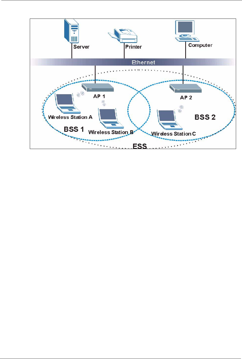
P-660H/HW/W-T Series User’ Guide
Appendix L 422
Figure 268 Infrastructure WLAN
Channel
A channel is the radio frequency(ies) used by IEEE 802.11a/b/g wireless devices. Channels
available depend on your geographical area. You may have a choice of channels (for your
region) so you should use a different channel than an adjacent AP (access point) to reduce
interference. Interference occurs when radio signals from different access points overlap
causing interference and degrading performance.
Adjacent channels partially overlap however. To avoid interference due to overlap, your AP
should be on a channel at least five channels away from a channel that an adjacent AP is using.
For example, if your region has 11 channels and an adjacent AP is using channel 1, then you
need to select a channel between 6 or 11.
RTS/CTS
A hidden node occurs when two stations are within range of the same access point, but are not
within range of each other. The following figure illustrates a hidden node. Both stations (STA)
are within range of the access point (AP) or wireless gateway, but out-of-range of each other,
so they cannot "hear" each other, that is they do not know if the channel is currently being
used. Therefore, they are considered hidden from each other.
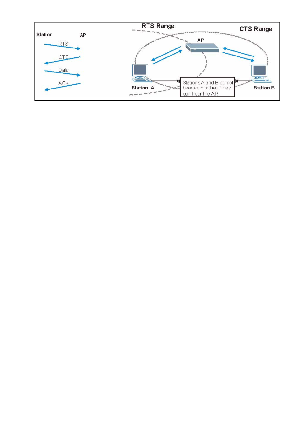
P-660H/HW/W-T Series User’ Guide
423 Appendix L
Figure 269 RTS/CTS
When station A sends data to the AP, it might not know that the station B is already using the
channel. If these two stations send data at the same time, collisions may occur when both sets
of data arrive at the AP at the same time, resulting in a loss of messages for both stations.
RTS/CTS is designed to prevent collisions due to hidden nodes. An RTS/CTS defines the
biggest size data frame you can send before an RTS (Request To Send)/CTS (Clear to Send)
handshake is invoked.
When a data frame exceeds the RTS/CTS value you set (between 0 to 2432 bytes), the station
that wants to transmit this frame must first send an RTS (Request To Send) message to the AP
for permission to send it. The AP then responds with a CTS (Clear to Send) message to all
other stations within its range to notify them to defer their transmission. It also reserves and
confirms with the requesting station the time frame for the requested transmission.
Stations can send frames smaller than the specified RTS/CTS directly to the AP without the
RTS (Request To Send)/CTS (Clear to Send) handshake.
You should only configure RTS/CTS if the possibility of hidden nodes exists on your network
and the "cost" of resending large frames is more than the extra network overhead involved in
the RTS (Request To Send)/CTS (Clear to Send) handshake.
If the RTS/CTS value is greater than the Fragmentation Threshold value (see next), then the
RTS (Request To Send)/CTS (Clear to Send) handshake will never occur as data frames will
be fragmented before they reach RTS/CTS size.
Note: Enabling the RTS Threshold causes redundant network overhead that could
negatively affect the throughput performance instead of providing a remedy.
Fragmentation Threshold
A Fragmentation Threshold is the maximum data fragment size (between 256 and 2432
bytes) that can be sent in the wireless network before the AP will fragment the packet into
smaller data frames.

P-660H/HW/W-T Series User’ Guide
Appendix L 424
A large Fragmentation Threshold is recommended for networks not prone to interference
while you should set a smaller threshold for busy networks or networks that are prone to
interference.
If the Fragmentation Threshold value is smaller than the RTS/CTS value (see previously)
you set then the RTS (Request To Send)/CTS (Clear to Send) handshake will never occur as
data frames will be fragmented before they reach RTS/CTS size.
Preamble Type
A preamble is used to synchronize the transmission timing in your wireless network. There are
two preamble modes: Long and Short.
Short preamble takes less time to process and minimizes overhead, so it should be used in a
good wireless network environment when all wireless stations support it.
Select Long if you have a ‘noisy’ network or are unsure of what preamble mode your wireless
stations support as all IEEE 802.11b compliant wireless adapters must support long preamble.
However, not all wireless adapters support short preamble. Use long preamble if you are
unsure what preamble mode the wireless adapters support, to ensure interpretability between
the AP and the wireless stations and to provide more reliable communication in ‘noisy’
networks.
Select Dynamic to have the AP automatically use short preamble when all wireless stations
support it, otherwise the AP uses long preamble.
Note: The AP and the wireless stations MUST use the same preamble mode in order
to communicate.
IEEE 802.11g Wireless LAN
IEEE 802.11g is fully compatible with the IEEE 802.11b standard. This means an IEEE
802.11b adapter can interface directly with an IEEE 802.11g access point (and vice versa) at
11 Mbps or lower depending on range. IEEE 802.11g has several intermediate rate steps
between the maximum and minimum data rates. The IEEE 802.11g data rate and modulation
are as follows:
Table 160 IEEE 802.11g
DATA RATE (MBPS) MODULATION
1 DBPSK (Differential Binary Phase Shift Keyed)
2 DQPSK (Differential Quadrature Phase Shift Keying)
5.5 / 11 CCK (Complementary Code Keying)
6/9/12/18/24/36/48/54 OFDM (Orthogonal Frequency Division Multiplexing)

P-660H/HW/W-T Series User’ Guide
425 Appendix L
IEEE 802.1x
In June 2001, the IEEE 802.1x standard was designed to extend the features of IEEE 802.11 to
support extended authentication as well as providing additional accounting and control
features. It is supported by Windows XP and a number of network devices. Some advantages
of IEEE 802.1x are:
• User based identification that allows for roaming.
• Support for RADIUS (Remote Authentication Dial In User Service, RFC 2138, 2139) for
centralized user profile and accounting management on a network RADIUS server.
• Support for EAP (Extensible Authentication Protocol, RFC 2486) that allows additional
authentication methods to be deployed with no changes to the access point or the wireless
stations.
RADIUS
RADIUS is based on a client-server model that supports authentication, authorization and
accounting. The access point is the client and the server is the RADIUS server. The RADIUS
server handles the following tasks:
• Authentication
Determines the identity of the users.
• Authorization
Determines the network services available to authenticated users once they are connected
to the network.
• Accounting
Keeps track of the client’s network activity.
RADIUS is a simple package exchange in which your AP acts as a message relay between the
wireless station and the network RADIUS server.
Types of RADIUS Messages
The following types of RADIUS messages are exchanged between the access point and the
RADIUS server for user authentication:
• Access-Request
Sent by an access point requesting authentication.
• Access-Reject
Sent by a RADIUS server rejecting access.
• Access-Accept
Sent by a RADIUS server allowing access.

P-660H/HW/W-T Series User’ Guide
Appendix L 426
• Access-Challenge
Sent by a RADIUS server requesting more information in order to allow access. The
access point sends a proper response from the user and then sends another Access-
Request message.
The following types of RADIUS messages are exchanged between the access point and the
RADIUS server for user accounting:
• Accounting-Request
Sent by the access point requesting accounting.
• Accounting-Response
Sent by the RADIUS server to indicate that it has started or stopped accounting.
In order to ensure network security, the access point and the RADIUS server use a shared
secret key, which is a password, they both know. The key is not sent over the network. In
addition to the shared key, password information exchanged is also encrypted to protect the
network from unauthorized access.
Types of Authentication
This appendix discusses some popular authentication types: EAP-MD5, EAP-TLS, EAP-
TTLS, PEAP and LEAP.
The type of authentication you use depends on the RADIUS server or the AP. Consult your
network administrator for more information.
EAP-MD5 (Message-Digest Algorithm 5)
MD5 authentication is the simplest one-way authentication method. The authentication server
sends a challenge to the wireless station. The wireless station ‘proves’ that it knows the
password by encrypting the password with the challenge and sends back the information.
Password is not sent in plain text.
However, MD5 authentication has some weaknesses. Since the authentication server needs to
get the plaintext passwords, the passwords must be stored. Thus someone other than the
authentication server may access the password file. In addition, it is possible to impersonate an
authentication server as MD5 authentication method does not perform mutual authentication.
Finally, MD5 authentication method does not support data encryption with dynamic session
key. You must configure WEP encryption keys for data encryption.

P-660H/HW/W-T Series User’ Guide
427 Appendix L
EAP-TLS (Transport Layer Security)
With EAP-TLS, digital certifications are needed by both the server and the wireless stations
for mutual authentication. The server presents a certificate to the client. After validating the
identity of the server, the client sends a different certificate to the server. The exchange of
certificates is done in the open before a secured tunnel is created. This makes user identity
vulnerable to passive attacks. A digital certificate is an electronic ID card that authenticates the
sender’s identity. However, to implement EAP-TLS, you need a Certificate Authority (CA) to
handle certificates, which imposes a management overhead.
EAP-TTLS (Tunneled Transport Layer Service)
EAP-TTLS is an extension of the EAP-TLS authentication that uses certificates for only the
server-side authentications to establish a secure connection. Client authentication is then done
by sending username and password through the secure connection, thus client identity is
protected. For client authentication, EAP-TTLS supports EAP methods and legacy
authentication methods such as PAP, CHAP, MS-CHAP and MS-CHAP v2.
PEAP (Protected EAP)
Like EAP-TTLS, server-side certificate authentication is used to establish a secure connection,
then use simple username and password methods through the secured connection to
authenticate the clients, thus hiding client identity. However, PEAP only supports EAP
methods, such as EAP-MD5, EAP-MSCHAPv2 and EAP-GTC (EAP-Generic Token Card),
for client authentication. EAP-GTC is implemented only by Cisco.
LEAP
LEAP (Lightweight Extensible Authentication Protocol) is a Cisco implementation of IEEE
802.1x.
Dynamic WEP Key Exchange
The AP maps a unique key that is generated with the RADIUS server. This key expires when
the wireless connection times out, disconnects or reauthentication times out. A new WEP key
is generated each time reauthentication is performed.
If this feature is enabled, it is not necessary to configure a default encryption key in the
Wireless screen. You may still configure and store keys here, but they will not be used while
Dynamic WEP is enabled.
Note: EAP-MD5 cannot be used with Dynamic WEP Key Exchange

P-660H/HW/W-T Series User’ Guide
Appendix L 428
For added security, certificate-based authentications (EAP-TLS, EAP-TTLS and PEAP) use
dynamic keys for data encryption. They are often deployed in corporate environments, but for
public deployment, a simple user name and password pair is more practical. The following
table is a comparison of the features of authentication types.
WPA
User Authentication
WPA applies IEEE 802.1x and Extensible Authentication Protocol (EAP) to authenticate
wireless stations using an external RADIUS database.
Encryption
WPA improves data encryption by using Temporal Key Integrity Protocol (TKIP) or
Advanced Encryption Standard (AES), Message Integrity Check (MIC) and IEEE 802.1x.
TKIP uses 128-bit keys that are dynamically generated and distributed by the authentication
server. It includes a per-packet key mixing function, a Message Integrity Check (MIC) named
Michael, an extended initialization vector (IV) with sequencing rules, and a re-keying
mechanism.
TKIP regularly changes and rotates the encryption keys so that the same encryption key is
never used twice.
The RADIUS server distributes a Pairwise Master Key (PMK) key to the AP that then sets up
a key hierarchy and management system, using the PMK to dynamically generate unique data
encryption keys to encrypt every data packet that is wirelessly communicated between the AP
and the wireless stations. This all happens in the background automatically.
AES (Advanced Encryption Standard) also uses a secret key. This implementation of AES
applies a 128-bit key to 128-bit blocks of data.
Table 161 Comparison of EAP Authentication Types
EAP-MD5 EAP-TLS EAP-TTLS PEAP LEAP
Mutual Authentication No Yes Yes Yes Yes
Certificate – Client No Yes Optional Optional No
Certificate – Server No Yes Yes Yes No
Dynamic Key Exchange No Yes Yes Yes Yes
Credential Integrity None Strong Strong Strong Moderate
Deployment Difficulty Easy Hard Moderate Moderate Moderate
Client Identity Protection No No Yes Yes No

P-660H/HW/W-T Series User’ Guide
429 Appendix L
The Message Integrity Check (MIC) is designed to prevent an attacker from capturing data
packets, altering them and resending them. The MIC provides a strong mathematical function
in which the receiver and the transmitter each compute and then compare the MIC. If they do
not match, it is assumed that the data has been tampered with and the packet is dropped.
By generating unique data encryption keys for every data packet and by creating an integrity
checking mechanism (MIC), TKIP makes it much more difficult to decrypt data on a Wi-Fi
network than WEP, making it difficult for an intruder to break into the network.
The encryption mechanisms used for WPA and WPA-PSK are the same. The only difference
between the two is that WPA-PSK uses a simple common password, instead of user-specific
credentials. The common-password approach makes WPA-PSK susceptible to brute-force
password-guessing attacks but it’s still an improvement over WEP as it employs an easier-to-
use, consistent, single, alphanumeric password.
Security Parameters Summary
Refer to this table to see what other security parameters you should configure for each
Authentication Method/ key management protocol type. MAC address filters are not
dependent on how you configure these security features.
Table 162 Wireless Security Relational Matrix
AUTHENTICATION
METHOD/ KEY
MANAGEMENT PROTOCOL
ENCRYPTION
METHOD
ENTER
MANUAL KEY ENABLE IEEE 802.1X
Open None No No
Open WEP No Enable with Dynamic WEP Key
Yes Enable without Dynamic WEP Key
Yes Disable
Shared WEP No Enable with Dynamic WEP Key
Yes Enable without Dynamic WEP Key
Yes Disable
WPA WEP No Yes
WPA TKIP No Yes
WPA-PSK WEP Yes Yes
WPA-PSK TKIP Yes Yes

P-660H/HW/W-T Series User’ Guide
Appendix M 430
APPENDIX M
Internal SPTGEN
Internal SPTGEN Overview
Internal SPTGEN (System Parameter Table Generator) is a configuration text file useful for
efficient configuration of multiple Prestiges. Internal SPTGEN lets you configure, save and
upload multiple menus at the same time using just one configuration text file – eliminating the
need to navigate and configure individual SMT menus for each Prestige.
The Configuration Text File Format
All Internal SPTGEN text files conform to the following format:
<field identification number = field name = parameter values
allowed = input>,
where <input> is your input conforming to <parameter values allowed>.
The figure shown next is an example of an Internal SPTGEN text file.
Figure 270 Configuration Text File Format: Column Descriptions
Note: DO NOT alter or delete any field except parameters in the Input column.
For more text file examples, refer to the Example Internal SPTGEN Screens Appendix.
Internal SPTGEN File Modification - Important Points to Remember
Each parameter you enter must be preceded by one “=”sign and one space.
/ Menu 1 General Setup
10000000 = Configured <0(No)| 1(Yes)> = 1
10000001 = System Name <Str> = Prestige
10000002 = Location <Str> =
10000003 = Contact Person’s Name <Str> =
10000004 = Route IP <0(No)| 1(Yes)> = 1
10000005 = Route IPX <0(No)| 1(Yes)> = 0
10000006 = Bridge <0(No)| 1(Yes)> = 0
P-660H/HW/W-T Series User’ Guide
431 Appendix M
Some parameters are dependent on others. For example, if you disable the Configured field in
menu 1 (see Figure 270 on page 430), then you disable every field in this menu.
If you enter a parameter that is invalid in the Input column, the Prestige will not save the
configuration and the command line will display the Field Identification Number. Figure
271 on page 431, shown next, is an example of what the Prestige displays if you enter a value
other than “0” or “1” in the Input column of Field Identification Number 1000000 (refer to
Figure 270 on page 430).
Figure 271 Invalid Parameter Entered: Command Line Example
The Prestige will display the following if you enter parameter(s) that are valid.
Figure 272 Valid Parameter Entered: Command Line Example
Internal SPTGEN FTP Download Example
1Launch your FTP application.
2Enter "bin". The command “bin” sets the transfer mode to binary.
3Get "rom-t" file. The command “get” transfers files from the Prestige to your computer.
The name “rom-t” is the configuration filename on the Prestige.
4Edit the "rom-t" file using a text editor (do not use a word processor). You must leave
this FTP screen to edit.
field value is not legal error:-1
ROM-t is not saved, error Line ID:10000000
reboot to get the original configuration
Bootbase Version: V2.02 | 2/22/2001 13:33:11
RAM: Size = 8192 Kbytes
FLASH: Intel 8M *2
Please wait for the system to write SPT text file(ROM-t)...
Bootbase Version: V2.02 | 2/22/2001 13:33:11
RAM: Size = 8192 Kbytes
FLASH: Intel 8M *2

P-660H/HW/W-T Series User’ Guide
Appendix M 432
Figure 273 Internal SPTGEN FTP Download Example
Note: You can rename your “rom-t” file when you save it to your computer but it must
be named “rom-t” when you upload it to your Prestige.
Internal SPTGEN FTP Upload Example
1Launch your FTP application.
2Enter "bin". The command “bin” sets the transfer mode to binary.
3Upload your “rom-t” file from your computer to the Prestige using the “put” command.
computer to the Prestige.
4Exit this FTP application.
Figure 274 Internal SPTGEN FTP Upload Example
Example Internal SPTGEN Screens
This section covers Prestige Internal SPTGEN screens.
c:\ftp 192.168.1.1
220 PPP FTP version 1.0 ready at Sat Jan 1 03:22:12 2000
User (192.168.1.1:(none)):
331 Enter PASS command
Password:
230 Logged in
ftp>bin
200 Type I OK
ftp> get rom-t
ftp>bye
c:\edit rom-t
(edit the rom-t text file by a text editor and save it)
c:\ftp 192.168.1.1
220 PPP FTP version 1.0 ready at Sat Jan 1 03:22:12 2000
User (192.168.1.1:(none)):
331 Enter PASS command
Password:
230 Logged in
ftp>bin
200 Type I OK
ftp> put rom-t
ftp>bye
Table 163 Abbreviations Used in the Example Internal SPTGEN Screens Table
ABBREVIATION MEANING
FIN Field Identification Number (not seen in SMT screens)
FN Field Name

P-660H/HW/W-T Series User’ Guide
433 Appendix M
The following are Internal SPTGEN screens associated with the SMT screens of your Prestige.
PVA Parameter Values Allowed
INPUT An example of what you may enter
* Applies to the Prestige.
Table 163 Abbreviations Used in the Example Internal SPTGEN Screens Table (continued)
ABBREVIATION MEANING
Table 164 Menu 1 General Setup (SMT Menu 1)
/ Menu 1 General Setup (SMT Menu 1)
FIN FN PVA INPUT
10000000 = Configured <0(No) | 1(Yes)> = 0
10000001 = System Name <Str> = Prestige
10000002 = Location <Str> =
10000003 = Contact Person's Name <Str> =
10000004 = Route IP <0(No) | 1(Yes)> = 1
10000006 = Bridge <0(No) | 1(Yes)> = 0
Table 165 Menu 3 (SMT Menu 3 )
/ Menu 3.1 General Ethernet Setup (SMT menu 3.1)
FIN FN PVA INPUT
30100001 = Input Protocol filters Set 1 = 2
30100002 = Input Protocol filters Set 2 = 256
30100003 = Input Protocol filters Set 3 = 256
30100004 = Input Protocol filters Set 4 = 256
30100005 = Input device filters Set 1 = 256
30100006 = Input device filters Set 2 = 256
30100007 = Input device filters Set 3 = 256
30100008 = Input device filters Set 4 = 256
30100009 = Output protocol filters Set 1 = 256
30100010 = Output protocol filters Set 2 = 256
30100011 = Output protocol filters Set 3 = 256
30100012 = Output protocol filters Set 4 = 256
30100013 = Output device filters Set 1 = 256
30100014 = Output device filters Set 2 = 256
30100015 = Output device filters Set 3 = 256
30100016 = Output device filters Set 4 = 256
/ Menu 3.2 TCP/IP and DHCP Ethernet Setup (SMT Menu 3.2)

P-660H/HW/W-T Series User’ Guide
Appendix M 434
FIN FN PVA INPUT
30200001 = DHCP <0(None) |
1(Server) |
2(Relay)>
= 0
30200002 = Client IP Pool Starting Address =
192.168.1.33
30200003 = Size of Client IP Pool = 32
30200004 = Primary DNS Server = 0.0.0.0
30200005 = Secondary DNS Server = 0.0.0.0
30200006 = Remote DHCP Server = 0.0.0.0
30200008 = IP Address =
172.21.2.200
30200009 = IP Subnet Mask = 16
30200010 = RIP Direction <0(None) |
1(Both) | 2(In
Only) | 3(Out
Only)>
= 0
30200011 = Version <0(Rip-1) |
1(Rip-2B)
|2(Rip-2M)>
= 0
30200012 = Multicast <0(IGMP-v2) |
1(IGMP-v1) |
2(None)>
= 2
30200013 = IP Policies Set 1 (1~12) = 256
30200014 = IP Policies Set 2 (1~12) = 256
30200015 = IP Policies Set 3 (1~12) = 256
30200016 = IP Policies Set 4 (1~12) = 256
/ Menu 3.2.1 IP Alias Setup (SMT Menu 3.2.1)
FIN FN PVA INPUT
30201001 = IP Alias 1 <0(No) |
1(Yes)>
= 0
30201002 = IP Address = 0.0.0.0
30201003 = IP Subnet Mask = 0
30201004 = RIP Direction <0(None) |
1(Both) | 2(In
Only) | 3(Out
Only)>
= 0
30201005 = Version <0(Rip-1) |
1(Rip-2B)
|2(Rip-2M)>
= 0
30201006 = IP Alias #1 Incoming protocol filters
Set 1
= 256
30201007 = IP Alias #1 Incoming protocol filters
Set 2
= 256
Table 165 Menu 3 (SMT Menu 3 (continued))

P-660H/HW/W-T Series User’ Guide
435 Appendix M
30201008 = IP Alias #1 Incoming protocol filters
Set 3
= 256
30201009 = IP Alias #1 Incoming protocol filters
Set 4
= 256
30201010 = IP Alias #1 Outgoing protocol filters
Set 1
= 256
30201011 = IP Alias #1 Outgoing protocol filters
Set 2
= 256
30201012 = IP Alias #1 Outgoing protocol filters
Set 3
= 256
30201013 = IP Alias #1 Outgoing protocol filters
Set 4
= 256
30201014 = IP Alias 2 <0(No) | 1(Yes)> = 0
30201015 = IP Address = 0.0.0.0
30201016 = IP Subnet Mask = 0
30201017 = RIP Direction <0(None) |
1(Both) | 2(In
Only) | 3(Out
Only)>
= 0
30201018 = Version <0(Rip-1) |
1(Rip-2B)
|2(Rip-2M)>
= 0
30201019 = IP Alias #2 Incoming protocol filters
Set 1
= 256
30201020 = IP Alias #2 Incoming protocol filters
Set 2
= 256
30201021 = IP Alias #2 Incoming protocol filters
Set 3
= 256
30201022 = IP Alias #2 Incoming protocol filters
Set 4
= 256
30201023 = IP Alias #2 Outgoing protocol filters
Set 1
= 256
30201024 = IP Alias #2 Outgoing protocol filters
Set 2
= 256
30201025 = IP Alias #2 Outgoing protocol filters
Set 3
= 256
30201026 = IP Alias #2 Outgoing protocol filters
Set 4
= 256
*/ Menu 3.5 Wireless LAN Setup (SMT Menu 3.5)
FIN FN PVA INPUT
30500001 = ESSID Wireless
30500002 = Hide ESSID <0(No) |
1(Yes)>
= 0
30500003 = Channel ID <1|2|3|4|5|6|7
|8|9|10|11|12|
13>
= 1
Table 165 Menu 3 (SMT Menu 3 (continued))

P-660H/HW/W-T Series User’ Guide
Appendix M 436
30500004 = RTS Threshold <0 ~ 2432> = 2432
30500005 = FRAG. Threshold <256 ~ 2432> = 2432
30500006 = WEP <0(DISABLE) |
1(64-bit WEP)
| 2(128-bit
WEP)>
= 0
30500007 = Default Key <1|2|3|4> = 0
30500008 = WEP Key1 =
30500009 = WEP Key2 =
30500010 = WEP Key3 =
30500011 = WEP Key4 =
30500012 = Wlan Active <0(Disable) |
1(Enable)>
= 0
*/ MENU 3.5.1 WLAN MAC ADDRESS FILTER (SMT MENU 3.5.1)
FIN FN PVA INPUT
30501001 = Mac Filter Active <0(No) |
1(Yes)>
= 0
30501002 = Filter Action <0(Allow) |
1(Deny)>
= 0
30501003 = Address 1 =
00:00:00:00:0
0:00
30501004 = Address 2 =
00:00:00:00:0
0:00
30501005 = Address 3 =
00:00:00:00:0
0:00
Continued … …
30501034 = Address 32 =
00:00:00:00:0
0:00
Table 165 Menu 3 (SMT Menu 3 (continued))
Table 166 Menu 4 Internet Access Setup (SMT Menu 4)
/ Menu 4 Internet Access Setup (SMT Menu 4)
FIN FN PVA INPUT
40000000 = Configured <0(No) |
1(Yes)>
= 1
40000001 = ISP <0(No) |
1(Yes)>
= 1

P-660H/HW/W-T Series User’ Guide
437 Appendix M
40000002 = Active <0(No) |
1(Yes)>
= 1
40000003 = ISP's Name = ChangeMe
40000004 = Encapsulation <2(PPPOE) |
3(RFC 1483)|
4(PPPoA )|
5(ENET ENCAP)>
= 2
40000005 = Multiplexing <1(LLC-based)
| 2(VC-based)
= 1
40000006 = VPI # = 0
40000007 = VCI # = 35
40000008 = Service Name <Str> = any
40000009 = My Login <Str> = test@pqa
40000010 = My Password <Str> = 1234
40000011 = Single User Account <0(No) |
1(Yes)>
= 1
40000012 = IP Address Assignment <0(Static)|1(D
ynamic)>
= 1
40000013 = IP Address = 0.0.0.0
40000014 = Remote IP address = 0.0.0.0
40000015 = Remote IP subnet mask = 0
40000016 = ISP incoming protocol filter set 1 = 6
40000017 = ISP incoming protocol filter set 2 = 256
40000018 = ISP incoming protocol filter set 3 = 256
40000019 = ISP incoming protocol filter set 4 = 256
40000020 = ISP outgoing protocol filter set 1 = 256
40000021 = ISP outgoing protocol filter set 2 = 256
40000022 = ISP outgoing protocol filter set 3 = 256
40000023 = ISP outgoing protocol filter set 4 = 256
40000024 = ISP PPPoE idle timeout = 0
40000025 = Route IP <0(No) |
1(Yes)>
= 1
40000026 = Bridge <0(No) |
1(Yes)>
= 0
40000027 = ATM QoS Type <0(CBR) | (1
(UBR)>
= 1
40000028 = Peak Cell Rate (PCR) = 0
40000029 = Sustain Cell Rate (SCR) = 0
40000030 = Maximum Burst Size(MBS) = 0
40000031= RIP Direction <0(None) |
1(Both) | 2(In
Only) | 3(Out
Only)>
= 0
Table 166 Menu 4 Internet Access Setup (SMT Menu 4) (continued)

P-660H/HW/W-T Series User’ Guide
Appendix M 438
40000032= RIP Version <0(Rip-1) |
1(Rip-2B)
|2(Rip-2M)>
= 0
40000033= Nailed-up Connection <0(No)
|1(Yes)>
= 0
Table 166 Menu 4 Internet Access Setup (SMT Menu 4) (continued)
Table 167 Menu 12 (SMT Menu 12)
/ Menu 12.1.1 IP Static Route Setup (SMT Menu 12.1.1)
FIN FN PVA INPUT
120101001 = IP Static Route set #1, Name <Str> =
120101002 = IP Static Route set #1, Active <0(No) |1(Yes)> = 0
120101003 = IP Static Route set #1, Destination
IP address
= 0.0.0.0
120101004 = IP Static Route set #1, Destination
IP subnetmask
= 0
120101005 = IP Static Route set #1, Gateway = 0.0.0.0
120101006 = IP Static Route set #1, Metric = 0
120101007 = IP Static Route set #1, Private <0(No) |1(Yes)> = 0
/ Menu 12.1.2 IP Static Route Setup (SMT Menu 12.1.2)
FIN FN PVA INPUT
120102001 = IP Static Route set #2, Name =
120102002 = IP Static Route set #2, Active <0(No) |1(Yes)> = 0
120102003 = IP Static Route set #2, Destination
IP address
= 0.0.0.0
120102004 = IP Static Route set #2, Destination
IP subnetmask
= 0
120102005 = IP Static Route set #2, Gateway = 0.0.0.0
120102006 = IP Static Route set #2, Metric = 0
120102007 = IP Static Route set #2, Private <0(No) |1(Yes)> = 0
/ Menu 12.1.3 IP Static Route Setup (SMT Menu 12.1.3)
FIN FN PVA INPUT
120103001 = IP Static Route set #3, Name <Str> =
120103002 = IP Static Route set #3, Active <0(No) |1(Yes)> = 0
120103003 = IP Static Route set #3, Destination
IP address
= 0.0.0.0
120103004 = IP Static Route set #3, Destination
IP subnetmask
= 0
120103005 = IP Static Route set #3, Gateway = 0.0.0.0
120103006 = IP Static Route set #3, Metric = 0
120103007 = IP Static Route set #3, Private <0(No) |1(Yes)> = 0

P-660H/HW/W-T Series User’ Guide
439 Appendix M
/ Menu 12.1.4 IP Static Route Setup (SMT Menu 12.1.4)
FIN FN PVA INPUT
120104001 = IP Static Route set #4, Name <Str> =
120104002 = IP Static Route set #4, Active <0(No) |1(Yes)> = 0
120104003 = IP Static Route set #4, Destination
IP address
= 0.0.0.0
120104004 = IP Static Route set #4, Destination
IP subnetmask
= 0
120104005 = IP Static Route set #4, Gateway = 0.0.0.0
120104006 = IP Static Route set #4, Metric = 0
120104007 = IP Static Route set #4, Private <0(No) |1(Yes)> = 0
/ Menu 12.1.5 IP Static Route Setup (SMT Menu 12.1.5)
FIN FN PVA INPUT
120105001 = IP Static Route set #5, Name <Str> =
120105002 = IP Static Route set #5, Active <0(No) |1(Yes)> = 0
120105003 = IP Static Route set #5, Destination
IP address
= 0.0.0.0
120105004 = IP Static Route set #5, Destination
IP subnetmask
= 0
120105005 = IP Static Route set #5, Gateway = 0.0.0.0
120105006 = IP Static Route set #5, Metric = 0
120105007 = IP Static Route set #5, Private <0(No) |1(Yes)> = 0
/ Menu 12.1.6 IP Static Route Setup (SMT Menu 12.1.6)
FIN FN PVA INPUT
120106001 = IP Static Route set #6, Name <Str> =
120106002 = IP Static Route set #6, Active <0(No) |1(Yes)> = 0
120106003 = IP Static Route set #6, Destination
IP address
= 0.0.0.0
120106004 = IP Static Route set #6, Destination
IP subnetmask
= 0
120106005 = IP Static Route set #6, Gateway = 0.0.0.0
120106006 = IP Static Route set #6, Metric = 0
120106007 = IP Static Route set #6, Private <0(No) |1(Yes)> = 0
/ Menu 12.1.7 IP Static Route Setup (SMT Menu 12.1.7)
FIN FN PVA INPUT
120107001 = IP Static Route set #7, Name <Str> =
120107002 = IP Static Route set #7, Active <0(No) |1(Yes)> = 0
120107003 = IP Static Route set #7, Destination
IP address
= 0.0.0.0
120107004 = IP Static Route set #7, Destination
IP subnetmask
= 0
120107005 = IP Static Route set #7, Gateway = 0.0.0.0
Table 167 Menu 12 (SMT Menu 12) (continued)

P-660H/HW/W-T Series User’ Guide
Appendix M 440
120107006 = IP Static Route set #7, Metric = 0
120107007 = IP Static Route set #7, Private <0(No) |1(Yes)> = 0
/ Menu 12.1.8 IP Static Route Setup (SMT Menu 12.1.8)
FIN FN PVA INPUT
120108001 = IP Static Route set #8, Name <Str> =
120108002 = IP Static Route set #8, Active <0(No) |1(Yes)> = 0
120108003 = IP Static Route set #8, Destination
IP address
= 0.0.0.0
120108004 = IP Static Route set #8, Destination
IP subnetmask
= 0
120108005 = IP Static Route set #8, Gateway = 0.0.0.0
120108006 = IP Static Route set #8, Metric = 0
120108007 = IP Static Route set #8, Private <0(No) |1(Yes)> = 0
*/ Menu 12.1.9 IP Static Route Setup (SMT Menu 12.1.9)
FIN FN PVA INPUT
120109001 = IP Static Route set #9, Name <Str> =
120109002 = IP Static Route set #9, Active <0(No) |1(Yes)> = 0
120109003 = IP Static Route set #9, Destination
IP address
= 0.0.0.0
120109004 = IP Static Route set #9, Destination
IP subnetmask
= 0
120109005 = IP Static Route set #9, Gateway = 0.0.0.0
120109006 = IP Static Route set #9, Metric = 0
120109007 = IP Static Route set #9, Private <0(No) |1(Yes)> = 0
*/ Menu 12.1.10 IP Static Route Setup (SMT Menu 12.1.10)
FIN FN PVA INPUT
120110001 = IP Static Route set #10, Name =
120110002 = IP Static Route set #10, Active <0(No) |1(Yes)> = 0
120110003 = IP Static Route set #10, Destination
IP address
= 0.0.0.0
120110004 = IP Static Route set #10, Destination
IP subnetmask
= 0
120110005 = IP Static Route set #10, Gateway = 0.0.0.0
120110006 = IP Static Route set #10, Metric = 0
120110007 = IP Static Route set #10, Private <0(No) |1(Yes)> = 0
*/ Menu 12.1.11 IP Static Route Setup (SMT Menu 12.1.11)
FIN FN PVA INPUT
120111001 = IP Static Route set #11, Name <Str> =
120111002 = IP Static Route set #11, Active <0(No) |1(Yes)> = 0
120111003 = IP Static Route set #11, Destination
IP address
= 0.0.0.0
Table 167 Menu 12 (SMT Menu 12) (continued)

P-660H/HW/W-T Series User’ Guide
441 Appendix M
120111004 = IP Static Route set #11, Destination
IP subnetmask
= 0
120111005 = IP Static Route set #11, Gateway = 0.0.0.0
120111006 = IP Static Route set #11, Metric = 0
120111007 = IP Static Route set #11, Private <0(No) |1(Yes)> = 0
*/ Menu 12.1.12 IP Static Route Setup (SMT Menu 12.1.12)
FIN FN PVA INPUT
120112001 = IP Static Route set #12, Name <Str> =
120112002 = IP Static Route set #12, Active <0(No) |1(Yes)> = 0
120112003 = IP Static Route set #12, Destination
IP address
= 0.0.0.0
120112004 = IP Static Route set #12, Destination
IP subnetmask
= 0
120112005 = IP Static Route set #12, Gateway = 0.0.0.0
120112006 = IP Static Route set #12, Metric = 0
120112007 = IP Static Route set #12, Private <0(No) |1(Yes)> = 0
*/ Menu 12.1.13 IP Static Route Setup (SMT Menu 12.1.13)
FIN FN PVA INPUT
120113001 = IP Static Route set #13, Name <Str> =
120113002 = IP Static Route set #13, Active <0(No) |1(Yes)> = 0
120113003 = IP Static Route set #13, Destination
IP address
= 0.0.0.0
120113004 = IP Static Route set #13, Destination
IP subnetmask
= 0
120113005 = IP Static Route set #13, Gateway = 0.0.0.0
120113006 = IP Static Route set #13, Metric = 0
120113007 = IP Static Route set #13, Private <0(No) |1(Yes)> = 0
*/ Menu 12.1.14 IP Static Route Setup (SMT Menu 12.1. 14)
FIN FN PVA INPUT
120114001 = IP Static Route set #14, Name <Str> =
120114002 = IP Static Route set #14, Active <0(No) |1(Yes)> = 0
120114003 = IP Static Route set #14, Destination
IP address
= 0.0.0.0
120114004 = IP Static Route set #14, Destination
IP subnetmask
= 0
120114005 = IP Static Route set #14, Gateway = 0.0.0.0
120114006 = IP Static Route set #14, Metric = 0
120114007 = IP Static Route set #14, Private <0(No) |1(Yes)> = 0
*/ Menu 12.1.15 IP Static Route Setup (SMT Menu 12.1. 15)
FIN FN PVA INPUT
120115001 = IP Static Route set #15, Name <Str> =
Table 167 Menu 12 (SMT Menu 12) (continued)

P-660H/HW/W-T Series User’ Guide
Appendix M 442
120115002 = IP Static Route set #15, Active <0(No) |1(Yes)> = 0
120115003 = IP Static Route set #15, Destination
IP address
= 0.0.0.0
120115004 = IP Static Route set #15, Destination
IP subnetmask
= 0
120115005 = IP Static Route set #15, Gateway = 0.0.0.0
120115006 = IP Static Route set #15, Metric = 0
120115007 = IP Static Route set #15, Private <0(No) |1(Yes)> = 0
*/ Menu 12.1.16 IP Static Route Setup (SMT Menu 12.1. 16)
FIN FN PVA INPUT
120116001 = IP Static Route set #16, Name <Str> =
120116002 = IP Static Route set #16, Active <0(No) |1(Yes)> = 0
120116003 = IP Static Route set #16, Destination
IP address
= 0.0.0.0
120116004 = IP Static Route set #16, Destination
IP subnetmask
= 0
120116005 = IP Static Route set #16, Gateway = 0.0.0.0
120116006 = IP Static Route set #16, Metric = 0
120116007 = IP Static Route set #16, Private <0(No) |1(Yes)> = 0
Table 167 Menu 12 (SMT Menu 12) (continued)
Table 168 Menu 15 SUA Server Setup (SMT Menu 15)
/ Menu 15 SUA Server Setup (SMT Menu 15)
FIN FN PVA INPUT
150000001 = SUA Server IP address for default
port
= 0.0.0.0
150000002 = SUA Server #2 Active <0(No) | 1(Yes)> = 0
150000003 = SUA Server #2 Protocol <0(All)|6(TCP)|17(U
DP)>
= 0
150000004 = SUA Server #2 Port Start = 0
150000005 = SUA Server #2 Port End = 0
150000006 = SUA Server #2 Local IP address = 0.0.0.0
150000007 = SUA Server #3 Active <0(No) | 1(Yes)> = 0
150000008 = SUA Server #3 Protocol <0(All)|6(TCP)|17(U
DP)>
= 0
150000009 = SUA Server #3 Port Start = 0
150000010 = SUA Server #3 Port End = 0
150000011 = SUA Server #3 Local IP address = 0.0.0.0
150000012 = SUA Server #4 Active <0(No) | 1(Yes)> = 0
150000013 = SUA Server #4 Protocol <0(All)|6(TCP)|17(U
DP)>
= 0

P-660H/HW/W-T Series User’ Guide
443 Appendix M
150000014 = SUA Server #4 Port Start = 0
150000015 = SUA Server #4 Port End = 0
150000016 = SUA Server #4 Local IP address = 0.0.0.0
150000017 = SUA Server #5 Active <0(No) | 1(Yes)> = 0
150000018 = SUA Server #5 Protocol <0(All)|6(TCP)|17(U
DP)>
= 0
150000019 = SUA Server #5 Port Start = 0
150000020 = SUA Server #5 Port End = 0
150000021 = SUA Server #5 Local IP address = 0.0.0.0
150000022 = SUA Server #6 Active <0(No) | 1(Yes)> =
0
= 0
150000023 = SUA Server #6 Protocol <0(All)|6(TCP)|17(U
DP)>
= 0
150000024 = SUA Server #6 Port Start = 0
150000025 = SUA Server #6 Port End = 0
150000026 = SUA Server #6 Local IP address = 0.0.0.0
150000027 = SUA Server #7 Active <0(No) | 1(Yes)> = 0
150000028 = SUA Server #7 Protocol <0(All)|6(TCP)|17(U
DP)>
= 0.0.0.0
150000029 = SUA Server #7 Port Start = 0
150000030 = SUA Server #7 Port End = 0
150000031 = SUA Server #7 Local IP address = 0.0.0.0
150000032 = SUA Server #8 Active <0(No) | 1(Yes)> = 0
150000033 = SUA Server #8 Protocol <0(All)|6(TCP)|17(U
DP)>
= 0
150000034 = SUA Server #8 Port Start = 0
150000035 = SUA Server #8 Port End = 0
150000036 = SUA Server #8 Local IP address = 0.0.0.0
150000037 = SUA Server #9 Active <0(No) | 1(Yes)> = 0
150000038 = SUA Server #9 Protocol <0(All)|6(TCP)|17(U
DP)>
= 0
150000039 = SUA Server #9 Port Start = 0
150000040 = SUA Server #9 Port End = 0
150000041 = SUA Server #9 Local IP address = 0.0.0.0
150000042 = SUA Server #10 Active <0(No) | 1(Yes)> = 0
150000043 = SUA Server #10 Protocol <0(All)|6(TCP)|17(U
DP)>
= 0
150000044 = SUA Server #10 Port Start = 0
150000045 = SUA Server #10 Port End = 0
150000046 = SUA Server #10 Local IP address = 0.0.0.0
150000047 = SUA Server #11 Active <0(No) | 1(Yes)> = 0
Table 168 Menu 15 SUA Server Setup (SMT Menu 15) (continued)

P-660H/HW/W-T Series User’ Guide
Appendix M 444
150000048 = SUA Server #11 Protocol <0(All)|6(TCP)|17(U
DP)>
= 0
150000049 = SUA Server #11 Port Start = 0
150000050 = SUA Server #11 Port End = 0
150000051 = SUA Server #11 Local IP address = 0.0.0.0
150000052 = SUA Server #12 Active <0(No) | 1(Yes)> = 0
150000053 = SUA Server #12 Protocol <0(All)|6(TCP)|17(U
DP)>
= 0
150000054 = SUA Server #12 Port Start = 0
150000055 = SUA Server #12 Port End = 0
150000056 = SUA Server #12 Local IP address = 0.0.0.0
Table 168 Menu 15 SUA Server Setup (SMT Menu 15) (continued)
Table 169 Menu 21.1 Filter Set #1 (SMT Menu 21.1)
/ Menu 21 Filter set #1 (SMT Menu 21)
FIN FN PVA INPUT
210100001 = Filter Set 1, Name <Str> =
/ Menu 21.1.1.1 set #1, rule #1 (SMT Menu 21.1.1.1)
FIN FN PVA INPUT
210101001 = IP Filter Set 1,Rule 1 Type <2(TCP/IP)> = 2
210101002 = IP Filter Set 1,Rule 1 Active <0(No)|1(Yes)> = 1
210101003 = IP Filter Set 1,Rule 1 Protocol = 6
210101004 = IP Filter Set 1,Rule 1 Dest IP address = 0.0.0.0
210101005 = IP Filter Set 1,Rule 1 Dest Subnet Mask = 0
210101006 = IP Filter Set 1,Rule 1 Dest Port = 137
210101007 = IP Filter Set 1,Rule 1 Dest Port Comp <0(none)|1(equal)
|2(not equal)|
3(less)|
4(greater)>
= 1
210101008 = IP Filter Set 1,Rule 1 Src IP address = 0.0.0.0
210101009 = IP Filter Set 1,Rule 1 Src Subnet Mask = 0
210101010 = IP Filter Set 1,Rule 1 Src Port = 0
210101011 = IP Filter Set 1,Rule 1 Src Port Comp <0(none)|1(equal)
|2(not
equal)|3(less)|4(
greater)>
= 0
210101013 = IP Filter Set 1,Rule 1 Act Match <1(check
next)|2(forward)|
3(drop)>
= 3
210101014 = IP Filter Set 1,Rule 1 Act Not Match <1(check
next)|2(forward)|
3(drop)>
= 1

P-660H/HW/W-T Series User’ Guide
445 Appendix M
/ Menu 21.1.1.2 set #1, rule #2 (SMT Menu 21.1.1.2)
FIN FN PVA INPUT
210102001 = IP Filter Set 1,Rule 2 Type <2(TCP/IP)> = 2
210102002 = IP Filter Set 1,Rule 2 Active <0(No)|1(Yes)> = 1
210102003 = IP Filter Set 1,Rule 2 Protocol = 6
210102004 = IP Filter Set 1,Rule 2 Dest IP address = 0.0.0.0
210102005 = IP Filter Set 1,Rule 2 Dest Subnet Mask = 0
210102006 = IP Filter Set 1,Rule 2 Dest Port = 138
210102007 = IP Filter Set 1,Rule 2 Dest Port Comp <0(none)|1(equal)
|2(not
equal)|3(less)|4(
greater)>
= 1
210102008 = IP Filter Set 1,Rule 2 Src IP address = 0.0.0.0
210102009 = IP Filter Set 1,Rule 2 Src Subnet Mask = 0
210102010 = IP Filter Set 1,Rule 2 Src Port = 0
210102011 = IP Filter Set 1,Rule 2 Src Port Comp <0(none)|1(equal)
|2(not
equal)|3(less)|4(
greater)>
= 0
210102013 = IP Filter Set 1,Rule 2 Act Match <1(check
next)|2(forward)|
3(drop)>
= 3
210102014 = IP Filter Set 1,Rule 2 Act Not Match <1(check
next)|2(forward)|
3(drop)>
= 1
/ Menu 21.1.1.3 set #1, rule #3 (SMT Menu 21.1.1.3)
FIN FN PVA INPUT
210103001 = IP Filter Set 1,Rule 3 Type <2(TCP/IP)> = 2
210103002 = IP Filter Set 1,Rule 3 Active <0(No)|1(Yes)> = 1
210103003 = IP Filter Set 1,Rule 3 Protocol = 6
210103004 = IP Filter Set 1,Rule 3 Dest IP address = 0.0.0.0
210103005 = IP Filter Set 1,Rule 3 Dest Subnet Mask = 0
210103006 = IP Filter Set 1,Rule 3 Dest Port = 139
210103007 = IP Filter Set 1,Rule 3 Dest Port Comp <0(none)|1(equal)
|2(not
equal)|3(less)|4(
greater)>
= 1
210103008 = IP Filter Set 1,Rule 3 Src IP address = 0.0.0.0
210103009 = IP Filter Set 1,Rule 3 Src Subnet Mask = 0
210103010 = IP Filter Set 1,Rule 3 Src Port = 0
210103011 = IP Filter Set 1,Rule 3 Src Port Comp <0(none)|1(equal)
|2(not
equal)|3(less)|4(
greater)>
= 0
Table 169 Menu 21.1 Filter Set #1 (SMT Menu 21.1) (continued)

P-660H/HW/W-T Series User’ Guide
Appendix M 446
210103013 = IP Filter Set 1,Rule 3 Act Match <1(check
next)|2(forward)|
3(drop)
= 3
210103014 = IP Filter Set 1,Rule 3 Act Not Match <1(check
next)|2(forward)|
3(drop)
= 1
/ Menu 21.1.1.4 set #1, rule #4 (SMT Menu 21.1.1.4)
FIN FN PVA INPUT
210104001 = IP Filter Set 1,Rule 4 Type <2(TCP/IP)> = 2
210104002 = IP Filter Set 1,Rule 4 Active <0(No)|1(Yes)> = 1
210104003 = IP Filter Set 1,Rule 4 Protocol = 17
210104004 = IP Filter Set 1,Rule 4 Dest IP address = 0.0.0.0
210104005 = IP Filter Set 1,Rule 4 Dest Subnet Mask = 0
210104006 = IP Filter Set 1,Rule 4 Dest Port = 137
210104007 = IP Filter Set 1,Rule 4 Dest Port Comp <0(none)|1(equal)
|2(not
equal)|3(less)|4(
greater)>
= 1
210104008 = IP Filter Set 1,Rule 4 Src IP address = 0.0.0.0
210104009 = IP Filter Set 1,Rule 4 Src Subnet Mask = 0
210104010 = IP Filter Set 1,Rule 4 Src Port = 0
210104011 = IP Filter Set 1,Rule 4 Src Port Comp <0(none)|1(equal)
|2(not
equal)|3(less)|4(
greater)>
= 0
210104013 = IP Filter Set 1,Rule 4 Act Match <1(check next)
|2( forward) |
3(drop)
= 3
210104014 = IP Filter Set 1,Rule 4 Act Not Match <1(check
next)|2(forward)|
3(drop)
= 1
/ Menu 21.1.1.5 set #1, rule #5 (SMT Menu 21.1.1.5)
FIN FN PVA INPUT
210105001 = IP Filter Set 1,Rule 5 Type <2(TCP/IP)> = 2
210105002 = IP Filter Set 1,Rule 5 Active <0(No)|1(Yes)> = 1
210105003 = IP Filter Set 1,Rule 5 Protocol = 17
210105004 = IP Filter Set 1,Rule 5 Dest IP address = 0.0.0.0
210105005 = IP Filter Set 1,Rule 5 Dest Subnet Mask = 0
210105006 = IP Filter Set 1,Rule 5 Dest Port = 138
210105007 = IP Filter Set 1,Rule 5 Dest Port Comp <0(none)|1(equal)
|2(not
equal)|3(less)|4(
greater)>
= 1
210105008 = IP Filter Set 1,Rule 5 Src IP Address = 0.0.0.0
Table 169 Menu 21.1 Filter Set #1 (SMT Menu 21.1) (continued)

P-660H/HW/W-T Series User’ Guide
447 Appendix M
210105009 = IP Filter Set 1,Rule 5 Src Subnet Mask = 0
210105010 = IP Filter Set 1,Rule 5 Src Port = 0
210105011 = IP Filter Set 1,Rule 5 Src Port Comp <0(none)|1(equal)
|2(not
equal)|3(less)|4(
greater)>
= 0
210105013 = IP Filter Set 1,Rule 5 Act Match <1(check
next)|2(forward)|
3(drop)>
= 3
210105014 = IP Filter Set 1,Rule 5 Act Not Match <1(Check Next)
|2(Forward)|3(Dro
p)>
= 1
/ Menu 21.1.1.6 set #1, rule #6 (SMT Menu 21.1.1.6)
FIN FN PVA INPUT
210106001 = IP Filter Set 1,Rule 6 Type <2(TCP/IP)> = 2
210106002 = IP Filter Set 1,Rule 6 Active <0(No)|1(Yes)> = 1
210106003 = IP Filter Set 1,Rule 6 Protocol = 17
210106004 = IP Filter Set 1,Rule 6 Dest IP address = 0.0.0.0
210106005 = IP Filter Set 1,Rule 6 Dest Subnet Mask = 0
210106006 = IP Filter Set 1,Rule 6 Dest Port = 139
210106007 = IP Filter Set 1,Rule 6 Dest Port Comp <0(none)|1(equal)
|2(not
equal)|3(less)|4(
greater)>
= 1
210106008 = IP Filter Set 1,Rule 6 Src IP address = 0.0.0.0
210106009 = IP Filter Set 1,Rule 6 Src Subnet Mask = 0
210106010 = IP Filter Set 1,Rule 6 Src Port = 0
210106011 = IP Filter Set 1,Rule 6 Src Port Comp <0(none)|1(equal)
|2(not
equal)|3(less)|4(
greater)>
= 0
210106013 = IP Filter Set 1,Rule 6 Act Match <1(check
next)|2(forward)|
3(drop)>
= 3
210106014 = IP Filter Set 1,Rule 6 Act Not Match <1(check
next)|2(forward)|
3(drop)>
= 2
Table 169 Menu 21.1 Filter Set #1 (SMT Menu 21.1) (continued)
Table 170 Menu 21.1 Filer Set #2, (SMT Menu 21.1)
/ Menu 21.1 filter set #2, (SMT Menu 21.1)
FIN FN PVA INPUT
210200001 = Filter Set 2, Nam <Str> =
NetBIOS_WAN

P-660H/HW/W-T Series User’ Guide
Appendix M 448
/ Menu 21.1.2.1 Filter set #2, rule #1 (SMT Menu 21.1.2.1)
FIN FN PVA INPUT
210201001 = IP Filter Set 2, Rule 1 Type <0(none)|2(TCP/IP)> = 2
210201002 = IP Filter Set 2, Rule 1 Active <0(No)|1(Yes)> = 1
210201003 = IP Filter Set 2, Rule 1 Protocol = 6
210201004 = IP Filter Set 2, Rule 1 Dest IP
address
= 0.0.0.0
210201005 = IP Filter Set 2, Rule 1 Dest
Subnet Mask
= 0
210201006 = IP Filter Set 2, Rule 1 Dest Port = 137
210201007 = IP Filter Set 2, Rule 1 Dest Port
Comp
<0(none)|1(equal)|2
(not
equal)|3(less)|4(gr
eater)>
= 1
210201008 = IP Filter Set 2, Rule 1 Src IP
address
= 0.0.0.0
210201009 = IP Filter Set 2, Rule 1 Src Subnet
Mask
= 0
210201010 = IP Filter Set 2, Rule 1 Src Port = 0
210201011 = IP Filter Set 2, Rule 1 Src Port
Comp
<0(none)|1(equal)|2
(not
equal)|3(less)|4(gr
eater)>
= 0
210201013 = IP Filter Set 2, Rule 1 Act Match <1(check
next)|2(forward)|3(
drop)>
= 3
210201014 = IP Filter Set 2, Rule 1 Act Not
Match
<1(check
next)|2(forward)|3(
drop)>
= 1
/ Menu 21.1.2.2 Filter set #2, rule #2 (SMT Menu 21.1.2.2)
FIN FN PVA INPUT
210202001 = IP Filter Set 2, Rule 2 Type <0(none)|2(TCP/IP)> = 2
210202002 = IP Filter Set 2, Rule 2 Active <0(No)|1(Yes)> = 1
210202003 = IP Filter Set 2, Rule 2 Protocol = 6
210202004 = IP Filter Set 2, Rule 2 Dest IP
address
= 0.0.0.0
210202005 = IP Filter Set 2, Rule 2 Dest
Subnet Mask
= 0
210202006 = IP Filter Set 2, Rule 2 Dest Port = 138
210202007 = IP Filter Set 2, Rule 2 Dest Port
Comp
<0(none)|1(equal)|2
(not
equal)|3(less)|4(gr
eater)>
= 1
210202008 = IP Filter Set 2, Rule 2 Src IP
address
= 0.0.0.0
Table 170 Menu 21.1 Filer Set #2, (SMT Menu 21.1) (continued)

P-660H/HW/W-T Series User’ Guide
449 Appendix M
210202009 = IP Filter Set 2, Rule 2 Src Subnet
Mask
= 0
210202010 = IP Filter Set 2,Rule 2 Src Port = 0
210202011 = IP Filter Set 2, Rule 2 Src Port
Comp
<0(none)|1(equal)|2
(not
equal)|3(less)|4(gr
eater)>
= 0
210202013 = IP Filter Set 2, Rule 2 Act Match <1(check
next)|2(forward)|3(
drop)>
= 3
210202014 = IP Filter Set 2, Rule 2 Act Not
Match
<1(check
next)|2(forward)|3(
drop)>
= 1
/ Menu 21.1.2.3 Filter set #2, rule #3 (SMT Menu 21.1.2.3)
FIN FN PVA INPUT
210203001 = IP Filter Set 2, Rule 3 Type <0(none)|2(TCP/IP)> = 2
210203002 = IP Filter Set 2, Rule 3 Active <0(No)|1(Yes)> = 1
210203003 = IP Filter Set 2, Rule 3 Protocol = 6
210203004 = IP Filter Set 2, Rule 3 Dest IP
address
= 0.0.0.0
210203005 = IP Filter Set 2, Rule 3 Dest
Subnet Mask
= 0
210203006 = IP Filter Set 2, Rule 3 Dest Port = 139
210203007 = IP Filter Set 2, Rule 3 Dest Port
Comp
<0(none)|1(equal)|2
(not
equal)|3(less)|4(gr
eater)>
= 1
210203008 = IP Filter Set 2, Rule 3 Src IP
address
= 0.0.0.0
210203009 = IP Filter Set 2,Rule 3 Src Subnet
Mask
= 0
210203010 = IP Filter Set 2, Rule 3 Src Port = 0
210203011 = IP Filter Set 2, Rule 3 Src Port
Comp
<0(none)|1(equal)|2
(not
equal)|3(less)|4(gr
eater)>
= 0
210203013 = IP Filter Set 2, Rule 3 Act Match <1(check
next)|2(forward)|3(
drop)>
= 3
210203014 = IP Filter Set 2,Rule 3 Act Not
Match
<1(check
next)|2(forward)|3(
drop)>
= 1
/ Menu 21.1.2.4 Filter set #2, rule #4 (SMT Menu 21.1.2.4)
FIN FN PVA INPUT
210204001 = IP Filter Set 2, Rule 4 Type <0(none)|2(TCP/IP)> = 2
Table 170 Menu 21.1 Filer Set #2, (SMT Menu 21.1) (continued)

P-660H/HW/W-T Series User’ Guide
Appendix M 450
210204002 = IP Filter Set 2, Rule 4 Active <0(No)|1(Yes
)> = 1
210204003 = IP Filter Set 2, Rule 4 Protocol = 17
210204004 = IP Filter Set 2, Rule 4 Dest IP
address
= 0.0.0.0
210204005 = IP Filter Set 2, Rule 4 Dest
Subnet Mask
= 0
210204006 = IP Filter Set 2, Rule 4 Dest Port = 137
210204007 = IP Filter Set 2, Rule 4 Dest Port
Comp
<0(none)|1(equal)|2
(not
equal)|3(less)|4(gr
eater)>
= 1
210204008 = IP Filter Set 2, Rule 4 Src IP
address
= 0.0.0.0
210204009 = IP Filter Set 2, Rule 4 Src Subnet
Mask
= 0
210204010 = IP Filter Set 2, Rule 4 Src Port = 0
210204011 = IP Filter Set 2, Rule 4 Src Port
Comp
<0(none)|1(equal)|2
(not
equal)|3(less)|4(gr
eater)>
= 0
210204013 = IP Filter Set 2, Rule 4 Act Match <1(check
next)|2(forward)|3(
drop)>
= 3
210204014 = IP Filter Set 2, Rule 4 Act Not
Match
<1(check
next)|2(forward)|3(
drop)>
= 1
/ Menu 21.1.2.5 Filter set #2, rule #5 (SMT Menu 21.1.2.5)
FIN FN PVA INPUT
210205001 = IP Filter Set 2, Rule 5 Type <0(none)|2(TCP/IP)> = 2
210205002 = IP Filter Set 2, Rule 5 Active <0(No)|1(Yes)> = 1
210205003 = IP Filter Set 2,Rule 5 Protocol = 17
210205004 = IP Filter Set 2, Rule 5 Dest IP
address
= 0.0.0.0
210205005 = IP Filter Set 2, Rule 5 Dest
Subnet Mask
= 0
210205006 = IP Filter Set 2, Rule 5 Dest Port = 138
210205007 = IP Filter Set 2, Rule 5 Dest Port
Comp
<0(none)|1(equal)|2
(not
equal)|3(less)|4(gr
eater)>
= 1
210205008 = IP Filter Set 2, Rule 5 Src IP
address
= 0.0.0.0
210205009 = IP Filter Set 2, Rule 5 Src Subnet
Mask
= 0
210205010 = IP Filter Set 2, Rule 5 Src Port = 0
Table 170 Menu 21.1 Filer Set #2, (SMT Menu 21.1) (continued)

P-660H/HW/W-T Series User’ Guide
451 Appendix M
210205011 = IP Filter Set 2, Rule 5 Src Port
Comp
<0(none)|1(equal)|2
(not
equal)|3(less)|4(gr
eater)>
= 0
210205013 = IP Filter Set 2, Rule 5 Act Match <1(check
next)|2(forward)|3(
drop)>
= 3
210205014 = IP Filter Set 2, Rule 5 Act Not
Match
<1(check
next)|2(forward)|3(
drop)>
= 1
/ Menu 21.1.2.6 Filter set #2, rule #6 (SMT Menu 21.1.2.5)
FIN FN PVA INPUT
210206001 = IP Filter Set 2, Rule 6 Type <0(none)|2(TCP/IP)> = 2
210206002 = IP Filter Set 2, Rule 6 Active <0(No)|1(Yes)> = 1
210206003 = IP Filter Set 2, Rule 6 Protocol = 17
210206004 = IP Filter Set 2, Rule 6 Dest IP
address
= 0.0.0.0
210206005 = IP Filter Set 2, Rule 6 Dest
Subnet Mask
= 0
210206006 = IP Filter Set 2, Rule 6 Dest Port = 139
210206007 = IP Filter Set 2, Rule 6 Dest Port
Comp
<0(none)|1(equal)|2
(not
equal)|3(less)|4(gr
eater)>
= 1
210206008 = IP Filter Set 2, Rule 6 Src IP
address
= 0.0.0.0
210206009 = IP Filter Set 2, Rule 6 Src Subnet
Mask
= 0
210206010 = IP Filter Set 2, Rule 6 Src Port = 0
210206011 = IP Filter Set 2, Rule 6 Src Port
Comp
<0(none)|1(equal)|2
(not
equal)|3(less)|4(gr
eater)>
= 0
210206013 = IP Filter Set 2,Rule 6 Act Match <1(check
next)|2(forward)|3(
drop)>
= 3
210206014 = IP Filter Set 2,Rule 6 Act Not
Match
<1(check
next)|2(forward)|3(
drop)>
= 2
241100005 = FTP Server Access <0(all)|1(none)|2(L
an)|3(Wan)>
= 0
241100006 = FTP Server Secured IP address = 0.0.0.0
241100007 = WEB Server Port = 80
241100008 = WEB Server Access <0(all)|1(none)|2(L
an) |3(Wan)>
= 0
241100009 = WEB Server Secured IP address = 0.0.0.0
Table 170 Menu 21.1 Filer Set #2, (SMT Menu 21.1) (continued)

P-660H/HW/W-T Series User’ Guide
Appendix M 452
Table 171 Menu 23 System Menus (SMT Menu 23)
*/ Menu 23.1 System Password Setup (SMT Menu 23.1)
FIN FN PVA INPUT
230000000 = System Password = 1234
*/ Menu 23.2 System security: radius server (SMT Menu 23.2)
FIN FN PVA INPUT
230200001 = Authentication Server Configured <0(No) | 1(Yes)> = 1
230200002 = Authentication Server Active <0(No) | 1(Yes)> = 1
230200003 = Authentication Server IP Address =
192.168.1.32
230200004 = Authentication Server Port = 1822
230200005 = Authentication Server Shared
Secret
=
111111111111
111
111111111111
1111
230200006 = Accounting Server Configured <0(No) | 1(Yes)> = 1
230200007 = Accounting Server Active <0(No) | 1(Yes)> = 1
230200008 = Accounting Server IP Address =
192.168.1.44
230200009 = Accounting Server Port = 1823
230200010 = Accounting Server Shared Secret = 1234
*/ Menu 23.4 System security: IEEE 802.1x (SMT Menu 23.4)
FIN FN PVA INPUT
230400001 = Wireless Port Control <0(Authentication
Required) |1(No
Access Allowed)
|2(No
Authentication
Required)>
= 2
230400002 = ReAuthentication Timer (in second) = 555
230400003 = Idle Timeout (in second) = 999
230400004 = Authentication Databases <0(Local User
Database Only)
|1(RADIUS Only)
|2(Local,RADIUS)
|3(RADIUS,Local)>
= 1
230400005 = Key Management Protocol <0(8021x) |1(WPA)
|2(WPAPSK)>
= 0
230400006 = Dynamic WEP Key Exchange <0(Disable) |1(64-
bit WEP) |2(128-bit
WEP)>
= 0
230400007 = PSK = =

P-660H/HW/W-T Series User’ Guide
453 Appendix M
Command Examples
The following are example Internal SPTGEN screens associated with the Prestige’s command
interpreter commands.
230400008 = WPA Mixed Mode <0(Disable)
|1(Enable)>
= 0
230400009 = Data Privacy for Broadcast/
Multicast packets
<0(TKIP) |1(WEP)> = 0
230400010 = WPA Broadcast/Multicast Key Update
Timer
= 0
Table 171 Menu 23 System Menus (SMT Menu 23) (continued)
Table 172 Menu 24.11 Remote Management Control (SMT Menu 24.11)
/ Menu 24.11 Remote Management Control (SMT Menu 24.11)
FIN FN PVA INPUT
241100001 = TELNET Server Port = 23
241100002 = TELNET Server Access <0(all)|1(none)|2(L
an)|3(Wan)>
= 0
241100003 = TELNET Server Secured IP address = 0.0.0.0
241100004 = FTP Server Port = 21
241100005 = FTP Server Access <0(all)|1(none)|2(L
an)|3(Wan)>
= 0
241100006 = FTP Server Secured IP address = 0.0.0.0
241100007 = WEB Server Port = 80
241100008 = WEB Server Access <0(all)|1(none)|2(L
an) |3(Wan)>
= 0
241100009 = WEB Server Secured IP address = 0.0.0.0
Table 173 Command Examples
FIN FN PVA INPUT
/ci command (for annex a): wan adsl opencmd
FIN FN PVA INPUT
990000001 = ADSL OPMD <0(glite)|1(t1.413
)|2(gdmt)|3(multim
ode)>
= 3
/ci command (for annex B): wan adsl opencmd

P-660H/HW/W-T Series User’ Guide
Appendix M 454
FIN FN PVA INPUT
990000001 = ADSL OPMD <0(etsi)|1(normal)
|2(gdmt)|3(multimo
de)>
= 3
Table 173 Command Examples (continued)
FIN FN PVA INPUT

P-660H/HW/W-T Series User’ Guide
455 Appendix M

P-660H/HW/W-T Series User’ Guide
Index 456
Index
Numerics
110V AC 5
230V AC 5
A
Abnormal Working Conditions 6
AC 5
Access methods 270
Accessories 5
Acts of God 6
Address Assignment 63
Address mapping 110
Address Resolution Protocol (ARP) 67
ADSL, what is it? 40
ADSLstandards 42
Airflow 5
Alternative Subnet Mask Notation 378
American Wire Gauge 5
Any IP 43, 66
How it works 67
note 67
Any IP Setup 69
Any IP table 201
AP (access point) 422
applicaions
Internet access 46
Application-level Firewalls 119
AT command 307
ATM Adaptation Layer 5 (AAL5) 90
ATM layer options 243
Attack Alert 151
Attack Types 123
Authentication 238, 239
Authentication databases 82
authentication databases 294
Authentication protocol 239
AWG 5
B
Backup 307
Backup Typ 100
Bandwidth Borrowing 187
bandwidth budget 182
bandwidth capacity 182
Bandwidth Class 182
bandwidth class 182
Bandwidth Filter 183
bandwidth filter 183
Bandwidth Management 182
Bandwidth Management Statistics 193
Bandwidth Manager Class Configuration 190
Bandwidth Manager Class Setup 190
Bandwidth Manager Monitor 194
Bandwidth Manager Summary 188
Basement 5
Blocking Time 150, 151
Borrow bandwidth from parent class 191
Bridging 239, 250
Ether Address 252
Ethernet 250
Ethernet Addr Timeout 251
Remote Node 250
Static Route Setup 252
bridging 215
Brute-force Attack, 122
BSS 420
Budget Management 319, 320
BW Budget 191
C
CA 427
Cables, Connecting 5
Call filtering 272
Call filters
Built-in 272
User-defined 272
Call Scheduling 338
Maximum Number of Schedule Sets 338
PPPoE 340

P-660H/HW/W-T Series User’ Guide
457 Index
Precedence 338
Precedence Example 338
CBR (Continuous Bit Rate) 97
CDR 302
CDR (Call Detail Record) 301
Certificate Authority 427
Certifications 4
change password at login 49
Channel 422
Interference 422
Channel ID 227
CHAP 238
Charge 6
Circuit 3
Class B 3
Class Name 191
Collision 298
Command Interpreter Mode 318
Communications 3
Community 287
compact 45
compact guide 48
Compliance, FCC 3
Components 6
Computer Name 214
Condition 6
Conditions that prevent TFTP and FTP from working
over WAN 309
Configuration 63, 200
configuration file 306
Connecting Cables 5
Consequential Damages 6
Contact Information 7
Contacting Customer Support 7
Content Filtering 154
Categories 154
Schedule 156
Tursted computers 156
URL keyword blocking 155
Content filtering 154
content filtering 43
Copyright 2
Correcting Interference 3
Corrosive Liquids 5
Cost Of Transmission 241, 248
Country Code 299
Covers 5
CPU Load 298
CTS (Clear to Send) 423
Custom Ports
Creating/Editing 141
Customer Support 7
Customized Services 141
Customized services 141
D
Damage 5
Dampness 5
Danger 5
Data Filtering 272
data privacy 293
Dealer 3
default LAN IP address 48
Defective 6
Denial of Service 119, 120, 150, 270
Denmark, Contact Information 7
Destination Address 134
Device Filter rules 281
device model number 205
Device rule 281
DHCP 44, 63, 64, 114, 200, 224, 299
DHCP client 44
DHCP relay 44
DHCP server 44, 200, 224
DHCP table 200
diagnostic 202
Diagnostic Tools 296
Disclaimer 2
Discretion 6
Distribution System (DS) 78
DNS 224
Domain Name 63, 107
domain name 214
Domain Name System 63
DoS 120
Basics 120
Types 121
DoS (Denial of Service) 43
DoS attacks, types of 121
DSL (Digital Subscriber Line) 40
DSL line, reinitialize 204
DSL, What Is It? 40
DSLAM (Digital Subscriber Line Access Multiplexer) 46
Dust 5
Dynamic DNS 44, 114, 215
dynamic DNS 44, 215
Dynamic Host Configuration Protocol 44
Dynamic WEP Key Exchange 427

P-660H/HW/W-T Series User’ Guide
Index 458
Dynamic WEP key exchange 82
dynamic WEP key exchange 293
DYNDNS Wildcard 114
E
EAP 70
EAP Authentication 426
EAP authentication 292
ECHO 106
Electric Shock 5
Electrical Pipes 5
Electrocution 5
E-mail
Log Example 180
embedded help 50
Encapsulated Routing Link Protocol (ENET ENCAP) 90
Encapsulation 90, 234, 237
ENET ENCAP 90
PPP over Ethernet 90
PPPoA 90
RFC 1483 91
Encryption 428
Equal Value 6
Error Log 300
ESS 421
ESSID (Extended Service Set Identification) 74
Ethernet 355
Europe 5
Exposure 5
Extended Service Set 421
F
Failure 6
Fairness-based Scheduler 185
FCC 3
Rules, Part 15 3
FCC Rules 3
Federal Communications Commission 3
Filename Conventions 306
filename conventions 307
Filter 222, 272
Applying Filters 283
Ethernet Traffic 284
Ethernet traffic 284
Filter Rules 275
Filter structure 273
Generic Filter Rule 279
Remote Node 242
Remote Node Filter 242
Remote Node Filters 284
Sample 282
SUA 281
TCP/IP Filter Rule 277
Filter Log 302
Filter Rule Process 273
Filter Rule Setup 276
Filter Set
Class 276
Filtering 272, 276
Filtering Process
Outgoing Packets 272
Finger 107
Finland, Contact Information 7
Firewall
Access Methods 132, 270
Address Type 140
Alerts 135
Anti-Probing 148
Creating/Editing Rules 138
Custom Ports 141
Enabling 135
Firewall Vs Filters 129
Guidelines For Enhancing Security 127
Introduction 119
LAN to WAN Rules 134
Policies 132
Remote Management 270
Rule Checklist 133
Rule Logic 133
Rule Security Ramifications 133
Services 146
SMT menus 270
Types 118
When To Use 129
firmware 205, 306
upgrade 205
upload 205
upload error 206
Fitness 6
Fragment Threshold 227
Fragmentation Threshold 423
Fragmentation threshold 423
France, Contact Information 7
FTP 106, 158, 325
Restrictions 325
FTP File Transfer 313
FTP Restrictions 158, 309
FTP Server 264
Full Rate 398
Functionally Equivalent 6

P-660H/HW/W-T Series User’ Guide
459 Index
G
Gas Pipes 5
Gateway 248
Gateway Node 252
General Setup 214
Generic filter 281
Germany, Contact Information 7
God, act of 6
H
Half-Open Sessions 150
Harmful Interference 3
Hidden Menus 210
Hidden node 422
High Voltage Points 5
Hop Count 241, 248
Host 53
Host IDs 376
HTTP 107, 119, 120, 121
HTTP (Hypertext Transfer Protocol) 205
I
IANA 65
IANA (Internet Assigned Number Authority) 141
IBSS 420
ICMP echo 123
Idle timeout 239
IEEE 802.11g 45, 424
IEEE 802.11i 45
IEEE802.1x 292
IGMP 66
IGMP support 241
Independent Basic Service Set 420
Indirect Damages 6
initialization vector (IV) 428
Install UPnP 164
Windows Me 164
Windows XP 166
Insurance 6
Integrated Services Digital Network 42
Interactive Applications 328
Interference 3
Interference Correction Measures 3
Interference Statement 3
Internal SPTGEN 430
FTP Upload Example 432
Points to Remember 430
Text File 430
Internet Access 43, 46, 230, 233, 234
Internet access 54, 230
Internet Access Setup 254, 343
Internet access wizard setup 54
Internet Assigned Numbers AuthoritySee IANA 65
Internet Control Message Protocol (ICMP) 123, 148
IP Address 64, 106, 200, 224, 248, 252, 278, 299, 304,
330
IP Address Assignment 91
ENET ENCAP 92
PPPoA or PPPoE 91
RFC 1483 92
IP Addressing 376
IP alias 44, 230
IP Alias Setup 231
IP Classes 376
IP Filter 279
Logic Flow 278
IP mask 277
IP Packet 279
IP Policies 332
IP policy 230
IP policy routing 328
IP Policy Routing (IPPR) 44, 230
Applying an IP Policy 332
Ethernet IP Policies 332
Gateway 332
IP Pool Setup 63
IP Protocol 331
IP protocol 328
IP protocol type 146
IP Routing Policy (IPPR) 328
Benefits 328
Cost Savings 328
Criteria 328
Load Sharing 328
Setup 329
IP Spoofing 121, 124
IP Static Route 246
IP Static Route Setup 247
ISDN (Integrated Services Digital Network) 42
K
Key Fields For Configuring Rules 134

P-660H/HW/W-T Series User’ Guide
Index 460
Key management protocol 293
L
Labor 6
LAN 297
LAN Setup 62, 90
LAN TCP/IP 64
LAN to WAN Rules 134
LAND 121, 122
Legal Rights 6
Liability 2
License 2
Lightning 5
Link type 297
Liquids, Corrosive 5
LLC-based Multiplexing 243
Local Network
Rule Summary 136
Local User Database 294
Local user database 85
Log and Trace 300
Log Facility 301
Logging Option 278, 281
Logical networks 230
Login 238
Logs 176
M
MAC (Media Access Control) 200
MAC (Media Access Control) address. 75
MAC address 252
MAC Address Filter 227
MAC address filter 227
Filter action 228
MAC Address Filter Action 76, 228
MAC Address Filtering 75
MAC filter 71
Main Menu 211
maintenance 196
management idle timeout period 49
Management Information Base (MIB) 287
Materials 6
Maximize Bandwidth Usage 185
Maximum Burst Size (MBS) 94, 97
Max-incomplete High 150
Max-incomplete Low 150
MBSSee Maximum Burst Size 234
Media Access Control 250
Media Bandwidth Management 43
Merchantability 6
Message Integrity Check (MIC) 428
Message Logging 300
Metric 92, 241, 248
MSDU (MAC Service Data Unit) 227
Multicast 66, 241
Multiplexing 91, 234, 237
multiplexing 91
LLC-based 91
VC-based 91
Multiprotocol Encapsulation 91
My WAN Address 240
N
Nailed-Up Connection 92
NAT 64, 106, 107, 281
Address mapping rule 111
Application 104
Applying NAT in the SMT Menus 254
Configuring 256
Definitions 102
Examples 261
How it works 103
Mapping Types 105
Non NAT Friendly Application Programs 267
Ordering Rules 259
What it does 103
What NAT does 103
NAT (Network Address Translation) 102
NAT mode 108
NAT Traversal 162
navigating the web configurator 50
NetBIOS commands 123
Network Address Translation 234
Network Address Translation (NAT) 44, 254
Network Management 107
New 6
NNTP 107
North America 5
North America Contact Information 7
Norway, Contact Information 7

P-660H/HW/W-T Series User’ Guide
461 Index
O
One-Minute High 150
Opening 5
Operating Condition 6
Operating frequency 227
Out-dated Warranty 6
Outlet 3
P
Packet
Error 297
Received 297
Transmitted 297
Packet Filtering 129
Packet filtering
When to use 129
Packet Filtering Firewalls 118
Packet Triggered 302
Packets 297
Pairwise Master Key (PMK) 428
PAP 239
Parts 6
Password 208, 212, 238, 287
password 208
Patent 2
Peak Cell Rate (PCR) 94, 97
Permission 2
Photocopying 2
Ping 304
Ping of Death 121
Pipes 5
Point to Point Protocol over ATM Adaptation Layer 5
(AAL5) 90
Point-to-Point 40
Point-to-Point Tunneling Protocol 107
policy-based routing 328
Pool 5
POP3 107, 120, 121
Port Numbers 106
Postage Prepaid. 6
Power Adaptor 5
Power Cord 5
Power Outlet 5
Power Supply 5
Power Supply, repair 5
PPP Encapsulation 243
PPP Log 303
PPP session over Ethernet (PPP over Ethernet, RFC
2516) 90
PPPoA 237
PPPoE 93, 402
Benefits 93
PPPoE (Point-to-Point Protocol over Ethernet) 44, 93
PPPoE pass-through 245
PPTP 107
Preamble Mode 424
Precedence 328, 331
Pre-Shared Key 293
Format 77
Prestige model 306
Priority 191
Priority-based Scheduler 185
Private 241, 248
Product Model 7
Product Page 4
Product Serial Number 7
Products 6
Proof of Purchase 6
Proper Operating Condition 6
Proportional Bandwidth Allocation 183
Protocol 277
Protocol filter 281
Protocol Filter Rules 281
PSK 293
Purchase, Proof of 6
Purchaser 6
PVC (Permanent Virtual Circuit) 90
Q
Qualified Service Personnel 5
Quality of Service 328
Quick Start Guide 38
R
Radio Communications 3
Radio frequency 74
Radio Frequency Energy 3
Radio Interference 3
Radio Reception 3
Radio Technician 3

P-660H/HW/W-T Series User’ Guide
Index 462
RADIUS 425
Configuring 87
Shared Secret Key 426
RADIUS Message Types 425
RADIUS Messages 425
RADIUS server 290
RAS 299, 329
Rate
Receiving 297
Transmission 297
real-time application 182
Receiving Antenna 3
Registered 2
Registered Trademark 2
Regular Mail 7
reinitialize the ADSL line 204
Related Documentation 38
Relocate 3
Re-manufactured 6
Remote DHCP Server 224
Remote Management
Firewall 270
Remote Management and NAT 159
Remote Management Limitations 158, 325
Remote Management Setup 324
Remote Node 236, 297
Remote Node Profile 238
Remote Node Setup 236
Remote node 236
Remote Node Index Number 297
Removing 5
Reorient 3
Repair 5, 6
Replace 6
Replacement 6
Reproduction 2
Required fields 211
Reset button, the 49
resetting the Prestige 49
Restore 6
Restore Configuration 311
Return Material Authorization (RMA) Number 6
Returned Products 6
Returns 6
RF (Radio Frequency) 45
RFC 1483 91
RFC 1631 102
RFC-1483 237
RFC-2364 237, 238
RFC2516 44
Rights 2
Rights, Legal 6
RIP 224, 241
RIPSee Routing Information Protocol 65
Risk 5
Risks 5
RMA 6
romfile 306
Root Class 190
Routing 230
Routing Information Protocol 65
Direction 65
Version 65
Routing Policy 328
RTS (Request To Send) 423
RTS (Request To Send) threshold 74
RTS Threshold 227, 422, 423
RTS(Request To Send) 227
Rule Summary 136
Rules 134
Checklist 133
Key Fields 134
LAN to WAN 134
Logic 133
Predefined Services 146
Summary 136
S
Safety Warnings 5
Sample IP Addresses 241
Saving the State 124
Schedule Sets
Duration 339
Scheduler 185
SCRSee Sustain Cell Rate 234
Security In General 128
Security Parameters 429
Security Ramifications 133
Separation Between Equipment and Receiver 3
Serial Number 7
Server 105, 256, 258, 260, 261, 262, 263, 264, 321
Server behind NAT 260
Service 5, 6, 134
Service Personnel 5
Service Type 142, 343
Services 106
setup a schedule 339
Shared secret 88, 291
Shipping 6

P-660H/HW/W-T Series User’ Guide
463 Index
Shock, Electric 5
SMT Menu Overview 209
SMTP 107
SMTP Error Messages 179
Smurf 122, 123
SNMP 107
Community 288
Configuration 287
Get 287
GetNext 287
Manager 286
MIBs 287
Set 287
Trap 287
Trusted Host 288
Source Address 134, 140
Source-Based Routing 328
Spain, Contact Information 7
Splitters 398
Stateful Inspection 43, 118, 119, 124, 125
Prestige 126
Process 125
Static route 246
Static Routing Topology 246
SUA 106, 107
SUA (Single User Account) 106, 254
SUA server 106, 108
Default server set 106
SUA vs NAT 106
SUA/NAT Server Set 109
Sub-class Layers 190
Subnet Mask 64, 140, 224, 240, 248, 299
Subnet Masks 377
Subnetting 377
Supply Voltage 5
Support E-mail 7
Supporting Disk 38
Sustain Cell Rate (SCR) 97
Sustained Cell Rate (SCR) 94
Sweden, Contact Information 7
Swimming Pool 5
SYN Flood 121, 122
SYN-ACK 122
Syntax Conventions 38
Syslog 146, 301
Syslog IP Address 301
Syslog Server 301
System
Console Port Speed 299
Diagnostic 303
Log and Trace 300
Syslog and Accounting 301
System Information 298
System Status 296
System Information 298
System Information & Diagnosis 296
System Maintenance 296, 298, 307, 310, 315, 318, 319,
321
System Management Terminal 210
System Parameter Table Generator 430
System password 290
System Security 290
System Status 297
System Timeout 159, 326
T
Tamperi n g 6
TCP Maximum Incomplete 150, 151
TCP Security 126
TCP/IP 120, 121, 159, 281, 304
Teardrop 121
Telecommunication Line Cord. 5
Telephone 7
Television Interference 3
Television Reception 3
Telnet 159, 208
Telnet Configuration 159
Temporal Key Integrity Protocol (TKIP) 428
Text File Format 430
TFTP
Restrictions 325
TFTP File Transfer 315
TFTP Restrictions 158, 309
Three-Way Handshake 122
Threshold Values 150
Thunderstorm 5
Time and Date Setting 320, 321
Time Zone 322
Timeout 219
TOS (Type of Service) 328
Trace Records 300
Traceroute 124
Trademark 2
Trademark Owners 2
Trademarks 2
Traffic Redirect 98, 99
Setup 219
Traffic redirect 98, 101
traffic redirect 43

P-660H/HW/W-T Series User’ Guide
Index 464
Traffic shaping 93
Translation 2
Transmission Rates 43
TV Technician 3
Type of Service 328, 330, 331, 332
U
UBR (Unspecified Bit Rate) 97
UDP/ICMP Security 127
Undesired Operations 3
Universal Plug and Play 162
Application 162
Security issues 163
Universal Plug and Play (UPnP) 44
Universal Plug and Play Forum 163
UNIX Syslog 300, 301
UNIX syslog parameters 301
Upload Firmware 313
UPnP 162
Upper Layer Protocols 126, 127
User Authentication 428
User Name 115
User Profiles 85
user profiles 294
V
Value 6
VBR (Variable Bit Rate) 97
VC-based Multiplexing 237
Vendor 5
Ventilation Slots 5
Viewing Certifications 4
Virtual Channel Identifier (VCI) 91
virtual circuit (VC) 91
Virtual Path Identifier (VPI) 91
Voice-over-IP (VoIP) 182
Voltage Supply 5
Voltage, High 5
VPI & VCI 91
W
Wall Mount 5
WAN (Wide Area Network) 90
WAN backup 99
WAN Setup 218
WAN to LAN Rules 134
Warnings 5
Warranty 6
Warranty Information 7
Warranty Period 6
Water 5
Water Pipes 5
Web Configurator 48, 50, 119, 127, 134, 271
web configurator screen summary 50
Web Site 7
WEP
Default Key 227
WEP (Wired Equivalent Privacy) 45, 75, 227
WEP Encryption 227
WEP encryption 73
Wet Basement 5
Wi-Fi Protected Access 77
Wi-Fi Protected Access (WPA) 45
Wireless Client WPA Supplicants 79
Wireless LAN 226
Configuring 73
Wireless LAN MAC Address Filtering 45
Wireless LAN Setup 226
Wireless port control 80, 293
Wireless security 70
WLAN
Interference 422
Security parameters 429
Workmanship 6
Worldwide Contact Information 7
WPA 77, 293
Supplicants 79
with RADIUS Application Example 78
WPA Mixed Mode 293
WPA -Pre-Shared Key 77
WPA with RADIUS Application 78
WPA-PSK 77
WPA-PSK Application 77
Written Permission 2

P-660H/HW/W-T Series User’ Guide
465 Index
X
XMODEM protocol 307
Z
Zero Configuration Internet Access 43
Zero configuration Internet access 94
ZyNOS 2, 307
ZyNOS (ZyXEL Network Operating System) 306
ZyNOS F/W Version 307
ZyXEL Communications Corporation 2
ZyXEL Home Page 4
ZyXEL Limited Warranty
Note 6
ZyXEL Network Operating System 2
ZyXEL_s Firewall
Introduction 119