ZyXEL Communications P660HWTX 802.11g Wireless ADSL2+4 port Gateway User Manual 2
ZyXEL Communications Corporation 802.11g Wireless ADSL2+4 port Gateway Users Manual 2
Contents
- 1. Users Manual 1
- 2. Users Manual 2
- 3. Users Manual 3
- 4. Users Manual 4
Users Manual 2
P-660H/HW/W-T Series User’ Guide
Chapter 7 Network Address Translation (NAT) Screens 112
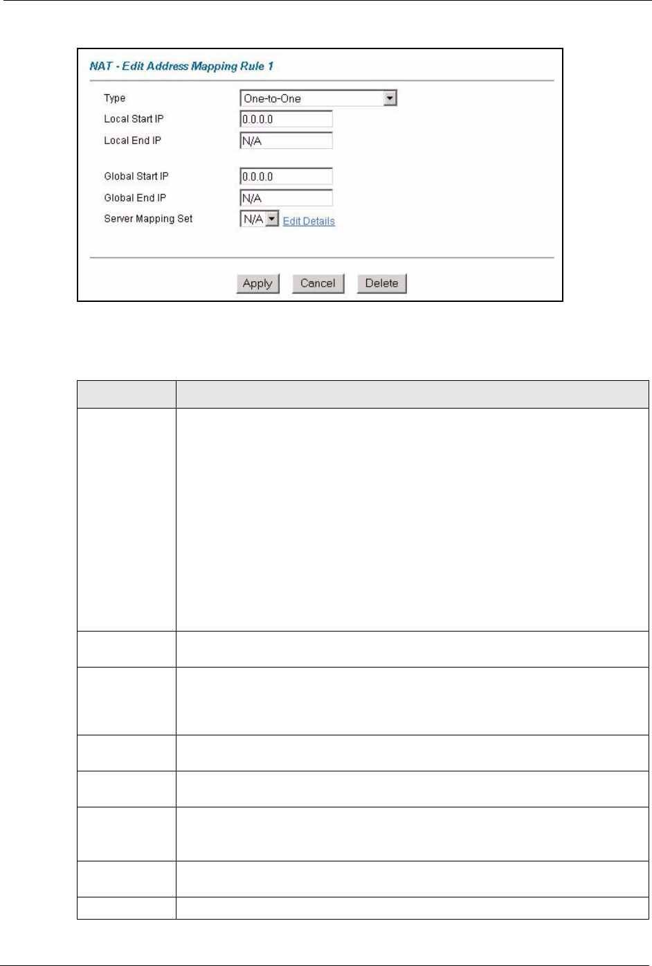
Figure 43 Edit Address Mapping Rule
The following table describes the fields in this screen.
Table 30 Edit Address Mapping Rule
LABEL DESCRIPTION
Type Choose the port mapping type from one of the following.
•One-to-One: One-to-One mode maps one local IP address to one global IP
address. Note that port numbers do not change for One-to-one NAT mapping
type.
•Many-to-One: Many-to-One mode maps multiple local IP addresses to one
global IP address. This is equivalent to SUA (i.e., PAT, port address translation),
ZyXEL's Single User Account feature that previous ZyXEL routers supported
only.
•Many-to-Many Overload: Many-to-Many Overload mode maps multiple local IP
addresses to shared global IP addresses.
•Many-to-Many No Overload: Many-to-Many No Overload mode maps each
local IP address to unique global IP addresses.
•Server: This type allows you to specify inside servers of different services behind
the NAT to be accessible to the outside world.
Local Start IP This is the starting local IP address (ILA). Local IP addresses are N/A for Server port
mapping.
Local End IP This is the end local IP address (ILA). If your rule is for all local IP addresses, then
enter 0.0.0.0 as the Local Start IP address and 255.255.255.255 as the Local End
IP address.
This field is N/A for One-to-One and Server mapping types.
Global Start IP This is the starting global IP address (IGA). Enter 0.0.0.0 here if you have a dynamic
IP address from your ISP.
Global End IP This is the ending global IP address (IGA). This field is N/A for One-to-One, Many-
to-One and Server mapping types.
Server Mapping
Set
Only available when Type is set to Server.
Select a number from the drop-down menu to choose a server set from the NAT -
Address Mapping Rules screen.
Edit Details Click this link to go to the NAT - Edit SUA/NAT Server Set screen to edit a server
set that you have selected in the Server Mapping Set field.
Apply Click Apply to save your changes back to the Prestige.
P-660H/HW/W-T Series User’ Guide
113 Chapter 7 Network Address Translation (NAT) Screens
Cancel Click Cancel to return to the previously saved settings.
Delete Click Delete to exit this screen without saving.
Table 30 Edit Address Mapping Rule (continued)
LABEL DESCRIPTION

P-660H/HW/W-T Series User’ Guide
Chapter 8 Dynamic DNS Setup 114
CHAPTER 8
Dynamic DNS Setup
This chapter discusses how to configure your Prestige to use Dynamic DNS.
8.1 Dynamic DNS Overview
Dynamic DNS allows you to update your current dynamic IP address with one or many
dynamic DNS services so that anyone can contact you (in NetMeeting, CU-SeeMe, etc.). You
can also access your FTP server or Web site on your own computer using a domain name (for
instance myhost.dhs.org, where myhost is a name of your choice) that will never change
instead of using an IP address that changes each time you reconnect. Your friends or relatives
will always be able to call you even if they don't know your IP address.
First of all, you need to have registered a dynamic DNS account with www.dyndns.org. This is
for people with a dynamic IP from their ISP or DHCP server that would still like to have a
domain name. The Dynamic DNS service provider will give you a password or key.
8.1.1 DYNDNS Wildcard
Enabling the wildcard feature for your host causes *.yourhost.dyndns.org to be aliased to the
same IP address as yourhost.dyndns.org. This feature is useful if you want to be able to use,
for example, www.yourhost.dyndns.org and still reach your hostname.
If you have a private WAN IP address, then you cannot use Dynamic DNS.
See Section 8.2 on page 114 for configuration instruction.
8.2 Configuring Dynamic DNS
To change your Prestige’s DDNS, click Dynamic DNS. The screen appears as shown.
See Section 8.1 on page 114 for more information.
P-660H/HW/W-T Series User’ Guide
115 Chapter 8 Dynamic DNS Setup
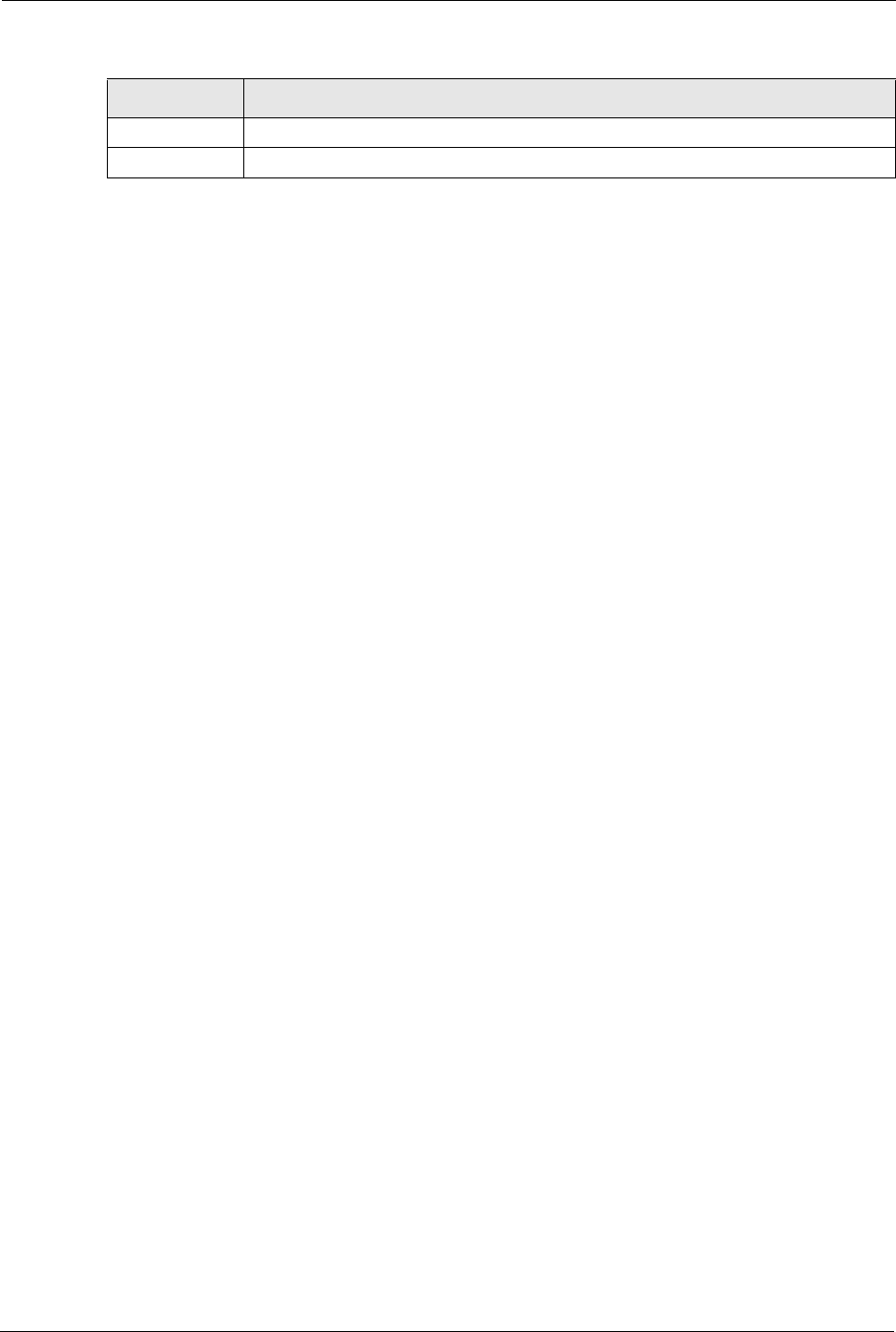
Figure 44 Dynamic DNS
The following table describes the fields in this screen.
Table 31 Dynamic DNS
LABEL DESCRIPTION
Active Select this check box to use dynamic DNS.
Service Provider This is the name of your Dynamic DNS service provider.
Host Names Type the domain name assigned to your Prestige by your Dynamic DNS provider.
E-mail Address Type your e-mail address.
User Type your user name.
Password Type the password assigned to you.
Enable Wildcard Select the check box to enable DYNDNS Wildcard.
Apply Click Apply to save your changes back to the Prestige.
Cancel Click Cancel to begin configuring this screen afresh.
P-660H/HW/W-T Series User’ Guide
Chapter 9 Time and Date 116
CHAPTER 9
Time and Date
This screen is not available on all models. Use this screen to configure the Prestige’s time and
date settings.
9.1 Configuring Time and Date
To change your Prestige’s time and date, click Time And Date. The screen appears as shown.
Use this screen to configure the Prestige’s time based on your local time zone.
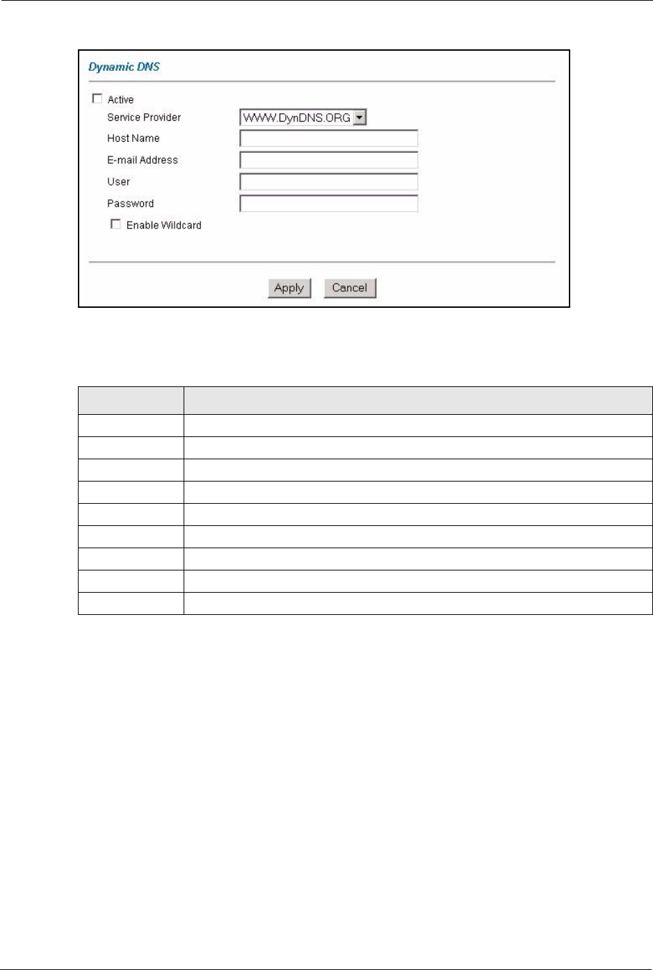
Figure 45 Time and Date
The following table describes the fields in this screen.

P-660H/HW/W-T Series User’ Guide
117 Chapter 9 Time and Date
Table 32 Time and Date
LABEL DESCRIPTION
Time Server
Use Protocol when
Bootup
Select the time service protocol that your time server sends when you turn on the
Prestige. Not all time servers support all protocols, so you may have to check with
your ISP/network administrator or use trial and error to find a protocol that works.
The main difference between them is the format.
Daytime (RFC 867) format is day/month/year/time zone of the server.
Time (RFC 868) format displays a 4-byte integer giving the total number of
seconds since 1970/1/1 at 0:0:0.
NTP (RFC 1305) is similar to Time (RFC 868).
Select None to enter the time and date manually.
IP Address or URL Enter the IP address or URL of your time server. Check with your ISP/network
administrator if you are unsure of this information.
Time and Date Choose the time zone of your location. This will set the time difference between
your time zone and Greenwich Mean Time (GMT).
Daylight Savings Select this option if you use daylight savings time. Daylight saving is a period from
late spring to early fall when many countries set their clocks ahead of normal local
time by one hour to give more daytime light in the evening.
Start Date Enter the month and day that your daylight-savings time starts on if you selected
Daylight Savings.
End Date Enter the month and day that your daylight-savings time ends on if you selected
Daylight Savings.
Synchronize
system clock with
Time Server now.
Select this option to have your Prestige use the time server (that you configured
above) to set its internal system clock.
Please wait for up to 60 seconds while the Prestige locates the time server. If the
Prestige cannot find the time server, please check the time server protocol and its
IP address. If the IP address was entered correctly, try pinging it for example to
test the connection.
Date
Current Date This field displays the date of your Prestige.
Each time you reload this page, the Prestige synchronizes the time with the time
server.
New Date (yyyy-
mm-dd)
This field displays the last updated date from the time server.
When you select None in the Use Protocol when Bootup field, enter the new
date in this field and then click Apply.
Time
Current Time This field displays the time of your Prestige.
Each time you reload this page, the Prestige synchronizes the time with the time
server.
New Time This field displays the last updated time from the time server.
When you select None in the Use Protocol when Bootup field, enter the new
time in this field and then click Apply.
Apply Click Apply to save your changes back to the Prestige.
Cancel Click Cancel to begin configuring this screen afresh.

P-660H/HW/W-T Series User’ Guide
Chapter 10 Firewalls 118
CHAPTER 10
Firewalls
This chapter gives some background information on firewalls and introduces the Prestige
firewall.
10.1 Firewall Overview
Originally, the term firewall referred to a construction technique designed to prevent the
spread of fire from one room to another. The networking term “firewall” is a system or group
of systems that enforces an access-control policy between two networks. It may also be
defined as a mechanism used to protect a trusted network from an untrusted network. Of
course, firewalls cannot solve every security problem. A firewall is one of the mechanisms
used to establish a network security perimeter in support of a network security policy. It
should never be the only mechanism or method employed. For a firewall to guard effectively,
you must design and deploy it appropriately. This requires integrating the firewall into a broad
information-security policy. In addition, specific policies must be implemented within the
firewall itself.
Refer to Section 11.5 on page 135 to configure default firewall settings.
Refer to Section 11.6 on page 136 to view firewall rules.
Refer to Section 11.6.1 on page 138 to configure firewall rules.
Refer to Section 11.7 on page 141 to configure a custom service.
Refer to Section 11.12.3 on page 151 to configure firewall thresholds.
10.2 Types of Firewalls
There are three main types of firewalls:
• Packet Filtering Firewalls
• Application-level Firewalls
• Stateful Inspection Firewalls
10.2.1 Packet Filtering Firewalls
Packet filtering firewalls restrict access based on the source/destination computer network
address of a packet and the type of application.

P-660H/HW/W-T Series User’ Guide
119 Chapter 10 Firewalls
10.2.2 Application-level Firewalls
Application-level firewalls restrict access by serving as proxies for external servers. Since they
use programs written for specific Internet services, such as HTTP, FTP and telnet, they can
evaluate network packets for valid application-specific data. Application-level gateways have
a number of general advantages over the default mode of permitting application traffic directly
to internal hosts:
Information hiding prevents the names of internal systems from being made known via DNS
to outside systems, since the application gateway is the only host whose name must be made
known to outside systems.
Robust authentication and logging pre-authenticates application traffic before it reaches
internal hosts and causes it to be logged more effectively than if it were logged with standard
host logging. Filtering rules at the packet filtering router can be less complex than they would
be if the router needed to filter application traffic and direct it to a number of specific systems.
The router need only allow application traffic destined for the application gateway and reject
the rest.
10.2.3 Stateful Inspection Firewalls
Stateful inspection firewalls restrict access by screening data packets against defined access
rules. They make access control decisions based on IP address and protocol. They also
"inspect" the session data to assure the integrity of the connection and to adapt to dynamic
protocols. These firewalls generally provide the best speed and transparency, however, they
may lack the granular application level access control or caching that some proxies support.
See Section 10.5 on page 124 for more information on stateful inspection.
Firewalls, of one type or another, have become an integral part of standard security solutions
for enterprises.
10.3 Introduction to ZyXEL’s Firewall
The Prestige firewall is a stateful inspection firewall and is designed to protect against Denial
of Service attacks when activated (in SMT menu 21.2 or in the web configurator). The
Prestige’s purpose is to allow a private Local Area Network (LAN) to be securely connected
to the Internet. The Prestige can be used to prevent theft, destruction and modification of data,
as well as log events, which may be important to the security of your network. The Prestige
also has packet filtering capabilities.
The Prestige is installed between the LAN and the Internet. This allows it to act as a secure
gateway for all data passing between the Internet and the LAN.
The Prestige has one DSL/ISDN port and one Ethernet LAN port, which physically separate
the network into two areas.
• The DSL/ISDN port connects to the Internet.
P-660H/HW/W-T Series User’ Guide
Chapter 10 Firewalls 120
• The LAN (Local Area Network) port attaches to a network of computers, which needs
security from the outside world. These computers will have access to Internet services
such as e-mail, FTP, and the World Wide Web. However, “inbound access” will not be
allowed unless you configure remote management or create a firewall rule to allow a
remote host to use a specific service.
10.3.1 Denial of Service Attacks
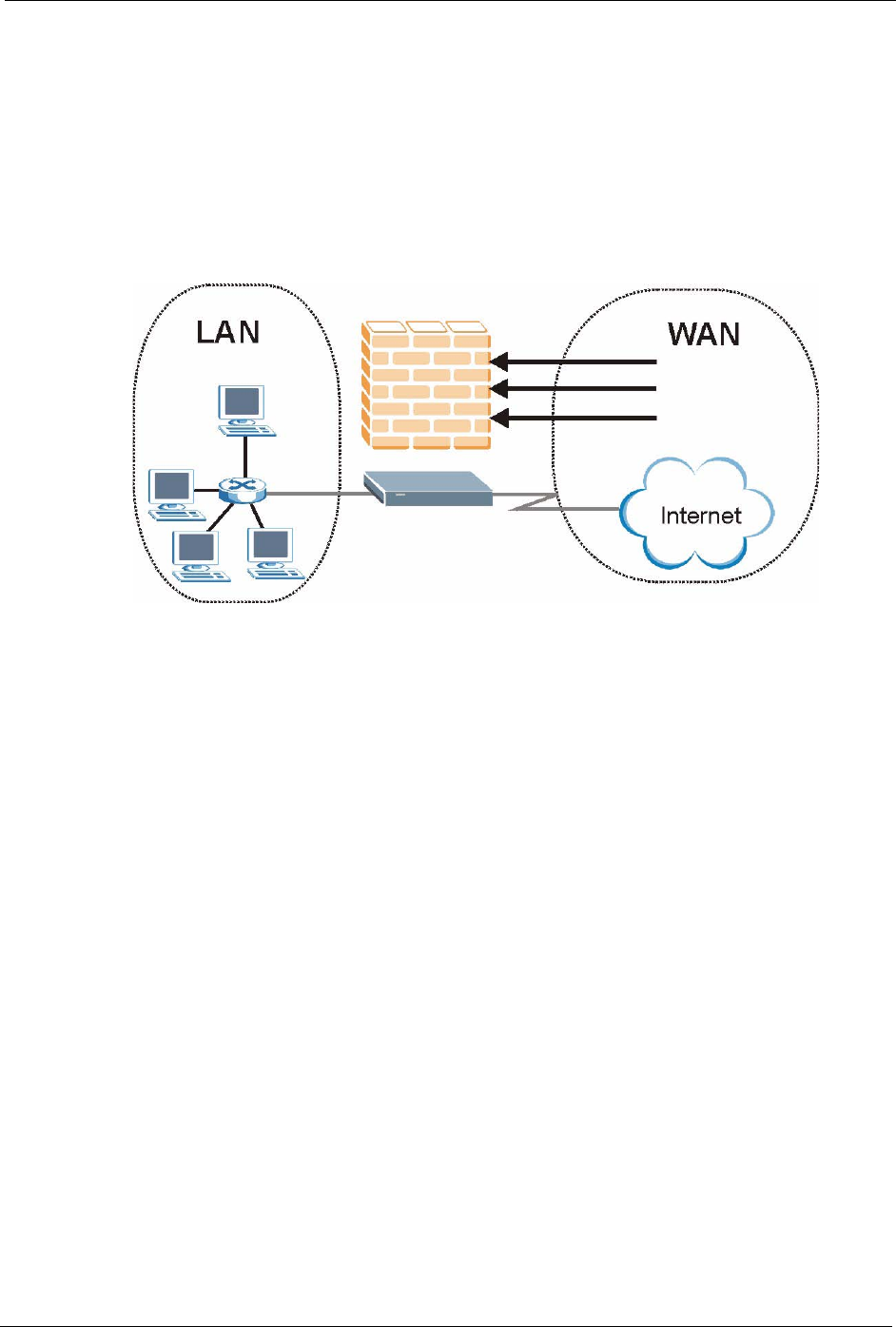
Figure 46 Prestige Firewall Application
10.4 Denial of Service
Denials of Service (DoS) attacks are aimed at devices and networks with a connection to the
Internet. Their goal is not to steal information, but to disable a device or network so users no
longer have access to network resources. The Prestige is pre-configured to automatically
detect and thwart all known DoS attacks.
10.4.1 Basics
Computers share information over the Internet using a common language called TCP/IP. TCP/
IP, in turn, is a set of application protocols that perform specific functions. An “extension
number”, called the "TCP port" or "UDP port" identifies these protocols, such as HTTP
(Web), FTP (File Transfer Protocol), POP3 (E-mail), etc. For example, Web traffic by default
uses TCP port 80.
When computers communicate on the Internet, they are using the client/server model, where
the server "listens" on a specific TCP/UDP port for information requests from remote client
computers on the network. For example, a Web server typically listens on port 80. Please note
that while a computer may be intended for use over a single port, such as Web on port 80,
other ports are also active. If the person configuring or managing the computer is not careful, a
hacker could attack it over an unprotected port.
Some of the most common IP ports are:

P-660H/HW/W-T Series User’ Guide
121 Chapter 10 Firewalls
10.4.2 Types of DoS Attacks
There are four types of DoS attacks:
1Those that exploit bugs in a TCP/IP implementation.
2Those that exploit weaknesses in the TCP/IP specification.
3Brute-force attacks that flood a network with useless data.
4IP Spoofing.
5"Ping of Death" and "Teardrop" attacks exploit bugs in the TCP/IP implementations of
various computer and host systems.
• Ping of Death uses a "ping" utility to create an IP packet that exceeds the maximum
65,536 bytes of data allowed by the IP specification. The oversize packet is then sent to
an unsuspecting system. Systems may crash, hang or reboot.
• Teardrop attack exploits weaknesses in the re-assembly of IP packet fragments. As data is
transmitted through a network, IP packets are often broken up into smaller chunks. Each
fragment looks like the original IP packet except that it contains an offset field that says,
for instance, "This fragment is carrying bytes 200 through 400 of the original (non
fragmented) IP packet." The Teardrop program creates a series of IP fragments with
overlapping offset fields. When these fragments are reassembled at the destination, some
systems will crash, hang, or reboot.
6Weaknesses in the TCP/IP specification leave it open to "SYN Flood" and "LAND"
attacks. These attacks are executed during the handshake that initiates a communication
session between two applications.
Table 33 Common IP Ports
21 FTP 53 DNS
23 Telnet 80 HTTP
25 SMTP 110 POP3
P-660H/HW/W-T Series User’ Guide
Chapter 10 Firewalls 122
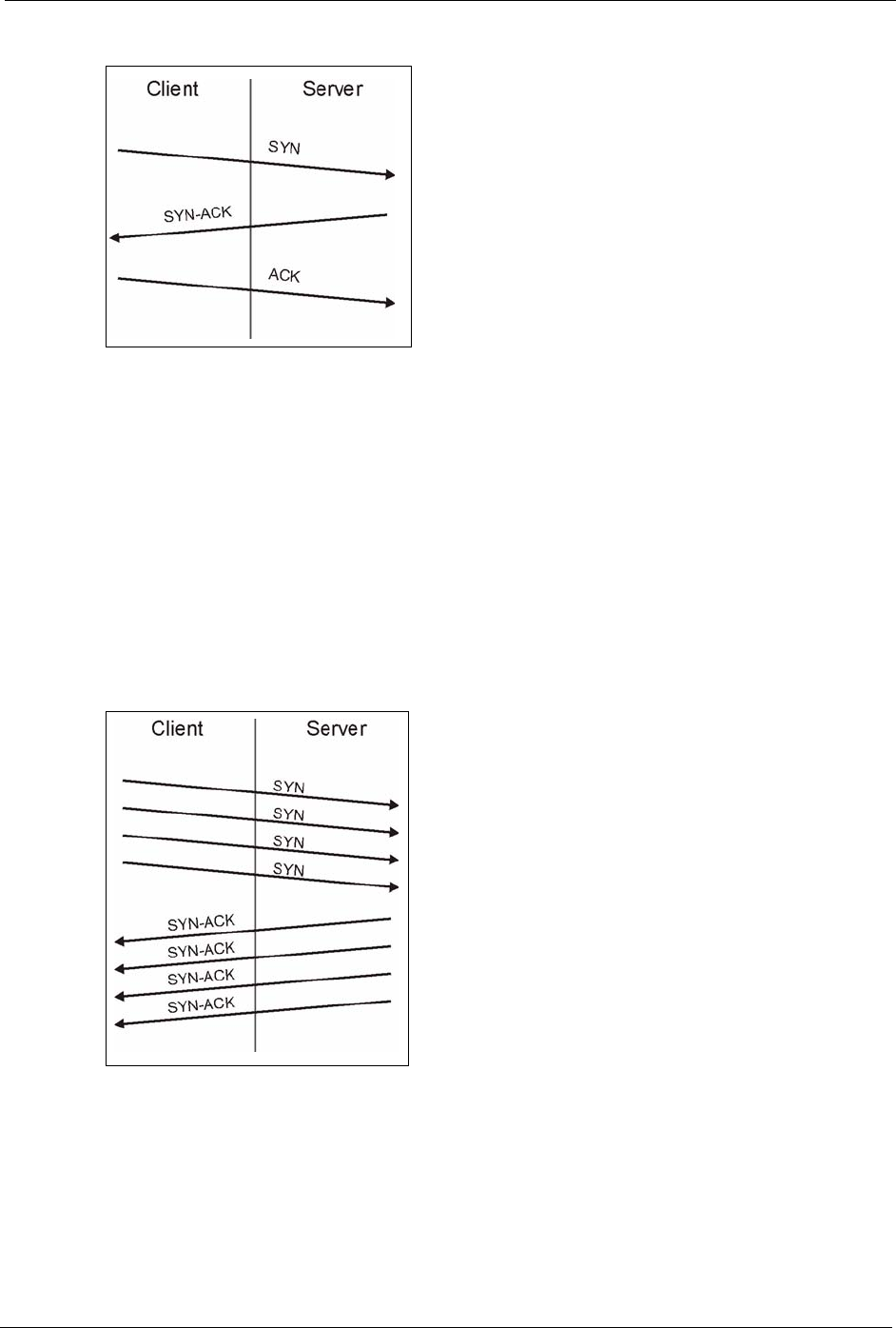
Figure 47 Three-Way Handshake
Under normal circumstances, the application that initiates a session sends a SYN
(synchronize) packet to the receiving server. The receiver sends back an ACK
(acknowledgment) packet and its own SYN, and then the initiator responds with an ACK
(acknowledgment). After this handshake, a connection is established.
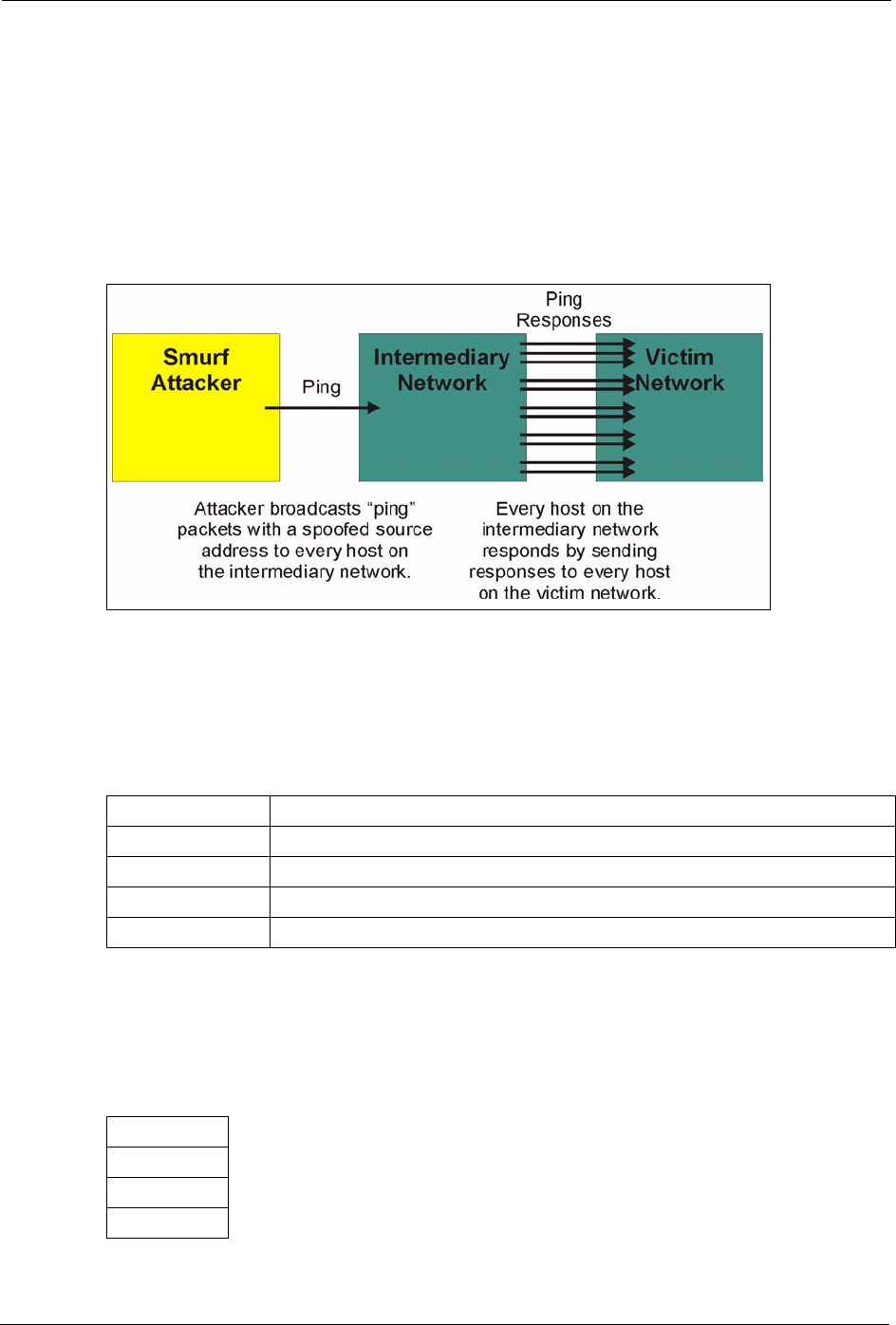
•SYN Attack floods a targeted system with a series of SYN packets. Each packet causes
the targeted system to issue a SYN-ACK response. While the targeted system waits for
the ACK that follows the SYN-ACK, it queues up all outstanding SYN-ACK responses
on what is known as a backlog queue. SYN-ACKs are moved off the queue only when an
ACK comes back or when an internal timer (which is set at relatively long intervals)
terminates the three-way handshake. Once the queue is full, the system will ignore all
incoming SYN requests, making the system unavailable for legitimate users.
Figure 48 SYN Flood
•In a LAND Attack, hackers flood SYN packets into the network with a spoofed source
IP address of the targeted system. This makes it appear as if the host computer sent the
packets to itself, making the system unavailable while the target system tries to respond
to itself.
7A brute-force attack, such as a "Smurf" attack, targets a feature in the IP specification
known as directed or subnet broadcasting, to quickly flood the target network with
useless data. A Smurf hacker floods a router with Internet Control Message Protocol
P-660H/HW/W-T Series User’ Guide
123 Chapter 10 Firewalls
(ICMP) echo request packets (pings). Since the destination IP address of each packet is
the broadcast address of the network, the router will broadcast the ICMP echo request
packet to all hosts on the network. If there are numerous hosts, this will create a large
amount of ICMP echo request and response traffic. If a hacker chooses to spoof the
source IP address of the ICMP echo request packet, the resulting ICMP traffic will not
only clog up the "intermediary" network, but will also congest the network of the spoofed
source IP address, known as the "victim" network. This flood of broadcast traffic
consumes all available bandwidth, making communications impossible.
Figure 49 Smurf Attack
10.4.2.1 ICMP Vulnerability
ICMP is an error-reporting protocol that works in concert with IP. The following ICMP types
trigger an alert:
10.4.2.2 Illegal Commands (NetBIOS and SMTP)
The only legal NetBIOS commands are the following - all others are illegal.
Table 34 ICMP Commands That Trigger Alerts
5REDIRECT
13 TIMESTAMP_REQUEST
14 TIMESTAMP_REPLY
17 ADDRESS_MASK_REQUEST
18 ADDRESS_MASK_REPLY
Table 35 Legal NetBIOS Commands
MESSAGE:
REQUEST:
POSITIVE:
VE:

P-660H/HW/W-T Series User’ Guide
Chapter 10 Firewalls 124
All SMTP commands are illegal except for those displayed in the following tables.
10.4.2.3 Traceroute
Traceroute is a utility used to determine the path a packet takes between two endpoints.
Sometimes when a packet filter firewall is configured incorrectly an attacker can traceroute
the firewall gaining knowledge of the network topology inside the firewall.
Often, many DoS attacks also employ a technique known as "IP Spoofing" as part of their
attack. IP Spoofing may be used to break into systems, to hide the hacker's identity, or to
magnify the effect of the DoS attack. IP Spoofing is a technique used to gain unauthorized
access to computers by tricking a router or firewall into thinking that the communications are
coming from within the trusted network. To engage in IP spoofing, a hacker must modify the
packet headers so that it appears that the packets originate from a trusted host and should be
allowed through the router or firewall. The Prestige blocks all IP Spoofing attempts.
10.5 Stateful Inspection
With stateful inspection, fields of the packets are compared to packets that are already known
to be trusted. For example, if you access some outside service, the proxy server remembers
things about your original request, like the port number and source and destination addresses.
This “remembering” is called saving the state. When the outside system responds to your
request, the firewall compares the received packets with the saved state to determine if they
are allowed in. The Prestige uses stateful packet inspection to protect the private LAN from
hackers and vandals on the Internet. By default, the Prestige’s stateful inspection allows all
communications to the Internet that originate from the LAN, and blocks all traffic to the LAN
that originates from the Internet. In summary, stateful inspection:
• Allows all sessions originating from the LAN (local network) to the WAN (Internet).
• Denies all sessions originating from the WAN to the LAN.
RETARGET:
KEEPALIVE:
Table 36 Legal SMTP Commands
AUTH DATA EHLO ETRN EXPN HELO HELP MAIL NOOP
QUIT RCPT RSET SAML SEND SOML TURN VRFY
Table 35 Legal NetBIOS Commands
P-660H/HW/W-T Series User’ Guide
125 Chapter 10 Firewalls
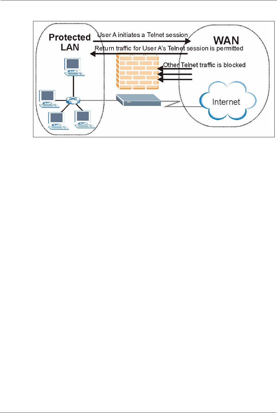
Figure 50 Stateful Inspection
The previous figure shows the Prestige’s default firewall rules in action as well as
demonstrates how stateful inspection works. User A can initiate a Telnet session from within
the LAN and responses to this request are allowed. However other Telnet traffic initiated from
the WAN is blocked.
10.5.1 Stateful Inspection Process
In this example, the following sequence of events occurs when a TCP packet leaves the LAN
network through the firewall's WAN interface. The TCP packet is the first in a session, and the
packet's application layer protocol is configured for a firewall rule inspection:
1The packet travels from the firewall's LAN to the WAN.
2The packet is evaluated against the interface's existing outbound access list, and the
packet is permitted (a denied packet would simply be dropped at this point).
3The packet is inspected by a firewall rule to determine and record information about the
state of the packet's connection. This information is recorded in a new state table entry
created for the new connection. If there is not a firewall rule for this packet and it is not an
attack, then the settings in the Default Policy screen determine the action for this packet.
4Based on the obtained state information, a firewall rule creates a temporary access list
entry that is inserted at the beginning of the WAN interface's inbound extended access
list. This temporary access list entry is designed to permit inbound packets of the same
connection as the outbound packet just inspected.
5The outbound packet is forwarded out through the interface.
6Later, an inbound packet reaches the interface. This packet is part of the connection
previously established with the outbound packet. The inbound packet is evaluated against
the inbound access list, and is permitted because of the temporary access list entry
previously created.
7The packet is inspected by a firewall rule, and the connection's state table entry is updated
as necessary. Based on the updated state information, the inbound extended access list

P-660H/HW/W-T Series User’ Guide
Chapter 10 Firewalls 126
temporary entries might be modified, in order to permit only packets that are valid for the
current state of the connection.
8Any additional inbound or outbound packets that belong to the connection are inspected
to update the state table entry and to modify the temporary inbound access list entries as
required, and are forwarded through the interface.
9When the connection terminates or times out, the connection's state table entry is deleted
and the connection's temporary inbound access list entries are deleted.
10.5.2 Stateful Inspection and the Prestige
Additional rules may be defined to extend or override the default rules. For example, a rule
may be created which will:
• Block all traffic of a certain type, such as IRC (Internet Relay Chat), from the LAN to the
Internet.
• Allow certain types of traffic from the Internet to specific hosts on the LAN.
• Allow access to a Web server to everyone but competitors.
• Restrict use of certain protocols, such as Telnet, to authorized users on the LAN.
These custom rules work by evaluating the network traffic’s Source IP address, Destination IP
address, IP protocol type, and comparing these to rules set by the administrator.
Note: The ability to define firewall rules is a very powerful tool. Using custom rules, it
is possible to disable all firewall protection or block all access to the Internet.
Use extreme caution when creating or deleting firewall rules. Test changes
after creating them to make sure they work correctly.
Below is a brief technical description of how these connections are tracked. Connections may
either be defined by the upper protocols (for instance, TCP), or by the Prestige itself (as with
the "virtual connections" created for UDP and ICMP).
10.5.3 TCP Security
The Prestige uses state information embedded in TCP packets. The first packet of any new
connection has its SYN flag set and its ACK flag cleared; these are "initiation" packets. All
packets that do not have this flag structure are called "subsequent" packets, since they
represent data that occurs later in the TCP stream.
If an initiation packet originates on the WAN, this means that someone is trying to make a
connection from the Internet into the LAN. Except in a few special cases (see "Upper Layer
Protocols" shown next), these packets are dropped and logged.
If an initiation packet originates on the LAN, this means that someone is trying to make a
connection from the LAN to the Internet. Assuming that this is an acceptable part of the
security policy (as is the case with the default policy), the connection will be allowed. A cache
entry is added which includes connection information such as IP addresses, TCP ports,
sequence numbers, etc.

P-660H/HW/W-T Series User’ Guide
127 Chapter 10 Firewalls
When the Prestige receives any subsequent packet (from the Internet or from the LAN), its
connection information is extracted and checked against the cache. A packet is only allowed to
pass through if it corresponds to a valid connection (that is, if it is a response to a connection
which originated on the LAN).
10.5.4 UDP/ICMP Security
UDP and ICMP do not themselves contain any connection information (such as sequence
numbers). However, at the very minimum, they contain an IP address pair (source and
destination). UDP also contains port pairs, and ICMP has type and code information. All of
this data can be analyzed in order to build "virtual connections" in the cache.
For instance, any UDP packet that originates on the LAN will create a cache entry. Its IP
address and port pairs will be stored. For a short period of time, UDP packets from the WAN
that have matching IP and UDP information will be allowed back in through the firewall.
A similar situation exists for ICMP, except that the Prestige is even more restrictive.
Specifically, only outgoing echoes will allow incoming echo replies, outgoing address mask
requests will allow incoming address mask replies, and outgoing timestamp requests will
allow incoming timestamp replies. No other ICMP packets are allowed in through the firewall,
simply because they are too dangerous and contain too little tracking information. For
instance, ICMP redirect packets are never allowed in, since they could be used to reroute
traffic through attacking machines.
10.5.5 Upper Layer Protocols
Some higher layer protocols (such as FTP and RealAudio) utilize multiple network
connections simultaneously. In general terms, they usually have a "control connection" which
is used for sending commands between endpoints, and then "data connections" which are used
for transmitting bulk information.
Consider the FTP protocol. A user on the LAN opens a control connection to a server on the
Internet and requests a file. At this point, the remote server will open a data connection from
the Internet. For FTP to work properly, this connection must be allowed to pass through even
though a connection from the Internet would normally be rejected.
In order to achieve this, the Prestige inspects the application-level FTP data. Specifically, it
searches for outgoing "PORT" commands, and when it sees these, it adds a cache entry for the
anticipated data connection. This can be done safely, since the PORT command contains
address and port information, which can be used to uniquely identify the connection.
Any protocol that operates in this way must be supported on a case-by-case basis. You can use
the web configurator’s Custom Ports feature to do this.
10.6 Guidelines for Enhancing Security with Your Firewall
• Change the default password via SMT or web configurator.

P-660H/HW/W-T Series User’ Guide
Chapter 10 Firewalls 128
• Limit who can telnet into your router.
• Don't enable any local service (such as SNMP or NTP) that you don't use. Any enabled
service could present a potential security risk. A determined hacker might be able to find
creative ways to misuse the enabled services to access the firewall or the network.
• For local services that are enabled, protect against misuse. Protect by configuring the
services to communicate only with specific peers, and protect by configuring rules to
block packets for the services at specific interfaces.
• Protect against IP spoofing by making sure the firewall is active.
• Keep the firewall in a secured (locked) room.
10.6.1 Security In General
You can never be too careful! Factors outside your firewall, filtering or NAT can cause
security breaches. Below are some generalizations about what you can do to minimize them.
• Encourage your company or organization to develop a comprehensive security plan.
Good network administration takes into account what hackers can do and prepares
against attacks. The best defense against hackers and crackers is information. Educate all
employees about the importance of security and how to minimize risk. Produce lists like
this one!
• DSL or cable modem connections are “always-on” connections and are particularly
vulnerable because they provide more opportunities for hackers to crack your system.
Turn your computer off when not in use.
• Never give out a password or any sensitive information to an unsolicited telephone call or
e-mail.
• Never e-mail sensitive information such as passwords, credit card information, etc.,
without encrypting the information first.
• Never submit sensitive information via a web page unless the web site uses secure
connections. You can identify a secure connection by looking for a small “key” icon on
the bottom of your browser (Internet Explorer 3.02 or better or Netscape 3.0 or better). If
a web site uses a secure connection, it is safe to submit information. Secure web
transactions are quite difficult to crack.
• Never reveal your IP address or other system networking information to people outside
your company. Be careful of files e-mailed to you from strangers. One common way of
getting BackOrifice on a system is to include it as a Trojan horse with other files.
• Change your passwords regularly. Also, use passwords that are not easy to figure out.
The most difficult passwords to crack are those with upper and lower case letters,
numbers and a symbol such as % or #.
• Upgrade your software regularly. Many older versions of software, especially web
browsers, have well known security deficiencies. When you upgrade to the latest
versions, you get the latest patches and fixes.
• If you use “chat rooms” or IRC sessions, be careful with any information you reveal to
strangers.
• If your system starts exhibiting odd behavior, contact your ISP. Some hackers will set off
hacks that cause your system to slowly become unstable or unusable.

P-660H/HW/W-T Series User’ Guide
129 Chapter 10 Firewalls
• Always shred confidential information, particularly about your computer, before
throwing it away. Some hackers dig through the trash of companies or individuals for
information that might help them in an attack.
10.7 Packet Filtering Vs Firewall
Below are some comparisons between the Prestige’s filtering and firewall functions.
10.7.1 Packet Filtering:
• The router filters packets as they pass through the router’s interface according to the filter
rules you designed.
• Packet filtering is a powerful tool, yet can be complex to configure and maintain,
especially if you need a chain of rules to filter a service.
• Packet filtering only checks the header portion of an IP packet.
10.7.1.1 When To Use Filtering
• To block/allow LAN packets by their MAC addresses.
• To block/allow special IP packets which are neither TCP nor UDP, nor ICMP packets.
• To block/allow both inbound (WAN to LAN) and outbound (LAN to WAN) traffic
between the specific inside host/network "A" and outside host/network "B". If the filter
blocks the traffic from A to B, it also blocks the traffic from B to A. Filters can not
distinguish traffic originating from an inside host or an outside host by IP address.
• To block/allow IP trace route.
10.7.2 Firewall
• The firewall inspects packet contents as well as their source and destination addresses.
Firewalls of this type employ an inspection module, applicable to all protocols, that
understands data in the packet is intended for other layers, from the network layer (IP
headers) up to the application layer.
• The firewall performs stateful inspection. It takes into account the state of connections it
handles so that, for example, a legitimate incoming packet can be matched with the
outbound request for that packet and allowed in. Conversely, an incoming packet
masquerading as a response to a nonexistent outbound request can be blocked.
• The firewall uses session filtering, i.e., smart rules, that enhance the filtering process and
control the network session rather than control individual packets in a session.
• The firewall provides e-mail service to notify you of routine reports and when alerts
occur.
10.7.2.1 When To Use The Firewall
• To prevent DoS attacks and prevent hackers cracking your network.

P-660H/HW/W-T Series User’ Guide
Chapter 10 Firewalls 130
• A range of source and destination IP addresses as well as port numbers can be specified
within one firewall rule making the firewall a better choice when complex rules are
required.
• To selectively block/allow inbound or outbound traffic between inside host/networks and
outside host/networks. Remember that filters can not distinguish traffic originating from
an inside host or an outside host by IP address.
• The firewall performs better than filtering if you need to check many rules.
• Use the firewall if you need routine e-mail reports about your system or need to be alerted
when attacks occur.
• The firewall can block specific URL traffic that might occur in the future. The URL can
be saved in an Access Control List (ACL) database.

P-660H/HW/W-T Series User’ Guide
131 Chapter 10 Firewalls

P-660H/HW/W-T Series User’ Guide
Chapter 11 Firewall Configuration 132
CHAPTER 11
Firewall Configuration
This chapter shows you how to enable and configure the Prestige firewall.
11.1 Access Methods
The web configurator is, by far, the most comprehensive firewall configuration tool your
Prestige has to offer. For this reason, it is recommended that you configure your firewall using
the web configurator. SMT screens allow you to activate the firewall. CLI commands provide
limited configuration options and are only recommended for advanced users.
11.2 Firewall Policies Overview
Firewall rules are grouped based on the direction of travel of packets to which they apply:
Note: The LAN includes both the LAN port and the WLAN.
By default, the Prestige’s stateful packet inspection allows packets traveling in the following
directions:
• LAN to LAN/ Router
This allows computers on the LAN to manage the Prestige and communicate between
networks or subnets connected to the LAN interface.
• LAN to WAN
By default, the Prestige’s stateful packet inspection blocks packets traveling in the following
directions:
•WAN to LAN
•WAN to WAN/ Router
This prevents computers on the WAN from using the Prestige as a gateway to
communicate with other computers on the WAN and/or managing the Prestige.
You may define additional rules and sets or modify existing ones but please exercise
extreme caution in doing so.
• LAN to LAN/ Router • WAN to LAN
• LAN to WAN • WAN to WAN/ Router

P-660H/HW/W-T Series User’ Guide
133 Chapter 11 Firewall Configuration
Note: If you configure firewall rules without a good understanding of how they work,
you might inadvertently introduce security risks to the firewall and to the
protected network. Make sure you test your rules after you configure them.
For example, you may create rules to:
• Block certain types of traffic, such as IRC (Internet Relay Chat), from the LAN to the
Internet.
• Allow certain types of traffic, such as Lotus Notes database synchronization, from
specific hosts on the Internet to specific hosts on the LAN.
• Allow everyone except your competitors to access a Web server.
• Restrict use of certain protocols, such as Telnet, to authorized users on the LAN.
These custom rules work by comparing the Source IP address, Destination IP address and IP
protocol type of network traffic to rules set by the administrator. Your customized rules take
precedence and override the Prestige’s default rules.
11.3 Rule Logic Overview
Note: Study these points carefully before configuring rules.
11.3.1 Rule Checklist
State the intent of the rule. For example, “This restricts all IRC access from the LAN to the
Internet.” Or, “This allows a remote Lotus Notes server to synchronize over the Internet to an
inside Notes server.”
1Is the intent of the rule to forward or block traffic?
2What direction of traffic does the rule apply to?
3What IP services will be affected?
4What computers on the LAN are to be affected (if any)?
5What computers on the Internet will be affected? The more specific, the better. For
example, if traffic is being allowed from the Internet to the LAN, it is better to allow only
certain machines on the Internet to access the LAN.
11.3.2 Security Ramifications
1Once the logic of the rule has been defined, it is critical to consider the security
ramifications created by the rule:
2Does this rule stop LAN users from accessing critical resources on the Internet? For
example, if IRC is blocked, are there users that require this service?
3Is it possible to modify the rule to be more specific? For example, if IRC is blocked for all
users, will a rule that blocks just certain users be more effective?

P-660H/HW/W-T Series User’ Guide
Chapter 11 Firewall Configuration 134
4Does a rule that allows Internet users access to resources on the LAN create a security
vulnerability? For example, if FTP ports (TCP 20, 21) are allowed from the Internet to the
LAN, Internet users may be able to connect to computers with running FTP servers.
5Does this rule conflict with any existing rules?
6Once these questions have been answered, adding rules is simply a matter of plugging the
information into the correct fields in the web configurator screens.
11.3.3 Key Fields For Configuring Rules
11.3.3.1 Action
Should the action be to Block or Forward? “Block” means the firewall silently discards the
packet.
11.3.3.2 Service
Select the service from the Service scrolling list box. If the service is not listed, it is necessary
to first define it. See Section 11.10 on page 146 for more information on predefined services.
11.3.3.3 Source Address
What is the connection’s source address; is it on the LAN, WAN? Is it a single IP, a range of
IPs or a subnet?
11.3.3.4 Destination Address
What is the connection’s destination address; is it on the LAN, WAN? Is it a single IP, a range
of IPs or a subnet?
11.4 Connection Direction
This section describes examples for firewall rules for connections going from LAN to WAN
and from WAN to LAN.
LAN to LAN/ Router, WAN to WAN/ Router rules apply to packets coming in on the
associated interface (LAN, WAN respectively). LAN to LAN/ Router means policies for
LAN-to-Prestige (the policies for managing the Prestige through the LAN interface) and
policies for LAN-to-LAN (the policies that control routing between two subnets on the LAN).
Similarly, WAN to WAN/ Router polices apply in the same way to the WAN ports.
11.4.1 LAN to WAN Rules
The default rule for LAN to WAN traffic is that all users on the LAN are allowed non-
restricted access to the WAN. When you configure a LAN to WAN rule, you in essence want
to limit some or all users from accessing certain services on the WAN. WAN to LAN Rules
P-660H/HW/W-T Series User’ Guide
135 Chapter 11 Firewall Configuration
The default rule for WAN to LAN traffic blocks all incoming connections (WAN to LAN). If
you wish to allow certain WAN users to have access to your LAN, you will need to create
custom rules to allow it.
11.4.2 Alerts
Alerts are reports on events, such as attacks, that you may want to know about right away. You
can choose to generate an alert when an attack is detected in the Edit Rule screen (select the
Send Alert Message to Administrator When Matched check box) or when a rule is matched
in the Edit Rule screen. When an event generates an alert, a message can be immediately sent
to an e-mail account that you specify in the Log Settings screen (see the chapter on logs).
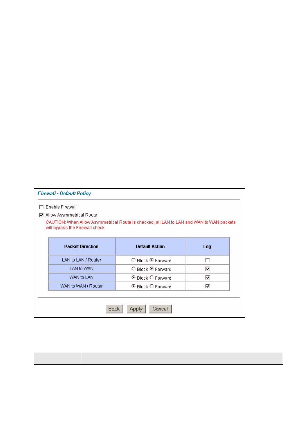
11.5 Configuring Default Firewall Policy
Click Firewall and then Default Policy to display the following screen. Activate the firewall
by selecting the Firewall Enabled check box as seen in the following screen.
Refer to Section 10.1 on page 118 for more information.
Figure 51 Firewall: Default Policy
The following table describes the labels in this screen.
Table 37 Firewall: Default Policy
LABEL DESCRIPTION
Firewall Enabled Select this check box to activate the firewall. The Prestige performs access control
and protects against Denial of Service (DoS) attacks when the firewall is activated.
Allow
Asymmetrical
Route
Select this check box to have the Prestige firewall permit the use of triangle route
topology on the network. See the appendix for more on triangle route topology.

P-660H/HW/W-T Series User’ Guide
Chapter 11 Firewall Configuration 136
11.6 Rule Summary
Note: The ordering of your rules is very important as rules are applied in turn.
Refer to Section 10.1 on page 118 for more information.
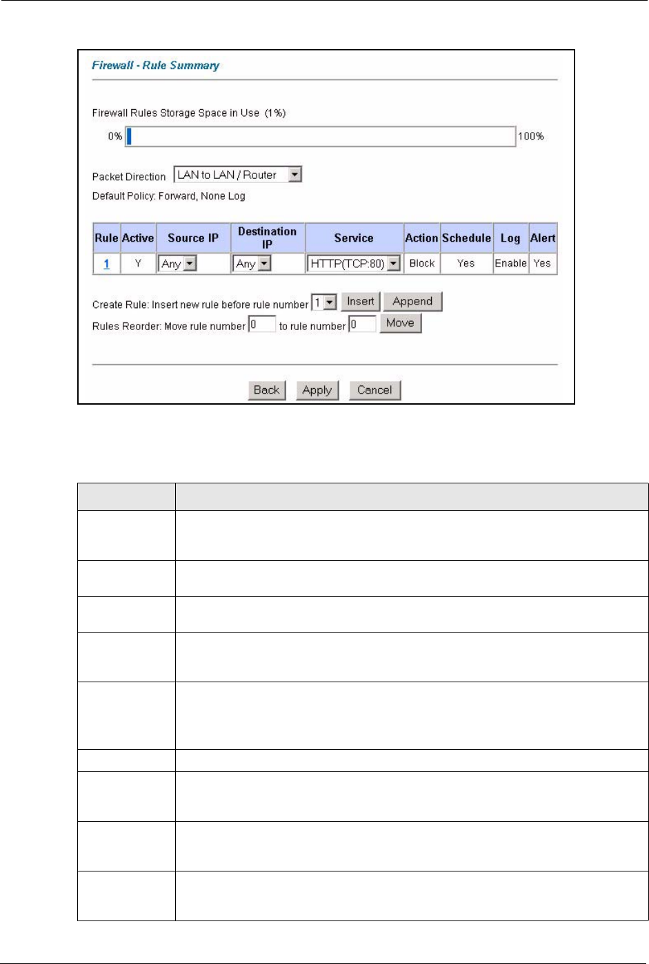
Click on Firewall, then Rule Summary to bring up the following screen. This screen is a
summary of the existing rules. Note the order in which the rules are listed.
Packet Direction This is the direction of travel of packets (LAN to LAN/Router, LAN to WAN, WAN
to WAN/Router, WAN to LAN).
Firewall rules are grouped based on the direction of travel of packets to which they
apply. For example, LAN to LAN/Router means packets traveling from a
computer/subnet on the LAN to either another computer/subnet on the LAN
interface of the Prestige or the Prestige itself.
Default Action Use the radio buttons to select whether to Block (silently discard) or Forward
(allow the passage of) packets that are traveling in the selected direction.
Log Select the check box to create a log (when the above action is taken) for packets
that are traveling in the selected direction and do not match any of the rules below.
Back Click Back to return to the previous screen.
Apply Click Apply to save your changes back to the Prestige.
Cancel Click Cancel to begin configuring this screen afresh.
Table 37 Firewall: Default Policy (continued)
LABEL DESCRIPTION
P-660H/HW/W-T Series User’ Guide
137 Chapter 11 Firewall Configuration
Figure 52 Firewall: Rule Summary
The following table describes the labels in this screen.
Table 38 Rule Summary
LABEL DESCRIPTION
Firewall Rules
Storage Space
in Use
This read-only bar shows how much of the Prestige's memory for recording firewall
rules it is currently using. When you are using 80% or less of the storage space, the
bar is green. When the amount of space used is over 80%, the bar is red.
Packet Direction Use the drop-down list box to select a direction of travel of packets for which you
want to configure firewall rules.
Default Policy This field displays the default action and log policy you selected in the Default Rule
screen for the packet direction shown in the field above.
The following read-only fields summarize the rules you have created that apply to
traffic traveling in the selected packet direction. The firewall rules that you configure
(summarized below) take priority over the general firewall action settings above.
Rule This is your firewall rule number. The ordering of your rules is important as rules are
applied in turn.
Click a rule’s number to go to the Firewall Edit Rule screen to configure or edit a
firewall rule.
Active This field displays whether a firewall is turned on (Y) or not (N).
Source IP This drop-down list box displays the source addresses or ranges of addresses to
which this firewall rule applies. Please note that a blank source or destination
address is equivalent to Any.
Destination IP This drop-down list box displays the destination addresses or ranges of addresses to
which this firewall rule applies. Please note that a blank source or destination
address is equivalent to Any.
Service This drop-down list box displays the services to which this firewall rule applies.
Please note that a blank service type is equivalent to Any. See Section 11.10 on
page 146 for more information.
P-660H/HW/W-T Series User’ Guide
Chapter 11 Firewall Configuration 138
11.6.1 Configuring Firewall Rules
Refer to Section 10.1 on page 118 for more information.
Follow these directions to create a new rule.
1In the Rule Summary screen, type the index number for where you want to put the rule.
For example, if you type “6”, your new rule becomes number 6 and the previous rule 6 (if
there is one) becomes rule 7.
2Click Insert to display this screen and refer to the following table for information on the
labels.
Action This is the specified action for that rule, either Block or Forward. Note that Block
means the firewall silently discards the packet.
Schedule This field tells you whether a schedule is specified (Yes) or not (No).
Log This field shows you whether a log is created when packets match this rule
(Enabled) or not (Disable).
Alert This field tells you whether this rule generates an alert (Yes) or not (No) when the
rule is matched.
Insert/Append Type the index number for where you want to put a rule. For example, if you type “6”,
your new rule becomes number 6 and the previous rule 6 (if there is one) becomes
rule 7.
Click Insert to add a new firewall rule before the specified index number.
Click Append to add a new firewall rule after the specified index number.
Move Type a rule’s index number and the number for where you want to put that rule. Click
Move to move the rule to the number that you typed. The ordering of your rules is
important as they are applied in order of their numbering.
Back Click Back to return to the previous screen.
Apply Click Apply to save your changes back to the Prestige.
Cancel Click Cancel to begin configuring this screen afresh.
Table 38 Rule Summary (continued)
LABEL DESCRIPTION
P-660H/HW/W-T Series User’ Guide
139 Chapter 11 Firewall Configuration
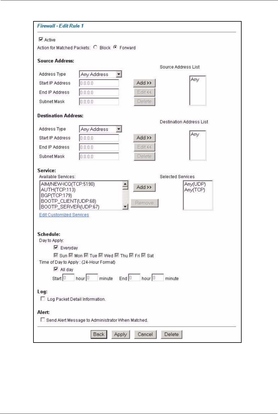
Figure 53 Firewall: Edit Rule
The following table describes the labels in this screen.

P-660H/HW/W-T Series User’ Guide
Chapter 11 Firewall Configuration 140
Table 39 Firewall: Edit Rule
LABEL DESCRIPTION
Active Select this option to enable this firewall rule.
Action for Matched
Packet
Use the radio button to select whether to discard (Block) or allow the passage of
(Forward) packets that match this rule.
Source/Destination
Address
Address Type Do you want your rule to apply to packets with a particular (single) IP, a range of
IP addresses (e.g., 192.168.1.10 to 192.169.1.50), a subnet or any IP address?
Select an option from the drop-down list box that includes: Single Address,
Range Address, Subnet Address and Any Address.
Start IP Address Enter the single IP address or the starting IP address in a range here.
End IP Address Enter the ending IP address in a range here.
Subnet Mask Enter the subnet mask here, if applicable.
Add Click Add to add a new address to the Source or Destination Address box.
You can add multiple addresses, ranges of addresses, and/or subnets.
Edit To edit an existing source or destination address, select it from the box and click
Edit.
Delete Highlight an existing source or destination address from the Source or
Destination Address box above and click Delete to remove it.
Services
Available/ Selected
Services
Please see Section 11.10 on page 146 for more information on services
available. Highlight a service from the Available Services box on the left, then
click Add>> to add it to the Selected Services box on the right. To remove a
service, highlight it in the Selected Services box on the right, then click
Remove.
Edit Customized
Service
Click the Edit Customized Services link to bring up the screen that you use to
configure a new custom service that is not in the predefined list of services.
Schedule
Day to Apply Select everyday or the day(s) of the week to apply the rule.
Time of Day to
Apply (24-Hour
Format)
Select All Day or enter the start and end times in the hour-minute format to
apply the rule.
Log
Log Packet Detail
Information
This field determines if a log for packets that match the rule is created (Enable)
or not (Disable). Go to the Log Settings page and select the Access Control
logs category to have the Prestige record these logs.
Alert
Send Alert Message
to Administrator
When Matched
Select the check box to have the Prestige generate an alert when the rule is
matched.
Back Click Back to return to the previous screen.
Apply Click Apply to save your customized settings and exit this screen.
Cancel Click Cancel to exit this screen without saving.
Delete Click Delete to remove this firewall rule and return to the Firewall Rule
Summary screen.
P-660H/HW/W-T Series User’ Guide
141 Chapter 11 Firewall Configuration
11.7 Customized Services
Configure customized services and port numbers not predefined by the Prestige. For a
comprehensive list of port numbers and services, visit the IANA (Internet Assigned Number
Authority) website. For further information on these services, please read Section 11.10 on
page 146. Click the Customized Services link while editing a firewall rule to configure a
custom service port. This displays the following screen.
Refer to Section 10.1 on page 118 for more information.
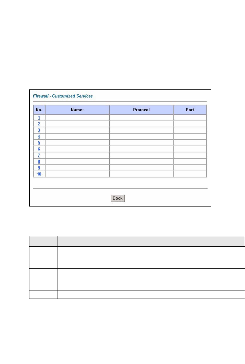
Figure 54 Firewall: Customized Services
The following table describes the labels in this screen.
11.8 Configuring A Customized Service
Click a rule number in the Firewall Customized Services screen to create a new custom port
or edit an existing one. This action displays the following screen.
Table 40 Customized Services
LABEL DESCRIPTION
No. This is the number of your customized port. Click a rule’s number of a service to go to the
Firewall Customized Services Config screen to configure or edit a customized service.
Name This is the name of your customized service.
Protocol This shows the IP protocol (TCP, UDP or TCP/UDP) that defines your customized
service.
Port This is the port number or range that defines your customized service.
Back Click Back to return the Firewall Edit Rule screen.
P-660H/HW/W-T Series User’ Guide
Chapter 11 Firewall Configuration 142
Refer to Section 10.1 on page 118 for more information.
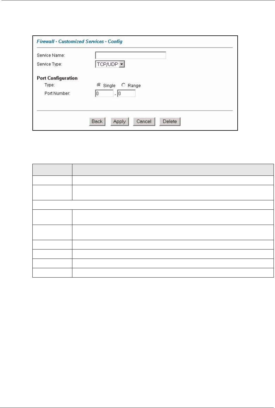
Figure 55 Firewall: Configure Customized Services
The following table describes the labels in this screen.
11.9 Example Firewall Rule
The following Internet firewall rule example allows a hypothetical “My Service” connection
from the Internet.
1Click Firewall in the navigation panel and click Rule Summary.
2Select WAN to LAN in the Packet Direction field.
Table 41 Firewall: Configure Customized Services
LABEL DESCRIPTION
Service Name Type a unique name for your custom port.
Service Type Choose the IP port (TCP, UDP or TCP/UDP) that defines your customized port from
the drop down list box.
Port Configuration
Type Click Single to specify one port only or Range to specify a span of ports that define
your customized service.
Port Number Type a single port number or the range of port numbers that define your customized
service.
Back Click Back to return to the Firewall Customized Services screen.
Apply Click Apply to save your customized settings and exit this screen.
Cancel Click Cancel to return to the previously saved settings.
Delete Click Delete to delete the current rule.
P-660H/HW/W-T Series User’ Guide
143 Chapter 11 Firewall Configuration
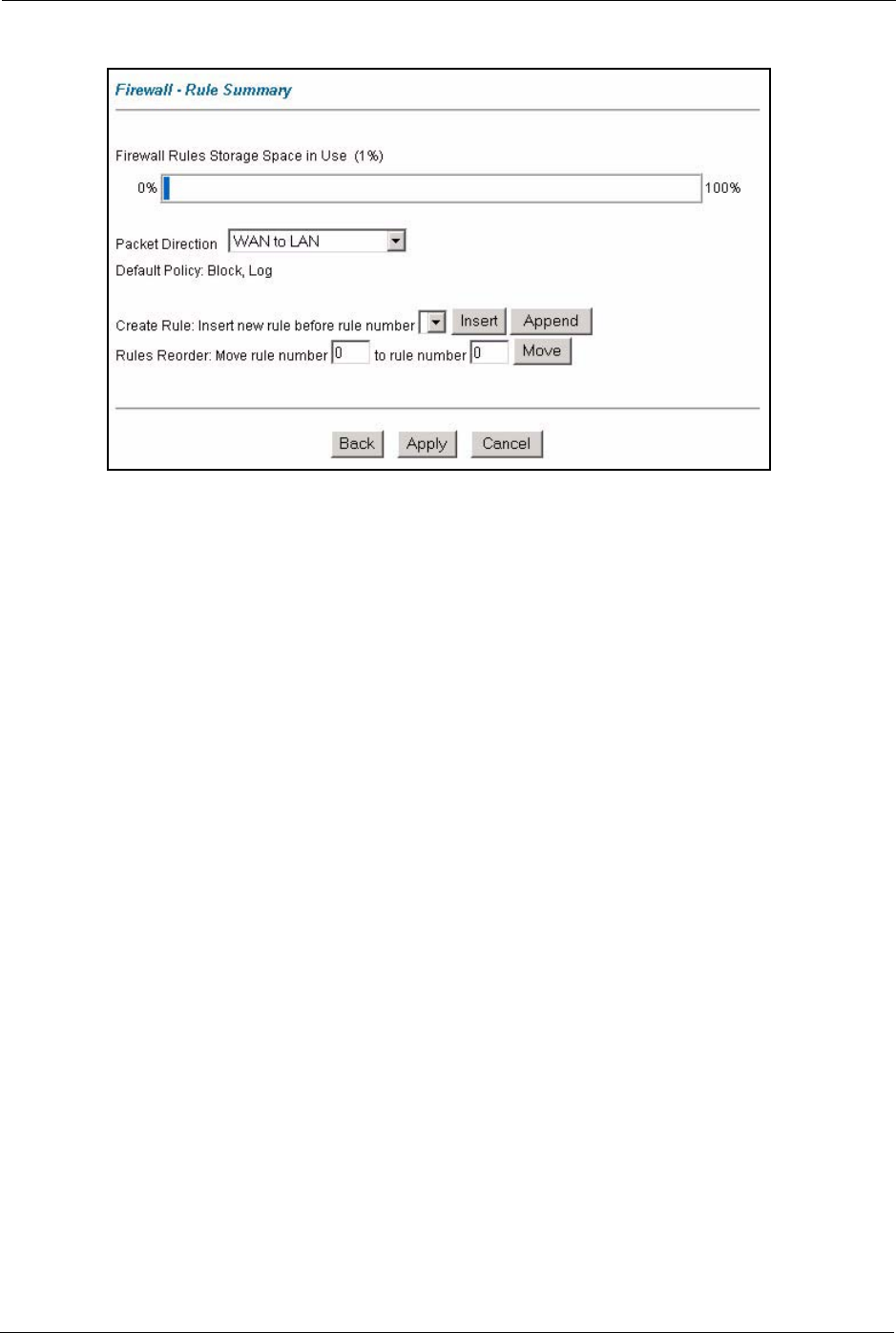
Figure 56 Firewall Example: Rule Summary
3In the Rule Summary screen, type the index number for where you want to put the rule.
For example, if you type “6”, your new rule becomes number 6 and the previous rule 6 (if
there is one) becomes rule 7.
4Click Insert to display the firewall rule configuration screen.
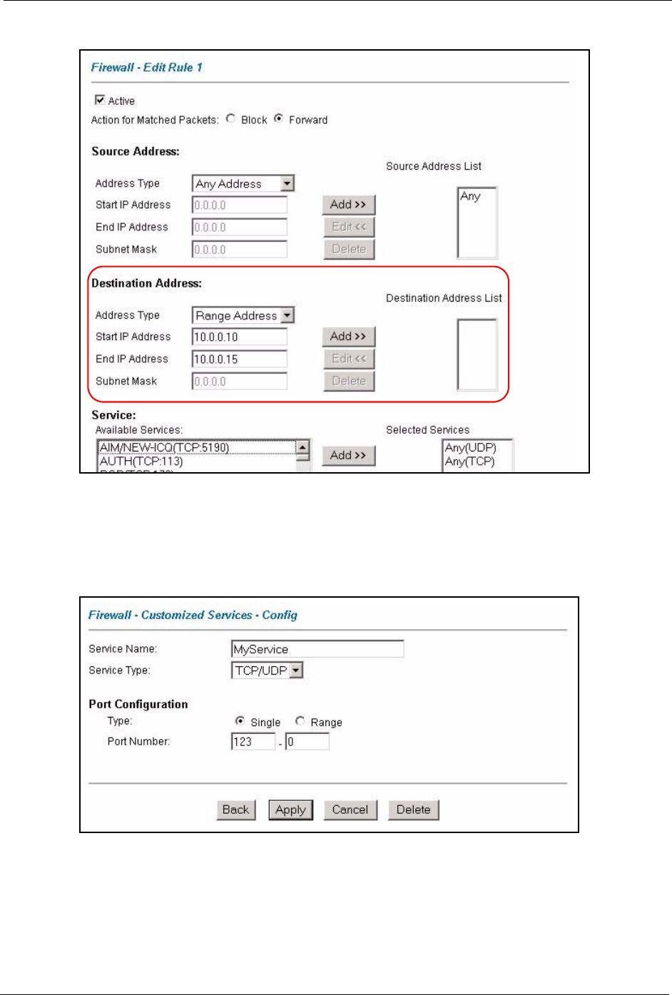
5Select Any in the Destination Address box and then click Delete.
6Configure the destination address screen as follows and click Add.
P-660H/HW/W-T Series User’ Guide
Chapter 11 Firewall Configuration 144
Figure 57 Firewall Example: Edit Rule: Destination Address
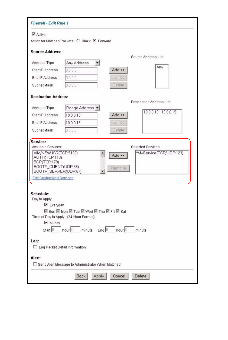
7In the Edit Rule screen, click the Customized Services link to open the Customized
Service screen.
8Click an index number to display the Customized Services -Config screen and configure
the screen as follows and click Apply.
Figure 58 Edit Custom Port Example
9In the Edit Rule screen, use the Add>> and Remove buttons between Available
Services and Selected Services list boxes to configure it as follows. Click Apply when
you are done.
P-660H/HW/W-T Series User’ Guide
145 Chapter 11 Firewall Configuration
Figure 59 Firewall Example: Edit Rule: Select Customized Services
Note: Custom ports show up with an “*” before their names in the Services list box
and the Rule Summary list box. Click Apply after you’ve created your custom
port.
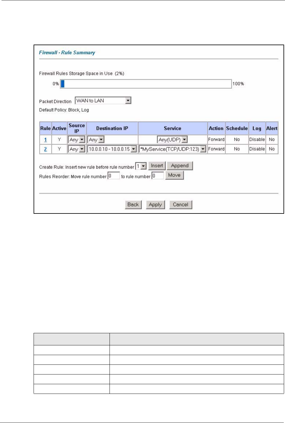
On completing the configuration procedure for this Internet firewall rule, the Rule Summary
screen should look like the following.
P-660H/HW/W-T Series User’ Guide
Chapter 11 Firewall Configuration 146
Rule 2 allows a “My Service” connection from the WAN to IP addresses 10.0.0.10 through
10.0.0.15 on the LAN.
Figure 60 Firewall Example: Rule Summary: My Service
11.10 Predefined Services
The Available Services list box in the Edit Rule screen (see Section 11.6.1 on page 138)
displays all predefined services that the Prestige already supports. Next to the name of the
service, two fields appear in brackets. The first field indicates the IP protocol type (TCP, UDP,
or ICMP). The second field indicates the IP port number that defines the service. (Note that
there may be more than one IP protocol type. For example, look at the default configuration
labeled “(DNS)”. (UDP/TCP:53) means UDP port 53 and TCP port 53. Up to 128 entries are
supported. Custom service ports may also be configured using the Edit Customized Services
function discussed previously.
Table 42 Predefined Services
SERVICE DESCRIPTION
AIM/NEW_ICQ(TCP:5190) AOL’s Internet Messenger service, used as a listening port by ICQ.
AUTH(TCP:113) Authentication protocol used by some servers.
BGP(TCP:179) Border Gateway Protocol.
BOOTP_CLIENT(UDP:68) DHCP Client.
BOOTP_SERVER(UDP:67) DHCP Server.

P-660H/HW/W-T Series User’ Guide
147 Chapter 11 Firewall Configuration
CU-SEEME(TCP/UDP:7648,
24032)
A popular videoconferencing solution from White Pines Software.
DNS(UDP/TCP:53) Domain Name Server, a service that matches web names (e.g.
www.zyxel.com) to IP numbers.
FINGER(TCP:79) Finger is a UNIX or Internet related command that can be used to find
out if a user is logged on.
FTP(TCP:20.21) File Transfer Program, a program to enable fast transfer of files,
including large files that may not be possible by e-mail.
H.323(TCP:1720) Net Meeting uses this protocol.
HTTP(TCP:80) Hyper Text Transfer Protocol - a client/server protocol for the world
wide web.
HTTPS HTTPS is a secured http session often used in e-commerce.
ICQ(UDP:4000) This is a popular Internet chat program.
IPSEC_TRANSPORT/
TUNNEL(AH:0)
The IPSEC AH (Authentication Header) tunneling protocol uses this
service.
IPSEC_TUNNEL(ESP:0) The IPSEC ESP (Encapsulation Security Protocol) tunneling protocol
uses this service.
IRC(TCP/UDP:6667) This is another popular Internet chat program.
MSN Messenger(TCP:1863) Microsoft Networks’ messenger service uses this protocol.
MULTICAST(IGMP:0) Internet Group Multicast Protocol is used when sending packets to a
specific group of hosts.
NEWS(TCP:144) A protocol for news groups.
NFS(UDP:2049) Network File System - NFS is a client/server distributed file service that
provides transparent file-sharing for network environments.
NNTP(TCP:119) Network News Transport Protocol is the delivery mechanism for the
USENET newsgroup service.
PING(ICMP:0) Packet INternet Groper is a protocol that sends out ICMP echo
requests to test whether or not a remote host is reachable.
POP3(TCP:110) Post Office Protocol version 3 lets a client computer get e-mail from a
POP3 server through a temporary connection (TCP/IP or other).
PPTP(TCP:1723) Point-to-Point Tunneling Protocol enables secure transfer of data over
public networks. This is the control channel.
PPTP_TUNNEL(GRE:0) Point-to-Point Tunneling Protocol enables secure transfer of data over
public networks. This is the data channel.
RCMD(TCP:512) Remote Command Service.
REAL_AUDIO(TCP:7070) A streaming audio service that enables real time sound over the web.
REXEC(TCP:514) Remote Execution Daemon.
RLOGIN(TCP:513) Remote Login.
RTELNET(TCP:107) Remote Telnet.
RTSP(TCP/UDP:554) The Real Time Streaming (media control) Protocol (RTSP) is a remote
control for multimedia on the Internet.
SFTP(TCP:115) Simple File Transfer Protocol.
Table 42 Predefined Services (continued)
SERVICE DESCRIPTION
P-660H/HW/W-T Series User’ Guide
Chapter 11 Firewall Configuration 148
11.11 Anti-Probing
If an outside user attempts to probe an unsupported port on your Prestige, an ICMP response
packet is automatically returned. This allows the outside user to know the Prestige exists. The
Prestige supports anti-probing, which prevents the ICMP response packet from being sent.
This keeps outsiders from discovering your Prestige when unsupported ports are probed.
Internet Control Message Protocol (ICMP) is a message control and error-reporting protocol
between a host server and a gateway to the Internet. ICMP uses Internet Protocol (IP)
datagrams, but the messages are processed by the TCP/IP software and directly apparent to the
application user.
Refer to Section 10.1 on page 118 for more information.
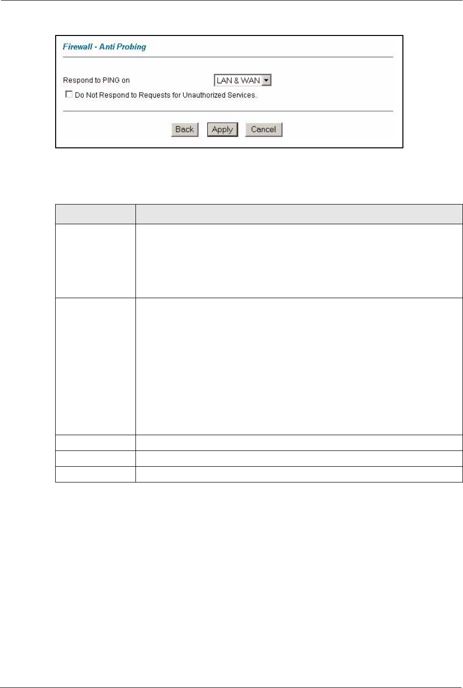
Click Firewall in the navigation panel and click Anti Probing to display the screen as shown.
SMTP(TCP:25) Simple Mail Transfer Protocol is the message-exchange standard for
the Internet. SMTP enables you to move messages from one e-mail
server to another.
SNMP(TCP/UDP:161) Simple Network Management Program.
SNMP-TRAPS (TCP/
UDP:162)
Traps for use with the SNMP (RFC:1215).
SQL-NET(TCP:1521) Structured Query Language is an interface to access data on many
different types of database systems, including mainframes, midrange
systems, UNIX systems and network servers.
SSDP(UDP:1900) Simole Service Discovery Protocol (SSDP) is a discovery service
searching for Universal Plug and Play devices on your home network
or upstream Internet gateways using DUDP port 1900.
SSH(TCP/UDP:22) Secure Shell Remote Login Program.
STRMWORKS(UDP:1558) Stream Works Protocol.
SYSLOG(UDP:514) Syslog allows you to send system logs to a UNIX server.
TACACS(UDP:49) Login Host Protocol used for (Terminal Access Controller Access
Control System).
TELNET(TCP:23) Telnet is the login and terminal emulation protocol common on the
Internet and in UNIX environments. It operates over TCP/IP networks.
Its primary function is to allow users to log into remote host systems.
TFTP(UDP:69) Trivial File Transfer Protocol is an Internet file transfer protocol similar
to FTP, but uses the UDP (User Datagram Protocol) rather than TCP
(Transmission Control Protocol).
VDOLIVE(TCP:7000) Another videoconferencing solution.
Table 42 Predefined Services (continued)
SERVICE DESCRIPTION
P-660H/HW/W-T Series User’ Guide
149 Chapter 11 Firewall Configuration
Figure 61 Firewall: Anti Probing
The following table describes the labels in this screen.
11.12 DoS Thresholds
For DoS attacks, the Prestige uses thresholds to determine when to drop sessions that do not
become fully established. These thresholds apply globally to all sessions.
You can use the default threshold values, or you can change them to values more suitable to
your security requirements.
Refer to Section 11.12.3 on page 151 to configure thresholds.
Table 43 Firewall: Anti Probing
LABEL DESCRIPTION
Respond to PING
on
The Prestige does not respond to any incoming Ping requests when Disable is
selected.
Select LAN to reply to incoming LAN Ping requests.
Select WAN to reply to incoming WAN Ping requests.
Otherwise select LAN & WAN to reply to both incoming LAN and WAN Ping
requests.
Do not respond to
requests for
unauthorized
services.
Select this option to prevent hackers from finding the Prestige by probing for
unused ports. If you select this option, the Prestige will not respond to port
request(s) for unused ports, thus leaving the unused ports and the Prestige
unseen. By default this option is not selected and the Prestige will reply with an
ICMP Port Unreachable packet for a port probe on its unused UDP ports, and a
TCP Reset packet for a port probe on its unused TCP ports.
Note that the probing packets must first traverse the Prestige 's firewall
mechanism before reaching this anti-probing mechanism. Therefore if the firewall
mechanism blocks a probing packet, the Prestige reacts based on the firewall
policy, which by default, is to send a TCP reset packet for a blocked TCP packet.
You can use the command "sys firewall tcprst rst [on|off]" to change this policy.
When the firewall mechanism blocks a UDP packet, it drops the packet without
sending a response packet.
Back Click Back to return to the previous screen.
Apply Click Apply to save your changes back to the Prestige.
Reset Click Reset to begin configuring this screen afresh.

P-660H/HW/W-T Series User’ Guide
Chapter 11 Firewall Configuration 150
11.12.1 Threshold Values
Tune these parameters when something is not working and after you have checked the firewall
counters. These default values should work fine for most small offices. Factors influencing
choices for threshold values are:
• The maximum number of opened sessions.
• The minimum capacity of server backlog in your LAN network.
• The CPU power of servers in your LAN network.
• Network bandwidth.
• Type of traffic for certain servers.
If your network is slower than average for any of these factors (especially if you have servers
that are slow or handle many tasks and are often busy), then the default values should be
reduced.
You should make any changes to the threshold values before you continue configuring
firewall rules.
11.12.2 Half-Open Sessions
An unusually high number of half-open sessions (either an absolute number or measured as
the arrival rate) could indicate that a Denial of Service attack is occurring. For TCP, "half-
open" means that the session has not reached the established state-the TCP three-way
handshake has not yet been completed (see Figure 47 on page 122). For UDP, "half-open"
means that the firewall has detected no return traffic.
The Prestige measures both the total number of existing half-open sessions and the rate of
session establishment attempts. Both TCP and UDP half-open sessions are counted in the total
number and rate measurements. Measurements are made once a minute.
When the number of existing half-open sessions rises above a threshold (max-incomplete
high), the Prestige starts deleting half-open sessions as required to accommodate new
connection requests. The Prestige continues to delete half-open requests as necessary, until the
number of existing half-open sessions drops below another threshold (max-incomplete low).
When the rate of new connection attempts rises above a threshold (one-minute high), the
Prestige starts deleting half-open sessions as required to accommodate new connection
requests. The Prestige continues to delete half-open sessions as necessary, until the rate of new
connection attempts drops below another threshold (one-minute low). The rate is the number
of new attempts detected in the last one-minute sample period.
11.12.2.1 TCP Maximum Incomplete and Blocking Time
An unusually high number of half-open sessions with the same destination host address could
indicate that a Denial of Service attack is being launched against the host.
P-660H/HW/W-T Series User’ Guide
151 Chapter 11 Firewall Configuration
Whenever the number of half-open sessions with the same destination host address rises above
a threshold (TCP Maximum Incomplete), the Prestige starts deleting half-open sessions
according to one of the following methods:
• If the Blocking Time timeout is 0 (the default), then the Prestige deletes the oldest
existing half-open session for the host for every new connection request to the host. This
ensures that the number of half-open sessions to a given host will never exceed the
threshold.
• If the Blocking Time timeout is greater than 0, then the Prestige blocks all new
connection requests to the host giving the server time to handle the present connections.
The Prestige continues to block all new connection requests until the Blocking Time
expires.
11.12.3 Configuring Firewall Thresholds
The Prestige also sends alerts whenever TCP Maximum Incomplete is exceeded. The global
values specified for the threshold and timeout apply to all TCP connections.
Click Firewall, and Threshold to bring up the next screen.
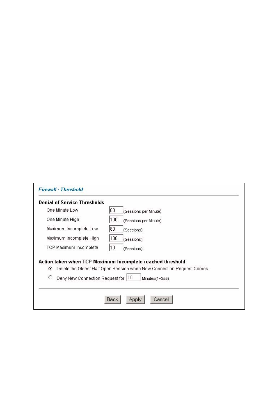
Figure 62 Firewall: Threshold
The following table describes the labels in this screen.

P-660H/HW/W-T Series User’ Guide
Chapter 11 Firewall Configuration 152
Table 44 Firewall: Threshold
LABEL DESCRIPTION DEFAULT VALUES
Denial of Service
Thresholds
One Minute Low This is the rate of new half-open sessions that
causes the firewall to stop deleting half-open
sessions. The Prestige continues to delete
half-open sessions as necessary, until the
rate of new connection attempts drops below
this number.
80 existing half-open sessions.
One Minute High This is the rate of new half-open sessions that
causes the firewall to start deleting half-open
sessions. When the rate of new connection
attempts rises above this number, the
Prestige deletes half-open sessions as
required to accommodate new connection
attempts.
100 half-open sessions per minute.
The above numbers cause the
Prestige to start deleting half-open
sessions when more than 100
session establishment attempts
have been detected in the last
minute, and to stop deleting half-
open sessions when fewer than 80
session establishment attempts
have been detected in the last
minute.
Maximum
Incomplete Low
This is the number of existing half-open
sessions that causes the firewall to stop
deleting half-open sessions. The Prestige
continues to delete half-open requests as
necessary, until the number of existing half-
open sessions drops below this number.
80 existing half-open sessions.
Maximum
Incomplete High
This is the number of existing half-open
sessions that causes the firewall to start
deleting half-open sessions. When the
number of existing half-open sessions rises
above this number, the Prestige deletes half-
open sessions as required to accommodate
new connection requests. Do not set
Maximum Incomplete High to lower than the
current Maximum Incomplete Low number.
100 existing half-open sessions.
The above values causes the
Prestige to start deleting half-open
sessions when the number of
existing half-open sessions rises
above 100, and to stop deleting
half-open sessions with the
number of existing half-open
sessions drops below 80.
TCP Maximum
Incomplete
This is the number of existing half-open TCP
sessions with the same destination host IP
address that causes the firewall to start
dropping half-open sessions to that same
destination host IP address. Enter a number
between 1 and 256. As a general rule, you
should choose a smaller number for a smaller
network, a slower system or limited
bandwidth.
30 existing half-open TCP
sessions.
Action taken when the TCP Maximum Incomplete threshold is reached.
Delete the oldest
half open session
when new
connection
request comes
Select this radio button to clear the oldest half
open session when a new connection request
comes.

P-660H/HW/W-T Series User’ Guide
153 Chapter 11 Firewall Configuration
Deny new
connection
request for
Select this radio button and specify for how
long the Prestige should block new
connection requests when TCP Maximum
Incomplete is reached.
Enter the length of blocking time in minutes
(between 1 and 256).
Back Click Back to return to the previous screen.
Apply Click Apply to save your changes back to the Prestige.
Cancel Click Cancel to begin configuring this screen afresh.
Table 44 Firewall: Threshold (continued)
LABEL DESCRIPTION DEFAULT VALUES
P-660H/HW/W-T Series User’ Guide
Chapter 12 Content Filtering 154
CHAPTER 12
Content Filtering
This chapter covers how to configure content filtering.
12.1 Content Filtering Overview
Internet content filtering allows you to create and enforce Internet access policies tailored to
your needs. Content filtering gives you the ability to block web sites that contain key words
(that you specify) in the URL. You can set a schedule for when the Prestige performs content
filtering. You can also specify trusted IP addresses on the LAN for which the Prestige will not
perform content filtering.
12.2 The Main Content Filter Screen
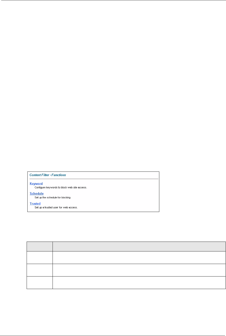
Click Content Filter to display the main Content Filtering screen.
Figure 63 Content Filtering
The following table describes the links in this screen.
Table 45
LINK DESCRIPTION
Keyword Click this link to display a screen where you can configure your Prestige to block Web
sites containing keywords in their URLs,
Schedule Click this link to display a screen where you can set the days and times for the Prestige to
perform content filtering,
Trusted Click this link to display a screen where you can exclude a range of users on the LAN
from content filtering on your Prestige
P-660H/HW/W-T Series User’ Guide
155 Chapter 12 Content Filtering
12.3 Configuring Keyword Blocking
Use this screen to block sites containing certain keywords in the URL. For example, if you
enable the keyword "bad", the Prestige blocks all sites containing this keyword including the
URL http://www.website.com/bad.html, even if it is not included in the Filter List.
To have your Prestige block Web sites containing keywords in their URLs, click Content
Filter and Keyword. The screen appears as shown.
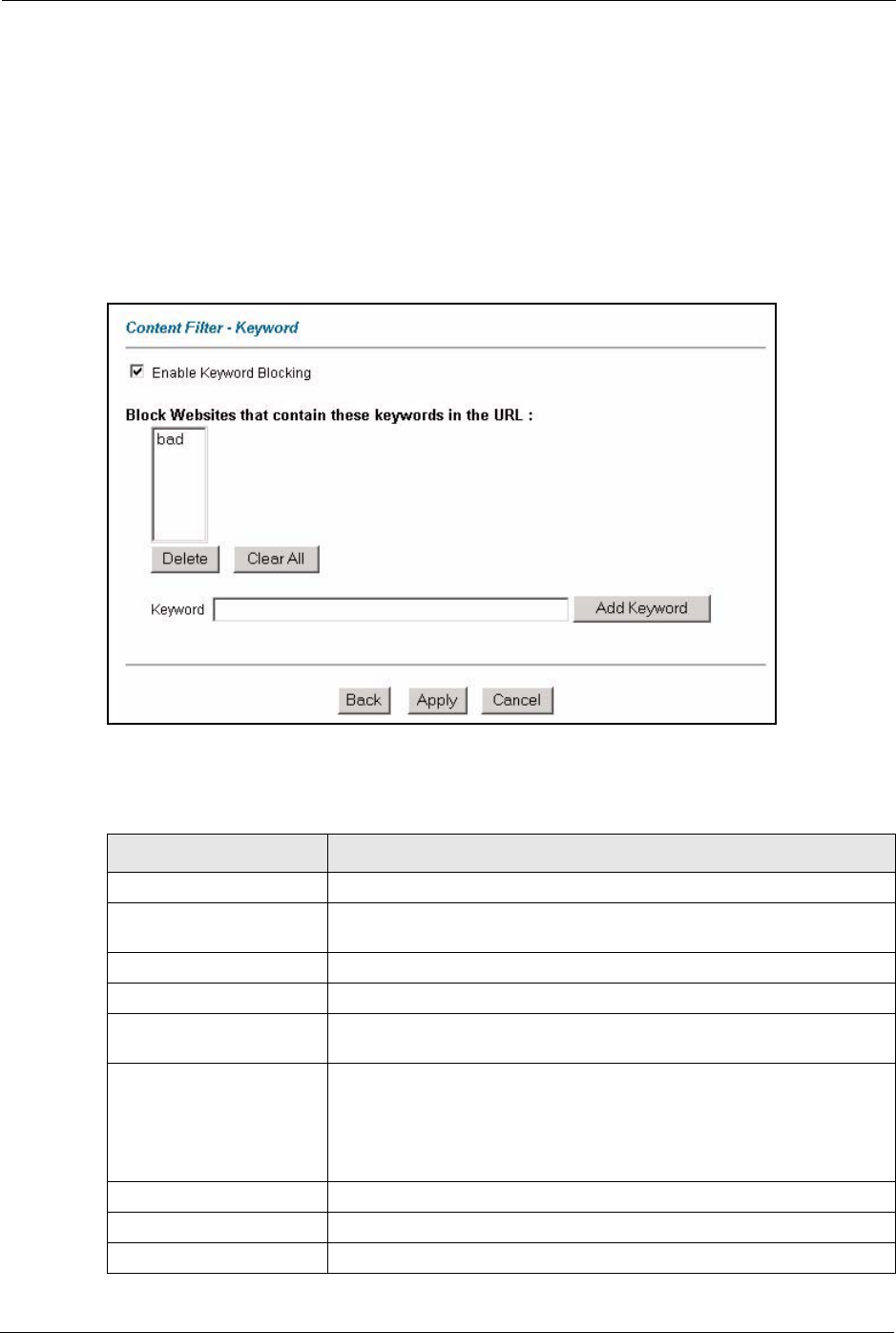
Figure 64 Content Filter: Keyword
The following table describes the labels in this screen.
Table 46 Content Filter: Keyword
LABEL DESCRIPTION
Enable Keyword Blocking Select this check box to enable this feature.
Block Websites that contain
these keywords in the URL:
This box contains the list of all the keywords that you have configured the
Prestige to block.
Delete Highlight a keyword in the box and click Delete to remove it.
Clear All Click Clear All to remove all of the keywords from the list.
Keyword Type a keyword in this field. You may use any character (up to 127
characters). Wildcards are not allowed.
Add Keyword Click Add Keyword after you have typed a keyword.
Repeat this procedure to add other keywords. Up to 64 keywords are
allowed.
When you try to access a web page containing a keyword, you will get a
message telling you that the content filter is blocking this request.
Back Click Back to return to the previous screen.
Apply Click Apply to save your changes back to the Prestige.
Cancel Click Cancel to return to the previously saved settings.
P-660H/HW/W-T Series User’ Guide
Chapter 12 Content Filtering 156
12.4 Configuring the Schedule
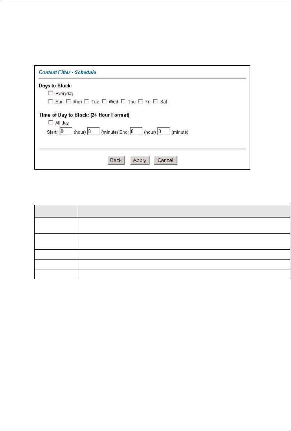
To set the days and times for the Prestige to perform content filtering, click Content Filter
and Schedule. The screen appears as shown.
Figure 65 Content Filter: Schedule
The following table describes the labels in this screen.
12.5 Configuring Trusted Computers
To exclude a range of users on the LAN from content filtering on your Prestige, click Content
Filter and Trusted. The screen appears as shown.
Table 47 Content Filter: Schedule
LABEL DESCRIPTION
Days to Block: Select a check box to configure which days of the week (or everyday) you want the
content filtering to be active.
Time of Day to
Block:
Use the 24 hour format to configure which time of the day (or select the All day check
box) you want the content filtering to be active.
Back Click Back to return to the previous screen.
Apply Click Apply to save your changes.
Cancel Click Cancel to return to the previously saved settings.
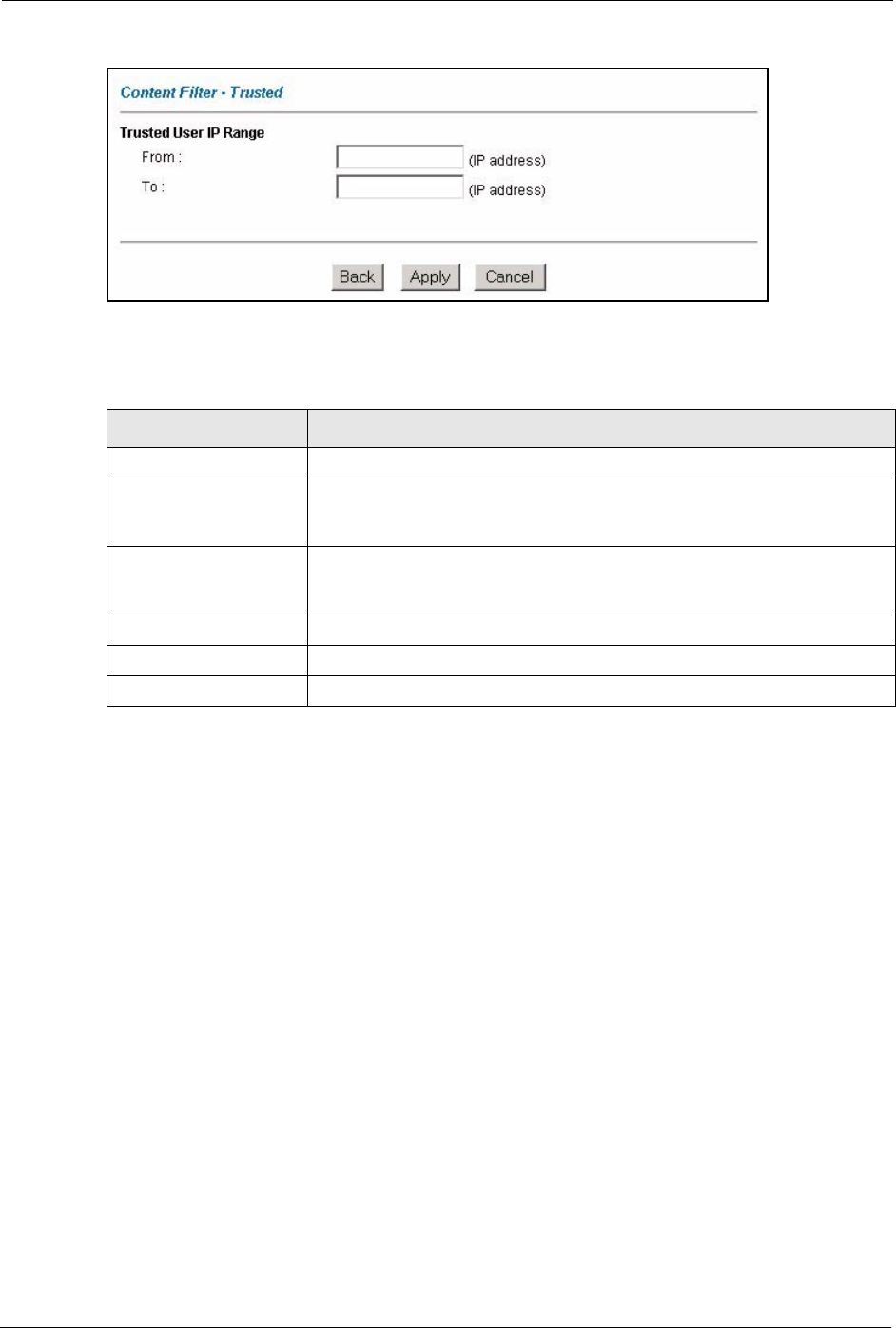
P-660H/HW/W-T Series User’ Guide
157 Chapter 12 Content Filtering
Figure 66 Content Filter: Trusted
The following table describes the labels in this screen.
Table 48 Content Filter: Trusted
LABEL DESCRIPTION
Trusted User IP Range
From Type the IP address of a computer (or the beginning IP address of a specific
range of computers) on the LAN that you want to exclude from content
filtering.
To Type the ending IP address of a specific range of users on your LAN that
you want to exclude from content filtering. Leave this field blank if you want
to exclude an individual computer.
Back Click Back to return to the previous screen.
Apply Click Apply to save your changes back to the Prestige.
Cancel Click Cancel to return to the previously saved settings.

P-660H/HW/W-T Series User’ Guide
Chapter 13 Remote Management Configuration 158
CHAPTER 13
Remote Management
Configuration
This chapter provides information on configuring remote management.
13.1 Remote Management Overview
Remote management allows you to determine which services/protocols can access which
Prestige interface (if any) from which computers.
When you configure remote management to allow management from the WAN, you still need
to configure a firewall rule to allow access.
You may manage your Prestige from a remote location via:
• Internet (WAN only)
• ALL (LAN and WAN)
• LAN only,
• Neither (Disable).
When you Choose WAN o n ly or ALL (LAN & WAN), you still need to configure a firewall
rule to allow access.
To disable remote management of a service, select Disable in the corresponding Server
Access field.
You may only have one remote management session running at a time. The Prestige
automatically disconnects a remote management session of lower priority when another
remote management session of higher priority starts. The priorities for the different types of
remote management sessions are as follows.
1Telnet
2HTTP
13.1.1 Remote Management Limitations
Remote management over LAN or WAN will not work when:
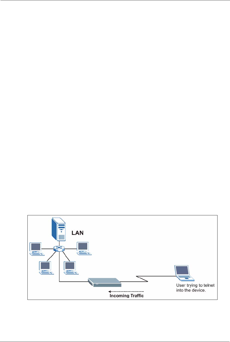
P-660H/HW/W-T Series User’ Guide
159 Chapter 13 Remote Management Configuration
• A filter in SMT menu 3.1 (LAN) or in menu 11.5 (WAN) is applied to block a Telnet,
FTP or Web service.
• You have disabled that service in one of the remote management screens.
• The IP address in the Secured Client IP field does not match the client IP address. If it
does not match, the Prestige will disconnect the session immediately.
• There is already another remote management session with an equal or higher priority
running. You may only have one remote management session running at one time.
• There is a firewall rule that blocks it.
13.1.2 Remote Management and NAT
When NAT is enabled:
• Use the Prestige’s WAN IP address when configuring from the WAN.
• Use the Prestige’s LAN IP address when configuring from the LAN.
13.1.3 System Timeout
There is a default system management idle timeout of five minutes (three hundred seconds).
The Prestige automatically logs you out if the management session remains idle for longer
than this timeout period. The management session does not time out when a statistics screen is
polling.
13.2 Telnet
You can configure your Prestige for remote Telnet access as shown next.
Figure 67 Telnet Configuration on a TCP/IP Network
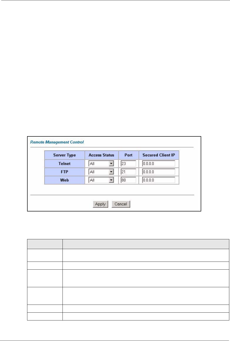
P-660H/HW/W-T Series User’ Guide
Chapter 13 Remote Management Configuration 160
13.3 FTP
You can upload and download Prestige firmware and configuration files using FTP. To use this
feature, your computer must have an FTP client.
13.4 Web
You can use the Prestige’s embedded web configurator for configuration and file
management. See the online help for details.
13.5 Configuring Remote Management
Click Remote Management to open the following screen. See Section 13.1 on page 158 for
more information.
Figure 68 Remote Management
The following table describes the fields in this screen.
Table 49 Remote Management
LABEL DESCRIPTION
Server Type Each of these labels denotes a service that you may use to remotely manage the
Prestige.
Access Status Select the access interface. Choices are All, LAN Only, WAN Only and Disable.
Port This field shows the port number for the remote management service. You may
change the port number for a service in this field, but you must use the same port
number to use that service for remote management.
Secured Client
IP
The default 0.0.0.0 allows any client to use this service to remotely manage the
Prestige. Type an IP address to restrict access to a client with a matching IP
address.
Apply Click Apply to save your settings back to the Prestige.
Cancel Click Cancel to begin configuring this screen afresh.

P-660H/HW/W-T Series User’ Guide
161 Chapter 13 Remote Management Configuration

P-660H/HW/W-T Series User’ Guide
Chapter 14 Universal Plug-and-Play (UPnP) 162
CHAPTER 14
Universal Plug-and-Play (UPnP)
This chapter introduces the UPnP feature in the web configurator.
14.1 Introducing Universal Plug and Play
Universal Plug and Play (UPnP) is a distributed, open networking standard that uses TCP/IP
for simple peer-to-peer network connectivity between devices. A UPnP device can
dynamically join a network, obtain an IP address, convey its capabilities and learn about other
devices on the network. In turn, a device can leave a network smoothly and automatically
when it is no longer in use.
See Section 14.2.1 on page 163 for configuration instructions.
14.1.1 How do I know if I'm using UPnP?
UPnP hardware is identified as an icon in the Network Connections folder (Windows XP).
Each UPnP compatible device installed on your network will appear as a separate icon.
Selecting the icon of a UPnP device will allow you to access the information and properties of
that device.
14.1.2 NAT Traversal
UPnP NAT traversal automates the process of allowing an application to operate through
NAT. UPnP network devices can automatically configure network addressing, announce their
presence in the network to other UPnP devices and enable exchange of simple product and
service descriptions. NAT traversal allows the following:
• Dynamic port mapping
• Learning public IP addresses
• Assigning lease times to mappings
Windows Messenger is an example of an application that supports NAT traversal and UPnP.
See the NAT chapter for more information on NAT.
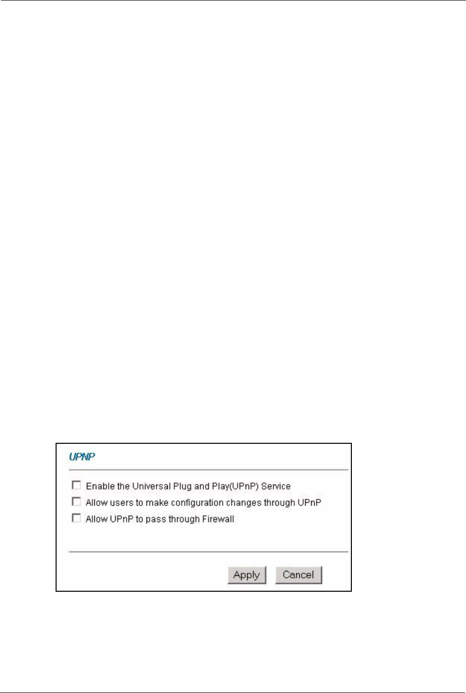
P-660H/HW/W-T Series User’ Guide
163 Chapter 14 Universal Plug-and-Play (UPnP)
14.1.3 Cautions with UPnP
The automated nature of NAT traversal applications in establishing their own services and
opening firewall ports may present network security issues. Network information and
configuration may also be obtained and modified by users in some network environments.
All UPnP-enabled devices may communicate freely with each other without additional
configuration. Disable UPnP if this is not your intention.
14.2 UPnP and ZyXEL
ZyXEL has achieved UPnP certification from the Universal Plug and Play Forum Creates
UPnP™ Implementers Corp. (UIC). ZyXEL's UPnP implementation supports IGD 1.0
(Internet Gateway Device). At the time of writing ZyXEL's UPnP implementation supports
Windows Messenger 4.6 and 4.7 while Windows Messenger 5.0 and Xbox are still being
tested.
UPnP broadcasts are only allowed on the LAN.
See later sections for examples of installing UPnP in Windows XP and Windows Me as well
as an example of using UPnP in Windows.
14.2.1 Configuring UPnP
From the Site Map in the main menu, click UPnP under Advanced Setup to display the
screen shown next.
See Section 14.1 on page 162 for more information.
Figure 69 Configuring UPnP
The following table describes the fields in this screen.
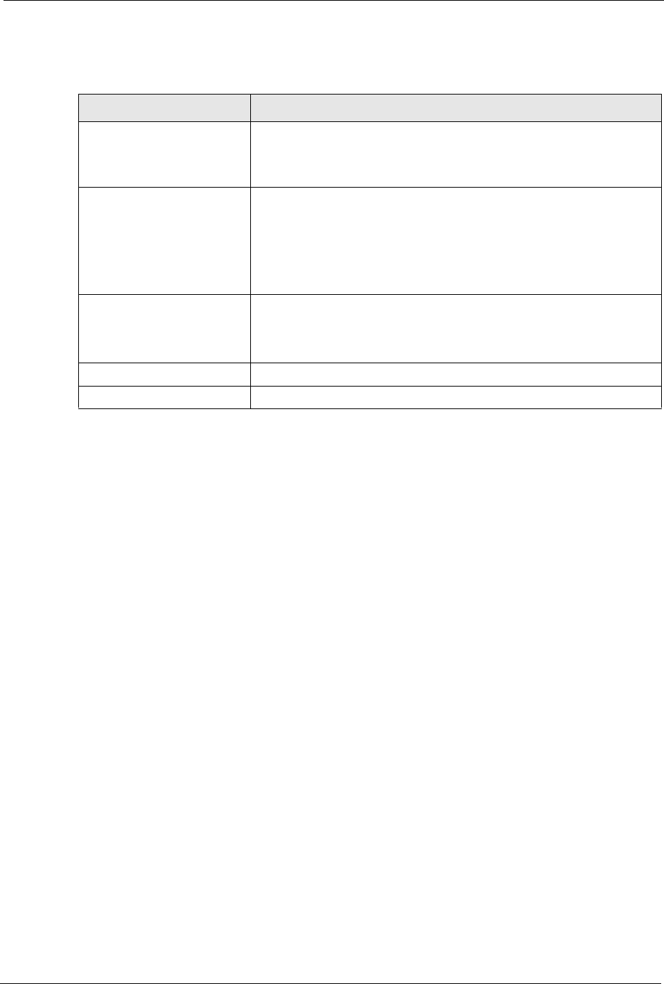
P-660H/HW/W-T Series User’ Guide
Chapter 14 Universal Plug-and-Play (UPnP) 164
14.3 Installing UPnP in Windows Example
This section shows how to install UPnP in Windows Me and Windows XP.
Installing UPnP in Windows Me
Follow the steps below to install the UPnP in Windows Me.
1Click Start and Control Panel. Double-click Add/Remove Programs.
2Click on the Windows Setup tab and select Communication in the Components
selection box. Click Details.
Table 50 Configuring UPnP
LABEL DESCRIPTION
Enable the Universal Plug
and Play (UPnP) Service
Select this check box to activate UPnP. Be aware that anyone could use
a UPnP application to open the web configurator's login screen without
entering the Prestige's IP address (although you must still enter the
password to access the web configurator).
Allow users to make
configuration changes
through UPnP
Select this check box to allow UPnP-enabled applications to
automatically configure the Prestige so that they can communicate
through the Prestige, for example by using NAT traversal, UPnP
applications automatically reserve a NAT forwarding port in order to
communicate with another UPnP enabled device; this eliminates the
need to manually configure port forwarding for the UPnP enabled
application.
Allow UPnP to pass through
Firewall
Select this check box to allow traffic from UPnP-enabled applications to
bypass the firewall.
Clear this check box to have the firewall block all UPnP application
packets (for example, MSN packets).
Apply Click Apply to save the setting to the Prestige.
Cancel Click Cancel to return to the previously saved settings.
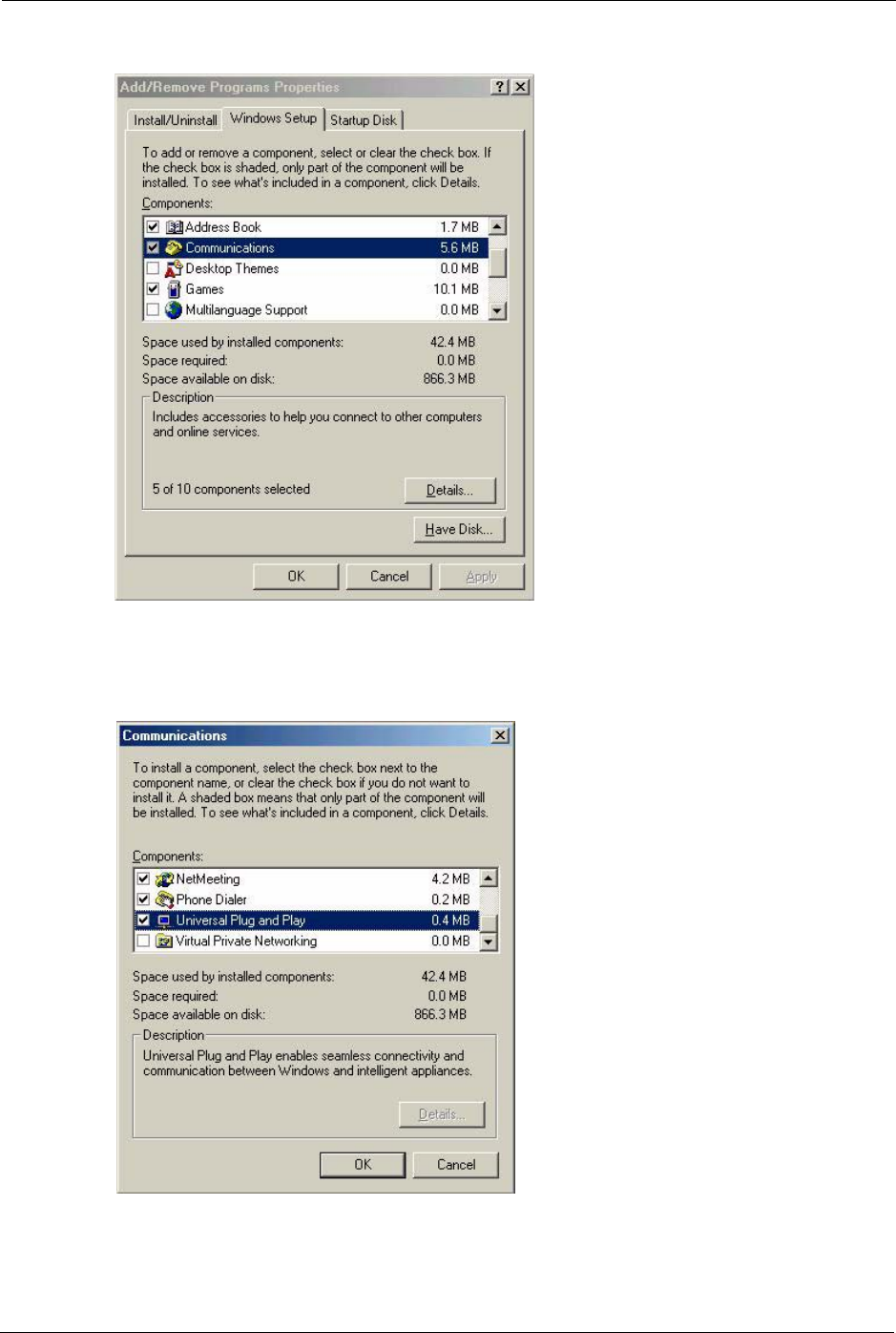
P-660H/HW/W-T Series User’ Guide
165 Chapter 14 Universal Plug-and-Play (UPnP)
Figure 70 Add/Remove Programs: Windows Setup: Communication
3In the Communications window, select the Universal Plug and Play check box in the
Components selection box.
Figure 71 Add/Remove Programs: Windows Setup: Communication: Components
4Click OK to go back to the Add/Remove Programs Properties window and click Next.
5Restart the computer when prompted.
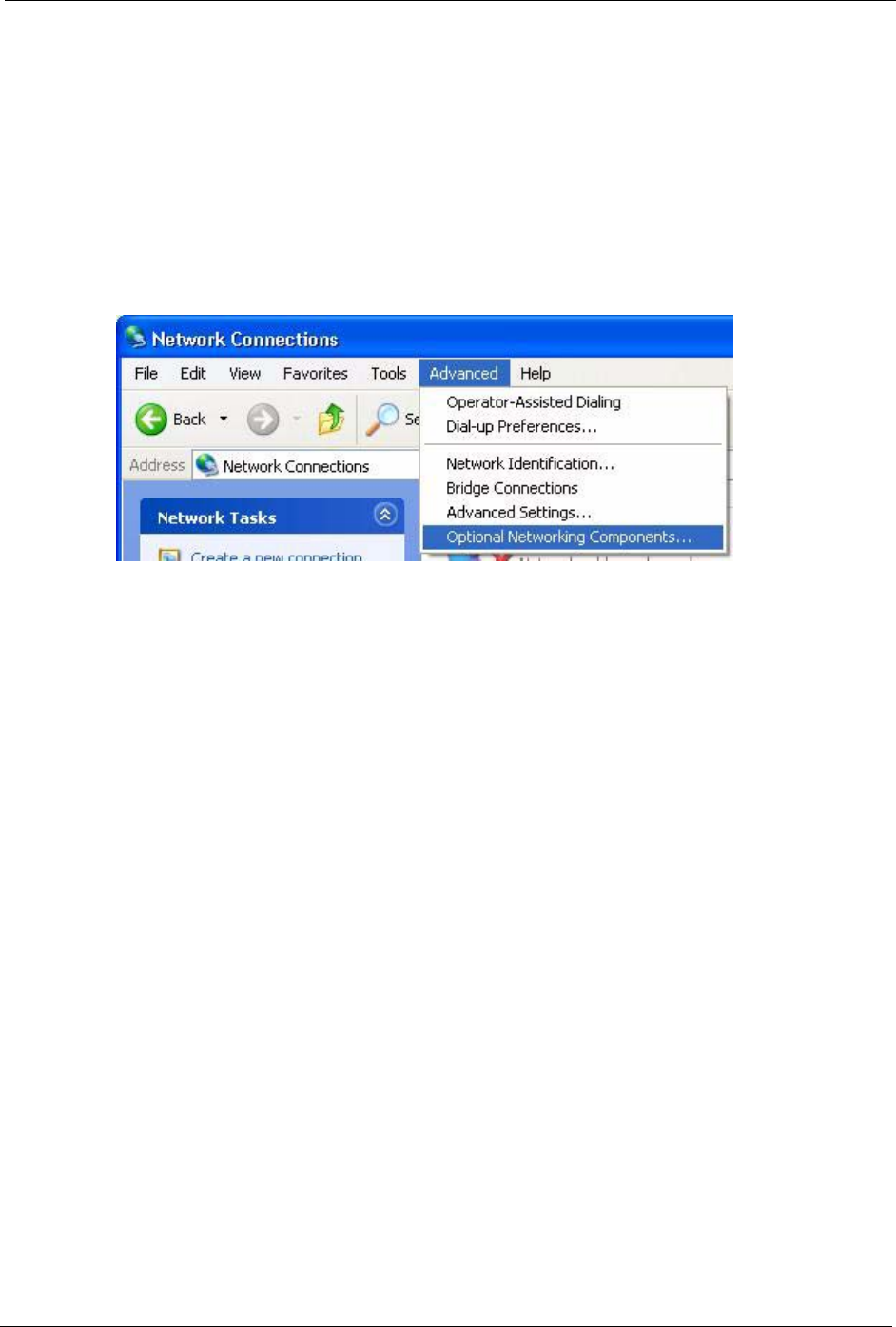
P-660H/HW/W-T Series User’ Guide
Chapter 14 Universal Plug-and-Play (UPnP) 166
Installing UPnP in Windows XP
Follow the steps below to install the UPnP in Windows XP.
1Click Start and Control Panel.
2Double-click Network Connections.
3In the Network Connections window, click Advanced in the main menu and select
Optional Networking Components ….
Figure 72 Network Connections
4The Windows Optional Networking Components Wizard window displays. Select
Networking Service in the Components selection box and click Details.
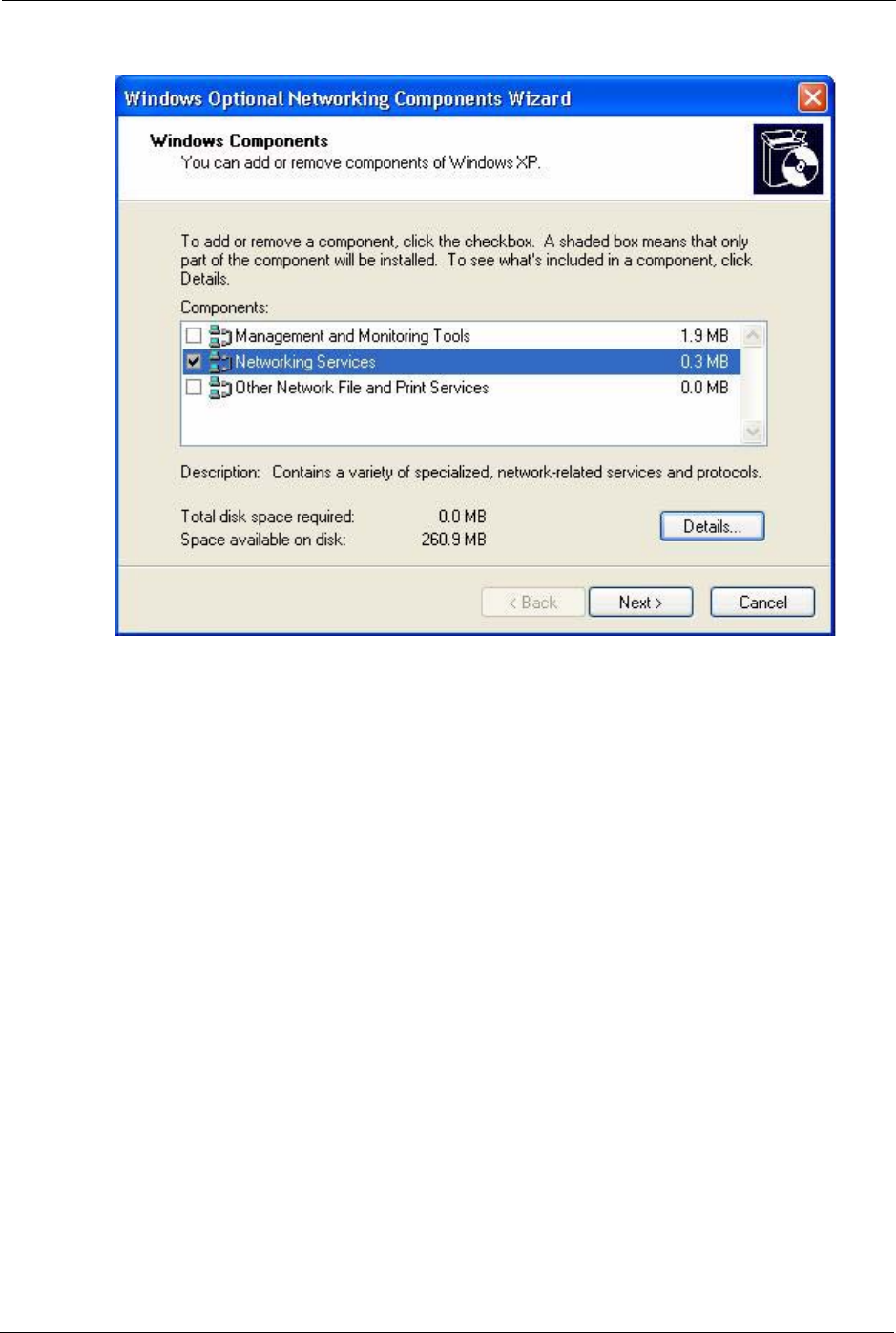
P-660H/HW/W-T Series User’ Guide
167 Chapter 14 Universal Plug-and-Play (UPnP)
Figure 73 Windows Optional Networking Components Wizard
5In the Networking Services window, select the Universal Plug and Play check box.
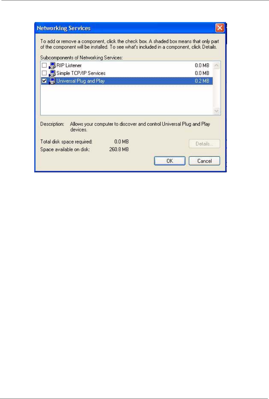
P-660H/HW/W-T Series User’ Guide
Chapter 14 Universal Plug-and-Play (UPnP) 168
Figure 74 Networking Services
6Click OK to go back to the Windows Optional Networking Component Wizard
window and click Next.
14.4 Using UPnP in Windows XP Example
This section shows you how to use the UPnP feature in Windows XP. You must already have
UPnP installed in Windows XP and UPnP activated on the Prestige.
Make sure the computer is connected to a LAN port of the Prestige. Turn on your computer
and the Prestige.
Auto-discover Your UPnP-enabled Network Device
1Click Start and Control Panel. Double-click Network Connections. An icon displays
under Internet Gateway.
2Right-click the icon and select Properties.
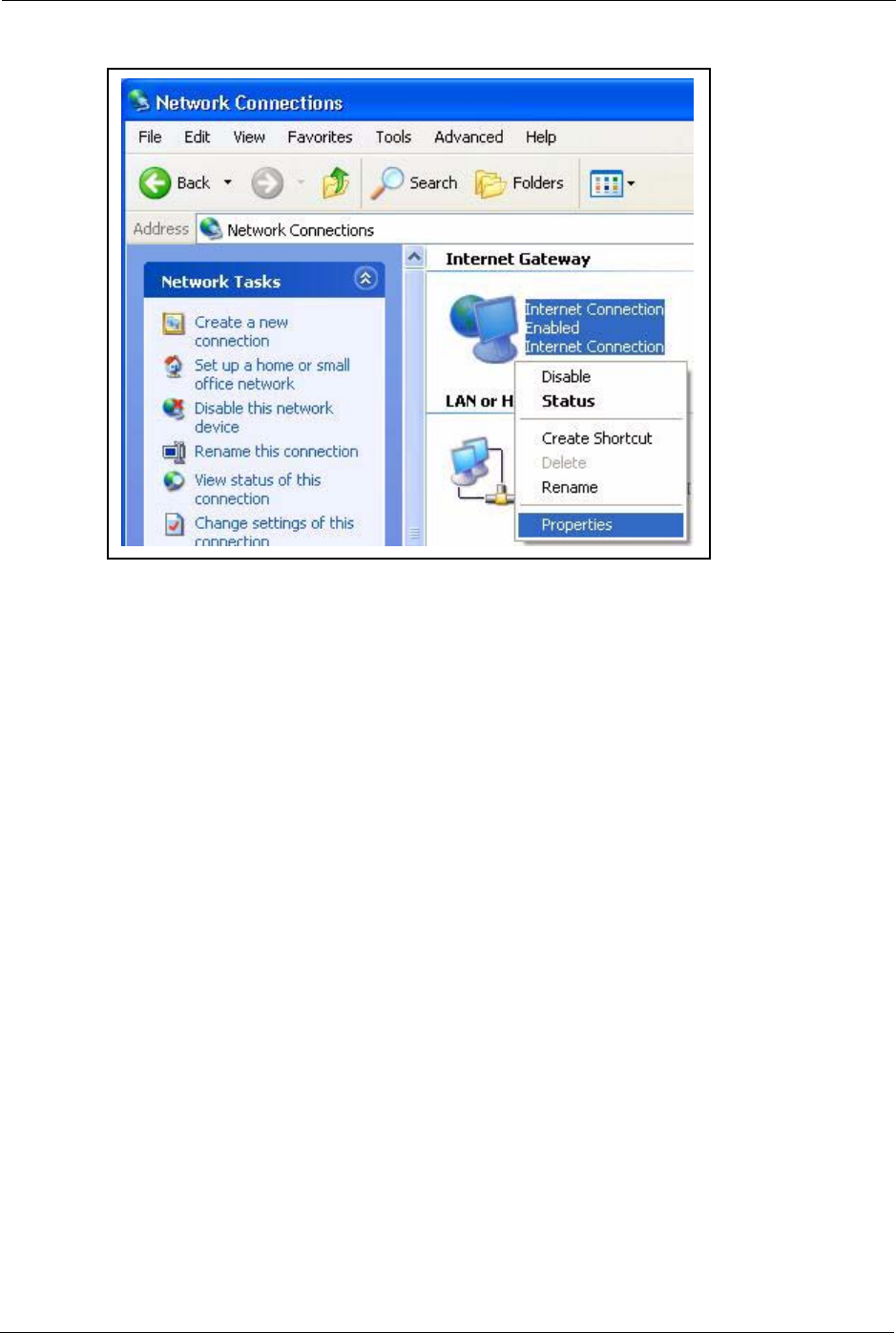
P-660H/HW/W-T Series User’ Guide
169 Chapter 14 Universal Plug-and-Play (UPnP)
Figure 75 Network Connections
3In the Internet Connection Properties window, click Settings to see the port mappings
there were automatically created.
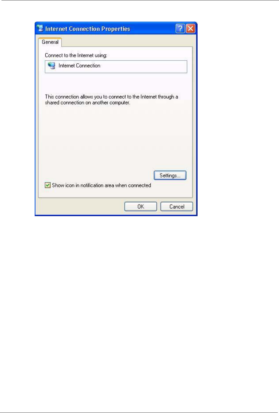
P-660H/HW/W-T Series User’ Guide
Chapter 14 Universal Plug-and-Play (UPnP) 170
Figure 76 Internet Connection Properties
4You may edit or delete the port mappings or click Add to manually add port mappings.