ZyXEL Communications P660HWTX 802.11g Wireless ADSL2+4 port Gateway User Manual 3
ZyXEL Communications Corporation 802.11g Wireless ADSL2+4 port Gateway Users Manual 3
Contents
- 1. Users Manual 1
- 2. Users Manual 2
- 3. Users Manual 3
- 4. Users Manual 4
Users Manual 3
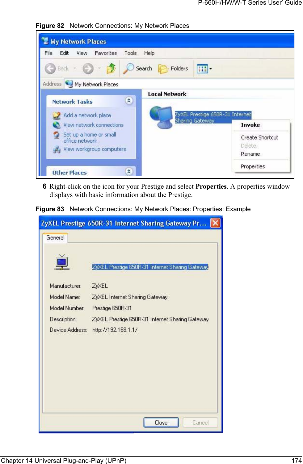
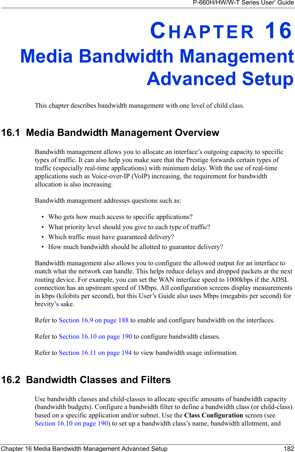
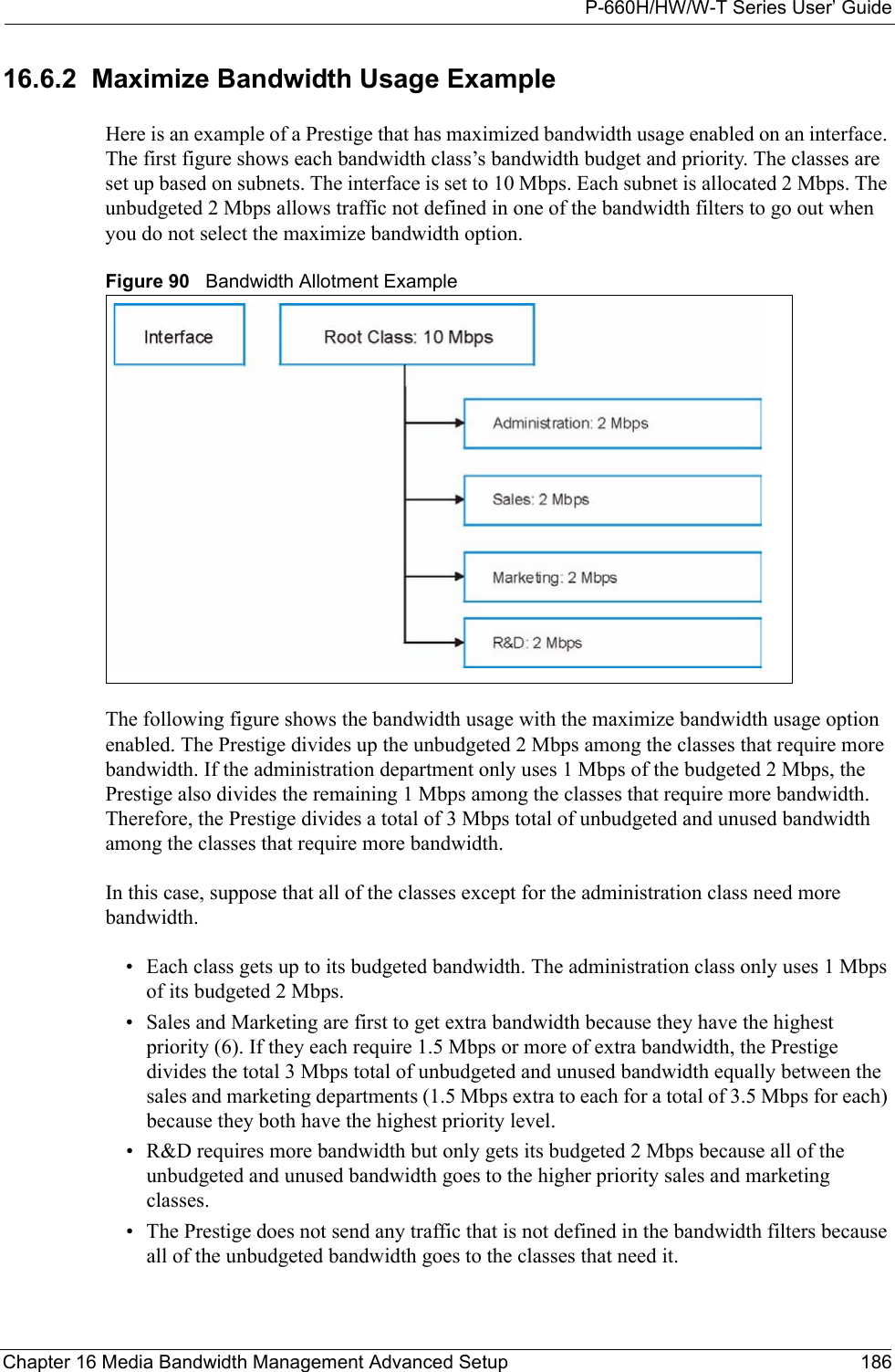
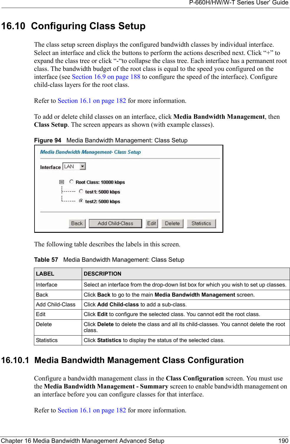
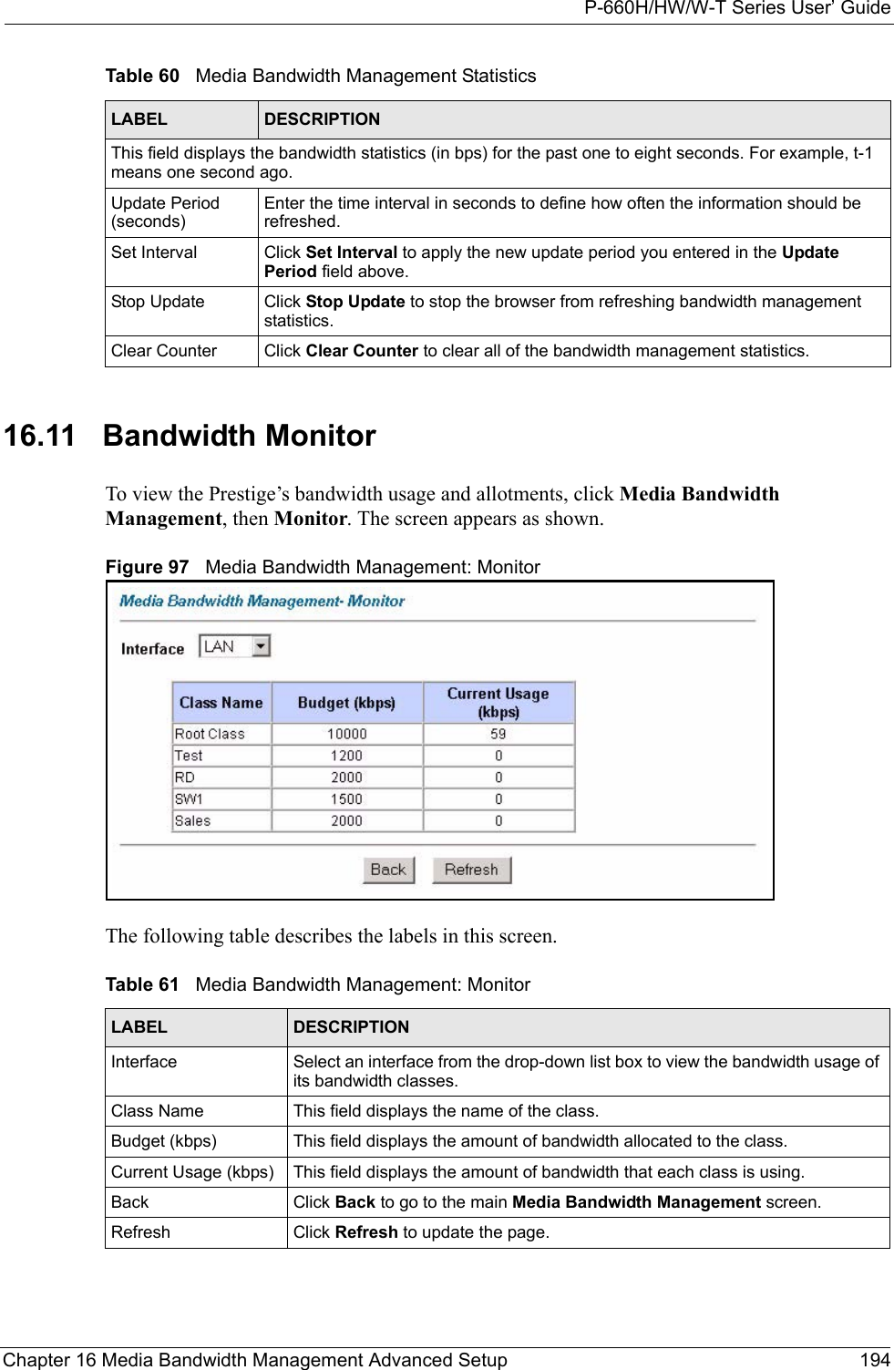
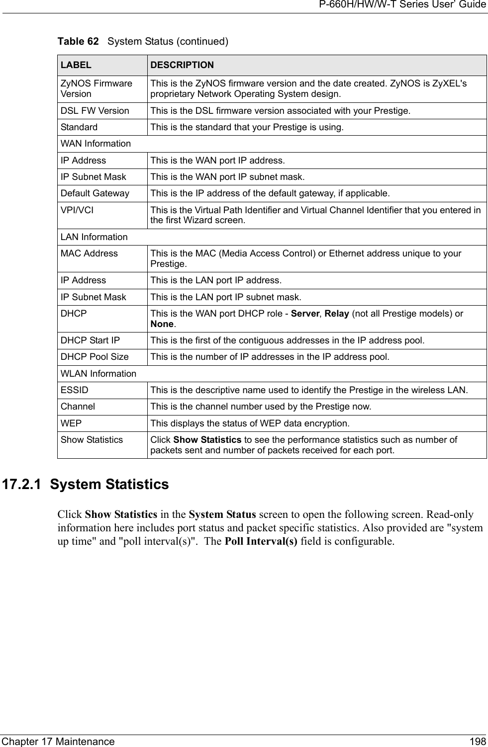
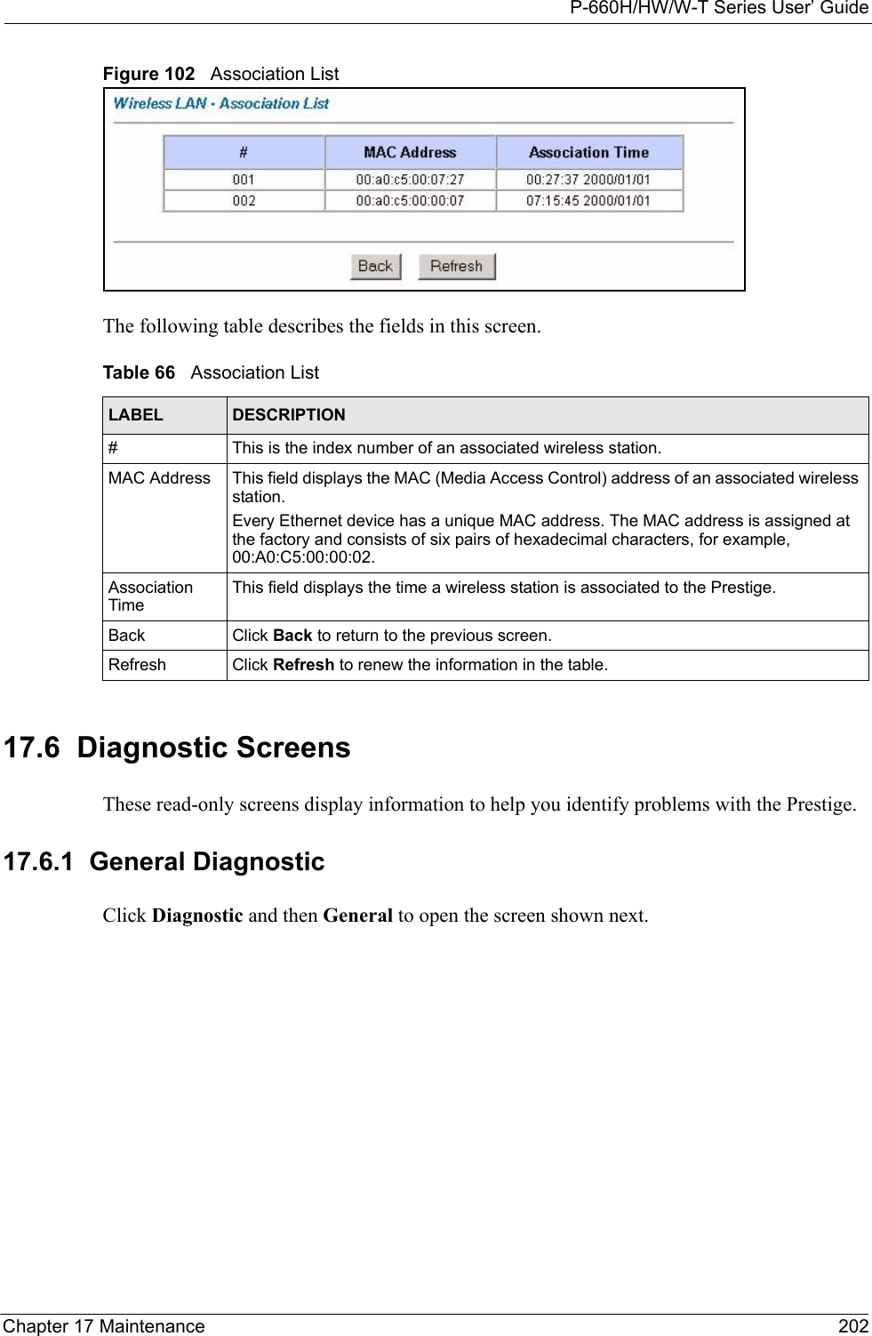

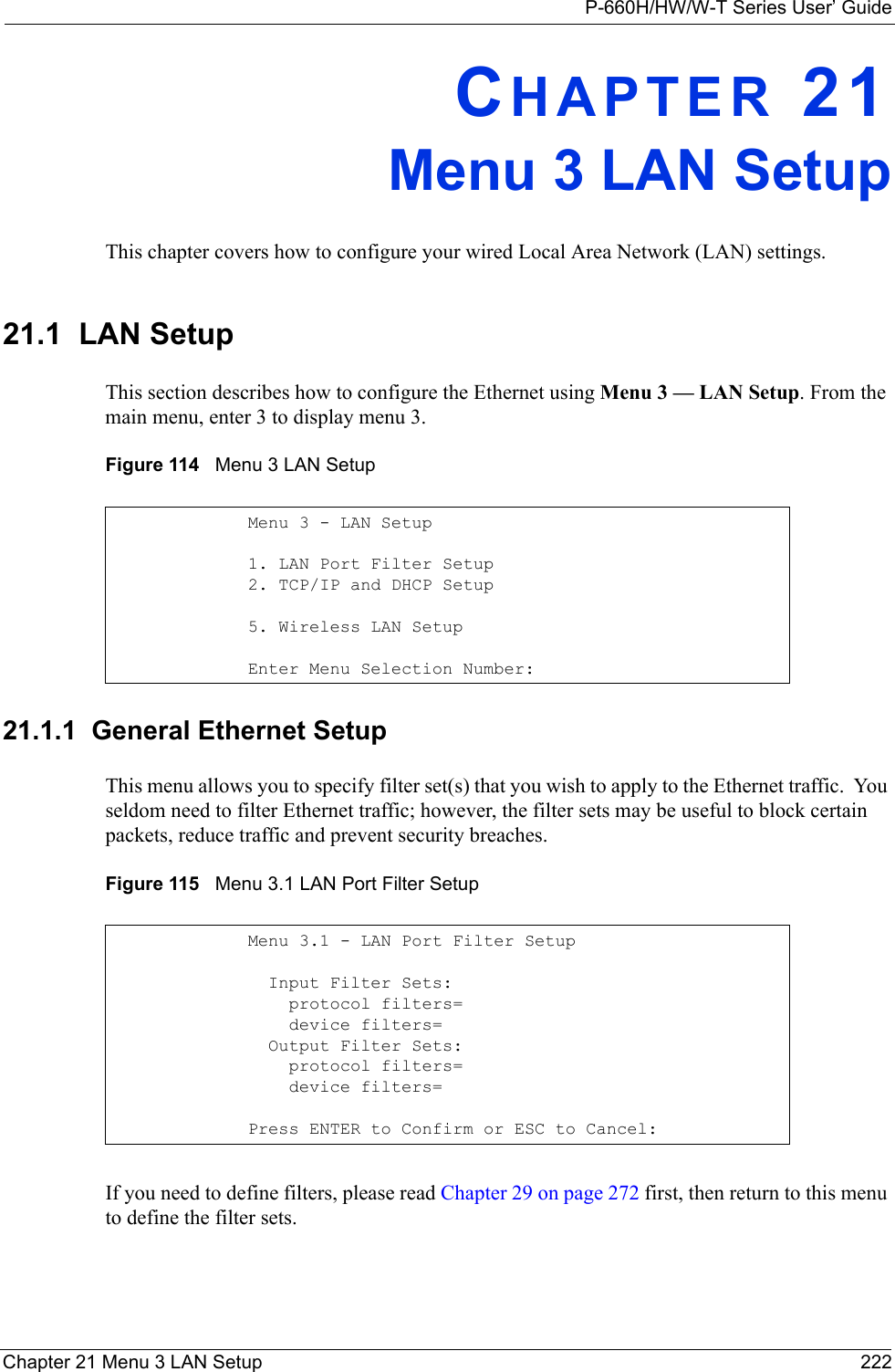
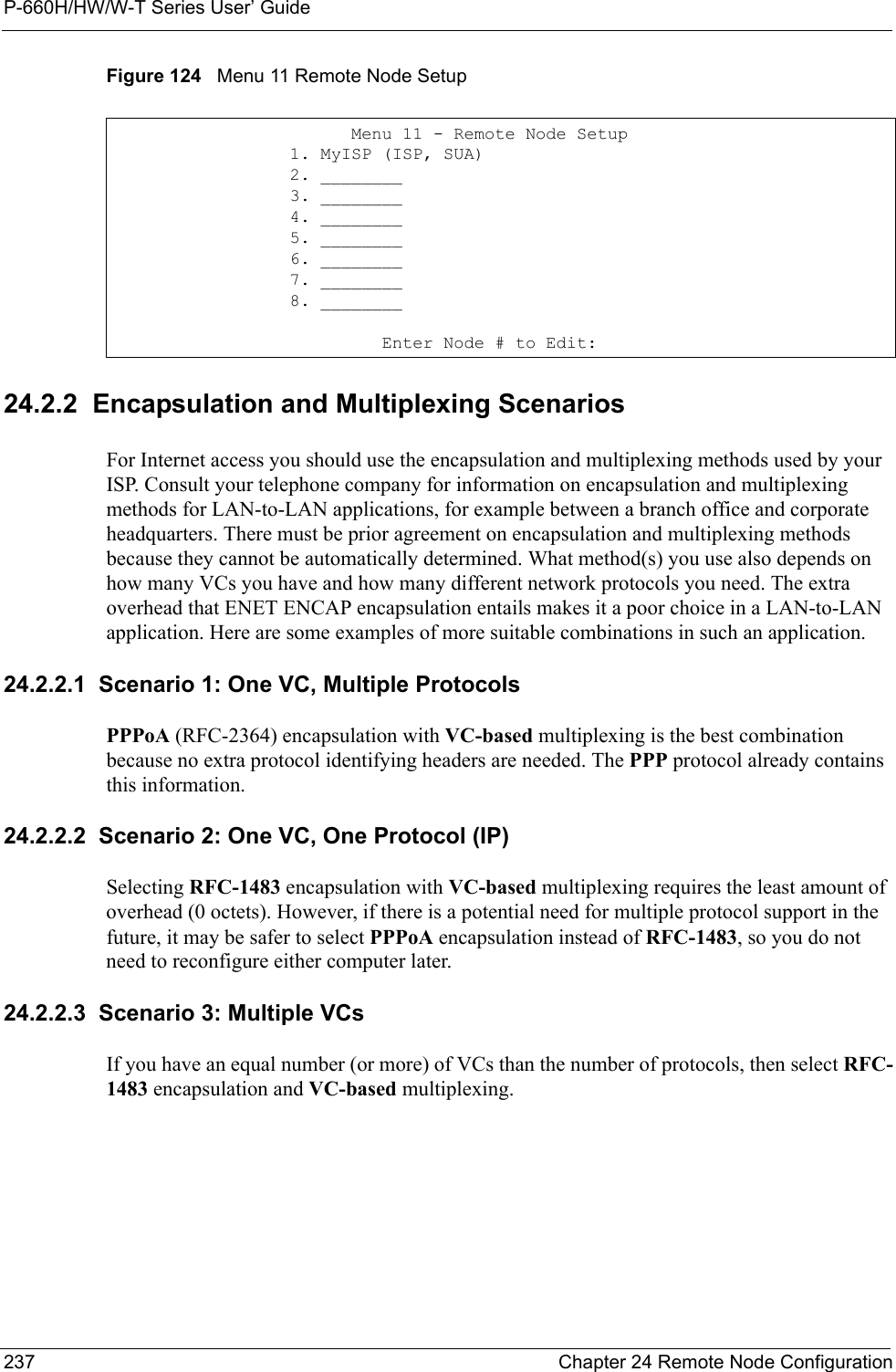
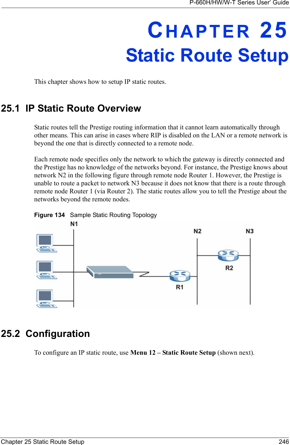
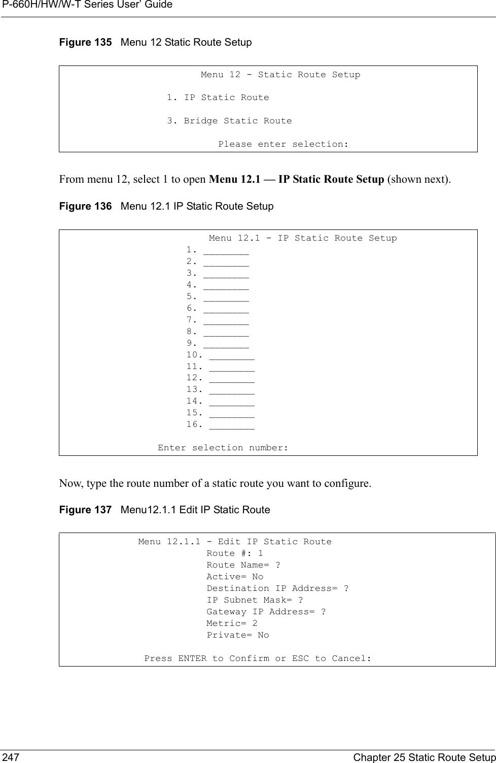
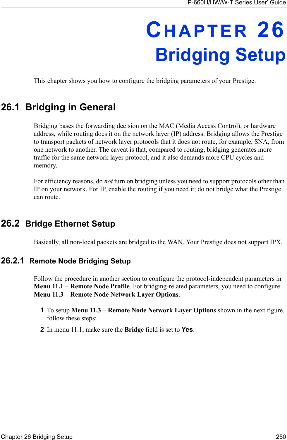
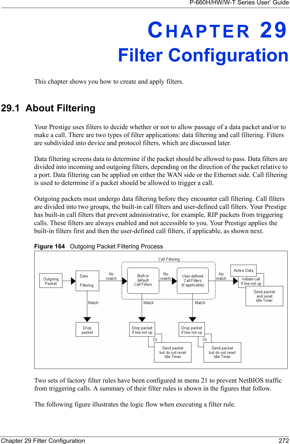
![P-660H/HW/W-T Series User’ GuideChapter 18 Introducing the SMT 208CHAPTER 18Introducing the SMTThis chapter explains how to access and navigate the System Management Terminal and gives an overview of its menus.18.1 SMT IntroductionThe Prestige’s SMT (System Management Terminal) is a menu-driven interface that you can access from a terminal emulator over a telnet connection. This chapter shows you how to access the SMT (System Management Terminal) menus via Telnet, how to navigate the SMT and how to configure SMT menus.18.1.1 Procedure for SMT Configuration via TelnetThe following procedure details how to telnet into your Prestige.1In Windows, click Start (usually in the bottom left corner), Run and then type "telnet 192.168.1.1" (the default IP address) and click OK. 2Enter “1234” in the Password field. 3After entering the password you will see the main menu.Please note that if there is no activity for longer than five minutes (default timeout period) after you log in, your Prestige will automatically log you out. You will then have to telnet into the Prestige again.18.1.2 Entering PasswordThe login screen appears after you press [ENTER], prompting you to enter the password, as shown next.For your first login, enter the default password "1234". As you type the password, the screen displays an asterisk "*" for each character you type.Please note that if there is no activity for longer than five minutes after you log in, your Prestige will automatically log you out.](https://usermanual.wiki/ZyXEL-Communications/P660HWTX.Users-Manual-3/User-Guide-566052-Page-38.png)
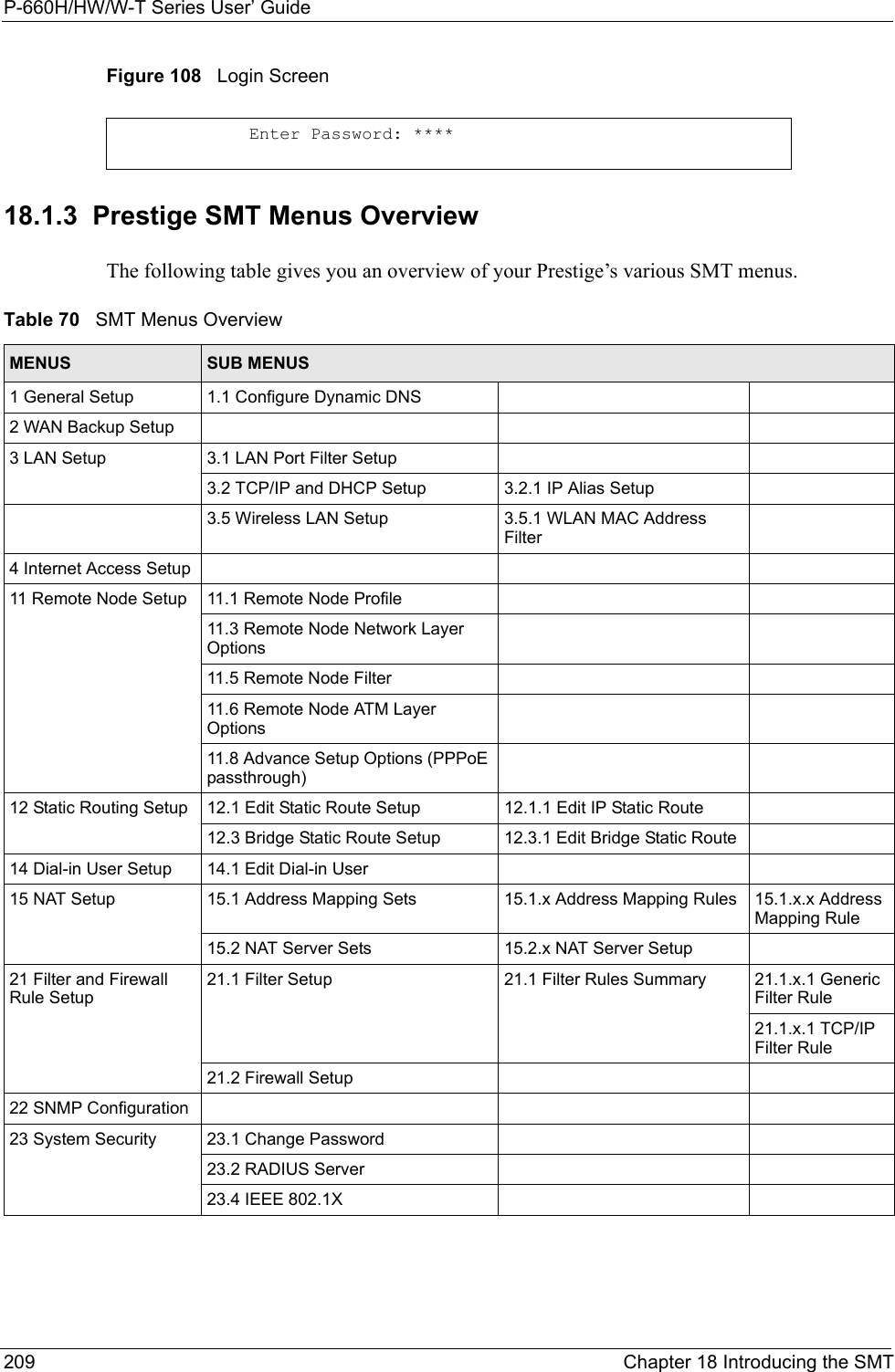
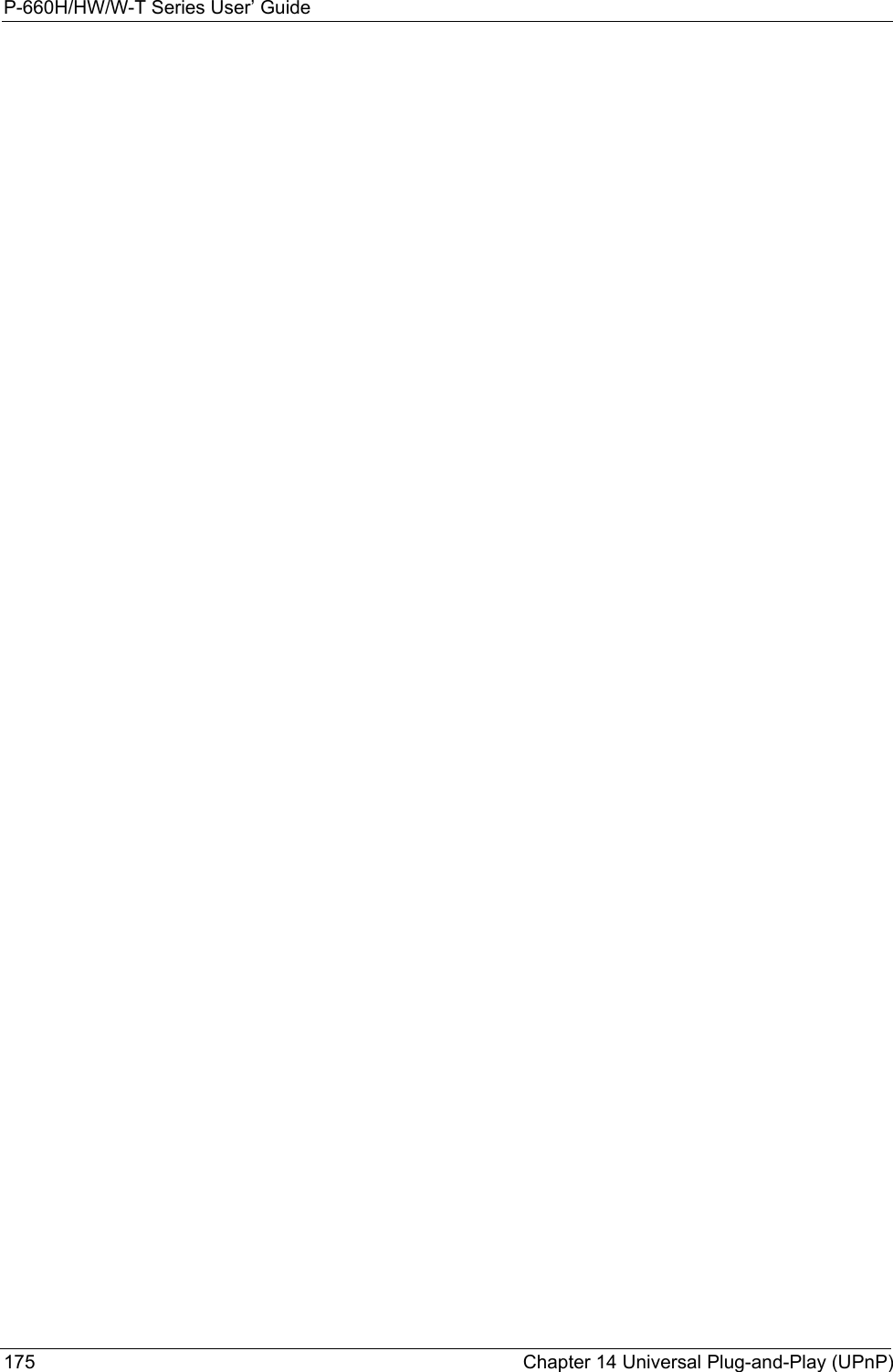
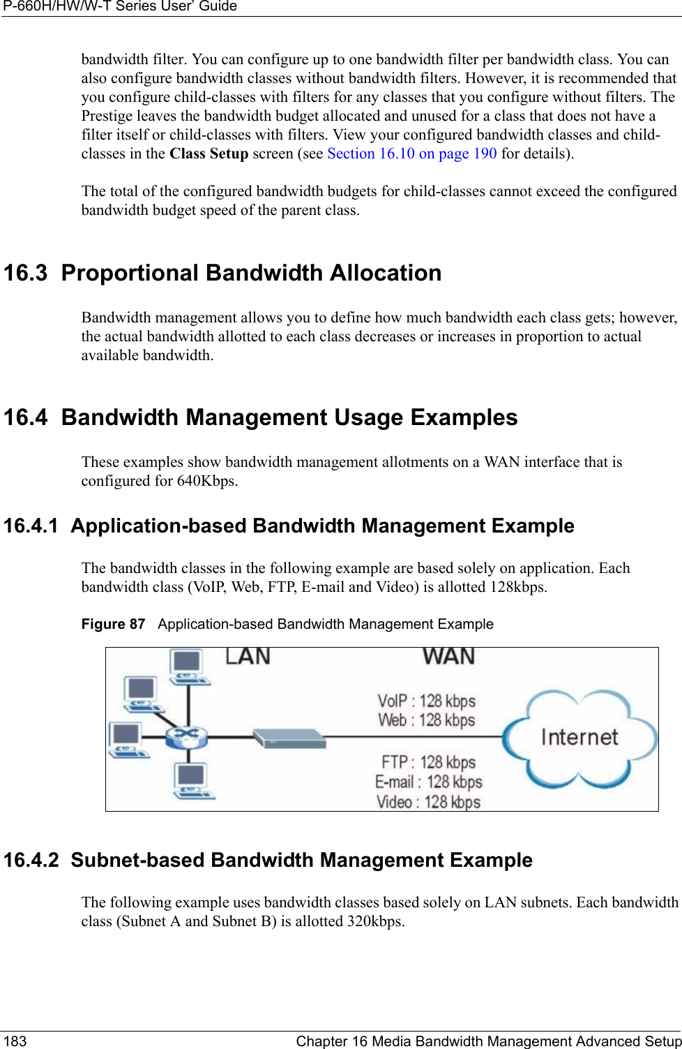
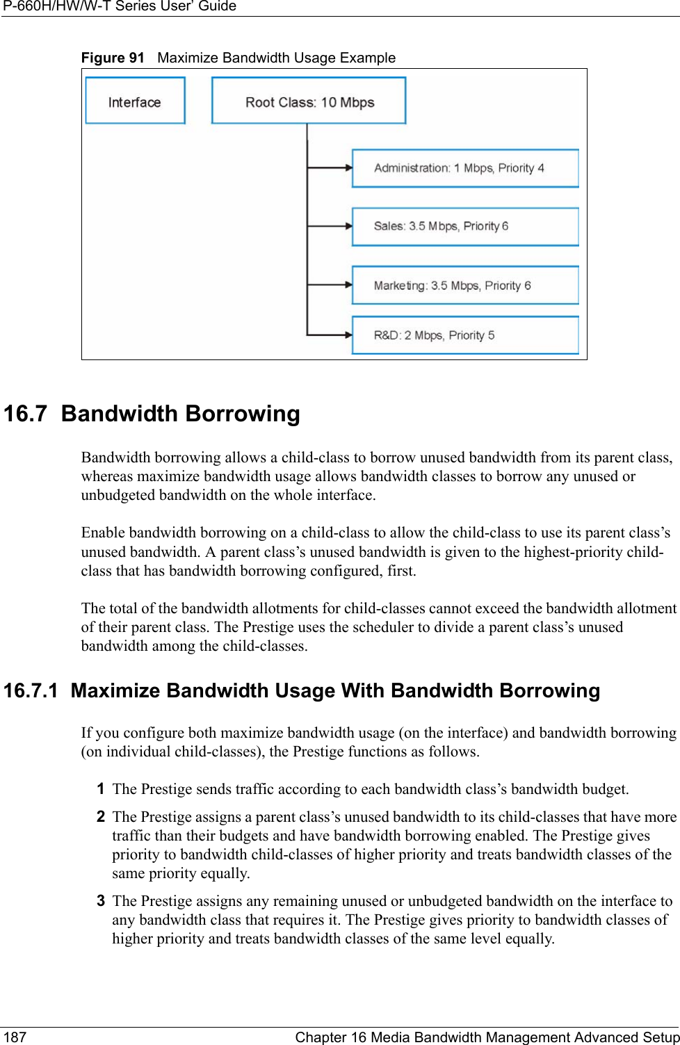
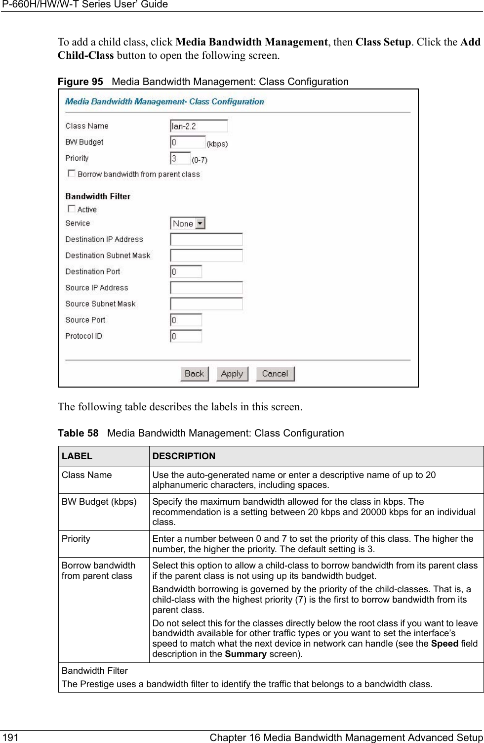
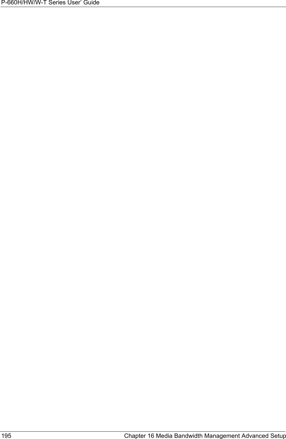
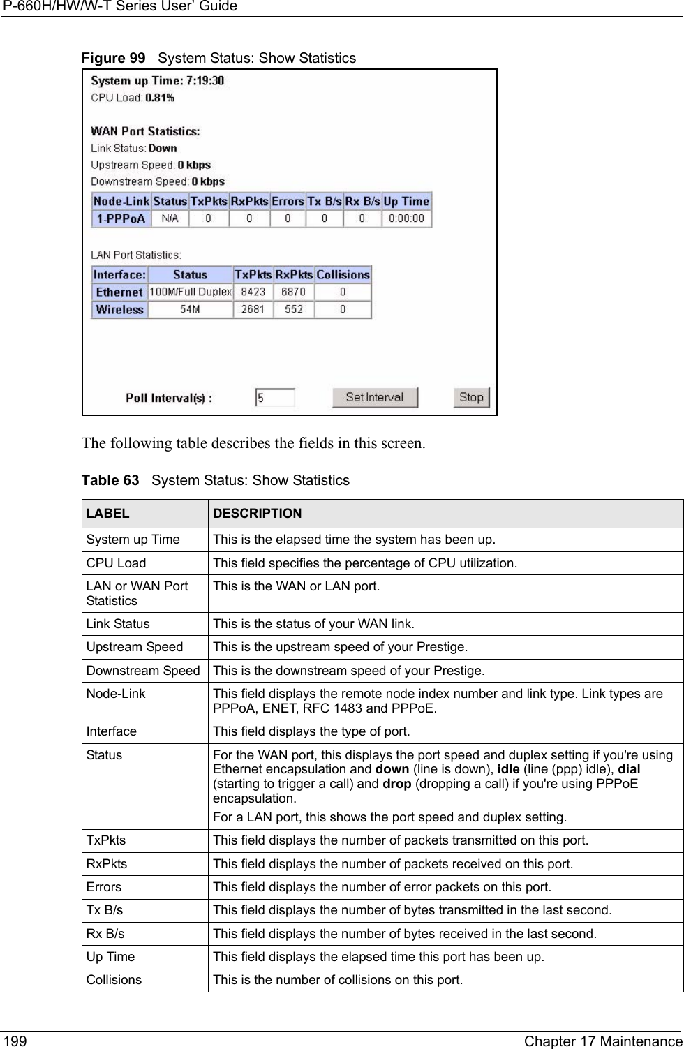
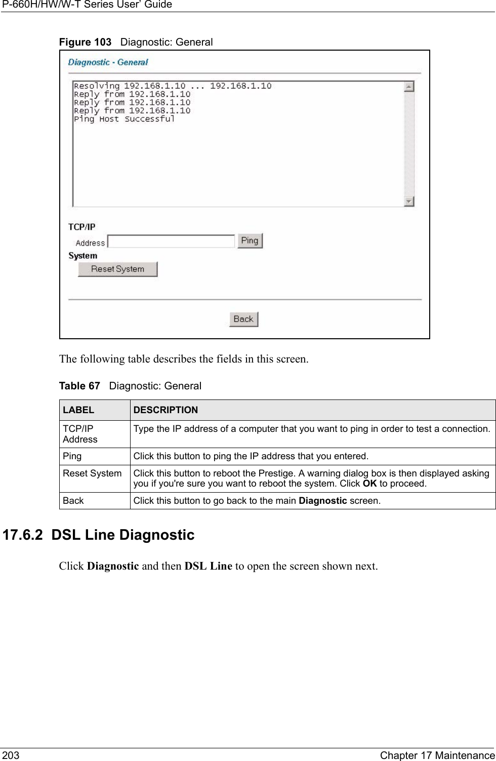
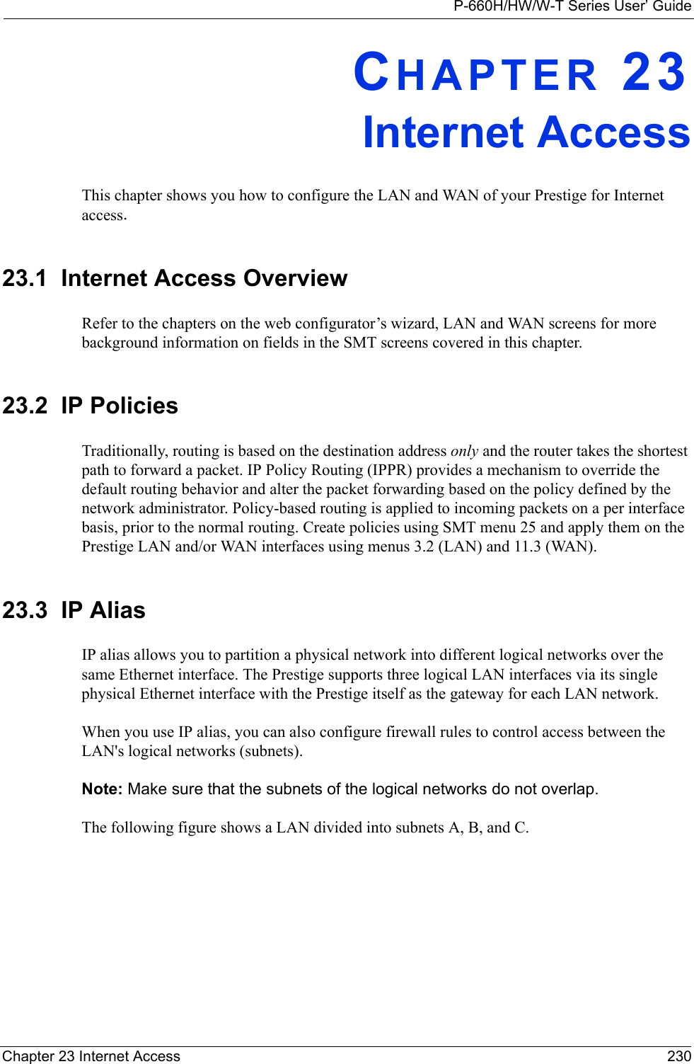
![P-660H/HW/W-T Series User’ GuideChapter 18 Introducing the SMT 21018.2 Navigating the SMT InterfaceThe SMT (System Management Terminal) is the interface that you use to configure your Prestige. Several operations that you should be familiar with before you attempt to modify the configuration are listed in the table below.24 System Maintenance 24.1 Status24.2 System Information and Console Port Speed24.2.1 Information24.2.2 Change Console Port Speed24.3 Log and Trace 24.3.1 View Error Log24.3.2 UNIX Syslog24.4 Diagnostic24.5 Backup Configuration24.6 Restore Configuration24.7 Upload Firmware 24.7.1 Upload System Firmware24.7.2 Upload System Configuration File24.8 Command Interpreter Mode24.9 Call Control 24.9.1 Budget Management24.10 Time and Date Setting24.11 Remote Management Control25 IP Routing Policy Setup25.1 IP Routing Policy Setup 25.1.1 IP Routing Policy26 Schedule Setup 26.1 Schedule Set SetupTable 70 SMT Menus Overview (continued)MENUS SUB MENUSTable 71 Navigating the SMT InterfaceOPERATION KEY STROKE DESCRIPTIONMove down to another menu[ENTER] To move forward to a submenu, type in the number of the desired submenu and press [ENTER].Move up to a previous menu[ESC] Press [ESC] to move back to the previous menu.Move to a hidden menuPress [SPACE BAR] to change No to Yes then press [ENTER].Fields beginning with "Edit" lead to hidden menus and have a default setting of No. Press [SPACE BAR] once to change No to Yes, then press [ENTER] to go to the "hidden" menu.Move the cursor [ENTER] or [UP]/[DOWN] arrow keys.Within a menu, press [ENTER] to move to the next field. You can also use the [UP]/[DOWN] arrow keys to move to the previous and the next field, respectively.](https://usermanual.wiki/ZyXEL-Communications/P660HWTX.Users-Manual-3/User-Guide-566052-Page-40.png)
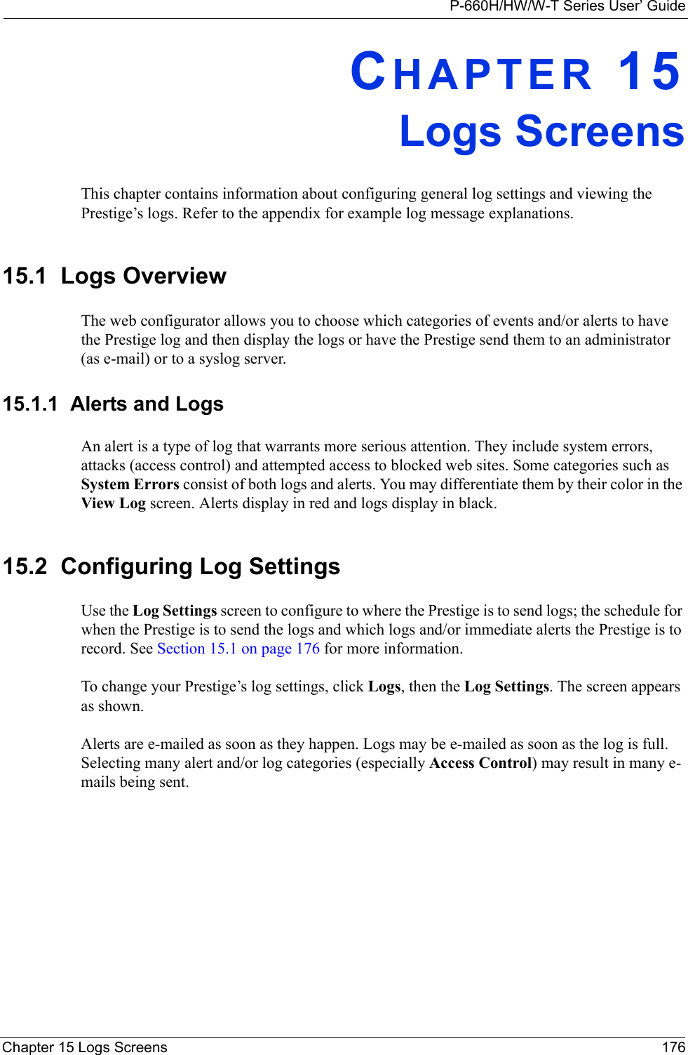
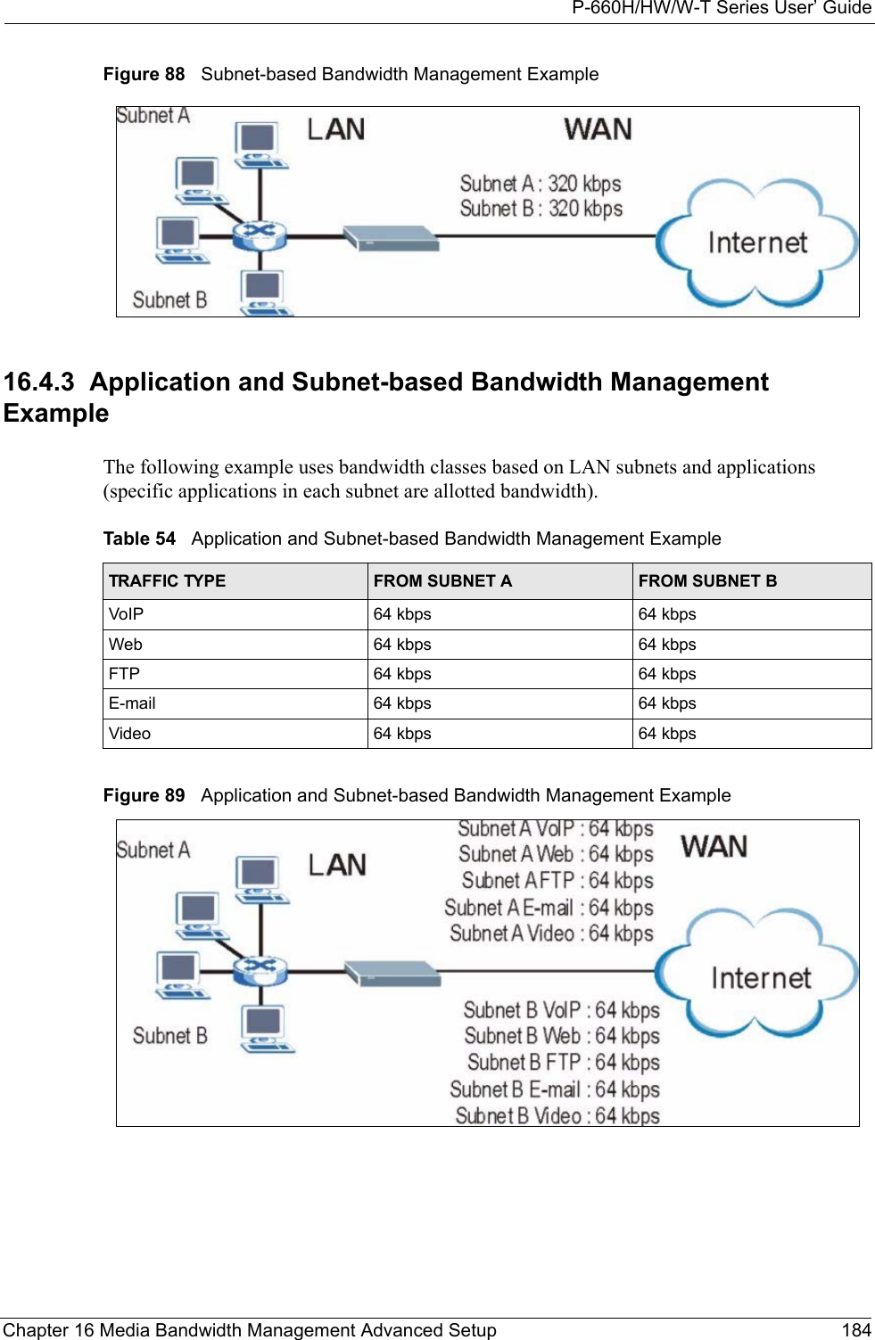
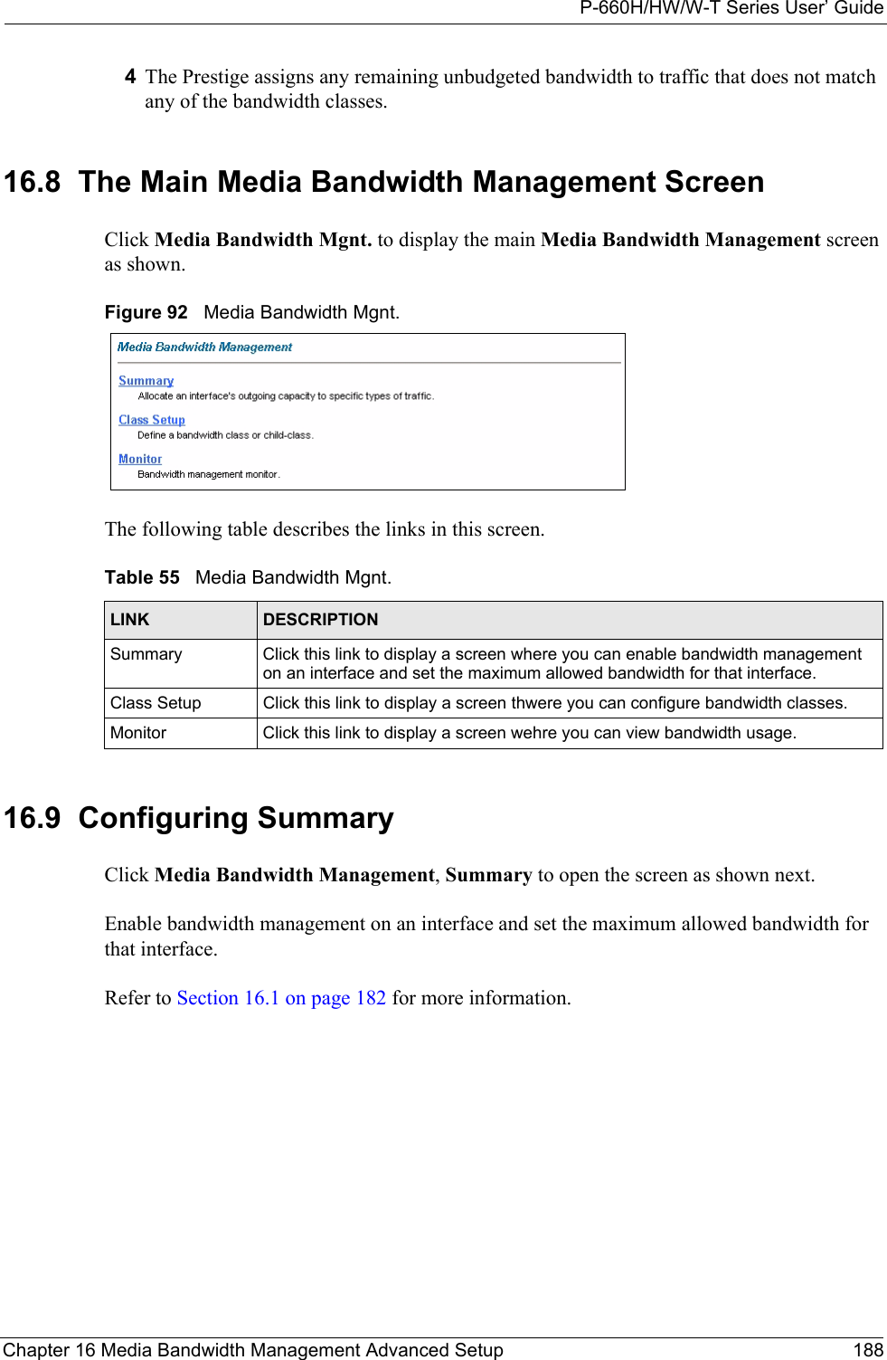
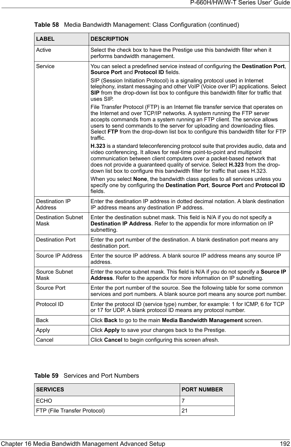
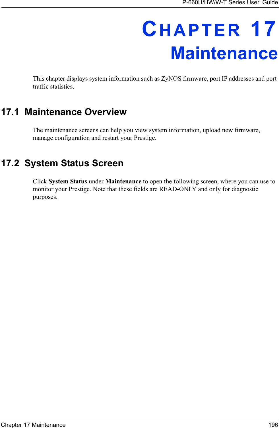
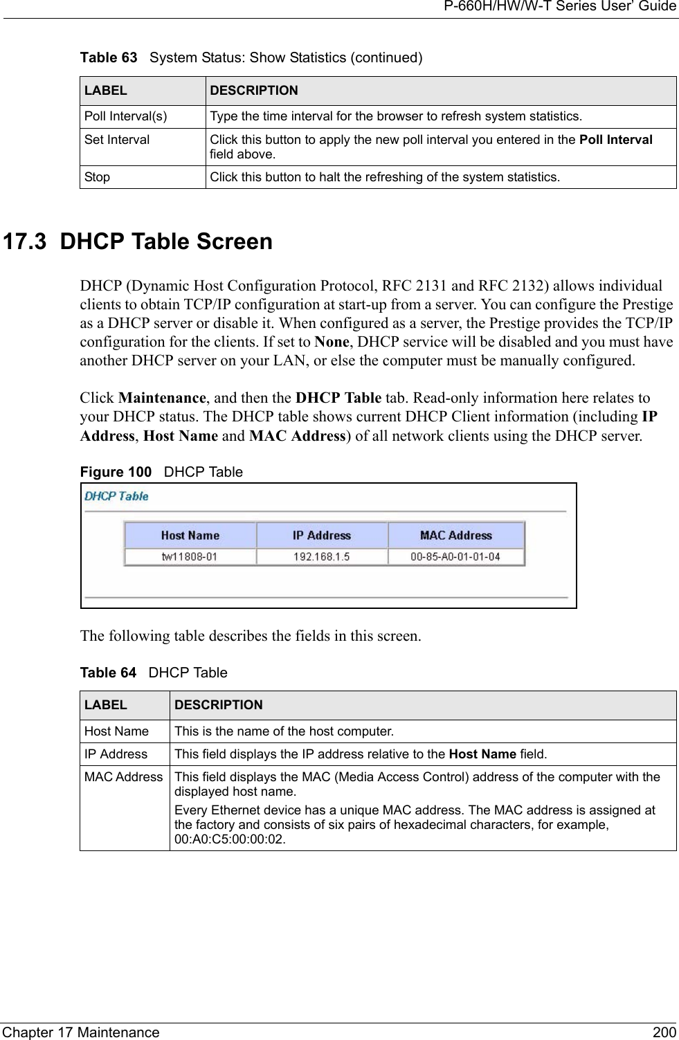
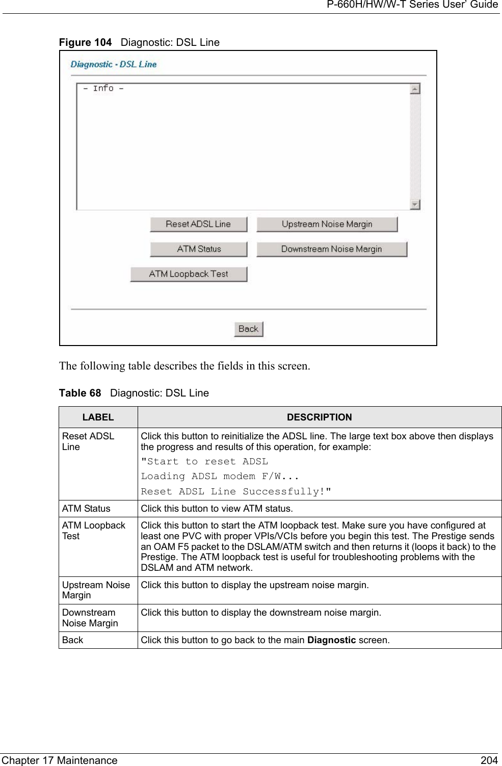
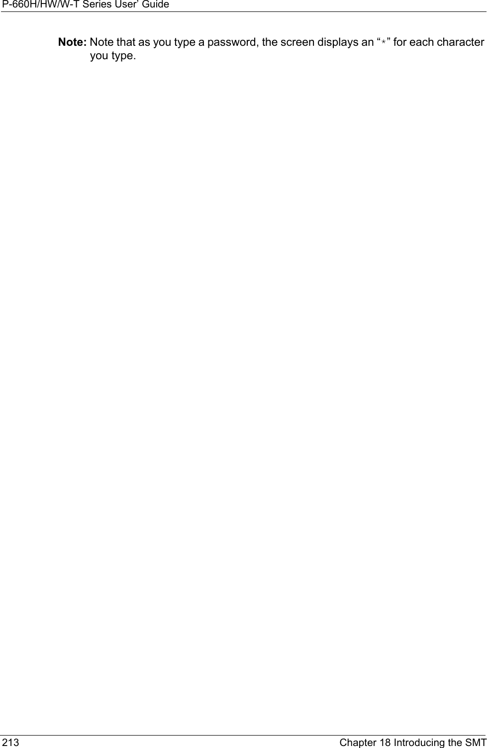
![P-660H/HW/W-T Series User’ Guide211 Chapter 18 Introducing the SMTAfter you enter the password, the SMT displays the main menu, as shown next.18.2.1 System Management Terminal Interface SummaryEntering informationType in or press [SPACE BAR], then press [ENTER].You need to fill in two types of fields. The first requires you to type in the appropriate information. The second allows you to cycle through the available choices by pressing [SPACE BAR].Required fields <? > or ChangeMeAll fields with the symbol <?> must be filled in order to be able to save the new configuration.All fields with ChangeMe must not be left blank in order to be able to save the new configuration.N/A fields <N/A> Some of the fields in the SMT will show a <N/A>. This symbol refers to an option that is Not Applicable.Save your configuration[ENTER] Save your configuration by pressing [ENTER] at the message "Press ENTER to confirm or ESC to cancel". Saving the data on the screen will take you, in most cases to the previous menu. Exit the SMT Type 99, then press [ENTER].Type 99 at the main menu prompt and press [ENTER] to exit the SMT interface.Table 72 SMT Main Menu Copyright (c) 1994 - 2004 ZyXEL Communications Corp. Prestige 660W-T1 Main Menu Getting Started Advanced Management 1. General Setup 21. Filter and Firewall Setup 2. WAN Backup Setup 22. SNMP Configuration 3. LAN Setup 23. System Security 4. Internet Access Setup 24. System Maintenance 25. IP Routing Policy Setup Advanced Applications 26. Schedule Setup 11. Remote Node Setup 12. Static Routing Setup 14. Dial-in User Setup 99. Exit 15. NAT Setup Enter Menu Selection Number:Table 71 Navigating the SMT InterfaceOPERATION KEY STROKE DESCRIPTIONTable 73 Main Menu Summary#MENU TITLE DESCRIPTION1 General Setup Use this menu to set up your general information.2 WAN Backup Setup Use this menu to setup traffic redirect and dial-back up.](https://usermanual.wiki/ZyXEL-Communications/P660HWTX.Users-Manual-3/User-Guide-566052-Page-41.png)
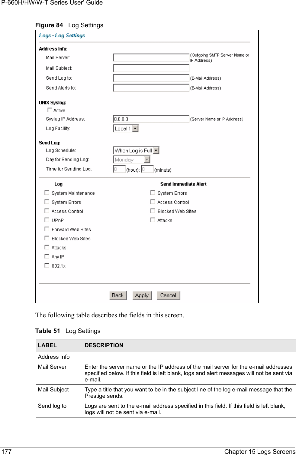
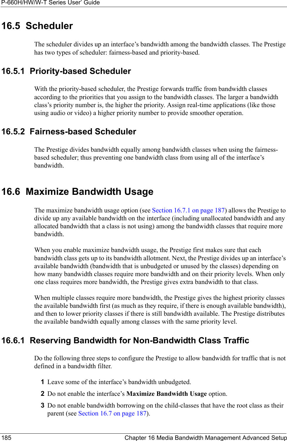
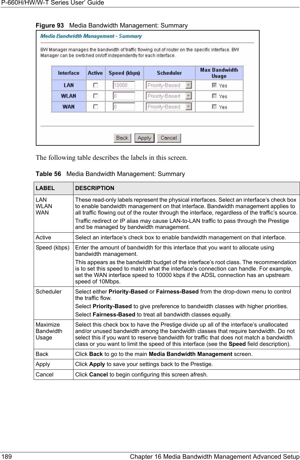
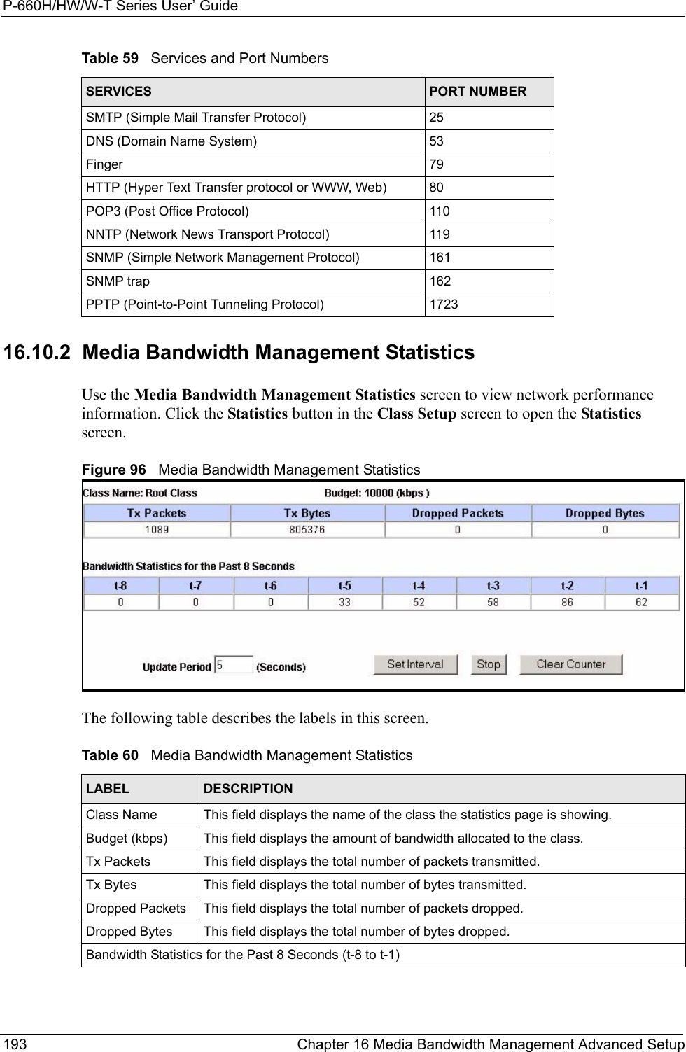
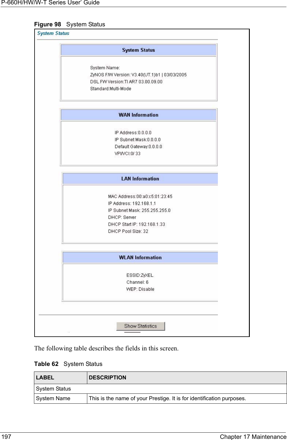
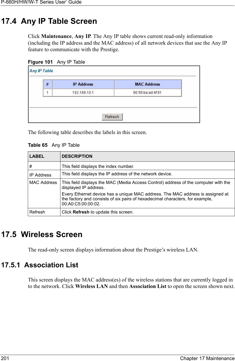
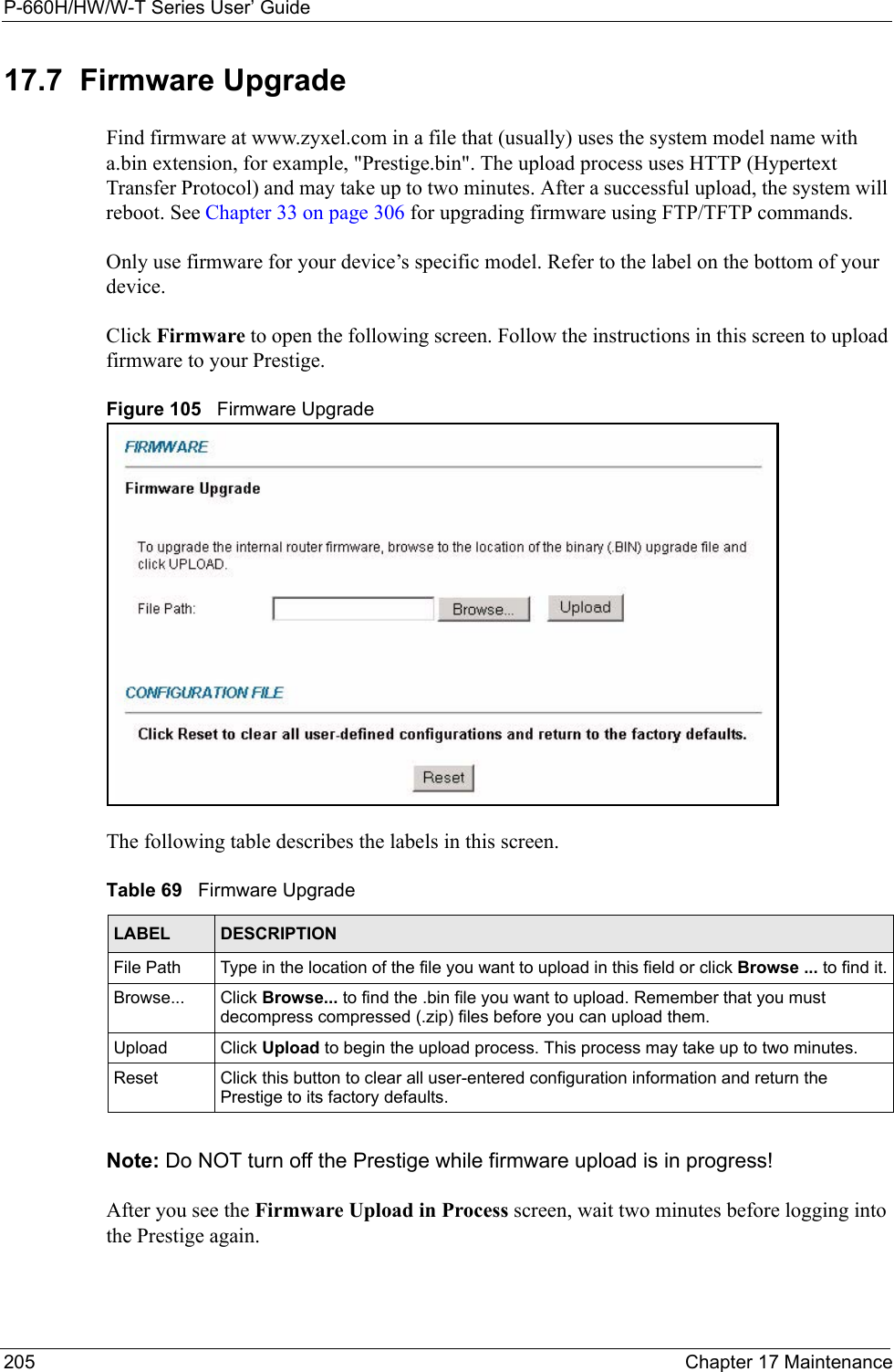
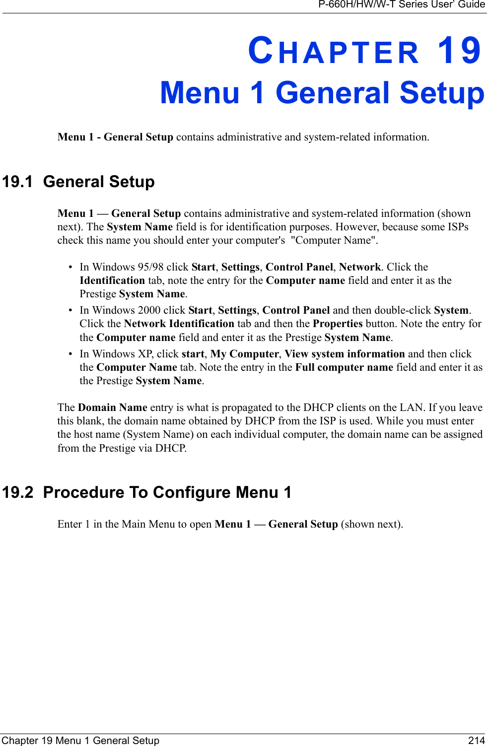
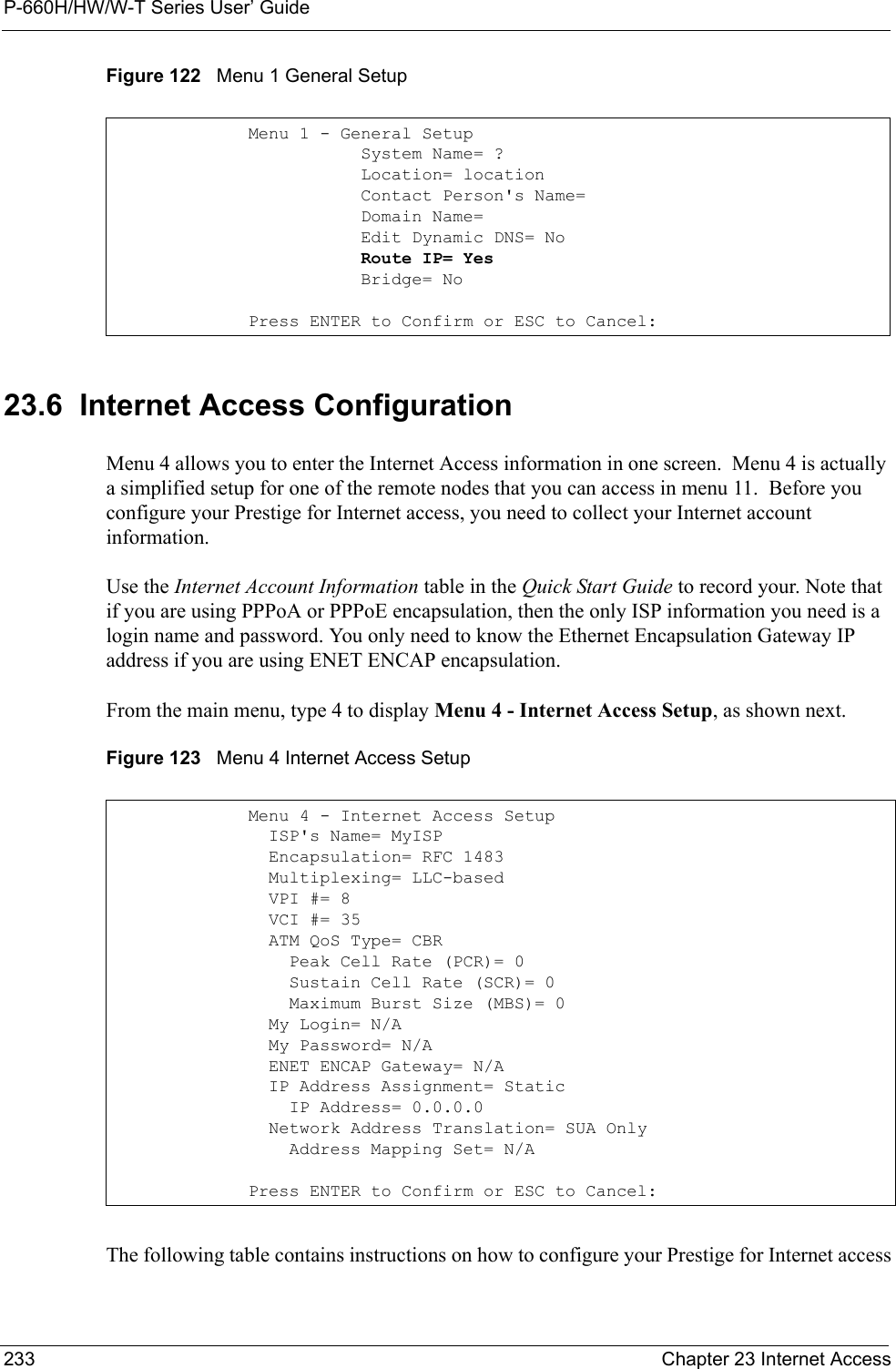
![P-660H/HW/W-T Series User’ GuideChapter 18 Introducing the SMT 21218.3 Changing the System PasswordChange the Prestige default password by following the steps shown next. 1Enter 23 in the main menu to display Menu 23 - System Security.2Enter 1 to display Menu 23.1 - System Security - Change Password as shown next.3Type your existing system password in the Old Password field, for example “1234", and press [ENTER].Figure 109 Menu 23.1 Change Password4Type your new system password in the New Password field (up to 30 characters), and press [ENTER].5Re-type your new system password in the Retype to confirm field for confirmation and press [ENTER].3 LAN Setup Use this menu to set up your wireless LAN and LAN connection.4 Internet Access Setup A quick and easy way to set up an Internet connection.11 Remote Node Setup Use this menu to set up the Remote Node for LAN-to-LAN connection, including Internet connection.12 Static Routing Setup Use this menu to set up static routes. 14 Dial-in User Setup Use this menu to set up local user profiles on the Prestige.15 NAT Setup Use this menu to specify inside servers when NAT is enabled.21 Filter and Firewall Setup Use this menu to configure filters, activate/deactivate the firewall and view the firewall log.22 SNMP Configuration Use this menu to set up SNMP related parameters.23 System Security Use this menu to set up wireless security and change your password.24 System Maintenance This menu provides system status, diagnostics, software upload, etc.25 IP Routing Policy Setup Use this menu to configure your IP routing policy.26 Schedule Setup Use this menu to schedule outgoing calls.99 Exit Use this to exit from SMT and return to a blank screen.Table 73 Main Menu Summary#MENU TITLE DESCRIPTIONMenu 23.1 - System Security - Change Password Old Password= ? New Password= ? Retype to confirm=?Enter here to CONFIRM or ESC to CANCEL:](https://usermanual.wiki/ZyXEL-Communications/P660HWTX.Users-Manual-3/User-Guide-566052-Page-42.png)
![P-660H/HW/W-T Series User’ Guide215 Chapter 19 Menu 1 General SetupFigure 110 Menu 1 General SetupFill in the required fields. Refer to the table shown next for more information about these fields.19.2.1 Procedure to Configure Dynamic DNSNote: If you have a private WAN IP address, then you cannot use dynamic DNS.To configure dynamic DNS, go to Menu 1 — General Setup and select Yes in the Edit Dynamic DNS field. Press [ENTER] to display Menu 1.1— Configure Dynamic DNS as shown next. Menu 1 General Setup System Name= ? Location= Contact Person's Name= Domain Name= Edit Dynamic DNS= No Route IP= Yes Bridge= NoPress ENTER to Confirm or ESC to Cancel:Table 74 Menu 1 General SetupFIELD DESCRIPTIONSystem Name Choose a descriptive name for identification purposes. This name can be up to 30 alphanumeric characters long. Spaces are not allowed, but dashes “-” and underscores "_" are accepted. Location (optional) Enter the geographic location (up to 31 characters) of your Prestige.Contact Person's Name (optional)Enter the name (up to 30 characters) of the person in charge of this Prestige.Domain Name Enter the domain name (if you know it) here. If you leave this field blank, the ISP may assign a domain name via DHCP. You can go to menu 24.8 and type "sys domainname" to see the current domain name used by your gateway.If you want to clear this field just press the [SPACE BAR]. The domain name entered by you is given priority over the ISP assigned domain name. Edit Dynamic DNS Press the [SPACE BAR] to select Yes or No (default). Select Yes to configure Menu 1.1 — Configure Dynamic DNS (discussed next).Route IP Set this field to Yes to enable or No to disable IP routing. You must enable IP routing for Internet access. Bridge Turn on/off bridging for protocols not supported (for example, SNA) or not turned on in the previous Route IP field. Select Yes to turn bridging on; select No to turn bridging off. When you have completed this menu, press [ENTER] at the prompt “Press ENTER to Confirm or ESC to Cancel:” to save your configuration, or press [ESC] at any time to cancel.](https://usermanual.wiki/ZyXEL-Communications/P660HWTX.Users-Manual-3/User-Guide-566052-Page-45.png)
![P-660H/HW/W-T Series User’ GuideChapter 19 Menu 1 General Setup 216Figure 111 Menu 1.1 Configure Dynamic DNS Follow the instructions in the next table to configure dynamic DNS parameters. Menu 1.1 - Configure Dynamic DNS Service Provider= WWW.DynDNS.ORG Active= No Host= EMAIL= USER= Password= ******** Enable Wildcard= No Press ENTER to Confirm or ESC to Cancel:Table 75 Menu 1.1 Configure Dynamic DNSFIELD DESCRIPTIONService Provider This is the name of your dynamic DNS service provider. Active Press [SPACE BAR] to select Yes and then press [ENTER] to make dynamic DNS active.Host Enter the domain name assigned to your Prestige by your dynamic DNS provider. EMAIL Enter your e-mail address.User Enter your user name.Password Enter the password assigned to you. Enable Wildcard Your Prestige supports DYNDNS Wildcard. Press [SPACE BAR] and then [ENTER] to select Yes or No This field is N/A when you choose DDNS client as your service provider.When you have completed this menu, press [ENTER] at the prompt “Press ENTER to Confirm or ESC to Cancel:” to save your configuration, or press [ESC] at any time to cancel.](https://usermanual.wiki/ZyXEL-Communications/P660HWTX.Users-Manual-3/User-Guide-566052-Page-46.png)

![P-660H/HW/W-T Series User’ GuideChapter 20 Menu 2 WAN Backup Setup 218CHAPTER 20Menu 2 WAN Backup SetupThis chapter describes how to configure traffic redirect and dial-backup using menu 2 and 2.1.20.1 Introduction to WAN Backup SetupThis chapter explains how to configure the Prestige for traffic redirect and dial backup connections.20.2 Configuring Dial Backup in Menu 2From the main menu, enter 2 to open menu 2.Figure 112 Menu 2 WAN Backup SetupThe following table describes the fields in this menu. Menu 2 - Wan Backup Setup Check Mechanism = DSL Link Check WAN IP Address1 = 0.0.0.0 Check WAN IP Address2 = 0.0.0.0 Check WAN IP Address3 = 0.0.0.0 KeepAlive Fail Tolerance = 0 Recovery Interval(sec) = 0 ICMP Timeout(sec) = 0 Traffic Redirect = No Press ENTER to Confirm or ESC to Cancel:Table 76 Menu 2 WAN Backup SetupFIELD DESCRIPTIONCheck Mechanism Press [SPACE BAR] and then press [ENTER] to select the method that the Prestige uses to check the DSL connection.Select DSL Link to have the Prestige check the DSL connection’s physical layer. Select ICMP to have the Prestige periodically ping the IP addresses configured in the Check WAN IP Address fields.Check WAN IP Address1-3Configure this field to test your Prestige's WAN accessibility. Type the IP address of a reliable nearby computer (for example, your ISP's DNS server address). When using a WAN backup connection, the Prestige periodically pings the addresses configured here and uses the other WAN backup connection (if configured) if there is no response.](https://usermanual.wiki/ZyXEL-Communications/P660HWTX.Users-Manual-3/User-Guide-566052-Page-48.png)
![P-660H/HW/W-T Series User’ Guide219 Chapter 20 Menu 2 WAN Backup Setup20.2.1 Traffic Redirect SetupConfigure parameters that determine when the Prestige will forward WAN traffic to the backup gateway using Menu 2.1 — Traffic Redirect Setup. Figure 113 Menu 2.1Traffic Redirect SetupThe following table describes the fields in this menu.KeepAlive Fail ToleranceType the number of times (2 recommended) that your Prestige may ping the IP addresses configured in the Check WAN IP Address field without getting a response before switching to a WAN backup connection (or a different WAN backup connection).Recovery Interval(sec) When the Prestige is using a lower priority connection (usually a WAN backup connection), it periodically checks to whether or not it can use a higher priority connection.Type the number of seconds (30 recommended) for the Prestige to wait between checks. Allow more time if your destination IP address handles lots of traffic.ICMP Timeout Type the number of seconds for an ICMP session to wait for the ICMP responseTraffic Redirect Press [SPACE BAR] to select Yes or No. Select Yes and press [ENTER] to configure Menu 2.1 Traffic Redirect Setup.Select No (default) if you do not want to configure this feature. When you have completed this menu, press [ENTER] at the prompt “Press ENTER to Confirm or ESC to Cancel:” to save your configuration, or press [ESC] at any time to cancel.Table 76 Menu 2 WAN Backup Setup (continued)FIELD DESCRIPTION Menu 2.1 - Traffic Redirect Setup Active= No Configuration: Backup Gateway IP Address= 0.0.0.0 Metric= 15 Press ENTER to Confirm or ESC to Cancel:Table 77 Menu 2.1Traffic Redirect SetupFIELD DESCRIPTIONActive. Press [SPACE BAR] and select Yes (to enable) or No (to disable) traffic redirect setup. The default is NoConfigurationBackup Gateway IP AddressEnter the IP address of your backup gateway in dotted decimal notation.The Prestige automatically forwards traffic to this IP address if the Prestige’s Internet connection terminates.](https://usermanual.wiki/ZyXEL-Communications/P660HWTX.Users-Manual-3/User-Guide-566052-Page-49.png)
![P-660H/HW/W-T Series User’ GuideChapter 20 Menu 2 WAN Backup Setup 220Metric This field sets this route's priority among the routes the Prestige uses. The metric represents the "cost of transmission". A router determines the best route for transmission by choosing a path with the lowest "cost". RIP routing uses hop count as the measurement of cost, with a minimum of "1" for directly connected networks. The number must be between "1" and "15"; a number greater than "15" means the link is down. The smaller the number, the lower the "cost"When you have completed this menu, press [ENTER] at the prompt “Press ENTER to Confirm or ESC to Cancel:” to save your configuration, or press [ESC] at any time to cancel.Table 77 Menu 2.1Traffic Redirect SetupFIELD DESCRIPTION](https://usermanual.wiki/ZyXEL-Communications/P660HWTX.Users-Manual-3/User-Guide-566052-Page-50.png)

![P-660H/HW/W-T Series User’ Guide223 Chapter 21 Menu 3 LAN Setup21.2 Protocol Dependent Ethernet SetupDepending on the protocols for your applications, you need to configure the respective Ethernet Setup, as outlined below.• TCP/IP Ethernet setup• Bridging Ethernet setup21.3 TCP/IP Ethernet Setup and DHCPUse menu 3.2 to configure your Prestige for TCP/IP.To edit menu 3.2, enter 3 from the main menu to display Menu 3 — LAN Setup. When menu 3 appears, press 2 and press [ENTER] to display Menu 3.2 — TCP/IP and DHCP Ethernet Setup, as shown next:Figure 116 Menu 3.2 TCP/IP and DHCP Ethernet Setup Menu 3.2 - TCP/IP and DHCP Setup DHCP Setup DHCP= Server Client IP Pool Starting Address= 192.168.1.33 Size of Client IP Pool= 32 Primary DNS Server= 0.0.0.0 Secondary DNS Server= 0.0.0.0 Remote DHCP Server= N/A TCP/IP Setup: IP Address= 192.168.1.1 IP Subnet Mask= 255.255.255.0 RIP Direction= None Version= N/A Multicast= None IP Policies= Edit IP Alias= No Press ENTER to Confirm or ESC to Cancel:](https://usermanual.wiki/ZyXEL-Communications/P660HWTX.Users-Manual-3/User-Guide-566052-Page-53.png)
![P-660H/HW/W-T Series User’ GuideChapter 21 Menu 3 LAN Setup 224Follow the instructions in the following table on how to configure the DHCP fields. Follow the instructions in the following table to configure TCP/IP parameters for the Ethernet port.Table 78 DHCP Ethernet SetupFIELD DESCRIPTION DHCP Setup DHCP If set to Server, your Prestige can assign IP addresses, an IP default gateway and DNS servers to Windows 95, Windows NT and other systems that support the DHCP client. If set to None, the DHCP server will be disabled. If set to Relay, the Prestige acts as a surrogate DHCP server and relays DHCP requests and responses between the remote server and the clients. Enter the IP address of the actual, remote DHCP server in the Remote DHCP Server in this case.When DHCP server is used, the following items need to be set:Client IP Pool Starting AddressThis field specifies the first of the contiguous addresses in the IP address pool.Size of Client IP Pool This field specifies the size or count of the IP address pool.Primary DNS ServerSecondary DNS ServerEnter the IP addresses of the DNS servers. The DNS servers are passed to the DHCP clients along with the IP address and the subnet mask. Remote DHCP Serve If Relay is selected in the DHCP field above then enter the IP address of the actual remote DHCP server here.Table 79 TCP/IP Ethernet SetupFIELD DESCRIPTIONTCP/IP Setup IP Address Enter the (LAN) IP address of your Prestige in dotted decimal notationIP Subnet Mask Your Prestige will automatically calculate the subnet mask based on the IP address that you assign. Unless you are implementing subnetting, use the subnet mask computed by the Prestige (refer to the appendices for more information).RIP Direction Press [SPACE BAR] to select the RIP direction. Choices are Both, In Only, Out Only or None. Version Press [SPACE BAR] to select the RIP version. Choices are RIP-1, RIP-2B or RIP-2M. Multicast IGMP (Internet Group Multicast Protocol) is a network-layer protocol used to establish membership in a Multicast group. The Prestige supports both IGMP version 1 (IGMP-v1) and version 2 (IGMP-v2). Press the [SPACE BAR] to enable IP Multicasting or select None to disable it. IP Policies Create policies using SMT menu 25 and apply them on the Prestige LAN interface here. You can apply up to four IP Policy sets (from twelve) by entering their numbers separated by commas. Edit IP Alias The Prestige supports three logical LAN interfaces via its single physical Ethernet interface with the Prestige itself as the gateway for each LAN network. Press [SPACE BAR] to change No to Yes and press [ENTER] to display Menu 3.2.1.](https://usermanual.wiki/ZyXEL-Communications/P660HWTX.Users-Manual-3/User-Guide-566052-Page-54.png)

![P-660H/HW/W-T Series User’ GuideChapter 22 Wireless LAN Setup 226CHAPTER 22Wireless LAN SetupThis chapter covers how to configure wireless LAN settings in SMT menu 3.5 for P-660HW and P-660W.22.1 Wireless LAN OverviewRefer to the chapter on the wireless LAN screens for wireless LAN background information.22.2 Wireless LAN SetupUse menu 3.5 to set up your Prestige as the wireless access point. To edit menu 3.5, enter 3 from the main menu to display Menu 3 – LAN Setup. When menu 3 appears, press 5 and then press [ENTER] to display Menu 3.5 – Wireless LAN Setup as shown next. Figure 117 Menu 3.5 - Wireless LAN Setup The following table describes the fields in this menu.Menu 3.5- Wireless LAN Setup ESSID= Wireless Hide ESSID= No Channel ID= CH06 2437MHz RTS Threshold= 2432 Frag. Threshold= 2432 WEP= Disable Default Key= N/A Key1= N/A Key2= N/A Key3= N/A Key4= N/A Edit MAC Address Filter= NoPress ENTER to Confirm or ESC to Cancel:Table 80 Menu 3.5 - Wireless LAN SetupFIELD DESCRIPTIONESSID The ESSID (Extended Service Set IDentifier) identifies the AP to which the wireless stations associate. Wireless stations associating to the Access Point must have the same ESSID. Enter a descriptive name of up to 32 printable 7-bit ASCII characters.Hide ESSID Press [SPACE BAR] and select Yes to hide the ESSID in the outgoing beacon frame so a station cannot obtain the ESSID through passive scanning.](https://usermanual.wiki/ZyXEL-Communications/P660HWTX.Users-Manual-3/User-Guide-566052-Page-56.png)
![P-660H/HW/W-T Series User’ Guide227 Chapter 22 Wireless LAN Setup22.2.1 Wireless LAN MAC Address FilterThe next layer of security is MAC address filter. To allow a wireless station to associate with the Prestige, enter the MAC address of the wireless LAN adapter on that wireless station in the MAC address table.Channel ID Press [SPACE BAR] to select a channel. This allows you to set the operating frequency/channel depending on your particular region. RTS ThresholdRTS(Request To Send) threshold (number of bytes) enables RTS/CTS handshake. Data with its frame size larger than this value will perform the RTS/CTS handshake. Setting this attribute to be larger than the maximum MSDU (MAC Service Data Unit) size turns off the RTS/CTS handshake. Setting this attribute to zero turns on the RTS/CTS handshake. Enter a value between 0 and 2432.Frag. Threshold The threshold (number of bytes) for the fragmentation boundary for directed messages. It is the maximum data fragment size that can be sent. Enter a value between 256 and 2432.WEP WEP (Wired Equivalent Privacy) provides data encryption to prevent wireless stations from accessing data transmitted over the wireless network. Select Disable allows wireless stations to communicate with the access points without any data encryption. Select 64-bit WEP or 128-bit WEP to for the type of data encryption. WEP causes performance degradation.Default Key Enter the number of the key as an active key. Key 1 to Key 4 If you chose 64-bit WEP in the WEP Encryption field, then enter 5 characters or 10 hexadecimal characters ("0-9", "A-F") preceded by 0x for each key (1-4).If you chose 128-bit WEP in the WEP Encryption field, then enter 13 characters or 26 hexadecimal characters ("0-9", "A-F") preceded by 0x for each key (1-4). There are four data encryption keys to secure your data from eavesdropping by unauthorized wireless users. The values for the keys must be set up exactly the same on the access points as they are on the wireless stations. Edit MAC Address FilterTo edit MAC address filtering table, press [SPACE BAR] to select Yes and press [ENTER] to open menu 3.5.1. When you have completed this menu, press [ENTER] at the prompt “Press ENTER to Confirm or ESC to Cancel:” to save your configuration, or press [ESC] at any time to cancel.Table 80 Menu 3.5 - Wireless LAN Setup (continued)FIELD DESCRIPTION](https://usermanual.wiki/ZyXEL-Communications/P660HWTX.Users-Manual-3/User-Guide-566052-Page-57.png)
![P-660H/HW/W-T Series User’ GuideChapter 22 Wireless LAN Setup 228Figure 118 Menu 3.5.1 WLAN MAC Address FilteringThe following table describes the fields in this menu. Menu 3.5.1 - WLAN MAC Address Filter Active= No Filter Action= Allowed Association -------------------------------------------------------------------------- 1= 00:00:00:00:00:00 13= 00:00:00:00:00:00 25= 00:00:00:00:00:00 2= 00:00:00:00:00:00 14= 00:00:00:00:00:00 26= 00:00:00:00:00:00 3= 00:00:00:00:00:00 15= 00:00:00:00:00:00 27= 00:00:00:00:00:00 4= 00:00:00:00:00:00 16= 00:00:00:00:00:00 28= 00:00:00:00:00:00 5= 00:00:00:00:00:00 17= 00:00:00:00:00:00 29= 00:00:00:00:00:00 6= 00:00:00:00:00:00 18= 00:00:00:00:00:00 30= 00:00:00:00:00:00 7= 00:00:00:00:00:00 19= 00:00:00:00:00:00 31= 00:00:00:00:00:00 8= 00:00:00:00:00:00 20= 00:00:00:00:00:00 32= 00:00:00:00:00:00 9= 00:00:00:00:00:00 21= 00:00:00:00:00:00 10= 00:00:00:00:00:00 22= 00:00:00:00:00:00 11= 00:00:00:00:00:00 23= 00:00:00:00:00:00 12= 00:00:00:00:00:00 24= 00:00:00:00:00:00 -------------------------------------------------------------------------- Enter here to CONFIRM or ESC to CANCEL:Table 81 Menu 3.5.1 WLAN MAC Address FilteringFIELD DESCRIPTIONActive To enable MAC address filtering, press [SPACE BAR] to select Yes and press [ENTER]. Filter Action Define the filter action for the list of MAC addresses in the MAC address filter table. To deny access to the Prestige, press [SPACE BAR] to select Deny Association and press [ENTER]. MAC addresses not listed will be allowed to access the router.The default action, Allowed Association, permits association with the Prestige. MAC addresses not listed will be denied access to the router. MAC Address FilterAddress 1. Enter the MAC addresses (in XX:XX:XX:XX:XX:XX format) of the wireless stations that are allowed or denied access to the Prestige in these address fields. When you have completed this menu, press [ENTER] at the prompt “Press ENTER to Confirm or ESC to Cancel:” to save your configuration, or press [ESC] at any time to cancel.](https://usermanual.wiki/ZyXEL-Communications/P660HWTX.Users-Manual-3/User-Guide-566052-Page-58.png)

![P-660H/HW/W-T Series User’ Guide231 Chapter 23 Internet AccessFigure 119 IP Alias Network ExampleUse menu 3.2.1 to configure IP Alias on your Prestige.23.4 IP Alias SetupUse menu 3.2 to configure the first network. Move the cursor to Edit IP Alias field and press [SPACEBAR] to choose Ye s and press [ENTER] to configure the second and third network.Figure 120 Menu 3.2 TCP/IP and DHCP Setup Pressing [ENTER] displays Menu 3.2.1 — IP Alias Setup, as shown next. Menu 3.2 - TCP/IP and DHCP Setup DHCP Setup DHCP= Server Client IP Pool Starting Address= 192.168.1.33 Size of Client IP Pool= 32 Primary DNS Server= 0.0.0.0 Secondary DNS Server= 0.0.0.0 Remote DHCP Server= N/A TCP/IP Setup: IP Address= 192.168.1.1 IP Subnet Mask= 255.255.255.0 RIP Direction= None Version= N/A Multicast= None IP Policies= Edit IP Alias= No Press ENTER to Confirm or ESC to Cancel:](https://usermanual.wiki/ZyXEL-Communications/P660HWTX.Users-Manual-3/User-Guide-566052-Page-61.png)
![P-660H/HW/W-T Series User’ GuideChapter 23 Internet Access 232Figure 121 Menu 3.2.1 IP Alias SetupFollow the instructions in the following table to configure IP Alias parameters.23.5 Route IP SetupThe first step is to enable the IP routing in Menu 1 — General Setup. To edit menu 1, type 1 in the main menu and press [ENTER]. Set the Route IP field to Yes by pressing [SPACE BAR].Menu 3.2.1 - IP Alias Setup IP Alias 1= No IP Address= N/A IP Subnet Mask= N/A RIP Direction= N/A Version= N/A Incoming protocol filters= N/A Outgoing protocol filters= N/A IP Alias 2= No IP Address= N/A IP Subnet Mask= N/A RIP Direction= N/A Version= N/A Incoming protocol filters= N/A Outgoing protocol filters= N/A Enter here to CONFIRM or ESC to CANCEL:Table 82 Menu 3.2.1 IP Alias SetupFIELD DESCRIPTIONIP Alias Choose Yes to configure the LAN network for the Prestige.IP Address Enter the IP address of your Prestige in dotted decimal notationIP Subnet Mask Your Prestige will automatically calculate the subnet mask based on the IP address that you assign. Unless you are implementing subnetting, use the subnet mask computed by the PrestigeRIP Direction Press [SPACE BAR] to select the RIP direction. Choices are None, Both, In Only or Out Only.Version Press [SPACE BAR] to select the RIP version. Choices are RIP-1, RIP-2B or RIP-2M.Incoming Protocol FiltersEnter the filter set(s) you wish to apply to the incoming traffic between this node and the Prestige.Outgoing Protocol FiltersEnter the filter set(s) you wish to apply to the outgoing traffic between this node and the Prestige.When you have completed this menu, press [ENTER] at the prompt “Press ENTER to Confirm or ESC to Cancel:” to save your configuration, or press [ESC] at any time to cancel.](https://usermanual.wiki/ZyXEL-Communications/P660HWTX.Users-Manual-3/User-Guide-566052-Page-62.png)
![P-660H/HW/W-T Series User’ GuideChapter 23 Internet Access 234.If all your settings are correct your Prestige should connect automatically to the Internet. If the connection fails, note the error message that you receive on the screen and take the appropriate troubleshooting steps.Table 83 Menu 4 Internet Access SetupFIELD DESCRIPTIONISP’s Name Enter the name of your Internet Service Provider (ISP). This information is for identification purposes only.Encapsulation Press [SPACE BAR] to select the method of encapsulation used by your ISP. Choices are PPPoE, PPPoA, RFC 1483 or ENET ENCAP.Multiplexing Press [SPACE BAR] to select the method of multiplexing used by your ISP. Choices are VC-based or LLC-based.VPI # Enter the Virtual Path Identifier (VPI) assigned to you. VCI # Enter the Virtual Channel Identifier (VCI) assigned to you.ATM QoS Type Press [SPACE BAR] and select CBR (Continuous Bit Rate) to specify fixed (always-on) bandwidth. Select UBR (Unspecified Bit Rate) for applications that are non-time sensitive, such as e-mail. Select VBR (Variable Bit Rate) for bursty traffic and bandwidth sharing with other applications.Peak Cell Rate (PCR)This is the maximum rate at which the sender can send cells. Type the PCR. Sustain Cell Rate (SCR)= 0Sustained Cell Rate is the mean cell rate of a bursty, on-off traffic source that can be sent at the peak rate, and a parameter for burst-traffic. Type the SCR; it must be less than the PCR.Maximum Burst Size (MBS)= 0Refers to the maximum number of cells that can be sent at the peak rate. Type the MBS. The MBS must be less than 65535.My Login Configure the My Login and My Password fields for PPPoA and PPPoE encapsulation only. Enter the login name that your ISP gives you. If you are using PPPoE encapsulation, then this field must be of the form user@domain where domain identifies your PPPoE service name.My Password Enter the password associated with the login name above.ENET ENCAP GatewayEnter the gateway IP address supplied by your ISP when you are using ENET ENCAP encapsulation.Idle Timeout This value specifies the number of idle seconds that elapse before the Prestige automatically disconnects the PPPoE session. IP Address AssignmentPress [SPACE BAR] to select Static or Dynamic address assignment.IP Address Enter the IP address supplied by your ISP if applicable.Network Address TranslationPress [SPACE BAR] to select None, SUA Only or Full Feature. Please see the NAT chapter for more details on the SUA (Single User Account) feature.Address Mapping SetType the numbers of mapping sets (1-8) to use with NAT. When you have completed this menu, press [ENTER] at the prompt “Press ENTER to Confirm or ESC to Cancel:” to save your configuration, or press [ESC] at any time to cancel.](https://usermanual.wiki/ZyXEL-Communications/P660HWTX.Users-Manual-3/User-Guide-566052-Page-64.png)

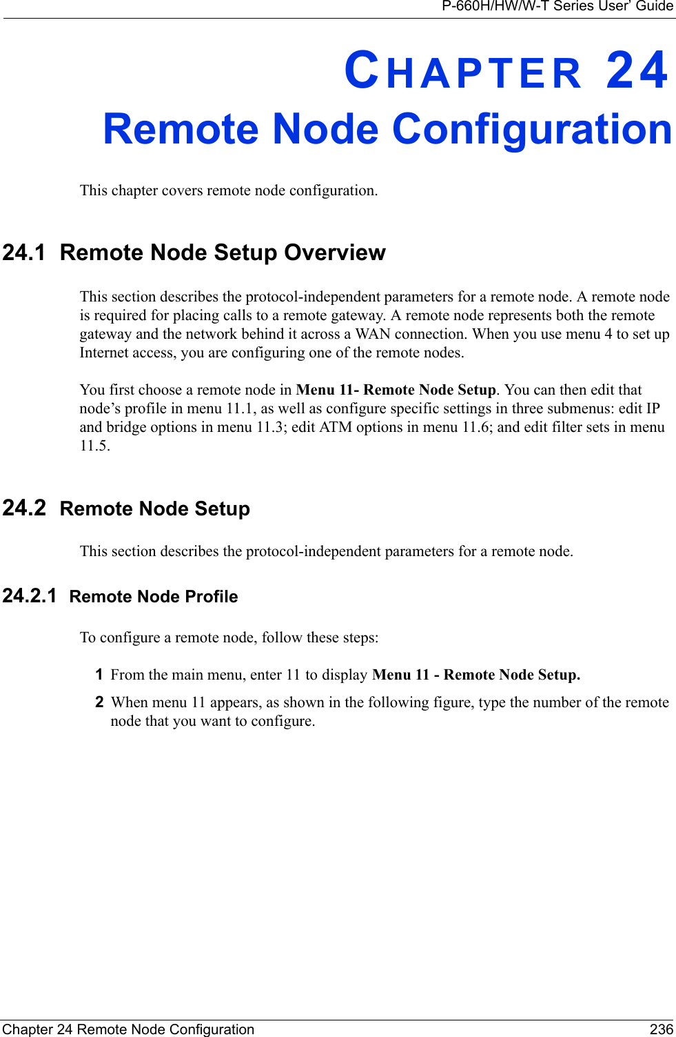
![P-660H/HW/W-T Series User’ GuideChapter 24 Remote Node Configuration 238Figure 125 Menu 11.1 Remote Node Profile In Menu 11.1 – Remote Node Profile, fill in the fields as described in the following table. Menu 11.1 - Remote Node ProfileRem Node Name= MyISP Route= IPActive= Yes Bridge= NoEncapsulation= RFC 1483 Edit IP/Bridge= NoMultiplexing= LLC-based Edit ATM Options= NoService Name= N/A Edit Advance Options= N/AIncoming: Telco Option: Rem Login= N/A Allocated Budget(min)= N/A Rem Password= N/A Period(hr)= N/AOutgoing: Schedule Sets= N/A My Login= N/A Nailed-Up Connection= N/A My Password= N/A Session Options: Authen= N/A Edit Filter Sets= No Idle Timeout(sec)= N/APress ENTER to Confirm or ESC to Cancel:Table 84 Menu 11.1 Remote Node ProfileFIELD DESCRIPTIONRem Node Name Type a unique, descriptive name of up to eight characters for this node.Active Press [SPACE BAR] and then [ENTER] to select Yes to activate or No to deactivate this node. Inactive nodes are displayed with a minus sign –“ in SMT menu 11.Encapsulation PPPoA refers to RFC-2364 (PPP Encapsulation over ATM Adaptation Layer 5). If RFC-1483 (Multiprotocol Encapsulation over ATM Adaptation Layer 5) of ENET ENCAP are selected, then the Rem Login, Rem Password, My Login, My Password and Authen fields are not applicable (N/A).Multiplexing Press [SPACE BAR] and then [ENTER] to select the method of multiplexing that your ISP uses, either VC-based or LLC-based.Service Name When using PPPoE encapsulation, type the name of your PPPoE service here. Incoming:Rem Login Type the login name that this remote node will use to call your Prestige. The login name and the Rem Password will be used to authenticate this node.Rem Password Type the password used when this remote node calls your Prestige.Outgoing:My Login Type the login name assigned by your ISP when the Prestige calls this remote node.My Password Type the password assigned by your ISP when the Prestige calls this remote node.Authen This field sets the authentication protocol used for outgoing calls. Options for this field are:CHAP/PAP – Your Prestige will accept either CHAP or PAP when requested by this remote node.CHAP – accept CHAP (Challenge Handshake Authentication Protocol) only.](https://usermanual.wiki/ZyXEL-Communications/P660HWTX.Users-Manual-3/User-Guide-566052-Page-68.png)
![P-660H/HW/W-T Series User’ Guide239 Chapter 24 Remote Node Configuration24.2.3 Outgoing Authentication ProtocolFor obvious reasons, you should employ the strongest authentication protocol possible. However, some vendors’ implementation includes specific authentication protocol in the user profile. It will disconnect if the negotiated protocol is different from that in the user profile, even when the negotiated protocol is stronger than specified. If the peer disconnects right after a successful authentication, make sure that you specify the correct authentication protocol when connecting to such an implementation.PAP – accept PAP (Password Authentication Protocol) only.Route This field determines the protocol used in routing. Options are IP and None.Bridge When bridging is enabled, your Prestige will forward any packet that it does not route to this remote node; otherwise, the packets are discarded. Select Yes to enable and No to disable.Edit IP/Bridge Press [SPACE BAR] to select Yes and press [ENTER] to display Menu 11.3 – Remote Node Network Layer Options.Edit ATM Options Press [SPACE BAR] to select Yes and press [ENTER] to display Menu 11.6 – Remote Node ATM Layer Options.Edit Advance OptionsThis field is only available when you select PPPoE in the Encapsulation field.Press [SPACE BAR] to select Yes and press [ENTER] to display Menu 11.8 – Advance Setup Options. Telco OptionAllocated Budget (min)This sets a ceiling for outgoing call time for this remote node. The default for this field is 0 meaning no budget control. Period (hr) This field is the time period that the budget should be reset. For example, if we are allowed to call this remote node for a maximum of 10 minutes every hour, then the Allocated Budget is (10 minutes) and the Period (hr) is 1 (hour).Schedule Sets This field is only applicable for PPPoE and PPPoA encapsulation. You can apply up to four schedule sets here. For more details please refer to Chapter 37 on page 338.Nailed up ConnectionThis field is only applicable for PPPoE and PPPoA encapsulation. This field specifies if you want to make the connection to this remote node a nailed-up connection. More details are given earlier in this section.Session OptionsEdit Filter Sets Use [SPACE BAR] to choose Yes and press [ENTER] to open menu 11.5 to edit the filter sets. See Chapter 29 on page 272 for more details.Idle Timeout (sec) Type the number of seconds (0-9999) that can elapse when the Prestige is idle (there is no traffic going to the remote node), before the Prestige automatically disconnects the remote node. 0 means that the session will not timeout.When you have completed this menu, press [ENTER] at the prompt “Press ENTER to Confirm or ESC to Cancel:” to save your configuration, or press [ESC] at any time to cancel.Table 84 Menu 11.1 Remote Node Profile (continued)FIELD DESCRIPTION](https://usermanual.wiki/ZyXEL-Communications/P660HWTX.Users-Manual-3/User-Guide-566052-Page-69.png)
![P-660H/HW/W-T Series User’ GuideChapter 24 Remote Node Configuration 24024.3 Remote Node Network Layer OptionsFor the TCP/IP parameters, perform the following steps to edit Menu 11.3 – Remote Node Network Layer Options as shown next.1In menu 11.1, make sure IP is among the protocols in the Route field. 2Move the cursor to the Edit IP/Bridge field, press [SPACE BAR] to select Yes, then press [ENTER] to display Menu 11.3 – Remote Node Network Layer Options.Figure 126 Menu 11.3 Remote Node Network Layer OptionsThe next table explains fields in Menu 11.3 – Remote Node Network Layer Options.Menu 11.3 - Remote Node Network Layer Options IP Options: Bridge Options: IP Address Assignment = Static Ethernet Addr Timeout(min)= N/A Rem IP Addr = 0.0.0.0 Rem Subnet Mask= 0.0.0.0 My WAN Addr= 0.0.0.0 NAT= SUA Only Address Mapping Set= N/A Metric= 2 Private= No RIP Direction= None Version= RIP-1 Multicast= None IP Policies=Enter here to CONFIRM or ESC to CANCEL:Table 85 Menu 11.3 Remote Node Network Layer OptionsFIELD DESCRIPTIONIP Address AssignmentPress [SPACE BAR] and then [ENTER] to select Dynamic if the remote node is using a dynamically assigned IP address or Static if it is using a static (fixed) IP address. You will only be able to configure this in the ISP node (also the one you configure in menu 4), all other nodes are set to Static.Rem IP Addr This is the IP address you entered in the previous menu.Rem Subnet MaskType the subnet mask assigned to the remote node.My WAN Addr Some implementations, especially UNIX derivatives, require separate IP network numbers for the WAN and LAN links and each end to have a unique address within the WAN network number. In that case, type the IP address assigned to the WAN port of your Prestige.NOTE: Refers to local Prestige address, not the remote router address.NAT Press [SPACE BAR] and then [ENTER] to select Full Feature if you have multiple public WAN IP addresses for your Prestige. Select SUA Only if you have just one public WAN IP address for your Prestige. The SMT uses Address Mapping Set 255 (seeFigure 144 on page 257). Select None to disable NAT.](https://usermanual.wiki/ZyXEL-Communications/P660HWTX.Users-Manual-3/User-Guide-566052-Page-70.png)
![P-660H/HW/W-T Series User’ Guide241 Chapter 24 Remote Node Configuration24.3.1 My WAN Addr Sample IP AddressesThe following figure uses sample IP addresses to help you understand the field of My WAN Addr in menu 11.3. My WAN Addr indicates the local Prestige WAN IP (172.16.0.1 in the following figure) while Rem IP Addr indicates the peer WAN IP (172.16.0.2 in the following figure).Address Mapping SetWhen Full Feature is selected in the NAT field, configure address mapping sets in menu 15.1. Select one of the NAT server sets (2-10) in menu 15.2 (see Chapter 27 on page 254 for details) and type that number here.When SUA Only is selected in the NAT field, the SMT uses NAT server set 1 in menu 15.2 (see Chapter 27 on page 254 for details).Metric The metric represents the cost of transmission for routing purposes. IP routing uses hop count as the cost measurement, with a minimum of 1 for directly connected networks. Type a number that approximates the cost for this link. The number need not be precise, but it must be between 1 and 15. In practice, 2 or 3 is usually a good number.Private This determines if the Prestige will include the route to this remote node in its RIP broadcasts. If set to Yes, this route is kept private and not included in RIP broadcast. If No, the route to this remote node will be propagated to other hosts through RIP broadcasts.RIP Direction Press [SPACE BAR] and then [ENTER] to select the RIP Direction. Options are Both, In Only, Out Only or None.Version Press [SPACE BAR] and then [ENTER] to select the RIP version. Options are RIP-1, RIP-2B or RIP-2M.Multicast IGMP-v1 sets IGMP to version 1, IGMP-v2 sets IGMP to version 2 and None disables IGMP.IP Policies You can apply up to four IP Policy sets (from 12) by typing in their numbers separated by commas. Configure the filter sets in menu 25 first (see Chapter 36 on page 328) and then apply them here.When you have completed this menu, press [ENTER] at the prompt “Press ENTER to Confirm or ESC to Cancel:” to save your configuration, or press [ESC] at any time to cancel.Table 85 Menu 11.3 Remote Node Network Layer Options (continued)FIELD DESCRIPTION](https://usermanual.wiki/ZyXEL-Communications/P660HWTX.Users-Manual-3/User-Guide-566052-Page-71.png)
![P-660H/HW/W-T Series User’ GuideChapter 24 Remote Node Configuration 242Figure 127 Sample IP Addresses for a TCP/IP LAN-to-LAN Connection24.4 Remote Node FilterMove the cursor to the Edit Filter Sets field in menu 11.1, then press [SPACE BAR] to select Yes. Press [ENTER] to display Menu 11.5 – Remote Node Filter.Use Menu 11.5 – Remote Node Filter to specify the filter set(s) to apply to the incoming and outgoing traffic between this remote node and the Prestige and also to prevent certain packets from triggering calls. You can specify up to 4 filter sets separated by comma, for example, 1, 5, 9, 12, in each filter field.Note that spaces are accepted in this field. The Prestige has a prepackaged filter set, NetBIOS_WAN, that blocks NetBIOS packets. Include this in the call filter sets if you want to prevent NetBIOS packets from triggering calls to a remote node.Figure 128 Menu 11.5 Remote Node Filter (RFC 1483 or ENET Encapsulation)Menu 11.5 - Remote Node Filter Input Filter Sets: protocol filters= device filters= Output Filter Sets: protocol filters= device filters=Enter here to CONFIRM or ESC to CANCEL:](https://usermanual.wiki/ZyXEL-Communications/P660HWTX.Users-Manual-3/User-Guide-566052-Page-72.png)
![P-660H/HW/W-T Series User’ Guide243 Chapter 24 Remote Node ConfigurationFigure 129 Menu 11.5 Remote Node Filter (PPPoA or PPPoE Encapsulation) 24.5 Editing ATM Layer Options Follow the steps shown next to edit Menu 11.6 – Remote Node ATM Layer Options.In menu 11.1, move the cursor to the Edit ATM Options field and then press [SPACE BAR] to select Yes. Press [ENTER] to display Menu 11.6 – Remote Node ATM Layer Options.There are two versions of menu 11.6 for the Prestige, depending on whether you chose VC-based/LLC-based multiplexing and PPP encapsulation in menu 11.1.24.5.1 VC-based Multiplexing (non-PPP Encapsulation)For VC-based multiplexing, by prior agreement, a protocol is assigned a specific virtual circuit, for example, VC1 will carry IP. Separate VPI and VCI numbers must be specified for each protocol.Figure 130 Menu 11.6 for VC-based Multiplexing24.5.2 LLC-based Multiplexing or PPP EncapsulationFor LLC-based multiplexing or PPP encapsulation, one VC carries multiple protocols with protocol identifying information being contained in each packet header. Menu 11.5 - Remote Node Filter Input Filter Sets: protocol filters= device filters= Output Filter Sets: protocol filters= device filters= Call Filter Sets: protocol filters= device filters= Enter here to CONFIRM or ESC to CANCEL:Menu 11.6 - Remote Node ATM Layer OptionsVPI/VCI (VC-Multiplexing) VC Options for IP: VPI #= 8 VCI #= 35 ATM QoS Type= UBR Peak Cell Rate (PCR)= 0 Sustain Cell Rate (SCR)= 0 Maximum Burst Size (MBS)= 0VC Options for Bridge: VPI #= 1 VCI #= 36 ATM QoS Type= N/A Peak Cell Rate (PCR)= N/A Sustain Cell Rate (SCR)= N/A Maximum Burst Size (MBR)= N/A Enter here to CONFIRM or ESC to CANCEL:](https://usermanual.wiki/ZyXEL-Communications/P660HWTX.Users-Manual-3/User-Guide-566052-Page-73.png)
![P-660H/HW/W-T Series User’ GuideChapter 24 Remote Node Configuration 244Figure 131 Menu 11.6 for LLC-based Multiplexing or PPP EncapsulationIn this case, only one set of VPI and VCI numbers need be specified for all protocols. The valid range for the VPI is 0 to 255 and for the VCI is 32 to 65535 (1 to 31 is reserved for local management of ATM traffic).24.5.3 Advance Setup OptionsIn menu 11.1, select PPPoE in the Encapsulation field. Figure 132 Menu 11.1 Remote Node ProfileMove the cursor to the Edit Advance Options field, press [SPACE BAR] to select Yes, then press [ENTER] to display Menu 11.8 – Advance Setup Options.Menu 11.6 - Remote Node ATM Layer OptionsVPI/VCI (LLC-Multiplexing or PPP-Encapsulation) VPI #= 0 VCI #= 38 ATM QoS Type= UBR Peak Cell Rate (PCR)= 0 Sustain Cell Rate (SCR)= 0 Maximum Burst Size (MBS)= 0ENTER here to CONFIRM or ESC to CANCEL: Menu 11.1 - Remote Node Profile Rem Node Name= MyISP Route= IP Active= Yes Bridge= No Encapsulation= PPPoE Edit IP/Bridge= No Multiplexing= LLC-based Edit ATM Options= No Service Name= Edit Advance Options= Yes Incoming: Telco Option: Rem Login= Allocated Budget(min)= 0 Rem Password= ******** Period(hr)= 0 Outgoing: Schedule Sets= My Login= ? Nailed-Up Connection= No My Password= ? Session Options: Authen= CHAP/PAP Edit Filter Sets= No Idle Timeout(sec)= 0 Press ENTER to Confirm or ESC to Cancel:](https://usermanual.wiki/ZyXEL-Communications/P660HWTX.Users-Manual-3/User-Guide-566052-Page-74.png)
![P-660H/HW/W-T Series User’ Guide245 Chapter 24 Remote Node ConfigurationFigure 133 Menu 11.8 Advance Setup OptionsThe following table describes the fields in this menu. Menu 11.8 - Advance Setup Options PPPoE pass-through= No Press ENTER to Confirm or ESC to Cancel:Table 86 Menu 11.8 Advance Setup OptionsFIELD DESCRIPTIONPPPoE pass-through Press [SPACE BAR] to select Yes and press [ENTER] to enable PPPoE pass through. In addition to the Prestige's built-in PPPoE client, you can enable PPPoE pass through to allow up to ten hosts on the LAN to use PPPoE client software on their computers to connect to the ISP via the Prestige. Each host can have a separate account and a public WAN IP address. PPPoE pass through is an alternative to NAT for applications where NAT is not appropriate.Press [SPACE BAR] to select No and press [ENTER] to disable PPPoE pass through if you do not need to allow hosts on the LAN to use PPPoE client software on their computers to connect to the ISP.When you have completed this menu, press [ENTER] at the prompt “Press ENTER to Confirm or ESC to Cancel:” to save your configuration, or press [ESC] at any time to cancel.](https://usermanual.wiki/ZyXEL-Communications/P660HWTX.Users-Manual-3/User-Guide-566052-Page-75.png)
![P-660H/HW/W-T Series User’ GuideChapter 25 Static Route Setup 248The following table describes the fields for Menu 12.1.1 – Edit IP Static Route Setup.Table 87 Menu12.1.1 Edit IP Static RouteFIELD DESCRIPTIONRoute # This is the index number of the static route that you chose in menu 12.1.Route Name Type a descriptive name for this route. This is for identification purpose only.Active This field allows you to activate/deactivate this static route.Destination IP Address This parameter specifies the IP network address of the final destination. Routing is always based on network number. If you need to specify a route to a single host, use a subnet mask of 255.255.255.255 in the subnet mask field to force the network number to be identical to the host ID.IP Subnet Mask Type the subnet mask for this destination.Gateway IP Address Type the IP address of the gateway. The gateway is a router or switch on the same network segment as the device’s LAN or WAN port. The gateway helps forward packets to their destinations. Metric Metric represents the cost of transmission for routing purposes. IP routing uses hop count as the measurement of cost, with a minimum of 1 for directly connected networks. Type a number that approximates the cost for this link. The number need not be precise, but it must be between 1 and 15. In practice, 2 or 3 is usually a good number.Private This parameter determines if the Prestige will include the route to this remote node in its RIP broadcasts. If set to Yes, this route is kept private and is not included in RIP broadcasts. If No, the route to this remote node will be propagated to other hosts through RIP broadcasts.When you have completed this menu, press [ENTER] at the prompt “Press ENTER to Confirm or ESC to Cancel:” to save your configuration, or press [ESC] at any time to cancel.](https://usermanual.wiki/ZyXEL-Communications/P660HWTX.Users-Manual-3/User-Guide-566052-Page-78.png)

![P-660H/HW/W-T Series User’ Guide251 Chapter 26 Bridging SetupFigure 138 Menu 11.1 Remote Node Profile3Move the cursor to the Edit IP/Bridge field, then press [SPACE BAR] to set the value to Yes and press [ENTER] to edit Menu 11.3 – Remote Node Network Layer Options.Figure 139 Menu 11.3 Remote Node Network Layer OptionsThe following table describes the fields in this menu. Menu 11.1 - Remote Node Profile Rem Node Name= ? Route= IP Active= Yes Bridge= Yes Encapsulation= ENET ENCAP Edit IP/Bridge= No Multiplexing= VC-based Edit ATM Options= No Service Name= N/A Edit Advance Options= N/A Incoming: Telco Option: Rem Login= N/A Allocated Budget(min)= N/A Rem Password= N/A Period(hr)= N/A Outgoing: Schedule Sets= N/A My Login= N/A Nailed-Up Connection= N/A My Password= N/A Session Options: Authen= N/A Edit Filter Sets= No Idle Timeout(sec)= N/APress ENTER to Confirm or ESC to Cancel:Menu 11.3 - Remote Node Network Layer Options IP Options: Bridge Options: IP Address Assignment= Static Ethernet Addr Timeout (min)= 0 Rem IP Addr: 0.0.0.0 Rem Subnet Mask= 0.0.0.0 My WAN Addr= 0.0.0.0 NAT= Full Feature Address Mapping Set=2 Metric= 2 Private= No RIP Direction= Both Version= RIP-2B Multicast= IGMP-v2 IP Policies=Press ENTER to Confirm or ESC to Cancel:Table 88 Remote Node Network Layer Options: Bridge FieldsFIELD DESCRIPTIONBridge (menu 11.1) Make sure this field is set to Yes.Edit IP/Bridge (menu 11.1) Press [SPACE BAR] to select Yes and press [ENTER] to display menu 11.3.Ethernet Addr Timeout(min.) (menu 11.3)Type the time (in minutes) for the Prestige to retain the Ethernet Address information in its internal tables while the line is down. If this information is retained, your Prestige will not have to recompile the tables when the line comes back up.](https://usermanual.wiki/ZyXEL-Communications/P660HWTX.Users-Manual-3/User-Guide-566052-Page-81.png)
![P-660H/HW/W-T Series User’ GuideChapter 26 Bridging Setup 25226.2.2 Bridge Static Route SetupSimilar to network layer static routes, a bridging static route tells the Prestige the route to a node before a connection is established. You configure bridge static routes in menu 12.3.1 (go to menu 12, choose option 3, then choose a static route to edit) as shown next.Figure 140 Menu 12.3.1 Edit Bridge Static RouteThe following table describes the Edit Bridge Static Route menu.Menu 12.3.1 - Edit Bridge Static RouteRoute #: 1Route Name=Active= NoEther Address= ?IP Address=Gateway Node= 1Press ENTER to Confirm or ESC to Cancel:Table 89 Menu 12.3.1 Edit Bridge Static RouteFIELD DESCRIPTIONRoute # This is the route index number you typed in Menu 12.3 – Bridge Static Route Setup.Route Name Type a name for the bridge static route for identification purposes.Active Indicates whether the static route is active (Yes) or not (No).Ether Address Type the MAC address of the destination computer that you want to bridge the packets to.IP Address If available, type the IP address of the destination computer that you want to bridge the packets to.Gateway Node Press [SPACE BAR] and then [ENTER] to select the number of the remote node (one to eight) that is the gateway of this static route.When you have completed this menu, press [ENTER] at the prompt “Press ENTER to Confirm or ESC to Cancel:” to save your configuration, or press [ESC] at any time to cancel.](https://usermanual.wiki/ZyXEL-Communications/P660HWTX.Users-Manual-3/User-Guide-566052-Page-82.png)

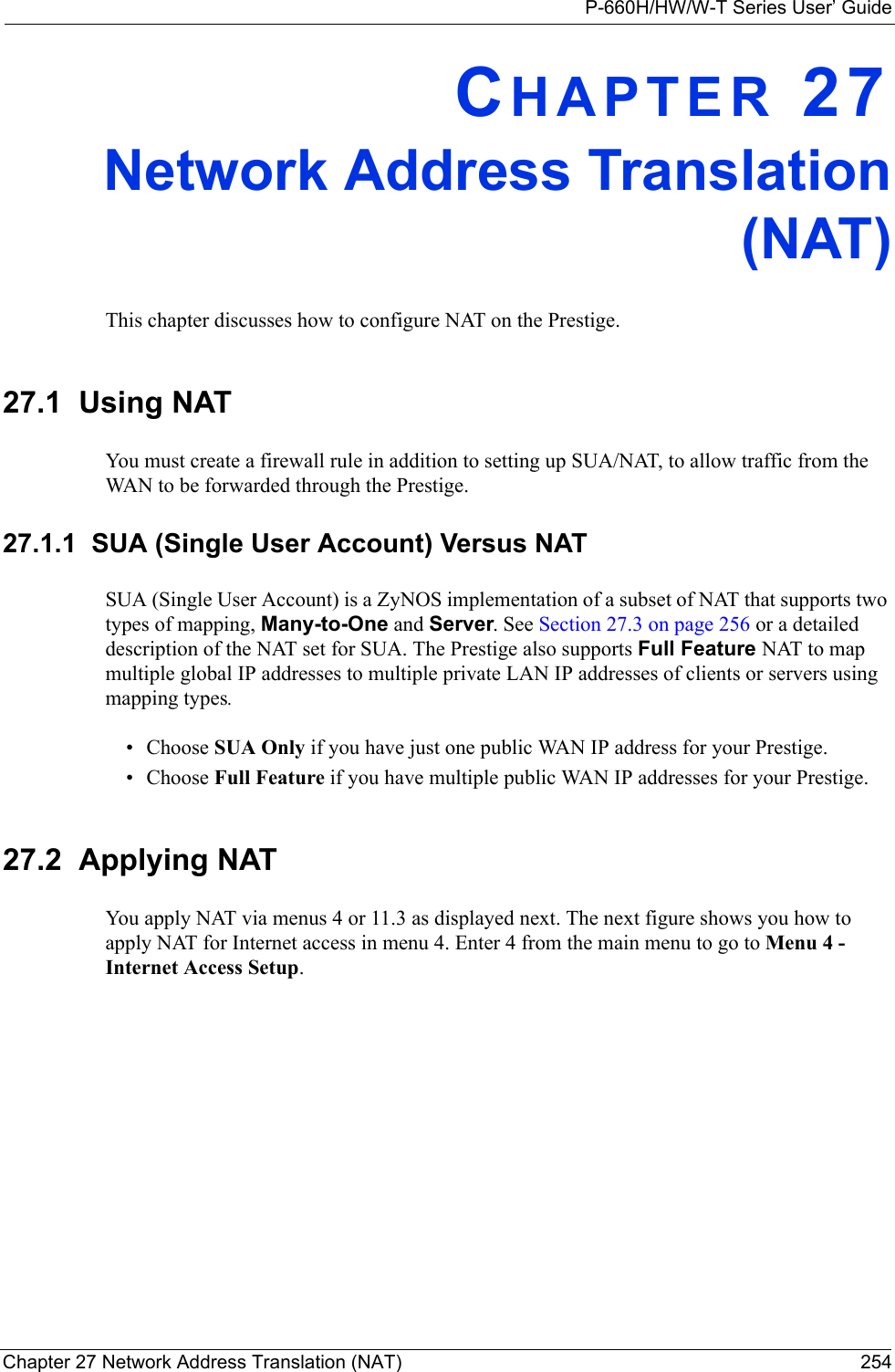
![P-660H/HW/W-T Series User’ Guide255 Chapter 27 Network Address Translation (NAT)Figure 141 Menu 4 Applying NAT for Internet AccessThe following figure shows how you apply NAT to the remote node in menu 11.1. 1Enter 11 from the main menu.2When menu 11 appears, as shown in the following figure, type the number of the remote node that you want to configure.3Move the cursor to the Edit IP/Bridge field, press [SPACE BAR] to select Yes and then press [ENTER] to bring up Menu 11.3 - Remote Node Network Layer Options.Figure 142 Applying NAT in Menus 4 & 11.3The following table describes the options for Network Address Translation.Menu 4 - Internet Access Setup ISP's Name= MyISP Encapsulation= RFC 1483 Multiplexing= LLC-based VPI #= 8 VCI #= 35 ATM QoS Type= UBR Peak Cell Rate (PCR)= 0 Sustain Cell Rate (SCR)= 0 Maximum Burst Size (MBS)= 0 My Login= N/A My Password= N/A ENET ENCAP Gateway= N/A IP Address Assignment= Static IP Address= 0.0.0.0 Network Address Translation= SUA Only Address Mapping Set= N/APress ENTER to Confirm or ESC to Cancel:Menu 11.3 - Remote Node Network Layer OptionsIP Options: Bridge Options: IP Address Assignment = Static Ethernet Addr Timeout(min)= N/A Rem IP Addr = 0.0.0.0 Rem Subnet Mask= 0.0.0.0 My WAN Addr= 0.0.0.0 NAT= SUA Only Address Mapping Set= N/A Metric= 2 Private= No RIP Direction= Both Version= RIP-2B Multicast= None IP Policies=Enter here to CONFIRM or ESC to CANCEL:](https://usermanual.wiki/ZyXEL-Communications/P660HWTX.Users-Manual-3/User-Guide-566052-Page-85.png)
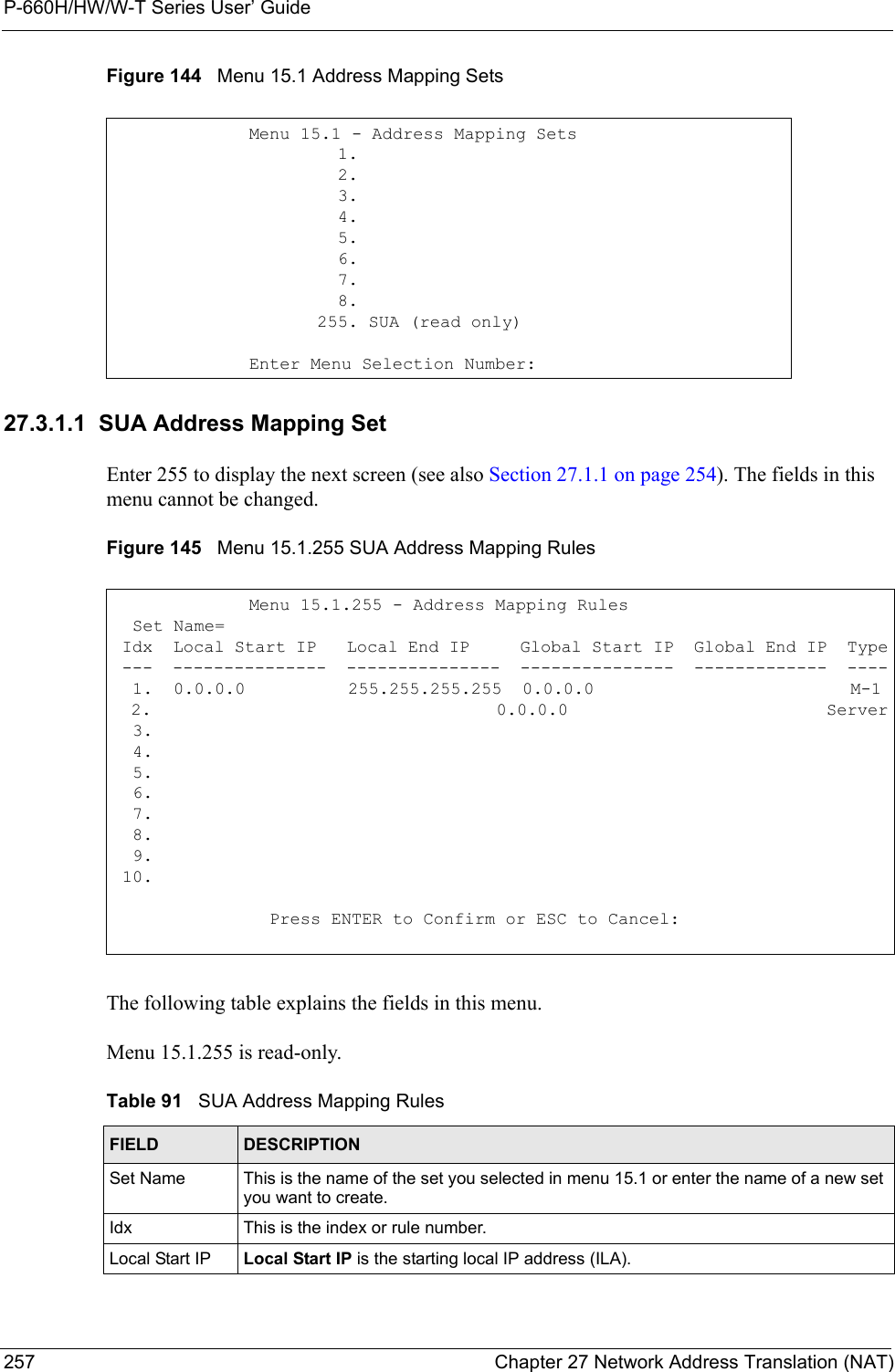
![P-660H/HW/W-T Series User’ GuideChapter 27 Network Address Translation (NAT) 25627.3 NAT SetupUse the address mapping sets menus and submenus to create the mapping table used to assign global addresses to computers on the LAN. Set 255 is used for SUA. When you select Full Feature in menu 4 or 11.3, the SMT will use Set 1. When you select SUA Only, the SMT will use the pre-configured Set 255 (read only).The server set is a list of LAN servers mapped to external ports. To use this set, a server rule must be set up inside the NAT address mapping set. Please see the web configurator NAT chapter for further information on these menus. To configure NAT, enter 15 from the main menu to bring up the following screen. Figure 143 Menu 15 NAT Setup 27.3.1 Address Mapping Sets Enter 1 to bring up Menu 15.1 — Address Mapping Sets.Table 90 Applying NAT in Menus 4 & 11.3FIELD DESCRIPTIONNAT Press [SPACE BAR] and then [ENTER] to select Full Feature if you have multiple public WAN IP addresses for your Prestige. The SMT uses the address mapping set that you configure and enter in the Address Mapping Set field (seeFigure 144 on page 257). Select None to disable NAT.When you select SUA Only, the SMT uses Address Mapping Set 255 (seeFigure 145 on page 257). Choose SUA Only if you have just one public WAN IP address for your Prestige.Menu 15 - NAT Setup 1. Address Mapping Sets 2. NAT Server SetsEnter Menu Selection Number:](https://usermanual.wiki/ZyXEL-Communications/P660HWTX.Users-Manual-3/User-Guide-566052-Page-86.png)
![P-660H/HW/W-T Series User’ GuideChapter 27 Network Address Translation (NAT) 25827.3.1.2 User-Defined Address Mapping SetsNow let’s look at option 1 in menu 15.1. Enter 1 to bring up this menu. We’ll just look at the differences from the previous menu. Note the extra Action and Select Rule fields mean you can configure rules in this screen. Note also that the [?] in the Set Name field means that this is a required field and you must enter a name for the set.Figure 146 Menu 15.1.1 First SetIf the Set Name field is left blank, the entire set will be deleted.The Type, Local and Global Start/End IPs are configured in menu 15.1.1.1 (described later) and the values are displayed here.Local End IP Local End IP is the ending local IP address (ILA). If the rule is for all local IPs, then the Start IP is 0.0.0.0 and the End IP is 255.255.255.255.Global Start IP This is the starting global IP address (IGA). If you have a dynamic IP, enter 0.0.0.0 as the Global Start IP.Global End IP This is the ending global IP address (IGA).Type These are the mapping types. Server allows us to specify multiple servers of different types behind NAT to this machine. See later for some examples.When you have completed this menu, press [ENTER] at the prompt “Press ENTER to Confirm or ESC to Cancel:” to save your configuration, or press [ESC] at any time to cancel.Table 91 SUA Address Mapping Rules (continued)FIELD DESCRIPTIONMenu 15.1.1 - Address Mapping Rules Set Name= NAT_SET Idx Local Start IP Local End IP Global Start IP Global End IP Type --- --------------- --------------- --------------- --------=----- --- 1. 2 3. 4. 5. 6. 7. 8. 9. 10.Action= Edit Select Rule=Press ENTER to Confirm or ESC to Cancel:](https://usermanual.wiki/ZyXEL-Communications/P660HWTX.Users-Manual-3/User-Guide-566052-Page-88.png)
![P-660H/HW/W-T Series User’ Guide259 Chapter 27 Network Address Translation (NAT)27.3.1.3 Ordering Your RulesOrdering your rules is important because the Prestige applies the rules in the order that you specify. When a rule matches the current packet, the Prestige takes the corresponding action and the remaining rules are ignored. If there are any empty rules before your new configured rule, your configured rule will be pushed up by that number of empty rules. For example, if you have already configured rules 1 to 6 in your current set and now you configure rule number 9. In the set summary screen, the new rule will be rule 7, not 9. Now if you delete rule 4, rules 5 to 7 will be pushed up by 1 rule, so as old rule 5 becomes rule 4, old rule 6 becomes rule 5 and old rule 7 becomes rule 6. You must press [ENTER] at the bottom of the screen to save the whole set. You must do this again if you make any changes to the set – including deleting a rule. No changes to the set take place until this action is taken. Selecting Edit in the Action field and then selecting a rule brings up the following menu, Menu 15.1.1.1 - Address Mapping Rule in which you can edit an individual rule and configure the Type, Local and Global Start/End IPs.An End IP address must be numerically greater than its corresponding IP Start address.Figure 147 Menu 15.1.1.1 Editing/Configuring an Individual Rule in a Set Table 92 Menu 15.1.1 First SetFIELD DESCRIPTIONSet Name Enter a name for this set of rules. This is a required field. If this field is left blank, the entire set will be deleted.Action The default is Edit. Edit means you want to edit a selected rule (see following field). Insert Before means to insert a rule before the rule selected. The rules after the selected rule will then be moved down by one rule. Delete means to delete the selected rule and then all the rules after the selected one will be advanced one rule. None disables the Select Rule item.Select Rule When you choose Edit, Insert Before or Delete in the previous field the cursor jumps to this field to allow you to select the rule to apply the action in question.Menu 15.1.1.1 Address Mapping Rule Type= One-to-One Local IP: Start= End = N/A Global IP: Start= End = N/A Server Mapping Set= N/APress ENTER to Confirm or ESC to Cancel:](https://usermanual.wiki/ZyXEL-Communications/P660HWTX.Users-Manual-3/User-Guide-566052-Page-89.png)
![P-660H/HW/W-T Series User’ GuideChapter 27 Network Address Translation (NAT) 260The following table explains the fields in this menu.27.4 Configuring a Server behind NATFollow these steps to configure a server behind NAT:1Enter 15 in the main menu to go to Menu 15 - NAT Setup.2Enter 2 to display Menu 15.2 - NAT Server Sets as shown next.Figure 148 Menu 15.2 NAT Server Setup3Enter 1 to go to Menu 15.2.1 NAT Server Setup as follows.Table 93 Menu 15.1.1.1 Editing/Configuring an Individual Rule in a SetFIELD DESCRIPTIONType Press [SPACE BAR] and then [ENTER] to select from a total of five types. These are the mapping types discussed in the web configurator NAT chapter. Server allows you to specify multiple servers of different types behind NAT to this computer.Local IP Only local IP fields are N/A for server; Global IP fields MUST be set for Server.Start This is the starting local IP address (ILA).End This is the ending local IP address (ILA). If the rule is for all local IPs, then put the Start IP as 0.0.0.0 and the End IP as 255.255.255.255. This field is N/A for One-to-One and Server types.Global IPStart This is the starting inside global IP address (IGA). If you have a dynamic IP, enter 0.0.0.0 as the Global IP Start. Note that Global IP Start can be set to 0.0.0.0 only if the types are Many-to-One or Server.End This is the ending inside global IP address (IGA). This field is N/A for One-to-One, Many-to-One and Server types.Server Mapping SetOnly available when Type is set to Server. Type a number from 1 to 10 to choose a server set from menu 15.2.When you have completed this menu, press [ENTER] at the prompt “Press ENTER to Confirm or ESC to Cancel:” to save your configuration, or press [ESC] at any time to cancel.Menu 15.2 - NAT Server Sets 1. Server Set 1 (Used for SUA Only) 2. Server Set 2 3. Server Set 3 4. Server Set 4 5. Server Set 5 6. Server Set 6 7. Server Set 7 8. Server Set 8 9. Server Set 9 10. Server Set 10 Enter Set Number to Edit:](https://usermanual.wiki/ZyXEL-Communications/P660HWTX.Users-Manual-3/User-Guide-566052-Page-90.png)
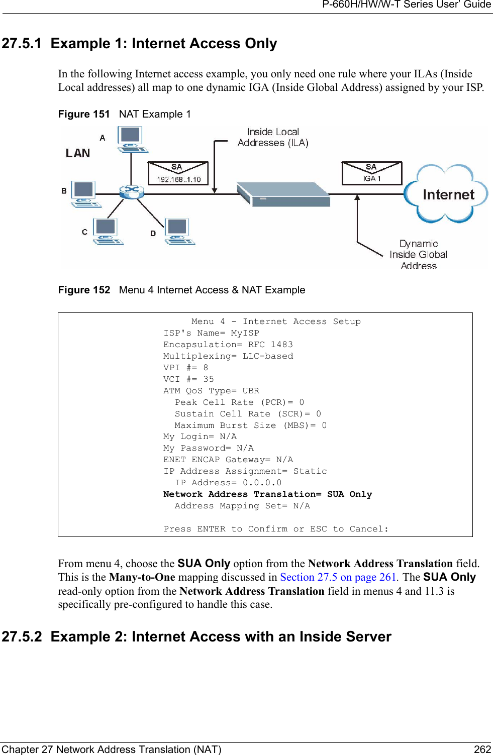
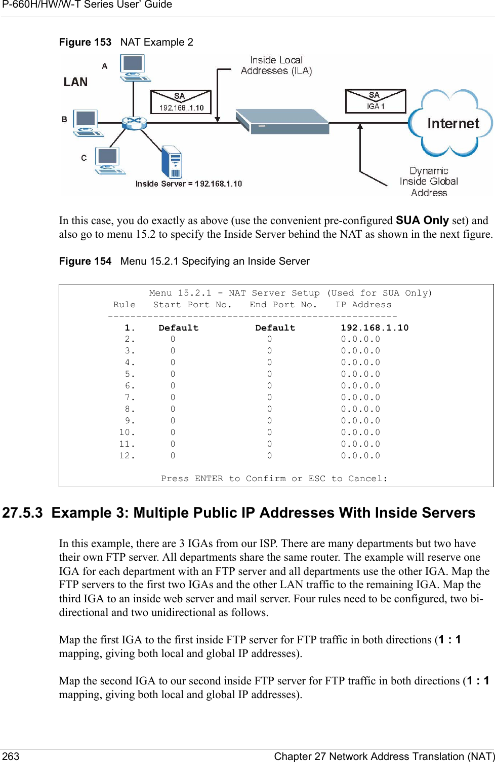
![P-660H/HW/W-T Series User’ Guide261 Chapter 27 Network Address Translation (NAT)Figure 149 Menu 15.2.1 NAT Server Setup4Enter a port number in an unused Start Port No field. To forward only one port, enter it again in the End Port No field. To specify a range of ports, enter the last port to be forwarded in the End Port No field. 5Enter the inside IP address of the server in the IP Address field. In the following figure, you have a computer acting as an FTP, Telnet and SMTP server (ports 21, 23 and 25) at 192.168.1.33.6Press [ENTER] at the “Press ENTER to confirm ...” prompt to save your configuration after you define all the servers or press [ESC] at any time to cancel.Figure 150 Multiple Servers Behind NAT Example27.5 General NAT ExamplesThe following are some examples of NAT configuration.Menu 15.2 - NAT Server Setup Rule Start Port No. End Port No. IP Address --------------------------------------------------- 1. Default Default 0.0.0.0 2. 21 21 192.168.1.33 3. 0 0 0.0.0.0 4. 0 0 0.0.0.0 5. 0 0 0.0.0.0 6. 0 0 0.0.0.0 7. 0 0 0.0.0.0 8. 0 0 0.0.0.0 9. 0 0 0.0.0.0 10. 0 0 0.0.0.0 11. 0 0 0.0.0.0 12. 0 0 0.0.0.0Press ENTER to Confirm or ESC to Cancel:](https://usermanual.wiki/ZyXEL-Communications/P660HWTX.Users-Manual-3/User-Guide-566052-Page-91.png)
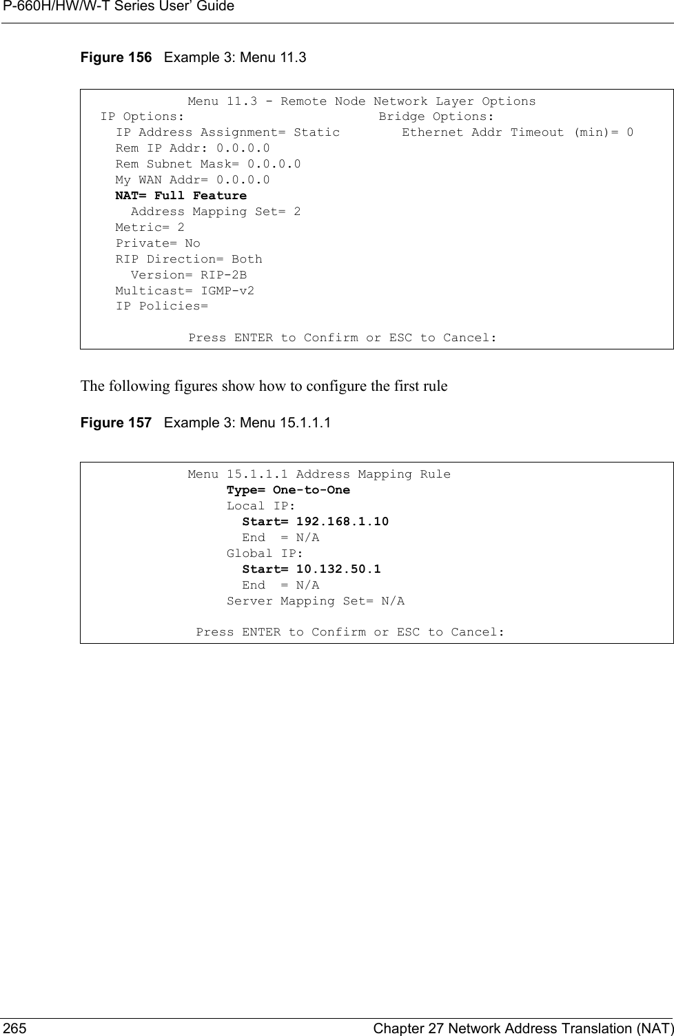
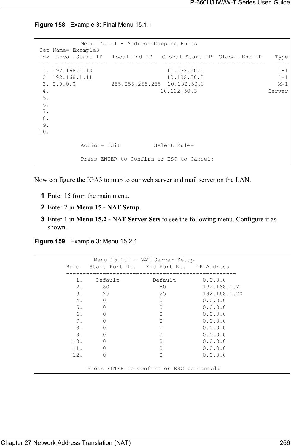
![P-660H/HW/W-T Series User’ GuideChapter 27 Network Address Translation (NAT) 264Map the other outgoing LAN traffic to IGA3 (Many : 1 mapping).You also map your third IGA to the web server and mail server on the LAN. Type Server allows you to specify multiple servers, of different types, to other computers behind NAT on the LAN. The example situation looks somewhat like this:Figure 155 NAT Example 3In this case you need to configure Address Mapping Set 1 from Menu 15.1 - Address Mapping Sets. Therefore you must choose the Full Feature option from the Network Address Translation field (in menu 4 or menu 11.3) inFigure 156 on page 265. 1Enter 15 from the main menu.2Enter 1 to configure the Address Mapping Sets.3Enter 1 to begin configuring this new set. Enter a Set Name, choose the Edit Action and then enter 1 for the Select Rule field. Press [ENTER] to confirm.4Select Type as One-to-One (direct mapping for packets going both ways), and enter the local Start IP as 192.168.1.10 (the IP address of FTP Server 1), the global Start IP as 10.132.50.1 (our first IGA). (SeeFigure 157 on page 265).5Repeat the previous step for rules 2 to 4 as outlined above. When finished, menu 15.1.1 should look like as shown inFigure 158 on page 266.](https://usermanual.wiki/ZyXEL-Communications/P660HWTX.Users-Manual-3/User-Guide-566052-Page-94.png)
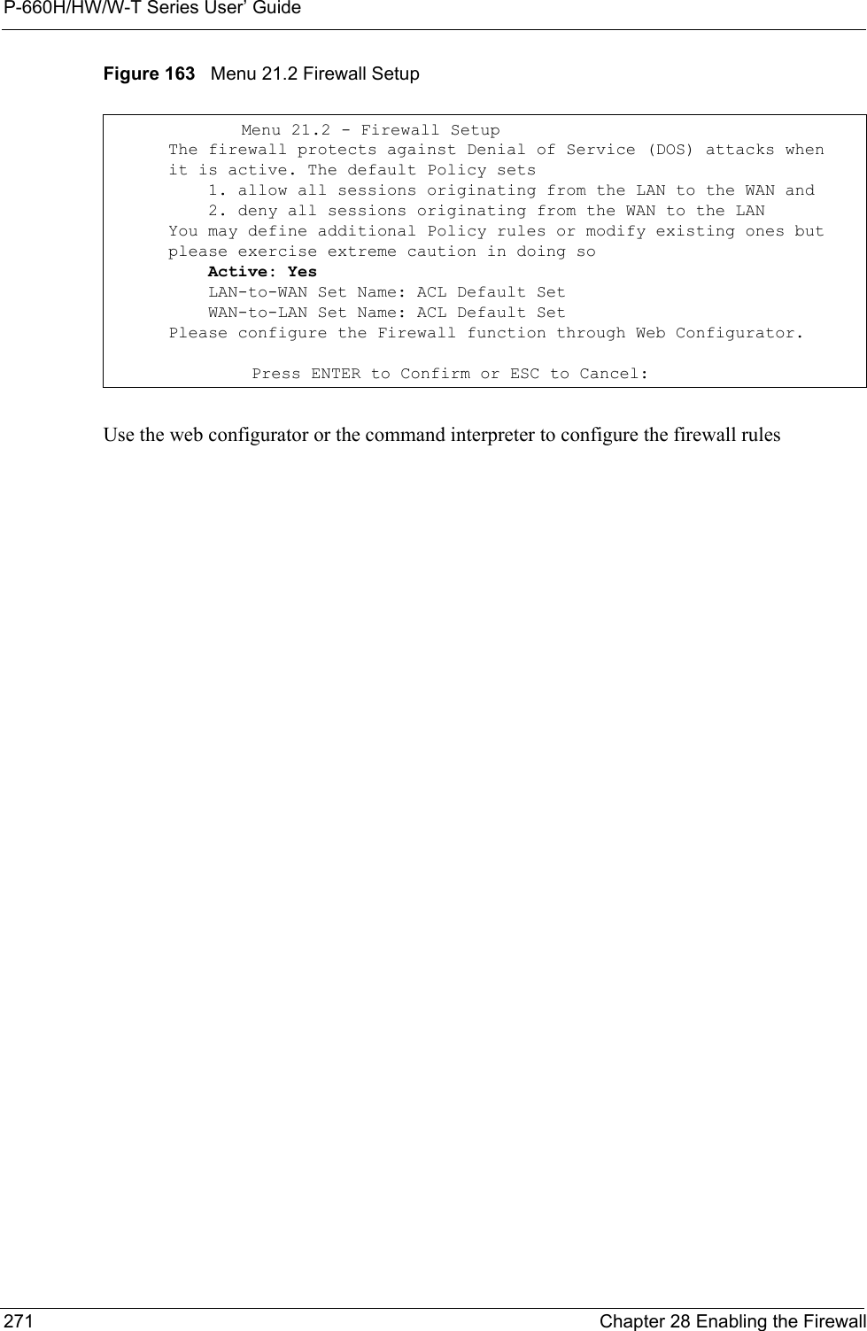
![P-660H/HW/W-T Series User’ GuideChapter 28 Enabling the Firewall 270CHAPTER 28Enabling the FirewallThis chapter shows you how to get started with the Prestige firewall.28.1 Remote Management and the FirewallWhen SMT menu 24.11 is configured to allow management and the firewall is enabled:• The firewall blocks remote management from the WAN unless you configure a firewall rule to allow it.• The firewall allows remote management from the LAN. 28.2 Access MethodsThe web configurator is, by far, the most comprehensive firewall configuration tool your Prestige has to offer. For this reason, it is recommended that you configure your firewall using the web configurator, see the following chapters for instructions. SMT screens allow you to activate the firewall and view firewall logs. 28.3 Enabling the FirewallFrom the main menu enter 21 to go to Menu 21 - Filter Set and Firewall Configuration to display the screen shown next.Enter option 2 in this menu to bring up the following screen. Press [SPACE BAR] and then [ENTER] to select Yes in the Active field to activate the firewall. The firewall must be active to protect against Denial of Service (DoS) attacks. Additional rules may be configured using the web configurator.](https://usermanual.wiki/ZyXEL-Communications/P660HWTX.Users-Manual-3/User-Guide-566052-Page-100.png)
![P-660H/HW/W-T Series User’ GuideChapter 29 Filter Configuration 27429.2 Configuring a Filter Set for the Prestige To configure a filter set, follow the steps shown next.1Enter 21 in the main menu to display Menu 21 – Filter and Firewall Setup.2Enter 1 to display Menu 21.1 – Filter Set Configuration as shown next.Figure 166 Menu 21 Filter Set Configuration3Type the filter set to configure (no. 1 to 12) and press [ENTER].4Type a descriptive name or comment in the Edit Comments field and press [ENTER].5Press [ENTER] at the message “Press ENTER to confirm…” to display Menu 21.1.1 – Filter Rules Summary (that is, if you selected filter set 1 in menu 21.1).Figure 167 NetBIOS_WAN Filter Rules Summary Menu 21.1 - Filter Set Configuration Filter Set # Comments Set # Comments ------ ----------------- ------ ----------------- 1 _______________ 7 _______________ 2 _______________ 8 _______________ 3 _______________ 9 _______________ 4 _______________ 10 _______________ 5 _______________ 11 _______________ 6 _______________ 12 _______________Enter Filter Set Number to Configure= 0Edit Comments= N/APress ENTER to Confirm or ESC to Cancel:Menu 21.1.2 - Filter Rules Summary # A Type Filter Rules M m n - - ---- --------------------------------------------------------------- - - - 1 Y IP Pr=6, SA=0.0.0.0, DA=0.0.0.0, DP=137 N D N 2 Y IP Pr=6, SA=0.0.0.0, DA=0.0.0.0, DP=138 N D N 3 Y IP Pr=6, SA=0.0.0.0, DA=0.0.0.0, DP=139 N D N 4 Y IP Pr=17, SA=0.0.0.0, DA=0.0.0.0, DP=137 N D N 5 Y IP Pr=17, SA=0.0.0.0, DA=0.0.0.0, DP=138 N D N 6 Y IP Pr=17, SA=0.0.0.0, DA=0.0.0.0, DP=139 N D FEnter Filter Rule Number (1-6) to Configure:](https://usermanual.wiki/ZyXEL-Communications/P660HWTX.Users-Manual-3/User-Guide-566052-Page-104.png)
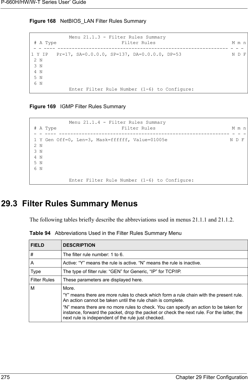
![P-660H/HW/W-T Series User’ GuideChapter 29 Filter Configuration 276The protocol dependent filter rules abbreviation are listed as follows:29.4 Configuring a Filter RuleTo configure a filter rule, type its number in Menu 21.1.x – Filter Rules Summary and press [ENTER] to open menu 21.1.x.1 for the rule.There are two types of filter rules: TCP/IP and Generic. Depending on the type of rule, the parameters for each type will be different. Use [SPACE BAR] to select the type of rule that you want to create in the Filter Type field and press [ENTER] to open the respective menu.To speed up filtering, all rules in a filter set must be of the same class, for instance, protocol filters or generic filters. The class of a filter set is determined by the first rule that you create. When applying the filter sets to a port, separate menu fields are provided for protocol and device filter sets. If you include a protocol filter set in a device filters field or vice versa, the Prestige will warn you and will not allow you to save.mAction Matched.“F” means to forward the packet immediately and skip checking the remaining rules.“D” means to drop the packet.“N“means to check the next rule.nAction Not Matched.“F” means to forward the packet immediately and skip checking the remaining rules.“D” means to drop the packet.“N” means to check the next rule.Table 95 Rule Abbreviations UsedFILTER TYPE DESCRIPTIONIPPr ProtocolSA Source AddressSP Source Port NumberDA Destination AddressDP Destination Port NumberGENOff OffsetLen LengthTable 94 Abbreviations Used in the Filter Rules Summary Menu (continued)FIELD DESCRIPTION](https://usermanual.wiki/ZyXEL-Communications/P660HWTX.Users-Manual-3/User-Guide-566052-Page-106.png)
![P-660H/HW/W-T Series User’ Guide277 Chapter 29 Filter Configuration29.4.1 TCP/IP Filter RuleThis section shows you how to configure a TCP/IP filter rule. TCP/IP rules allow you to base the rule on the fields in the IP and the upper layer protocol, for example, UDP and TCP headers.To configure TCP/IP rules, select TCP/IP Filter Rule from the Filter Type field and press [ENTER] to open Menu 21.1.x.1 – TCP/IP Filter Rule, as shown next.Figure 170 Menu 21.1.x.1 TCP/IP Filter RuleThe following table describes how to configure your TCP/IP filter rule. Menu 21.1.1.1 - TCP/IP Filter Rule Filter #: 1,1 Filter Type= TCP/IP Filter Rule Active= No IP Protocol= 0 IP Source Route= No Destination: IP Addr= IP Mask= Port #= Port # Comp= None Source: IP Addr= IP Mask= Port #= Port # Comp= None TCP Estab= N/A More= No Log= None Action Matched= Check Next Rule Action Not Matched= Check Next Rule Press ENTER to Confirm or ESC to Cancel:Table 96 Menu 21.1.x.1 TCP/IP Filter RuleFIELD DESCRIPTIONFilter # This is the filter set, filter rule coordinates, for instance, 2, 3 refers to the second filter set and the third filter rule of that set.Filter Type Use [SPACE BAR] and then [ENTER] to choose a rule. Parameters displayed for each type will be different. Choices are TCP/IP Filter Rule or Generic Filter Rule.Active Select Yes to activate or No to deactivate the filter rule.IP Protocol This is the upper layer protocol, for example, TCP is 6, UDP is 17 and ICMP is 1. The value must be between 0 and 255. A value of 0 matches ANY protocol.IP Source Route IP Source Route is an optional header that dictates the route an IP packet takes from its source to its destination. If Yes, the rule applies to any packet with an IP source route. The majority of IP packets do not have source route.Destination:IP Addr Type the destination IP address of the packet you want to filter. This field is ignored if it is 0.0.0.0.IP Mask Type the IP mask to apply to the Destination: IP Addr field.](https://usermanual.wiki/ZyXEL-Communications/P660HWTX.Users-Manual-3/User-Guide-566052-Page-107.png)
![P-660H/HW/W-T Series User’ GuideChapter 29 Filter Configuration 278The following figure illustrates the logic flow of an IP filter.Port # Type the destination port of the packets you want to filter. The field range is 0 to 65535. A 0 field is ignored.Port # Comp Select the comparison to apply to the destination port in the packet against the value given in Destination: Port #. Choices are None, Less, Greater, Equal or Not Equal.Source:IP Addr Type the source IP Address of the packet you want to filter. A 0.0.0.0 field is ignored.IP Mask Type the IP mask to apply to the Source: IP Addr field.Port # Type the source port of the packets you want to filter. The range of this field is 0 to 65535. A 0 field is ignored.Port # Comp Select the comparison to apply to the source port in the packet against the value given in Source: Port # field. Choices are None, Less, Greater, Equal or Not Equal.TCP Estab This applies only when the IP Protocol field is 6, TCP. If Yes, the rule matches packets that want to establish TCP connection(s) (SYN=1 and ACK=0); else it is ignored.More If Yes, a matching packet is passed to the next filter rule before an action is taken or else the packet is disposed of according to the action fields.If More is Yes, then Action Matched and Action Not Matched will be N/A.Log Select the logging option from the following:None – No packets will be logged.Action Matched – Only packets that match the rule parameters will be logged.Action Not Matched – Only packets that do not match the rule parameters will be logged.Both – All packets will be logged.Action Matched Select the action for a matching packet. Choices are Check Next Rule, Forward or Drop.Action Not MatchedSelect the action for a packet not matching the rule. Choices are Check Next Rule, Forward or Drop.When you have completed this menu, press [ENTER] at the prompt “Press ENTER to Confirm or ESC to Cancel:” to save your configuration, or press [ESC] at any time to cancel.Table 96 Menu 21.1.x.1 TCP/IP Filter Rule (continued)FIELD DESCRIPTION](https://usermanual.wiki/ZyXEL-Communications/P660HWTX.Users-Manual-3/User-Guide-566052-Page-108.png)
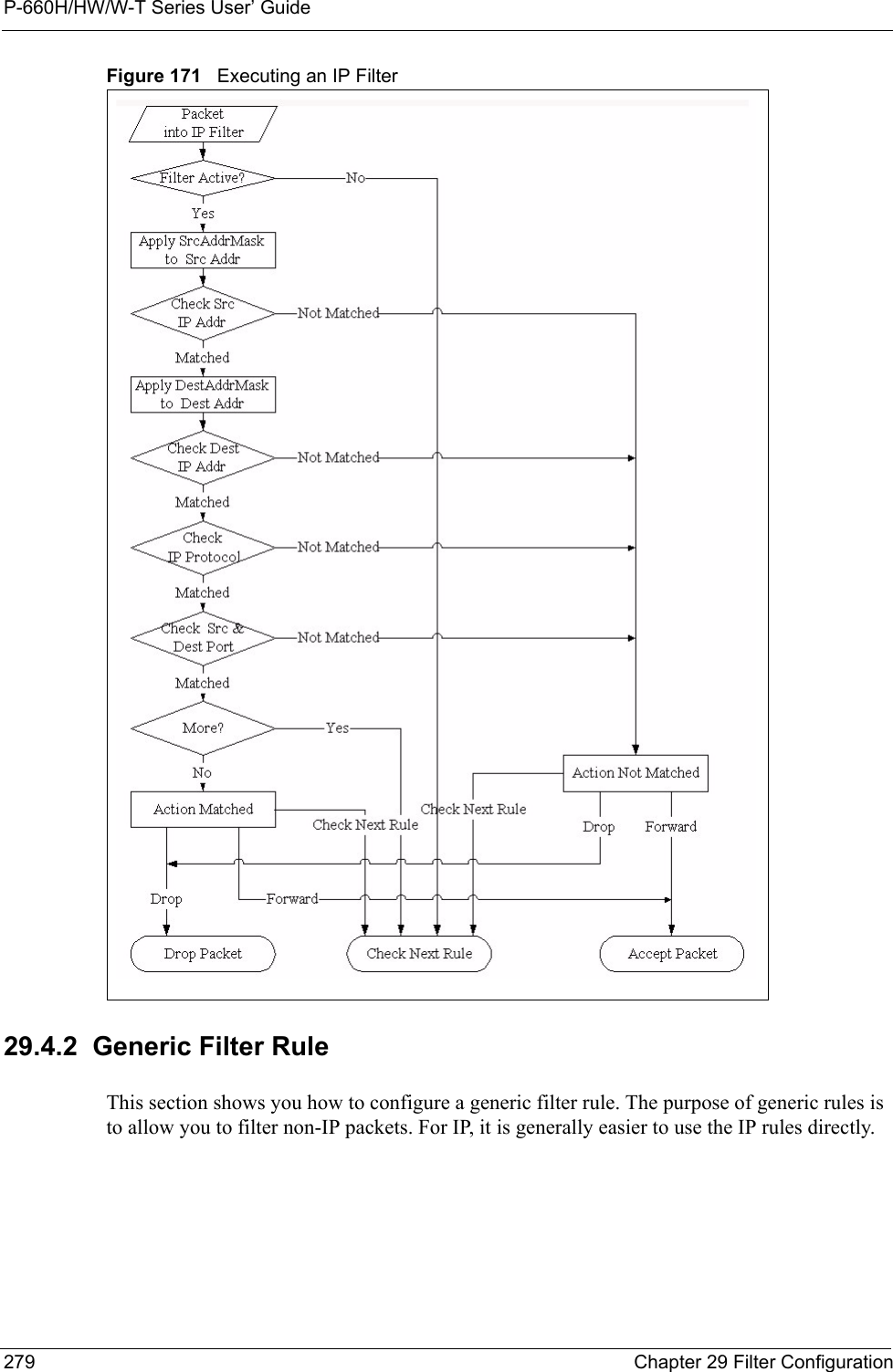
![P-660H/HW/W-T Series User’ GuideChapter 29 Filter Configuration 280For generic rules, the Prestige treats a packet as a byte stream as opposed to an IP packet. You specify the portion of the packet to check with the Offset (from 0) and the Length fields, both in bytes. The Prestige applies the Mask (bit-wise ANDing) to the data portion before comparing the result against the Value to determine a match. The Mask and Value fields are specified in hexadecimal numbers. Note that it takes two hexadecimal digits to represent a byte, so if the length is 4, the value in either field will take 8 digits, for example, FFFFFFFF. To configure a generic rule select an empty filter set in menu 21, for example 5. Select Generic Filter Rule in the Filter Type field and press [ENTER] to open Menu 21.1.5.1 – Generic Filter Rule, as shown in the following figure.Figure 172 Menu 21.1.5.1 Generic Filter Rule The next table describes the fields in the Generic Filter Rule menu.Menu 21.1.5.1 - Generic Filter RuleFilter #: 5,1Filter Type= Generic Filter RuleActive= NoOffset= 0Length= 0Mask= N/AValue= N/AMore= No Log= NoneAction Matched= Check Next RuleAction Not Matched= Check Next RulePress ENTER to Confirm or ESC to Cancel:Table 97 Menu 21.1.5.1 Generic Filter RuleFIELD DESCRIPTIONFilter # This is the filter set, filter rule coordinates, for instance, 2, 3 refers to the second filter set and the third rule of that set.Filter Type Press [SPACE BAR] and then [ENTER] to select a type of rule. Parameters displayed below each type will be different. Choices are Generic Filter Rule or TCP/IP Filter Rule.Active Select Yes to turn on or No to turn off the filter rule.Offset Type the starting byte of the data portion in the packet that you want to compare. The range for this field is from 0 to 255.Length Type the byte count of the data portion in the packet that you want to compare. The range for this field is 0 to 8.Mask Type the mask (in Hexadecimal) to apply to the data portion before comparison.Value Type the value (in Hexadecimal) to compare with the data portion.More If Yes, a matching packet is passed to the next filter rule before an action is taken or else the packet is disposed of according to the action fields.If More is Yes, then Action Matched and Action Not Matched will be N/A.](https://usermanual.wiki/ZyXEL-Communications/P660HWTX.Users-Manual-3/User-Guide-566052-Page-110.png)
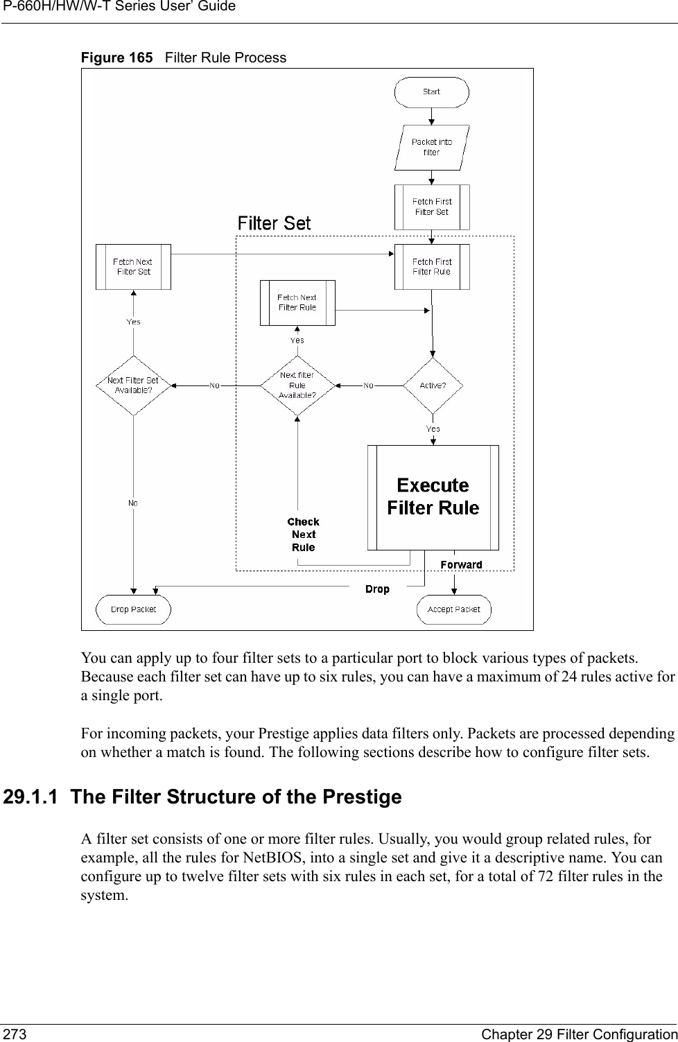
![P-660H/HW/W-T Series User’ Guide281 Chapter 29 Filter Configuration29.5 Filter Types and NAT There are two classes of filter rules, Generic Filter Device rules and Protocol Filter (TCP/IP) rules. Generic Filter rules act on the raw data from/to LAN and WAN. Protocol Filter rules act on IP packets.When NAT (Network Address Translation) is enabled, the inside IP address and port number are replaced on a connection-by-connection basis, which makes it impossible to know the exact address and port on the wire. Therefore, the Prestige applies the protocol filters to the “native” IP address and port number before NAT for outgoing packets and after NAT for incoming packets. On the other hand, the generic (or device) filters are applied to the raw packets that appear on the wire. They are applied at the point where the Prestige is receiving and sending the packets; for instance, the interface. The interface can be an Ethernet, or any other hardware port. The following figure illustrates this.Figure 173 Protocol and Device Filter Sets29.6 Example FilterLet’s look at an example to block outside users from telnetting into the Prestige. Log Select the logging option from the following:None – No packets will be logged.Action Matched – Only matching packets and rules will be logged.Action Not Matched – Only packets that do not match the rule parameters will be logged.Both – All packets will be logged.Action MatchedSelect the action for a matching packet. Choices are Check Next Rule, Forward or Drop.Action Not MatchedSelect the action for a packet not matching the rule. Choices are Check Next Rule, Forward or Drop.When you have completed this menu, press [ENTER] at the prompt “Press ENTER to Confirm or ESC to Cancel:” to save your configuration, or press [ESC] at any time to cancel.Table 97 Menu 21.1.5.1 Generic Filter Rule (continued)FIELD DESCRIPTION](https://usermanual.wiki/ZyXEL-Communications/P660HWTX.Users-Manual-3/User-Guide-566052-Page-111.png)
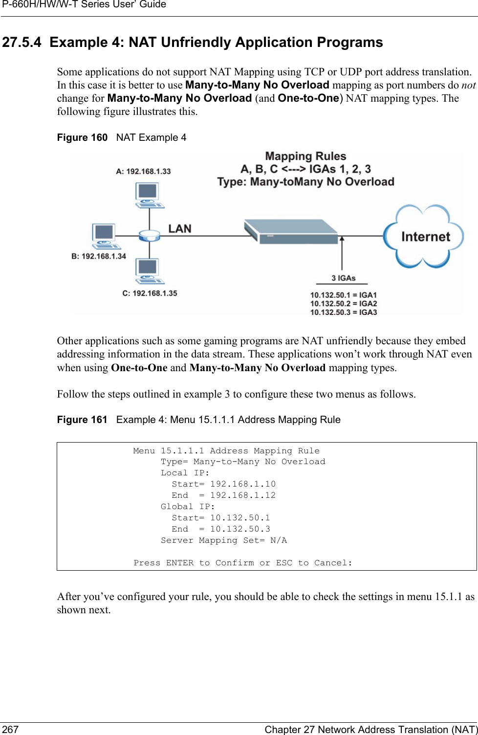
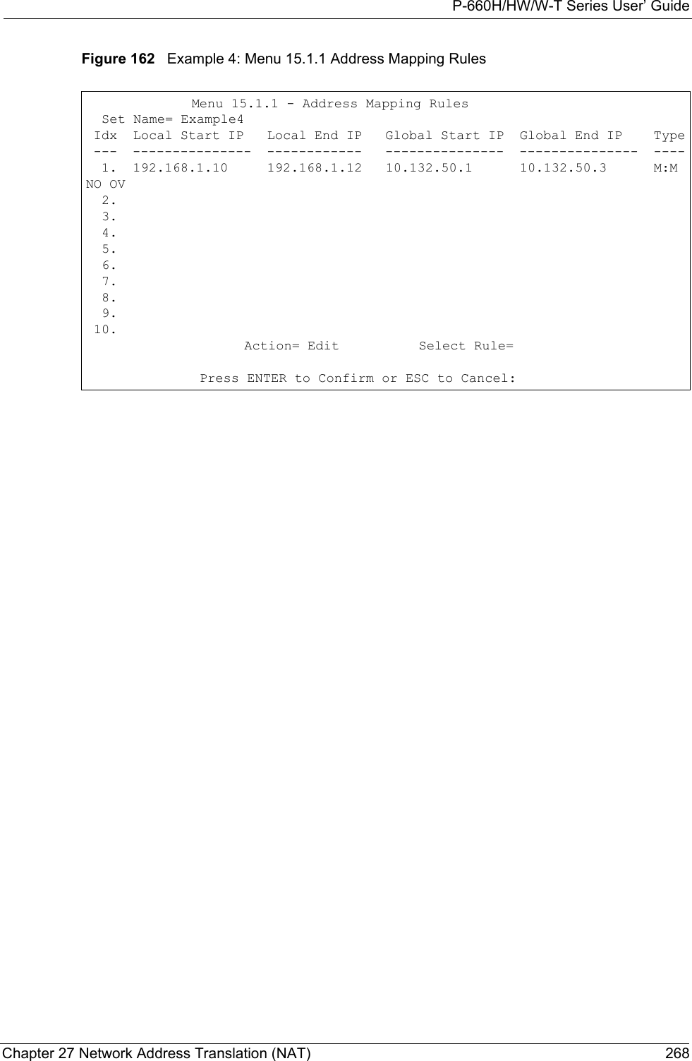
![P-660H/HW/W-T Series User’ GuideChapter 29 Filter Configuration 282Figure 174 Sample Telnet Filter1Enter 1 in the menu 21 to display Menu 21.1 — Filter Set Configuration.2Enter the index number of the filter set you want to configure (in this case 6).3Type a descriptive name or comment in the Edit Comments field (for example, TELNET_WAN) and press [ENTER].4Press [ENTER] at the message “Press [ENTER] to confirm or [ESC] to cancel...” to open Menu 21.1.6 — Filter Rules Summary.5Type 1 to configure the first filter rule. Make the entries in this menu as shown next.When you press [ENTER] to confirm, the following screen appears. Note that there is only one filter rule in this set.Figure 175 Menu 21.1.6.1 Sample Filter After you have created the filter set, you must apply it.1Enter 11 in the main menu to display menu 11 and type the remote node number to edit.Menu 21.1.6.1 - TCP/IP Filter RuleFilter #: 6,1Filter Type= TCP/IP Filter RuleActive= YesIP Protocol= 6 IP Source Route= NoDestination: IP Addr= 0.0.0.0IP Mask= 0.0.0.0Port #= 23Port # Comp= Equal Source: IP Addr= 0.0.0.0IP Mask= 0.0.0.0Port #= Port # Comp= EqualTCP Estab= NoMore= No Log= NoneAction Matched= DropAction Not Matched= ForwardPress ENTER to Confirm or ESC to Cancel:](https://usermanual.wiki/ZyXEL-Communications/P660HWTX.Users-Manual-3/User-Guide-566052-Page-112.png)
![P-660H/HW/W-T Series User’ Guide283 Chapter 29 Filter Configuration2Go to the Edit Filter Sets field, press [SPACE BAR] to choose Ye s and press [ENTER].This brings you to menu 11.5. Apply the example filter set (for example, filter set 3) in this menu as shown in the next section.This shows you that you have configured and activated (A = Y) a TCP/IP filter rule (Type = IP, Pr = 6) for destination telnet ports (DP = 23).M = N means an action can be taken immediately. The action is to drop the packet (m = D) if the action is matched and to forward the packet immediately (n = F) if the action is not matched no matter whether there are more rules to be checked (there aren’t in this example).Figure 176 Menu 21.1.6.1 Sample Filter Rules Summary29.7 Applying Filters and Factory DefaultsThis section shows you where to apply the filter(s) after you design it (them). Sets of factory default filter rules have been configured in menu 21 (but have not been applied) to filter traffic.Menu 21.1.6 - Filter Rules Summary # A Type Filter Rules M m n - - ---- --------------------------------------------------------------- - - - 1 Y IP Pr=6, SA=0.0.0.0, DA=0.0.0.0, DP=23 N D F 2 N 3 N 4 N 5 N 6 NEnter Filter Rule Number (1-6) to Configure: 1Table 98 Filter Sets TableFILTER SETS DESCRIPTIONInput Filter Sets: Apply filters for incoming traffic. You may apply protocol or device filter rules. See earlier in this chapter for information on filters. Output Filter Sets: Apply filters for traffic leaving the Prestige. You may apply filter rules for protocol or device filters. See earlier in this section for information on types of filters.Call Filter Sets: Apply filters to decide if a packet should be allowed to trigger a call.](https://usermanual.wiki/ZyXEL-Communications/P660HWTX.Users-Manual-3/User-Guide-566052-Page-113.png)
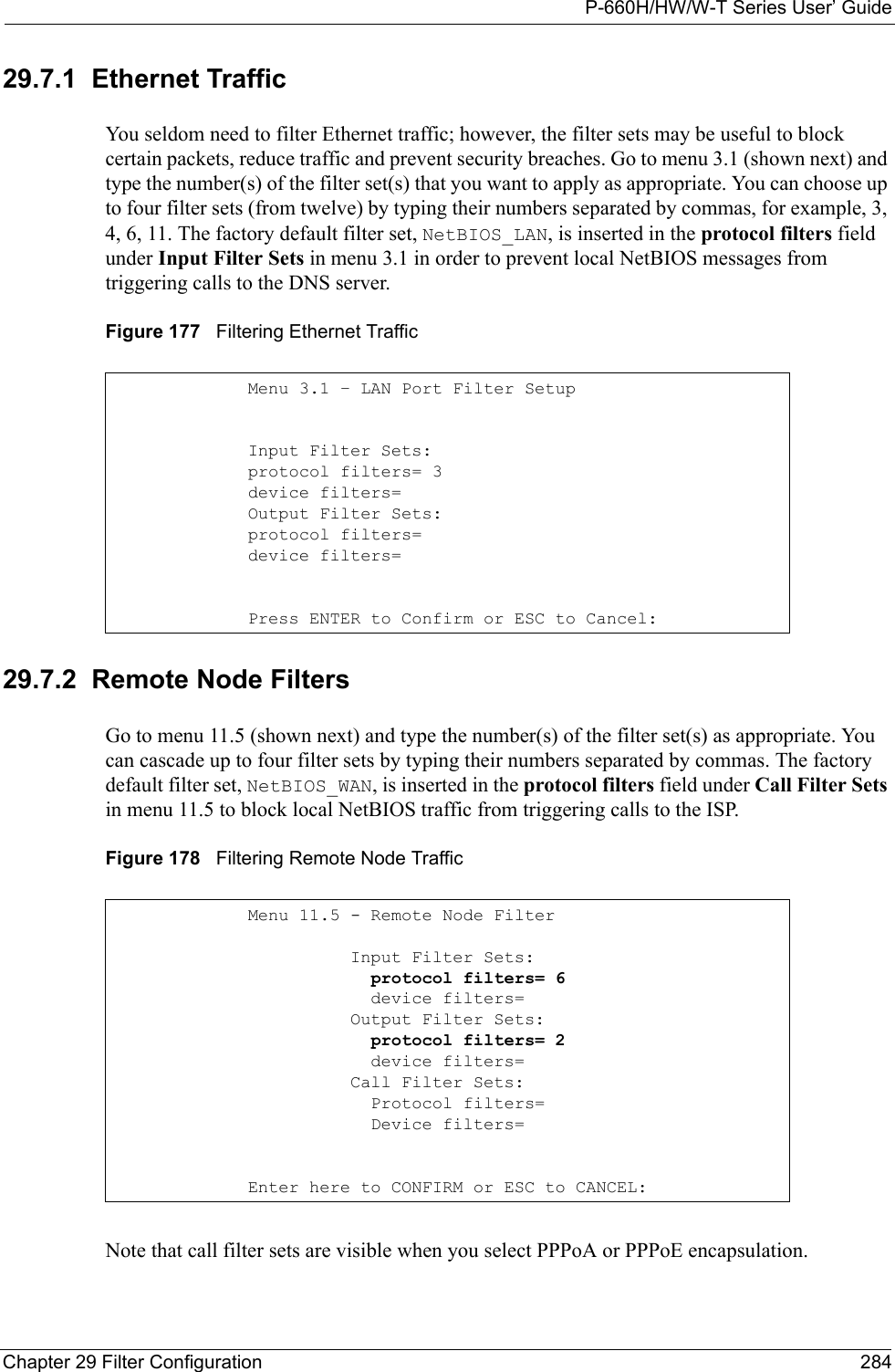

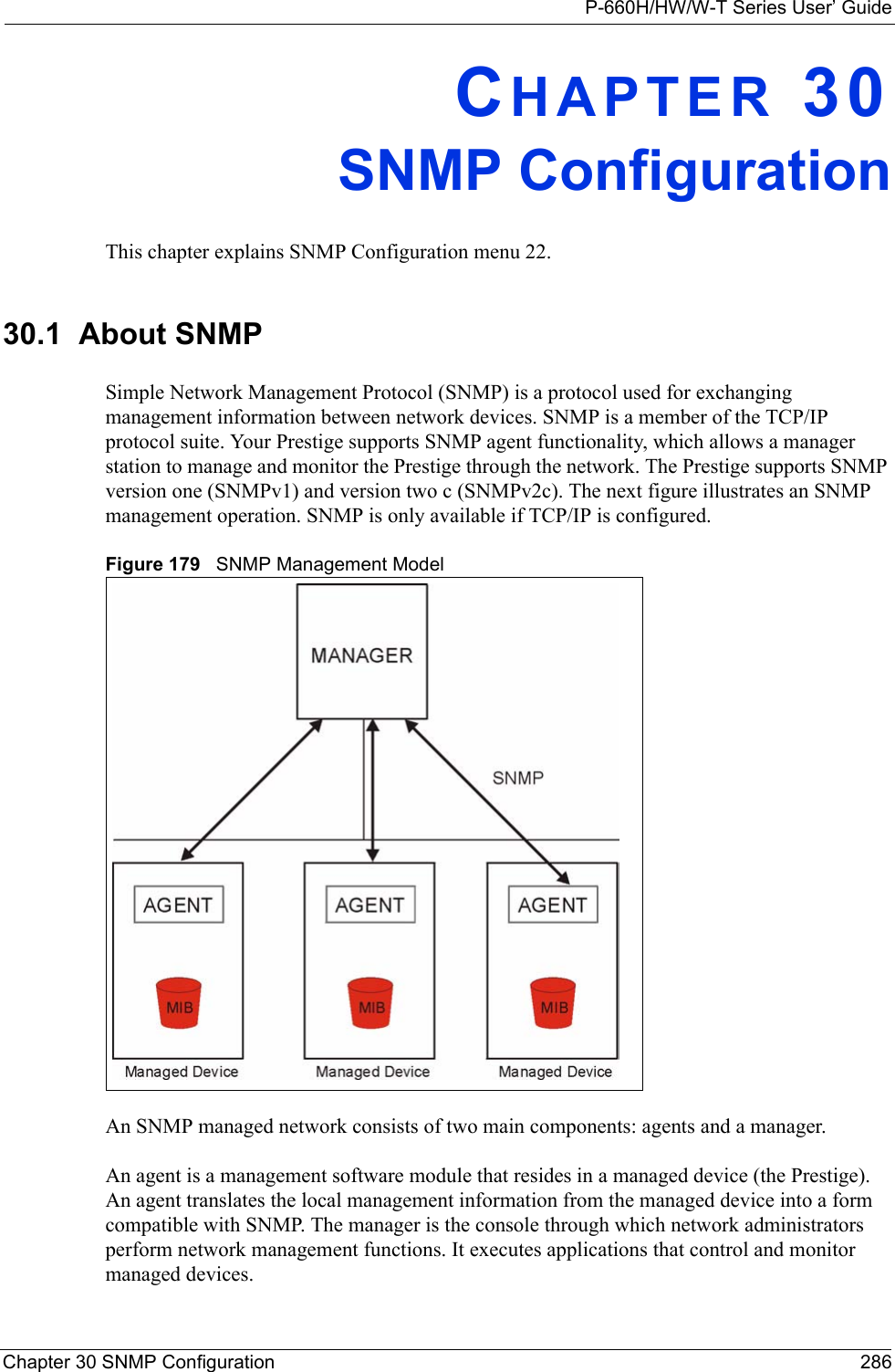
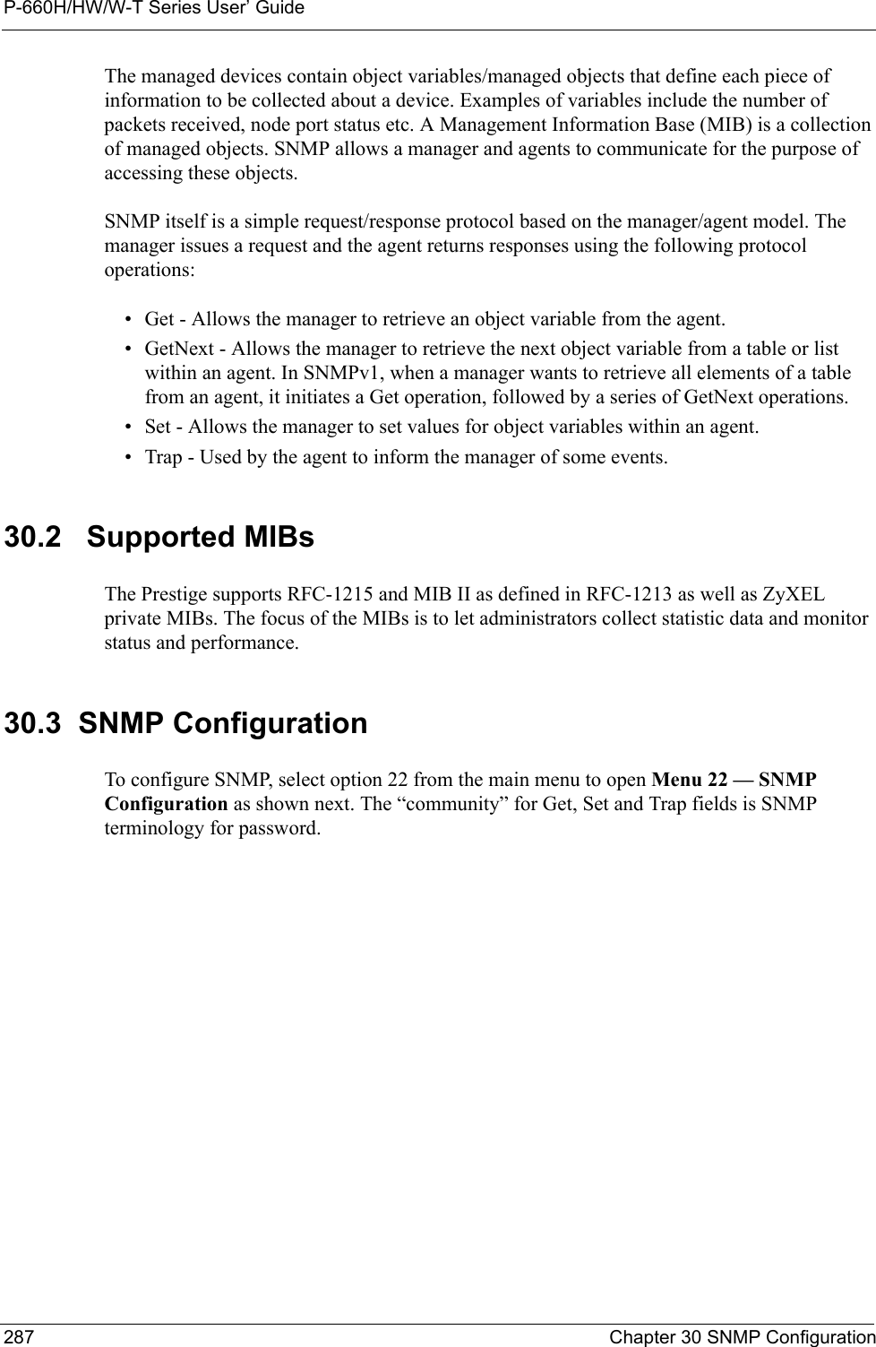
![P-660H/HW/W-T Series User’ GuideChapter 30 SNMP Configuration 288Figure 180 Menu 22 SNMP ConfigurationThe following table describes the SNMP configuration parameters.30.4 SNMP Traps The Prestige will send traps to the SNMP manager when any one of the following events occurs:Menu 22 - SNMP ConfigurationSNMP: Get Community= public Set Community= public Trusted Host= 0.0.0.0 Trap: Community= public Destination= 0.0.0.0Press ENTER to Confirm or ESC to Cancel:Table 99 Menu 22 SNMP ConfigurationFIELD DESCRIPTIONSNMP:Get Community Type the Get Community, which is the password for the incoming Get- and GetNext requests from the management station.Set Community Type the Set community, which is the password for incoming Set requests from the management station. Trusted Host If you enter a trusted host, your Prestige will only respond to SNMP messages from this address. A blank (default) field means your Prestige will respond to all SNMP messages it receives, regardless of source.Trap:Community Type the trap community, which is the password sent with each trap to the SNMP manager. Destination Type the IP address of the station to send your SNMP traps to.When you have completed this menu, press [ENTER] at the prompt “Press ENTER to Confirm or ESC to Cancel:” to save your configuration, or press [ESC] at any time to cancel.Table 100 SNMP TrapsTRAP # TRAP NAME DESCRIPTION1coldStart (defined in RFC-1215)A trap is sent after booting (power on).2warmStart (defined in RFC-1215)A trap is sent after booting (software reboot).3linkDown (defined in RFC-1215)A trap is sent with the port number when any of the links are down. See the following table.4linkUp (defined in RFC-1215)A trap is sent with the port number.](https://usermanual.wiki/ZyXEL-Communications/P660HWTX.Users-Manual-3/User-Guide-566052-Page-118.png)
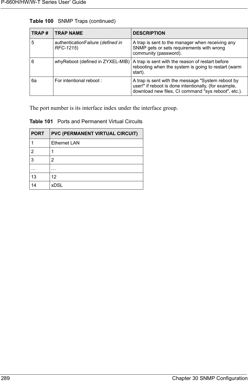
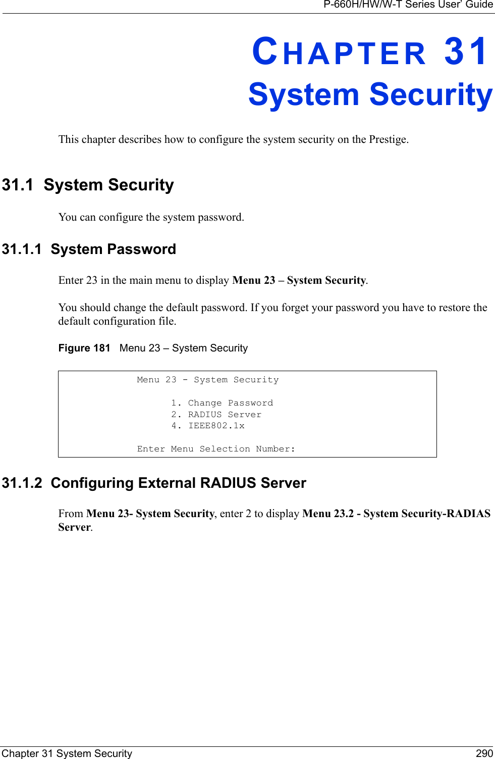
![P-660H/HW/W-T Series User’ Guide291 Chapter 31 System SecurityFigure 182 Menu 23.2 System Security: RADIUS ServerThe following table describes the fields in this menu.Menu 23.2 - System Security - RADIUS Server Authentication Server: Active= No Server Address= 10.11.12.13 Port #= 1812 Shared Secret= ******** Accounting Server: Active= No Server Address= 10.11.12.13 Port #= 1813 Shared Secret= ********Press ENTER to Confirm or ESC to Cancel:Table 102 Menu 23.2 System Security: RADIUS ServerFIELD DESCRIPTIONAuthentication ServerActive Press [SPACE BAR] to select Yes and press [ENTER] to enable user authentication through an external authentication server. Server Address Enter the IP address of the external authentication server in dotted decimal notation. Port The default port of the RADIUS server for authentication is 1812. You need not change this value unless your network administrator instructs you to do so with additional information. Shared Secret Specify a password (up to 31 alphanumeric characters) as the key to be shared between the external authentication server and the access points. The key is not sent over the network. This key must be the same on the external authentication server and Prestige. Accounting ServerActive Press [SPACE BAR] to select Yes and press [ENTER] to enable user authentication through an external accounting server. Server Address Enter the IP address of the external accounting server in dotted decimal notation. Port The default port of the RADIUS server for accounting is 1813. You need not change this value unless your network administrator instructs you to do so with additional information. Shared Secret Specify a password (up to 31 alphanumeric characters) as the key to be shared between the external accounting server and the access points. The key is not sent over the network. This key must be the same on the external accounting server and Prestige.When you have completed this menu, press [ENTER] at the prompt “Press ENTER to Confirm or ESC to Cancel:” to save your configuration, or press [ESC] at any time to cancel.](https://usermanual.wiki/ZyXEL-Communications/P660HWTX.Users-Manual-3/User-Guide-566052-Page-121.png)
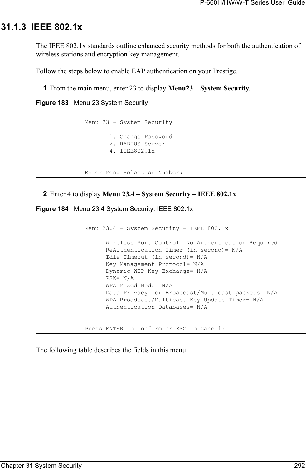
![P-660H/HW/W-T Series User’ Guide293 Chapter 31 System SecurityTable 103 Menu 23.4 System Security: IEEE 802.1xFIELD DESCRIPTIONWireless Port ControlPress [SPACE BAR] and select a security mode for the wireless LAN access. Select No Authentication Required to allow any wireless stations access to your wired network without entering usernames and passwords. This is the default setting.Selecting Authentication Required means wireless stations have to enter usernames and passwords before access to the wired network is allowed. Select No Access Allowed to block all wireless stations access to the wired network. The following fields are not available when you select No Authentication Required or No Access Allowed.ReAuthentica-tion Timer(in second)Specify how often a client has to re-enter username and password to stay connected to the wired network. This field is activated only when you select Authentication Required in the Wireless Port Control field. Enter a time interval between 10 and 9999 (in seconds). The default time interval is 1800 seconds (or 30 minutes). Idle Timeout (in second)The Prestige automatically disconnects a client from the wired network after a period of inactivity. The client needs to enter the username and password again before access to the wired network is allowed. This field is activated only when you select Authentication Required in the Wireless Port Control field. The default time interval is 3600 seconds (or 1 hour).Key Management ProtocolPress [SPACE BAR] to select 802.1x, WPA or WPA-PSK and press [ENTER].Dynamic WEP Key ExchangeThis field is activated only when you select Authentication Required in the Wireless Port Control field. Also set the Authentication Databases field to RADIUS Only. Local user database may not be used. Select Disable to allow wireless stations to communicate with the access points without using Dynamic WEP Key Exchange. Select 64-bit WEP or 128-bit WEP to enable data encryption. Up to 32 stations can access the Prestige when you configure Dynamic WEP Key Exchange. This field is not available when you set Key Management Protocol to WPA or WPA-PSK.PSK Type a pre-shared key from 8 to 63 case-sensitive ASCII characters (including spaces and symbols) when you select WPA-PSK in the Key Management Protocol field. WPA Mixed ModeSelect Enable to activate WPA mixed mode. Otherwise, select Disable and configure Group Data Privacy field.Data Privacy for Broadcast/ Multicast packetsThis field allows you to choose TKIP (recommended) or WEP for broadcast and multicast (“group”) traffic if the Key Management Protocol is WPA and WPA Mixed Mode is disabled. WEP is used automatically if you have enabled WPA Mixed Mode. All unicast traffic is automatically encrypted by TKIP when WPA or WPA-PSK Key Management Protocol is selected.WPA Broadcast/ Multicast Key Update TimerThe WPA Broadcast/Multicast Key Update Timer is the rate at which the AP (if using WPA-PSK key management) or RADIUS server (if using WPA key management) sends a new group key out to all clients. The re-keying process is the WPA equivalent of automatically changing the WEP key for an AP and all stations in a WLAN on a periodic basis. Setting of the WPA Broadcast/Multicast Key Update Timer is also supported in WPA-PSK mode. The Prestige default is 1800 seconds (30 minutes).](https://usermanual.wiki/ZyXEL-Communications/P660HWTX.Users-Manual-3/User-Guide-566052-Page-123.png)
![P-660H/HW/W-T Series User’ GuideChapter 31 System Security 294Once you enable user authentication, you need to specify an external RADIUS server or create local user accounts on the Prestige for authentication. 31.2 Creating User Accounts on the Prestige By storing user profiles locally, your Prestige is able to authenticate wireless users without interacting with a network RADIUS server. Follow the steps below to set up user profiles on your Prestige.1From the main menu, enter 14 to display Menu 14 - Dial-in User Setup.Authentication DatabasesThe authentication database contains wireless station login information. The local user database is the built-in database on the Prestige. The RADIUS is an external server. Use this field to decide which database the Prestige should use (first) to authenticate a wireless station.Before you specify the priority, make sure you have set up the corresponding database correctly first. When you configure Key Management Protocol to WPA, the Authentication Databases must be RADIUS Only. You can only use the Local User Database with 802.1x Key Management Protocol.Select Local User Database Only to have the Prestige just check the built-in user database on the Prestige for a wireless station's username and password. Select RADIUS Only to have the Prestige just check the user database on the specified RADIUS server for a wireless station's username and password. Select Local first, then RADIUS to have the Prestige first check the user database on the Prestige for a wireless station's username and password. If the user name is not found, the Prestige then checks the user database on the specified RADIUS server.Select RADIUS first, then Local to have the Prestige first check the user database on the specified RADIUS server for a wireless station's username and password. If the Prestige cannot reach the RADIUS server, the Prestige then checks the local user database on the Prestige. When the user name is not found or password does not match in the RADIUS server, the Prestige will not check the local user database and the authentication fails.When you have completed this menu, press [ENTER] at the prompt “Press ENTER to Confirm or ESC to Cancel:” to save your configuration, or press [ESC] at any time to cancel.Table 103 Menu 23.4 System Security: IEEE 802.1x (continued)FIELD DESCRIPTION](https://usermanual.wiki/ZyXEL-Communications/P660HWTX.Users-Manual-3/User-Guide-566052-Page-124.png)
![P-660H/HW/W-T Series User’ Guide295 Chapter 31 System SecurityFigure 185 Menu 14 Dial-in User Setup2Type a number and press [ENTER] to edit the user profile. Figure 186 Menu 14.1 Edit Dial-in UserThe following table describes the fields in this menu. Menu 14 - Dial-in User Setup 1. ________ 9. ________ 17. ________ 25. ________ 2. ________ 10. ________ 18. ________ 26. ________ 3. ________ 11. ________ 19. ________ 27. ________ 4. ________ 12. ________ 20. ________ 28. ________ 5. ________ 13. ________ 21. ________ 29. ________ 6. ________ 14. ________ 22. ________ 30. ________ 7. ________ 15. ________ 23. ________ 31. ________ 8. ________ 16. ________ 24. ________ 32. ________ Enter Menu Selection Number:Menu 14.1 - Edit Dial-in User User Name= test Active= Yes Password= ********Press ENTER to Confirm or ESC to Cancel:Table 104 Menu 14.1 Edit Dial-in UserFIELD DESCRIPTIONUser Name Enter a username up to 31 alphanumeric characters long for this user profile.This field is case sensitive.Active Press [SPACE BAR] to select Yes and press [ENTER] to enable the user profile. Password Enter a password up to 31 characters long for this user profile. When you have completed this menu, press [ENTER] at the prompt “Press ENTER to Confirm or ESC to Cancel:” to save your configuration, or press [ESC] at any time to cancel.](https://usermanual.wiki/ZyXEL-Communications/P660HWTX.Users-Manual-3/User-Guide-566052-Page-125.png)
![P-660H/HW/W-T Series User’ GuideChapter 32 System Information and Diagnosis 296CHAPTER 32System Information andDiagnosisThis chapter covers the information and diagnostic tools in SMT menus 24.1 to 24.4.32.1 OverviewThese tools include updates on system status, port status, log and trace capabilities and upgrades for the system software. This chapter describes how to use these tools in detail.Type 24 in the main menu to open Menu 24 – System Maintenance, as shown in the following figure.Figure 187 Menu 24 System Maintenance32.2 System StatusThe first selection, System Status gives you information on the status and statistics of the ports, as shown next. System Status is a tool that can be used to monitor your Prestige. Specifically, it gives you information on your DSL telephone line status, number of packets sent and received.To get to System Status, type 24 to go to Menu 24 — System Maintenance. From this menu, type 1. System Status. There are two commands in Menu 24.1 — System Maintenance — Status. Entering 1 resets the counters; [ESC] takes you back to the previous screen.Menu 24 - System Maintenance1. System Status2. System Information and Console Port Speed3. Log and Trace4. Diagnostic5. Backup Configuration6. Restore Configuration7. Upload Firmware8. Command Interpreter Mode9. Call Control10. Time and Date Setting11. Remote Management Enter Menu Selection Number:](https://usermanual.wiki/ZyXEL-Communications/P660HWTX.Users-Manual-3/User-Guide-566052-Page-126.png)
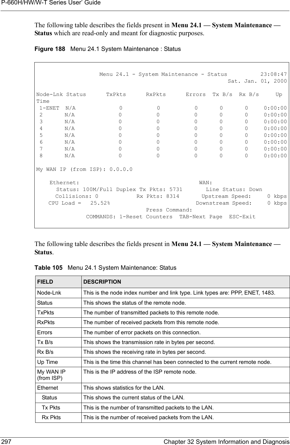
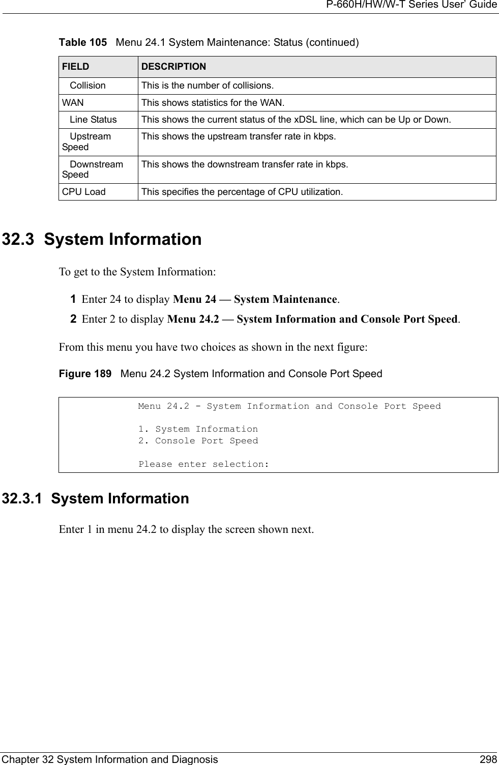
![P-660H/HW/W-T Series User’ Guide299 Chapter 32 System Information and DiagnosisFigure 190 Menu 24.2.1 System Maintenance: InformationThe following table describes the fields in this menu.32.3.2 Console Port SpeedNote: The console port is internal and reserved for technician use only.You can set up different port speeds for the console port through Menu 24.2.2 – System Maintenance – Console Port Speed. Your Prestige supports 9600 (default), 19200, 38400, 57600 and 115200 bps. Press [SPACE BAR] and then [ENTER] to select the desired speed in menu 24.2.2, as shown in the following figure. Menu 24.2.1 - System Maintenance - Information Name: Routing: IP ZyNOS F/W Version: V3.40(ACC.0)| 04/26/2005 ADSL Chipset Vendor: DMT FwVer: 3.0.11.11_A_TC, HwVer: T14F+ Standard: Multi-Mode LAN Ethernet Address: 00:13:49:11:11:35 IP Address: 192.168.1.1 IP Mask: 255.255.255.0 DHCP: Server Press ESC or RETURN to Exit:Table 106 Menu 24.2.1 System Maintenance: InformationFIELD DESCRIPTIONName Displays the system name of your Prestige. This information can be changed in Menu 1 – General Setup.Routing Refers to the routing protocol used.ZyNOS F/W Version Refers to the ZyNOS (ZyXEL Network Operating System) system firmware version. ZyNOS is a registered trademark of ZyXEL Communications Corporation.ADSL Chipset VendorDisplays the vendor of the ADSL chipset and DSL version.Standard This refers to the operational protocol the Prestige and the DSLAM (Digital Subscriber Line Access Multiplexer) are using.LANEthernet Address Refers to the Ethernet MAC (Media Access Control) of your Prestige.IP Address This is the IP address of the Prestige in dotted decimal notation.IP Mask This shows the subnet mask of the Prestige.DHCP This field shows the DHCP setting (None, Relay or Server) of the Prestige.](https://usermanual.wiki/ZyXEL-Communications/P660HWTX.Users-Manual-3/User-Guide-566052-Page-129.png)