ZyXEL Communications VMG8324B10A Wireless N VDSL2 VoIP Combo WAN Gigabit IAD User Manual VMG8324 B10A UserMan 1 2013 12 09
ZyXEL Communications Corporation Wireless N VDSL2 VoIP Combo WAN Gigabit IAD VMG8324 B10A UserMan 1 2013 12 09
Contents
- 1. (VMG8324-B10A)UserMan(1) 2013-12-09
- 2. (VMG8324-B10A)UserMan(2) 2013-12-09
(VMG8324-B10A)UserMan(1) 2013-12-09

Quick Start Guide
www.zyxel.com
VMG8 3 2 4 - B1 0 A and VMG8 3 2 4 -
B3 0 A Series
Wireless N VDSL2 VoI P Com bo WAN Gigabit I AD
Version 1.00
Edit ion 1, 11/ 2013
Copyright © 2013 ZyXEL Com m unications Corporation
User’s Guide
Defa ult Login Det a ils
LAN I P Address ht tp: / / 192.168.1.1
Login adm in
Password 1234

VMG8324-B10A / VMG8324-B30A Series User’s Guide2
IMPORTANT!
READ CAREFULLY BEFORE USE.
KEEP THIS GUIDE FOR FUTURE REFERENCE.
Screenshots and graphics in t his book m ay differ slightly from your product due t o differences in
your product firm war e or your com put er operat ing syst em . Every effort has been m ade t o ensure
that t he inform at ion in t his m anual is accurat e.
Related Documentation
• Quick Start Guide
The Quick St art Guide show s how to connect t he Device and get up and running right away.

Contents Overview
VMG8324-B10A / VMG8324-B30A Series User’s Guide 3
Contents Overview
User’s Guide .......................................................................................................................................15
Introducing the Device ............................................................................................................................17
The Web Configurator .............................................................................................................................25
Quick Start ...............................................................................................................................................33
Technical Reference ..........................................................................................................................35
Network Map and Status Screens ...........................................................................................................37
Broadband ...............................................................................................................................................43
Wireless ..................................................................................................................................................71
Home Networking ..................................................................................................................................107
Routing ..................................................................................................................................................131
Quality of Service (QoS) .......................................................................................................................139
Network Address Translation (NAT) ......................................................................................................157
Dynamic DNS Setup .............................................................................................................................175
Interface Group .....................................................................................................................................179
USB Service ..........................................................................................................................................185
Power Management ..............................................................................................................................193
Firewall ..................................................................................................................................................197
MAC Filter .............................................................................................................................................205
Parental Control ....................................................................................................................................207
Scheduler Rule ...................................................................................................................................... 211
Certificates ............................................................................................................................................213
VPN .......................................................................................................................................................221
Voice .....................................................................................................................................................235
Log .......................................................................................................................................................267
Traffic Status ........................................................................................................................................271
VoIP Status ...........................................................................................................................................275
ARP Table .............................................................................................................................................277
Routing Table ........................................................................................................................................279
IGMP/MLD Status ................................................................................................................................281
xDSL Statistics ......................................................................................................................................283
3G Statistics .........................................................................................................................................287
User Account .........................................................................................................................................289
Remote Management ............................................................................................................................291
TR-069 Client ........................................................................................................................................295
TR-064 ..................................................................................................................................................297
SNMP ....................................................................................................................................................299
Time Settings ........................................................................................................................................301

Contents Overview
VMG8324-B10A / VMG8324-B30A Series User’s Guide
4
E-mail Notification .................................................................................................................................305
Logs Setting .........................................................................................................................................307
Firmware Upgrade ................................................................................................................................ 311
Configuration .........................................................................................................................................313
Diagnostic .............................................................................................................................................317
Troubleshooting ....................................................................................................................................323

Table of Contents
VMG8324-B10A / VMG8324-B30A Series User’s Guide 5
Table of Contents
Contents Overview ..............................................................................................................................3
Table of Contents .................................................................................................................................5
Part I: User’s Guide ......................................................................................... 15
Chapter 1
Introducing the Device .......................................................................................................................17
1.1 Overview ...........................................................................................................................................17
1.2 Ways to Manage the Device .............................................................................................................17
1.3 Good Habits for Managing the Device ..............................................................................................17
1.4 Applications for the Device ...............................................................................................................18
1.4.1 Internet Access ........................................................................................................................18
1.4.2 Device’s USB Support .............................................................................................................19
1.5 LEDs (Lights) ....................................................................................................................................20
1.6 The RESET Button ............................................................................................................................22
1.7 Wireless Access ................................................................................................................................22
1.7.1 Using the Wi-Fi and WPS Buttons ...........................................................................................22
1.8 Wall-mounting Instructions ................................................................................................................23
Chapter 2
The Web Configurator ........................................................................................................................25
2.1 Overview ...........................................................................................................................................25
2.1.1 Accessing the Web Configurator .............................................................................................25
2.2 Web Configurator Layout ..................................................................................................................27
2.2.1 Title Bar ...................................................................................................................................27
2.2.2 Main Window ...........................................................................................................................28
2.2.3 Navigation Panel .....................................................................................................................29
Chapter 3
Quick Start...........................................................................................................................................33
3.1 Overview ...........................................................................................................................................33
3.2 Quick Start Setup ..............................................................................................................................33
Part II: Technical Reference............................................................................ 35

Table of Contents
VMG8324-B10A / VMG8324-B30A Series User’s Guide
6
Chapter 4
Network Map and Status Screens ..................................................................................................... 37
4.1 Overview ...........................................................................................................................................37
4.2 The Network Map Screen .................................................................................................................37
4.3 The Status Screen .............................................................................................................................38
Chapter 5
Broadband...........................................................................................................................................43
5.1 Overview ...........................................................................................................................................43
5.1.1 What You Can Do in this Chapter ............................................................................................43
5.1.2 What You Need to Know ..........................................................................................................44
5.1.3 Before You Begin .....................................................................................................................47
5.2 The Broadband Screen .....................................................................................................................47
5.2.1 Add/Edit Internet Connection ...................................................................................................49
5.3 The 3G Backup Screen .....................................................................................................................57
5.4 The Advanced Screen .......................................................................................................................61
5.5 The 802.1x Screen ............................................................................................................................62
5.5.1 Edit 802.1X Settings ................................................................................................................63
5.6 The WAN Status Screen ...................................................................................................................63
5.7 Technical Reference ..........................................................................................................................64
Chapter 6
Wireless ...............................................................................................................................................71
6.1 Overview ...........................................................................................................................................71
6.1.1 What You Can Do in this Chapter ............................................................................................71
6.1.2 What You Need to Know ..........................................................................................................72
6.2 The General Screen .........................................................................................................................72
6.2.1 No Security ..............................................................................................................................75
6.2.2 Basic (WEP Encryption) ..........................................................................................................75
6.2.3 Basic (802.1X) .........................................................................................................................76
6.2.4 More Secure (WPA(2)-PSK) ....................................................................................................79
6.2.5 WPA(2) Authentication .............................................................................................................80
6.3 The More AP Screen .........................................................................................................................81
6.3.1 Edit More AP ..........................................................................................................................83
6.4 MAC Authentication ..........................................................................................................................85
6.5 The WPS Screen ..............................................................................................................................86
6.6 The WMM Screen .............................................................................................................................87
6.7 The WDS Screen ..............................................................................................................................88
6.7.1 WDS Scan ...............................................................................................................................89
6.8 The Others Screen ............................................................................................................................90
6.9 The Channel Status Screen ..............................................................................................................92
6.10 Technical Reference ........................................................................................................................92
6.10.1 Wireless Network Overview ...................................................................................................92

Table of Contents
VMG8324-B10A / VMG8324-B30A Series User’s Guide 7
6.10.2 Additional Wireless Terms .....................................................................................................94
6.10.3 Wireless Security Overview ...................................................................................................94
6.10.4 Signal Problems ....................................................................................................................96
6.10.5 BSS .......................................................................................................................................97
6.10.6 MBSSID .................................................................................................................................97
6.10.7 Preamble Type ......................................................................................................................98
6.10.8 Wireless Distribution System (WDS) .....................................................................................98
6.10.9 WiFi Protected Setup (WPS) .................................................................................................98
Chapter 7
Home Networking .............................................................................................................................107
7.1 Overview .........................................................................................................................................107
7.1.1 What You Can Do in this Chapter ..........................................................................................107
7.1.2 What You Need To Know .......................................................................................................108
7.1.3 Before You Begin ...................................................................................................................109
7.2 The LAN Setup Screen ...................................................................................................................109
7.3 The Static DHCP Screen ................................................................................................................. 113
7.4 The UPnP Screen ........................................................................................................................... 114
7.5 Installing UPnP in Windows Example ............................................................................................. 115
7.6 Using UPnP in Windows XP Example ............................................................................................ 118
7.7 The Additional Subnet Screen ........................................................................................................124
7.8 The STB Vendor ID Screen .............................................................................................................125
7.9 The 5th Ethernet Port Screen .........................................................................................................125
7.10 The LAN VLAN Screen .................................................................................................................126
7.11 The Wake on LAN Screen .............................................................................................................127
7.12 Technical Reference ......................................................................................................................128
7.12.1 LANs, WANs and the Device ...............................................................................................128
7.12.2 DHCP Setup ........................................................................................................................128
7.12.3 DNS Server Addresses .......................................................................................................128
7.12.4 LAN TCP/IP .........................................................................................................................129
Chapter 8
Routing ..............................................................................................................................................131
8.1 Overview ........................................................................................................................................131
8.2 The Routing Screen ........................................................................................................................132
8.2.1 Add/Edit Static Route .............................................................................................................133
8.3 The DNS Route Screen ..................................................................................................................134
8.3.1 The DNS Route Add Screen .................................................................................................134
8.4 The Policy Forwarding Screen ........................................................................................................135
8.4.1 Add/Edit Policy Forwarding ...................................................................................................136
8.5 RIP ..............................................................................................................................................137
8.5.1 The RIP Screen .....................................................................................................................137

Table of Contents
VMG8324-B10A / VMG8324-B30A Series User’s Guide
8
Chapter 9
Quality of Service (QoS)...................................................................................................................139
9.1 Overview ........................................................................................................................................139
9.1.1 What You Can Do in this Chapter ..........................................................................................139
9.2 What You Need to Know .................................................................................................................139
9.3 The Quality of Service General Screen ..........................................................................................141
9.4 The Queue Setup Screen ...............................................................................................................142
9.4.1 Adding a QoS Queue ...........................................................................................................143
9.5 The Class Setup Screen .................................................................................................................144
9.5.1 Add/Edit QoS Class ..............................................................................................................146
9.6 The QoS Policer Setup Screen .......................................................................................................149
9.6.1 Add/Edit a QoS Policer .........................................................................................................150
9.7 The QoS Monitor Screen ...............................................................................................................151
9.8 Technical Reference ........................................................................................................................152
Chapter 10
Network Address Translation (NAT)................................................................................................157
10.1 Overview .......................................................................................................................................157
10.1.1 What You Can Do in this Chapter ........................................................................................157
10.1.2 What You Need To Know .....................................................................................................157
10.2 The Port Forwarding Screen ........................................................................................................158
10.2.1 Add/Edit Port Forwarding ...................................................................................................160
10.3 The Applications Screen ...............................................................................................................161
10.3.1 Add New Application ...........................................................................................................162
10.4 The Port Triggering Screen ...........................................................................................................162
10.4.1 Add/Edit Port Triggering Rule .............................................................................................164
10.5 The DMZ Screen ...........................................................................................................................165
10.6 The ALG Screen ...........................................................................................................................166
10.7 The Address Mapping Screen .......................................................................................................166
10.7.1 Add/Edit Address Mapping Rule ..........................................................................................167
10.8 The Address Mapping Screen .......................................................................................................168
10.9 The Sessions Screen ....................................................................................................................169
10.10 Technical Reference ....................................................................................................................169
10.10.1 NAT Definitions ..................................................................................................................170
10.10.2 What NAT Does .................................................................................................................171
10.10.3 How NAT Works ................................................................................................................172
10.10.4 NAT Application .................................................................................................................173
Chapter 11
Dynamic DNS Setup .........................................................................................................................175
11.1 Overview .......................................................................................................................................175
11.1.1 What You Can Do in this Chapter ........................................................................................175
11.1.2 What You Need To Know .....................................................................................................176

Table of Contents
VMG8324-B10A / VMG8324-B30A Series User’s Guide 9
11.2 The DNS Entry Screen ..................................................................................................................176
11.2.1 Add/Edit DNS Entry .............................................................................................................177
11.3 The Dynamic DNS Screen ............................................................................................................177
Chapter 12
Interface Group .................................................................................................................................179
12.1 Overview .......................................................................................................................................179
12.1.1 What You Can Do in this Chapter ........................................................................................179
12.2 The Interface Group Screen ..........................................................................................................179
12.2.1 Interface Group Configuration .............................................................................................180
12.2.2 Interface Grouping Criteria .................................................................................................182
Chapter 13
USB Service ......................................................................................................................................185
13.1 Overview .......................................................................................................................................185
13.1.1 What You Can Do in this Chapter ........................................................................................185
13.1.2 What You Need To Know .....................................................................................................185
13.1.3 Before You Begin .................................................................................................................187
13.2 The File Sharing Screen ...............................................................................................................188
13.2.1 The Add New Share Screen ................................................................................................189
13.2.2 The Add New User Screen ..................................................................................................190
13.3 The Media Server Screen .............................................................................................................190
13.4 Printer Server ...............................................................................................................................191
13.4.1 Before You Begin .................................................................................................................191
13.4.2 The Printer Server Screen ...................................................................................................192
Chapter 14
Power Management ..........................................................................................................................193
14.1 Overview .......................................................................................................................................193
14.1.1 What You Can Do in this Chapter ........................................................................................193
14.1.2 What You Need To Know .....................................................................................................193
14.2 The Power Management Screen ..................................................................................................193
14.3 The Auto Switch Off Screen ..........................................................................................................194
14.3.1 The Auto Switch Off Add/Edit Screen ..................................................................................195
14.3.2 The Add/Edit Rule Screen ...................................................................................................195
Chapter 15
Firewall ..............................................................................................................................................197
15.1 Overview .......................................................................................................................................197
15.1.1 What You Can Do in this Chapter ........................................................................................197
15.1.2 What You Need to Know ......................................................................................................198
15.2 The Firewall Screen ......................................................................................................................199
15.3 The Protocol Screen ....................................................................................................................199

Table of Contents
VMG8324-B10A / VMG8324-B30A Series User’s Guide
10
15.3.1 Add/Edit a Service ..............................................................................................................200
15.4 The Access Control Screen ..........................................................................................................201
15.4.1 Add/Edit an ACL Rule ........................................................................................................202
15.5 The DoS Screen ............................................................................................................................204
Chapter 16
MAC Filter..........................................................................................................................................205
16.1 Overview ......................................................................................................................................205
16.2 The MAC Filter Screen ..................................................................................................................205
Chapter 17
Parental Control................................................................................................................................207
17.1 Overview .......................................................................................................................................207
17.2 The Parental Control Screen .........................................................................................................207
17.2.1 Add/Edit a Parental Control Rule .........................................................................................208
Chapter 18
Scheduler Rule.................................................................................................................................. 211
18.1 Overview ....................................................................................................................................... 211
18.2 The Scheduler Rule Screen .......................................................................................................... 211
18.2.1 Add/Edit a Schedule ............................................................................................................212
Chapter 19
Certificates ........................................................................................................................................213
19.1 Overview .......................................................................................................................................213
19.1.1 What You Can Do in this Chapter ........................................................................................213
19.2 What You Need to Know ...............................................................................................................213
19.3 The Local Certificates Screen .......................................................................................................213
19.3.1 Create Certificate Request .................................................................................................214
19.3.2 Load Signed Certificate ......................................................................................................215
19.4 The Trusted CA Screen ................................................................................................................216
19.4.1 View Trusted CA Certificate .................................................................................................218
19.4.2 Import Trusted CA Certificate ..............................................................................................219
Chapter 20
VPN ....................................................................................................................................................221
20.1 Overview .......................................................................................................................................221
20.2 The IPSec VPN General Screen ...................................................................................................221
20.3 The IPSec VPN Add/Edit Screen ..................................................................................................222
20.4 The IPSec VPN Monitor Screen ....................................................................................................228
20.5 Technical Reference ......................................................................................................................228
20.5.1 IPSec Architecture ...............................................................................................................228
20.5.2 Encapsulation ......................................................................................................................229

Table of Contents
VMG8324-B10A / VMG8324-B30A Series User’s Guide 11
20.5.3 IKE Phases .........................................................................................................................230
20.5.4 Negotiation Mode ................................................................................................................231
20.5.5 IPSec and NAT ....................................................................................................................232
20.5.6 VPN, NAT, and NAT Traversal .............................................................................................232
20.5.7 ID Type and Content ............................................................................................................233
20.5.8 Pre-Shared Key ...................................................................................................................234
20.5.9 Diffie-Hellman (DH) Key Groups ..........................................................................................234
Chapter 21
Voice ..................................................................................................................................................235
21.1 Overview .......................................................................................................................................235
21.1.1 What You Can Do in this Chapter ........................................................................................235
21.1.2 What You Need to Know About VoIP ...................................................................................236
21.2 Before You Begin ..........................................................................................................................236
21.3 The SIP Account Screen ..............................................................................................................236
21.3.1 The SIP Account Add/Edit Screen ......................................................................................237
21.4 The SIP Service Provider Screen ................................................................................................241
21.4.1 The SIP Service Provider Add/Edit Screen ........................................................................242
21.4.2 Dial Plan Rules ....................................................................................................................248
21.5 The Phone Screen .......................................................................................................................249
21.6 The Call Rule Screen ....................................................................................................................249
21.7 The Call History Summary Screen ................................................................................................250
21.8 The Call History Outgoing Calls Screen ........................................................................................251
21.9 The Call History Incoming Calls Screen ........................................................................................251
21.10 Technical Reference ....................................................................................................................252
21.10.1 Quality of Service (QoS) ....................................................................................................260
21.10.2 Phone Services Overview .................................................................................................260
Chapter 22
Log ....................................................................................................................................................267
22.1 Overview .......................................................................................................................................267
22.1.1 What You Can Do in this Chapter ........................................................................................267
22.1.2 What You Need To Know .....................................................................................................267
22.2 The System Log Screen ................................................................................................................268
22.3 The Security Log Screen ...............................................................................................................269
Chapter 23
Traffic Status ....................................................................................................................................271
23.1 Overview .......................................................................................................................................271
23.1.1 What You Can Do in this Chapter ........................................................................................271
23.2 The WAN Status Screen ...............................................................................................................271
23.3 The LAN Status Screen .................................................................................................................273
23.4 The NAT Status Screen .................................................................................................................274

Table of Contents
VMG8324-B10A / VMG8324-B30A Series User’s Guide
12
Chapter 24
VoIP Status .......................................................................................................................................275
24.1 The VoIP Status Screen ................................................................................................................275
Chapter 25
ARP Table ..........................................................................................................................................277
25.1 Overview .......................................................................................................................................277
25.1.1 How ARP Works ..................................................................................................................277
25.2 ARP Table Screen .........................................................................................................................277
Chapter 26
Routing Table ....................................................................................................................................279
26.1 Overview .......................................................................................................................................279
26.2 The Routing Table Screen .............................................................................................................279
Chapter 27
IGMP/MLD Status .............................................................................................................................281
27.1 Overview .......................................................................................................................................281
27.2 The IGMP/MLD Group Status Screen ...........................................................................................281
Chapter 28
xDSL Statistics..................................................................................................................................283
28.1 The xDSL Statistics Screen ...........................................................................................................283
Chapter 29
3G Statistics .....................................................................................................................................287
29.1 Overview .......................................................................................................................................287
29.2 The 3G Statistics Screen ...............................................................................................................287
Chapter 30
User Account ....................................................................................................................................289
30.1 Overview ......................................................................................................................................289
30.2 The User Account Screen .............................................................................................................289
Chapter 31
Remote Management........................................................................................................................291
31.1 Overview .......................................................................................................................................291
31.2 The Remote MGMT Screen ..........................................................................................................291
31.3 The Trust Domain Screen .............................................................................................................292
31.4 The Add Trust Domain Screen ......................................................................................................293
Chapter 32
TR-069 Client.....................................................................................................................................295

Table of Contents
VMG8324-B10A / VMG8324-B30A Series User’s Guide 13
32.1 Overview .......................................................................................................................................295
32.2 The TR-069 Client Screen ............................................................................................................295
Chapter 33
TR-064................................................................................................................................................297
33.1 Overview .......................................................................................................................................297
33.2 The TR-064 Screen .......................................................................................................................297
Chapter 34
SNMP .................................................................................................................................................299
34.1 Overview .......................................................................................................................................299
34.2 The SNMP Screen ........................................................................................................................299
Chapter 35
Time Settings ....................................................................................................................................301
35.1 Overview .......................................................................................................................................301
35.2 The Time Screen ..........................................................................................................................301
Chapter 36
E-mail Notification ............................................................................................................................305
36.1 Overview ....................................................................................................................................305
36.2 The Email Notification Screen .......................................................................................................305
36.2.1 Email Notification Edit ........................................................................................................306
Chapter 37
Logs Setting .....................................................................................................................................307
37.1 Overview ......................................................................................................................................307
37.2 The Log Settings Screen ...............................................................................................................307
37.2.1 Example E-mail Log ............................................................................................................308
Chapter 38
Firmware Upgrade ............................................................................................................................ 311
38.1 Overview ....................................................................................................................................... 311
38.2 The Firmware Screen .................................................................................................................... 311
Chapter 39
Configuration ....................................................................................................................................313
39.1 Overview .......................................................................................................................................313
39.2 The Configuration Screen .............................................................................................................313
39.3 The Reboot Screen .......................................................................................................................315
Chapter 40
Diagnostic .........................................................................................................................................317

Table of Contents
VMG8324-B10A / VMG8324-B30A Series User’s Guide
14
40.1 Overview .......................................................................................................................................317
40.1.1 What You Can Do in this Chapter ........................................................................................317
40.2 What You Need to Know ...............................................................................................................317
40.3 Ping & TraceRoute & NsLookup ...................................................................................................318
40.4 802.1ag .........................................................................................................................................319
40.5 OAM Ping ......................................................................................................................................320
Chapter 41
Troubleshooting................................................................................................................................323
41.1 Power, Hardware Connections, and LEDs ....................................................................................323
41.2 Device Access and Login ..............................................................................................................324
41.3 Internet Access .............................................................................................................................326
41.4 Wireless Internet Access ...............................................................................................................327
41.5 USB Device Connection ................................................................................................................328
41.6 UPnP .............................................................................................................................................328
Appendix A Customer Support ........................................................................................................329
Appendix B Setting up Your Computer’s IP Address.......................................................................335
Appendix C IP Addresses and Subnetting.......................................................................................357
Appendix D Pop-up Windows, JavaScripts and Java Permissions .................................................365
Appendix E Wireless LANs..............................................................................................................375
Appendix F IPv6 ..............................................................................................................................389
Appendix G Services .......................................................................................................................397
Appendix H Legal Information .........................................................................................................401
Index ..................................................................................................................................................405

15
PART I
User’s Guide

16

VMG8324-B10A / VMG8324-B30A Series User’s Guide 17
CHAPTER 1
Introducing the Device
1.1 Overview
The Device is a wir eless VDSL router and Gigabit Ethernet gat eway. I t has a DSL port and a Gigabit
Et hernet port for super- fast I nternet access. The Device support s both Packet Transfer Mode ( PTM)
and Asy nchr onous Transfer Mode ( ATM) . I t is backward com patible w ith ADSL, ADSL2 and ADSL2+
in case VDSL is not available.
Only use firmware for your Device’s specific model. Refer to the label on
the bottom of your Device.
The Device has two USB por t s for sharing files via a USB st orage device, sharing a USB print er, or
connect ing a 3G dongle for a WAN backup connect ion.
• The VMG8324- B10A works over t he analog telephone syst em , POTS (Plain Old Telephone
Service) .
• The VMG8324- B30A works over I SDN ( I nt egrated Services Digital Net work) or T- I SDN ( UR- 2) .
1.2 Ways to Manage the Device
Use any of the following m et hods t o m anage t he Device.
• Web Configurat or. This is recom m ended for everyday m anagem ent of t he Device using a
( suppor t ed) web browser.
• TR-069. This is an aut o-configuration server used t o rem ot ely configure your device.
1.3 Good Habits for Managing the Device
Do the following t hings regular ly to m ake the Device m ore secure and to m anage t he Device m ore
effect ively.
• Change the password. Use a password t hat’s not easy t o guess and that consist s of different
types of charact er s, such as num bers and let t ers.
• Writ e down t he passw ord and put it in a safe place.
• Back up t he configuration ( and m ake sure you know how t o rest ore it ) . Rest oring an earlier
working configurat ion m ay be useful if t he device becom es unstable or even crashes. I f you
forget your password, you will have t o reset t he Device t o it s factory default set t ings. I f you
backed up an earlier configurat ion file, you would not have t o t ot ally re- configure t he Device. You
could sim ply rest ore your last configurat ion.

Chapter 1 Introducing the Device
VMG8324-B10A / VMG8324-B30A Series User’s Guide
18
1.4 Applications for the Device
Here are som e exam ple uses for which t he Device is w ell suit ed.
1.4.1 Internet Access
Your Device provides shar ed I nt ernet access by connect ing the DSL port t o t he D SL or M OD EM
j ack on a split t er or your t elephone j ack. You can have m ultiple WAN services over one ADSL or
VDSL. The Device cannot work in ADSL and VDSL m ode at the sam e t im e.
Not e: The ADSL and VDSL lines share t he sam e WAN (layer- 2) int erfaces t hat you
configure in t he Device. Refer to Sect ion 5.2 on page 47 for t he N et w ork Set t in g
> Br oa dba nd screen.
Com put ers can connect t o t he Device’s LAN port s ( or wirelessly).
Figure 1 Device’s I nt ernet Access Applicat ion
You can also configure I P filt ering on the Device for secure I nt ernet access. When t he I P filter is on,
all incom ing t raffic from the I nt ernet t o your net work is blocked by default unless it is init iated fr om
your net work. This m eans t hat probes from t he out side t o your network are not allowed, but you
can safely browse the I nt ernet and download files.
ADSL / VDSL
WLAN
PPPoE
IPoE
Bridging
WAN
ADSL
IPoA
WAN
LAN
LAN
WLAN
A
A
PPPoA
IPoE
PPPoE
Bridging
Chapter 1 Introducing the Device
VMG8324-B10A / VMG8324-B30A Series User’s Guide 19
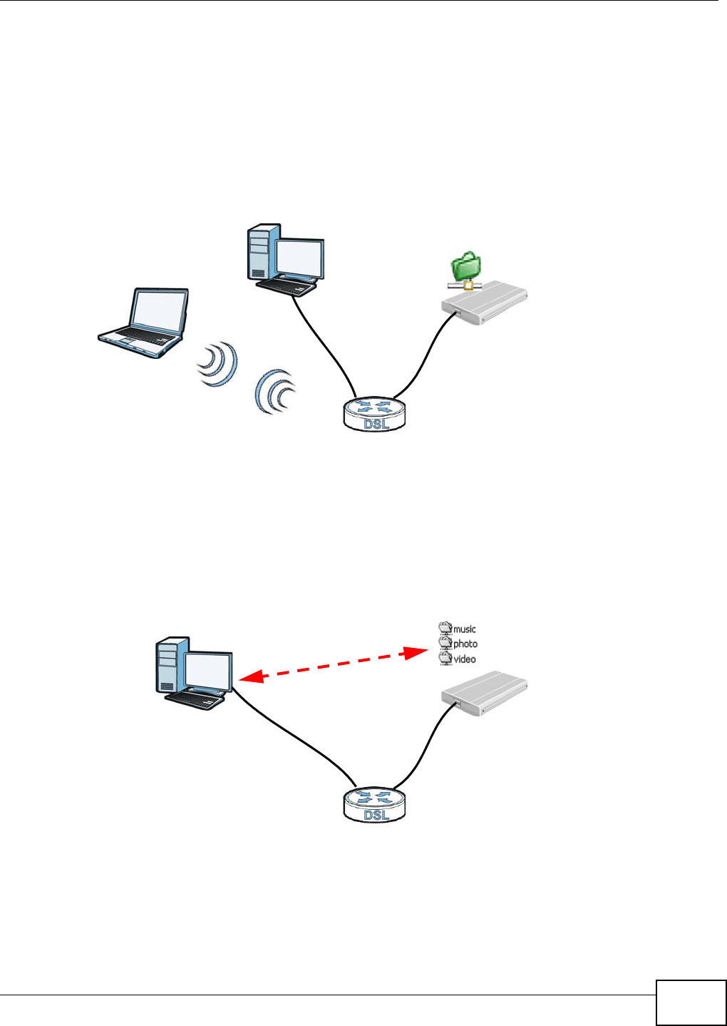
1.4.2 Device’s USB Support
The USB port of t he Device is used for file- sharing, m edia server and print er- sharing.
File Sharing
Use t he built-in USB 2.0 por t t o share files on a USB m em ory st ick or a USB hard drive ( B) . You can
connect one USB hard drive to the Device at a tim e. Use FTP t o access t he files on the USB device.
Figure 2 USB File Sharing Applicat ion
Media Server
You can also use t he Device as a m edia server. This let s anyone on your net work play video, m usic,
and phot os from a USB device ( B) connect ed t o t he Device’s USB port ( without having t o copy them
to another com put er) .
Figure 3 USB Media Server Application
B
A
B
A
Chapter 1 Introducing the Device
VMG8324-B10A / VMG8324-B30A Series User’s Guide
20
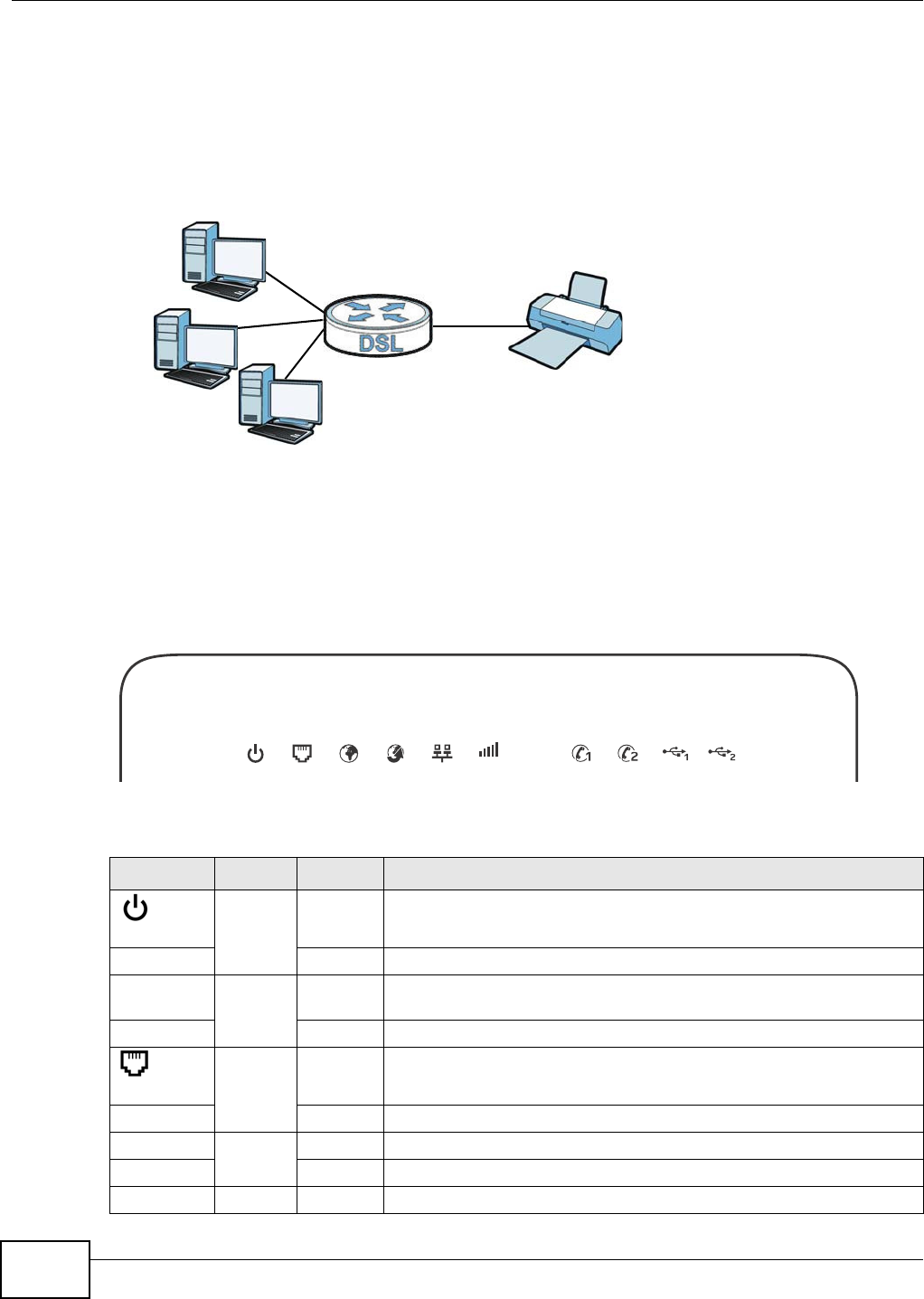
Printer Server
The Device allows you t o shar e a USB print er on your LAN. You can do t his by connecting a USB
print er t o one of the USB por t s on t he Device and t hen configuring a TCP/ I P port on t he com put ers
connect ed to your net w ork.
Figure 4 Sharing a USB Print er
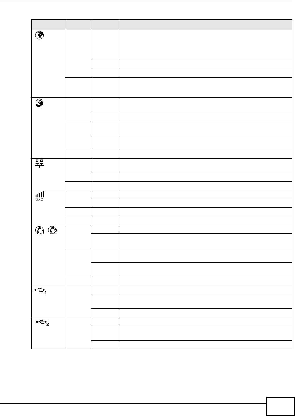
1.5 LEDs (Lights)
The following graphic displays t he labels of t he LEDs.
Figure 5 LEDs on the Device
None of t he LEDs are on if the Device is not receiving power.
Table 1 LED Descript ions
LED COLOR STATUS DESCRIPTION
PWR/ SYS
Green On The Device is receiving pow er and ready for use.
Blinking The Device is self- t est ing.
Red On The Device det ect ed an error while self- t esting, or t here is a device
m alfunct ion.
Off The Device is not receiving power.
DSL
Green On The ADSL line is up.
Blinking The Device is init ializing the ADSL line.
Orange On The VDSL line is up.
Blinking The Device is init ializing the VDSL line.
Off The DSL line is down.
2.4G 5G
Chapter 1 Introducing the Device
VMG8324-B10A / VMG8324-B30A Series User’s Guide 21
I NTERNET
Green On The Device has an I P connect ion but no t raffic.
Your device has a WAN I P address ( eit her st at ic or assigned by a DHCP
server ) , PPP negotiat ion was successfully com plet ed ( if used) and the
DSL connect ion is up.
Blinking The Dev ice is sending or receiving I P traffic.
Off There is no I nt ernet connection or the gateway is in bridged m ode.
Red On The Device at t em pted t o m ake an I P connect ion but failed. Possible
causes are no r esponse from a DHCP ser ver, no PPPoE response, PPPoE
authenticat ion failed.
WAN
Green On The Device has a successful 1000 Mbps Ethernet connect ion on t he
WAN.
Blinking The Device is sending or receiving dat a t o/ from the WAN at 1000 Mbps.
Orange On The Device has a successful 10/ 100 Mbps Ether net connect ion on t he
WAN.
Blinking The Dev ice is sending or receiving dat a t o/ from the WAN at 10/ 100
Mbps.
Off There is no Ethernet connect ion on t he WAN.
LAN
Green On The Device has a successful 1000 Mbps Ether net connect ion with a
dev ice on the Local Area Net work ( LAN) .
Blinking The Device is sending or receiving dat a t o/ from the LAN at 1000 Mbps.
Off The Device does not have an Et hernet connect ion wit h t he LAN.
WiFi 2.4G
Green On The 2.4 GHz wir eless network is act ivated.
Blinking The Device is com m unicat ing w it h ot her wir eless clients.
Orange Blinking The Device is set t ing up a WPS connect ion.
Off The 2.4 GHz wireless network is not act ivated.
Phone1,
Phone2
Green On A SI P account is regist ered for t he phone port .
Blinking A t elephone connect ed t o t he phone port has it s receiver off of the hook
or t here is an incom ing call.
Orange On A SI P account is regist ered for t he phone port and there is a voice
m essage in t he corr esponding SI P account .
Blinking A t elephone connect ed t o t he phone port has it s receiver off of the hook
and there is a voice m essage in t he corresponding SI P account.
Off The phone port does not have a SI P account regist ered.
USB1
Green On The Device recognizes a USB connect ion t hrough t he USB1 slot .
Blinking The Device is sending/ r eceiv ing data to / from t he USB device connected
to it .
Off The Device does not det ect a USB connect ion t hrough t he USB1 slot .
USB2
Green On The Device recognizes a USB connect ion t hrough t he USB2 slot .
Blinking The Device is sending/ r eceiv ing data to / from t he USB device connected
to it .
Off The Device does not det ect a USB connect ion t hrough t he USB2 slot .
Table 1 LED Descript ions ( cont inued)
LED COLOR STATUS DESCRIPTION
Chapter 1 Introducing the Device
VMG8324-B10A / VMG8324-B30A Series User’s Guide
22
1.6 The RESET Button
I f you forget your password or cannot access the Web Configurator, you will need t o use t he RESET
but t on at t he back of t he device t o reload t he factory- default configuration file. This m eans t hat you
will lose all configurat ions that you had previously and the password will be reset to “ 1234”.
1Make sure t he PW R/ SYS LED is on ( not blinking) .
2To set t he device back t o t he fact ory default sett ings, press t he RESET butt on for t en seconds or
unt il the PW R/ SYS LED begins to blink and t hen r elease it . When t he PW R/ SYS LED begins t o
blink, t he default s have been restored and t he device rest art s.
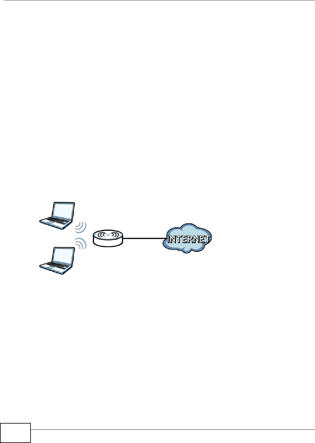
1.7 Wireless Access
The Device is a wireless Access Point ( AP) for wireless client s, such as notebook com put ers or PDAs
and iPads. I t allows t hem t o connect to the I nt ernet wit hout having t o rely on inconvenient Ethernet
cables.
You can configure your w ireless net work in eit her t he built- in Web Configurat or, or using t he WPS
but t on.
Figure 6 Wireless Access Exam ple
1.7.1 Using the Wi-Fi and WPS Buttons
I f t he wir eless net w ork is t urned off, press t he W i- Fi butt on for one second. Once the W iFi 2 .4 G
LED t urns green, the w ireless net work is act ive.
You can also use t he W PS but ton t o quickly set up a secure wireless connection between the Device
and a WPS- com pat ible client by adding one device at a t im e.
To activat e WPS:
1Make sure t he PW R/ SYS LED is on and not blinking.
2Press t he W PS but ton for five seconds and release it.
3Press t he WPS butt on on anot her WPS- enabled device wit hin range of t he Device. The W iFi 2 .4 G
LED flashes orange while t he Device sets up a WPS connection w ith t he ot her wireless device.
Chapter 1 Introducing the Device
VMG8324-B10A / VMG8324-B30A Series User’s Guide 23
4Once t he connection is successfully m ade, t he W iFi 2 .4 G LED shines green.
To turn off t he wireless net work, press the W i- Fi but t on for one t o five seconds. The W iFi 2 .4 G
LED t urns off when t he w ireless net work is off.
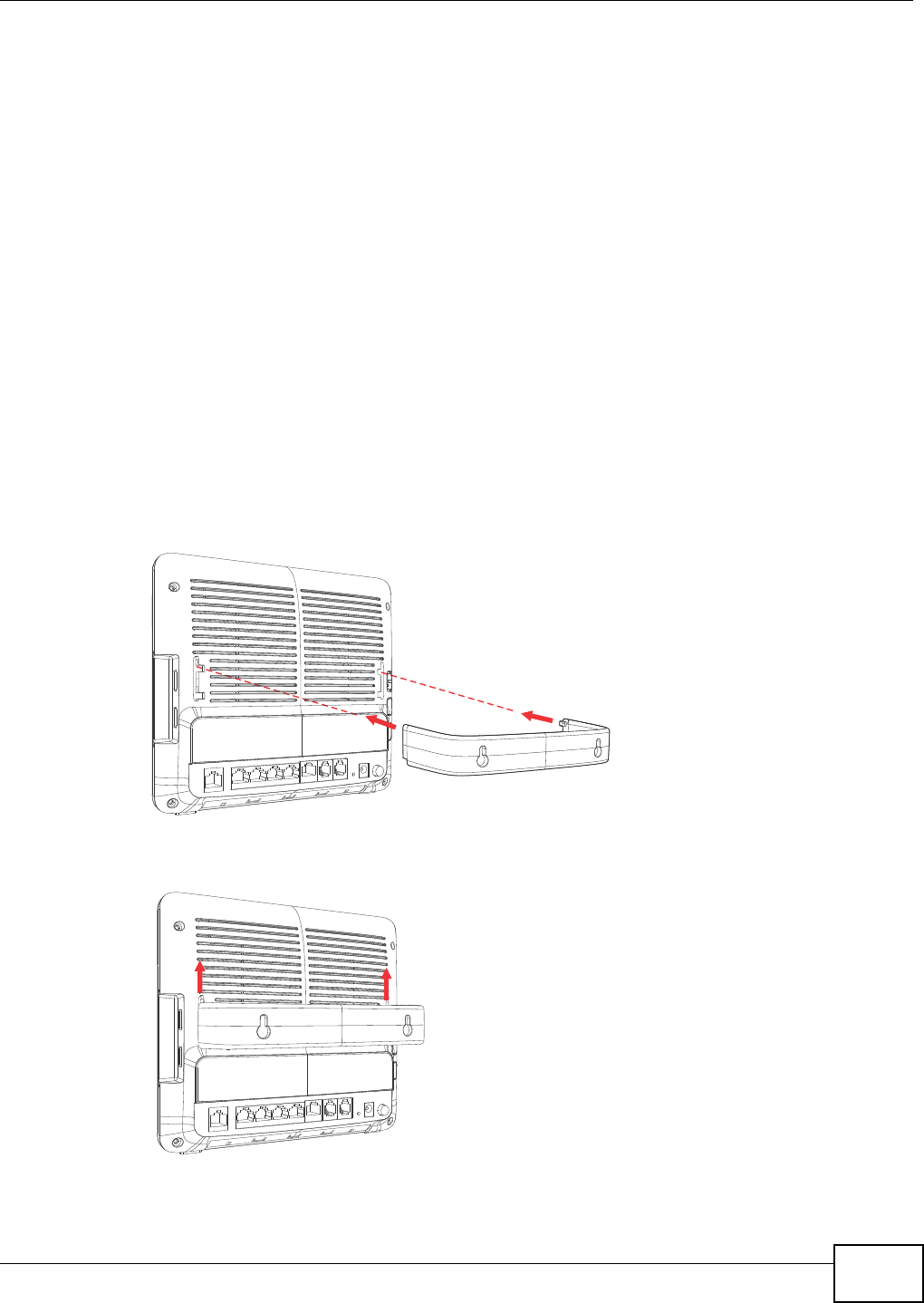
1.8 Wall-mounting Instructions
Do the follow ing t o hang your Device on a wall.
1Locat e a high posit ion on a wall that is free of obst ruct ions. Use a st urdy wall.
2Hold the bracket against t he wall and m ark where t o drill t he holes.
3Drill the two screw holes in the wall.
Be careful to avoid damaging pipes or cables located inside the wall
when drilling holes for the screws.
4Align and insert t he bracket t o the wall- m ount ing not ches on the rear panel of the Device.
5Push t he bracket up t o t ightly att ach it t o t he Device.

Chapter 1 Introducing the Device
VMG8324-B10A / VMG8324-B30A Series User’s Guide
24
6Mount t he Device on the screws w hich are already installed on t he wall. Make sure t hat t he Device
is firm ly at t ached to the screws so it does not fall off.

VMG8324-B10A / VMG8324-B30A Series User’s Guide 25
CHAPTER 2
The Web Configurator
2.1 Overview
The w eb configurat or is an HTML-based m anagem ent int erface that allows easy device set up and
m anagem ent via I nternet brow ser. Use I nternet Explorer 6.0 and lat er versions or Mozilla Firefox 3
and lat er versions or Safari 2.0 and lat er versions. The recom m ended screen resolut ion is 1024 by
768 pixels.
I n order t o use the web configurat or you need to allow :
• Web browser pop- up windows from your device. Web pop- up blocking is enabled by default in
Windows XP SP ( Service Pack) 2.
• JavaScript ( enabled by default ) .
• Java perm issions ( enabled by default) .
See Appendix D on page 365 if you need t o m ake sure these functions ar e allowed in I nt ernet
Explorer.
2.1.1 Accessing the Web Configurator
1Make sure your Device hardware is properly connected ( refer t o t he Quick St art Guide) .
2Launch your web browser. I f t he Device does not aut om at ically re- direct you to the login screen, go
to ht t p: / / 192.168.1.1.
3A password screen displays. To access the adm inist rat ive web configurat or and m anage t he Device,
type t he default usernam e adm in and password 1 2 3 4 in t he passw ord screen and click Login . I f
advanced account security is enabled ( see Section 30.2 on page 289) t he num ber of dots that
appears when you t ype the password changes random ly t o prevent anyone watching the password
field from knowing t he length of your passw ord. I f you have changed the password, ent er your
password and click Login.
Figure 7 Passwor d Scr een
Chapter 2 The Web Configurator
VMG8324-B10A / VMG8324-B30A Series User’s Guide
26
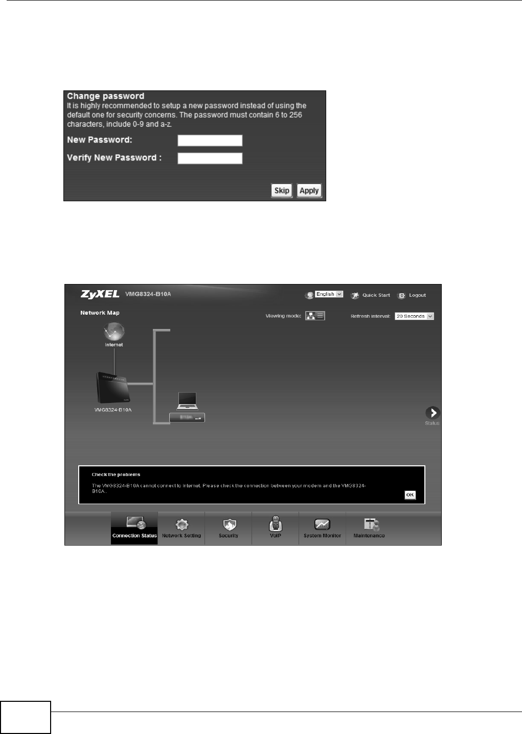
4The following screen displays if you have not yet changed your password. I t is st r ongly
recom m ended you change t he default password. Ent er a new password, ret ype it t o confirm and
click Apply; alt ernat ively click Sk ip t o proceed to the m ain m enu if you do not want t o change t he
password now.
Figure 8 Change Password Screen
5The Qu ick St art W iz a rd screen appears. You can configure t he Device’s t im e zone, basic I nt ernet
access, and wireless sett ings. See Chapt er 3 on page 33 for m ore inform ation.
6Aft er you finished or closed t he Quick St a rt W iza rd screen, t he N et w ork Map page appears.
Figure 9 Network Map
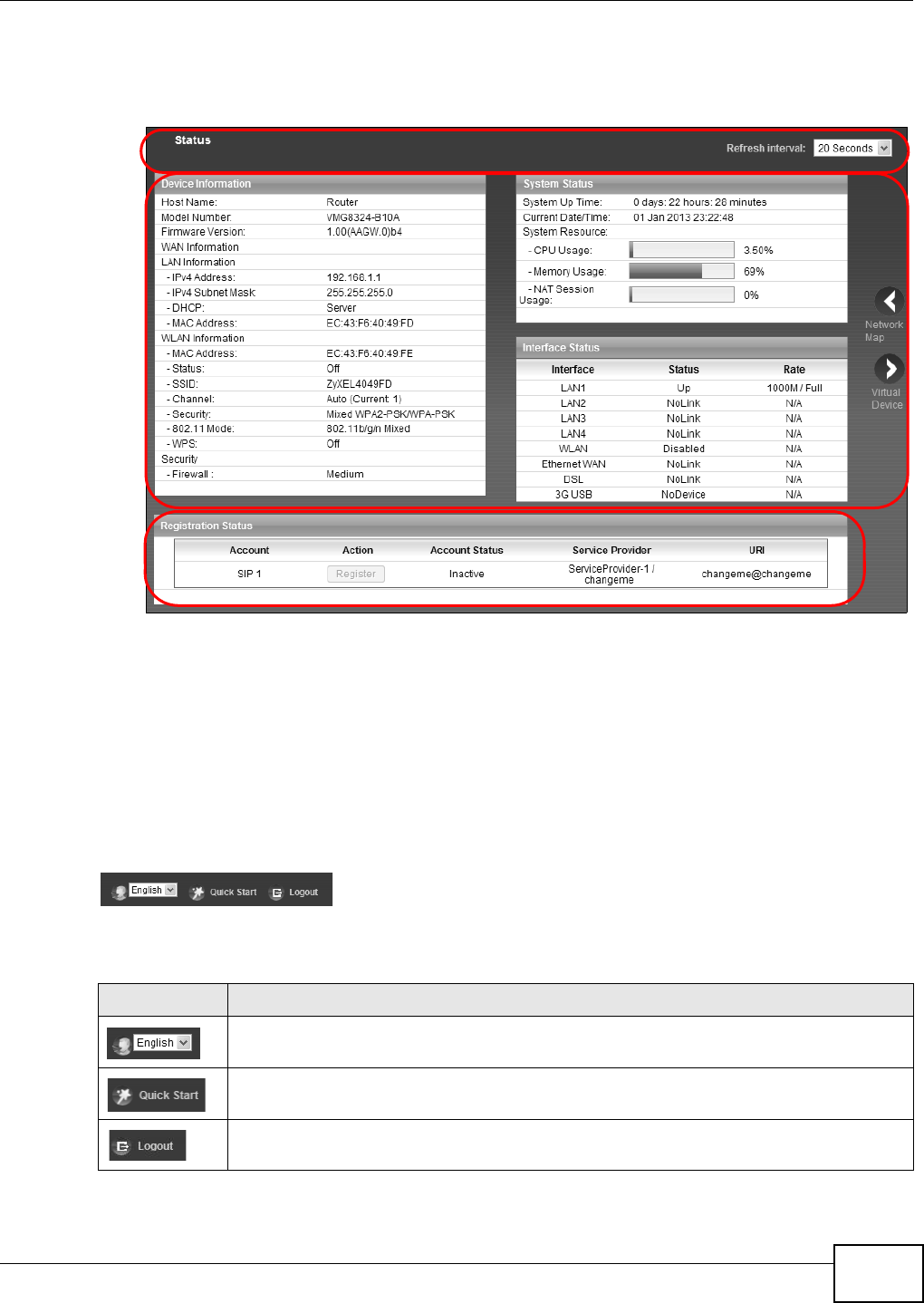
7Click St a t u s to display t he St a t u s screen, where you can view t he Device’s int erface and syst em
inform ation.
Chapter 2 The Web Configurator
VMG8324-B10A / VMG8324-B30A Series User’s Guide 27
2.2 Web Configurator Layout
Figure 10 Screen Layout
As illust rat ed above, t he m ain screen is divided into these part s:
•A - t itle bar
•B - m ain window
•C - navigat ion panel
2.2.1 Title Bar
The t itle bar provides som e icons in the upper right corner.
The icons provide the following functions.
B
C
A
Table 2 Web Configurat or I cons in t he Tit le Bar
ICON DESCRIPTION
Language: Select t he language you prefer.
Quick Start : Click t his icon t o open screens where you can configur e t he Device’s t im e zone
I nt ernet access, and wireless set t ings.
Logout : Click t his icon t o log out of the web configurator.
Chapter 2 The Web Configurator
VMG8324-B10A / VMG8324-B30A Series User’s Guide
28
2.2.2 Main Window
The m ain window displays inform at ion and configurat ion fields. I t is discussed in t he rest of this
docum ent .
Aft er you click St a t u s on t he Connect ion St a t u s page, t he St a t u s screen is displayed. See
Chapter 4 on page 38 for m ore inform at ion about t he St a t us scr een.
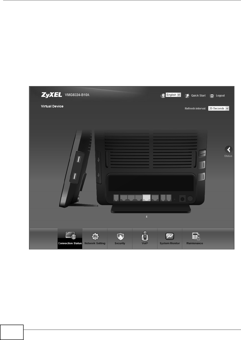
I f you click V ir t ua l D e v ice on t he Syst e m I nfo screen, a visual graphic appears, showing the
connect ion st at us of t he Device’s port s. The connect ed port s are in color and disconnect ed port s are
gray.
Figure 11 Virt ual Device

Chapter 2 The Web Configurator
VMG8324-B10A / VMG8324-B30A Series User’s Guide 29
2.2.3 Navigation Panel
Use t he m enu it em s on the navigat ion panel t o open screens t o configure Device features. The
following tables describe each m enu item .
Table 3 Navigat ion Panel Sum m ary
LINK TAB FUNCTION
Connect ion St atus This screen shows t he net w ork stat us of the Device and com put ers/
devices connect ed to it.
Net work Set t ing
Broadband Br oadband Use t his screen t o view and configure I SP param et ers, WAN I P
addr ess assignm ent , and ot her advanced propert ies. You can also
add new WAN connections.
3G Backup Use t his screen to configur e 3G WAN connect ion.
Advanced Use this screen to enable or disable PTM over ADSL, Annex M/ Annex
J, and DSL PhyR funct ions.
802.1x Use this screen to view and configure the I EEE 802.1x set t ings on t he
Device.
Wan St at u s Use t his screen t o view hist orical t raffic t ransm ission stat ist ics of a
WAN interface.
Wireless General Use this screen to configure t he wireless LAN sett ings and WLAN
authenticat ion/ security set t ings.
More AP Use t his screen t o configure m ultiple BSSs on t he Device.
MAC
Aut hentication
Use t his screen t o block or allow wireless traffic from wireless devices
of cert ain SSI Ds and MAC addresses t o t he Device.
WPS Use this screen to configure and view your WPS ( Wi- Fi Prot ect ed
Set up) settings.
WMM Use this screen to enable or disable Wi- Fi Mult iMedia ( WMM) .
WDS Use t his screen t o set up Wireless Dist ribut ion System ( WDS) links t o
ot her access point s.
Ot hers Use t his screen t o configur e advanced wireless set t ings.
Channel St atus Use this screen to scan w ireless LAN channel noises and view t he
result s.
Hom e
Networking
LAN Setup Use t his screen to configure LAN TCP/ I P set t ings, and ot her advanced
pr opert ies.
St atic DHCP Use t his screen t o assign specific I P addresses t o individual MAC
addr esses.
UPnP Use t his screen t o t ur n UPnP and UPnP NAT-T on or off.
Addit ional
Subnet
Use t his screen to configur e I P alias and public stat ic I P.
STB Vendor I D Use t his screen to have t he Device aut om at ically creat e st at ic DHCP
entries for Set Top Box ( STB) devices when they request I P
addr esses.
5t h Et hernet
port
Use t his screen t o configure the role of the W AN port . I t can be eit her
the Et hernet WAN or a LAN port .
LAN VLAN Use t his screen t o cont rol t he VLAN I D and I EEE 802.1p pr iorit y t ags
of t raffic sent out t hrough individual LAN ports.
Wake on Lan Use this screen to rem ot ely t urn on a device on the net work.

Chapter 2 The Web Configurator
VMG8324-B10A / VMG8324-B30A Series User’s Guide
30
Rou t in g St at ic Rout e Use t his screen to view and set up st at ic routes on t he Device.
DNS Rout e Use t his screen t o forward DNS queries for cert ain dom ain nam es
through a specific WAN int erface t o it s DNS server( s).
Policy
Forwarding
Use t his screen to configur e policy routing on the Dev ice.
RI P Use this screen to configure Rout ing I nform at ion Prot ocol to
exchange rout ing inform at ion with ot her rout ers.
QoS General Use this scr een t o enable QoS and t raffic priorit izing. You can also
configure t he QoS rules and actions.
Queue Set up Use this screen to configure QoS queues.
Class Set up Use t his screen t o define a classifier.
Policer Set u p Use t hese screens t o configure QoS policers.
NAT Port Forwarding Use this scr een t o m ake your local serv ers visible to t he out side
world.
Applicat ions Use t his screen to configur e servers behind t he Dev ice.
Port Triggering Use t his screen t o change your Device’s port triggering sett ings.
DMZ Use t his screen t o configur e a default server which receives packets
from port s that are not specified in t he Port For w ar ding screen.
ALG Use this screen to enable or disable SI P ALG.
Address Mapping Use t his scr een t o change your Device’s address m apping set t ings.
Sessions Use t his screen t o configure the m axim um num ber of NAT sessions
each client host is allowed t o have through t he Device.
DNS DNS Ent ry Use t his screen t o view and configur e DNS routes.
Dynam ic DNS Use t his screen t o allow a st at ic hostnam e alias for a dynam ic I P
addr ess.
I nt er face
Group
Use t his screen t o m ap a port t o a PVC or br idge gr oup.
USB Service File Shar ing Use t his screen t o enable file sharing via the Device.
Media Server Use t his screen t o use t he Device as a m edia server.
Printer Server Use t his screen to enable the print server on the Dev ice and get the
m odel nam e of t he associated print er.
Pow er
Managem ent
Pow er
Managem ent
This scr een is only available for super visors. Use t his screen to
m anually tur n on/ off specific int erface( s) and/ or all LEDs
im m ediat ely.
Aut o Swit ch Off This scr een is only available for super visors. Use t his screen to
configure schedules to have t he Device aut om at ically t urn on/ off
specific int er face( s) and/ or all LEDs.
Securit y Set t ings
Fir ewall General Use t his screen t o configur e t he securit y level of your firewall.
Prot ocol Use t his screen t o add I nt er net services and configure firewall rules.
Access Control Use t his screen t o enable specific t raffic directions for net w ork
services.
DoS Use t his screen t o act ivat e prot ect ion against Denial of Ser vice ( DoS)
at t ack s.
MAC Filter Use t his screen t o block or allow t raffic from devices of cert ain MAC
addr esses t o t he Device.
Table 3 Navigat ion Panel Sum m ary ( continued)
LINK TAB FUNCTION

Chapter 2 The Web Configurator
VMG8324-B10A / VMG8324-B30A Series User’s Guide 31
Par ent al
Cont rol
Use t his screen t o block web sites with t he specific URL.
Scheduler
Rules
Use this screen to configure t he days and t im es when a configured
restrict ion (such as parental cont r ol) is enforced.
Cer t i fi cat es Local Cer t i fi cat es Use t his screen t o view a sum m ary list of cert ificat es and m anage
certificates and cert ificat ion request s.
Trust ed CA Use t his screen t o view and m anage t he list of the t rust ed CAs.
I PSec VPN Set up Use t his screen t o add or edit VPN policies.
Monit or Use t his screen t o view the st at us of all I PSec VPN t unnels. You can
also m anually init iat e a tunnel in t his screen.
VoI P
SI P SI P Account Use t his screen t o set up infor m at ion about your SI P account and
configure audio set t ings such as volum e levels for t he phones
connect ed t o the ZyXEL Device.
SI P Serv ice
Provider Use t his screen t o configure y our ZyXEL Device’s Voice over I P
set t ings.
Phone Use t his screen t o select your location and a call service m ode.
Call Rule Use this screen to configure speed dial for SI P phone num bers that
you call often.
Call History Call Hist ory
Sum m ar y
Use t his screen t o view a call hist ory list .
Call History
Outgoing
Use t his screen t o view det ailed inform at ion for each out going call
you m ade.
Call History
I ncom ing
Use t his screen t o view det ailed inform at ion for each incom ing call
from som eone calling you.
Line Test This scr een is only available for supervisors. Use this screen to do
various t est s for a phone line.
Syst em Monit or
Log Syst em Log Use this scr een t o view t he stat us of event s t hat occur red t o t he
Device. You can ex port or e- m ail the logs.
Securit y Log Use t his screen t o view the login record of t he Dev ice. You can export
or e- m ail the logs.
Traffic St atus WAN Use t his screen t o view t he st at us of all net work t raffic going through
the WAN port of the Device.
LAN Use this screen to view the st at us of all net work traffic going t hrough
t he LAN ports of t he Device.
NAT Use t his screen t o view NAT st at ist ics for connected host s.
Vo I P St at u s Use t his screen t o view VoI P regist rat ion, current call st atust and
phone num bers for t he phone port s.
ARP Table Use t his screen t o view the ARP table. I t displays t he I P and MAC
addr ess of each DHCP connect ion.
Routing Table Use t his screen to view the routing table on the Device.
I GMP/ MLD
Group St at us
Use t his screen t o view the status of all I GMP settings on the Device.
xDSL St at ist ics Use t his screen t o view the Device’s xDSL traffic st at ist ics.
3G Stat ist ics Use t his screen t o look at 3G I nt ernet connect ion st at us.
Maint enance
Table 3 Navigat ion Panel Sum m ary ( continued)
LINK TAB FUNCTION

Chapter 2 The Web Configurator
VMG8324-B10A / VMG8324-B30A Series User’s Guide
32
User Account Use t his screen t o change user passwor d on the Device.
Rem ot e MGMT Use t his screen t o enable specific t raffic directions for net w ork
services.
TR- 069 Client Use t his screen t o configur e the Device t o be m anaged by an Aut o
Configurat ion Ser ver (ACS) .
TR- 064 Use t his screen t o enable m anagem ent via TR-064 on the LAN.
SNMP Use t his scr een t o configure SNMP (Sim ple Net work Managem ent
Prot ocol) set t ings.
Tim e Use t his screen t o change your Device’s t im e and dat e.
Em ail
Notificat ion
Use t his screen to configur e up t o two m ail servers and sender
addr esses on t he Device.
Log Set t ing Use t his screen t o change your Device’s log settings.
Firm war e
Upgrade
Use t his screen t o upload firm ware to your dev ice.
Configurat ion Use this screen to back up and rest ore your dev ice’s configurat ion
( set t ings) or reset the fact or y default set t ings.
Reboot Use t his screen t o reboot t he Device wit hout t urning t he power off.
Diagnostic Ping &
Tr a c e r o u t e &
Nslookup
Use t his screen t o ident ify problem s wit h t he DSL connection. You can
use Ping, TraceRoute, or Nslookup t o help you identify pr oblem s.
802.1ag Use t his screen t o configure CFM ( Connect ivit y Fault Managem ent )
MD ( m aintenance dom ain) and MA (m aint enance association) ,
perform connectivity t est s and view test report s.
OAM Ping Use t his screen t o view inform at ion to help you identify pr oblem s wit h
the DSL connect ion.
Table 3 Navigat ion Panel Sum m ary ( continued)
LINK TAB FUNCTION
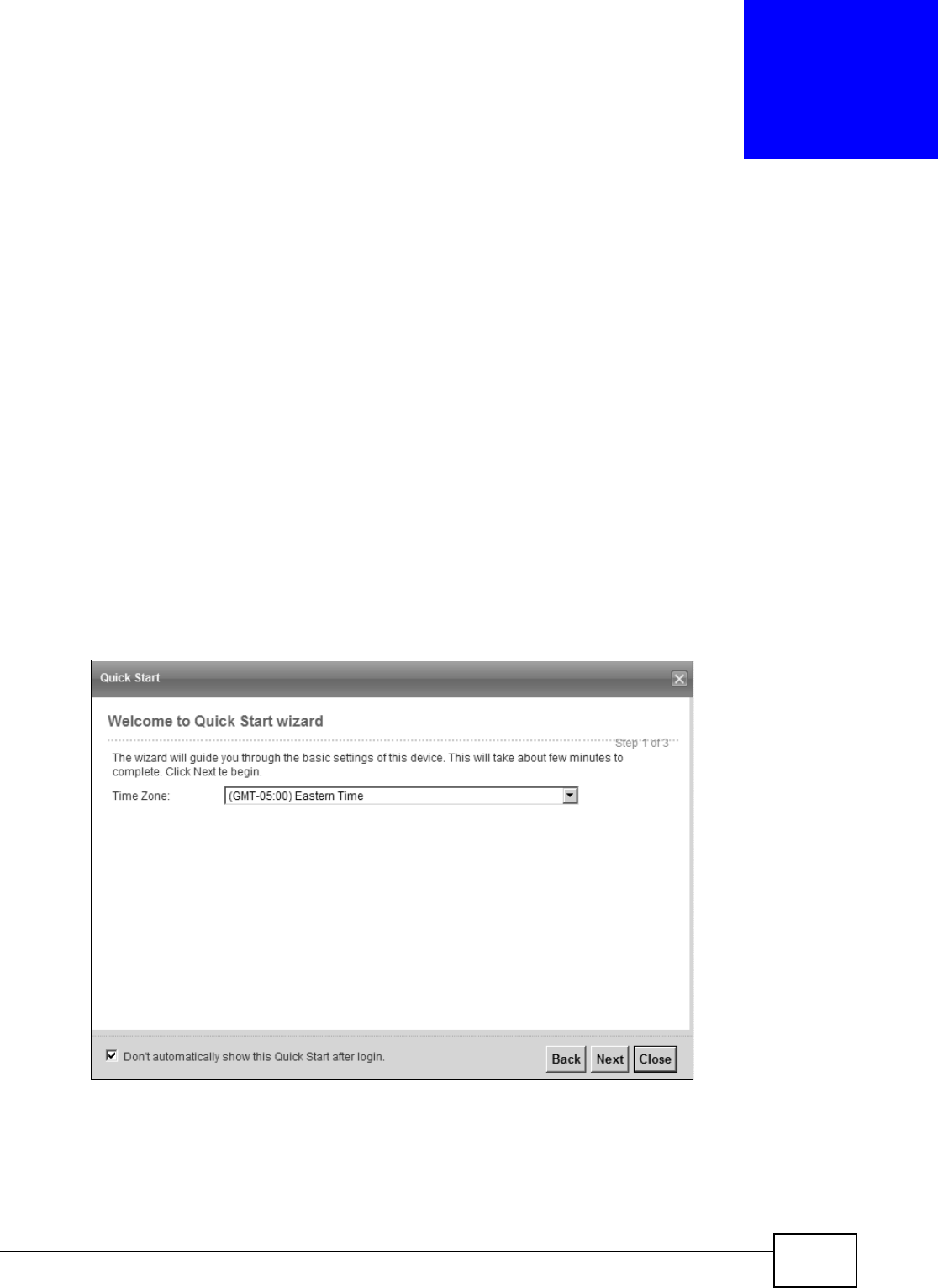
VMG8324-B10A / VMG8324-B30A Series User’s Guide 33
CHAPTER 3
Quick Start
3.1 Overview
Use t he Quick St art screens t o configure the Device’s tim e zone, basic I nt ernet access, and wireless
sett ings.
Not e: See t he technical reference chapt ers (st arting on page 35) for background
inform at ion on the feat ures in t his chapt er.
3.2 Quick Start Setup
1The Quick St art Wizard appears aut om at ically aft er login. Or you can click t he Click St ar t icon in
the top right corner of t he web configurat or t o open the quick st art screens. Select t he t im e zone of
the Device’s location and click N e x t .
Figure 12 Tim e Zone
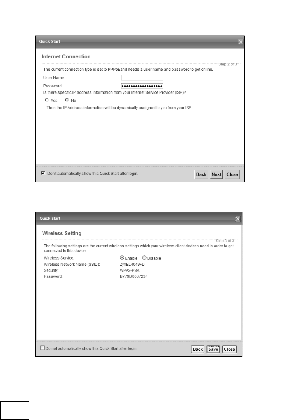
Chapter 3 Quick Start
VMG8324-B10A / VMG8324-B30A Series User’s Guide
34
2Ent er your I nt ernet connect ion inform ation in t his screen. The screen and fields t o ent er m ay vary
depending on your current connect ion t ype. Click N e xt . Click N e x t .
Figure 13 I nt ernet Connect ion
3Tur n the wireless LAN on or off. I f you keep it on, record t he security set t ings so you can configure
your wireless client s to connect t o the Device. Click Save.
Figure 14 I nt ernet Connect ion
4Your Device saves your set t ings and at t em pts t o connect to the I nt ernet .

35
PART II
Technical Reference

36
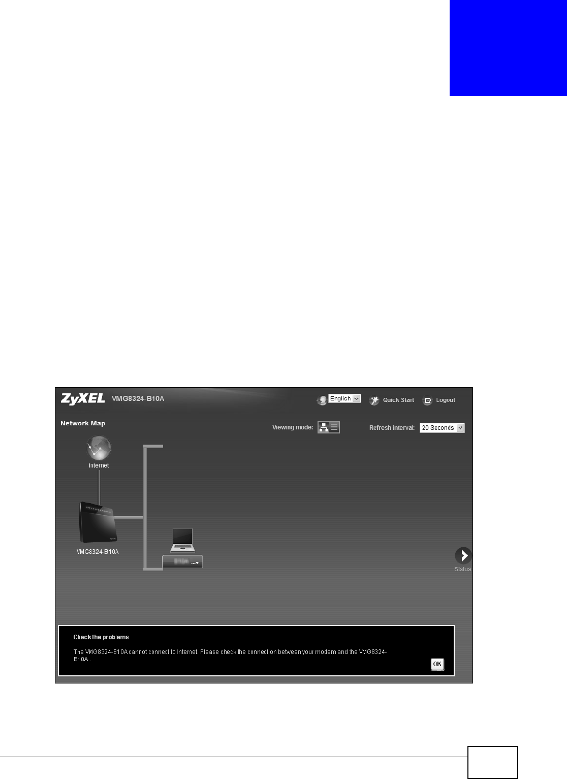
VMG8324-B10A / VMG8324-B30A Series User’s Guide 37
CHAPTER 4
Network Map and Status Screens
4.1 Overview
Aft er you log int o t he Web Configurat or, t he Ne t w or k M a p screen appears. This shows t he network
connect ion st at us of t he Device and client s connect ed t o it .
You can use t he St a t u s screen t o look at t he current stat us of the Device, syst em resources, and
int erfaces ( LAN, WAN, and WLAN) .
4.2 The Network Map Screen
Use t his screen to view t he net work connect ion st at us of the device and its client s. A warning
m essage appears if t here is a connection problem .
Figure 15 Net work Map: I con View Mode
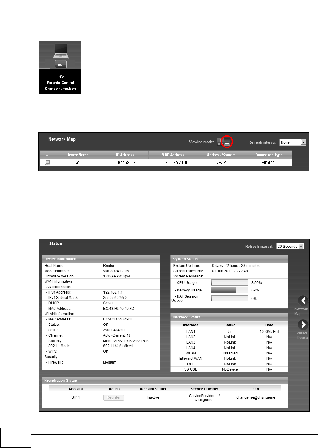
Chapter 4 Network Map and Status Screens
VMG8324-B10A / VMG8324-B30A Series User’s Guide
38
I f you want t o view inform at ion about a client , click the client ’s nam e and I nfo. Click t he I P address
if y ou want t o change it . I f y ou w ant t o change t he nam e or icon of t he client , click Ch a nge na m e/
icon.
I f you prefer to view t he st at us in a list, click List View in the Vie w in g m ode select ion box. You
can configure how oft en you want t he Device to updat e t his screen in Refr esh int e rval.
Figure 16 Net work Map: List View Mode
4.3 The Status Screen
Use t his screen to view the st at us of the Device. Click St a t u s t o open t his screen.
Figure 17 St at us Screen

Chapter 4 Network Map and Status Screens
VMG8324-B10A / VMG8324-B30A Series User’s Guide 39
Each field is described in the following t able.
Table 4 St at us Screen
LABEL DESCRIPTION
Refresh I nt erval Select how oft en you want t he Device t o updat e this screen.
Device I nform at ion
Host Nam e This field displays t he Device sy st em nam e. I t is used for ident ificat ion.
Model Num ber This shows t he m odel num ber of your Device.
Firm war e
Ve r si on
This is t he curr ent version of the fir m ware inside the Device.
WAN I nfor m at ion (These fields display when you have a WAN connect ion.)
WAN Type This field displays t he current WAN connect ion t ype.
MAC Address This shows the WAN Et hernet adapter MAC ( Media Access Cont rol) Addr ess of your
Device.
I P Address This field displays the cur rent I P address of the Device in the WAN. Click Re lea se t o
release your I P address t o 0.0.0.0. I f you want t o r enew your I P address, click Renew .
I P Subnet Mask This field displays the current subnet m ask in the WAN.
Encapsulat ion This field displays t he current encapsulation m ethod.
LAN I nform at ion
I Pv4 Address This is the current I Pv4 I P address of the Device in t he LAN.
I Pv4 Subnet
Mask
This is t he curr ent subnet m ask in the LAN.
DHCP This field displays what DHCP services t he Device is providing t o t he LAN. Choices are:
Ser ve r - The Device is a DHCP server in t he LAN. I t assigns I P addresses t o other
com puter s in t he LAN.
Re lay - The Device act s as a surrogat e DHCP server and relays DHCP r equest s and
responses bet w een t he r em ot e serv er and t he client s.
N on e - The Dev ice is not providing any DHCP services t o t he LAN.
MAC Address This shows t he LAN Ethernet adapt er MAC (Media Access Cont rol) Address of your
Device.
WLAN I nform at ion
MAC Address This show s t he w ireless adapt er MAC (Media Access Cont rol) Address of your Device.
St at us This displays whet her WLAN is act ivat ed.
SSI D This is t he descr ipt iv e nam e used t o identify t he Device in a wireless LAN.
Channel This is t he channel num ber used by t he Device now.
Security This displays the type of securit y m ode t he Device is using in t he wireless LAN.
802.11 Mode This displays the type of 802.11 m ode t he Device is using in t he wireless LAN.
WPS This displays whet her WPS is act ivat ed.
Security
Fir ewall This display s the fir ewall’s current securit y level.
Syst em St atus
Sy st em Up
Tim e
This field displays how long t he Device has been running since it last st art ed up. The
Device st art s up when you plug it in, when you rest art it ( M a int e nance > Reboot ) , or
when you r eset it .
Current Dat e/
Tim e
This field displays the current dat e and t im e in t he Device. You can change this in
M ain t e na n ce> Tim e Se t t ing.
Syst em Resource

Chapter 4 Network Map and Status Screens
VMG8324-B10A / VMG8324-B30A Series User’s Guide
40
CPU Usage This field displays what percent age of t he Device’s processing ability is current ly used.
When t his percent age is close to 100% , t he Device is running at full load, and the
throughput is not going t o im prove anym ore. I f you want som e applications t o have
m ore t hroughput , you should t urn off ot her applicat ions ( for exam ple, using QoS; see
Chapt er 9 on page 139) .
Mem ory Usage This field displays what percent age of t he Device’s m em ory is current ly used. Usually,
this percentage should not increase m uch. I f m em ory usage does get close t o 100% , t he
Device is probably becom ing unst able, and you should rest art the device. See Sect ion
39.2 on page 313, or t urn off the device (unplug t he pow er) for a few seconds.
NAT Session
Usage
This field displays what percent age of the Device support ed NAT sessions are cur rent ly
being used.
I nterface St at us
I nt erface This colum n displays each interface t he Device has.
St at us This field indicates t he int erface’s use status.
For the DSL interface, t his field displays Dow n ( line down) , Up ( line up or connect ed)
and Dr op (dropping a call) if you're using PPPoE encapsulat ion.
For t he Et hernet WAN and LAN interface, this field display s Up when using the int erface
and N oLin k when not using t he int erface.
For t he WLAN int erface, t his field displays t he enabled ( Act iv e ) or disabled ( I n Act iv e)
st ate of the int erface.
For t he 3G USB interface, t his field displays Up when using the int erface and N oD ev ice
when no device is det ect ed in any USB slot.
Rat e For t he Ethernet WAN and LAN int erface, t his display s t he por t speed and duplex set t ing.
For the DSL interface, it displays the downst ream and upst ream t ransm ission rat e.
For the WLAN interface, it displays t he m ax im um t ransm ission rate or N / A wit h WLAN
disabled.
For the 3G USB interface, this field displays Up when a 3G USB device is inst alled in a
USB slot and N o De vice when no device is detected in any USB slot .
Regist r at ion St at us
Account This colum n displays each SI P account in t he Dev ice.
Act ion I f t he SI P account is already registered wit h t he SI P server, t he Account St a t us field
display s Regist e r ed.
Click Unr egist er t o delet e t he SI P account’s regist rat ion in t he SI P ser ver. This does not
cancel your SI P account , but it delet es t he m apping between your SI P ident it y and your
I P addr ess or dom ain nam e.
I f t he SI P account is not registered wit h t he SI P server, t he Accou nt Status field
display s N ot Regist e r ed.
Click Re gist e r t o have t he Device at t em pt t o r egist er the SI P account with t he SI P
server.
The but t on is grayed out if t he SI P account is disabled.
Table 4 St at us Screen ( cont inued)
LABEL DESCRIPTION

Chapter 4 Network Map and Status Screens
VMG8324-B10A / VMG8324-B30A Series User’s Guide 41
Account Status This field displays the current registration status of t he SI P account . You have t o regist er
SI P account s wit h a SI P server t o use VoI P.
I n a ct ive - The SI P account is not act ive. You can activate it in VoI P > SI P > SI P
Accou nt .
N ot Re gist ere d - The last t im e t he Device t r ied to register the SI P account wit h the
SI P server, t he at tem pt failed. Use t he Re gist e r but t on t o r egister t he account again.
The Device autom at ically tries to register the SI P account when you turn on the Device
or w hen you act ivat e it.
Re gist e red - The SI P account is already regist ered wit h the SI P server. You can use it
to m ake a VoI P call.
Service- Pr ov ider This colum n displays the service pr ovider nam e and SI P num ber for each SI P account .
URI This field displays t he account num ber and service dom ain of the SI P account . You can
change t hese in the VoI P > SI P scr eens.
Table 4 St at us Screen ( cont inued)
LABEL DESCRIPTION

Chapter 4 Network Map and Status Screens
VMG8324-B10A / VMG8324-B30A Series User’s Guide
42
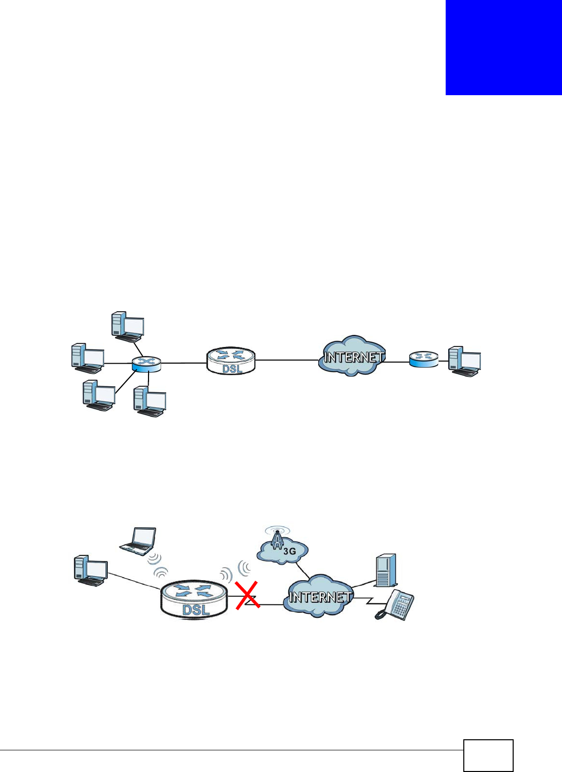
VMG8324-B10A / VMG8324-B30A Series User’s Guide 43
CHAPTER 5
Broadband
5.1 Overview
This chapt er discusses t he Device’s Br oadba n d screens. Use t hese screens to configure your
Device for I nternet access.
A WAN ( Wide Area Net work) connect ion is an out side connect ion to another net wor k or t he
I nt ernet . I t connects your privat e networks, such as a LAN ( Local Area Network) and other
net works, so that a com put er in one locat ion can com m unicate with com puters in ot her locat ions.
Figure 18 LAN and WAN
3G ( t hird generat ion) st andards for t he sending and receiving of voice, video, and dat a in a m obile
environm ent .
You can at tach a 3G wireless adapt er t o t he USB port and set t he Device t o use this 3G connect ion
as your WAN or a backup w hen t he wired WAN connection fails.
Figure 19 3G WAN Connect ion
5.1.1 What You Can Do in this Chapter
• Use the Broadband screen t o view, rem ove or add a WAN int erface. You can also configure t he
WAN sett ings on t he Device for I nt ernet access ( Sect ion 5.2 on page 47) .
• Use the 3 G Ba ck up screen t o configure 3G WAN connection ( Sect ion 5.3 on page 57) .
WAN

Chapter 5 Broadband
VMG8324-B10A / VMG8324-B30A Series User’s Guide
44
• Use the Adva nced screen to enable or disable PTM over ADSL, Annex M/ Annex J, and DSL PhyR
functions ( Sect ion 5.4 on page 61) .
• Use the 8 0 2 .1 x screen t o view and configure the I EEE 802.1X sett ings on t he Device (Sect ion
5.5 on page 62) .
• Use the W an St a t us scr een t o view a WAN int erface’s hist orical t raffic t ransm ission rate.
(Sect ion 5.6 on page 63) .
5.1.2 What You Need to Know
The following t erm s and concept s m ay help as you read t his chapt er.
Encapsulation Method
Encapsulation is used t o include data from an upper layer prot ocol into a lower layer prot ocol. To set
up a WAN connect ion to the I nt ernet , you need t o use the sam e encapsulat ion m et hod used by your
I SP ( I nt ernet Service Provider) . I f your I SP offers a dial- up I nternet connection using PPPoE (PPP
over Ethernet) , t hey should also provide a usernam e and password ( and service nam e) for user
aut hent icat ion.
Table 5 WAN Setup Overview
LAYER-2 INTERFACE INTERNET CONNECTION
CONNECTION DSL LINK
TYPE MODE ENCAPSULATION CONNECTION SETTINGS
ADSL/ VDSL
over PTM
N/ A Rout ing PPPoE PPP inform at ion, I Pv4/ I Pv6 I P
addr ess, rout ing feat ure, DNS
ser ver, VLAN, QoS, and MTU
I PoE I Pv4/ I Pv6 I P addr ess, rout ing
feat ure, DNS server, VLAN, QoS,
and MTU
Bridge N/ A VLAN and QoS
ADSL over ATM EoA Routing PPPoE/ PPP0A ATM PVC configurat ion, PPP
inform ation, I Pv 4/ I Pv6 I P address,
rout ing featur e, DNS server, VLAN,
QoS, and MTU
I PoE/ I PoA ATM PVC configurat ion, I Pv4/ I Pv6
I P addr ess, rout ing feat ure, DNS
ser ver, VLAN, QoS, and MTU
Bridge N/ A ATM PVC configurat ion, and QoS
EtherWAN N/ A Rout ing PPPoE PPP user nam e and password, WAN
I Pv4/ I Pv6 I P address, routing
feat ure, DNS server, VLAN, QoS,
and MTU
I PoE WAN I Pv4/ I Pv6 I P address, NAT,
DNS server and rout ing feat ure
Bridge N/ A VLAN and QoS

Chapter 5 Broadband
VMG8324-B10A / VMG8324-B30A Series User’s Guide 45
WAN IP Address
The WAN I P address is an I P address for t he Device, which m akes it accessible from an out side
net work. I t is used by t he Device to com m unicat e w ith ot her devices in ot her net works. I t can be
st at ic ( fixed) or dynam ically assigned by t he I SP each t im e t he Device t ries t o access the I nt ernet .
I f your I SP assigns you a static WAN I P address, t hey should also assign you t he subnet m ask and
DNS ser ver I P address( es) .
ATM
Asynchronous Transfer Mode ( ATM) is a WAN net w orking technology t hat provides high- speed dat a
transfer. ATM uses fixed- size packet s of inform at ion called cells. With ATM, a high QoS ( Quality of
Service) can be guarant eed. ATM uses a connect ion- orient ed m odel and est ablishes a virtual circuit
( VC) between Finding Out More
PTM
Packet Transfer Mode (PTM) is packet- orient ed and supported by t he VDSL2 standard. I n PTM,
packet s are encapsulat ed direct ly in the High- level Dat a Link Cont rol ( HDLC) fram es. I t is designed
to pr ovide a low-overhead, t ransparent way of t ransport ing packet s over DSL links, as an
alternat ive t o ATM.
3G
3G ( Third Generation) is a digital, packet- swit ched wireless technology. Bandwidth usage is
opt im ized as m ult iple users share the sam e channel and bandwidt h is only allocat ed t o users when
t h ey send dat a. I t allow s fast t ransfer of v oice and non- voice dat a and provides broadband I nt ernet
access t o m obile devices.
IPv6 Introduction
I Pv6 ( I nternet Prot ocol version 6) , is designed t o enhance I P address size and features. The
increase in I Pv6 address size to 128 bit s ( from t he 32-bit I Pv4 address) allows up t o 3.4 x 1038 I P
addresses. The Device can use I Pv4/ I Pv6 dual stack to connect to I Pv4 and I Pv6 networks, and
supports I Pv6 rapid deploym ent ( 6RD) .
IPv6 Addressing
The 128-bit I Pv6 address is writt en as eight 16- bit hexadecim al blocks separat ed by colons ( : ) . This
is an exam ple I Pv6 address 2001:0db8:1a2b:0015:0000:0000:1a2f:0000.
I Pv6 addresses can be abbreviat ed in two ways:
• Leading zeros in a block can be om it t ed. So
2001:0db8:1a2b:0015:0000:0000:1a2f:0000 can be writ t en as
2001:db8:1a2b:15:0:0:1a2f:0.
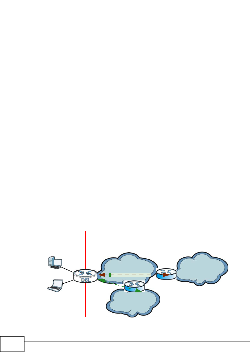
Chapter 5 Broadband
VMG8324-B10A / VMG8324-B30A Series User’s Guide
46
• Any num ber of consecutive blocks of zeros can be replaced by a double colon. A double
colon can only appear once in an I Pv6 address. So
2001:0db8:0000:0000:1a2f:0000:0000:0015 can be writ t en as
2001:0db8::1a2f:0000:0000:0015, 2001:0db8:0000:0000:1a2f::0015,
2001:db8::1a2f:0:0:15 or 2001:db8:0:0:1a2f::15.
IPv6 Prefix and Prefix Length
Sim ilar t o an I Pv4 subnet m ask, I Pv6 uses an addr ess prefix to represent t he network address. An
I Pv6 prefix length specifies how m any m ost significant bits ( st art from the left) in t he address
com pose t he net w ork address. The prefix lengt h is writ t en as “ / x” where x is a num ber. For
exam ple,
2001:db8:1a2b:15::1a2f:0/32
m eans t hat t he first 32 bits (2001:db8) is the subnet prefix.
IPv6 Subnet Masking
Both an I Pv6 address and I Pv6 subnet m ask com pose of 128- bit binary digits, w hich are divided
int o eight 16- bit blocks and writ t en in hexadecim al notat ion. Hexadecim al uses four bits for each
charact er ( 1 ~ 10, A ~ F). Each block’s 16 bit s are t hen represent ed by four hexadecim al
charact ers. For exam ple, FFFF: FFFF: FFFF: FFFF: FC00: 0000: 0000: 0000.
IPv6 Rapid Deployment
Use I Pv6 Rapid Deploym ent ( 6rd) when t he local network uses I Pv6 and t he I SP has an I Pv4
net work. When t he Device has an I Pv4 WAN address and you set I Pv6 / I Pv 4 M ode to I Pv4 Only,
you can enable 6rd to encapsulate I Pv6 packet s in I Pv4 packet s t o cross t he I SP’s I Pv4 net work.
The Device generat es a global I Pv6 prefix from its I Pv4 WAN address and t unnels I Pv6 traffic t o t he
I SP’s Border Relay rout er ( BR in t he figure) t o connect t o t he nat ive I Pv6 I nternet . The local
net work can also use I Pv4 services. The Device uses it ’s configured I Pv4 WAN I P t o rout e I Pv4
traffic t o t he I Pv4 I nt ernet .
Figure 20 I Pv6 Rapid Deploym ent
I SP ( I Pv4)
I Pv6 I nternet
I Pv4
I Pv6
BR
I Pv6 in I Pv4
I Pv4 I nternet
I Pv4
+
LAN
- I Pv6
- I Pv4
W AN
- I Pv4
- I Pv6 in I Pv4
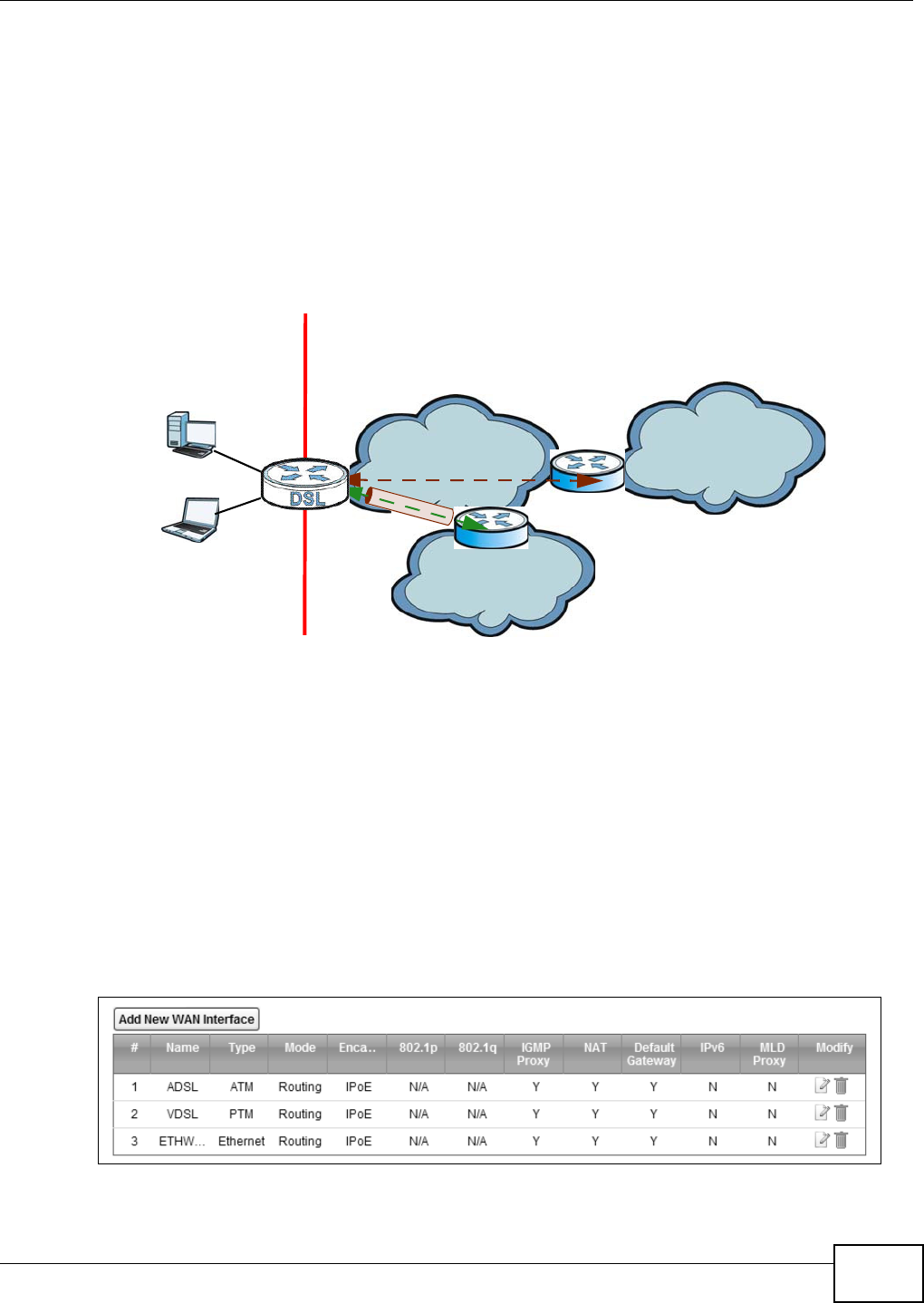
Chapter 5 Broadband
VMG8324-B10A / VMG8324-B30A Series User’s Guide 47
Dual Stack Lite
Use Dual St ack Lit e when local network com put ers use I Pv4 and t he I SP has an I Pv6 network.
When t he Device has an I Pv6 WAN address and you set I Pv6 / I Pv4 M ode t o I Pv6 Only, you can
enable Dual St ack Lit e t o use I Pv4 com put ers and services.
The Device t unnels I Pv4 packet s inside I Pv6 encapsulation packet s t o t he I SP’s Address Fam ily
Transit ion Rout er ( AFTR in t he graphic) t o connect t o t he I Pv4 I nt ernet . The local net work can also
use I Pv6 services. The Device uses it ’s configured I Pv6 WAN I P t o rout e I Pv6 t raffic t o t he I Pv6
I nt ernet .
Figure 21 Dual St ack Lit e
5.1.3 Before You Begin
You need t o know your I nt ernet access set t ings such as encapsulation and WAN I P address. Get t his
inform ation from your I SP.
5.2 The Broadband Screen
Use t his screen to change your Device’s I nt ernet access set t ings. Click N et w or k Set t ing >
Broa dband from t he m enu. The sum m ary t able shows you t he configured WAN services
( connections) on the Device.
Figure 22 Net work Set t ing > Broadband
I SP ( I Pv6) I Pv6 I nternet
I Pv6
AFTR
I Pv4 in I Pv6
I Pv4 I nt ernet
I Pv6 I Pv4
+
LAN
- I Pv6
- I Pv4
W AN
- I Pv6
- I Pv4 in I Pv6

Chapter 5 Broadband
VMG8324-B10A / VMG8324-B30A Series User’s Guide
48
The following t able describes t he labels in this screen.
Table 6 Network Sett ing > Broadband
LABEL DESCRIPTION
Add New WAN
I nterface
Click t his but t on t o create a new connection.
# This is the index num ber of t he ent r y.
Nam e This is the service nam e of t he connect ion.
Type This shows whet her it is an ATM, Ethernet or a PTM connect ion.
Mode This shows whet her t he connection is in rout ing or bridge m ode.
Encapsulation This is t he m et hod of encapsulat ion used by t his connect ion.
802.1p This indicat es the 802.1p priority level assigned to traffic sent t hrough this connect ion. This
display s N / A when there is no priorit y level assigned.
802.1q This indicat es the VLAN I D num ber assigned t o t raffic sent through t his connect ion. This
display s N / A when there is no VLAN I D num ber assigned.
I GMP Prox y This shows whether t he Device act as an I GMP proxy on t his connect ion.
NAT This shows whether NAT is act ivat ed or not for t his connection.
Default
Gateway
This shows whet her t he Device use the WAN interface of t his connect ion as the syst em
default gateway.
I Pv6 This shows whet her I Pv6 is act ivat ed or not for t his connect ion. I Pv6 is not available when
the connection uses the bridging service.
MLD Proxy This shows whet her Multicast Listener Discovery ( MLD) is activat ed or not for this
connection. MLD is not available when t he connect ion uses the bridging service.
Modify Click the Ed it icon t o configure t he WAN connect ion.
Click the D ele t e icon to rem ove t he WAN connect ion.
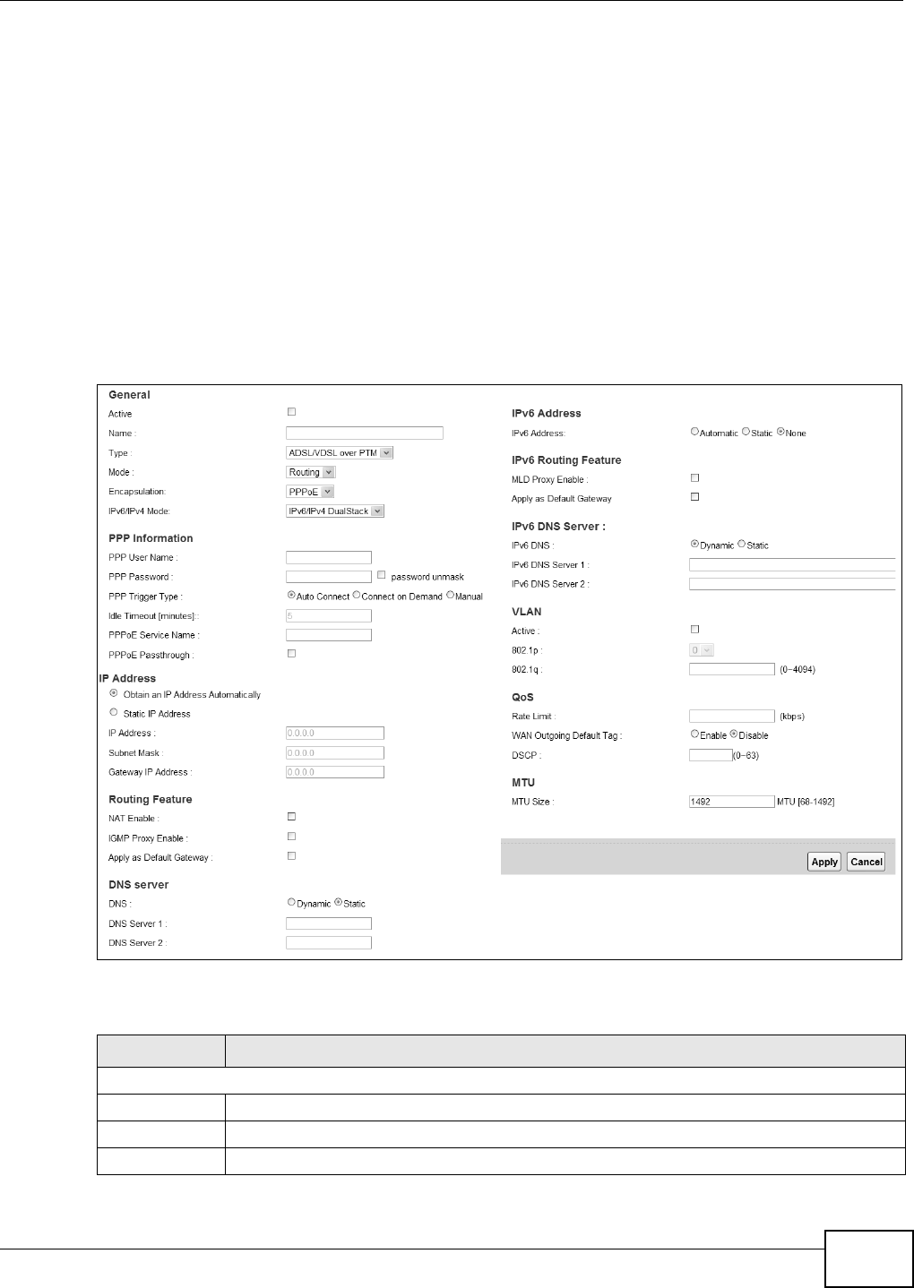
Chapter 5 Broadband
VMG8324-B10A / VMG8324-B30A Series User’s Guide 49
5.2.1 Add/Edit Internet Connection
Click Add N e w W AN I nt er fa ce in t he Broa dband screen or t he Edit icon next t o an exist ing WAN
int erface t o configure a WAN connection. The screen varies depending on t he int erface type, m ode,
encapsulation, and I Pv6/ I Pv4 m ode you select .
5.2.1.1 Routing Mode
Use Rou t in g m ode if your I SP give you one I P address only and you want m ultiple com put ers t o
share an I nt ernet account.
The following exam ple screen displays when you select t he ADSL/ V D SL over ATM connect ion
type, Ro ut in g m ode, and PPPoE encapsulat ion. The screen varies when you select ot her interface
type, encapsulation, and I Pv6/ I Pv4 m ode.
Figure 23 Net work Set t ing > Broadband > Add New WAN I nt er face/ Edit ( Rout ing Mode)
The following t able describes t he labels in this screen.
Table 7 Network Sett ing > Broadband > Add New WAN I nt erface/ Edit ( Rout ing Mode)
LABEL DESCRIPTION
General
Act ive Select this t o act ivat e t he WAN configurat ion set t ings.
Nam e Specify a descript ive nam e for this connect ion.
Type Select whether it is an ADSL/ VDSL over PTM, ADSL over ATM connect ion or Et hernet .

Chapter 5 Broadband
VMG8324-B10A / VMG8324-B30A Series User’s Guide
50
Mode Select Rou t in g if your I SP give you one I P address only and you want m ult iple com puters t o
shar e an I nt ernet account .
Encapsulat ion Select the m ethod of encapsulat ion used by your I SP from t he drop- down list box . This
option is available only when you select Ro ut in g in t he M od e field.
The choices depend on the connection t ype you select ed. I f your connect ion t ype is ADSL/
VD SL over PTM , t he choices are PPPoE and I PoE. I f your connect ion t ype is AD SL ove r
ATM , t he choices are PPPoE, PPPoA, I PoE and I PoA.
I Pv6/ I Pv4 Mode Select I Pv4 On ly if you want t he Device t o run I Pv4 only.
Select I Pv6 / I Pv4 Dua lSt a ck t o allow t he Dev ice to run I Pv4 and I Pv6 at t he sam e tim e.
Select I Pv6 Only if you want the Device t o run I Pv6 only.
ATM PVC Configuration (These fields appear when t he Type is set t o ADSL over ATM .)
VPI The valid range for the VPI is 0 to 255. Ent er the VPI assigned t o you.
VCI The valid range for the VCI is 32 to 65535 (0 to 31 is reserved for local m anagem ent of ATM
traffic) . Ent er t he VCI assigned to you.
DSL Link Type This field is not edit able. The select ion depends on t he set t ing in t he En ca psu la t io n field.
EoA ( Et hernet over ATM) uses an Ethernet header in t he packet , so t hat you can have
m ult iple services/ connect ions over one PVC. You can set each connect ion to have its own
MAC address or all connections share one MAC address but use different VLAN I Ds for
different services. EoA support s ENET ENCAP (I PoE), PPPoE and RFC1483/ 2684 bridging
encapsulation m et hods.
PPPoA ( PPP over ATM) allows j ust one PPPoA connect ion over a PVC.
I PoA (I P over ATM) allow s j ust one RFC 1483 rout ing connection over a PVC.
Encapsulat ion
Mode
Select t he m et hod of m ultiplexing used by your I SP from t he drop- down list box. Choices
are:
•LLC/ SN AP- BRI D GI N G: I n LCC encapsulat ion, bridged PDUs are encapsulat ed by
ident ifying the t ype of t he br idged m edia in the SNAP header. This is available only when
you select I PoE or PPPoE in t he Sele ct DSL Lin k Type field.
•VC/ M UX: I n VC m ultiplex ing, each prot ocol is car ried on a single ATM virtual circuit
( VC). To transport m ult iple prot ocols, t he Device needs separat e VCs. There is a binding
between a VC and t he t y pe of t he net work pr ot ocol carried on t he VC. This reduces
pay load overhead since there is no need t o carry prot ocol inform at ion in each Prot ocol
Dat a Unit ( PDU) payload.
•LLC/ EN CAPSU LAT I ON : More t han one prot ocol can be carried over the sam e VC. This
is available only when you select PPPoA in the En ca p su la t ion field.
•LLC/ SN AP- ROUTI N G: I n LCC encapsulation, an I EEE 802.2 Logical Link Cont rol ( LLC)
header is pr efixed to each rout ed PDU t o ident ify the PDUs. The LCC header can be
followed by an I EEE 802.1a SubNet w ork At t achm ent Point ( SNAP) header. This is
available only when you select I PoA in the Enca psu lat ion field.
Service
Category
Select UBR W it hou t PCR or UBR W it h PCR for applicat ions t hat are non- t im e sensit ive,
such as e- m ail.
Select CBR ( Cont inuous Bit Rat e) t o specify fixed ( alway s- on) bandwidth for voice or data
traffic.
Select N on Re a lt im e VBR ( non real- tim e Variable Bit Rate) for connect ions t hat do not
require closely controlled delay and delay variat ion.
Select Re a ltim e VBR (real- t im e Variable Bit Rat e) for applications with bursty connect ions
t hat require closely controlled delay and delay variat ion.
Peak Cell Rat e Divide t he DSL line rate ( bps) by 424 (the size of an ATM cell) t o find t he Peak Cell Rat e
( PCR). This is the m axim um rat e at which the sender can send cells. Type t he PCR here.This
field is not available when you select UBR W it h out PCR.
Table 7 Network Sett ing > Broadband > Add New WAN I nt erface/ Edit ( Rout ing Mode) ( continued)
LABEL DESCRIPTION

Chapter 5 Broadband
VMG8324-B10A / VMG8324-B30A Series User’s Guide 51
Sust ainable
Cell Rate
The Sust ainable Cell Rate ( SCR) set s t he av erage cell rate ( long-term ) t hat can be
transm itt ed. Type t he SCR, which m ust be less t han t he PCR. Not e t hat syst em default is 0
cells/ sec.
This field is available only when you select Non Re a ltim e V BR or Re a lt im e VBR.
Max im um Bur st
Size
Maxim um Burst Size ( MBS) refers to the m axim um num ber of cells t hat can be sent at t he
peak rat e. Type t he MBS, which is less t han 65535.
This field is available only when you select Non Re a ltim e V BR or Re a lt im e VBR.
PPP I nform at ion ( This is available only when you select PPPoE or PPPoA in t he M ode field.)
PPP User Nam e Ent er the user nam e exact ly as your I SP assigned. I f assigned a nam e in t he form
user@dom ain where dom ain ident ifies a service nam e, then ent er bot h com ponent s exact ly
as given.
PPP Passwor d Ent er the password associat ed with the user nam e above. Select passw or d unm ask to
show your entered password in plain text .
PPP Triger Type Select when to have t he Device est ablish t he PPP connection.
Auto Connect - select this t o not let t he connect ion t im e out .
Conn ect on De m and - select this t o aut om at ically bring up t he connect ion w hen the
Device receives packets destined for t he I nt ernet.M anu a l - select this if you want t o
m anually t rigger t he connect ion up.
I dle Tim eout This value specifies t he t im e in m inut es that elapses before t he r out er aut om atically
disconnect s from t he PPPoE server.
This field is not configurable if you select Aut o Conne ct in t he PPP Trige r Type field.
PPPoE Service
Nam e
Ent er t he nam e of your PPPoE service here.
PPPoE
Passt h roug h
This field is available when you select PPPoE encapsulation.
I n addit ion t o t he Dev ice’s bu ilt- in PPPoE clien t , you can enable PPPoE pass t hrough t o allow
up to t en host s on t he LAN t o use PPPoE client soft ware on t heir com put er s t o connect to t he
I SP v ia t he Device. Each host can have a separat e account and a public WAN I P address.
PPPoE pass through is an alt er nat ive t o NAT for applicat ion where NAT is not appropr iat e.
Disable PPPoE pass thr ough if you do not need t o allow host s on t he LAN to use PPPoE client
soft ware on t heir com puters to connect t o t he I SP.
I P Address ( This is available only when you select I Pv4 Only or I Pv 6 / I Pv 4 Du a lStack in t he I Pv 6 / I Pv 4
Mode field.)
Obtain an I P
Address
Aut om at ically
A stat ic I P addr ess is a fixed I P t hat your I SP gives you. A dynam ic I P address is not fixed;
t he I SP assigns you a different one each tim e you connect t o t he I nternet. Select t his if you
have a dynam ic I P address.
DHCP
opt ion 60/
Ven d o r I D
This field displays when edit ing an exist ing WAN int erface. Type t he class vender I D you
want t he Device to add in the DHCP Discovery packet s that go to the DHCP server.
DHCP
opt ion 43
Enable
This field displays when editing an exist ing WAN int erface. Ty pe t he vender specific
inform at ion you want t he Dev ice to add in t he DHCP Offer packet s. The infor m at ion is used,
for exam ple, for configuring an ACS’s ( Auto Configurat ion Server) URL.
St atic I P
Address
Select t his option I f t he I SP assigned a fixed I P address.
I P Address Ent er t he st at ic I P address provided by your I SP.
Subnet
Mask
Ent er t he subnet m ask provided by your I SP.
Gat eway I P
Address
Ent er t he gat eway I P addr ess provided by your I SP.
Table 7 Network Sett ing > Broadband > Add New WAN I nt erface/ Edit ( Rout ing Mode) ( continued)
LABEL DESCRIPTION

Chapter 5 Broadband
VMG8324-B10A / VMG8324-B30A Series User’s Guide
52
Rout ing Feat ure (This is available only when you select I Pv4 On ly or I Pv6 / I Pv4 Dua lSt a ck in t he I Pv6 /
I Pv4 M ode field.)
NAT Enable Select t his opt ion t o act ivat e NAT on t his connect ion.
I GMP Proxy
Enable
I nt er net Group Multicast Pr ot ocol (I GMP) is a networ k- layer prot ocol used t o establish
m em bership in a Mult icast group - it is not used to carry user dat a.
Select this opt ion to have the Device act as an I GMP pr oxy on this connect ion. This allow s
t he Device t o get subscr ibing inform ation and m aint ain a j oined m em ber list for each
m ulticast gr oup. I t can r educe m ulticast traffic significant ly.
Apply as
Default
Gateway
Select this opt ion t o have t he Device use t he WAN int erface of t his connection as t he syst em
default gateway.
DNS Server ( This is available only when you select I Pv4 Only or I Pv6 / I Pv4 Du a lSt a ck in the I Pv6 / I Pv4
Mode field.)
DNS Select D yn am ic if you want t he Device use t he DNS server addresses assigned by your I SP.
Select St a t ic if you want t he Device use t he DNS ser ver addresses you configure m anually.
DNS Server 1 Ent er t he fir st DNS server addr ess assigned by t he I SP.
DNS Server 2 Enter t he second DNS server address assigned by t he I SP.
WAN MAC Addr ess
Fact or y
Default
Select Factory Defa ult t o use t he factory assigned default MAC address.
Clone t he
com put er ’s
MAC
addr ess - I P
Address
Select t his option and ent er t he I P address of t he com puter on t he LAN whose MAC you are
cloning. I t is advisable to clone t he MAC address from a com puter on your LAN even if your
I SP does not present ly require MAC address aut hent icat ion.
Set WAN
MAC
Address
Select t his opt ion and ent er the MAC address you want t o use.
Tunnel ( This is available only when you select I Pv 4 On ly or I Pv6 Only in t he I Pv6 / I Pv4 Mode field.)
The DS- Lite ( Dual St ack Lit e) fields display when you set the I Pv6 / I Pv4 Mode field t o I Pv6 Only.
Enable Dual St ack Lit e t o let local com puters use I Pv4 t hrough an I SP’s I Pv6 network. See Dual St ack Lite on
page 47 for m ore inform at ion.
The 6RD ( I Pv6 rapid deploym ent ) fields display when you set the I Pv6 / I Pv4 M ode field to I Pv4 Only. See
I Pv6 Rapid Deploym ent on page 46 for m ore inform at ion.
Enable DS- Lite This is available only when you select I Pv6 Only in t he I Pv6 / I Pv4 M ode field. Select
Enable t o let local com put er s use I Pv 4 t hrough an I SP’s I Pv6 net work.
DS- Lit e Relay
Server I P
Specify the t ransition router ’s I Pv6 address.
Enable 6RD This is available only when you select I Pv4 Only in t he I Pv6 / I Pv4 Mode field. Select
Enable t o t unnel I Pv6 t raffic fr om t he local net w ork through t he I SP’s I Pv4 net work.
6RD Type Select St a t ic if you have t he I Pv4 address of the relay server, ot herwise select DH CP t o
have t he Device det ect it aut om atically t hrough DHCP.
I Pv4 Mask
Lengt h
Ent er the subnet m ask num ber ( 1~ 32) for t he I Pv4 network.
6RD Border
Relay Server I P
When you set the 6 RD Type to St a t ic, specify t he relay server ’s I Pv4 address in this field.
6RD I Pv6 Prefix Ent er an I Pv6 prefix for t unneling I Pv6 t raffic t o t he I SP’s border relay router and connect ing
to t he nat ive I Pv6 I nt ernet .
I Pv6 Address ( This is available only when you select I Pv6 / I Pv4 Dua lSt a ck or I Pv 6 Only in t he I Pv6 / I Pv4
Mode field.)
Table 7 Network Sett ing > Broadband > Add New WAN I nt erface/ Edit ( Rout ing Mode) ( continued)
LABEL DESCRIPTION

Chapter 5 Broadband
VMG8324-B10A / VMG8324-B30A Series User’s Guide 53
I Pv6 Addr ess Select Au t om a t ic if you want t o have t he Device use t he I Pv6 prefix from t he connect ed
rout er’s Rout er Advert isem ent ( RA) to generat e an I Pv6 address.
• Select Ge t I Pv6 Address Fr om D H CPv6 Ser v e r( I A_ N A) i f y ou w a n t t o obt ain an I Pv 6
addr ess from a DHCPv6 server. The I P address assigned by a DHCPv6 server has priorit y
over t he I P address aut om at ically generat ed by the Dev ice using t he I Pv 6 prefix from an
RA. This opt ion is available only when you choose t o get your I Pv6 addr ess
aut om at ically.
• Select Pr efix Delega t ion( I A_ PD) to use DHCP PD ( Prefix Delegat ion) which enables
the Device t o pass t he I Pv 6 pr efix inform at ion t o its LAN host s. The host s can t hen use
the prefix t o generat e t heir I Pv6 addresses.
Select St a t ic if you have a fixed I Pv6 address assigned by your I SP.
Select N on e t o not assign any I Pv6 address t o t his WAN connect ion.
WAN I Pv6
Address
Ent er t he I Pv6 address assigned by your I SP.
Prefix
Length
Ent er t he address prefix lengt h t o specify how m any m ost significant bit s in an I Pv6 add r ess
com pose t he net w ork address.
Next Hop Enter t he I P address of t he next- hop gat eway. The gat eway is a rout er or swit ch on t he
sam e segm ent as your Device's inter face( s) . The gateway helps forward packets t o t heir
dest inations.
I Pv6 Routing Feature ( This is available only when you select I Pv6 / I Pv4 Dua lSt a ck or I Pv6 Only in t he
I Pv6 / I Pv4 M ode field. You can enable I Pv6 routing feat ures in t he follow ing sect ion.)
MLD Proxy
Enable
Select t h is check box t o have t h e Dev ice act as an MLD pr ox y on t his connect ion. This allow s
the Device t o get subscript ion inform ation and m aintain a j oined m em ber list for each
m ulticast gr oup. I t can r educe m ulticast traffic significant ly.
Apply as
Default
Gateway
Select this opt ion t o have t he Device use t he WAN int erface of t his connection as t he syst em
default gateway.
I Pv6 DNS
Server
Configure the I Pv6 DNS server in t he follow ing sect ion.
I Pv6 DNS Select Dy nam ic t o have t he Device get the I Pv 6 DNS server addr esses from t he I SP
aut om at ically.
Select St a t ic t o have t he Device use t he I Pv6 DNS server addresses you configure
m anually.
I Pv6 DNS
Server 1
Ent er t he first I Pv6 DNS server address assigned by t he I SP.
I Pv6 DNS
Server 2
Enter t he second I Pv6 DNS server address assigned by t he I SP.
VLAN ( These fields appear when t he Type is set t o ADSL/ V D SL ov er PTM .)
Active Select this opt ion to add the VLAN tag (specified below) t o t he outgoing traffic t hrough t his
connect ion .
802.1p I EEE 802.1p defines up to 8 separat e t raffic types by inserting a tag into a MAC-layer fram e
that contains bits t o define class of serv ice.
Select the I EEE 802.1p priority level (from 0 to 7) to add t o t raffic t hrough t his connect ion.
The great er t he num ber, t he higher the priority lev el.
802.1q Type the VLAN I D num ber ( from 1 t o 4094) for t raffic thr ough this connection.
QoS
Rat e Lim it Ent er the rate lim it for the connect ion. This is t he m axim um t ransm ission rate allowed for
traffic on this connection.
WAN Out going
Default Tag
Select Ena ble and ent er a D SCP ( DiffSer v Code Point ) value t o have t he Device add it in the
packet s sent by t his WAN interface.
Table 7 Network Sett ing > Broadband > Add New WAN I nt erface/ Edit ( Rout ing Mode) ( continued)
LABEL DESCRIPTION
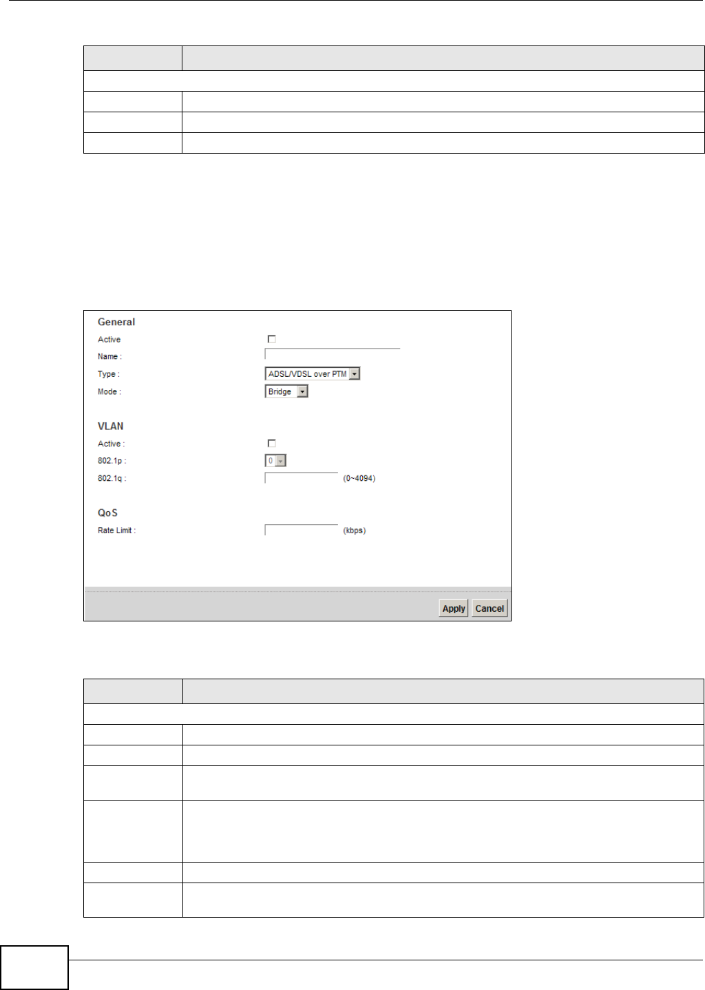
Chapter 5 Broadband
VMG8324-B10A / VMG8324-B30A Series User’s Guide
54
5.2.1.2 Bridge Mode
Click t he Add n e w W AN I nt e rfa ce in the N e t w ork Se t t ing > Br oadba n d screen or t he Ed it icon
next t o the connect ion you want t o configure. Select Br idge as t he encapsulat ion m ode. The screen
varies depending on the int erface type you select.
I f you select ADSL/ V D SL ove r PTM as t he int erface t ype, the following scr een appears.
Figure 24 Net work Set t ing > Broadband > Add New WAN I nt er face/ Edit ( Bridge Mode )
The following t able describes t he fields in this screen.
MTU
MTU Size Ent er t he MTU ( Maxim um Transfer Unit ) size for t his t raffic.
Apply Click Apply t o save your changes back to t he Device.
Cancel Click Ca nce l t o exit t his screen w it hout saving.
Table 7 Network Sett ing > Broadband > Add New WAN I nt erface/ Edit ( Rout ing Mode) ( continued)
LABEL DESCRIPTION
Table 8 Network Sett ing > Broadband > Add New WAN I nt erface/ Edit ( Bridge Mode)
LABEL DESCRIPTION
General
Act ive Select this t o act ivat e t he WAN configuration settings.
Nam e Ent er a service nam e of t he connect ion.
Ty p e Select AD SL/ VDSL over PTM as t he interface t hat you want t o configure. The Device uses
the VDSL technology for data t ransm ission over t he DSL port .
Mode Select Bridge w hen your I SP provides you m or e than one I P address and you want the
connect ed com put ers t o get individual I P address fr om I SP’s DHCP ser ver dir ectly. I f you
select Br idge , you cannot use rout ing funct ions, such as QoS, Firewall, DHCP server and
NAT on traffic from t he select ed LAN port ( s).
VLAN This section is available only when you select ADSL/ V D SL ov er PTM in t he Type field.
Active Select this t o add the VLAN Tag ( specified below) t o the outgoing traffic t hrough t his
connect ion.
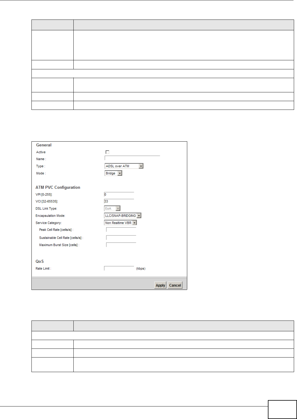
Chapter 5 Broadband
VMG8324-B10A / VMG8324-B30A Series User’s Guide 55
I f you select ADSL over ATM as t he interface t ype, t he following scr een appears.
Figure 25 Net work Set t ing > Broadband > Add New WAN I nt erface/ Edit ( ADSL over ATM- Bridge
Mode)
The following t able describes t he fields in this screen.
802.1p I EEE 802.1p defines up to 8 separat e t raffic types by insert ing a tag into a MAC- layer fram e
that contains bit s t o define class of serv ice.
Select t he I EEE 802.1p priorit y level ( from 0 t o 7) t o add to t raffic t hrough t his connect ion.
The great er the num ber, t he higher the pr iority level.
802.1q Type t he VLAN I D num ber ( from 0 t o 4094) for traffic t hrough t his connect ion.
QoS
Rat e Lim it Enter the rate lim it for the connection. This is the m axim um t ransm ission rate allowed for
traffic on t his connect ion.
Apply Click Apply t o save your changes.
Cancel Click Ca nce l to ex it t his scr een wit hout sav ing.
Table 9 Network Sett ing > Broadband > Add New WAN I nt erface/ Edit ( ADSL over ATM - Bridge
Mode)
LABEL DESCRIPTION
General
Act ive Select this t o act ivat e t he WAN configuration settings.
Nam e Ent er a service nam e of t he connect ion.
Ty p e Select ADSL ove r ATM as t he int er face for which you want to configure here. The Dev ice
uses the ADSL t echnology for dat a transm ission over the DSL por t .
Table 8 Network Sett ing > Broadband > Add New WAN I nt erface/ Edit ( Bridge Mode) ( cont inued)
LABEL DESCRIPTION

Chapter 5 Broadband
VMG8324-B10A / VMG8324-B30A Series User’s Guide
56
Mode Select Bridge w hen your I SP provides you m or e than one I P address and you want the
connect ed com put ers t o get individual I P address fr om I SP’s DHCP ser ver dir ectly. I f you
select Br idge , you cannot use rout ing funct ions, such as QoS, Firewall, DHCP server and
NAT on traffic from t he select ed LAN port ( s).
ATM PVC Configuration (These fields appear when t he Type is set t o ADSL over ATM .)
VPI The valid range for t he VPI is 0 to 255. Ent er t he VPI assigned t o you.
VCI The valid range for t he VCI is 32 to 65535 ( 0 t o 31 is reserved for local m anagem ent of ATM
traffic). Ent er t he VCI assigned t o you.
DSL Link Type This field is not edit able. The select ion depends on t he set t ing in t he En ca psu la t io n field.
EoA ( Ethernet over ATM) uses an Ethernet header in t he packet , so that you can have
m ultiple serv ices/ connect ions over one PVC. You can set each connect ion to have its ow n
MAC address or all connections share one MAC address but use different VLAN I Ds for
different ser vices. EoA supports ENET ENCAP ( I PoE), PPPoE and RFC1483/ 2684 bridging
encapsulation m et hods.
PPPoA ( PPP over ATM) allows j ust one PPPoA connect ion over a PVC.
I PoA ( I P over ATM) allows j ust one RFC 1483 rout ing connection over a PVC.
Encapsulat ion
Mode
Select the m et hod of m ult iplexing used by your I SP from t he drop- down list box. Choices
are:
•LLC/ SN AP- BRI D GI N G: I n LCC encapsulat ion, bridged PDUs ar e encapsulated by
identifying the type of t he bridged m edia in t he SNAP header. This is available only when
you select I PoE or PPPoE in the Select DSL Link Type field.
•VC/ M UX: I n VC m ult iplexing, each pr ot ocol is carried on a single ATM virt ual cir cuit
(VC). To t ransport m ult iple protocols, t he Device needs separat e VCs. There is a binding
between a VC and t he t ype of t he net work prot ocol carried on t he VC. This reduces
payload overhead since t here is no need t o carry prot ocol inform at ion in each Prot ocol
Dat a Unit ( PDU) payload.
•LLC/ EN CAPSU LATI ON : More than one pr ot ocol can be carried over the sam e VC. This
is available only when you select PPPoA in the En ca p su la t ion field.
•LLC/ SN AP- ROUTI N G: I n LCC encapsulation, an I EEE 802.2 Logical Link Control ( LLC)
header is prefixed t o each r out ed PDU t o ident ify t he PDUs. The LCC header can be
followed by an I EEE 802.1a SubNet w ork At t achm ent Point ( SNAP) header. This is
available only when you select I PoA in t he Enca psu lation field.
Service
Category
Select UBR W it h out PCR or UBR W ith PCR for applicat ions t hat are non-tim e sensit ive,
such as e- m ail.
Select CBR ( Continuous Bit Rat e) t o specify fixed ( always- on) bandwidt h for voice or data
traffic.
Select N on Re a ltim e V BR ( non r eal- tim e Variable Bit Rat e) for connect ions t hat do not
require closely contr olled delay and delay variat ion.
Select Rea ltim e VBR ( real- t im e Var iable Bit Rat e) for applicat ions with burst y connect ions
that require closely cont rolled delay and delay variation.
Peak Cell Rat e Divide t he DSL line rat e ( bps) by 424 (the size of an ATM cell) to find the Peak Cell Rat e
( PCR). This is the m axim um rat e at which the sender can send cells. Type t he PCR her e.This
field is not available when you select UBR W it h out PCR.
Su st ai nab le Cel l
Rat e
The Sustainable Cell Rate (SCR) sets t he av erage cell rat e ( long-t erm ) t hat can be
transm it t ed. Type t he SCR, which m ust be less t han t he PCR. Note that system default is 0
cells/ sec.
This field is available only when you select N on Rea lt im e VBR or Re a lt im e VBR.
Maxim um Burst
Size
Maxim um Burst Size ( MBS) refers t o t he m axim um num ber of cells t hat can be sent at the
peak rate. Type t he MBS, which is less t han 65535.
This field is available only when you select N on Rea lt im e VBR or Re a lt im e VBR.
Table 9 Network Sett ing > Broadband > Add New WAN I nt erface/ Edit ( ADSL over ATM - Bridge
Mode) ( continued)
LABEL DESCRIPTION
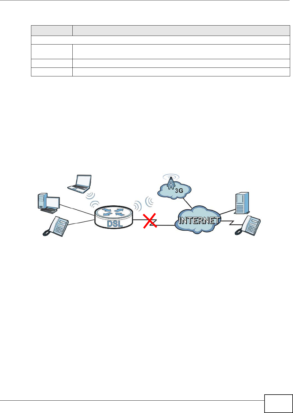
Chapter 5 Broadband
VMG8324-B10A / VMG8324-B30A Series User’s Guide 57
5.3 The 3G Backup Screen
The USB port s ( at the left side panel of the Device) allow you t o at t ach a 3G dongle to wirelessly
connect to a 3G net work for I nt ernet access. You can have t he Device use t he 3G WAN connect ion
as a backup. Disconnect the DSL and Ethernet WAN ports t o use the 3G dongle as your prim ary
WAN connect ion. The Device aut om atically uses a w ired WAN connect ion when available.
Not e: This Device supports connecting one 3G dongle at a tim e.
Figure 26 I nt ernet Access Applicat ion: 3G WAN
Use t his screen t o configure your 3G sett ings. Click N e t w or k Se t t ing > Broadba nd > 3 G
Back up.
QoS
Rat e Lim it Enter the rate lim it for the connection. This is the m axim um t ransm ission rate allowed for
traffic on t his connect ion.
Apply Click Apply t o save your changes.
Cancel Click Ca nce l to ex it t his scr een wit hout sav ing.
Table 9 Network Sett ing > Broadband > Add New WAN I nt erface/ Edit ( ADSL over ATM - Bridge
Mode) ( continued)
LABEL DESCRIPTION
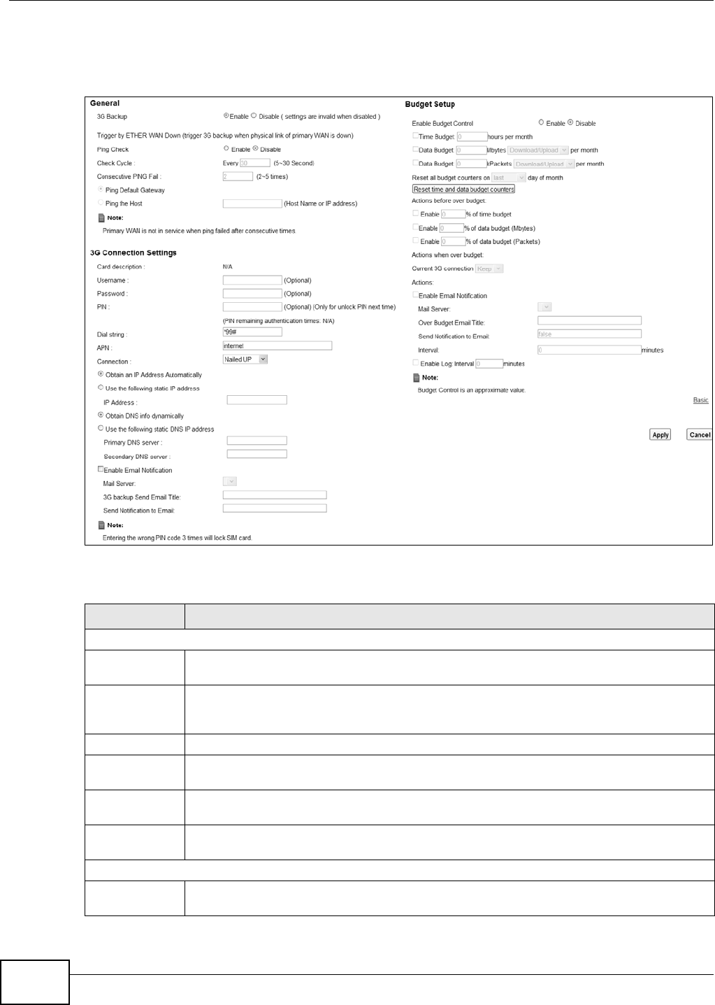
Chapter 5 Broadband
VMG8324-B10A / VMG8324-B30A Series User’s Guide
58
Not e: The act ual dat a rate you obtain varies depending t he 3G card you use, t he signal
st rengt h t o t he service provider’s base st ation, and so on.
Figure 27 Net work Set t ing > Broadband > 3G Backup
The following t able describes t he labels in this screen.
Table 10 Net work Sett ing > Broadband > 3G Backup
LABEL DESCRIPTION
General
3G Backup Select Enable t o have t he Device use t he 3G connect ion as your WAN or a backup when the
wir ed WAN connection fails.
Ping Check Select Enable if you want the Device t o ping check t he connect ion stat us of your WAN. You
can configure t he frequency of t he ping check and num ber of consecut ive failures before
triggering 3G backup.
Check Cycle Ent er the fr equency of the ping check in t his field.
Consecutive
PI NG Fail
Ent er how m any consecutive failures are required befor e 3G backup is t riggered.
Ping Default
Gateway
Select this to have t he Device ping t he WAN interface’s default gateway I P address.
Ping the Host Select t his t o have the Device ping t he par t icular host nam e or I P address you t yped in t his
field.
3G Connection Set t ings
Card
description
This field displays the m anufact urer and m odel nam e of your 3G card if you inser t ed one in
the Dev ice. Otherwise, it display s N / A.

Chapter 5 Broadband
VMG8324-B10A / VMG8324-B30A Series User’s Guide 59
Usernam e Type t he user nam e ( of up t o 64 ASCI I print able characters) given to you by your ser vice
pr ovider.
Password Type t he password ( of up t o 64 ASCI I print able charact ers) associated with the user nam e
above.
PI N A PI N (Personal I dent ificat ion Num ber ) code is a key t o a 3G card. Wit hout t he PI N code,
you cannot use t he 3G card.
I f your I SP enabled PI N code aut hent icat ion, ent er the 4- digit PI N code ( 0000 for exam ple)
pr ovided by your I SP. I f you ent er the PI N code incorrectly, t he 3G card m ay be blocked by
your I SP and y ou cannot use t he account t o access the I nt ernet .
I f your I SP disabled PI N code authenticat ion, leave t his field blank.
Dial str ing Ent er t he phone num ber ( dial st ring) used t o dial up a connection to your service pr ovider ’s
base st at ion. Your I SP should provide t he phone num ber.
For exam ple, * 99# is the dial st ring to est ablish a GPRS or 3G connect ion in Taiwan.
APN Enter t he APN (Access Point Nam e) pr ovided by your service provider. Connect ions with
different APNs m ay provide different services ( such as I nt ernet access or MMS ( Mult i- Media
Messaging Service) ) and char ge m et hod.
You can ent er up t o 32 ASCI I print able charact er s. Spaces are allowed.
Connect ion Select N ailed UP if you do not want t he connect ion t o t im e out .
Select on D em a n d if you do not want the connection up all t he t im e and specify an idle
tim e- out in t he M a x I dle Tim eou t field.
Max I dle
Tim eout
This value specifies t he t im e in m inut es that elapses before t he Device aut om atically
disconnect s from the I SP.
Obtain an I P
Address
Aut om at ically
Select this option if your I SP did not assign you a fixed I P addr ess.
Use t he
following st at ic
I P address
Select t his option if t he I SP assigned a fixed I P address.
I P Address Ent er your WAN I P addr ess in this field if you select ed Use t h e follow ing st a t ic I P
addr e ss.
Obtain DNS
info
dynam ically
Select this t o have t he Device get t he DNS server addresses from the I SP aut om at ically.
Use t he
following st at ic
DNS I P address
Select this to have t he Device use t he DNS server addresses you configure m anually.
Prim ary
DNS server
Ent er t he fir st DNS server address assigned by t he I SP.
Secondary
DNS server
Ent er t he second DNS serv er address assigned by t he I SP.
Enable Em ail
Notification
Select this to enable the e- m ail not ificat ion funct ion. The Device will e- m ail you a
not ificat ion when t he 3G connection is up.
Mail Ser ver Select a m ail server for the e- m ail address specified below.
I f you do not select a m ail server, e-m ail not ificat ions cannot be sent via e-m ail. You m ust
have configured a m ail server already in t he Main t e na n ce > Em ail N ot ifica t ion screen.
3G backup
Send Email
Tit le
Type a t it le t hat you want t o be in t he subject line of the e- m ail notificat ions t hat t he Device
sends.
Table 10 Net work Sett ing > Broadband > 3G Backup ( cont inued)
LABEL DESCRIPTION

Chapter 5 Broadband
VMG8324-B10A / VMG8324-B30A Series User’s Guide
60
Send
Notification t o
Em ail
Notificat ions are sent t o t he e- m ail address specified in t his field. I f t his field is left blank,
not ificat ions cannot be sent via e- m ail.
Advanced Click this to show the advanced 3G backup set t ings.
Budget Setup
Enable Budget
Control
Select En a ble t o set a m onthly lim it for the user account of t he inst alled 3G card. You can
set a lim it on t he t ot al traffic and/ or call t im e. The Device t akes t he act ions you specified
when a lim it is exceeded during t he m ont h.
Tim e Budget Select t his and specify the am ount of t im e ( in hours) that the 3G connection can be used
within one m ont h. I f you change t he value aft er you configure and enable budget control,
the Device reset s t he stat ist ics.
Dat a Budget
( Mbyt es)
Select this and specify how m uch downst ream and/ or upst ream data ( in Mega by t es) can be
transm itt ed via the 3G connect ion wit hin one m onth.
Select D ow n load/ Uploa d t o set a lim it on t he t ot al traffic in bot h directions.
Select D ow nload to set a lim it on t he downst ream t raffic ( from t he I SP to t he Device) .
Select Up load to set a lim it on t he upstream t raffic (from t he Device t o the I SP) .
I f you change t he value aft er you configure and enable budget contr ol, the Device reset s t he
st at ist ics.
Dat a Budget
( k Packet s)
Select this and specify how m uch downst ream and/ or upstream data (in k Packets) can be
transm itt ed via the 3G connect ion wit hin one m onth.
Select D ow n load/ Uploa d t o set a lim it on t he t ot al traffic in bot h directions.
Select D ow nload to set a lim it on t he downst ream t raffic ( from t he I SP to t he Device) .
Select Up load to set a lim it on t he upstream t raffic (from t he Device t o the I SP) .
I f you change t he value aft er you configure and enable budget cont rol, the Device reset s t he
st at ist ics.
Reset all
budget
counters on
Select the dat e on which t he Device resets t he budget every m onth. Select last if you want
the Device to reset the budget on t he last day of t he m ont h. Select specific and enter t he
num ber of t he date you want the Device t o reset t he budget
Reset t im e and
dat a budget
counters
Click t his butt on t o reset t he t im e and dat a budget s im m ediat ely. The count st ar t s over with
the 3G connect ion’s full configured m ont hly t im e and dat a budgets. This does not affect t he
norm al m ont hly budget rest art ; so if you configured the t im e and dat a budget count ers t o
reset on the second day of t he m ont h and you use t his but t on on the first , t he t im e and data
budget counters w ill st ill reset on t he second.
Actions before
over budget
Specify t he act ions t he Device t akes befor e t he t im e or data lim it exceeds.
Enable % of
tim e budget /
dat a budget
( Mbyt es) / data
budget
( k Packet s)
Select En a ble and ent er a num ber from 1 to 99 in t he percent age fields. I f you change t he
value aft er you configure and enable budget cont rol, the Device reset s t he st at ist ics.
Act ions when
over budget
Specify the act ions the Device takes when the t im e or data lim it is exceeded.
Current 3G
connect ion
Select Ke e p t o m aintain an exist ing 3G connect ion or Drop t o disconnect it .
Act ions
Enable Em ail
Notification
Select this to enable the e- m ail not ificat ion funct ion. The Device will e- m ail you a
not ificat ion when t here over budget occurs.
Table 10 Net work Sett ing > Broadband > 3G Backup ( cont inued)
LABEL DESCRIPTION
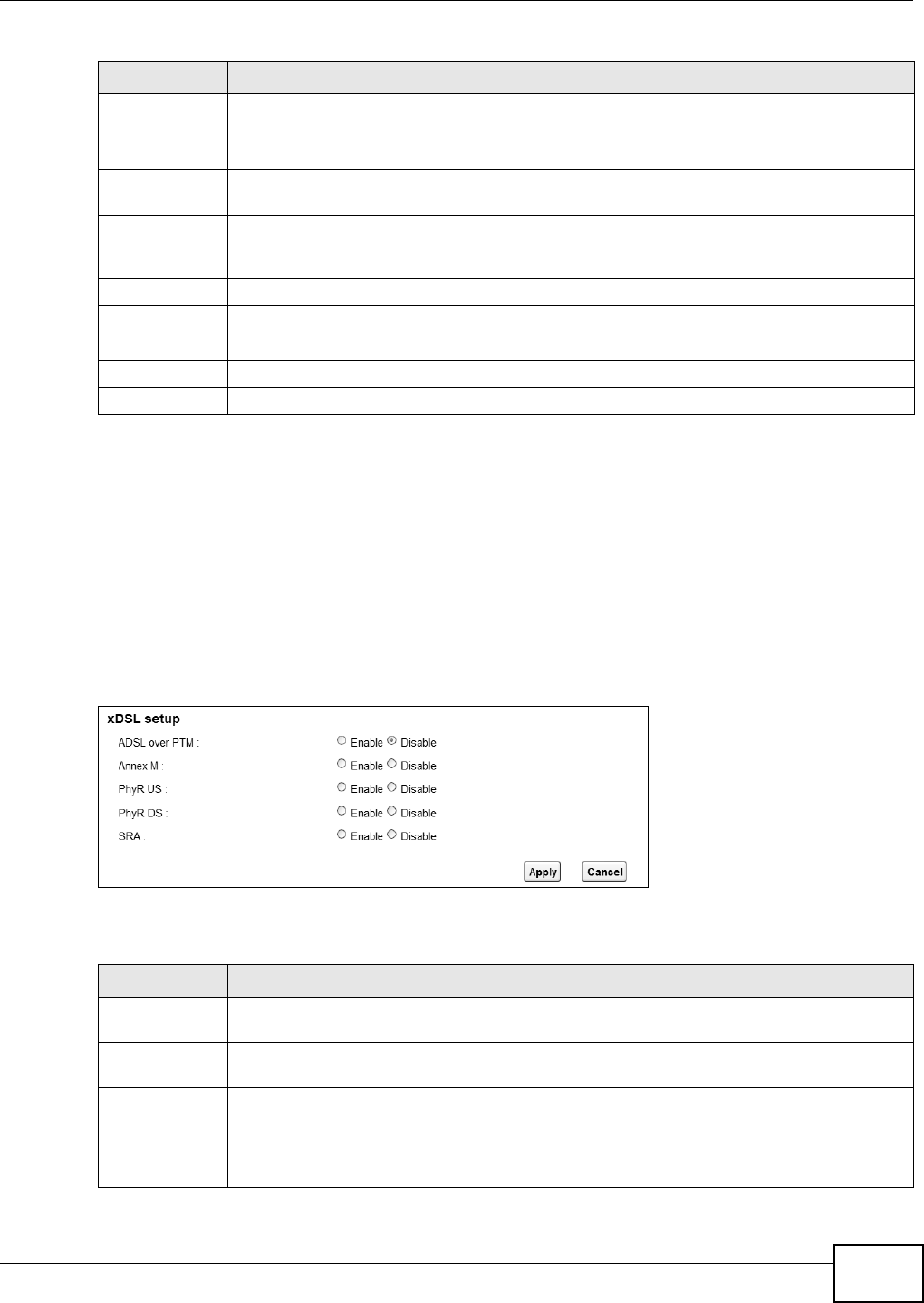
Chapter 5 Broadband
VMG8324-B10A / VMG8324-B30A Series User’s Guide 61
5.4 The Advanced Screen
Use t he Adva nced screen t o enable or disable ADSL over PTM, Annex M, DSL PhyR, and SRA
( Seam less Rat e Adaption) funct ions. The Device support s the PhyR retransm ission schem e. PhyR is
a ret ransm ission schem e designed t o prov ide prot ect ion against noise on t he DSL line. I t im proves
voice, video and data t ransm ission resilience by ut ilizing a retransm ission buffer.
Click N et w ork Se t t ing > Broa dband > Adva n ce d t o display t he following screen.
Figure 28 Net work Set t ing > Broadband > Advanced
The following t able describes t he labels in this screen.
Mail Ser ver Select a m ail server for the e- m ail address specified below.
I f you do not select a m ail server, e-m ail not ificat ions cannot be sent via e-m ail. You m ust
have configured a m ail server already in t he Main t e na n ce > Em ail N ot ifica t ion screen.
Over Budget
Em ail Tit le
Type a t it le t hat you want t o be in t he subject line of the e- m ail notificat ions t hat t he Device
sends.
Send
Notification t o
Em ail
Notificat ions are sent t o t he e- m ail address specified in t his field. I f t his field is left blank,
not ificat ions cannot be sent via e- m ail.
I nt erval Enter t he int erval of how m any m inut es y ou want the Device to e- m ail you.
Enable Log Select this to act ivate the logging funct ion at the int erval you set in this field.
Basic Click t his t o hide t he advanced settings of 3G backup.
Apply Click Apply t o save your changes back t o t he Device.
Cancel Click Ca nce l to ret urn to t he previous configurat ion.
Table 10 Net work Sett ing > Broadband > 3G Backup ( cont inued)
LABEL DESCRIPTION
Table 11 Net work Set t ing > Net work Set t ing > Broadband
LABEL DESCRIPTION
ADSL over PTM Select Ena ble t o use ADSL over PTM. Since PTM has less overhead than ATM, som e I SPs
use ADSL over PTM for bet t er perfor m ance.
Annex M You can enable Ann ex M for t he Device t o use double upst ream m ode to increase t he
m axim um upst ream t ransfer rat e.
PhyR US Enable or disable Ph yR US ( upst r eam ) for upst ream t ransm ission t o the WAN. PhyR US
should be enabled if dat a being transm itted upstream is sensitive to noise. However,
enabling PhyR US can decrease t he US line rat e. Enabling or disabling PhyR will require the
CPE to ret rain. For PhyR t o function, the DSLAM m ust also support PhyR and have it
enabled.
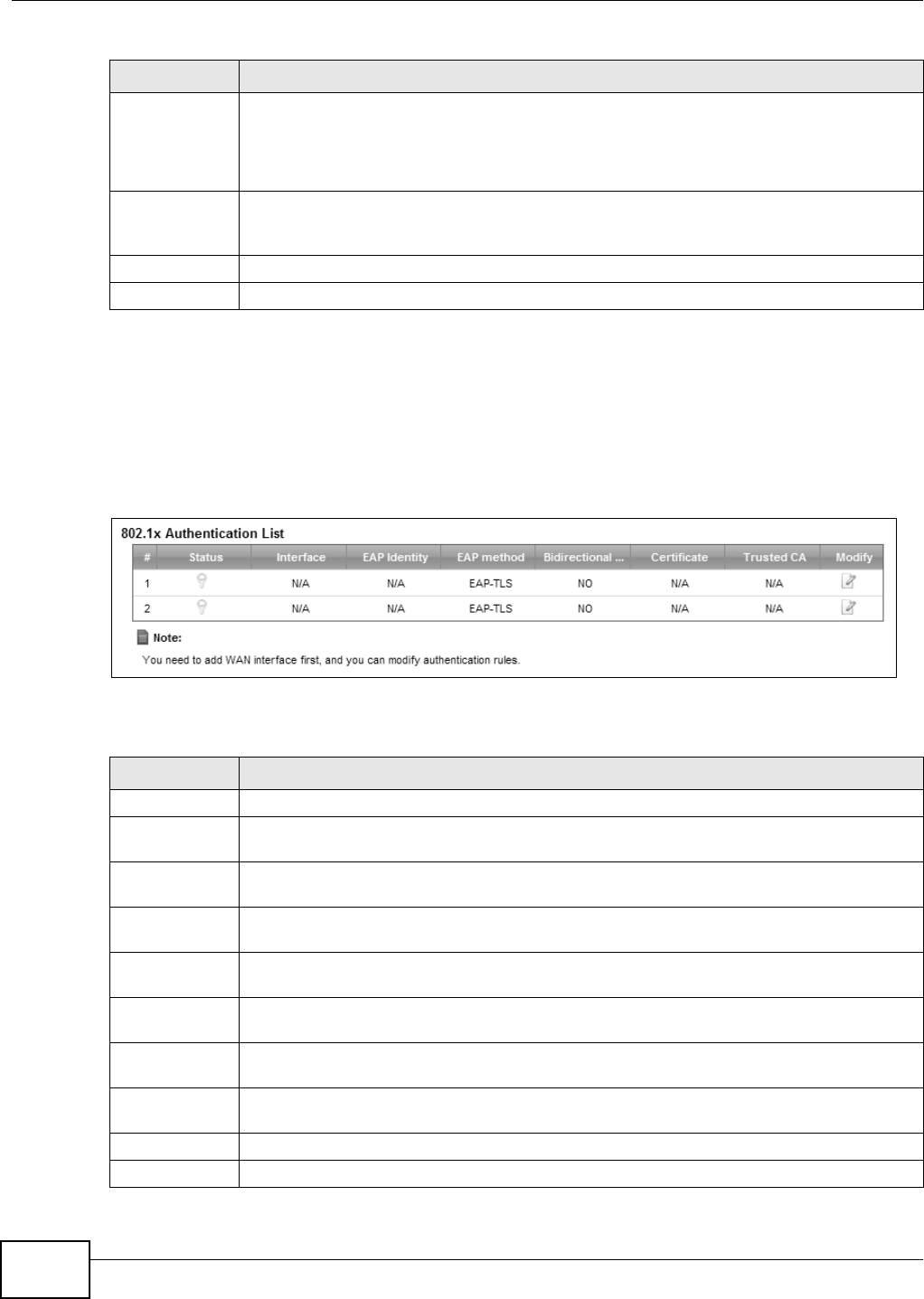
Chapter 5 Broadband
VMG8324-B10A / VMG8324-B30A Series User’s Guide
62
5.5 The 802.1x Screen
You can view and configure t he 802.1X aut hent icat ion set t ings in the 8 0 2 .1 x screen. Click
N e t w ork Se t t ing > Br oadba nd > 8 0 2 .1 x t o display t he following screen.
Figure 29 Net work Set t ing > Broadband > 802.1x
The following t able describes t he labels in this screen.
PhyR DS Enable or disable PhyR D S ( downst ream ) for downstream t ransm ission from the WAN.
PhyR DS should be enabled if data being transm itted downstream is sensit ive t o noise.
However, enabling PhyR DS can decrease t he DS line rate. Enabling or disabling PhyR w ill
require the CPE t o ret rain. For PhyR t o function, t he DSLAM m ust also suppor t PhyR and
have it enabled.
SRA Enable or disable Seam less Rat e Adaption (SRA) . Select En a ble t o have the Device
autom at ically adj ust t he connection’s dat a rat e accor ding t o line conditions wit hout
int errupting serv ice.
Apply Click Apply t o save your changes back t o t he Device.
Cancel Click Ca nce l to ret urn to t he previous configurat ion.
Table 11 Net work Set t ing > Net work Set t ing > Broadband ( cont inued)
LABEL DESCRIPTION
Table 12 Net work Sett ing > Net work Sett ing > 802.1x
LABEL DESCRIPTION
# This is the index num ber of t he ent r y.
St at us This field displays whet her t he authent icat ion is act ive or not. A yellow bulb signifies t hat
this aut henticat ion is active. A gray bulb signifies that this aut hent ication is not active.
I nterface This is the interface t hat uses the aut hent ication. This displays N / A when t here is no
int erface assigned.
EAP I dent it y This shows t he EAP ident ity of the authent icat ion. This displays N / A when t here is no EAP
ident it y assigned.
EAP m et hod This shows t he EAP m et hod used in t he authent icat ion. This displays N / A when t here is no
EAP m et hod assigned.
Bidir ect ional
Au t hen t icat ion
This shows w het her bidirect ional aut hent icat ion is allow ed.
Cert ificate This shows t he cert ificate used for t his authent icat ion. This displays N / A when ther e is no
cer t ificate assigned.
Trust ed CA This shows t he Trust ed CA used for this aut hent ication. This displays N / A when t here is no
Trust ed CA assigned.
Apply Click Apply t o save your changes back t o t he Device.
Cancel Click Ca nce l to ret urn to t he previous configurat ion.
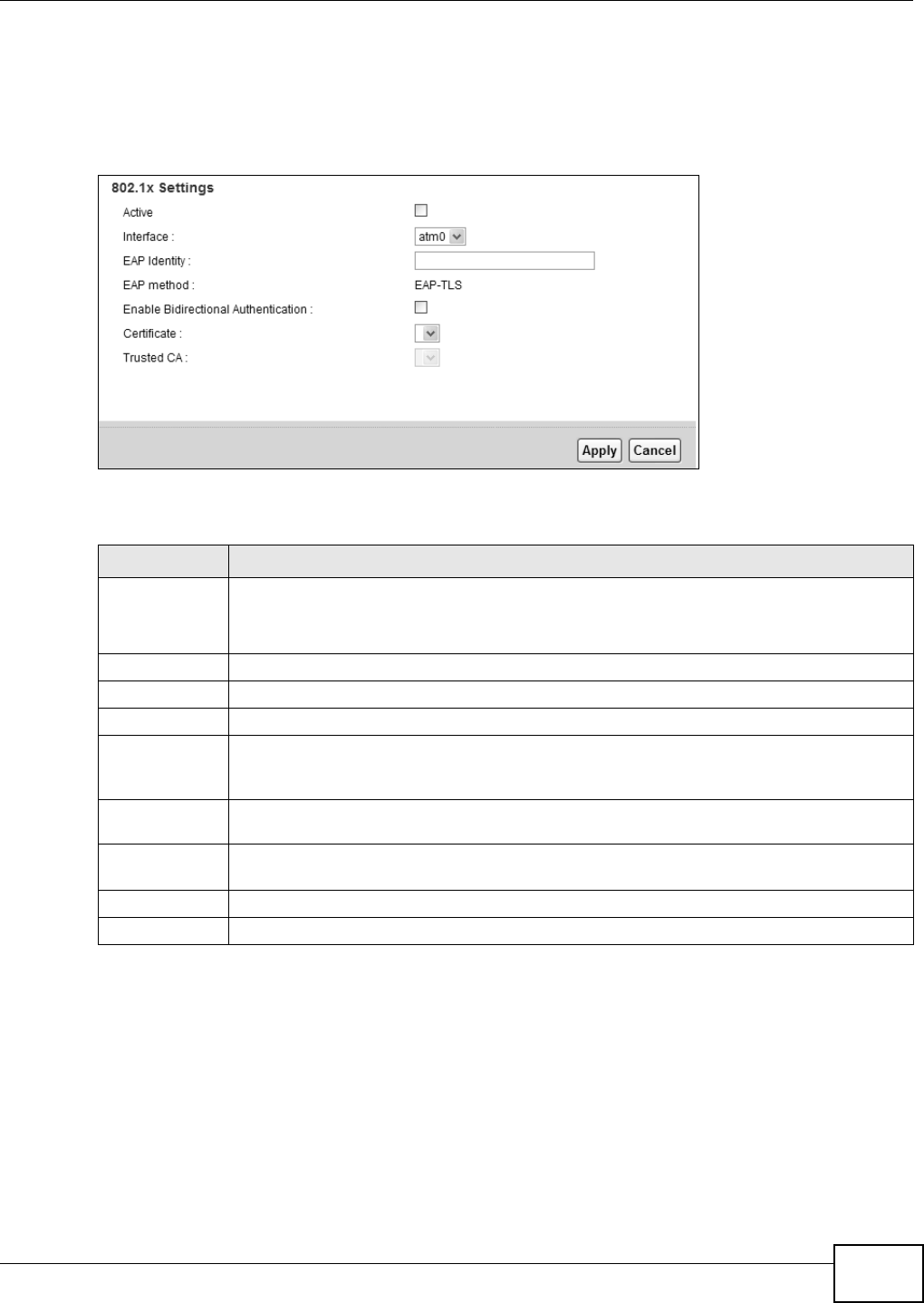
Chapter 5 Broadband
VMG8324-B10A / VMG8324-B30A Series User’s Guide 63
5.5.1 Edit 802.1X Settings
Use t his scr een t o edit 802.1X aut hentication set tings. Click t he Ed it icon next t o t he rule you want
to edit . The screen shown next appears.
Figure 30 Net work Set t ing > Broadband > 802.1x: Edit
The following t able describes t he labels in this screen.
5.6 The WAN Status Screen
Click N et w or k Set t ing > Broa dba nd > W a n Sta t u s to open this screen. Use this screen t o query
and view the hist orical t raffic t ransm ission rat e for a WAN interface in a bar chart. N / A displays if
the specified WAN int erface was disconnected at t hat t im e.
Table 13 Net work Sett ing > Broadband > 802.1x: Edit
LABEL DESCRIPTION
Act ive This field allows you t o act ivate/ deact ivat e t he authent icat ion.
Select this t o enable t he aut henticat ion. Clear this t o disable this aut hent ication w it hout
having to delete the ent ry.
I nterface Select an int erface to which t he authenticat ion applies.
EAP I dentity Ent er t he EAP ident it y of t he aut hent icat ion.
EAP m et hod This is t he EAP m et hod used for this authenticat ion.
Enable
Bidir ect ional
Au t hen t icat ion
Select this t o allow bidir ectional authent icat ion.
Cert ificate Select the cert ificate you want t o assign to t he authent icat ion. You need t o im port t he
cert ificat e in the Se cu r it y > Ce r t if ica t e s > Loca l Ce r t ifica t e s screen.
Trust ed CA Select the Trusted CA you want t o assign t o t he aut henticat ion. You need to im port the
cert ificat e in the Se cu r it y > Ce r t if ica t e s > Tru st e d CA screen.
Apply Click Apply t o save your changes.
Cancel Click Ca ncel t o exit this screen w ithout saving.
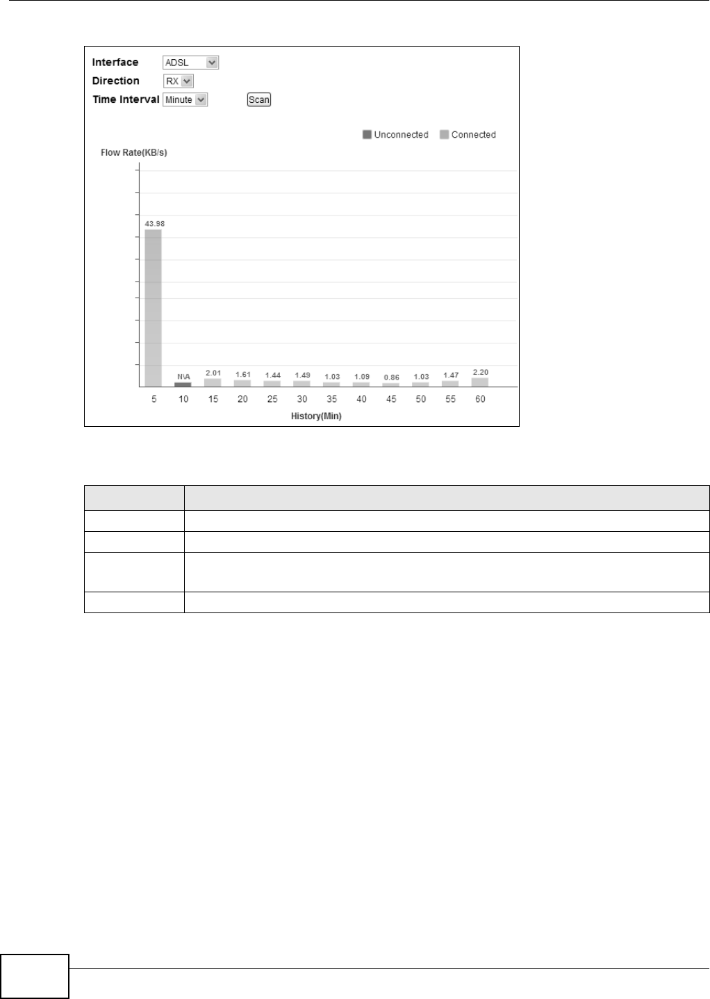
Chapter 5 Broadband
VMG8324-B10A / VMG8324-B30A Series User’s Guide
64
Figure 31 Net work Sett ing > Broadband > Wan St atus
The following t able describes t he labels in this screen.
5.7 Technical Reference
The following sect ion cont ains additional t echnical inform ation about the Device feat ures described
in this chapt er.
Encapsulation
Be sur e t o use t he encapsulat ion m et hod r equ ir ed by y ou r I SP. Th e Dev ice can w or k in br id g e m ode
or rout ing m ode. When t he Device is in rout ing m ode, it support s the following m et hods.
IP over Ethernet
I P over Ethernet ( I PoE) is an alt ernat ive t o PPPoE. I P packets are being delivered across an
Et hernet network, without using PPP encapsulation. They are routed between t he Ethernet int erface
Table 14 Net work Set t ing > Broadband > Wan St atus
LABEL DESCRIPTION
I nterface Select a WAN int erface t o see it s hist orical traffic t ransm ission rat e in the chart .
Dir ect ion Select RX or TX t o display received traffic only or t ransm it t ed t raffic only in the chart .
Tim e I nt erval Select the t im e periods t o display in t he chart . Available choices are M in ut e , D a y, and
Mon t h.
Scan Click this to updat e t he chart according t o your select ed crit er ia.

Chapter 5 Broadband
VMG8324-B10A / VMG8324-B30A Series User’s Guide 65
and t he WAN int erface and t hen form at t ed so t hat t hey can be under st ood in a bridged
environm ent . For inst ance, it encapsulat es rout ed Ethernet fram es into bridged Ethernet cells.
PPP over ATM (PPPoA)
PPPoA st ands for Point t o Point Protocol over ATM Adapt at ion Layer 5 ( AAL5) . A PPPoA connect ion
functions like a dial- up I nt ernet connect ion. The Device encapsulates t he PPP session based on
RFC1483 and sends it t hrough an ATM PVC ( Perm anent Vir t ual Circuit ) t o t he I nt ernet Service
Provider’s ( I SP) DSLAM (digit al access m ult iplexer) . Please r efer t o RFC 2364 for m ore inform at ion
on PPPoA. Refer t o RFC 1661 for m ore inform ation on PPP.
PPP over Ethernet (PPPoE)
Point- t o- Point Prot ocol over Ethernet ( PPPoE) provides access cont rol and billing functionality in a
m anner sim ilar t o dial- up services using PPP. PPPoE is an I ETF st andard ( RFC 2516) specifying how
a personal com put er ( PC) int eract s wit h a broadband m odem ( DSL, cable, w ireless, etc.)
connect ion.
For t he service provider, PPPoE offers an access and aut hent icat ion m et hod t hat works with exist ing
access cont rol system s ( for exam ple RADI US) .
One of t he benefits of PPPoE is t he abilit y to let you access one of m ult iple net work services, a
function known as dynam ic service select ion. This enables t he service prov ider to easily create and
offer new I P ser vices for individuals.
Operationally, PPPoE saves significant effort for both you and t he I SP or carrier, as it requires no
specific configurat ion of the broadband m odem at the cust om er site.
By im plem ent ing PPPoE direct ly on the Device ( rather t han individual com puters) , the com put ers on
the LAN do not need PPPoE software inst alled, since the Device does t hat part of t he task.
Furtherm ore, with NAT, all of t he LANs’ com put ers will have access.
RFC 1483
RFC 1483 describes t w o m et hods for Mult iprotocol Encapsulat ion over ATM Adapt at ion Layer 5
( AAL5). The first m et hod allows m ult iplexing of m ultiple protocols over a single ATM virt ual circuit
( LLC- based m ult iplexing) and t he second m et hod assum es t hat each protocol is car ried over a
separat e ATM virtual cir cuit ( VC-based m ult iplexing). Please refer t o RFC 1483 for m ore det ailed
inform at ion.
Multiplexing
There are two convent ions t o ident ify what protocols t he virtual circuit ( VC) is carrying. Be sure t o
use t he m ult iplexing m et hod required by your I SP.
VC- based Multiplexing
I n t his case, by prior m utual agreem ent , each prot ocol is assigned t o a specific virt ual circuit ; for
exam ple, VC1 carries I P, et c. VC-based m ultiplexing m ay be dom inant in environm ents where
dynam ic creat ion of large num bers of ATM VCs is fast and econom ical.
LLC- based Mult iplexing
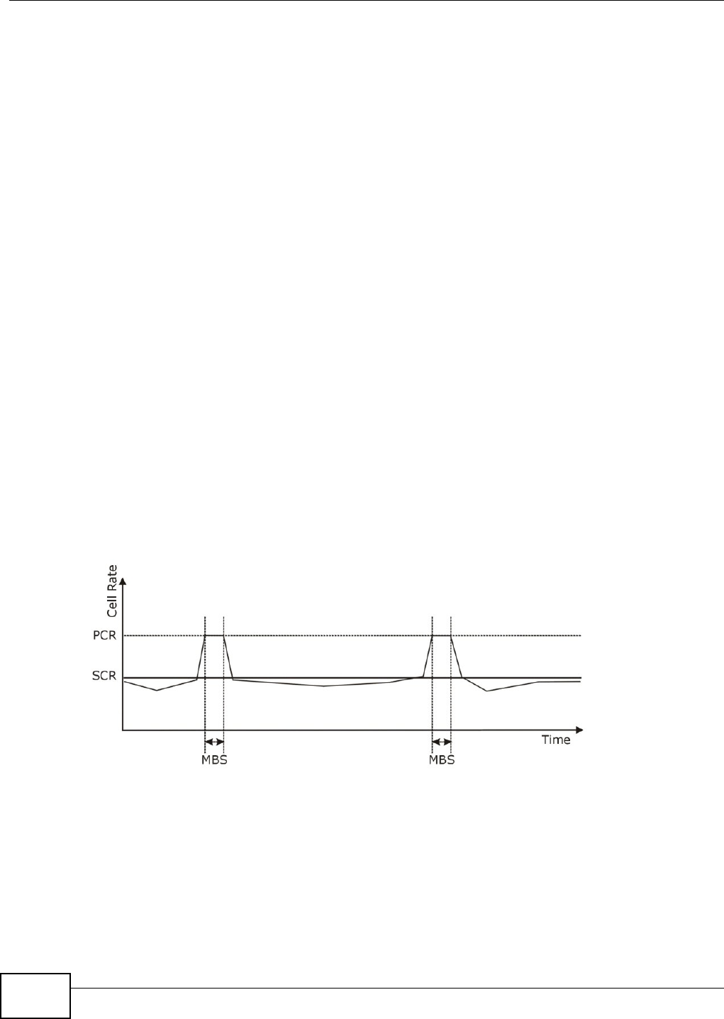
Chapter 5 Broadband
VMG8324-B10A / VMG8324-B30A Series User’s Guide
66
I n t his case one VC carries m ultiple protocols with prot ocol ident ifying inform ation being cont ained
in each packet header. Despit e t he ext ra bandwidth and processing overhead, t his m ethod m ay be
advantageous if it is not pract ical t o have a separate VC for each carried protocol, for exam ple, if
charging heavily depends on the num ber of sim ultaneous VCs.
Traffic Shaping
Traffic Shaping is an agreem ent bet w een t he carrier and t he subscriber t o regulate t he average rat e
and fluct uations of dat a t ransm ission over an ATM net work. This agr eem ent helps elim inat e
congestion, which is im port ant for transm ission of real tim e dat a such as audio and video
connect ions.
Peak Cell Rate ( PCR) is t he m axim um rat e at which t he sender can send cells. This param eter m ay
be lower ( but not higher) t han t he m axim um line speed. 1 ATM cell is 53 bytes ( 424 bit s) , so a
m axim um speed of 832Kbps gives a m axim um PCR of 1962 cells/ sec. This rate is not guarant eed
because it is dependent on t he line speed.
Sust ained Cell Rat e ( SCR) is t he m ean cell rat e of each burst y t raffic source. I t specifies the
m axim um average rat e at which cells can be sent over t he virt ual connect ion. SCR m ay not be
great er t han the PCR.
Maxim um Burst Size ( MBS) is t he m axim um num ber of cells t hat can be sent at t he PCR. Aft er MBS
is reached, cell rates fall below SCR unt il cell rat e averages to the SCR again. At t his t im e, m ore
cells ( up t o t he MBS) can be sent at t he PCR again.
I f t he PCR, SCR or MBS is set t o the default of "0" , t he syst em will assign a m axim um value t hat
corr elat es t o your upst ream line rate.
The following figure illust rat es t he relationship between PCR, SCR and MBS.
Figure 32 Exam ple of Traffic Shaping
ATM Traffic Classes
These are the basic ATM t raffic classes defined by t he ATM Forum Traffic Managem ent 4.0
Specificat ion.
Const ant Bit Rat e (CBR)
Const ant Bit Rat e ( CBR) provides fixed bandwidt h t hat is always available even if no dat a is being
sent. CBR t raffic is generally t im e- sensitive ( doesn't t olerate delay) . CBR is used for connections

Chapter 5 Broadband
VMG8324-B10A / VMG8324-B30A Series User’s Guide 67
that cont inuously r equire a specific am ount of bandwidt h. A PCR is specified and if t raffic exceeds
this rat e, cells m ay be dropped. Exam ples of connect ions t hat need CBR would be high- resolut ion
video and voice.
Variable Bit Rat e ( VBR)
The Variable Bit Rat e (VBR) ATM t raffic class is used wit h bursty connect ions. Connections t hat use
the Variable Bit Rat e ( VBR) traffic class can be grouped into real tim e ( VBR- RT) or non-real t im e
( VBR- nRT) connect ions.
The VBR- RT ( real- t im e Variable Bit Rat e) t ype is used with bursty connect ions t hat require closely
cont rolled delay and delay variat ion. I t also provides a fixed am ount of bandwidth ( a PCR is
specified) but is only available when dat a is being sent . An exam ple of an VBR- RT connect ion would
be video conferencing. Video conferencing requires real-t im e dat a transfers and t he bandwidt h
requirem ent varies in proport ion to the video im age's changing dynam ics.
The VBR- nRT ( non real-t im e Variable Bit Rat e) type is used with bursty connect ions t hat do not
require closely controlled delay and delay variat ion. I t is com m only used for " burst y" t raffic t ypical
on LANs. PCR and MBS define t he burst levels, SCR defines the m inim um level. An exam ple of an
VBR- nRT connect ion would be non-t im e sensit ive data file t ransfers.
Unspecified Bit Rat e ( UBR)
The Unspecified Bit Rat e ( UBR) ATM t raffic class is for bursty dat a t ransfers. However, UBR doesn't
guarant ee any bandwidth and only deliver s t raffic w hen t he net work has spare bandwidth. An
exam ple applicat ion is background file transfer.
IP Address Assignment
A st atic I P is a fixed I P t hat your I SP gives you. A dynam ic I P is not fixed; t he I SP assigns you a
different one each t im e. The Single User Account feature can be enabled or disabled if you have
eit her a dynam ic or st at ic I P. However t he encapsulat ion m et hod assigned influences your choices
for I P address and default gateway.
Introduction to VLANs
A Virt ual Local Area Network ( VLAN) allows a physical network t o be part it ioned int o m ultiple logical
net works. Devices on a logical net work belong to one gr oup. A device can belong t o m ore t han one
group. Wit h VLAN, a device cannot direct ly t alk t o or hear from devices t hat are not in the sam e
group( s) ; t he t raffic m ust first go t hrough a router.
I n Multi-Tenant Unit ( MTU) applications, VLAN is vit al in providing isolation and security am ong t he
subscribers. When properly configured, VLAN prevents one subscriber from accessing the net w ork
resources of another on t he sam e LAN, t hus a user w ill not see t he print ers and hard disks of
another user in t he sam e building.
VLAN also increases net work perform ance by lim it ing broadcast s t o a sm aller and m ore
m anageable logical broadcast dom ain. I n t raditional swit ched environm ents, all broadcast packets
go t o each and every individual port . With VLAN, all broadcast s ar e confined t o a specific broadcast
dom ain.

Chapter 5 Broadband
VMG8324-B10A / VMG8324-B30A Series User’s Guide
68
Introduction to IEEE 802.1Q Tagged VLAN
A tagged VLAN uses an explicit t ag ( VLAN I D) in the MAC header to identify the VLAN m em bership
of a fram e across bridges - t hey ar e not confined t o t he switch on which t hey were created. The
VLANs can be creat ed st at ically by hand or dynam ically t hrough GVRP. The VLAN I D associat es a
fram e wit h a specific VLAN and provides t he inform at ion t hat switches need to process the fram e
across t he net work. A t agged fram e is four byt es longer t han an unt agged fram e and cont ains t wo
byt es of TPI D ( Tag Prot ocol I dent ifier) , residing wit hin the type/ lengt h field of t he Ethernet fram e)
and t wo byt es of TCI ( Tag Control I nform ation) , st art s aft er t he source address field of t he Ethernet
fram e) .
The CFI ( Canonical Form at I ndicat or) is a single-bit flag, always set t o zero for Ethernet sw itches. I f
a fram e received at an Ether net port has a CFI set to 1, t hen t hat fram e should not be forwarded as
it is t o an unt agged por t . The r em aining twelve bit s define t he VLAN I D, giving a possible m axim um
num ber of 4,096 VLANs. Not e that user priorit y and VLAN I D are independent of each ot her. A
fram e wit h VI D (VLAN I dent ifier) of null (0) is called a priority fram e, m eaning t hat only t he priorit y
level is significant and the default VI D of t he ingress port is given as t he VI D of t he fram e. Of the
4096 possible VI Ds, a VI D of 0 is used to identify priorit y fram es and value 4095 ( FFF) is reserved,
so t he m axim um possible VLAN configurat ions are 4,094.
Multicast
I P packet s are t ransm it t ed in either one of two ways - Unicast ( 1 sender - 1 recipient) or Broadcast
( 1 sender - everybody on t he net work) . Multicast delivers I P packet s t o a group of host s on t he
net work - not everybody and not j ust 1.
I nt ernet Group Mult icast Prot ocol ( I GMP) is a net w ork- layer protocol used t o est ablish m em bership
in a Mult icast group - it is not used t o carry user dat a. I GMP version 2 ( RFC 2236) is an
im provem ent over version 1 ( RFC 1112) but I GMP version 1 is st ill in wide use. I f you would like t o
read m ore det ailed inform at ion about interoperability bet w een I GMP ver sion 2 and version 1, please
see sect ions 4 and 5 of RFC 2236. The class D I P address is used t o identify host groups and can be
in the range 224.0.0.0 to 239.255.255.255. The address 224.0.0.0 is not assigned t o any group
and is used by I P m ult icast com put ers. The address 224.0.0.1 is used for query m essages and is
assigned t o t he perm anent group of all I P host s ( including gat eways) . All host s m ust j oin the
224.0.0.1 group in order t o part icipat e in I GMP. The address 224.0.0.2 is assigned t o t he m ult icast
rout ers group.
At st art up, t he Device queries all direct ly connected net works t o gat her group m em bership. Aft er
that, the Device periodically updat es t his inform at ion.
DNS Server Address Assignment
Use Dom ain Nam e Syst em (DNS) to m ap a dom ain nam e t o its corr esponding I P address and vice
versa, for inst ance, t he I P address of www.zyxel.com is 204.217.0.2. The DNS server is ext rem ely
im portant because without it , you m ust know the I P addr ess of a com put er before you can access
it .
The Device can get the DNS server addresses in t he following ways.
TPI D
2 Byt es
User Priority
3 Bit s
CFI
1 Bit
VLAN I D
12 Bit s

Chapter 5 Broadband
VMG8324-B10A / VMG8324-B30A Series User’s Guide 69
1The I SP tells you the DNS server addresses, usually in t he form of an inform ation sheet, when you
sign up. I f your I SP gives you DNS server addresses, m anually enter t hem in the DNS server fields.
2I f your I SP dynam ically assigns t he DNS server I P addresses ( along with t he Device’s WAN I P
address) , set t he DNS server fields t o get t he DNS server address from t he I SP.
IPv6 Addressing
The 128-bit I Pv6 address is writt en as eight 16- bit hexadecim al blocks separat ed by colons ( : ) . This
is an exam ple I Pv6 address 2001:0db8:1a2b:0015:0000:0000:1a2f:0000.
I Pv6 addresses can be abbreviat ed in two ways:
• Leading zeros in a block can be om itt ed. So 2001:0db8:1a2b:0015:0000:0000:1a2f:0000 can
be writ t en as 2001:db8:1a2b:15:0:0:1a2f:0.
• Any num ber of consecut ive blocks of zeros can be replaced by a double colon. A double colon can
only appear once in an I Pv6 address. So 2001:0db8:0000:0000:1a2f:0000:0000:0015 can be
wr itt en as 2001:0db8::1a2f:0000:0000:0015, 2001:0db8:0000:0000:1a2f::0015,
2001:db8::1a2f:0:0:15 or 2001:db8:0:0:1a2f::15.
IPv6 Prefix and Prefix Length
Sim ilar t o an I Pv4 subnet m ask, I Pv6 uses an addr ess prefix to represent t he network address. An
I Pv6 prefix length specifies how m any m ost significant bits ( st art from the left) in t he address
com pose t he net w ork address. The prefix lengt h is writ t en as “ / x” where x is a num ber. For
exam ple,
2001:db8:1a2b:15::1a2f:0/32
m eans t hat t he first 32 bits (2001:db8) is the subnet prefix.

Chapter 5 Broadband
VMG8324-B10A / VMG8324-B30A Series User’s Guide
70

VMG8324-B10A / VMG8324-B30A Series User’s Guide 71
CHAPTER 6
Wireless
6.1 Overview
This chapt er describes t he Device’s N e t w or k Se t t ing > W ire le ss scr eens. Use these screens t o
set up your Device’s wireless connect ion.
6.1.1 What You Can Do in this Chapter
This sect ion describes t he Device’s W ir e less screens. Use t hese screens t o set up your Device’s
wireless connection.
• Use the Ge n e r a l screen to enable t he Wireless LAN, enter t he SSI D and select t he wireless
security m ode (Sect ion 6.2 on page 72) .
• Use the M ore AP screen t o set up m ult iple wireless net works on your Device (Sect ion 6.3 on
page 81) .
• Use the M AC Aut hent icat ion screen t o allow or deny wireless clients based on t heir MAC
addresses from connect ing t o t he Device ( Sect ion 6.4 on page 85) .
• Use the W PS screen t o enable or disable WPS, view or generate a security PI N (Personal
I dent ificat ion Num ber ) ( Sect ion 6.5 on page 86) .
• Use the W M M screen to enable Wi- Fi MultiMedia ( WMM) t o ensure qualit y of service in wireless
net works for m ult im edia applicat ions (Sect ion 6.6 on page 87) .
• Use the W D S screen to set up a Wireless Dist ribut ion Syst em , in which t he Device act s as a
bridge wit h other ZyXEL access point s (Sect ion 6.7 on page 88) .
• Use the Ot hers screen to configure wireless advanced feat ures, such as t he RTS/ CTS Threshold
(Sect ion 6.8 on page 90) .
• Use the Cha nnel Sta t us screen to scan wireless LAN channel noises and view t he result s
(Sect ion 6.9 on page 92) .

Chapter 6 Wireless
VMG8324-B10A / VMG8324-B30A Series User’s Guide
72
6.1.2 What You Need to Know
Wireless Basics
“ Wireless” is essent ially radio com m unication. I n t he sam e way that walkie- t alkie radios send and
receive inform ation over t he airwaves, w ireless net working devices exchange inform at ion w ith one
another. A w ireless net working device is j ust like a radio that let s your com put er exchange
inform ation with radios att ached t o ot her com put ers. Like walkie-t alkies, m ost wireless networking
devices operat e at radio frequency bands t hat are open t o t he public and do not require a license t o
use. However, w ireless net working is different from t hat of m ost t radit ional radio com m unicat ions in
that t here a num ber of wireless net working st andards available with different m ethods of dat a
encrypt ion.
Finding Out More
See Sect ion 6.10 on page 92 for advanced t echnical inform ation on wir eless net w orks.
6.2 The General Screen
Use t his screen to enable t he Wireless LAN, ent er t he SSI D and select t he wir eless security m ode.
Note: I f you are configur ing the Device from a com put er connect ed to t he wireless LAN
and you change t he Device’s SSI D, channel or security set t ings, you will lose your
wireless connect ion when you press Apply to confirm . You m ust then change t he
wireless sett ings of your com put er t o m atch t he Device’s new sett ings.
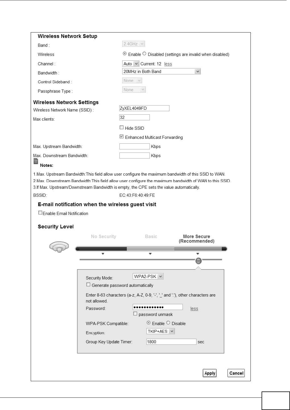
Chapter 6 Wireless
VMG8324-B10A / VMG8324-B30A Series User’s Guide 73
Click N e t w o rk Set t ing > W ir e less t o open the Ge ne r a l screen.
Figure 33 Net work Set t ing > Wireless > General

Chapter 6 Wireless
VMG8324-B10A / VMG8324-B30A Series User’s Guide
74
The following t able describes t he general wir eless LAN labels in t his screen.
Table 15 Net work Sett ing > Wireless > General
LABEL DESCRIPTION
Wireless Netw ork Set up
Wireless You can Ena ble or D isa ble the wireless LAN in this field.
Band This show s t he w ir eless band w hich t his radio pr ofile is using. 2 .4 GH z is t he frequency used
by I EEE 802.11b/ g/ n wireless client s.
Channel Use Au t o to have t he Device autom at ically det erm ine a channel t o use.
m ore. ../ less Click m or e ... t o show m ore inform at ion. Click le ss t o hide t hem .
Bandwidt h Select w het her t he Device uses a wir eless channel widt h of 2 0 M H z or 4 0 M Hz.
A standard 20MHz channel offers transfer speeds of up t o 150Mbps whereas a 40MHz
channel uses two st andard channels and offers speeds of up t o 300 Mbps.
40MHz ( channel bonding or dual channel) bonds t wo adj acent radio channels t o incr ease
t hroughput . The wireless client s m ust also support 40 MHz. I t is oft en bet t er t o use the 20
MHz set t ing in a locat ion where t he environm ent hinders t he wireless signal.
Select 2 0 M H z if you want to lessen radio interference with other wireless devices in your
neighborhood or the wireless client s do not support channel bonding.
Cont rol
Sideband
This is available for som e regions when you select a specific channel and set the Bandwidt h
field t o 4 0 M Hz . Set whether t he cont r ol channel ( set in the Ch a nne l field) should be in t he
Low e r or Uppe r range of channel bands.
Passphrase
Ty p e
I f you set securit y for the wir eless LAN and have the Device generat e a passw ord, the
set t ing in this field determ ines how the Device generat es the password.
Select N one t o set t he Device’s password generat ion to not be based on a passphrase.
Select Fixe d to use a 16 charact er passphrase for generat ing a passwor d.
Select Va r ia ble t o use a 16 to 63 charact er passphrase for generating a password.
Passphrase Key For a fixed type passphrase ent er 16 alphanum eric characters ( 0- 9, A-Z, w it h no spaces) . I t
m ust cont ain bot h let t ers and num bers and is case- sensit ive.
For a variable t ype passphrase ent er 16 to 63 alphanum er ic charact ers ( 0- 9, A-Z, wit h no
spaces) . I t m ust cont ain both let t ers and num bers and is case- sensitive.
Wireless Netw ork Set t ings
Wireless
Net work Nam e
( SSI D)
The SSI D ( Service Set I Dent it y) identifies t he service set wit h which a wireless device is
associat ed. Wireless devices associat ing t o t he access point ( AP) m ust have t he sam e SSI D.
Ent er a descr ipt ive nam e (up to 32 English keyboard charact ers) for the wir eless LAN.
Max client s Specify t he m axim um num ber of client s t hat can connect to this net work at t he sam e t im e.
Hide SSI D Select t his check box t o hide t he SSI D in t he out going beacon fram e so a st at ion cannot
obt ain the SSI D t hr ough scanning using a site survey t ool.
Enhanced
Mult icast
Forwarding
Select this check box t o allow t he Device t o convert wireless m ult icast traffic int o wireless
unicast t raffic.
Maxim um
Upst ream
Bandwidt h
Specify the m axim um rat e for upst ream wireless t raffic to t he WAN from this WLAN in
kilobit s per second ( Kbps).
Maxim um
Dow nst ream
Bandwidt h
Specify the m axim um rat e for dow nst r eam wireless traffic t o t his WLAN from t he WAN in
kilobit s per second ( Kbps) .
BSSI D This shows the MAC address of t he wireless int erface on t he Dev ice when wireless LAN is
enabled.
Security Level
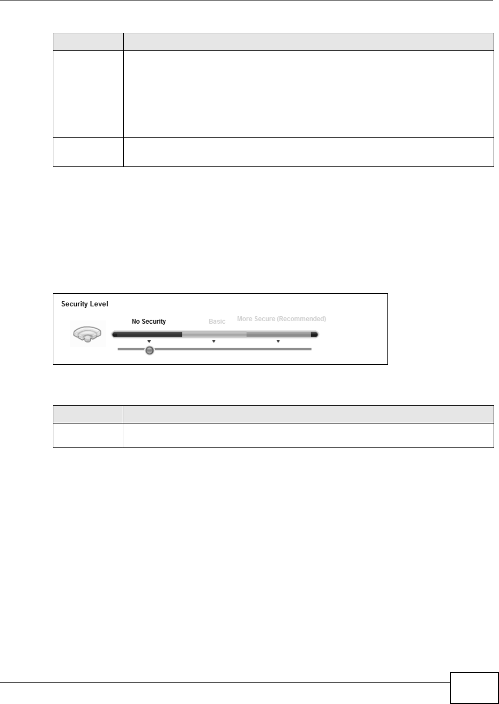
Chapter 6 Wireless
VMG8324-B10A / VMG8324-B30A Series User’s Guide 75
6.2.1 No Security
Select N o Se curity t o allow wireless st at ions to com m unicat e with t he access points wit hout any
dat a encrypt ion or authentication.
Note: I f you do not enable any w ireless securit y on your Dev ice, your net w ork is
accessible t o any wireless networking device t hat is within range.
Figure 34 Wireless > General: No Securit y
The following t able describes t he labels in this screen.
6.2.2 Basic (WEP Encryption)
WEP encrypt ion scram bles t he data t ransm it t ed between the wireless st at ions and the access point s
( AP) to keep net work com m unications privat e. Bot h t he wireless st ations and the access point s
m ust use the sam e WEP key.
Not e: WEP is ext rem ely insecure. I t s encryption can be broken by an at tacker, using
widely-available soft ware. I t is strongly recom m ended that you use a m ore
effective securit y m echanism . Use the strongest securit y m echanism t hat all the
wireless devices in your netw ork support . For exam ple, use WPA-PSK or WPA2- PSK
if all your wireless devices support it , or use WPA or WPA2 if your wireless devices
support it and you have a RADI US server. I f your wireless devices support nothing
st ronger t han WEP, use t he highest encrypt ion level available.
Your Device allows you t o configure up t o four 64- bit or 128- bit WEP keys but only one key can be
enabled at any one t im e.
Security Mode Select Ba sic ( W EP, 8 0 2 .1 X) or M or e Se cur e ( W PA( 2 ) - PSK, W PA( 2 ) ) t o add security
on this wir eless net w ork. The wireless client s which want t o associat e t o t his net work m ust
have sam e wireless securit y set t ings as the Device. When y ou select t o use a security,
addit ional opt ions appears in t his screen.
Or you can select N o Securit y t o allow any client t o associate this net work wit hout any dat a
encryption or aut hent icat ion.
See t he follow ing sect ions for m ore details about t his field.
Apply Click Apply t o save y our changes.
Cancel Click Ca ncel t o rest ore your previously saved set t ings.
Table 15 Net work Sett ing > Wireless > General ( continued)
LABEL DESCRIPTION
Table 16 Wireless > General: No Securit y
LABEL DESCRIPTION
Security Level Choose N o Secu rit y t o allow all wir eless connect ions wit hout data encrypt ion or
au then t icat ion .
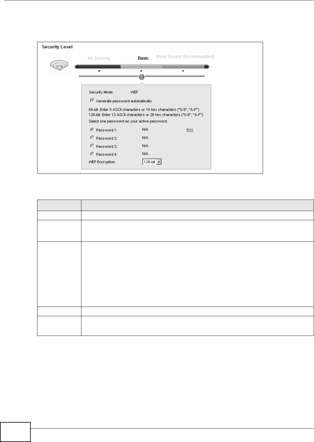
Chapter 6 Wireless
VMG8324-B10A / VMG8324-B30A Series User’s Guide
76
I n order to configure and enable WEP encryption, click N e t w or k Se t t in g > W ir e le ss t o display t he
Gene r al screen, t hen select Ba sic as the security level.
Figure 35 Wireless > General: Basic (WEP)
The following t able describes t he labels in this screen.
6.2.3 Basic (802.1X)
Use t his scr een t o configure 802.1X encrypt ion and aut hent icat ion. Configure your RADI US server
inform ation and WEP encrypt ion set t ings. Use t his security m et hod if your wireless usernam es and
passwords are configur ed on a RADI US server.
Table 17 Wireless > General: Basic ( WEP)
LABEL DESCRIPTION
Security Level Select Ba sic to enable WEP dat a encryption.
Generat e
password
autom at ically
Select this opt ion t o have t he Dev ice autom at ically generat e a passw ord. The password field
will not be configurable when you select t his opt ion.
Passw ord 1 ~ 4 The password ( WEP keys) ar e used to encrypt dat a. Both the Device and the wireless
st ations m ust use t he sam e passw ord ( WEP key) for dat a t ransm ission.
I f you chose 6 4 - bit WEP, t hen ent er any 5 ASCII characters or 10 hexadecim al characters
( "0-9", " A- F").
I f you chose 1 2 8 - bit WEP, t hen enter 13 ASCII character s or 26 hexadecim al charact ers
( "0-9", " A-F").
You m ust configure at least one password, only one password can be act ivat ed at any one
tim e.
m ore. ../ less Click m ore ... t o show m or e fields in this section. Click less t o hide t hem .
WEP Encry ption Select 6 4 - b it s or 1 2 8 - b it s.
This dictat es t he length of the security key t hat the net w ork is going t o use.
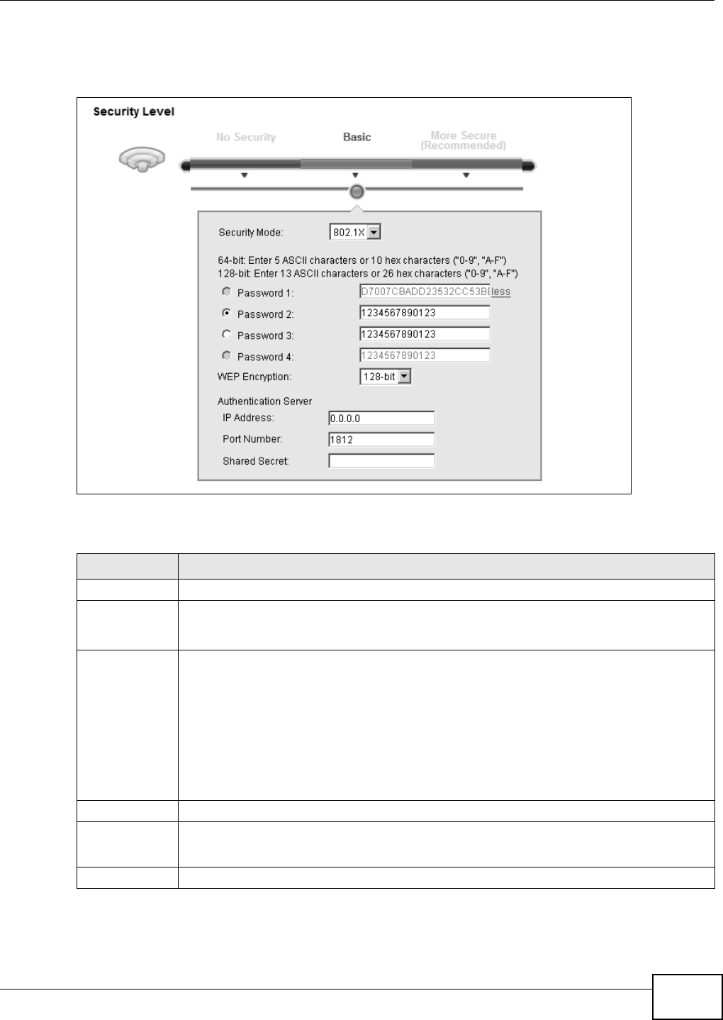
Chapter 6 Wireless
VMG8324-B10A / VMG8324-B30A Series User’s Guide 77
I n order to configure and enable WEP encryption, click N e t w or k Se t t in g > W ir e le ss t o display t he
Gene r al screen, t hen select Ba sic as the security level and 8 0 2 .1 X as the Security Mode .
Figure 36 Wireless > General: Basic (802.1X)
The following t able describes t he labels in this screen.
Table 18 Wireless > General: Basic ( 802.1X)
LABEL DESCRIPTION
Security Level Select Ba sic and 8 0 2 .1 X t o enable 802.1X data encr ypt ion.
Generat e
password
autom at ically
Select this opt ion t o have t he Dev ice autom at ically generat e a passw ord. The password field
will not be configurable when you select t his opt ion.
Passw ord 1 ~ 4 The password (WEP key) is used to encrypt data. Both t he Device and t he w ireless st at ions
m ust use t he sam e password (WEP key ) for dat a t ransm ission.
I f you chose 6 4 - bit WEP, t hen ent er any 5 ASCII characters or 10 hexadecim al characters
( "0-9", " A- F").
I f you chose 1 2 8 - bit WEP, t hen enter 13 ASCII character s or 26 hexadecim al charact ers
( "0-9", " A-F").
You m ust configure at least one password, only one password can be act ivat ed at any one
tim e.
m ore. ../ less Click m ore ... t o show m or e fields in this section. Click less t o hide t hem .
WEP Encry ption Select 6 4 - b it s or 1 2 8 - b it s.
This dictat es t he length of the security key t hat the net w ork is going t o use.
I P Address Enter t he I P address of an external RADI US server in dotted decim al notation.

Chapter 6 Wireless
VMG8324-B10A / VMG8324-B30A Series User’s Guide
78
Port Num ber The default port of a RADI US server for authent icat ion is 1812. You need not change t his
value unless your net work adm inist rator instruct s you t o do so.
Shared Secret Specify a password ( up to 32 alphanum eric charact ers) as the key to be shared bet ween t he
ext ernal RADI US server and t he Device. This key is not sent over the networ k. This key
m ust be t he sam e on t he ext er nal RADI US ser ver and t he Device.
Table 18 Wireless > General: Basic ( 802.1X) ( cont inued)
LABEL DESCRIPTION
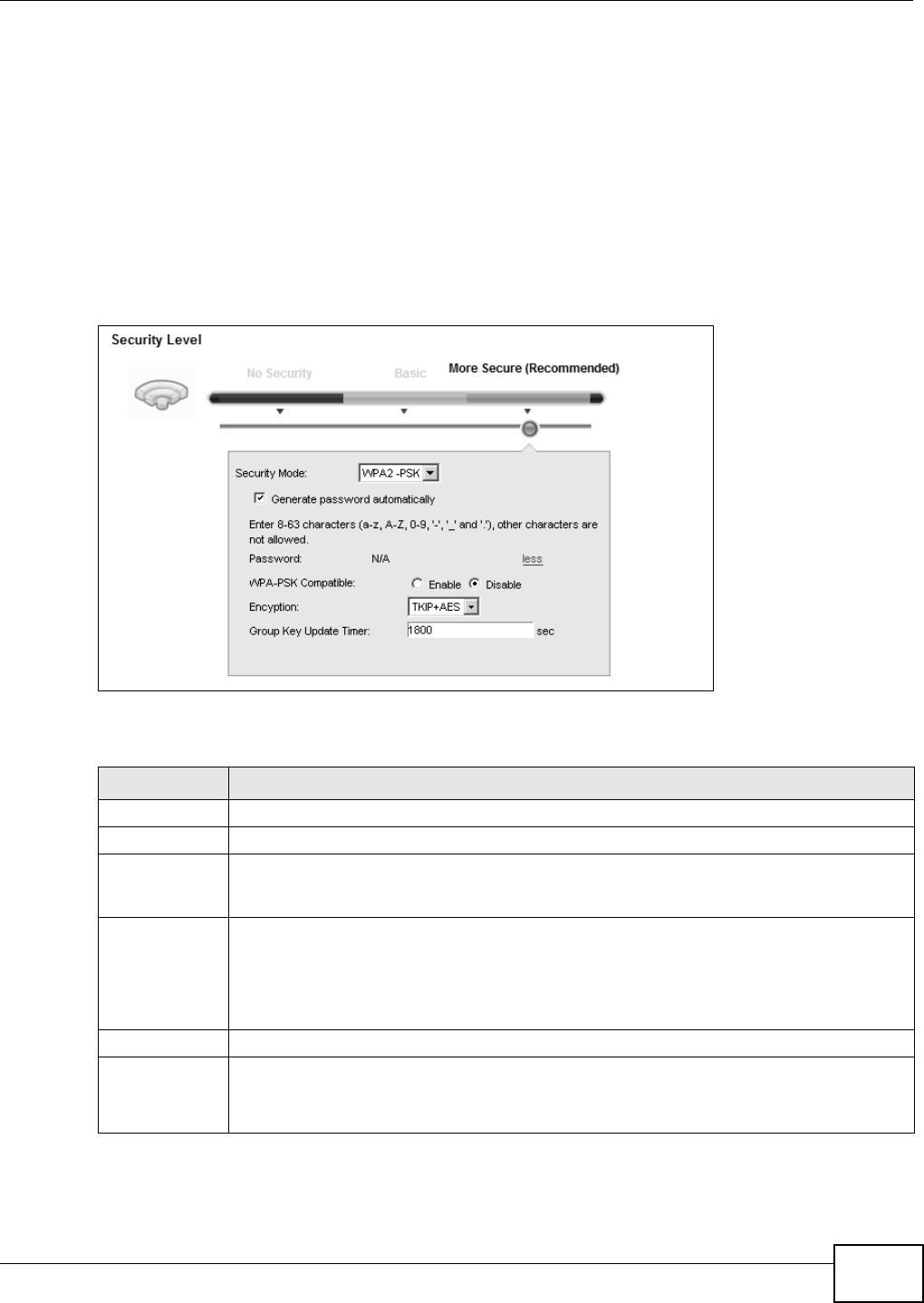
Chapter 6 Wireless
VMG8324-B10A / VMG8324-B30A Series User’s Guide 79
6.2.4 More Secure (WPA(2)-PSK)
The WPA- PSK security m ode provides bot h im proved data encryption and user aut hent icat ion over
WEP. Using a Pre- Shared Key ( PSK), bot h t he Device and t he connecting client share a com m on
password in order to validate t he connect ion. This t ype of encryption, while r obust , is not as st rong
as WPA, WPA2 or ev en WPA2 - PSK. Th e WPA2 - PSK secur it y m ode is a n ew er, m or e r obust ver sion of
the WPA encryption st andard. I t offers slightly bett er security, alt hough the use of PSK m akes it
less robust than it could be.
Click N et w ork Se t t ing > W ireless t o display t he Ge ne r a l screen. Select M or e Secure as t he
security level. Then select W PA- PSK or W PA2 - PSK from t he Se cu r ity M ode list .
Figure 37 Wireless > General: More Secure: WPA( 2) - PSK
The following t able describes t he labels in this screen.
Table 19 Wireless > General: Mor e Secure: WPA( 2) - PSK
LABEL DESCRIPTION
Security Level Select M ore Secu r e to enable WPA( 2) - PSK data encrypt ion.
Security Mode Select W PA- PSK or W PA2 - PSK from t he drop- down list box.
Generat e
password
autom at ically
Select t his option t o have t he Device autom at ically generate a password. The passwor d field
will not be configurable when you select this opt ion.
Passw ord The encryption m echanism s used for WPA( 2) and WPA( 2)- PSK are t he sam e. The only
differ ence bet ween t he two is t hat WPA( 2) - PSK uses a sim ple com m on passwor d, instead of
user- specific credent ials.
I f you did not select Gene rat e passw or d a ut om a t ically, you can m anually type a pre-
shared key from 8 t o 64 case- sensit ive keyboard charact ers.
m ore. ../ less Click m ore ... t o show m ore fields in t his sect ion. Click le ss t o hide t hem .
WPA-PSK
Com pat ible
This field appears when you choose W PA- PSK2 as the Secu rit y Mode .
Check this field to allow wireless devices using W PA- PSK securit y m ode t o connect t o your
Device. The Device support s WPA- PSK and WPA2- PSK sim ultaneously.
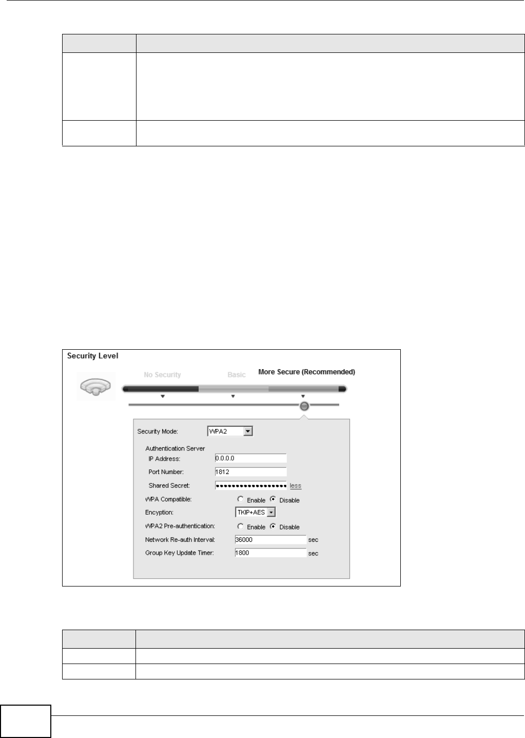
Chapter 6 Wireless
VMG8324-B10A / VMG8324-B30A Series User’s Guide
80
6.2.5 WPA(2) Authentication
The WPA2 securit y m ode is current ly the m ost robust form of encrypt ion for wireless net works. I t
requires a RADI US server t o aut hent icat e user credent ials and is a full im plem ent at ion t he securit y
protocol. Use t his securit y opt ion for m axim um prot ection of your net w ork. However, it is t he least
backwards com pat ible with older devices.
The WPA securit y m ode is a securit y subset of WPA2. I t requires the presence of a RADI US server
on your net work in order t o validat e user credentials. This encrypt ion standard is slight ly older t han
WPA2 and t herefore is m ore com pat ible wit h older devices.
Click N et w ork Se t t ing > W ireless t o display t he Ge ne r a l screen. Select M or e Secure as t he
security level. Then select W PA or W PA2 from the Secur it y Mode list.
Figure 38 Wireless > General: More Secure: WPA( 2)
The following t able describes t he labels in this screen.
Encrypt ion Select t he encrypt ion type ( TKI P, AES or TKI P+ AES) for dat a encryption.
Select TKI P if your wireless clients can all use TKI P.
Select AES if your wireless client s can all use AES.
Select TKI P+ AES t o allow the wireless clients t o use either TKI P or AES.
Group Key
Update Tim er
The Gr oup Key Upda t e Tim er is t he rate at which t he RADI US server sends a new group
key out t o all client s.
Table 19 Wireless > General: More Secure: WPA( 2) - PSK ( continued)
LABEL DESCRIPTION
Table 20 Wireless > General: Mor e Secure: WPA( 2)
LABEL DESCRIPTION
Security Level Select Mor e Secu r e t o enable WPA( 2) - PSK data encrypt ion.
Security Mode Choose W PA or W PA2 from t he drop- dow n list box.
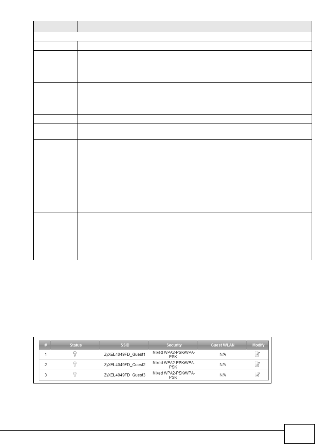
Chapter 6 Wireless
VMG8324-B10A / VMG8324-B30A Series User’s Guide 81
6.3 The More AP Screen
This screen allows you t o enable and configur e m ult iple Basic Service Sets ( BSSs) on t he Device.
Click N et w or k Set t ing > W ireless > M or e AP. The following screen displays.
Figure 39 Net work Set t ing > Wireless > More AP
Aut henticat ion Server
I P Address Enter t he I P address of t he external aut hent icat ion server in dot t ed decim al not ation.
Por t
Nu m ber
Ent er t he port num ber of t he ext ernal aut hentication server. The default port num ber is
1 8 1 2 .
You need not change this value unless your net work adm inistrat or inst ruct s you t o do so
with addit ional inform at ion.
Shared
Secret
Ent er a passw ord ( up t o 31 alphanum eric charact ers) as the key t o be shared bet w een t he
ext ernal authent icat ion server and t he Device.
The key m ust be t he sam e on t he ext ernal aut hent ication server and your Device. The key is
not sent over t he network.
m ore. ../ less Click m or e... t o show m ore fields in t his sect ion. Click less t o hide t hem .
WPA
Com pat ible
This field is only available for WPA2. Select this if you want t he Dev ice t o support WPA and
WPA2 sim ult aneously.
Encrypt ion Select t he encrypt ion t ype ( TKI P, AES or TKI P+ AES) for data encryption.
Select TKI P if your wireless client s can all use TKI P.
Select AES if your wir eless client s can all use AES.
Select TKI P+ AES t o allow t he w ireless client s to use eit her TKI P or AES.
WPA2 Pre-
Au t hen t icat ion
This field is available only when you select W PA2 .
Pre-aut hent icat ion enables fast roam ing by allowing t he wireless client ( already connect ing
to an AP) t o perform I EEE 802.1x aut hentication wit h another AP before connect ing t o it.
Select Ena ble d t o t urn on preauthentication in WAP2. Ot her wise, select Disa bled.
Net work Re-
aut h I nterval
Specify how oft en wir eless st ations have t o resend usernam es and passwor ds in order t o
st ay connect ed.
I f w ireless st at ion aut hent icat ion is done using a RADI US server, t he reaut hent ication t im er
on t he RADI US server has priority.
Group Key
Update Tim er
The Group Ke y U pda t e Tim e r is t he rat e at which t he RADI US server sends a new group
key out t o all client s.
Table 20 Wireless > General: Mor e Secure: WPA(2) ( cont inued)
LABEL DESCRIPTION

Chapter 6 Wireless
VMG8324-B10A / VMG8324-B30A Series User’s Guide
82
The following t able describes t he labels in this screen.
Table 21 Net work Set t ing > Wireless > More AP
LABEL DESCRIPTION
# This is the index num ber of the ent ry.
St atus This field indicat es whether t his SSI D is act ive. A yellow bulb signifies t hat t his SSI D is active.
A gray bulb signifies t hat t his SSI D is not act ive.
SSI D An SSI D profile is t he set of param et er s relat ing to one of t he Device’s BSSs. The SSI D
( Service Set I Dent ifier) ident ifies the Serv ice Set wit h which a wireless device is associat ed.
This field displays the nam e of t he wireless profile on t he net work . When a wireless client
scans for an AP to associate wit h, this is t he nam e t hat is broadcast and seen in t he wireless
client ut ilit y.
Securit y This field indicat es t he secur it y m ode of t he SSI D profile.
Guest WLAN This displays if t he guest WLAN funct ion has been enabled for t his WLAN.
I f H om e Gue st displays, client s can connect t o each other dir ectly.
I f Extern a l Gu est displays, client s are blocked from connecting to each ot her directly.
N / A displays if guest WLAN is disabled.
Modify Click the Edit icon t o configure t he SSI D profile.
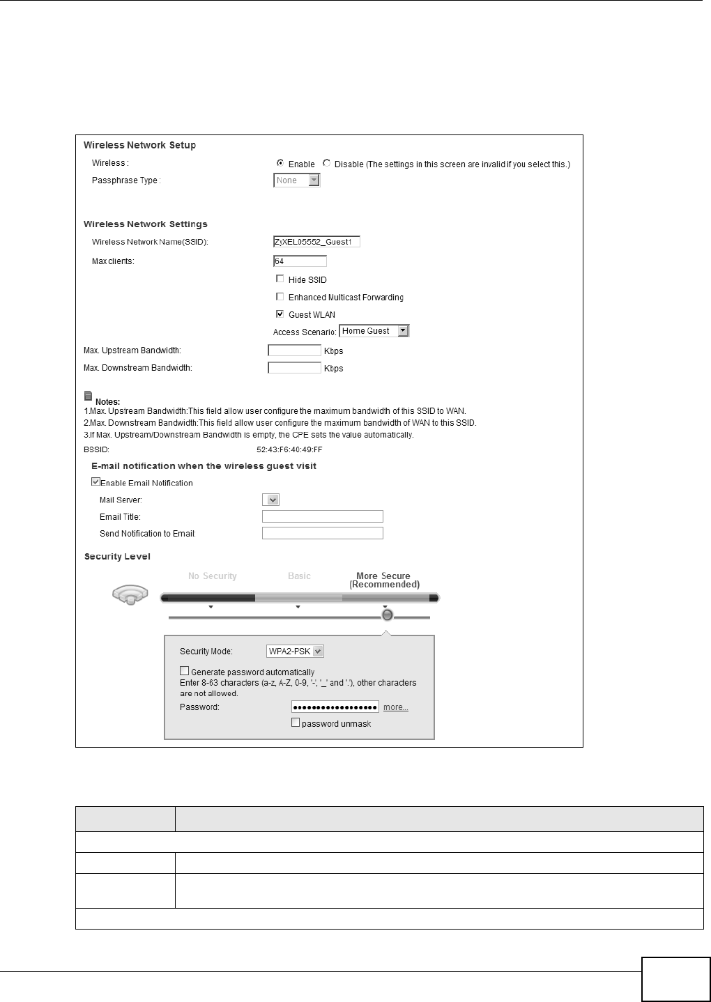
Chapter 6 Wireless
VMG8324-B10A / VMG8324-B30A Series User’s Guide 83
6.3.1 Edit More AP
Use t his screen t o edit an SSI D profile. Click t he Edit icon next t o an SSI D in t he M or e AP screen.
The following screen displays.
Figure 40 Net work Set t ing > Wireless > More AP > Edit
The following t able describes t he fields in this screen.
Table 22 Net work Sett ing > Wireless > More AP > Edit
LABEL DESCRIPTION
Wireless Netw ork Set up
Wireless You can En a ble or Disa ble t he wireless LAN in t his field.
Passphrase
Ty p e
Passphrase type cannot be changed. The default is N on e.
Wireless Netw ork Set t ings

Chapter 6 Wireless
VMG8324-B10A / VMG8324-B30A Series User’s Guide
84
Wireless
Net work Nam e
( SSI D)
The SSI D (Ser vice Set I Dent it y) identifies t he service set with which a wireless device is
associat ed. Wir eless devices associat ing t o t he access point (AP) m ust hav e t he sam e SSI D.
Ent er a descriptive nam e (up t o 32 English keyboar d characters) for t he w ireless LAN.
Max client s Specify t he m axim um num ber of clients t hat can connect t o t his net w ork at t he sam e t im e.
Hide SSI D Select t his check box t o hide the SSI D in the outgoing beacon fram e so a station cannot
obtain the SSI D through scanning using a sit e survey t ool.
Enhanced
Mult icast
Forwarding
Select t his check box to allow the Dev ice t o convert wireless m ult icast traffic int o wireless
unicast t raffic.
Guest WLAN Select t his to cr eat e Guest WLANs for hom e and external clients. Select the WLAN type in
the Acce ss Sce na r io field.
Access
Scenario
I f you select H om e Gu e st , client s can connect t o each ot her direct ly.
I f you select Ex t e r nal Guest , client s are blocked from connect ing t o each ot her directly.
Maxim um
Upst ream
Bandwidt h
Specify the m ax im um rat e for upst ream wireless traffic t o t he WAN from t his WLAN in
kilobit s per second ( Kbps).
Maxim um
Dow nst ream
Bandwidt h
Specify the m ax im um rat e for dow nst r eam wireless traffic t o t his WLAN from t he WAN in
kilobit s per second ( Kbps).
BSSI D This shows t he MAC address of t he wireless interface on t he Dev ice when wireless LAN is
enabled.
E- m ail not ificat ion when the wireless guest visit
Enable Em ail
Notification
Select t his t o have t he Dev ice e- m ail you a not ificat ion when a w ireless client is connected
to t he wireless net work.
Mail Ser ver Select a m ail server for the e-m ail address specified below.
I f you do not select a m ail ser ver, e- m ail notificat ions cannot be sent via e- m ail. You m ust
have configur ed a m ail server already in t he Maint ena n ce > Em ail N ot ifica t ion screen.
Em ail Tit le Type a tit le t hat you want t o be in the subj ect line of t he e-m ail not ifications t hat t he Device
sends.
Send
Notification t o
Em ail
Notificat ions are sent t o t he e- m ail address specified in t his field. I f t his field is left blank,
notificat ions cannot be sent via e-m ail.
Security Level
Security Mode Select Basic ( W EP, 8 0 2 .1 X ) or More Se cur e ( W PA( 2 ) - PSK, W PA( 2 ) ) t o add securit y
on t his wireless net w ork. The wireless client s which want to associate t o t his net work m ust
have sam e wireless security set t ings as the Device. Aft er you select t o use a security,
additional options appears in t his screen.
Or you can select N o Securit y t o allow any client t o associat e t his netw or k wit hout any data
encr ypt ion or aut hent ication.
See Sect ion 6.2.1 on page 75 for m ore det ails about t his field.
Apply Click Apply t o save your changes.
Cancel Click Ca ncel t o exit t his screen wit hout saving.
Table 22 Net work Sett ing > Wireless > More AP > Edit ( cont inued)
LABEL DESCRIPTION
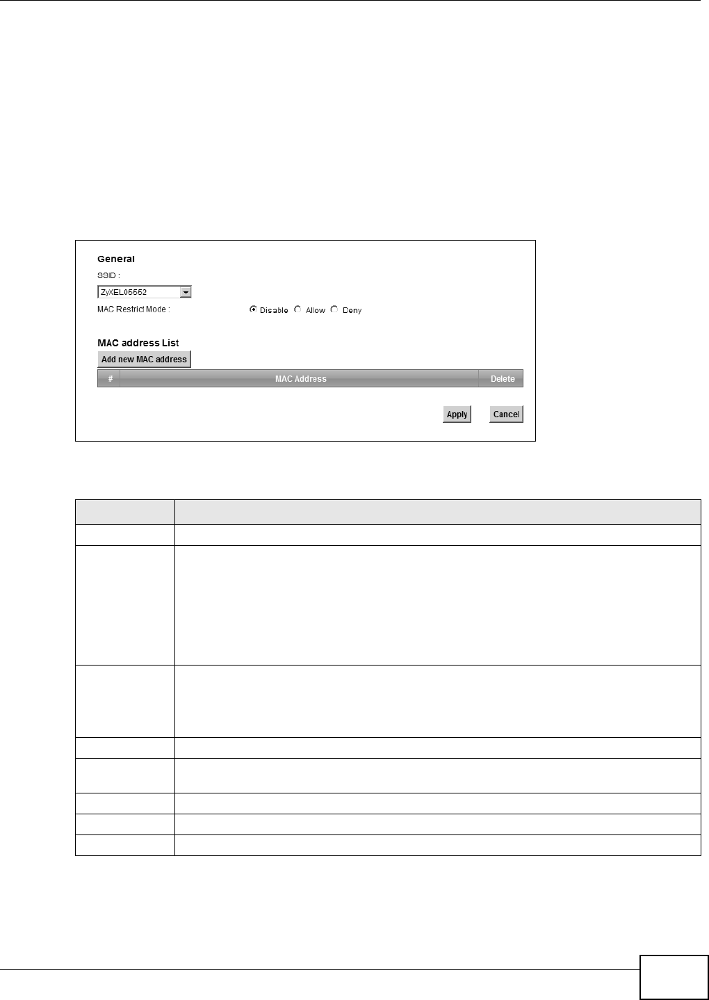
Chapter 6 Wireless
VMG8324-B10A / VMG8324-B30A Series User’s Guide 85
6.4 MAC Authentication
This screen allows you t o configure the ZyXEL Device t o give exclusive access to specific devices
( Allow ) or exclude specific devices from accessing the ZyXEL Device ( Deny) . Every Ethernet
device has a unique MAC ( Media Access Control) address. The MAC address is assigned at t he
fact ory and consist s of six pairs of hexadecim al charact ers, for exam ple, 00: A0: C5: 00: 00: 02. You
need t o know the MAC addresses of the devices to configure this screen.
Use t his screen t o view your Device’s MAC filt er set t ings and add new MAC filt er rules. Click
N e t w ork Se t t ing > W ir e less > M AC Aut he n t ica t ion . The screen appears as shown.
Figure 41 Wireless > MAC Authentication
The following t able describes t he labels in this screen.
Table 23 Wireless > MAC Aut hent icat ion
LABEL DESCRIPTION
SSI D Select the SSI D for which you want t o configure MAC filter set t ings.
MAC Restrict
Mode
Define t he filter action for t he list of MAC addresses in the MAC Addr ess table.
Select Disa ble t o turn off MAC filtering.
Select De n y t o block access t o t he Dev ice. MAC addresses not list ed will be allow ed to
access t he Device.
Select Allow t o perm it access t o t he Device. MAC addresses not listed will be denied access
to the Device.
Add new MAC
address
Click t his if you want to add a new MAC address ent ry to t he MAC filter list below.
Ent er t he MAC addresses of t he w ireless devices t hat are allowed or denied access to t he
Device in t hese address fields. Ent er the MAC addr esses in a valid MAC address form at , t hat
is, six hexadecim al character pairs, for ex am ple, 12: 34: 56: 78: 9a: bc.
#This is t he index num ber of t he ent ry.
MAC Address This is t he MAC addresses of t he wireless devices that are allowed or denied access to t he
Device.
Delet e Click t he D e le t e icon t o delet e t he entry.
Apply Click Apply to save your changes.
Cancel Click Ca n cel t o exit this screen wit hout saving.
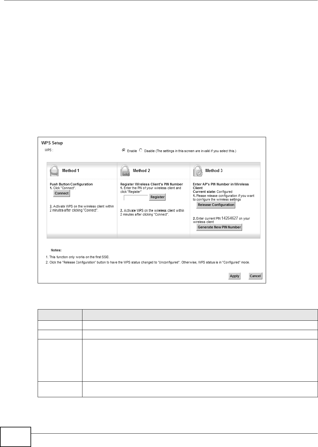
Chapter 6 Wireless
VMG8324-B10A / VMG8324-B30A Series User’s Guide
86
6.5 The WPS Screen
Use t his screen to configure WiFi Protect ed Set up ( WPS) on your Device.
WPS allows you to quickly set up a wireless network wit h st rong securit y, without having t o
configure security set t ings m anually. Set up each WPS connect ion between two devices. Both
devices m ust support WPS. See Sect ion 6.10.9.3 on page 101 for m ore inform at ion about WPS.
Not e: The Device applies the security set t ings of t he SSI D1 profile ( see Section 6.2 on
page 72) . I f you want to use t he WPS feat ure, m ake sure you have set t he securit y
m ode of SSI D1 t o W PA2 - PSK or N o Secur it y.
Click N e t w ork Se t t ing > W ireless > W PS. The following scr een displays. Select Ena ble and click
Apply t o activat e the WPS funct ion. Then you can configure the WPS set t ings in t his screen.
Figure 42 Net work Set t ing > Wireless > WPS
The following t able describes t he labels in this screen.
Table 24 Net work Sett ing > Wireless > WPS
LABEL DESCRIPTION
WPS Select Enable t o activat e WPS on t he Device.
Met hod 1 Use this sect ion to set up a WPS wireless net w ork using Push But ton Configurat ion ( PBC).
Connect Click t his button t o add anot her WPS- enabled wireless device ( wit hin wireless range of t he
Device) t o your wireless net work. This but t on m ay eit her be a physical but t on on t he
out side of device, or a m enu button sim ilar t o t he Conne ct but t on on this screen.
Note: You must press the other wireless device’s WPS button within two minutes of pressing
this button.
Met hod 2 Use t his sect ion to set up a WPS wireless net w ork by entering the PI N of the client int o t he
Device.
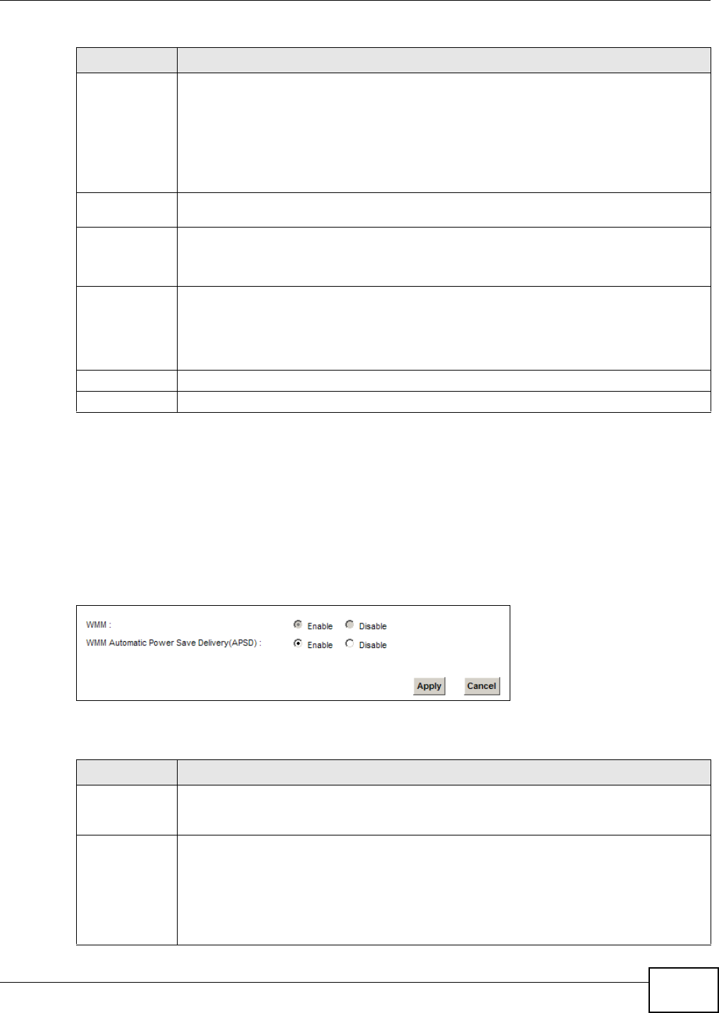
Chapter 6 Wireless
VMG8324-B10A / VMG8324-B30A Series User’s Guide 87
6.6 The WMM Screen
Use t his scr een t o enable Wi- Fi Mult iMedia ( WMM) and WMM Power Save in wireless net works for
m ultim edia applicat ions.
Click N et w or k Set t ing > W ireless > W MM . The following screen displays.
Figure 43 Net work Set t ing > Wireless > WMM
The following t able describes t he labels in this screen.
Regist er Enter t he PI N of the device t hat you are setting up a WPS connection w it h and click
Re gist e r t o authent icat e and add the w ireless device t o your wireless net w ork.
You can find t he PI N eit her on the out side of t he device, or by checking t he device’s
set t ings.
Note: You must also activate WPS on that device within two minutes to have it present its PIN
to the Device.
Met hod 3 Use this sect ion to set up a WPS wireless net work by entering t he PI N of t he Device int o t he
client.
Release
Configurat io
n
The default WPS st at us is configured.
Click t his but t on t o rem ove all configur ed wireless and wir eless security set t ings for WPS
connect ions on t he Device.
Generat e
New PI N
Nu m ber
The PI N ( Personal I dent ificat ion Num ber ) of the Device is shown here. Ent er this PI N in the
configurat ion ut ilit y of t he device you want to connect t o using WPS.
The PI N is not necessar y when you use WPS push- but t on m ethod.
Click the Gen era t e N e w PI N N um be r but t on to have t he Device create a new PI N.
Apply Click Apply t o save your changes.
Cancel Click Cance l to rest or e your pr eviously saved set t ings.
Table 24 Net work Sett ing > Wireless > WPS ( continued)
LABEL DESCRIPTION
Table 25 Net work Sett ing > Wireless > WMM
LABEL DESCRIPTION
WMM Select On t o have t he Device aut om at ically give a ser vice a priority level according to t he
ToS value in t he I P header of pack et s it sends. WMM QoS ( Wifi MultiMedia Qualit y of
Serv ice) gives high pr iorit y to voice and video, which m akes t hem run m ore sm oot hly.
WMM
Aut om at ic
Pow er Save
Delivery
Select this opt ion to ext end the bat t ery life of your m obile devices ( especially useful for
sm all devices t hat are r unning m ultim edia applications) . The Device goes to sleep m ode t o
sav e power when it is not t ransm itting dat a. The AP buffers the packet s sent t o t he Device
unt il t he Device "wakes up". The Device wakes up periodically t o check for incom ing data.
Note: Note: This works only if the wireless device to which the Device is connected also
supports this feature.
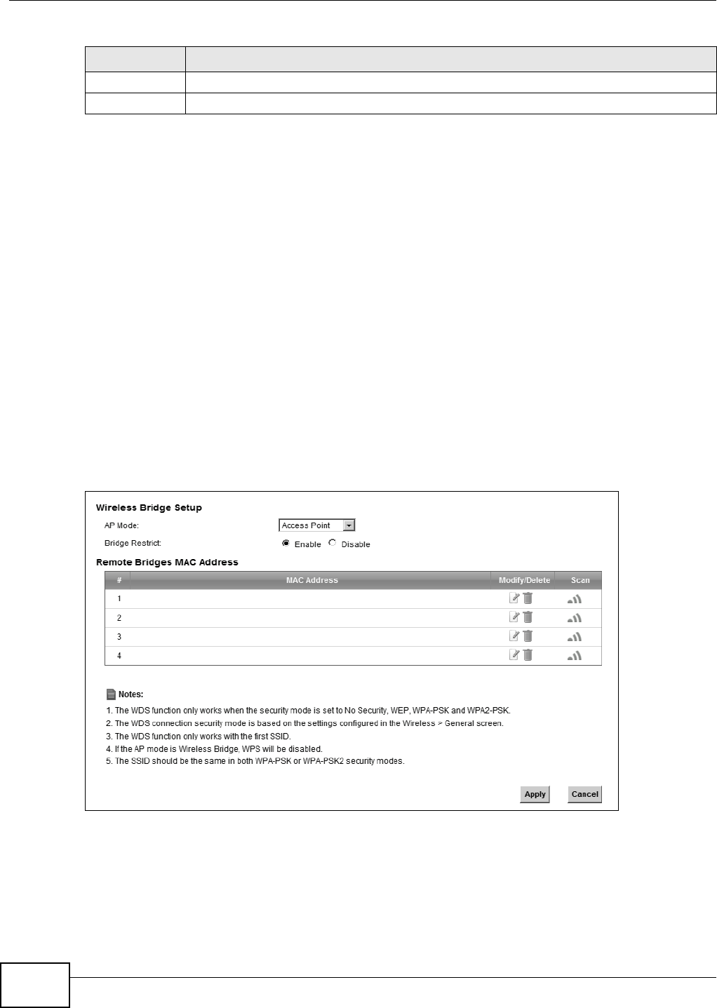
Chapter 6 Wireless
VMG8324-B10A / VMG8324-B30A Series User’s Guide
88
6.7 The WDS Screen
An AP using t he Wireless Dist ribut ion Syst em ( WDS) can function as a wireless net work bridge
allowing you t o wirelessly connect t wo wir ed network segm ent s. The W DS screen allows you t o
configure the Device t o connect t o t w o or m ore APs wirelessly when WDS is enabled.
Use t his screen to set up your WDS ( Wireless Dist ribution System ) links bet ween t he Device and
ot her wireless APs. You need to know the MAC address of t he peer device. Once the security
sett ings of peer sides m at ch one anot her, t he connect ion bet ween devices is m ade.
Note: WDS security is independent of t he securit y set t ings between t he Device and any
wireless client s.
Not e: At t he t im e of writ ing, WDS is com pat ible with ot her ZyXEL APs only. Not all m odels
support WDS links. Check your other AP’s docum ent ation.
Click N et w or k Set t ing > W ireless > W DS. The following screen displays.
Figure 44 Net work Set t ing > Wireless > WDS
Apply Click Apply t o save your changes.
Cancel Click Ca n cel t o restore your prev iously saved sett ings.
Table 25 Net work Set t ing > Wireless > WMM ( cont inued)
LABEL DESCRIPTION
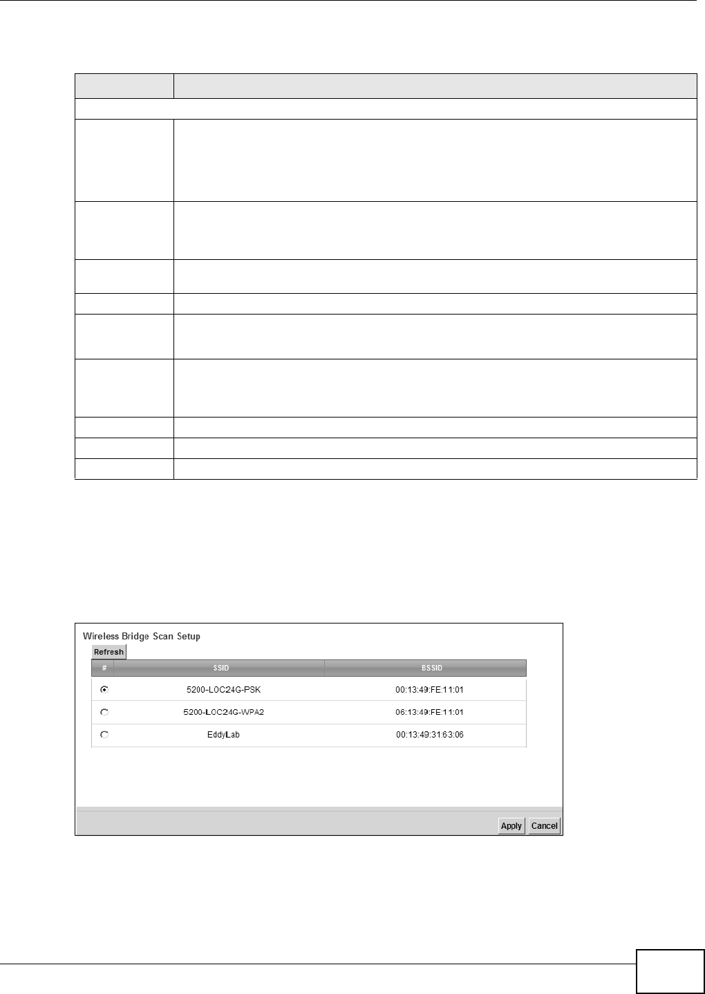
Chapter 6 Wireless
VMG8324-B10A / VMG8324-B30A Series User’s Guide 89
The following t able describes t he labels in this screen.
6.7.1 WDS Scan
You can click t he Sca n icon in W ireless > W DS t o have t he Device aut om atically search and
display t he available APs wit hin range. Select an AP and click Apply t o have the Device est ablish a
wireless link with t he selected wireless device.
Figure 45 WDS: Scan
Table 26 Net work Sett ing > Wireless > WDS
LABEL DESCRIPTION
Wireless Bridge Setup
AP Mode Select t he operating m ode for your Dev ice.
•Acce ss Poin t - The Dev ice funct ions as a bridge and access point sim ultaneously.
•W ir e less Br idge - The Device act s as a wireless net w ork bridge and est ablishes
wireless links with ot her APs. I n t his m ode, client s cannot connect to t he Device
wirelessly.
Bridge Rest rict This field is available only when you set operat ing m ode t o Acce ss Poin t .
Select Ena bled to t urn on WDS and ent er t he peer device’s MAC address m anually in the
table below. Select D isable t o t ur n off WDS.
Rem ote Bridge
MAC Address
You can ent er t he MAC address of t he peer device by clicking the Edit icon under M odify.
# This is the index num ber of t he entry.
MAC Address This shows the MAC address of t he peer device.
You can connect t o up t o 4 peer devices.
Modify Click t he Edit icon and type the MAC address of the peer device in a valid MAC address
form at ( six hexadecim al charact er pair s, for exam ple 12: 34: 56: 78: 9a: bc).
Click the D e let e icon t o rem ove this ent r y.
Scan Click t he Sca n icon t o search and display the available APs wit hin range.
Apply Click Apply t o save your changes.
Cancel Click Ca n cel t o restore your prev iously saved sett ings.
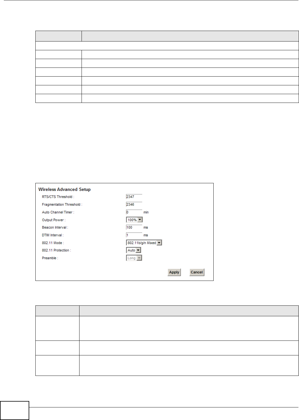
Chapter 6 Wireless
VMG8324-B10A / VMG8324-B30A Series User’s Guide
90
The following t able describes t he labels in this screen.
6.8 The Others Screen
Use t his screen t o configure advanced wireless set t ings. Click N e t w or k Se t t ing > W ireless >
Ot h er s. The screen appears as shown.
See Sect ion 6.10.2 on page 94 for detailed definit ions of t he term s listed in t his scr een.
Figure 46 Net work Set t ing > Wireless > Ot hers
The following t able describes t he labels in this screen.
Table 27 WDS: Scan
LABEL DESCRIPTION
Wireless Bridge Scan Setup
Refresh Click Refr esh t o updat e t he t able.
# This is t he index num ber of the ent ry.
SSI D This shows t he SSI D of t he available wir eless dev ice wit hin range.
BSSI D This show s t he MAC address of t he available wireless device wit hin range.
Apply Click Apply t o save your changes.
Cancel Click Cancel t o r est ore your previously saved set t ings.
Table 28 Net work Set t ing > Wireless > Other s
LABEL DESCRIPTION
RTS/ CTS
Threshold
Dat a wit h it s fram e size larger t han t his value will perform t he RTS ( Request To Send) / CTS
( Clear To Send) handshake.
Enter a value bet ween 0 and 2347.
Fragm ent ation
Threshold
This is the m ax im um data fragm ent size that can be sent. Enter a value bet ween 256 and
2346.
Aut o Channel
Tim er
I f you set t he channel to Au t o in the N e t w ork Set t ing > W irele ss > Ge n e r a l screen,
specify the int erval in m inutes for how oft en t he Device scans for t he best channel. Enter 0
to disable the periodical scan.

Chapter 6 Wireless
VMG8324-B10A / VMG8324-B30A Series User’s Guide 91
Output Power Set t he output pow er of t he Device. I f t her e is a high densit y of APs in an area, decrease
the output power to reduce int er ference with ot her APs. Select one of t he follow ing: 2 0 % ,
4 0 % , 6 0 % , 8 0 % or 1 0 0 % .
Beacon I nt erval When a wirelessly net worked dev ice sends a beacon, it includes w it h it a beacon int erval.
This specifies the tim e period before t he device sends t he beacon again.
The interval t ells receiv ing devices on t he net work how long t hey can w ait in low pow er
m ode befor e waking up t o handle t he beacon. This value can be set from 50m s to 1000m s.
A high value helps save current consum ption of t he access point .
DTI M I n t er val Delivery Traffic I ndication Message ( DTI M) is t he t im e period after which broadcast and
m ulticast packet s are t ransm it t ed t o m obile clients in t he Power Saving m ode. A high DTI M
value can cause clients t o lose connect iv it y wit h t he net work. This value can be set from 1
to 255.
802.11 Mode Select 8 0 2 .1 1 b Only t o allow only I EEE 802.11b com pliant WLAN devices t o associat e w it h
the Dev ice.
Select 8 0 2 .1 1 g Only t o allow only I EEE 802.11g com pliant WLAN devices t o associat e wit h
the Dev ice.
Select 8 0 2 .1 1 n Only to allow only I EEE 802.11n com pliant WLAN devices t o associat e w it h
the Dev ice.
Select 8 0 2 .1 1 b/ g M ix ed t o allow eit her I EEE 802.11b or I EEE 802.11g com pliant WLAN
devices t o associat e w it h t he Device. The t ransm ission rat e of y our Device m ight be
reduced.
Select 8 0 2 .1 1 b/ g/ n M ixed to allow I EEE 802.11b, I EEE 802.11g or I EEE802.11n
com pliant WLAN devices to associat e wit h the Device. The t ransm ission rate of your Dev ice
m ight be reduced.
802.11
Prot ect ion
Enabling t his feat ure can help pr event collisions in m ixed-m ode networks ( net w or ks with
both I EEE 802.11b and I EEE 802.11g t raffic) .
Select Aut o t o have t he w ireless devices t ransm it data aft er a RTS/ CTS handshake. This
helps im prove I EEE 802.11g perform ance.
Select Off t o disable 802.11 prot ect ion. The transm ission rate of your Device m ight be
reduced in a m ixed- m ode net work .
This field displays Off and is not configurable when you set 8 0 2 .1 1 M ode t o 8 0 2 .1 1 b
Only.
Pr eam ble Select a pream ble t ype fr om t he drop-down list box. Choices ar e Lon g or Sh or t . See
Sect ion 6.10.7 on page 98 for m ore inform at ion.
This field is configurable only when you set 802.11 Mode t o 8 0 2 .1 1 b.
Apply Click Apply t o save your changes.
Cancel Click Cancel t o rest ore your previously saved set t ings.
Table 28 Net work Set t ing > Wireless > Other s ( cont inued)
LABEL DESCRIPTION
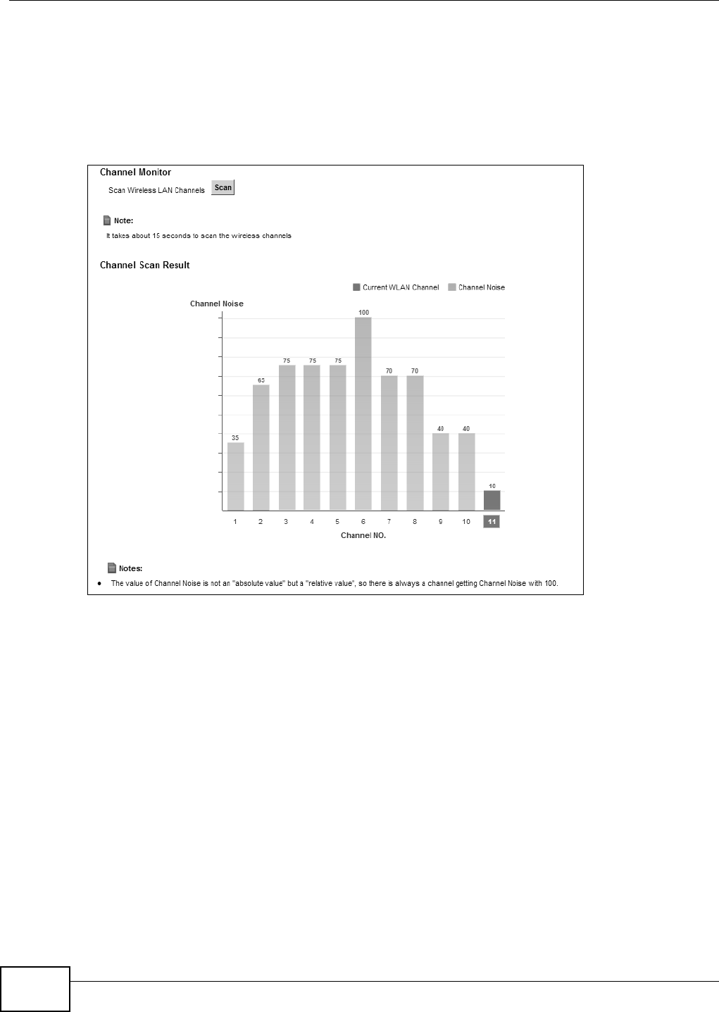
Chapter 6 Wireless
VMG8324-B10A / VMG8324-B30A Series User’s Guide
92
6.9 The Channel Status Screen
Use t he Cha nnel Sta t us screen to scan wireless LAN channel noises and view the results. Click
N e t w ork Se t t ing > W ire le ss > Channel St a t us. The screen appears as shown. Click Sca n t o
scan the w ireless LAN channels. You can view t he results in the Ch a nnel Sca n Result sect ion.
Figure 47 Net work Sett ing > Wireless > Channel St atus
6.10 Technical Reference
This sect ion discusses wireless LANs in dept h. For m ore inform at ion, see Appendix E on page 375.
6.10.1 Wireless Network Overview
Wireless net works consist of wireless clients, access point s and bridges.
• A wireless client is a radio connect ed to a user ’s com put er.
• An access point is a radio wit h a wired connect ion to a net work, which can connect wit h
num erous w ireless client s and let t hem access t he net w ork.
• A bridge is a radio t hat relays com m unicat ions bet ween access point s and wireless client s,
extending a net w ork’s range.
Tradit ionally, a wireless network operat es in one of two ways.
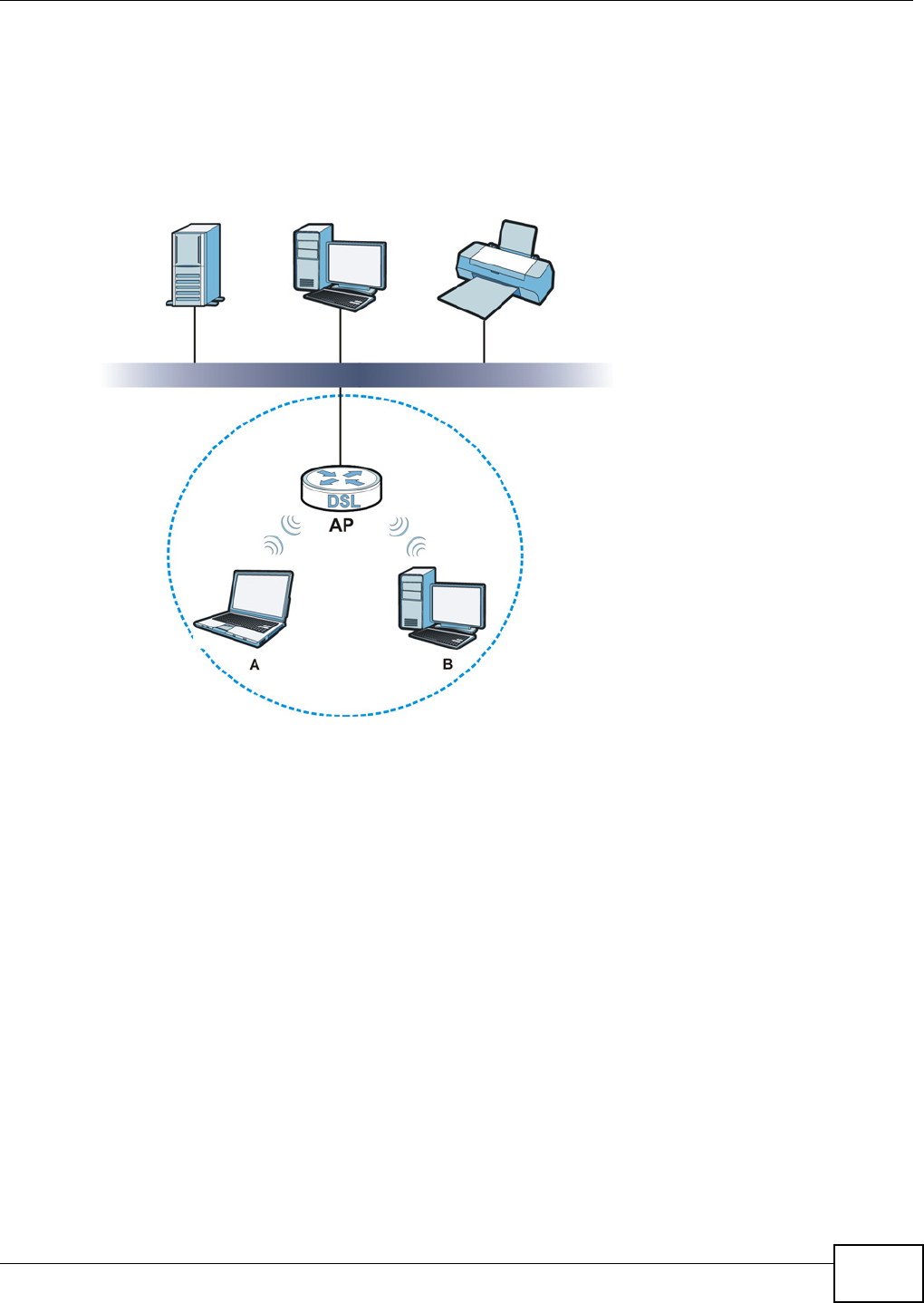
Chapter 6 Wireless
VMG8324-B10A / VMG8324-B30A Series User’s Guide 93
• An “ infrast ruct ure” type of net work has one or m ore access points and one or m ore w ireless
clients. The wireless client s connect t o the access point s.
• An “ ad-hoc” t ype of net work is one in which there is no access point. Wireless client s connect t o
one another in order t o exchange inform ation.
The following figure provides an exam ple of a wir eless net w ork.
Figure 48 Exam ple of a Wireless Network
The wireless network is t he part in t he blue circle. I n t his wireless network, devices A and B use t he
access point (AP) t o int eract wit h t he ot her devices ( such as the print er) or with t he I nt er net. Your
Device is t he AP.
Every wireless net work m ust follow these basic guidelines.
• Every device in the sam e wireless net work m ust use t he sam e SSI D.
The SSI D is t he nam e of t he wir eless net w ork. I t st ands for Service Set I Dent ifier.
• I f t w o wireless networks overlap, t hey should use a different channel.
Like radio st at ions or t elevision channels, each wireless network uses a specific channel, or
frequency, to send and receive inform at ion.
• Every device in the sam e wireless net work m ust use securit y com pat ible wit h the AP.
Securit y st ops unaut hor ized devices from using the wireless net work. I t can also protect t he
inform ation t hat is sent in t he wireless net work.
Radio Channels
I n t he radio spectrum , t here are cert ain frequency bands allocat ed for unlicensed, civilian use. For
the purposes of w ireless networking, t hese bands are divided into num erous channels. This allows a

Chapter 6 Wireless
VMG8324-B10A / VMG8324-B30A Series User’s Guide
94
variety of networks t o exist in the sam e place wit hout int erfering wit h one anot her. When you
create a net work, you m ust select a channel t o use.
Since t he available unlicensed spect rum varies fr om one country t o another, t he num ber of
available channels also varies.
6.10.2 Additional Wireless Terms
The following t able describes som e wireless net w ork t erm s and acronym s used in the Device’s Web
Configurat or.
6.10.3 Wireless Security Overview
By t heir nat ure, radio com m unicat ions are sim ple to int ercept. For wireless dat a net w orks, t his
m eans t hat anyone wit hin range of a wireless net wor k wit hout securit y can not only read t he dat a
passing over t he airwaves, but also j oin the net w ork. Once an unauthorized person has access t o
the net w ork, he or she can steal inform at ion or int roduce m alware ( m alicious soft ware) int ended t o
com prom ise the net work. For these reasons, a variet y of security syst em s have been developed to
ensure t hat only aut horized people can use a w ireless data net work, or underst and t he dat a carried
on it .
These securit y st andards do two things. First , t hey authenticate. This m eans t hat only people
presenting t he right credent ials (often a usernam e and password, or a “ key” phrase) can access the
net work. Second, t hey encrypt. This m eans t hat the inform ation sent over t he air is encoded. Only
people with t he code key can underst and t he infor m at ion, and only people w ho have been
aut hent icat ed are given t he code key.
These securit y st andards vary in effect iveness. Som e can be broken, such as t he old Wired
Equivalent Protocol ( WEP). Using WEP is bett er t han using no securit y at all, but it will not keep a
det erm ined at t acker out . Ot her securit y st andards are secure in t hem selves but can be broken if a
user does not use t hem properly. For exam ple, the WPA- PSK security st andard is very secure if you
use a long key which is difficult for an at tacker’s software t o guess - for exam ple, a t went y- let ter
long string of apparent ly random num bers and lett er s - but it is not very secure if you use a short
key which is very easy to guess - for exam ple, a three- lett er word from t he dict ionary.
Table 29 Addit ional Wireless Term s
TERM DESCRIPTION
RTS/ CTS Threshold I n a wireless net work which covers a large area, wireless devices are som et im es not
aware of each ot her ’s presence. This m ay cause t hem to send inform ation to the AP
at t he sam e t im e and result in inform ation colliding and not getting through.
By set ting this value lower t han t he default value, t he wireless devices m ust
som etim es get perm ission t o send inform at ion to the Device. The lower the value, the
m ore often the devices m ust get per m ission.
I f t his value is greater than t he fragm entat ion t hreshold value (see below), then
wireless devices never have t o get perm ission t o send inform at ion t o t he Device.
Pream ble A pream ble affect s t he t im ing in your wireless net work. There are t w o pream ble
m odes: long and short. I f a device uses a different pream ble m ode t han the Device
does, it cannot com m unicat e wit h the Device.
Aut hent ication The process of verifying whether a wireless device is allowed t o use t he wireless
net work.
Fragm ent ation
Threshold
A sm all fragm entat ion thr eshold is recom m ended for busy net works, while a larger
threshold provides fast er perform ance if t he net work is not ver y busy.

Chapter 6 Wireless
VMG8324-B10A / VMG8324-B30A Series User’s Guide 95
Because of t he dam age t hat can be done by a m alicious att acker, it ’s not j ust people who have
sensitive inform ation on t heir network who should use security. Everybody w ho uses any wireless
net work should ensure t hat effective securit y is in place.
A good way to com e up w ith effect ive security keys, passwords and so on is t o use obscure
inform ation t hat you personally will easily rem em ber, and to ent er it in a way t hat appears random
and does not include real words. For exam ple, if your m ot her owns a 1970 Dodge Challenger and
her favorit e m ovie is Vanishing Point ( which you know was m ade in 1971) you could use
“ 70dodchal71vanpoi” as your securit y key.
The following sections introduce different t ypes of wireless securit y you can set up in t he wireless
net work.
6.10.3.1 SSID
Norm ally, t he Device act s like a beacon and regularly broadcast s t he SSI D in the area. You can hide
the SSI D inst ead, in which case t he Device does not broadcast t he SSI D. I n addit ion, you should
change t he default SSI D to som et hing t hat is difficult t o guess.
This t y pe of security is fairly weak, however, because ther e are ways for unaut hor ized wireless
devices t o get the SSI D. I n addit ion, unauthorized w ireless devices can still see t he inform at ion t hat
is sent in the wireless net work.
6.10.3.2 MAC Address Filter
Every device t hat can use a wir eless net work has a unique identificat ion num ber, called a MAC
address.1 A MAC address is usually writt en using t welve hexadecim al charact ers2; for exam ple,
00A0C5000002 or 00: A0: C5: 00: 00: 02. To get t he MAC address for each device in t he wireless
net work, see the device’s User’s Guide or other docum ent at ion.
You can use t he MAC addr ess filt er t o tell t he Device w hich devices are allow ed or not allowed t o
use t he wireless net work. I f a device is allowed t o use t he wireless net work, it st ill has t o have the
corr ect inform ation ( SSI D, channel, and security). I f a device is not allowed t o use t he w ireless
net work, it does not m at t er if it has t he correct inform at ion.
This t y pe of security does not prot ect t he inform at ion that is sent in t he wireless net work.
Furtherm ore, t here are ways for unaut horized wireless devices t o get t he MAC address of an
aut horized device. Then, t hey can use t hat MAC address t o use t he wireless net work.
6.10.3.3 User Authentication
Aut hent icat ion is the process of verifying whet her a wireless device is allowed to use t he wireless
net work. You can m ake every user log in t o the w ireless net work before using it . However, every
device in t he wireless network has t o support I EEE 802.1x t o do t his.
For wireless net works, you can store the user nam es and passw ords for each user in a RADI US
server. This is a server used in businesses m ore t han in hom es. I f you do not have a RADI US server,
you cannot set up user nam es and passwords for your users.
Unauthorized wireless devices can st ill see the inform at ion t hat is sent in the wireless network,
even if t hey cannot use the wireless net work. Furtherm ore, there are ways for unaut horized
1. Some wireless devices, such as scanners, can detect wireless networks but cannot use wireless networks. These kinds
of wireless devices might not have MAC addresses.
2. Hexadecimal characters are 0, 1, 2, 3, 4, 5, 6, 7, 8, 9, A, B, C, D, E, and F.

Chapter 6 Wireless
VMG8324-B10A / VMG8324-B30A Series User’s Guide
96
wireless users t o get a valid user nam e and password. Then, t hey can use that user nam e and
password t o use the wireless net work.
6.10.3.4 Encryption
Wireless net works can use encryption t o prot ect t he inform ation t hat is sent in t he wireless
net work. Encrypt ion is like a secret code. I f you do not know t he secret code, you cannot
underst and the m essage.
The t ypes of encryption you can choose depend on the type of aut hent ication. ( See Sect ion
6.10.3.3 on page 95 for inform at ion about this.)
For exam ple, if the wireless network has a RADI US server, you can choose W PA or W PA2 . I f users
do not log in t o t he wir eless net work, you can choose no encr yption, Sta t ic W EP, W PA- PSK, or
W PA2 - PSK.
Usually, you should set up t he st rongest encryption t hat every device in t he w ireless net work
supports. For exam ple, suppose you have a wireless net work with t he Device and you do not have
a RADI US server. Therefore, t here is no aut hent ication. Suppose t he wireless network has t wo
devices. Device A only support s WEP, and device B support s WEP and WPA. Ther efore, you should
set up St a t ic W EP in t he wireless net work.
Not e: I t is recom m ended that wireless net works use W PA- PSK, W PA, or st ronger
encrypt ion. The ot her types of encrypt ion are bet t er than none at all, but it is st ill
possible for unaut horized wireless devices t o figure out the original inform ation
pret t y quickly.
When you select W PA2 or W PA2 - PSK in your Device, you can also select an option (W PA
com pat ible ) t o support WPA as well. I n t his case, if som e of t he devices support WPA and som e
support WPA2, you should set up W PA2 - PSK or W PA2 ( depending on the t ype of w ireless net work
login) and select the W PA com pa t ible opt ion in t he Device.
Many t ypes of encrypt ion use a key t o prot ect the inform at ion in t he wireless net work. The longer
the key, t he st ronger the encrypt ion. Every device in t he wireless net work m ust have t he sam e key.
6.10.4 Signal Problems
Because wireless networks are radio networks, t heir signals are subj ect t o lim it at ions of dist ance,
int erference and absorpt ion.
Problem s with dist ance occur when t he two radios are t oo far apart . Problem s w ith int erference
occur w hen ot her radio waves interrupt t he dat a signal. I nt erference m ay com e from other radio
transm issions, such as m ilitary or air t raffic cont rol com m unicat ions, or from m achines that are
Table 30 Types of Encr ypt ion for Each Type of Aut hentication
NO AUTHENTICATION RADIUS SERVER
W ea k est No Secur it y WPA
St at ic WEP
WPA- PSK
St r on g est WPA2 - PSK WPA2
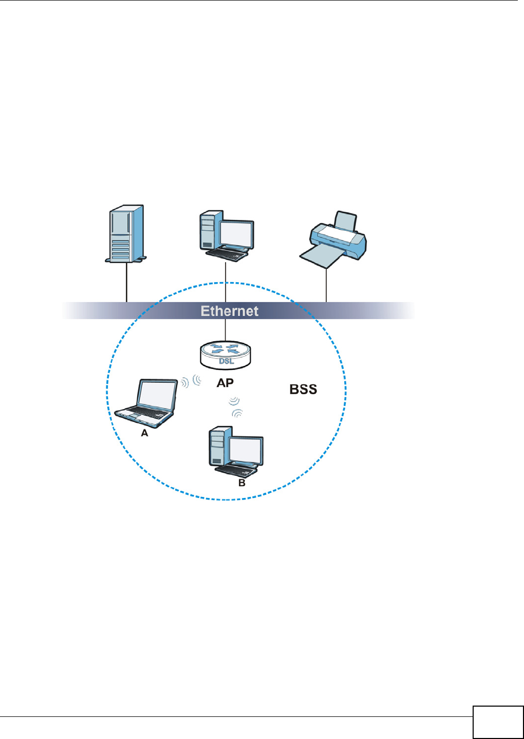
Chapter 6 Wireless
VMG8324-B10A / VMG8324-B30A Series User’s Guide 97
coincident al em it t ers such as elect ric m ot ors or m icrowaves. Problem s wit h absorption occur when
physical obj ect s ( such as thick walls) are bet ween t he two radios, m uffling t he signal.
6.10.5 BSS
A Basic Service Set ( BSS) exist s when all com m unicat ions bet ween wireless st at ions or bet ween a
wireless st ation and a wired net work client go t hrough one access point ( AP) .
I nt ra- BSS t raffic is t raffic bet ween wireless st at ions in t he BSS. When I nt ra- BSS t raffic blocking is
disabled, wireless stat ion A and B can access t he wired network and com m unicat e wit h each ot her.
When I nt ra-BSS t raffic blocking is enabled, wireless st at ion A and B can st ill access the wired
net work but cannot com m unicate with each ot her.
Figure 49 Basic Service set
6.10.6 MBSSID
Tradit ionally, you need t o use different APs to configure different Basic Service Set s ( BSSs) . As w ell
as t he cost of buying extra APs, there is also the possibility of channel interference. The Device’s
MBSSI D ( Mult iple Basic Service Set I Dentifier) funct ion allows you to use one access point t o
provide several BSSs sim ult aneously. You can then assign varying QoS priorit ies and/ or securit y
m odes t o different SSI Ds.
Wireless devices can use different BSSI Ds t o associat e with t he sam e AP.
6.10.6.1 Notes on Multiple BSSs
• A m axim um of eight BSSs are allowed on one AP sim ultaneously.
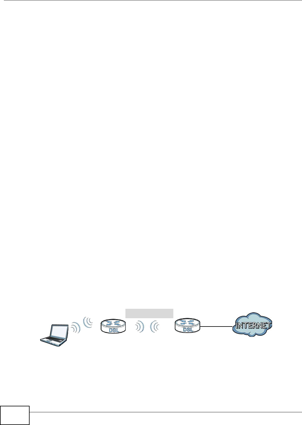
Chapter 6 Wireless
VMG8324-B10A / VMG8324-B30A Series User’s Guide
98
• You m ust use different keys for different BSSs. I f t wo wireless devices have different BSSI Ds
( t hey are in different BSSs), but have t he sam e keys, t hey m ay hear each ot her ’s
com m unicat ions ( but not com m unicate with each ot her) .
• MBSSI D should not replace but rat her be used in conj unction w ith 802.1x security.
6.10.7 Preamble Type
Pream ble is used t o signal t hat data is com ing t o t he receiver. Short and long refer t o the lengt h of
the synchronizat ion field in a packet.
Short pream ble increases perform ance as less tim e sending pream ble m eans m ore t im e for sending
dat a. All I EEE 802.11 com pliant wireless adapters support long pream ble, but not all support short
pream ble.
Use long pream ble if you are unsure what pream ble m ode other wireless devices on t he net work
support, and t o provide m ore reliable com m unicat ions in busy wireless net works.
Use short pream ble if you are sure all wireless devices on t he net work support it , and to provide
m ore efficient com m unicat ions.
Use t he dynam ic set t ing to aut om at ically use shor t pream ble when all wireless devices on t he
net work support it , ot herwise t he Device uses long pream ble.
Note: The w ireless devices MUST use the sam e pream ble m ode in order t o com m unicate.
6.10.8 Wireless Distribution System (WDS)
The Device can act as a wireless net work bridge and est ablish WDS ( Wireless Dist ribut ion Syst em )
links w ith other APs. You need to know the MAC addresses of the APs you want to link t o. Once t he
security set t ings of peer sides m at ch one another, t he connect ion bet ween devices is m ade.
At t he t im e of writ ing, WDS security is com pat ible with other ZyXEL access point s only. Refer to
your ot her access point ’s docum ent at ion for details.
The following figure illust rat es how WDS link works bet w een APs. Not ebook com put er A is a
wireless client connecting to access point AP 1 . AP 1 has no wired I nternet connect ion, but it can
establish a WDS link with access point AP 2 , which has a w ired I nt ernet connect ion. When AP 1
has a WDS link wit h AP 2 , t he not ebook com puter can access the I nt ernet t hrough AP 2 .
Figure 50 WDS Link Exam ple
6.10.9 WiFi Protected Setup (WPS)
Your Device support s WiFi Prot ected Set up ( WPS) , w hich is an easy way t o set up a secure wireless
net work. WPS is an indust ry st andard specification, defined by the WiFi Alliance.
WDS
AP 2
AP 1
A

Chapter 6 Wireless
VMG8324-B10A / VMG8324-B30A Series User’s Guide 99
WPS allows you to quickly set up a wireless network wit h st rong securit y, without having t o
configure security set t ings m anually. Each WPS connection w orks bet w een t w o devices. Both
devices m ust support WPS ( check each device’s docum ent at ion t o m ake sure) .
Depending on t he devices you have, you can either press a but t on ( on t he device it self, or in it s
configurat ion ut ility) or ent er a PI N ( a unique Personal I dentificat ion Num ber that allows one device
to aut hent icat e t he ot her) in each of the two devices. When WPS is act ivat ed on a device, it has t wo
m inutes t o find anot her device that also has WPS activat ed. Then, t he t wo devices connect and set
up a secure network by them selves.
6.10.9.1 Push Button Configuration
WPS Push But t on Configurat ion ( PBC) is initiat ed by pressing a butt on on each WPS- enabled
device, and allowing them t o connect aut om at ically. You do not need to ent er any inform at ion.
Not every WPS- enabled device has a physical WPS butt on. Som e m ay have a WPS PBC but ton in
their configuration utilities inst ead of or in addit ion to the physical but t on.
Take the following st eps to set up WPS using t he but t on.
1Ensure t hat t he two devices you want t o set up are within wireless range of one anot her.
2Look for a WPS butt on on each device. I f the device does not have one, log into it s configurat ion
ut ility and locat e t he but ton ( see the device’s User’s Guide for how t o do t his - for the Device, see
Sect ion 6.6 on page 87) .
3Press t he but t on on one of the devices (it doesn’t m at t er which) . For t he Device you m ust press t he
WPS but t on for m ore than t hree seconds.
4Within two m inutes, press t he but t on on the ot her device. The registrar sends t he net work nam e
( SSI D) and securit y key t hrough an secure connection to t he enrollee.
I f you need t o m ake sure that WPS worked, check t he list of associated wireless clients in the AP’s
configurat ion ut ilit y. I f you see t he wireless client in t he list , WPS was successful.
6.10.9.2 PIN Configuration
Each WPS- enabled device has it s own PI N ( Personal I dent ification Num ber ) . This m ay eit her be
st at ic ( it cannot be changed) or dynam ic ( in som e devices you can generat e a new PI N by clicking
on a but t on in the configurat ion int er face) .
Use t he PI N m et hod inst ead of t he push- but t on configurat ion ( PBC) m ethod if you want t o ensure
that t he connection is established between the devices you specify, not j ust t he first t wo devices to
activat e WPS in range of each ot her. However, you need to log into the configurat ion int erfaces of
bot h devices t o use the PI N m et hod.
When you use t he PI N m et hod, you m ust enter t he PI N from one device ( usually the wireless client )
int o the second device ( usually the Access Point or w ireless rout er) . Then, when WPS is act ivat ed
on t he first device, it presents it s PI N t o the second device. I f t he PI N m at ches, one device sends
the net work and security inform at ion to the ot her, allowing it t o j oin t he net w ork.
Take the following st eps t o set up a WPS connection between an access point or wireless rout er
( referred t o here as t he AP) and a client device using t he PI N m et hod.

Chapter 6 Wireless
VMG8324-B10A / VMG8324-B30A Series User’s Guide
100
1Ensure WPS is enabled on bot h devices.
2Access t he WPS sect ion of t he AP’s configurat ion int erface. See t he device’s User ’s Guide for how t o
do t his.
3Look for t he client ’s WPS PI N; it will be displayed either on t he device, or in the WPS sect ion of t he
client ’s configuration int erface (see t he device’s User’s Guide for how to find the WPS PI N - for t he
Device, see Sect ion 6.5 on page 86) .
4Ent er t he client ’s PI N in t he AP’s configurat ion int erface.
5I f t he client device’s configurat ion interface has an area for entering another device’s PI N, you can
eit her ent er t he client ’s PI N in t he AP, or ent er the AP’s PI N in t he client - it does not m att er which.
6St art WPS on both devices wit hin two m inut es.
7Use t he configurat ion ut ilit y to act ivat e WPS, not t he push- butt on on t he device it self.
8On a com put er connect ed t o t he wireless client, try to connect t o the I nt ernet. I f you can connect ,
WPS was successful.
I f you cannot connect, check the list of associated wireless client s in t he AP’s configuration utility. I f
you see t he wireless client in t he list, WPS was successful.
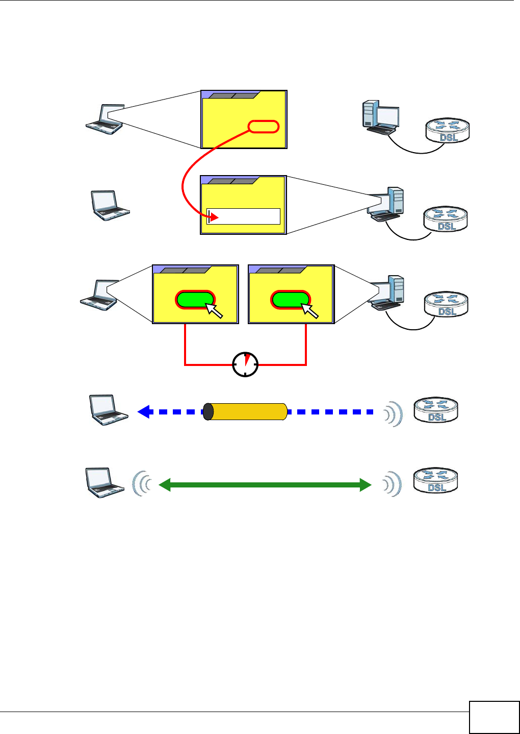
Chapter 6 Wireless
VMG8324-B10A / VMG8324-B30A Series User’s Guide 101
The following figure show s a WPS- enabled wireless client ( inst alled in a notebook com put er)
connect ing t o t he WPS- enabled AP via the PI N m ethod.
Figure 51 Exam ple WPS Process: PI N Met hod
6.10.9.3 How WPS Works
When t wo WPS- enabled devices connect , each device m ust assum e a specific role. One device act s
as t he registrar ( t he device t hat supplies network and securit y set tings) and the ot her device act s
as the enrollee ( t he device t hat receives net work and securit y set t ings. The registrar creat es a
secure EAP ( Ext ensible Aut hent icat ion Prot ocol) tunnel and sends the net work nam e (SSI D) and the
WPA-PSK or WPA2- PSK pr e- shared key t o t he enr ollee. Whet her WPA-PSK or WPA2- PSK is used
depends on the st andards support ed by t he devices. I f t he registrar is already part of a net work, it
sends t he exist ing inform ation. I f not , it generat es t he SSI D and WPA( 2) - PSK random ly.
ENROLLEE
SECURE EAP TUNNEL
SSID
WPA(2)-PSK
WITHIN 2 MINUTES
COMMUNICATION
This device’s
WPS
Enter WPS PIN
WPS
from other device:
WPS PIN: 123456
WPS
START
WPS
START
REGISTRAR
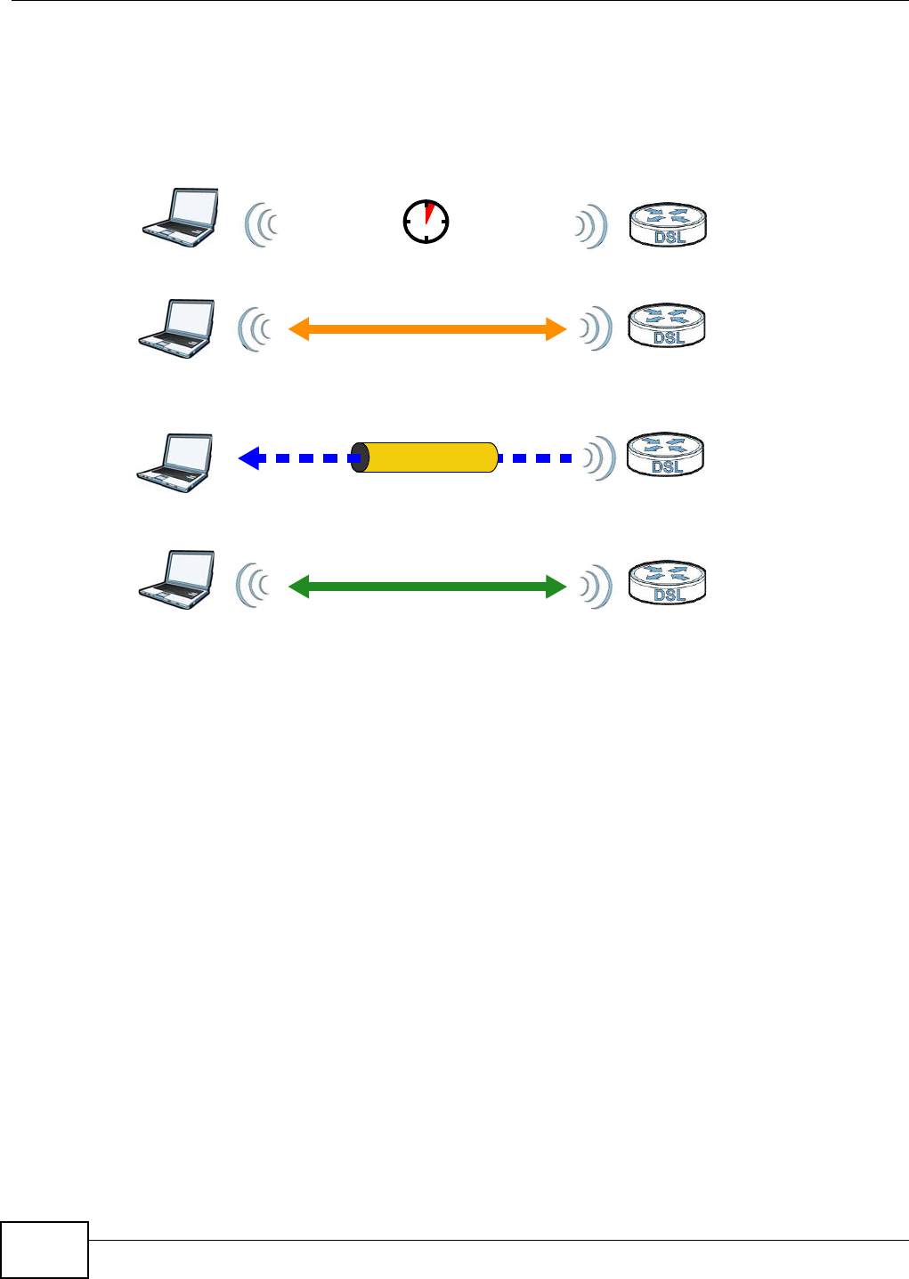
Chapter 6 Wireless
VMG8324-B10A / VMG8324-B30A Series User’s Guide
102
The following figure shows a WPS- enabled client ( installed in a notebook com put er) connect ing t o a
WPS- enabled access point .
Figure 52 How WPS works
The roles of regist rar and enrollee last only as long as t he WPS set up pr ocess is act ive (t wo
m inutes) . The next t im e you use WPS, a different device can be t he regist rar if necessary.
The WPS connect ion process is like a handshake; only t wo devices part icipate in each WPS
transact ion. I f you want t o add m ore devices you should repeat t he process wit h one of t he exist ing
net worked devices and t he new device.
Not e that t he access point ( AP) is not always t he regist rar, and t he wireless client is not always t he
enrollee. All WPS- cert ified APs can be a regist rar, and so can som e WPS- enabled wireless client s.
By default, a WPS devices is “ unconfigured”. This m eans t hat it is not part of an exist ing net work
and can act as eit her enrollee or regist rar ( if it support s bot h funct ions) . I f t he registrar is
unconfigured, t he security set t ings it t ransm its to the enrollee are random ly- generated. Once a
WPS- enabled device has connected t o another device using WPS, it becom es “ configured”. A
configured wireless client can st ill act as enrollee or regist rar in subsequent WPS connections, but a
configured access point can no longer act as enrollee. I t will be t he regist rar in all subsequent WPS
connect ions in which it is involved. I f you want a configur ed AP to act as an enrollee, you m ust reset
it t o it s factory default s.
6.10.9.4 Example WPS Network Setup
This sect ion shows how security set t ings are dist ributed in an exam ple WPS set up.
The following figure shows an exam ple net work. I n step 1, bot h AP1 and Clie n t 1 are
unconfigured. When WPS is activat ed on both, they perform t he handshake. I n t his exam ple, AP1
SECURE TUNNEL
SECURITY INFO
WITHIN 2 MINUTES
COMMUNICATION
ACTIVATE
WPS
ACTIVATE
WPS
WPS HANDSHAKE
REGISTRARENROLLEE
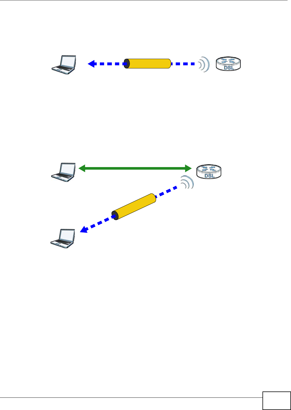
Chapter 6 Wireless
VMG8324-B10A / VMG8324-B30A Series User’s Guide 103
is t he registrar, and Clie nt 1 is t he enrollee. The regist rar random ly generates t he securit y
inform ation t o set up t he net work, since it is unconfigured and has no exist ing inform ation.
Figure 53 WPS: Exam ple Net work St ep 1
I n st ep 2 , you add anot her wireless client t o the net w ork. You know t hat Clie n t 1 supports regist rar
m ode, but it is bet t er t o use AP1 for t he WPS handshake wit h t he new client since you m ust
connect t o t he access point anyway in order t o use t he network. I n t his case, AP1 m ust be t he
registrar, since it is configured (it already has secur ity inform ation for the net w ork) . AP1 supplies
the existing security inform ation t o Client 2 .
Figure 54 WPS: Exam ple Net work St ep 2
REGISTRARENROLLEE
SECURITY INFO
CLIENT 1 AP1
REGISTRAR
CLIENT 1 AP1
ENROLLEE
CLIENT 2
EXISTING CONNECTION
SECURITY INFO
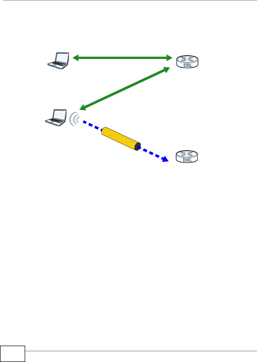
Chapter 6 Wireless
VMG8324-B10A / VMG8324-B30A Series User’s Guide
104
I n st ep 3, you add anot her access point ( AP2 ) t o your net w ork. AP2 is out of range of AP1 , so you
cannot use AP1 for t he WPS handshake wit h t he new access point . However, you know t hat Client
2 supports the registrar funct ion, so you use it t o perform the WPS handshake inst ead.
Figure 55 WPS: Exam ple Net work St ep 3
6.10.9.5 Limitations of WPS
WPS has som e lim itations of w hich you should be aware.
• WPS works in I nfrastructure net works only ( where an AP and a w ireless client com m unicate) . I t
does not work in Ad- Hoc net w orks ( wher e there is no AP) .
• When you use WPS, it works bet ween two devices only. You cannot enr oll m ult iple devices
sim ult aneously, you m ust enroll one aft er t he ot her.
For instance, if you have t wo enrollees and one regist rar you m ust set up t he first enrollee ( by
pressing the WPS butt on on t he regist rar and t he first enrollee, for exam ple) , t hen check that it
successfully enrolled, t hen set up t he second device in t he sam e way.
• WPS works only with ot her WPS- enabled devices. However, you can still add non-WPS devices t o
a network you already set up using WPS.
WPS works by autom at ically issuing a random ly- generat ed WPA- PSK or WPA2- PSK pre- shared
key from t he registrar device to t he enrollee devices. Whet her t he network uses WPA-PSK or
WPA2- PSK depends on the device. You can check the configurat ion interface of t he regist rar
device t o discover t he key t he net work is using ( if the device supports t his feat ure) . Then, you
can ent er t he key int o t he non-WPS device and j oin t he net work as nor m al ( t he non-WPS device
m ust also support WPA- PSK or WPA2- PSK) .
CLIENT 1 AP1
REGISTRAR
CLIENT 2
EXISTING CONNECTION
SECURITY INFO
ENROLLEE
AP2
EXISTING CONNECTION

Chapter 6 Wireless
VMG8324-B10A / VMG8324-B30A Series User’s Guide 105
• When you use the PBC m et hod, t here is a short period ( from the m om ent you press t he but t on
on one device t o the m om ent you press t he but t on on t he other device) w hen any WPS- enabled
device could j oin t he net work. This is because t he regist rar has no way of identifying t he
“ correct ” enrollee, and cannot differentiat e between your enrollee and a rogue device. This is a
possible way for a hacker t o gain access t o a network.
You can easily check t o see if t his has happened. WPS works between only t wo devices
sim ult aneously, so if anot her device has enrolled your device will be unable t o enroll, and will not
have access t o t he net w ork. I f t his happens, open the access point ’s configuration int erface and
look at t he list of associat ed clients ( usually displayed by MAC address) . I t does not m att er if t he
access point is t he WPS regist rar, t he enrollee, or was not involved in the WPS handshake; a
rogue device m ust st ill associate with t he access point to gain access to the net work. Check t he
MAC addresses of your wireless client s ( usually printed on a label on the bot t om of the device) . I f
there is an unknown MAC address you can rem ove it or reset t he AP.

Chapter 6 Wireless
VMG8324-B10A / VMG8324-B30A Series User’s Guide
106
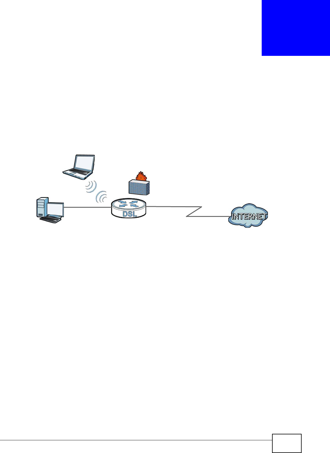
VMG8324-B10A / VMG8324-B30A Series User’s Guide 107
CHAPTER 7
Home Networking
7.1 Overview
A Local Area Net work ( LAN) is a shared com m unication syst em t o which m any net working devices
are connect ed. I t is usually locat ed in one im m ediate area such as a building or floor of a building.
Use t he LAN screens t o help you configure a LAN DHCP server and m anage I P addresses.
7.1.1 What You Can Do in this Chapter
• Use the LAN Se t u p screen t o set t he LAN I P address, subnet m ask, and DHCP set t ings of your
Device ( Sect ion 7.2 on page 109) .
• Use the Sta t ic DHCP screen to assign I P addresses on t he LAN t o specific individual com puters
based on t heir MAC Addresses ( Sect ion 7.3 on page 113) .
• Use the UPnP screen to enable UPnP and UPnP NAT t raversal on t he Device (Sect ion 7.4 on page
114) .
• Use the Addit ional Subn e t screen t o configure I P alias and public st at ic I P (Section 7.5 on page
115) .
• Use the STB Ve n dor I D screen to have t he Device aut om at ically creat e st atic DHCP entries for
Set Top Box ( STB) devices when they request I P addresses (Sect ion 7.8 on page 125)
• Use the 5 t h Et hernet Port screen t o configure t he W AN port as t he Ethernet WAN port or a LAN
port ( Section 7.10 on page 126) .
• Use the LAN VLAN screen to cont r ol t he VLAN I D and I EEE 802.1p priorit y t ags of t raffic sent out
through individual LAN port s ( Section 7.10 on page 126) .
• Use the W ak e on La n screen t o r em ot ely t urn on a device on t he net work. ( Sect ion 7.10 on
page 126) .
DSL
LAN

Chapter 7 Home Networking
VMG8324-B10A / VMG8324-B30A Series User’s Guide
108
7.1.2 What You Need To Know
7.1.2.1 About LAN
IP Address
I P addresses identify individual devices on a net work. Ever y net working device (including
com put ers, servers, routers, print ers, etc.) needs an I P address t o com m unicat e across t he
net work. These net working devices ar e also known as host s.
Subnet Mask
Subnet m asks det erm ine t he m axim um num ber of possible host s on a network. You can also use
subnet m asks t o divide one network into m ultiple sub- net works.
DHCP
A DHCP ( Dynam ic Host Configuration Protocol) server can assign your Device an I P address, subnet
m ask, DNS and ot her routing inform at ion when it 's turned on.
DNS
DNS (Dom ain Nam e Syst em ) is for m apping a dom ain nam e to it s corresponding I P address and
vice versa. The DNS server is ext rem ely im port ant because wit hout it , you m ust know the I P
address of a net w orking device before you can access it.
RADVD (Router Advertisement Daemon)
When an I Pv6 host sends a Router Solicitat ion ( RS) request to discover t he available rout ers,
RADVD wit h Rout er Advert isem ent ( RA) m essages in response to the request . I t specifies t he
m inim um and m axim um intervals of RA broadcast s. RA m essages cont aining the address prefix.
I Pv6 host s can be generated wit h the I Pv6 prefix an I Pv6 address.
7.1.2.2 About UPnP
Identifying UPnP Devices
UPnP hardware is ident ified as an icon in t he Net work Connect ions folder ( Windows XP) . Each UPnP
com pat ible device installed on your net work will appear as a separat e icon. Selecting t he icon of a
UPnP device will allow you to access the inform at ion and properties of t hat device.
NAT Traversal
UPnP NAT t raversal aut om at es the process of allowing an application t o operat e t hrough NAT. UPnP
net work devices can aut om at ically configure net work addressing, announce their presence in the
net work t o other UPnP devices and enable exchange of sim ple product and ser vice descript ions.
NAT t raversal allows t he following:
• Dynam ic port m apping
• Learning public I P addresses

Chapter 7 Home Networking
VMG8324-B10A / VMG8324-B30A Series User’s Guide 109
• Assigning lease t im es to m appings
Windows Messenger is an exam ple of an applicat ion that support s NAT t raversal and UPnP.
See t he Chapter 10 on page 157 for m ore inform at ion on NAT.
Cautions with UPnP
The aut om at ed nature of NAT t raversal applicat ions in est ablishing their own services and opening
firewall port s m ay present network security issues. Net w ork inform ation and configurat ion m ay also
be obt ained and m odified by users in som e net work environm ents.
When a UPnP device j oins a net work, it announces its presence wit h a m ult icast m essage. For
security reasons, t he Device allows m ulticast m essages on the LAN only.
All UPnP-enabled devices m ay com m unicate freely wit h each ot her wit hout addit ional configurat ion.
Disable UPnP if t his is not your intention.
UPnP and ZyXEL
ZyXEL has achieved UPnP cer t ificat ion from t he Universal Plug and Play Forum UPnP™
I m plem enters Corp. (UI C). ZyXEL's UPnP im plem ent at ion support s I nternet Gat eway Device ( I GD)
1.0.
See Sect ion 7.5 on page 115 for exam ples of inst alling and using UPnP.
Finding Out More
See Sect ion 7.12 on page 128 for t echnical background inform ation on LANs.
7.1.3 Before You Begin
Find out t he MAC addresses of your network devices if you intend t o add them t o t he DHCP Client
List screen.
7.2 The LAN Setup Screen
Use t his screen t o set t he Local Area Net w ork I P address and subnet m ask of your Device. Click
N e t w ork Se t t ing > Hom e N e t w or king to open the LAN Set u p screen.
Follow t hese st eps to configure your LAN sett ings.
1Ent er an I P address into the I P Address field. The I P address m ust be in dot ted decim al notat ion.
This will becom e t he I P address of your Device.
2Ent er t he I P subnet m ask int o t he I P Subn e t M ask field. Unless inst ruct ed otherwise it is best t o
leave t his alone, t he configurat or will aut om at ically com put e a subnet m ask based upon t he I P
address you ent ered.
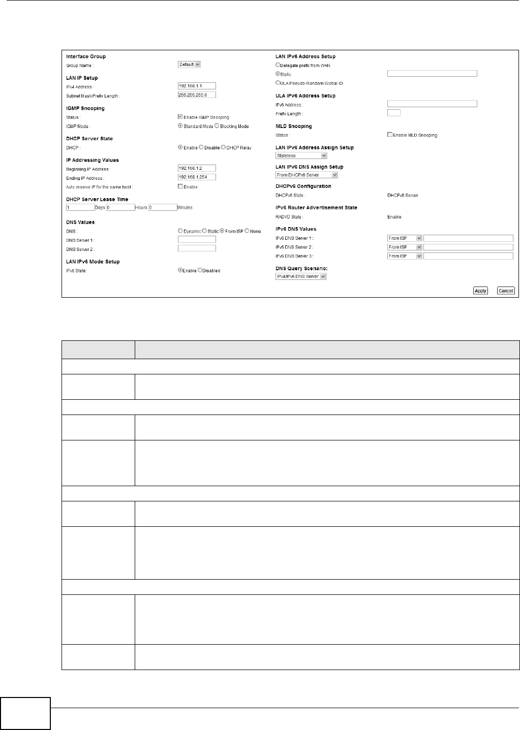
Chapter 7 Home Networking
VMG8324-B10A / VMG8324-B30A Series User’s Guide
110
3Click Apply t o save your sett ings.
Figure 56 Net work Set t ing > Hom e Net w orking > LAN Set up
The following t able describes t he fields in t his screen.
Table 31 Net work Sett ing > Hom e Net w orking > LAN Set up
LABEL DESCRIPTION
I nterface Group
Group Nam e Select t he int erface group nam e for which you want t o configure LAN set t ings. See Chapter
12 on page 179 for how t o create a new int erface group.
LAN I P Set up
I Pv4 Addr ess Ent er t he LAN I Pv4 I P addr ess you w ant t o assig n t o y our Dev i ce in dot t ed decim al not at ion,
for exam ple, 192.168.1.1 ( fact ory default ) .
Subnet Mask/
Prefix Lengt h
Type t he subnet m ask of your net work in dot t ed decim al notat ion, for exam ple
255.255.255.0 ( fact ory default ) . Your Device aut om at ically com putes t he subnet m ask
based on t he I P Address you ent er, so do not change this field unless you are instruct ed to
do so.
I GMP Snooping
St at us Select t he En able I GM P Snooping checkbox t o allow s t he Device to passively learn
m ult icast group.
I GMP Mode Select St a ndard Mode t o have t he Device forwar d m ulticast packet s t o a port t hat j oins the
m ulticast group and broadcast unknown m ult icast packets from t he WAN to all LAN ports.
Select Block ing M ode t o have t he Device block all unknown m ulticast packet s from t he
WAN.
DHCP Server St ate
DHCP Select Enable t o have the Device act as a DHCP server or DHCP relay agent.
Select D isa ble t o stop the DHCP server on t he Device.
Select D HCP Re lay to have t he Device forward DHCP request t o the DHCP server.
DHCP Relay
Ser ver Address
This field is only available when you select DHCP Relay in the D H CP field.

Chapter 7 Home Networking
VMG8324-B10A / VMG8324-B30A Series User’s Guide 111
I Pv4 Addr ess Ent er t he I Pv4 I P addr ess of t he act ual rem ote DHCP server in t his field.
I P Addressing
Va lu e s
This field is only available when you select En a ble in t he D H CP field.
Beginning I P
Address
This field specifies t he first of t he cont iguous addresses in t he I P address pool.
Ending I P
Address
This field specifies the last of t he contiguous addresses in t he I P address pool.
Aut o reserve I P
for t he sam e
host
Select Enable t o have t he Device r ecor d DHCP I P addresses wit h the MAC addr esses t he I P
addr esses ar e assigned t o. The Device assigns t he sam e I P address to t he sam e MAC
addr ess when the host requests an I P address again t hrough DHCP.
DHCP Server
Lease Tim e
This is the per iod of t im e DHCP- assigned addresses is used. DHCP aut om at ically assigns I P
addr esses to client s when t hey log in. DHCP cent ralizes I P address m anagem ent on cent ral
com put ers t hat r un t he DHCP ser ver program . DHCP leases addresses, for a period of tim e,
which m eans t hat past addr esses are “ recycled” and m ade available for futur e reassignm ent
to other syst em s.
This field is only available when you select En a ble in t he D H CP field.
Days/ Hours/
Minut es
Ent er t he lease t im e of t he DHCP server.
DNS Values This field is only available when you select Enable in the DH CP field.
DNS Select t he t ype of service t hat you are registered for from your Dynam ic DNS service
provider.
Select D ynam ic if you have t he Dynam ic DNS service.
Select St a t ic if you have the St at ic DNS service.
DNS Server 1
DNS Server 2
Ent er t he first and second DNS ( Dom ain Nam e Syst em ) server I P address t he Device passes
to t he DHCP client s.
LAN I Pv6 Mode Setup
I Pv6 State Select Ena ble to act ivat e the I Pv6 m ode and configur e I Pv6 settings on t he Device.
LAN I Pv6 Address Set up
Delegat e prefix
from WAN
Select t his opt ion to aut om at ically obtain an I Pv6 net work pr efix from the service pr ovider
or an uplink rout er.
St atic Select this opt ion t o configure a fixed I Pv6 address for the Device’s LAN I Pv 6 address.
ULA Pseudo-
Random Global
I D
A unique local addr ess ( ULA) is a unique I Pv6 address for use in privat e net works but not
rout able in t he global I Pv6 I nternet .
Select this t o have t he Dev ice autom at ically generate a globally unique address for the LAN
I Pv6 address. The address form at is like fdxx : x xxx: xxxx: xxxx: : / 64.
ULA I Pv6 Address Set up
I Pv6 Address I f you select st atic I Pv6 address, ent er t he I Pv6 address prefix t hat t he Device uses for t he
LAN I Pv6 address.
Prefix Lengt h I f you select st at ic I Pv6 address, ent er the I Pv6 prefix lengt h that the Dev ice uses t o
generat e t he LAN I Pv6 address.
An I Pv6 prefix lengt h specifies how m any m ost significant bit s (st art ing from t he left ) in t he
addr ess com pose the net work address. This field displays t he bit num ber of the I Pv6 subnet
m ask.
Table 31 Net work Sett ing > Hom e Net working > LAN Set up ( cont inued)
LABEL DESCRIPTION

Chapter 7 Home Networking
VMG8324-B10A / VMG8324-B30A Series User’s Guide
112
MLD Snooping Mult icast List ener Discov ery ( MLD) allows an I Pv6 swit ch or rout er t o discover the presence
of MLD host s who wish t o receive m ulticast packets and t he I P addresses of m ult icast
groups the host s want to join on it s net work. Select Ena ble MLD Snoopin g t o activat e MLD
Snooping on t he Device. This allows the Device t o check MLD packet s passing t hr ough it and
learn t he m ult icast gr oup m em bership. I t helps reduce m ulticast t raffic.
MLD Mode Select St a ndard Mode to have t he Device forward I Pv6 m ulticast packet s t o a port t hat
joins t he I Pv6 m ulticast group and broadcast unknown I Pv6 m ulticast packets from t he WAN
to all LAN port s.
Select Block ing M ode t o have t he Device block all unknown I Pv6 m ulticast packet s fr om
the WAN.
LAN I Pv6
Address Assign
Set up
Select how you want t o obt ain an I Pv6 address:
•St a t e le ss: The Device uses I Pv6 st at eless aut oconfigurat ion. RADVD ( Rout er
Advert isem ent Daem on) is enabled to have the Device send I Pv6 prefix inform at ion in
rout er advertisem ent s periodically and in response t o rout er solicit ations. DHCPv6 server
is disabled.
•St a t e fu l: The Dev ice uses I Pv6 stat eful aut oconfigurat ion. The DHCPv6 server is
enabled t o have the Device act as a DHCPv6 ser ver and pass I Pv6 addresses t o DHCPv6
client s.
•St a t e less a nd Stat eful: The Dev ice uses bot h I Pv6 stat eless and st ateful
aut oconfigurat ion. The LAN I Pv6 client s can obt ain I Pv6 addresses eit her through rout er
advert isem ent s or t hrough DHCPv6.
•
LAN I Pv6 DNS
Assign Setup
Select how t he Dev ice provide DNS ser ver and dom ain nam e inform ation t o t he client s:
•From Rou t e r Adve rt isem e nt : The Device provides DNS inform at ion through rout er
advert isem ent s.
•From DH CPv6 Se r v er: The Device prov ides DNS inform at ion thr ough DHCPv6.
•Fr o m RA & D H CPv 6 Se r v e r : The Dev ice prov ides DNS inform at ion t hr ough bot h rout er
advert isem ent s and DHCPv6.
DHCPv6 Configuration
DHCPv6 St at e This show s the st at us of t he DHCPv6.
I Pv6 Rout er Adv ert isem ent St at e
RADVD State This show s whet her RADVD is enabled or not .
I Pv6 DNS Values
I Pv6 DNS
Server 1- 3
Select Fr om I SP if your I SP dynam ically assigns I Pv6 DNS ser ver inform at ion.
Select Use r- D e fine d if you have t he I Pv6 address of a DNS server. Ent er t he DNS server
I Pv6 addresses t he Device passes t o t he DHCP clients.
Select N on e if you do not want t o configure I Pv6 DNS servers.
DNS Query
Scenario
Select how t he Device handles client s’ DNS inform ation requests.
•I Pv4 / I Pv6 DN S Ser ve r: The Device forwards t he requests t o bot h the I Pv4 and I Pv6
DNS servers and sends client s t he first DNS infor m ation it receives.
•I Pv6 DNS Se r ver On ly: The Device forwards the request s to the I Pv6 DNS server and
sends client s t he DNS inform at ion it receives.
•I Pv4 DNS Se r ver On ly: The Device forwards the request s to the I Pv4 DNS server and
sends client s t he DNS infor m at ion it receives.
•I Pv6 DN S Serv er First : The Device forwar ds t he requests t o t he I Pv6 DNS server first
and then the I Pv4 DNS server. Then it sends client s the first DNS infor m at ion it receives.
•I Pv4 DN S Serv er First : The Device forwar ds t he requests t o t he I Pv4 DNS server first
and then the I Pv6 DNS server. Then it sends client s the first DNS infor m at ion it receives.
Apply Click Apply t o save your changes.
Cancel Click Ca ncel t o restore your previously saved set t ings.
Table 31 Net work Sett ing > Hom e Net working > LAN Set up ( cont inued)
LABEL DESCRIPTION
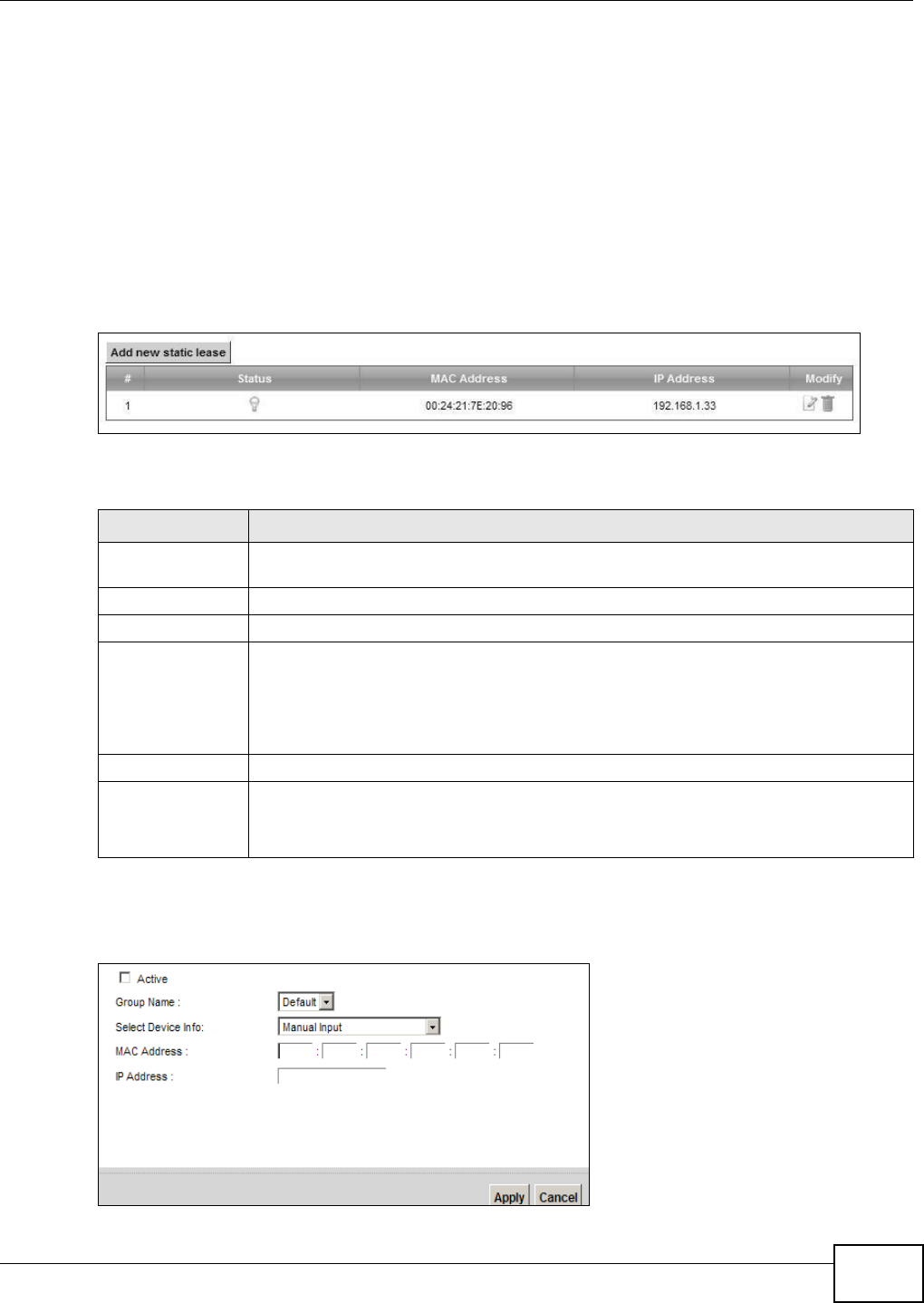
Chapter 7 Home Networking
VMG8324-B10A / VMG8324-B30A Series User’s Guide 113
7.3 The Static DHCP Screen
This t able allows you to assign I P addresses on t he LAN t o specific individual com put er s based on
their MAC Addresses.
Every Ethernet device has a unique MAC (Media Access Control) address. The MAC address is
assigned at t he fact ory and consist s of six pair s of hexadecim al charact ers, for exam ple,
00: A0: C5: 00: 00: 02.
Use t his screen t o change your Device’s st at ic DHCP set t ings. Click N et w ork Set t ing > Hom e
N e t w o rk in g > St at ic DHCP t o open the following screen.
Figure 57 Net work Set t ing > Hom e Net w orking > St at ic DHCP
The following t able describes t he labels in this screen.
I f you click Add new st a t ic le ase in the Sta t ic DHCP screen or t he Edit icon next t o a static DHCP
ent ry, t he follow ing screen displays.
Figure 58 St at ic DHCP: Add/ Edit
Table 32 Net work Sett ing > Hom e Networking > Stat ic DHCP
LABEL DESCRIPTION
Add new stat ic
lease
Click this to add a new st atic DHCP ent ry.
# This is the index num ber of the ent r y.
St atus This field displays whether t he client is connect ed to t he Device.
MAC Address The MAC ( Media Access Cont rol) or Ethernet address on a LAN ( Local Area Net work) is
unique t o your com puter (six pairs of hex adecim al not ation).
A net work interface card such as an Ethernet adapter has a hardwired address t hat is
assigned at t he fact ory. This address follows an indust ry st andard t hat ensures no ot her
adapter has a sim ilar address.
I P Address This field displays the I P address relative to the # field listed above.
Modify Click t he Edit icon to have t he I P address field edit able and change it .
Click the D ele t e icon t o delet e a stat ic DHCP ent ry. A window displays asking you t o
confirm t hat you want to delet e the selected ent ry.
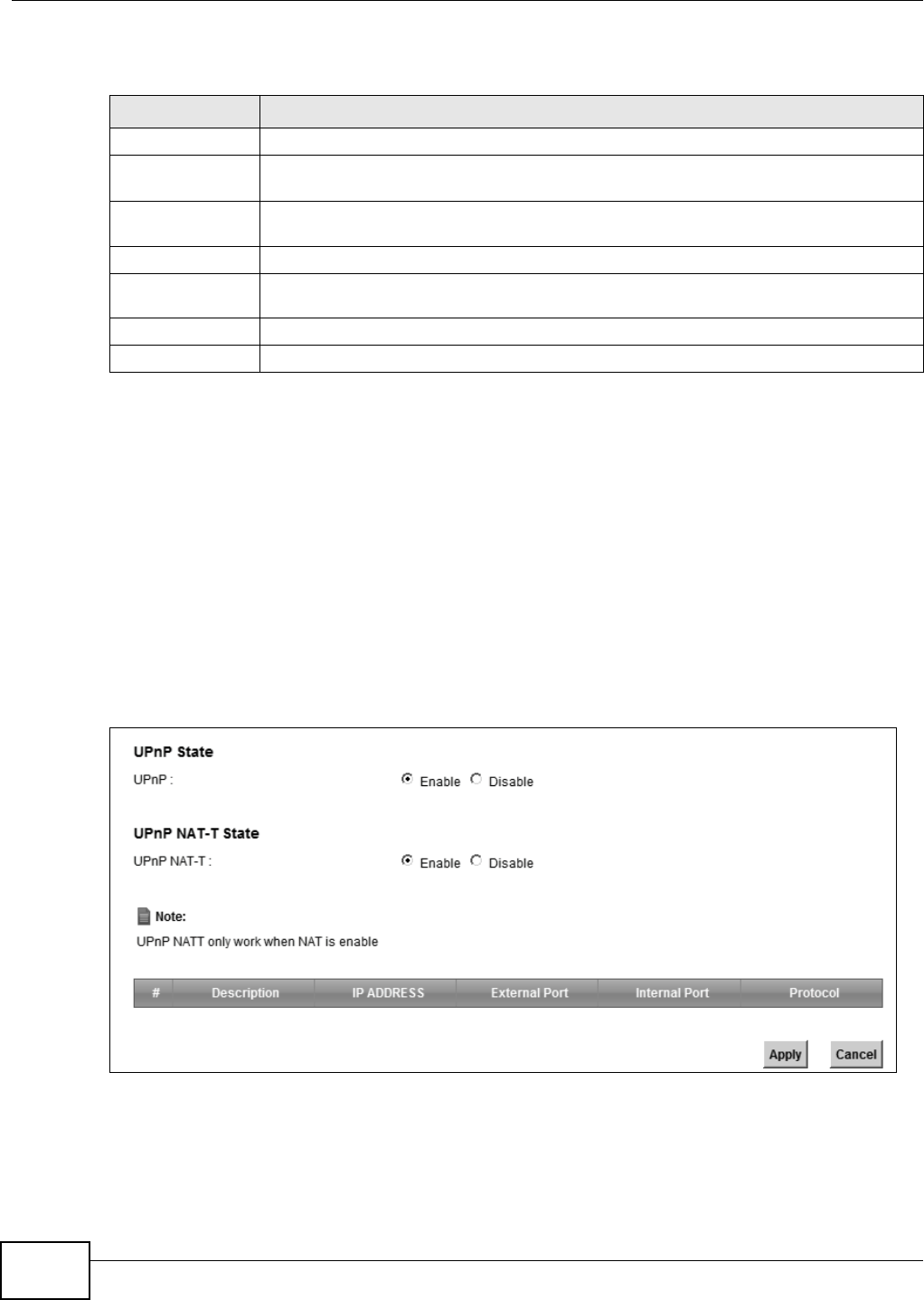
Chapter 7 Home Networking
VMG8324-B10A / VMG8324-B30A Series User’s Guide
114
The following t able describes t he labels in this screen.
7.4 The UPnP Screen
Universal Plug and Play ( UPnP) is a distribut ed, open net w orking standard that uses TCP/ I P for
sim ple peer-t o- peer net w ork connect ivity between devices. A UPnP device can dynam ically j oin a
net work, obt ain an I P address, convey it s capabilit ies and learn about ot her devices on t he net w ork.
I n t urn, a device can leave a net work sm oothly and aut om at ically when it is no longer in use.
See page 108 for m ore inform ation on UPnP.
Use t he following screen t o configure t he UPnP sett ings on your Device. Click N et w ork Set t ing >
Hom e N e t w orking > UPn P t o display the screen shown next .
Figure 59 Net work Set t ing > Hom e Net w orking > UPnP
Table 33 St atic DHCP: Add/ Edit
LABEL DESCRIPTION
Act iv e Select t his t o act ivat e t he connect ion bet ween t he client and the Device.
Group Nam e Select the interface group nam e for which you w ant t o configur e st at ic DHCP settings.
See Chapt er 12 on page 179 for how t o creat e a new int erface group.
Select Device I nfo Select a device or com puter fr om the drop-down list or select Manu a l I n pu t t o m anually
enter a device’s MAC address and I P address in t he following fields.
MAC Address I f you select M a n ua l I npu t , ent er the MAC address of a com puter on your LAN.
I P Address I f you select M a nua l I npu t , enter t he I P address that you want to assign to the
com put er on your LAN w it h the MAC address t hat you will also specify.
Apply Click Apply t o save your changes.
Cancel Click Ca ncel t o exit this screen wit hout saving.

Chapter 7 Home Networking
VMG8324-B10A / VMG8324-B30A Series User’s Guide 115
The following t able describes t he labels in this screen.
7.5 Installing UPnP in Windows Example
This sect ion shows how t o inst all UPnP in Windows Me and Windows XP.
Installing UPnP in Windows Me
Follow t he steps below t o install t he UPnP in Windows Me.
1Click St a rt and Cont rol Pa n e l. Double- click Add/ Re m ove Progra m s.
Table 34 Net work Sett ing > Hom e Net working > UPnP
LABEL DESCRIPTION
UPnP Select Ena ble t o act ivate UPnP. Be aware t hat anyone could use a UPnP applicat ion to open
the web configurator's login screen w it hout ent ering t he Device's I P address (alt hough you
m ust st ill ent er the password t o access t he web configurator) .
UPnP NAT-T Select En a ble t o allow UPnP- enabled applicat ions to aut om at ically configure t he Device so
that t hey can com m unicat e t hrough t he Device by using NAT t raversal. UPnP applicat ions
aut om at ically reser ve a NAT forwarding port in order t o com m unicate wit h another UPnP
enabled device; t his elim inat es t he need t o m anually configure port forwarding for t he UPnP
enabled applicat ion.
The table below displays the NAT port forwarding rules added autom at ically by UPnP NAT-T.
# This is t he index num ber of the UPnP NAT-T connect ion.
Descript ion This is t he description of t he UPnP NAT-T connect ion.
I P Address This is the I P addr ess of t he ot her connect ed UPnP enabled device.
Ext ernal Port This is t he ext ernal port num ber t hat ident ifies t he service.
I nternal Port This is t he int ernal port num ber t hat ident ifies t he service.
Apply Click Apply to save your changes.
Cancel Click Ca nce l to exit t his screen without saving.
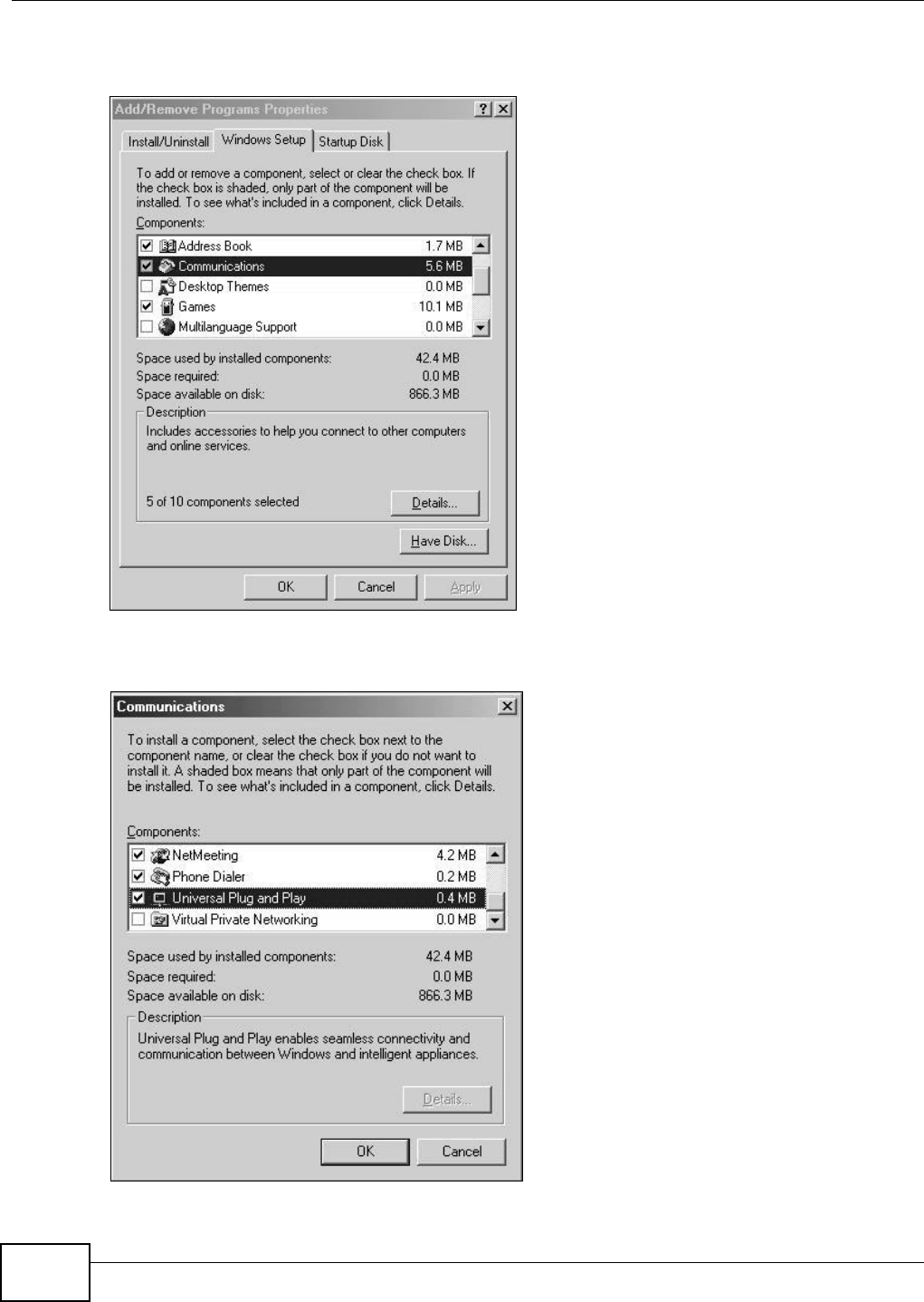
Chapter 7 Home Networking
VMG8324-B10A / VMG8324-B30A Series User’s Guide
116
2Click on the W indow s Set up tab and select Com m u nica t ion in t he Com ponent s select ion box.
Click D e t a ils.
Add/Remove Programs: Windows Setup: Communication
3I n t he Com m unicat ions window, select t he Unive rsa l Plug and Pla y check box in t he
Com p on e nt s select ion box.
Add/Remove Programs: Windows Setup: Communication: Components
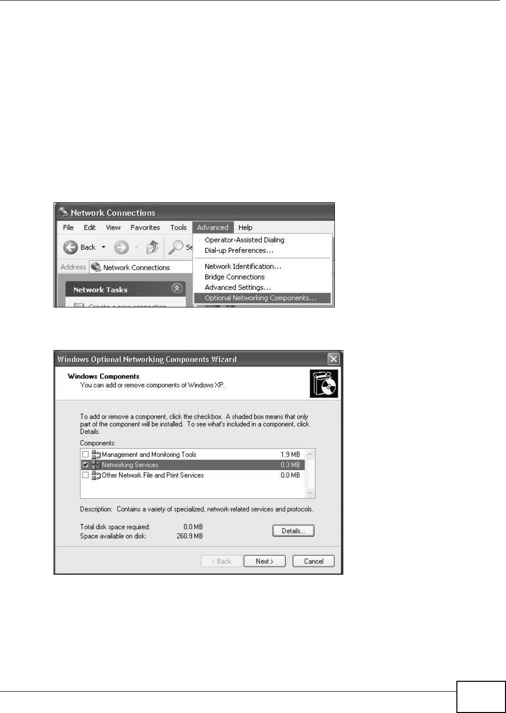
Chapter 7 Home Networking
VMG8324-B10A / VMG8324-B30A Series User’s Guide 117
4Click OK to go back to the Add/ Rem ove Program s Pr oper t ies window and click N e x t.
5Rest art t he com put er when prom pt ed.
Installing UPnP in Windows XP
Follow t he steps below t o inst all the UPnP in Windows XP.
1Click St a r t and Con t r ol Pa n e l.
2Double-click N et w or k Connect ions.
3I n t he N e t w or k Con n e ct ions window, click Advanced in t he m ain m enu and select Opt ion a l
N e t w orking Com pone n t s ….
Network Co nnections
4The W indow s Opt ional N e t w or k ing Com ponent s W iza r d window displays. Select N et w or k ing
Se r v ice in the Com pone n t s selection box and click D et a ils.
Windows Optional Networking Components Wizard
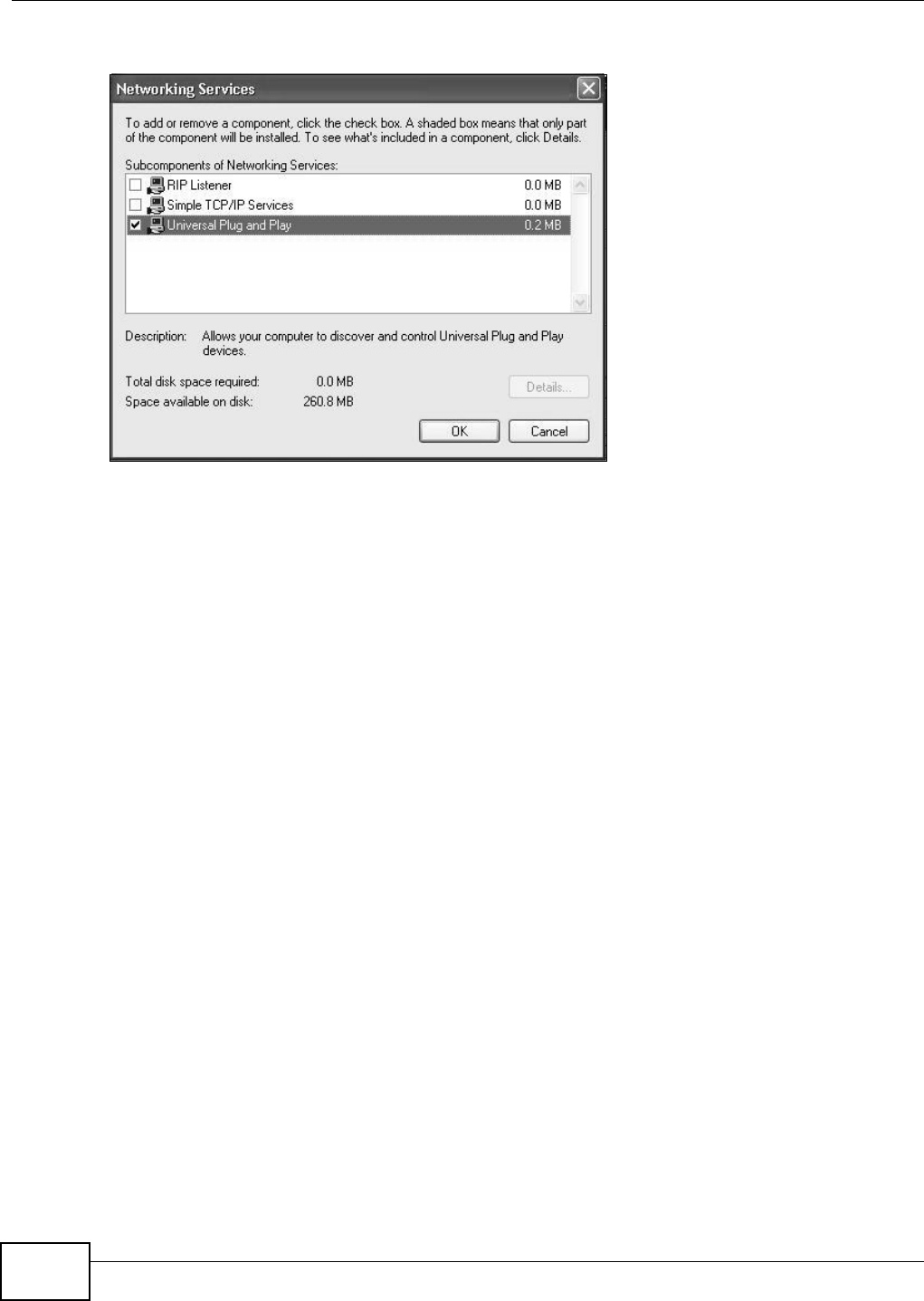
Chapter 7 Home Networking
VMG8324-B10A / VMG8324-B30A Series User’s Guide
118
5I n t he N e t w or k ing Ser vices window, select t he Univ e r sal Plug a n d Pla y check box.
Networking Services
6Click OK to go back t o t he W indow s Opt ion a l N e t w or k ing Com pon e nt W iza rd window and
click N e x t .
7.6 Using UPnP in Windows XP Example
This sect ion shows you how t o use t he UPnP feat ure in Windows XP. You m ust already have UPnP
inst alled in Windows XP and UPnP activat ed on the Device.
Make sure t he com puter is connected t o a LAN port of the Device. Turn on your com puter and the
Device.
Auto-discover Your UPnP-enabled Network Device
1Click St a r t and Con t r ol Pa n e l. Double- click N et w ork Con ne ct ions. An icon displays under
I nt ernet Gat eway.
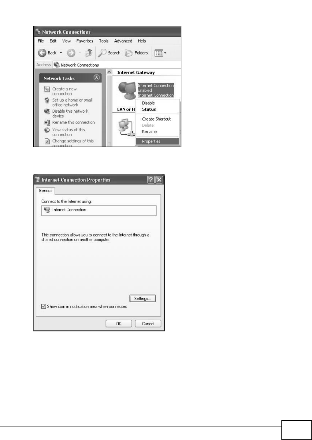
Chapter 7 Home Networking
VMG8324-B10A / VMG8324-B30A Series User’s Guide 119
2Right- click t he icon and select Pr op er t ie s.
Network Co nnections
3I n t he I nt er ne t Conne ct ion Prope rt ies window, click Set t ings to see the port m appings t here
were aut om at ically creat ed.
Internet Connec tion Properties
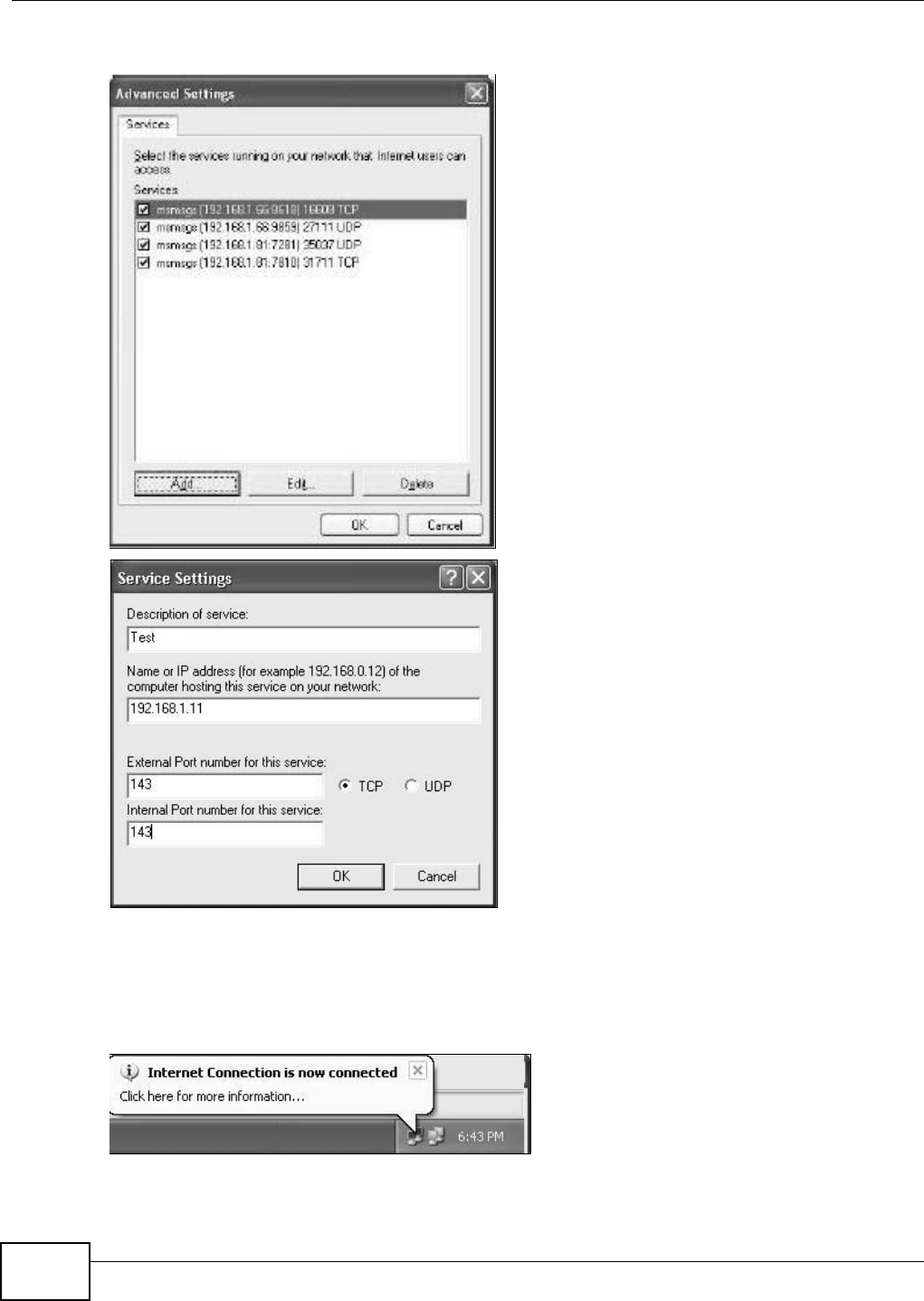
Chapter 7 Home Networking
VMG8324-B10A / VMG8324-B30A Series User’s Guide
120
4You m ay edit or delet e t he port m appings or click Add t o m anually add port m appings.
Internet Connection Properties: Advanced Settings
Internet Connec tion Properties: Ad vanced Settings: Add
5When t he UPnP- enabled device is disconnected from your com put er, all port m appings will be
deleted autom at ically.
6Select Show icon in not ifica t ion ar e a w he n con n e ct e d opt ion and click OK. An icon displays in
the syst em tray.
System Tray Icon
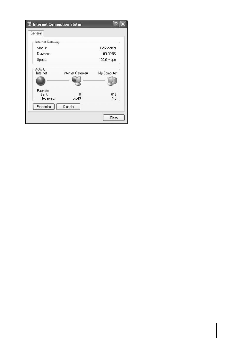
Chapter 7 Home Networking
VMG8324-B10A / VMG8324-B30A Series User’s Guide 121
7Double-click on t he icon t o display your current I nt er net connection st atus.
Internet Conn ection Status
Web Configurator Easy Access
With UPnP, you can access the web-based configurator on t he Device without finding out t he I P
address of t he Device first . This com es helpful if you do not know the I P address of t he Device.
Follow t he st eps below t o access t he web configurat or.
1Click St a r t and t hen Cont r ol Panel.
2Double-click N et w or k Connect ions.
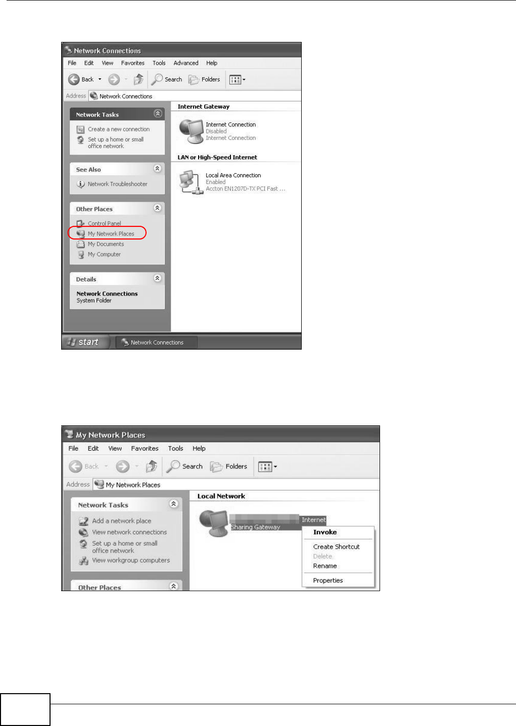
Chapter 7 Home Networking
VMG8324-B10A / VMG8324-B30A Series User’s Guide
122
3Select My N e t w or k Places under Ot h e r Pla ce s.
Network Co nnections
4An icon with the description for each UPnP- enabled device displays under Local N e t w or k .
5Right- click on t he icon for your Device and select I n vo k e. The web configurat or login screen
displays.
Network Co nnections: My Netw ork Places
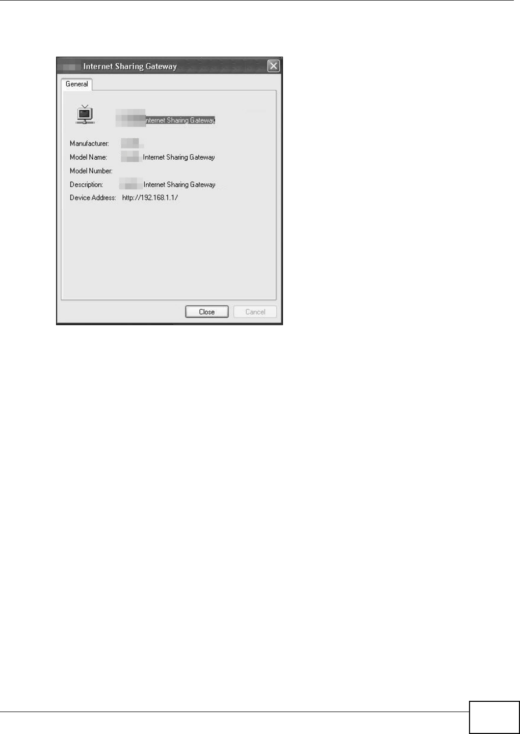
Chapter 7 Home Networking
VMG8324-B10A / VMG8324-B30A Series User’s Guide 123
6Right- click on t he icon for your Device and select Pr ope r t ie s. A propert ies window displays with
basic inform ation about t he Device.
Network Co nnections: My Netw ork Places: Proper ties: Example
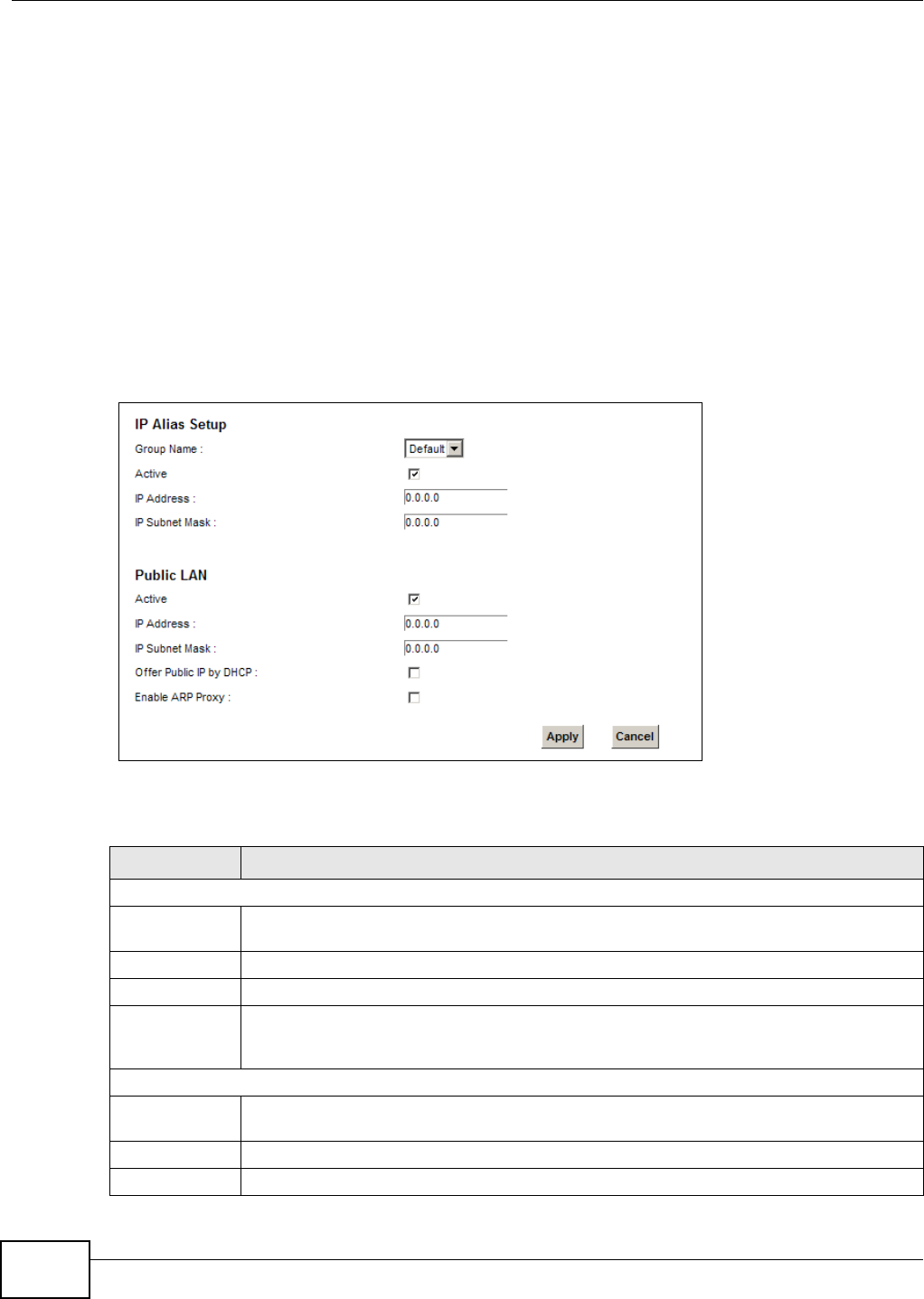
Chapter 7 Home Networking
VMG8324-B10A / VMG8324-B30A Series User’s Guide
124
7.7 The Additional Subnet Screen
Use t he Addit iona l Su bnet screen t o configure I P alias and public st at ic I P.
I P alias allows you to partition a physical network into different logical networks over t he sam e
Et hernet inter face. The Device support s m ult iple logical LAN int erfaces via it s physical Ethernet
int erface w ith the Device it self as t he gat eway for t he LAN net w ork. When you use I P alias, you can
also configure firewall rules t o cont rol access to the LAN's logical network ( subnet) .
I f your I SP provides t he Public LAN service, t he Device m ay use an LAN I P address t hat can be
accessed from t he WAN.
Click N et w ork Se t t ing > H om e Ne t w ork in g > Addit iona l Su bnet t o display t he screen shown
next .
Figure 60 Net work Set t ing > Hom e Net w orking > Addit ional Subnet
The following t able describes t he labels in this screen.
Table 35 Net work Sett ing > Hom e Net w orking > Addit ional Subnet
LABEL DESCRIPTION
I P Alias Set up
Group Nam e Select the int erface group nam e for which you want t o configure the I P alias settings. See
Chapt er 12 on page 179 for how t o create a new interface group.
Act iv e Select t he checkbox t o configure a LAN net work for the Device.
I P Address Ent er the I P address of your Device in dotted decim al not at ion.
I P Subnet Mask Your Device will aut om at ically calculat e t he subnet m ask based on t he I P address that you
assign. Unless you ar e im plem ent ing subnetting, use the subnet m ask com puted by t he
Device.
Public LAN
Active Select t he checkbox t o enable t he Public LAN feat ure. Your I SP m ust suppor t Public LAN and
St at ic I P.
I P Address Enter t he public I P address provided by your I SP.
I P Subnet Mask Enter t he public I P subnet m ask prov ided by your I SP.
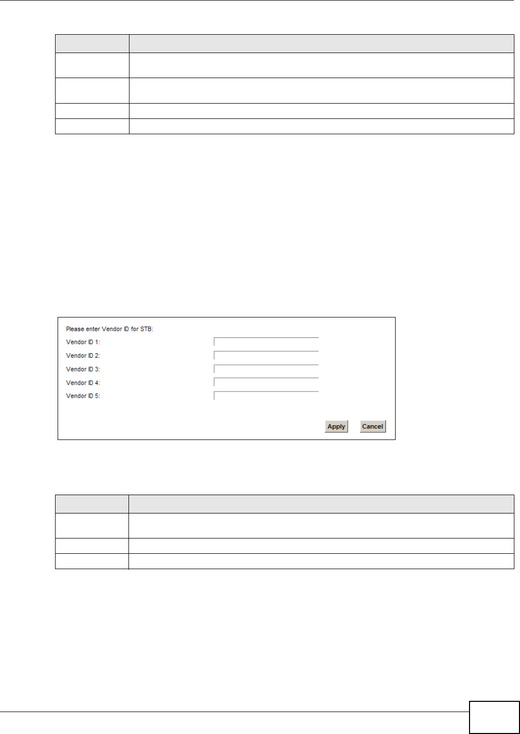
Chapter 7 Home Networking
VMG8324-B10A / VMG8324-B30A Series User’s Guide 125
7.8 The STB Vendor ID Screen
Set Top Box ( STB) devices wit h dynam ic I P addresses som et im es don’t renew t heir I P addresses
befor e the lease tim e expir es. This could lead t o I P address conflict s if t he STB continues t o use an
I P address t hat gets assigned to another device. Use t his screen t o list t he Vendor I Ds of connect ed
STBs to have t he Device aut om at ically creat e st atic DHCP ent ries for t hem when they request I P
addresses.
Click N et w ork Se t t ing > H om e N e t w or k ing > STB V e n dor I D t o open t his screen.
Figure 61 Net work Set t ing > Hom e Net w orking > STB Vendor I D
The following t able describes t he labels in this screen.
7.9 The 5th Ethernet Port Screen
I f you use a DSL connection, you can configur e your Ethernet WAN port as an ext ra LAN por t . This
Gigabit Ethernet port provides fast er t ransm ission speeds. Click N e t w or k Se t t ing > H om e
N e t w o rk in g > 5 t h Et h e r net Por t t o open t his screen.
Offer Public I P
by DHCP
Select the checkbox t o enable t he Device t o provide public I P addresses by DHCP server.
Enable ARP
Prox y
Select the checkbox t o enable the ARP ( Address Resolut ion Pr ot ocol) proxy.
Apply Click Apply t o save your changes.
Cancel Click Ca ncel t o exit this screen w it hout saving.
Table 35 Net work Sett ing > Hom e Net w orking > Addit ional Subnet ( cont inued)
LABEL DESCRIPTION
Table 36 Net work Sett ing > Hom e Net working > STB Vendor I D
LABEL DESCRIPTION
Ven dor I D 1 ~
5
Enter t he STB’s vendor I D.
Apply Click Apply to save your changes.
Cancel Click Ca nce l to exit t his screen without saving.
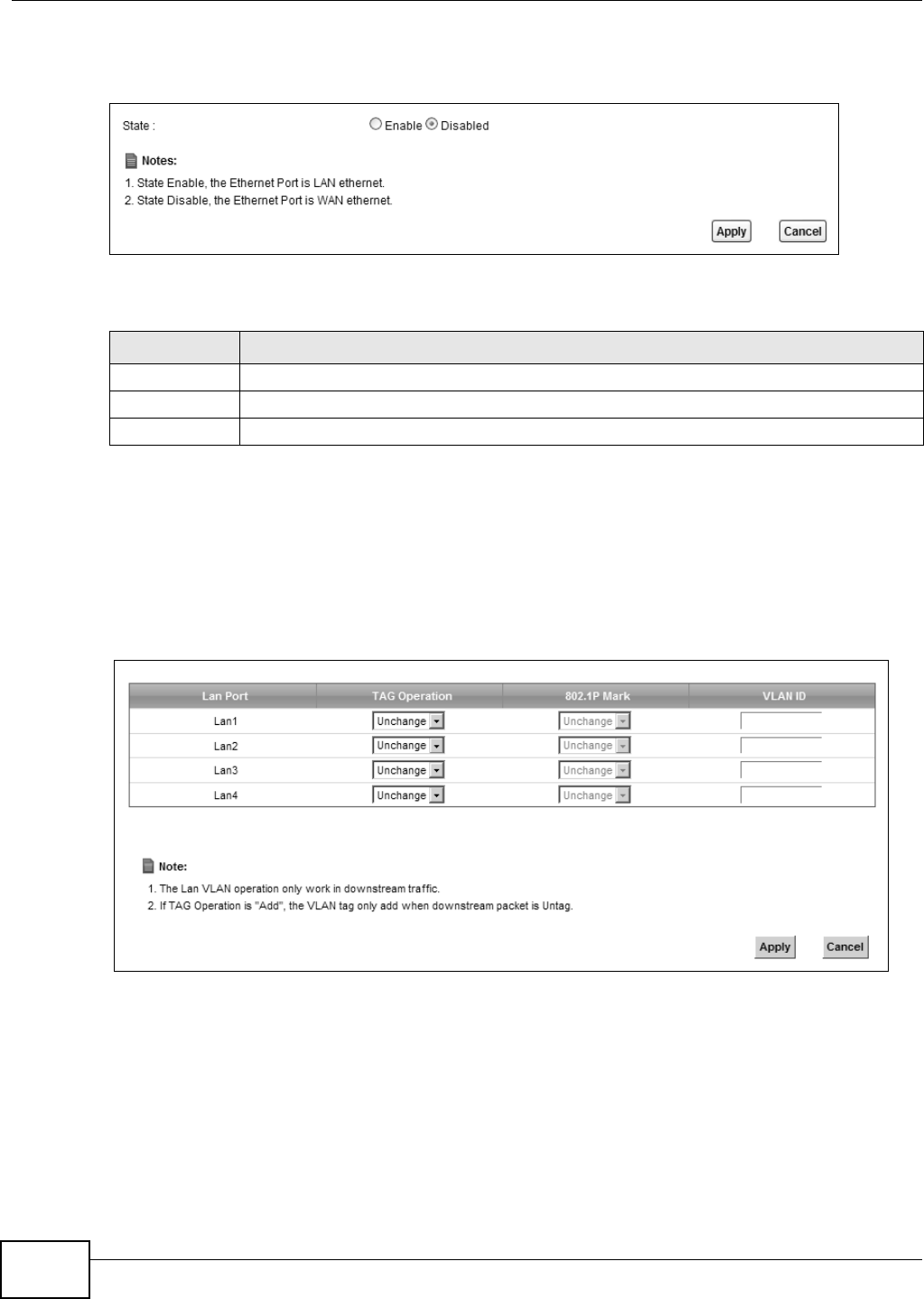
Chapter 7 Home Networking
VMG8324-B10A / VMG8324-B30A Series User’s Guide
126
Not e: The Device needs t o rest art to m ake the role change take effect .
Figure 62 Net work Set t ing > Hom e Net w orking > 5t h Ethernet Port
The following t able describes t he labels in this screen.
7.10 The LAN VLAN Screen
Click N et w ork Set t ing > H om e N e t w or k ing > LAN VLAN t o open this screen. Use t his screen to
cont rol t he VLAN I D and I EEE 802.1p prior ity t ags of t raffic sent out t hrough individual LAN port s.
Figure 63 Net work Set t ing > Hom e Net w orking > LAN VLAN
Table 37 Net work Set t ing > Hom e Net working > 5t h Ethernet Port
LABEL DESCRIPTION
St ate Select Enable to use t he Ether net WAN port as a LAN port on the Device.
Apply Click Apply to save your changes.
Cancel Click Ca nce l to exit t his screen without saving.
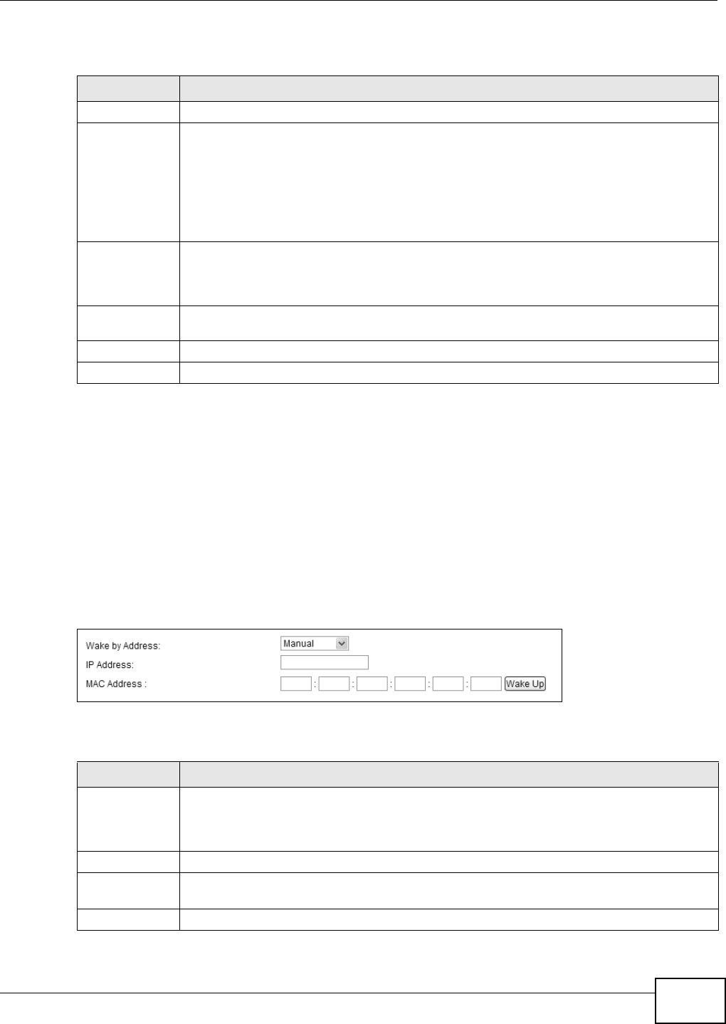
Chapter 7 Home Networking
VMG8324-B10A / VMG8324-B30A Series User’s Guide 127
The following t able describes t he labels in this screen.
7.11 The Wake on LAN Screen
Use t his screen to turn on a device on t he LAN net work. To use t his feature, t he rem ot e device m ust
also support Wake On LAN.
You need t o know t he MAC address of t he LAN device. I t m ay be on a label on t he device or in its
docum ent at ion.
Click N et w ork Se t t ing > H om e N e t w or k ing > W ak e on La n to open this screen.
Figure 64 Net work Set t ing > Hom e Net w orking > Wake on Lan
The following t able describes t he labels in this screen.
Table 38 Net work Sett ing > Hom e Net w orking > LAN VLAN
LABEL DESCRIPTION
Lan Port These represent the Device’s LAN ports.
Tag Operat ion Select what you want the Device t o do t o t he I EEE 802.1q VLAN I D and priorit y tags of
downstream t raffic before sending it out t hrough this LAN port.
•Unch a nge - Don’t do anyt hing t o t he t raffic’s VLAN I D and priorit y tags.
•Add - Add VLAN I D and priority tags t o unt agged traffic.
•Re m ove - Delet e one t ag from t agged traffic. I f the fram e has double t ags, t his rem oves
the outer t ag. This does not affect untagged t raffic.
•Re m a r k - Change t he value of t he outer VLAN I D and priorit y tags.
802.1P Mark Use t his opt ion to set what t o do for t he I EEE 802.1p priorit y t ags when you add or rem ark
the tags for a LAN port ’s downst ream t raffic. Eit her select Unch a nge to not m odify t he
traffic’s priorit y t ags or select an priorit y fr om 0 t o 7 t o use. The larger the num ber, t he
higher the priority.
VLAN I D I f you will add or rem ark tags for this LAN port ’s downst ream traffic, specify the VLAN I D
(from 0 to 4094) t o use here.
Apply Click Apply to save your changes.
Cancel Click Ca nce l to exit t his screen without saving.
Table 39 Net work Sett ing > Hom e Net w orking > Wake on Lan
LABEL DESCRIPTION
Wak e b y
Address
Select M anua l and enter t he I P addr ess or MAC addr ess of t he device t o t urn it on rem otely.
The drop- down list also list s the I P addr esses t hat can be found in the Device’s ARP table.
Select an I P address and it will t hen autom at ically updat e t he I P address and MAC address
in t he following fields.
I P Address Enter the I Pv4 I P address of the device t o t urn it on.
MAC Address Ent er the MAC address of the dev ice t o t urn it on. A MAC address consists of six
hexadecim al charact er pairs.
Wake up Click this to send a wak e up packet t o wake up t he specified device.
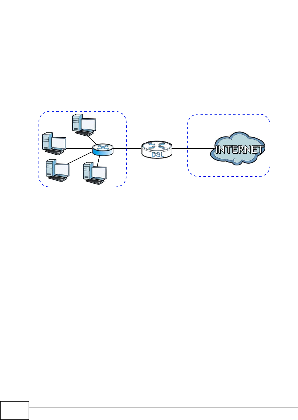
Chapter 7 Home Networking
VMG8324-B10A / VMG8324-B30A Series User’s Guide
128
7.12 Technical Reference
This sect ion provides som e t echnical background inform ation about the topics covered in t his
chapt er.
7.12.1 LANs, WANs and the Device
The act ual physical connection determ ines whet her the Device ports are LAN or WAN port s. There
are t wo separate I P networks, one inside t he LAN net work and t he ot her out side the WAN net work
as shown next .
Figure 65 LAN and WAN I P Addresses
7.12.2 DHCP Setup
DHCP ( Dynam ic Host Configuration Prot ocol, RFC 2131 and RFC 2132) allows individual clients t o
obt ain TCP/ I P configurat ion at st art- up fr om a server. You can configure t he Device as a DHCP
server or disable it . When configured as a server, the Device provides the TCP/ I P configurat ion for
the clients. I f you t ur n DHCP service off, you m ust have anot her DHCP server on your LAN, or else
the com put er m ust be m anually configured.
IP Pool Setup
The Device is pr e- configur ed w it h a pool of I P addresses for t he DHCP clients ( DHCP Pool) . See t he
product specificat ions in the appendices. Do not assign stat ic I P addresses from the DHCP pool t o
your LAN com put ers.
7.12.3 DNS Server Addresses
DNS (Dom ain Nam e System ) m aps a dom ain nam e to it s corresponding I P addr ess and vice versa.
The DNS server is ext rem ely im port ant because wit hout it , you m ust know t he I P address of a
com put er before you can access it . The DNS server addresses you ent er when you set up DHCP are
passed to t he client m achines along wit h the assigned I P address and subnet m ask.
There are two ways t hat an I SP dissem inat es the DNS ser ver addresses.
• The I SP tells you t he DNS server addresses, usually in t he form of an inform ation sheet, when
you sign up. I f your I SP gives you DNS server addresses, ent er them in t he D N S Se r ve r fields in
the DHCP Set u p screen.
WAN
LAN

Chapter 7 Home Networking
VMG8324-B10A / VMG8324-B30A Series User’s Guide 129
• Som e I SPs choose to dissem inat e the DNS server addresses using the DNS server extensions of
I PCP ( I P Cont r ol Protocol) after t he connect ion is up. I f your I SP did not give you explicit DNS
servers, chances are t he DNS servers are conveyed t hrough I PCP negot iat ion. The Device
supports t he I PCP DNS server ext ensions t hrough the DNS proxy feat ure.
Please not e that DNS proxy works only when t he I SP uses t he I PCP DNS server extensions. I t
does not m ean you can leave t he DNS servers out of the DHCP setup under all circum st ances. I f
your I SP gives you ex plicit DNS ser vers, m ake sure that you enter t heir I P addresses in the
DH CP Se t u p screen.
7.12.4 LAN TCP/IP
The Device has built- in DHCP server capability t hat assigns I P addresses and DNS servers t o
system s t hat support DHCP client capabilit y.
IP Address and Subnet Mask
Sim ilar t o t he way houses on a st reet share a com m on street nam e, so t oo do com put ers on a LAN
share one com m on net work num ber.
Wher e you obt ain your net work num ber depends on your part icular situat ion. I f t he I SP or your
net work adm inist rat or assigns you a block of regist ered I P addresses, follow t heir instructions in
select ing t he I P addresses and t he subnet m ask.
I f t he I SP did not explicit ly give you an I P net work num ber, t hen m ost likely you have a single user
account and the I SP will assign you a dynam ic I P address when t he connect ion is established. I f this
is t he case, it is recom m ended t hat you select a net work num ber from 192.168.0.0 t o
192.168.255.0 and you m ust enable t he Network Address Translat ion (NAT) feature of t he Device.
The I nt ernet Assigned Num ber Aut hority ( I ANA) reserved t his block of addr esses specifically for
privat e use; please do not use any ot her num ber unless you are t old otherwise. Let 's say you select
192.168.1.0 as t he net work num ber; which covers 254 individual addresses, from 192.168.1.1 t o
192.168.1.254 ( zero and 255 are reserved) . I n ot her words, t he first t hree num bers specify t he
net work num ber while the last num ber ident ifies an individual com put er on t hat net work.
Once you have decided on t he net work num ber, pick an I P address t hat is easy t o rem em ber, for
inst ance, 192.168.1.1, for your Device, but m ake sur e that no ot her device on your net work is
using t hat I P address.
The subnet m ask specifies the net work num ber port ion of an I P address. Your Device will com put e
the subnet m ask autom at ically based on t he I P address t hat you entered. You don't need to change
the subnet m ask com put ed by t he Device unless you are inst ructed t o do ot herwise.
Private IP Addresses
Every m achine on t he I nt ernet m ust have a unique address. I f your net works are isolat ed from the
I nt ernet , for exam ple, only bet ween your two branch offices, you can assign any I P addresses t o
the host s wit hout problem s. However, t he I nt er net Assigned Num bers Aut hority ( I ANA) has
reserved t he following t hr ee blocks of I P addresses specifically for privat e networks:
• 10.0.0.0 — 10.255.255.255
• 172.16.0.0 — 172.31.255.255
• 192.168.0.0 — 192.168.255.255

Chapter 7 Home Networking
VMG8324-B10A / VMG8324-B30A Series User’s Guide
130
You can obt ain your I P address from t he I ANA, from an I SP or it can be assigned from a privat e
net work. I f you belong t o a sm all organizat ion and your I nternet access is t hrough an I SP, t he I SP
can provide you wit h t he I nt ernet addresses for your local net works. On t he other hand, if you are
part of a m uch larger organizat ion, you should consult your net work adm inist rat or for t he
appropriate I P addresses.
Not e: Regardless of your part icular situat ion, do not create an arbit rary I P address;
always follow t he guidelines above. For m ore inform at ion on address assignm ent ,
please refer t o RFC 1597, “Address Allocat ion for Privat e I nternets” and RFC 1466,
“ Guidelines for Managem ent of I P Address Space”.
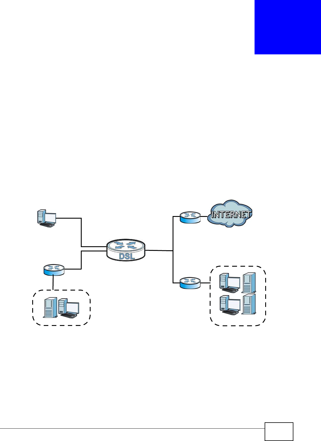
VMG8324-B10A / VMG8324-B30A Series User’s Guide 131
CHAPTER 8
Routing
8.1 Overview
The Device usually uses t he default gat eway t o rout e out bound t raffic from com puters on t he LAN
to the I nt ernet . To have the Device send dat a t o devices not reachable t hrough t he default gat eway,
use stat ic routes.
For exam ple, t he next figure shows a com puter ( A) connected t o the Device’s LAN int erface. The
Device rout es m ost t raffic from A to the I nt ernet t hrough t he Device’s default gateway ( R1 ) . You
create one st atic route t o connect t o services offered by your I SP behind rout er R2 . You creat e
another static route t o com m unicat e wit h a separate net work behind a rout er R3 connect ed t o the
LAN.
Figure 66 Exam ple of Rout ing Topology
WAN
R1
R2
A
R3
LAN
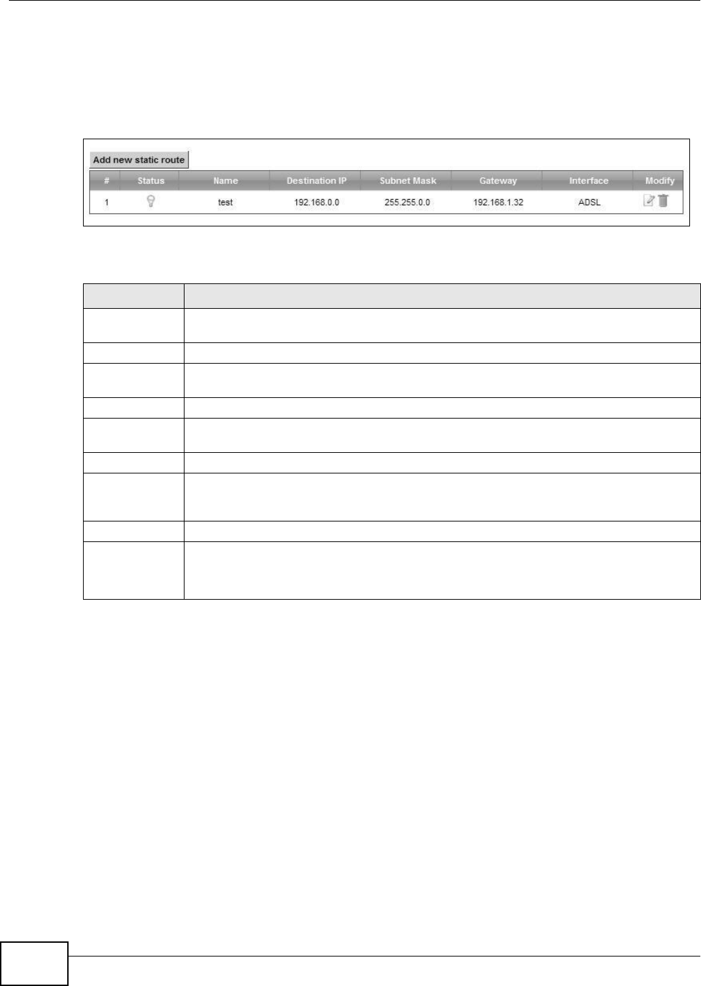
Chapter 8 Routing
VMG8324-B10A / VMG8324-B30A Series User’s Guide
132
8.2 The Routing Screen
Use t his scr een t o view and configure the st at ic route rules on the Device. Click N e t w or k Se t t ing
> Routing > St a t ic Route t o open t he following screen.
Figure 67 Net work Sett ing > Rout ing > Stat ic Rout e
The following t able describes t he labels in this screen.
Table 40 Net work Sett ing > Rout ing > Stat ic Rout e
LABEL DESCRIPTION
Add new stat ic
rout e
Click t his to configure a new st at ic route.
#This is t he index num ber of the ent ry.
St atus This field display s whether t he static rout e is active or not . A yellow bulb signifies t hat t his
rout e is active. A gray bulb signifies t hat this rout e is not act ive.
Nam e This is the nam e t hat describes or ident ifies t his route.
Dest ination I P This param et er specifies t he I P network address of t he final destinat ion. Routing is always
based on net work num ber.
Subnet Mask This param et er specifies t he I P net work subnet m ask of t he final destinat ion.
Gateway This is the I P addr ess of t he gat eway. The gat eway is a rout er or swit ch on t he sam e
networ k segm ent as the device's LAN or WAN port. The gateway helps forward packet s to
their dest inat ions.
I nterface This is t he WAN inter face used for t his st atic rout e.
Modify Click t he Ed it icon to edit the st at ic rout e on the Device.
Click the De let e icon t o rem ove a st at ic route fr om the Device. A window displays asking
you to confirm t hat you w ant t o delet e t he rout e.
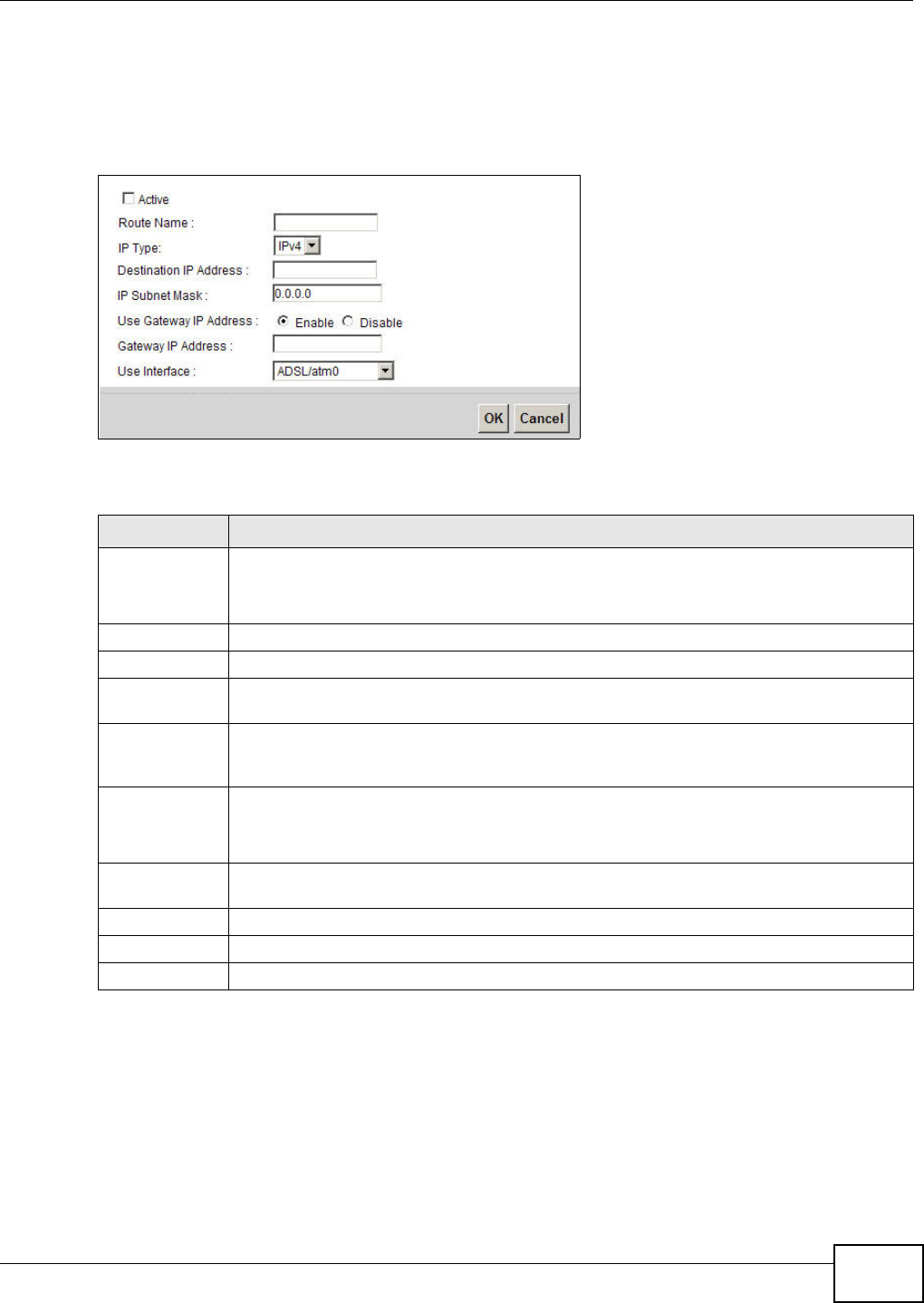
Chapter 8 Routing
VMG8324-B10A / VMG8324-B30A Series User’s Guide 133
8.2.1 Add/Edit Static Route
Use t his screen t o add or edit a st at ic route. Click Add ne w st a t ic r out e in t he Rou t in g screen or
the Ed it icon next to the st at ic rout e you want to edit . The screen shown next appears.
Figure 68 Rout ing: Add/ Edit
The following t able describes t he labels in this screen.
Table 41 Rout ing: Add/ Edit
LABEL DESCRIPTION
Act ive This field allows you t o act ivate/ deact ivat e t his stat ic route.
Select this t o enable t he st at ic route. Clear t his t o disable this st atic route without having t o
delet e the ent ry.
Rout e Nam e Enter a descript ive nam e for t he st at ic route.
I P Type Select whet her your I P type is I Pv4 or I Pv6 .
Dest ination I P
Address
Enter t he I Pv4 or I Pv6 net work address of t he final destinat ion.
I P Subnet Mask I f you are using I Pv4 and need t o specify a rout e t o a single host, use a subnet m ask of
255.255.255.255 in t he subnet m ask field t o force t he net work num ber to be identical to
the host I D. Ent er the I P subnet m ask her e.
Use Gat eway I P
Address
The gateway is a router or swit ch on the sam e net work segm ent as t he device's LAN or WAN
port . The gat eway helps forward packets t o t heir destinat ions.
I f you want t o use t he gat eway I P address, select Ena ble.
Gateway I P
Address
Ent er t he I P address of the gateway.
Use I nt er face Select t he WAN int erface you want t o use for this st at ic route.
Apply Click Apply t o save your changes.
Cancel Click Ca ncel t o exit this screen w ithout saving.
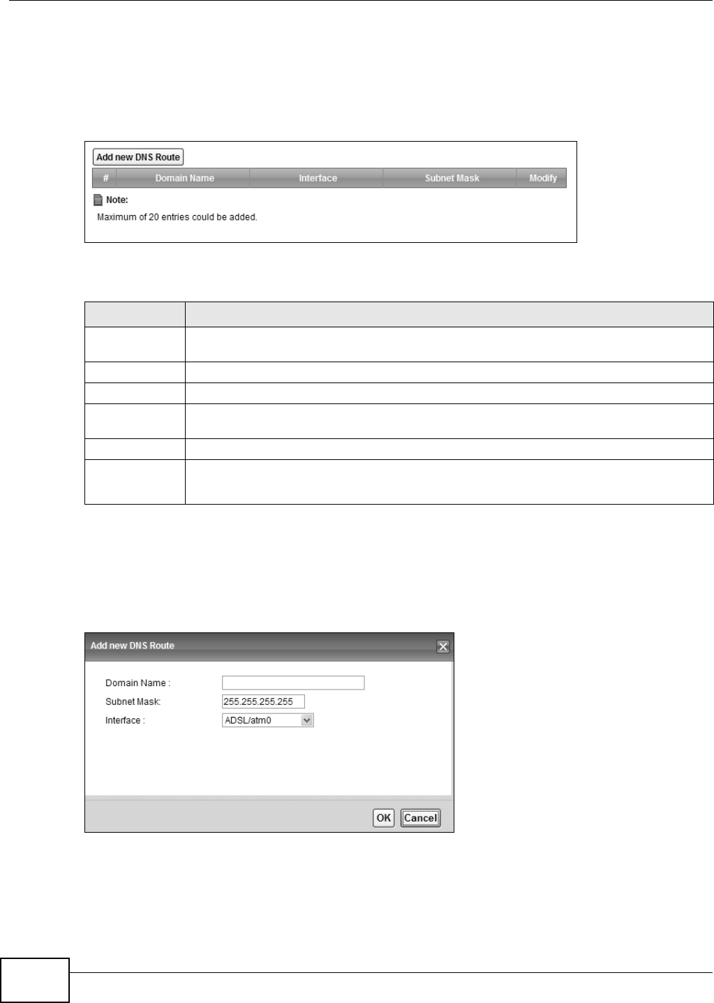
Chapter 8 Routing
VMG8324-B10A / VMG8324-B30A Series User’s Guide
134
8.3 The DNS Route Screen
Use t his screen t o view and configure DNS r outes on t he Device. Click Ne t w or k Set t in g >
Rout ing > D N S Rout e t o open t he following screen.
Figure 69 Net work Set t ing > Rout ing > DNS Rout e
The following t able describes t he labels in this screen.
8.3.1 The DNS Route Add Screen
You can m anually add t he Device’s DNS rout e ent ry. Click Add new DN S Rout e in the N e t w ork
Set t ing > Rout ing > DN S Route screen. The screen shown next appears.
Figure 70 DNS Route Add
Table 42 Net work Sett ing > Rout ing > DNS Rout e
LABEL DESCRIPTION
Add new DNS
Rout e
Click t his t o add a new DNS rout e.
#This is t he index num ber of a DNS route.
Dom ain Nam e This is the host nam e or dom ain nam e of the DNS route entry.
I nterface This is the WAN connect ion through w hich t he Device forwards DNS request s for this dom ain
nam e.
Subnet Mask This is t he subnet m ask of t he DNS rout e ent ry.
Modify Click the Ed it icon to m odify the DNS route.
Click t he D e le t e icon t o delete t he DNS rout e.
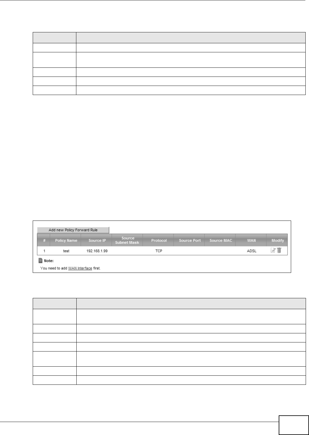
Chapter 8 Routing
VMG8324-B10A / VMG8324-B30A Series User’s Guide 135
The following t able describes t he labels in this screen.
8.4 The Policy Forwarding Screen
Tradit ionally, routing is based on t he dest inat ion addr ess only and t he Device t akes the shortest
pat h to forward a packet. Policy forwarding allows t he Device t o override t he default rout ing
behavior and alter t he packet forwarding based on the policy defined by the net w ork adm inist rator.
Policy-based rout ing is applied t o out going packets, prior t o the norm al routing.
You can use source- based policy forwarding to direct t raffic from different users t hrough different
connect ions or distribute t raffic am ong m ultiple paths for load sharing.
The Policy For w arding screen let you view and configure rout ing policies on t he Device. Click
N e t w ork Se t t ing > Rout in g > Policy For w a rding to open the follow ing screen.
Figure 71 Net work Sett ing > Rout ing > Policy Forwarding
The following t able describes t he labels in this screen.
Table 43 DNS Rout e Add
LABEL DESCRIPTION
Dom ain Nam e Ent er the dom ain nam e of t he DNS route entry.
I nterface Select the WAN connect ion through which the Device forwards DNS request s for t his dom ain
nam e.
Subnet Mask Ent er t he subnet m ask of t he DNS route ent ry.
OK Click this to save your changes.
Cancel Click t his to exit t his screen wit hout saving any changes.
Table 44 Net work Set t ing > Rout ing > Policy Forwarding
LABEL DESCRIPTION
Add new Policy
Forward Rule
Click t his t o creat e a new policy forwarding rule.
#This is t he index num ber of t he entry.
Policy Nam e This is the nam e of t he rule.
Source I P This is the source I P address.
Source Subnet
Mask
his is the source subnet m ask address.
Prot ocol This is the transport layer protocol.
Source Port This is t he source port num ber.
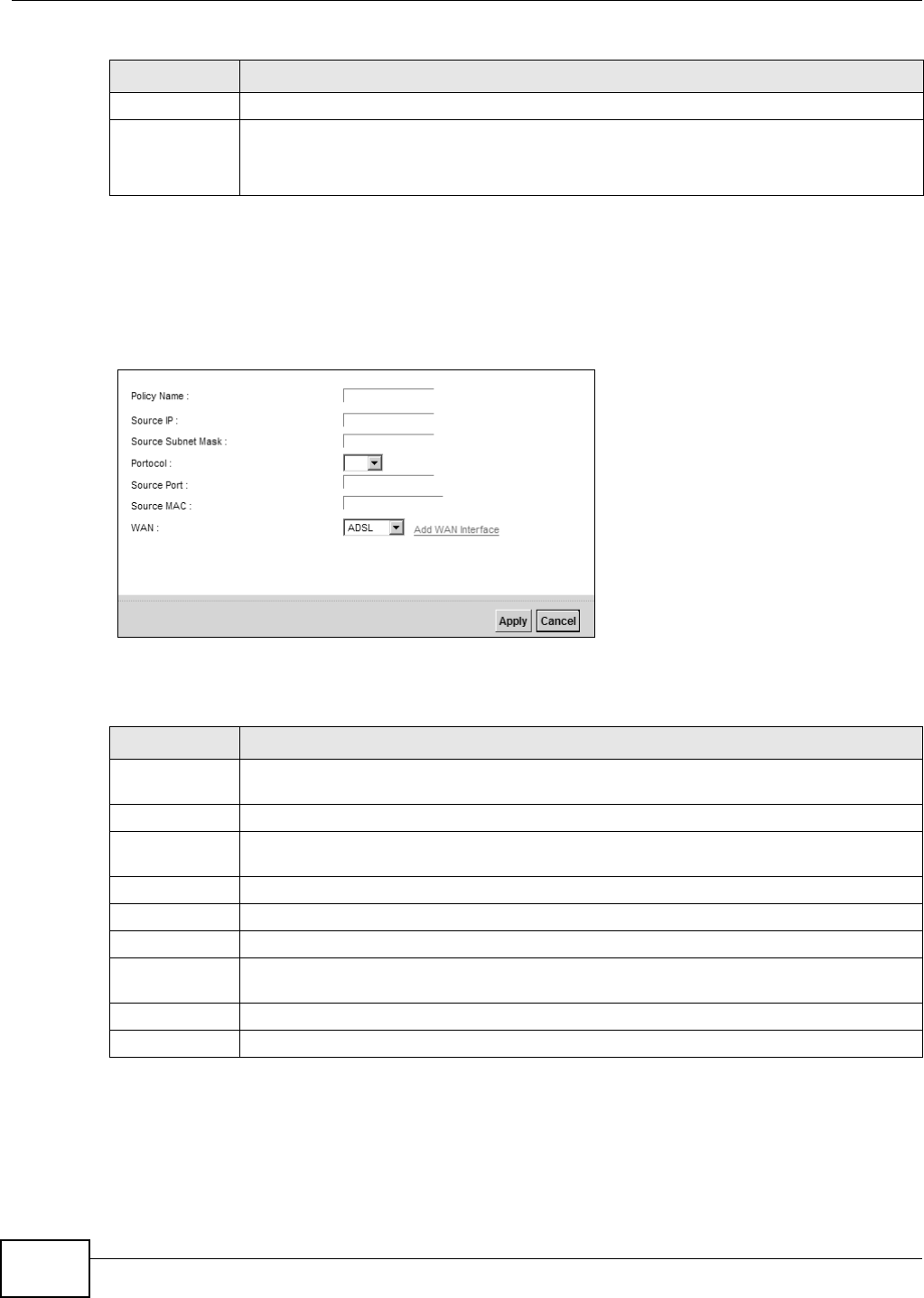
Chapter 8 Routing
VMG8324-B10A / VMG8324-B30A Series User’s Guide
136
8.4.1 Add/Edit Policy Forwarding
Click Add ne w Policy For w ar d Ru le in the Policy For w arding screen or click t he Edit icon next
to a policy. Use t his screen to configure t he required inform at ion for a policy rout e.
Figure 72 Policy For warding: Add/ Edit
The following t able describes t he labels in this screen.
WAN This is the WAN int erface t hrough which the traffic is routed.
Modify Click the Ed it icon t o edit t his policy.
Click t he D e le t e icon t o rem ove a policy from t he Dev ice. A window displays asking you t o
confir m t hat you want t o delete t he policy.
Table 44 Net work Set t ing > Rout ing > Policy Forwarding ( continued)
LABEL DESCRIPTION
Table 45 Policy Forwarding: Add/ Edit
LABEL DESCRIPTION
Policy Nam e Ent er a descriptive nam e of up to 8 print able English keyboard charact ers, not including
spaces.
Source I P Ent er t he source I P address.
Source Subnet
Mask
Enter the source subnet m ask address.
Prot ocol Select the transport layer prot ocol ( TCP or UD P) .
Source Port Ent er t he source port num ber.
Source MAC Ent er t he source MAC address.
WAN Select a WAN int erface t hrough which t he t raffic is sent . You m ust have t he WAN
int erface( s) already configured in t he Broa dband screens.
Apply Click Apply t o save your changes.
Cancel Click Ca ncel t o exit this screen w ithout saving.
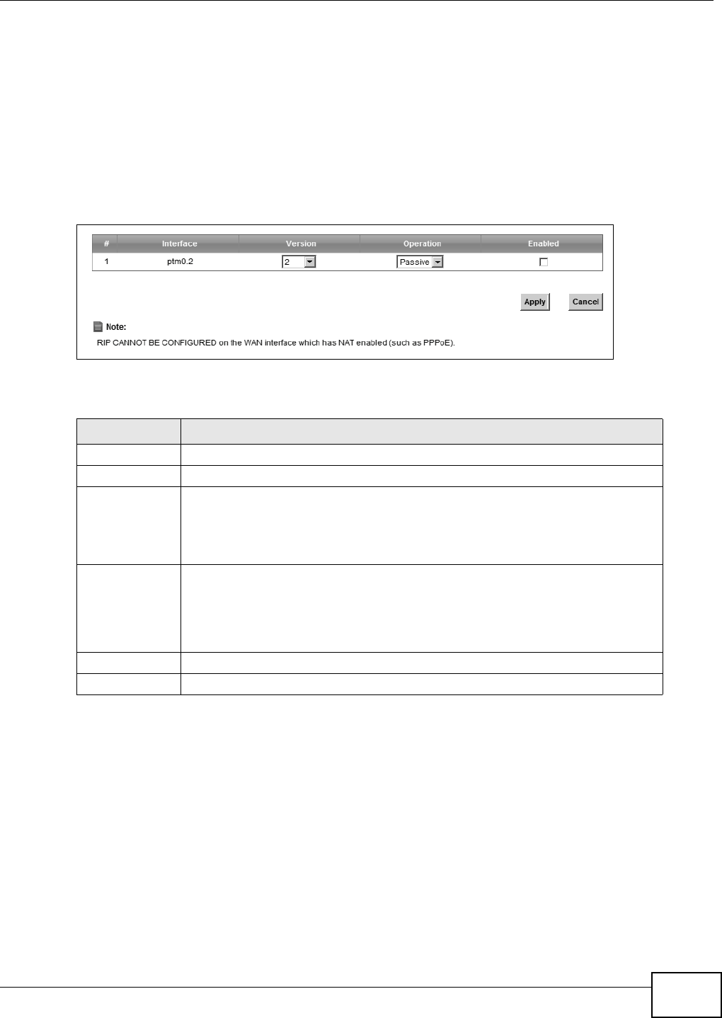
Chapter 8 Routing
VMG8324-B10A / VMG8324-B30A Series User’s Guide 137
8.5 RIP
Rout ing I nform ation Protocol ( RI P, RFC 1058 and RFC 1389) allows a device to exchange rout ing
inform at ion wit h other routers.
8.5.1 The RIP Screen
Click N et w or k Se t t ing > Rout ing > RI P to open t he RI P screen.
Figure 73 RI P
The following t able describes t he labels in this screen.
Table 46 RI P
LABEL DESCRIPTION
#This is t he index of t he interface in which t he RI P set ting is used.
I nterface This is t he nam e of t he int erface in which t he RI P setting is used.
Ve r sio n The RIP version contr ols t he form at and the br oadcasting m et hod of t he RIP
packet s that t he Device sends ( it recognizes bot h form ats when receiving) . RI P
version 1 is univer sally support ed but RI P version 2 carries m ore inform at ion. RIP
version 1 is pr obably adequate for m ost net works, unless you have an unusual
net work topology.
Operation Select Passive t o have t he Device update the rout ing t able based on the RIP
packets received from neighbors but not advert ise it s rout e inform at ion to ot her
rout ers in this interface.
Select Act iv e to have the Dev ice adver t ise it s route inform ation and also listen for
rout ing updat es from neighboring rout er s.
Enabled Select the check box to act ivat e t he set t ings.
Apply Click Apply t o save your changes back t o t he Dev ice.

Chapter 8 Routing
VMG8324-B10A / VMG8324-B30A Series User’s Guide
138

VMG8324-B10A / VMG8324-B30A Series User’s Guide 139
CHAPTER 9
Quality of Service (QoS)
9.1 Overview
Quality of Service (QoS) refer s t o bot h a net work’s ability to deliver dat a wit h m inim um delay, and
the net working m et hods used t o control t he use of bandwidt h. Wit hout QoS, all traffic dat a is
equally likely t o be dropped when t he network is congest ed. This can cause a reduct ion in net w ork
perform ance and m ake t he network inadequat e for t im e- critical applicat ion such as video- on-
dem and.
Configure QoS on t he Device to group and prioritize applicat ion t raffic and fine-t une net work
perform ance. Set t ing up QoS involves t hese st eps:
1Configure classifiers t o sort traffic int o different flows.
2Assign priority and define act ions t o be perform ed for a classified traffic flow.
The Device assigns each packet a priority and t hen queues t he packet accordingly. Packet s assigned
a high priority are processed m ore quickly t han t hose with low priorit y if t here is congest ion,
allowing t im e- sensit ive applicat ions t o flow m ore sm oot hly. Tim e- sensit ive applicat ions include both
those that require a low level of lat ency ( delay) and a low level of j it t er ( variat ions in delay) such as
Voice over I P ( VoI P) or I nt ernet gam ing, and those for which j itt er alone is a problem such as
I nt ernet radio or st ream ing video.
This chapt er contains inform at ion about configuring QoS and editing classifiers.
9.1.1 What You Can Do in this Chapter
• The Genera l screen lets you enable or disable QoS and set t he upst ream bandwidt h ( Sect ion 9.3
on page 141) .
• The Qu e u e Se t up screen let s you configure QoS queue assignm ent (Sect ion 9.4 on page 142) .
• The Cla ss Se t u p scr een lets you add, edit or delet e QoS classifiers (Sect ion 9.5 on page 144) .
• The Policer Se t u p screen lets you add, edit or delet e QoS policers (Section 9.5 on page 144) .
9.2 What You Need to Know
The following t erm s and concept s m ay help as you read through t his chapt er.
QoS versus Cos
QoS is used to prioritize source-t o- dest ination t raffic flows. All packet s in t he sam e flow are given
the sam e priorit y. CoS ( class of service) is a way of m anaging traffic in a network by grouping
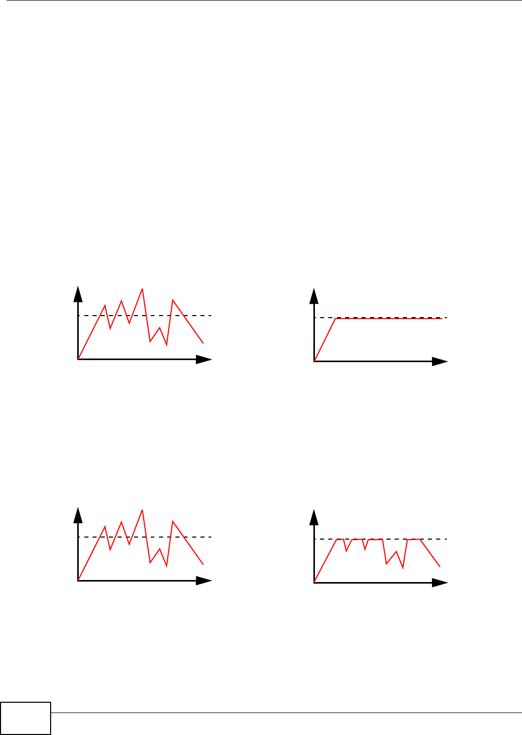
Chapter 9 Quality of Service (QoS)
VMG8324-B10A / VMG8324-B30A Series User’s Guide
140
sim ilar t ypes of t raffic together and t r eating each type as a class. You can use CoS t o give different
priorities t o different packet t ypes.
CoS t echnologies include I EEE 802.1p layer 2 t agging and DiffServ ( Differ entiat ed Services or DS) .
I EEE 802.1p t agging m akes use of t hree bit s in the packet header, while DiffServ is a new protocol
and defines a new DS field, which replaces t he eight- bit ToS ( Type of Service) field in t he I P header.
Tagging and Marking
I n a QoS class, you can configure whet her t o add or change t he DSCP ( DiffServ Code Point) value,
I EEE 802.1p priorit y level and VLAN I D num ber in a m atched packet. When t he packet passes
through a com pat ible net work, t he net working device, such as a backbone swit ch, can provide
specific t reat m ent or service based on t he t ag or m arker.
Traffic Shaping
Bursty t raffic m ay cause net work congest ion. Traffic shaping regulates packets t o be t ransm itt ed
wit h a pr e- conf igur ed dat a t ransm ission rat e using bu ffer s ( or queu es) . Your Dev ice u ses t he Token
Bucket algorit hm to allow a cer t ain am ount of large bur st s while keeping a lim it at the average rat e.
Traffic Policing
Traffic policing is t he lim it ing of the input or out put t ransm ission rate of a class of traffic on t he
basis of user- defined crit eria. Traffic policing m ethods m easure t raffic flows against user- defined
criteria and ident ify it as eit her conform ing, exceeding or violat ing t he crit er ia.
The Device support s t hree incom ing t raffic m et ering algorithm s: Token Bucket Filt er ( TBF), Single
Rate Two Color Maker ( srTCM) , and Two Rat e Two Color Marker ( t rTCM) . You can specify act ions
Traffic
Tim e
Traffic Rate
Tr a f f i c
Tim e
Traffic Rate
( Before Traffic Shaping) ( After Traffic Shaping)
Traffic
Tim e
Traffic Rate
Tr a f f i c
Tim e
Traffic Rate
( Before Traffic Policing) ( After Traffic Policing)
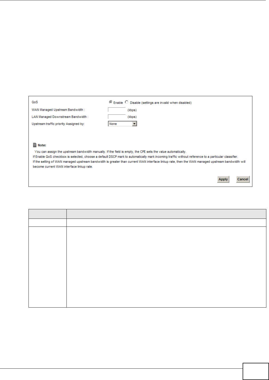
Chapter 9 Quality of Service (QoS)
VMG8324-B10A / VMG8324-B30A Series User’s Guide 141
which are perform ed on t he colored packets. See Sect ion 9.8 on page 152 for m ore inform ation on
each m etering algorit hm .
9.3 The Quality of Service General Screen
Click N et w ork Set t in g > QoS > Ge n e ra l t o open the screen as shown next .
Use t his scr een t o enable or disable QoS and set the upstream bandwidth. See Sect ion 9.1 on page
139 for m ore inform at ion.
Figure 74 Net work Set t ings > QoS > General
The following t able describes t he labels in this screen.
Table 47 Net work Set ting > QoS > General
LABEL DESCRIPTION
QoS Select t he En a ble check box t o t ur n on QoS to im prove your net w ork perfor m ance.
WAN Managed
Upst ream
Bandwidt h
Enter t he am ount of upst ream bandw idt h for t he WAN int erfaces t hat you want t o allocate
using QoS.
The recom m endat ion is t o set this speed t o m atch t he int erfaces’ act ual t ransm ission speed.
For exam ple, set the WAN int erfaces’ speed to 100000 kbps if your I nt ernet connect ion has
an upst ream t ransm ission speed of 100 Mbps.
You can set t his num ber higher t han t he interfaces’ act ual t ransm ission speed. The Device
uses up t o 95% of the DSL por t ’s actual upst ream t ransm ission speed even if y ou set t his
num ber higher t han t he DSL por t ’s actual t ransm ission speed.
You can also set t his num ber lower t han t he interfaces’ act ual transm ission speed. This will
cause the Device to not use som e of t he int erfaces’ available bandwidt h.
I f you leave t his field blank, the Device aut om at ically set s this num ber to be 95% of t he
WAN int erfaces’ act ual upst ream t ransm ission speed.
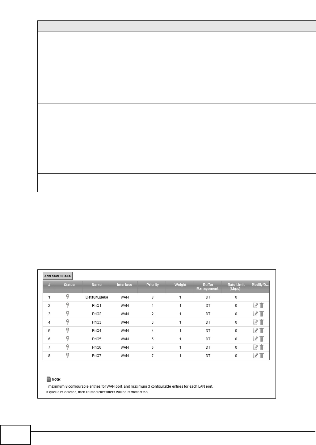
Chapter 9 Quality of Service (QoS)
VMG8324-B10A / VMG8324-B30A Series User’s Guide
142
9.4 The Queue Setup Screen
Click N et w ork Se t t ing > QoS > Queue Set u p to open t he screen as shown next .
Use t his scr een t o configure QoS queue assignm ent .
Figure 75 Net work Set t ing > QoS > Queue Set up
LAN Managed
Dow nst ream
Bandwidt h
Enter t he am ount of downst ream bandwidt h for t he LAN interfaces ( including WLAN) t hat
you want t o allocat e using QoS.
The recom m endat ion is to set this speed to m atch the WAN int erfaces’ actual t ransm ission
speed. For exam ple, set the LAN m anaged downstream bandwidt h to 100000 kbps if you
use a 100 Mbps wired Ethernet WAN connect ion.
You can also set t his num ber lower than t he WAN interfaces’ act ual t ransm ission speed. This
will cause t he Device t o not use som e of t he interfaces’ available bandw idt h.
I f you leave this field blank, the Device autom at ically set s t his t o t he LAN int erfaces’
m axim um supported connection speed.
Upst ream
traffic priority
Assigned by
Select how t he Device assigns priorit ies t o various upst ream t raffic flow s.
•N one : Disables aut o priority m apping and has t he Device put packet s int o t he queues
accor ding to your classificat ion rules. Traffic which does not m at ch any of t he
classification rules is m apped into t he default queue with t he lowest priority.
•Et h ern e t Pr ior it y: Aut om at ically assign priorit y based on t he I EEE 802.1p priorit y level.
•I P Pre ce de n ce : Aut om at ically assign priorit y based on the first three bit s of the TOS
field in t he I P header.
•Pa ck e t Len gt h : Aut om at ically assign pr iority based on t he packet size. Sm aller packets
get higher pr iorit y since control, signaling, VoI P, internet gam ing, or ot her real-tim e
packets are usually sm all while larger packets are usually best effort data packet s like
file t ransfers.
Apply Click Apply t o save your changes.
Cancel Click Ca nce l t o rest ore your previously saved set t ings.
Table 47 Net work Set ting > QoS > General ( cont inued) (continued)
LABEL DESCRIPTION
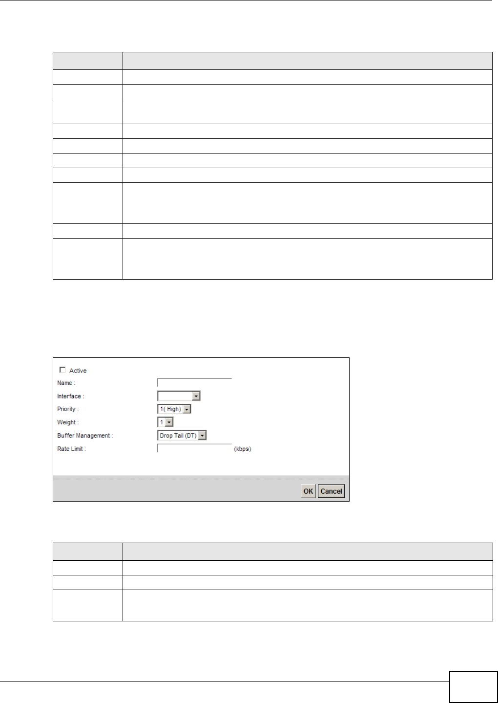
Chapter 9 Quality of Service (QoS)
VMG8324-B10A / VMG8324-B30A Series User’s Guide 143
The following t able describes t he labels in this screen.
9.4.1 Adding a QoS Queue
Click Add ne w Queue or t he edit icon in the Qu e ue Se t up screen to configure a queue.
Figure 76 Queue Set up: Add
The following t able describes t he labels in this screen.
Table 48 Net work Set t ing > QoS > Queue Set up
LABEL DESCRIPTION
Add new Queue Click this button to creat e a new queue ent ry.
#This is t he index num ber of the ent ry.
St atus This field displays whether t he queue is act ive or not . A yellow bulb signifies that this queue
is act ive. A gray bulb signifies that t his queue is not act ive.
Nam e This shows t he descr ipt ive nam e of t his queue.
I nterface This shows the nam e of t he Dev ice’s int erface t hrough which t raffic in t his queue passes.
Priority This show s t he priorit y of this queue.
Weig h t This shows t he weight of t his queue.
Buffer
Managem ent
This shows the queue m anagem ent algorit hm used for t his queue.
Queue m anagem ent algorit hm s det erm ine how t he Dev ice should handle packet s when it
receives too m any ( net work congestion) .
Rat e Lim it This shows the m axim um t ransm ission rate allowed for t raffic on t his queue.
Modify Click t he Ed it icon t o edit t he queue.
Click the De let e icon t o delete an ex ist ing queue. Not e t hat subsequent rules m ove up by
one when you take this act ion.
Table 49 Queue Setup: Add
LABEL DESCRIPTION
Act ive Select t o enable or disable t his queue.
Nam e Ent er the descript ive nam e of t his queue.
I nterface Select t he int erface to which this queue is applied.
This field is read- only if you ar e edit ing t he queue.
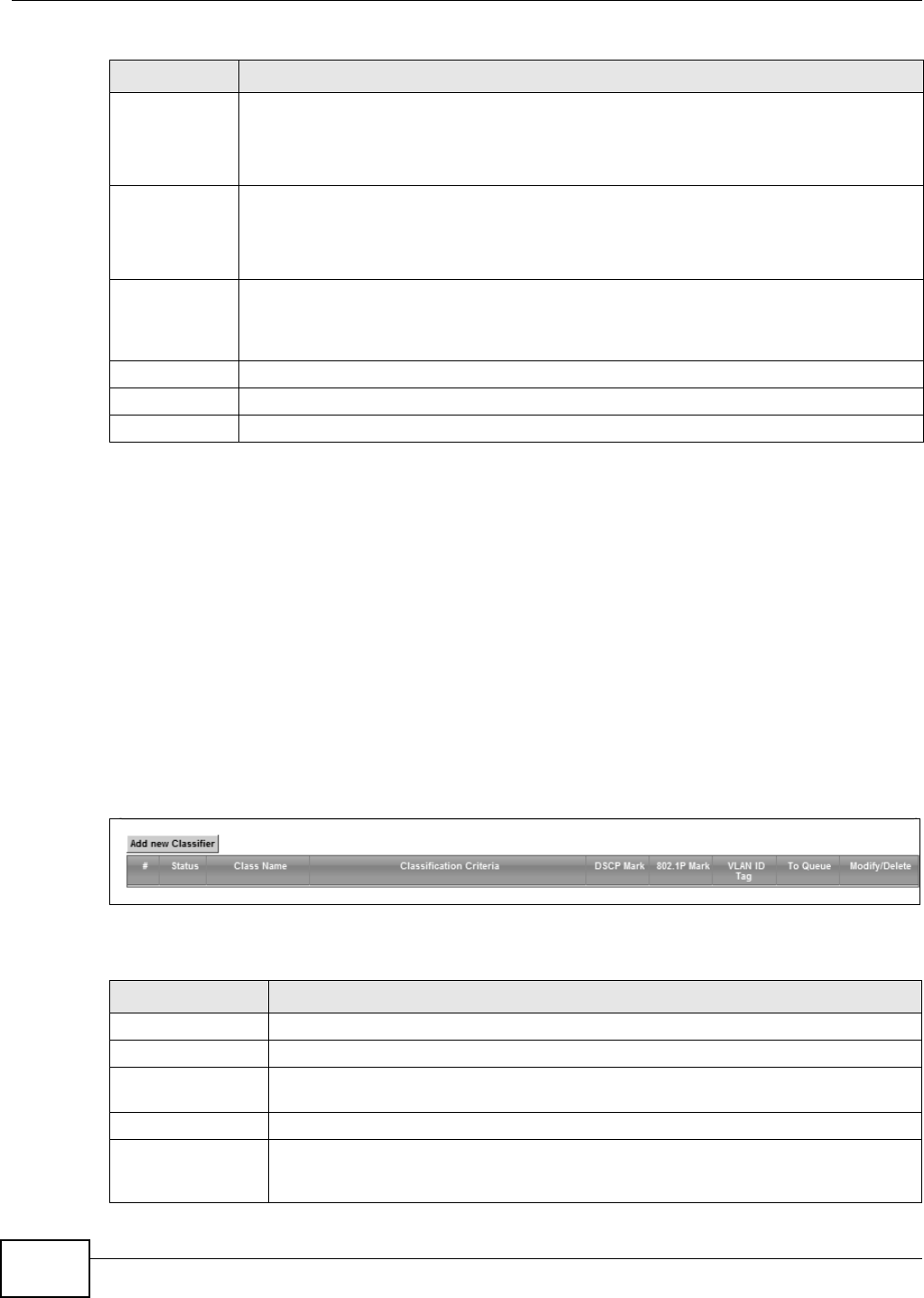
Chapter 9 Quality of Service (QoS)
VMG8324-B10A / VMG8324-B30A Series User’s Guide
144
9.5 The Class Setup Screen
Use t his screen to add, edit or delet e QoS classifiers. A classifier groups t raffic into dat a flows
according t o specific crit eria such as t he source address, destinat ion address, source port num ber,
dest inat ion port num ber or incom ing interface. For exam ple, you can configure a classifier to select
traffic from the sam e prot ocol port ( such as Telnet ) to form a flow.
You can give different priorit ies to traffic t hat t he Device forwar ds out t hrough t he WAN int er face.
Give high priority t o voice and video to m ake t hem run m ore sm oot hly. Sim ilarly, give low priorit y
to m any large file downloads so t hat they do not reduce the qualit y of ot her applicat ions.
Click N et w ork Se t t ing > QoS > Cla ss Se t up to open the following screen.
Figure 77 Net work Set t ing > QoS > Class Setup
The following t able describes t he labels in this screen.
Priority Select the priority level ( from 1 t o 7) of this queue.
The sm aller t he num ber, t he higher the priorit y level. Traffic assigned t o higher priorit y
queues gets through fast er while t raffic in lower priority queues is dropped if the networ k is
congest ed.
Weig h t Select t he weight ( from 1 to 8) of t his queue.
I f t wo queues have t he sam e priorit y level, t he Device div ides t he bandwidth across the
queues according t o t heir w eights. Queues wit h larger weights get m ore bandwidt h t han
queues wit h sm aller w eights.
Buffer
Managem ent
This field displays Drop Ta il ( DT) . Dr op Ta il ( D T) is a sim ple queue m anagem ent
algorit hm t hat allows t he Dev ice buffer t o accept as m any packets as it can unt il it is full.
Once t he buffer is full, new packets t hat arrive are dropped until t here is space in the buffer
again ( packet s are t ransm it t ed out of it ) .
Rat e Lim it Specify t he m axim um t ransm ission rat e ( in Kbps) allow ed for t raffic on this queue.
OK Click OK t o save your changes.
Cancel Click Ca nce l to exit t his screen without saving.
Table 49 Queue Setup: Add ( cont inued)
LABEL DESCRIPTION
Table 50 Net work Sett ing > QoS > Class Set up
LABEL DESCRIPTION
Add new Classifier Click this t o create a new classifier.
#This is t he index num ber of t he entry.
St atus This field display s whet her t h e classif ier is act ive or not . A y ellow bulb sign ifies t h at t his
classifier is act iv e. A gray bulb signifies that t his classifier is not act iv e.
Class Nam e This is t he nam e of t he classifier.
Classification
Criteria
This show s crit er ia specified in t his classifier, for exam ple t he int erface from which
traffic of t his class should com e and t he source MAC address of t raffic that m at ches this
classifier.

Chapter 9 Quality of Service (QoS)
VMG8324-B10A / VMG8324-B30A Series User’s Guide 145
DSCP Mark This is t he DSCP num ber added t o t raffic of t his classifier.
802.1P Mark This is the I EEE 802.1p priorit y level assigned t o t raffic of this classifier.
VLAN I D Tag This is t he VLAN I D num ber assigned to traffic of t his classifier.
To Q u e u e This is t he nam e of t he queue in which t raffic of this classifier is put .
Modify Click t he Ed it icon t o edit the classifier.
Click the D ele t e icon t o delete an exist ing classifier. Note t hat subsequent rules m ove
up by one w hen you t ake this act ion.
Table 50 Net work Set t ing > QoS > Class Set up ( cont inued)
LABEL DESCRIPTION
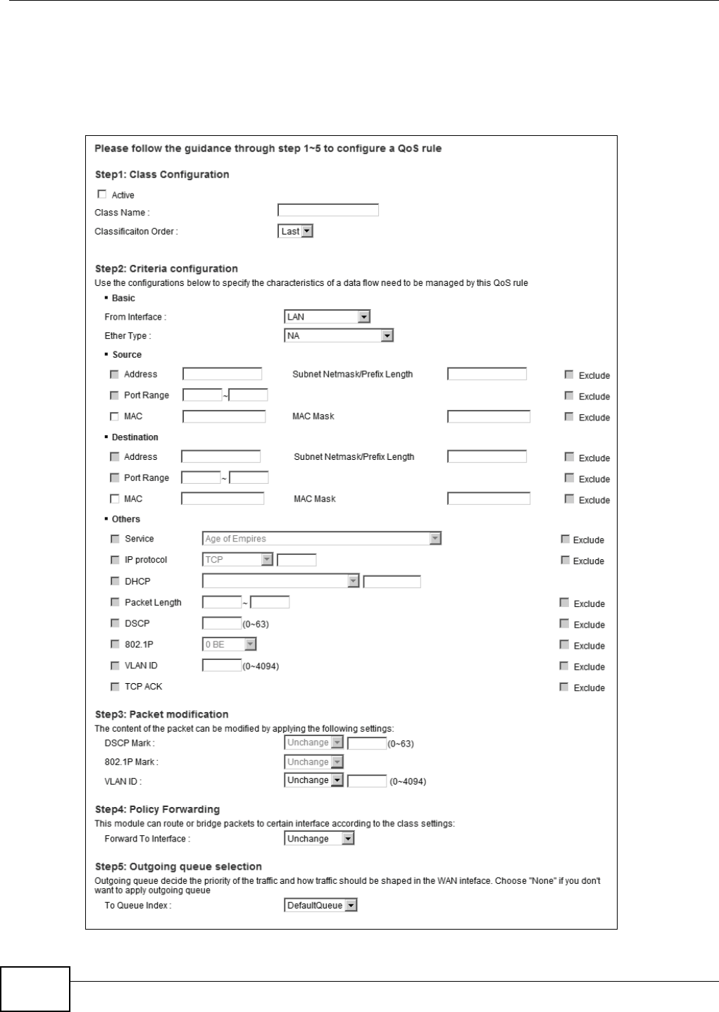
Chapter 9 Quality of Service (QoS)
VMG8324-B10A / VMG8324-B30A Series User’s Guide
146
9.5.1 Add/Edit QoS Class
Click Add ne w Classifie r in the Cla ss Se t u p screen or t he Edit icon next t o a classifier t o open
the following screen.
Figure 78 Class Set up: Add/ Edit

Chapter 9 Quality of Service (QoS)
VMG8324-B10A / VMG8324-B30A Series User’s Guide 147
The following t able describes t he labels in this screen.
Table 51 Class Set up: Add/ Edit
LABEL DESCRIPTION
Act ive Select t his to enable t his classifier.
Class Nam e Ent er a descriptive nam e of up to 15 print able English keyboard charact ers, not including
spaces.
Classification
Order
Select an exist ing num ber for where you want t o put this classifier t o m ove t he classifier t o
the num ber you select ed after clicking Apply.
Select La st t o put t his rule in the back of t he classifier list .
From I nt erface I f you want t o classify t he t raffic by an ingress int erface, select an interface from t he From
I n t e rfa ce drop- down list box.
Ether Type Select a predefined applicat ion t o configure a class for t he m at ched traffic.
I f you select I P, you also need t o configure source or dest ination MAC address, I P address,
DHCP options, DSCP value or t he prot ocol t ype.
I f you select 8 0 2 .1 Q, you can configure an 802.1p pr ior it y level.
Source
Address Select the check box and ent er the source I P address in dot t ed decim al notat ion. A blank
source I P address m eans any source I P address.
Subnet
Netm ask
Enter t he source subnet m ask.
Por t Range If you select TCP or UD P in t he I P Prot ocol field, select the check box and ent er t he port
num ber( s) of t he source.
MAC Select the check box and ent er t he source MAC address of t he packet.
MAC Mask Type the m ask for t he specified MAC address t o det er m ine which bit s a packet ’s MAC
addr ess should m at ch.
Ent er “ f ” for each bit of t he specified source MAC address t hat t he t raffic’s MAC addr ess
should m at ch. Ent er “ 0” for the bit ( s) of the m at ched t raffic’s MAC address, which can be of
any hexadecim al charact er(s) . For exam ple, if you set t he MAC address to
00: 13: 49: 00: 00: 00 and the m ask to ff: ff: ff: 00: 00: 00, a packet wit h a MAC address of
00: 13: 49: 12: 34: 56 m at ches t his criteria.
Exclude Select this opt ion to exclude the packets t hat m at ch t he specified criteria from t his classifier.
Dest ination
Address Select the check box and ent er the source I P address in dot t ed decim al notat ion. A blank
source I P address m eans any source I P address.
Subnet
Netm ask
Enter t he source subnet m ask.
Por t Range If you select TCP or UD P in t he I P Prot ocol field, select the check box and ent er t he port
num ber( s) of t he source.
MAC Select the check box and ent er t he source MAC address of t he packet.
MAC Mask Type the m ask for t he specified MAC address t o det er m ine which bit s a packet ’s MAC
addr ess should m at ch.
Ent er “ f ” for each bit of t he specified source MAC address t hat t he t raffic’s MAC addr ess
should m at ch. Ent er “ 0” for the bit ( s) of the m at ched t raffic’s MAC address, which can be of
any hexadecim al charact er(s) . For exam ple, if you set t he MAC address to
00: 13: 49: 00: 00: 00 and the m ask to ff: ff: ff: 00: 00: 00, a packet wit h a MAC address of
00: 13: 49: 12: 34: 56 m at ches t his criteria.
Exclude Select this opt ion to exclude the packets t hat m at ch t he specified criteria from t his classifier.
Ot hers

Chapter 9 Quality of Service (QoS)
VMG8324-B10A / VMG8324-B30A Series User’s Guide
148
Service This field is available only when you select I P in the Et h er Type field.
This field sim plifies classifier configurat ion by allowing you to select a predefined
applicat ion. When you select a predefined applicat ion, you do not configure the rest of t he
filt er fields.
I P Prot ocol This field is available only when you select I P in t he Et he r Ty pe field.
Select this opt ion and select the pr ot ocol (service type) from TCP, UDP, I CM P or I GM P. I f
you select Use r def ine d, ent er t he protocol ( service t ype) num ber.
DHCP This field is available only when you select I P in t he Et h er Type field.
Select t his option and select a DHCP option.
I f you select Ve ndor Cla ss I D ( D H CP Opt ion 6 0 ) , ent er the Vendor Class I dentifier
( Opt ion 60) of t he m atched t raffic, such as t he t ype of t he hardware or firm ware.
I f you select Use r Cla ss I D ( DH CP Opt ion 7 7 ) , ent er a string t hat identifies t he user ’s
cat egory or applicat ion ty pe in the m at ched DHCP packet s.
Pack et
Length
This field is available only when you select I P in the Et her Type field.
Select this opt ion and ent er the m inim um and m axim um packet lengt h ( from 46 t o 1500) in
the fields provided.
DSCP This field is available only when you select I P in the Et her Type field.
Select t his option and specify a DSCP (DiffServ Code Point ) num ber bet ween 0 and 63 in t he
field provided.
802.1P This field is available only when you select 8 0 2 .1 Q in the Et h er Type field.
Select t his option and select a priorit y level (bet w een 0 and 7) from the dr op- down list box.
"0" is t he lowest priorit y level and "7" is t he highest .
VLAN I D This field is available only w hen you select 8 0 2 .1 Q in the Et h er Type field.
Select t his opt ion and specify a VLAN I D num ber.
TCP ACK This field is available only when you select I P in t he Et he r Ty pe field.
I f you select t his option, t he m at ched TCP packet s m ust cont ain t he ACK (Ack nowledge)
flag.
Exclude Select this opt ion to exclude the packets t hat m at ch t he specified criteria from t his classifier.
DSCP Mark This field is available only when you select I P in the Et her Type field.
I f you select M ark , ent er a DSCP value w it h which t he Device replaces t he DSCP field in t he
pack et s.
I f you select Uncha nge, the Device keep t he DSCP field in t he packet s.
802.1P Mark Select a pr ior it y level with which the Device replaces t he I EEE 802.1p prior it y field in t he
pack et s.
I f you select Uncha nge, the Device keep t he 802.1p pr iorit y field in the packet s.
VLAN I D I f you select Re m a rk, ent er a VLAN I D num ber w it h which t he Device replaces t he VLAN I D
of t he fram es.
I f you select Re m ove, the Dev ice deletes t he VLAN I D of t he fram es before forwarding
them out .
I f you select Add, the Device t reat all m atched t raffic unt agged and add a second VLAN I D.
I f you select Uncha nge, t he Device keep t he VLAN I D in t he packet s.
Forward t o
I nterface
Select a WAN int erface t hrough which traffic of t his class will be forwarded out. I f you select
Unch a nge , t he Device forward traffic of t his class according to the default routing t able.
Table 51 Class Set up: Add/ Edit ( cont inued)
LABEL DESCRIPTION
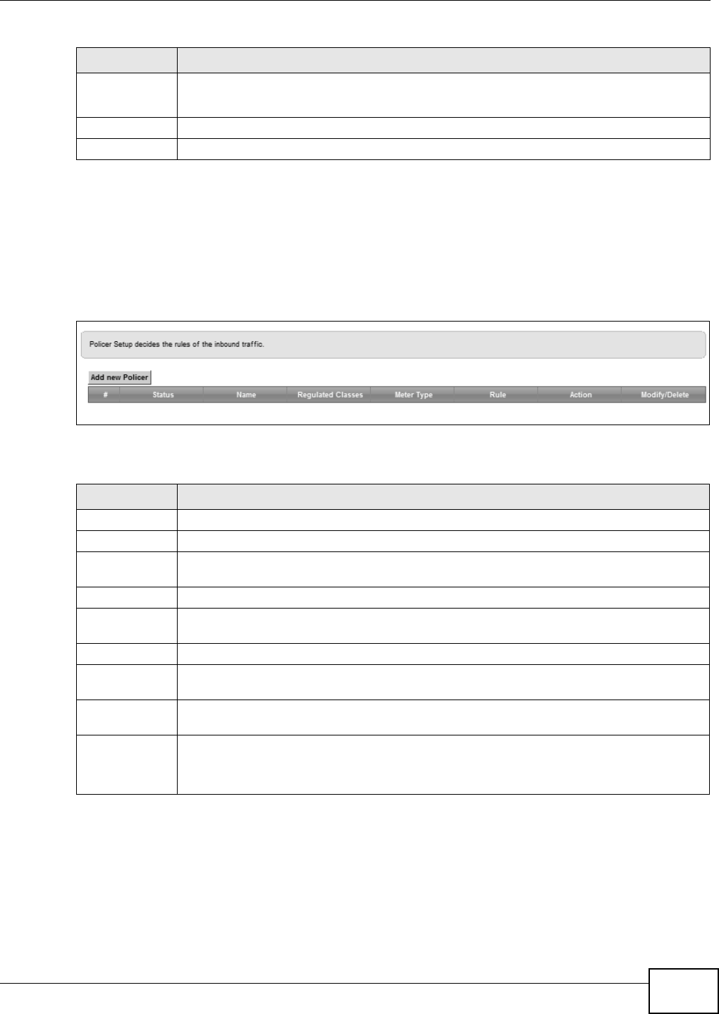
Chapter 9 Quality of Service (QoS)
VMG8324-B10A / VMG8324-B30A Series User’s Guide 149
9.6 The QoS Policer Setup Screen
Use t his scr een t o configure QoS policers t hat allow you to lim it t he t ransm ission rate of incom ing
traffic. Click N et w ork Set t ing > QoS > Policer Se t up. The screen appear s as show n.
Figure 79 Net work Set t ing > QoS > Policer Set up
The following t able describes t he labels in this screen.
To Queue I ndex Select a queue t hat applies to t his class.
You should have configured a queue in t he Que ue Se t up screen already.
Apply Click Apply t o save your changes.
Cancel Click Ca ncel t o exit t his screen wit hout saving.
Table 51 Class Set up: Add/ Edit ( cont inued)
LABEL DESCRIPTION
Table 52 Net work Set ting > QoS > Policer Set up
LABEL DESCRIPTION
Add new Policer Click this t o create a new entry.
#This is t he index num ber of t he entry.
St atus This field display s whether t he policer is act ive or not . A yellow bulb signifies t hat t his
policer is active. A gray bulb signifies that this policer is not active.
Nam e This field displays t he descript ive nam e of t his policer.
Regulat ed
Classes
This field display s t he nam e of a QoS classifier
Met er Type This field displays t he t ype of QoS m etering algorit hm used in t his policer.
Rule These are t he rat es and burst sizes against which t he policer checks t he t raffic of t he
m em ber QoS classes.
Act ion This shows t he how t he policer has t he Device treat differ ent types of traffic belonging t o
the policer’s m em ber QoS classes.
Modify Click t he Ed it icon to edit t he policer.
Click the D ele t e icon to delet e an exist ing policer. Not e t hat subsequent rules m ove up by
one when you t ake this action.
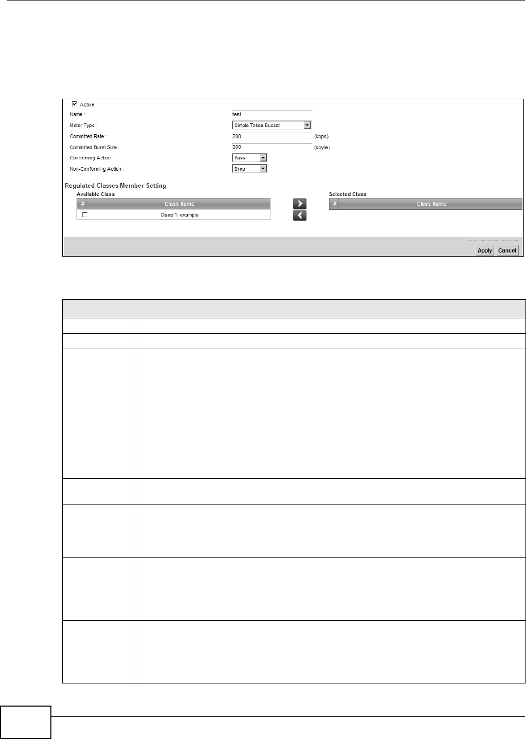
Chapter 9 Quality of Service (QoS)
VMG8324-B10A / VMG8324-B30A Series User’s Guide
150
9.6.1 Add/Edit a QoS Policer
Click Add new Policer in t he Police r Se t u p screen or the Ed it icon next to a policer t o show the
following screen.
Figure 80 Policer Setup: Add/ Edit
The following t able describes t he labels in this screen.
Table 53 Policer Set up: Add/ Edit
LABEL DESCRIPTION
Act ive Select the check box to act ivat e t his policer.
Nam e Ent er the descript ive nam e of t his policer.
Met er Type This show s t he t raffic m etering algorit hm used in this policer.
The Sim ple Toke n Buck et alg or it h m u ses t ok en s in a bu ck et t o cont r ol w h en t r affic can b e
transm itt ed. Each token represent s one byt e. The algorithm allows bursts of up t o b by t es
which is also t he bucket size.
The Single Ra t e Thre e Color Mark e r ( srTCM) is based on t he t oken bucket filt er and
ident ifies packets by com paring them t o t he Com m it t ed I nform at ion Rat e ( CI R), t he
Com m it t ed Burst Size ( CBS) and the Excess Burst Size ( EBS) .
The Tw o Ra t e Th ree Color Mark e r ( t rTCM) is based on t he t oken bucket filt er and
identifies packet s by com paring t hem to the Com m itted I nfor m ation Rat e ( CI R) and t he
Peak I nform at ion Rate ( PI R).
Com m it ted
Rat e
Specify t he com m itt ed rat e. When the incom ing t raffic rat e of the m em ber QoS classes is
less than t he com m it t ed rat e, t he device applies t he conform ing act ion t o t he t raffic.
Com m it ted
Burst Size
Specify the com m it t ed bur st size for packet burst s. This m ust be equal t o or less t han the
peak burst size (two rat e t hree color) or excess burst size ( single rate t hree color ) if it is also
configured.
This is t he m axim um size of t he ( first ) t oken bucket in a t raffic m et ering algorithm .
Conform ing
Act ion
Specify what t he Device does for packet s wit hin the com m it t ed rate and burst size ( green-
m arked packet s) .
•Pa ss: Send t he packet s wit hout m odificat ion.
•DSCP Mar k : Change the DSCP m ark value of the packet s. Ent er the DSCP m ark value t o
use.
Non-
Conform ing
Act ion
Specify what the Device does for packet s that exceed the excess burst size or peak rat e and
bur st size ( red-m ar ked packets) .
•Dr op: Discar d t he packets.
•DSCP Mar k : Change the DSCP m ark value of the packet s. Ent er the DSCP m ark value t o
use. The packet s m ay be dropped if t here is congest ion on t he net work.
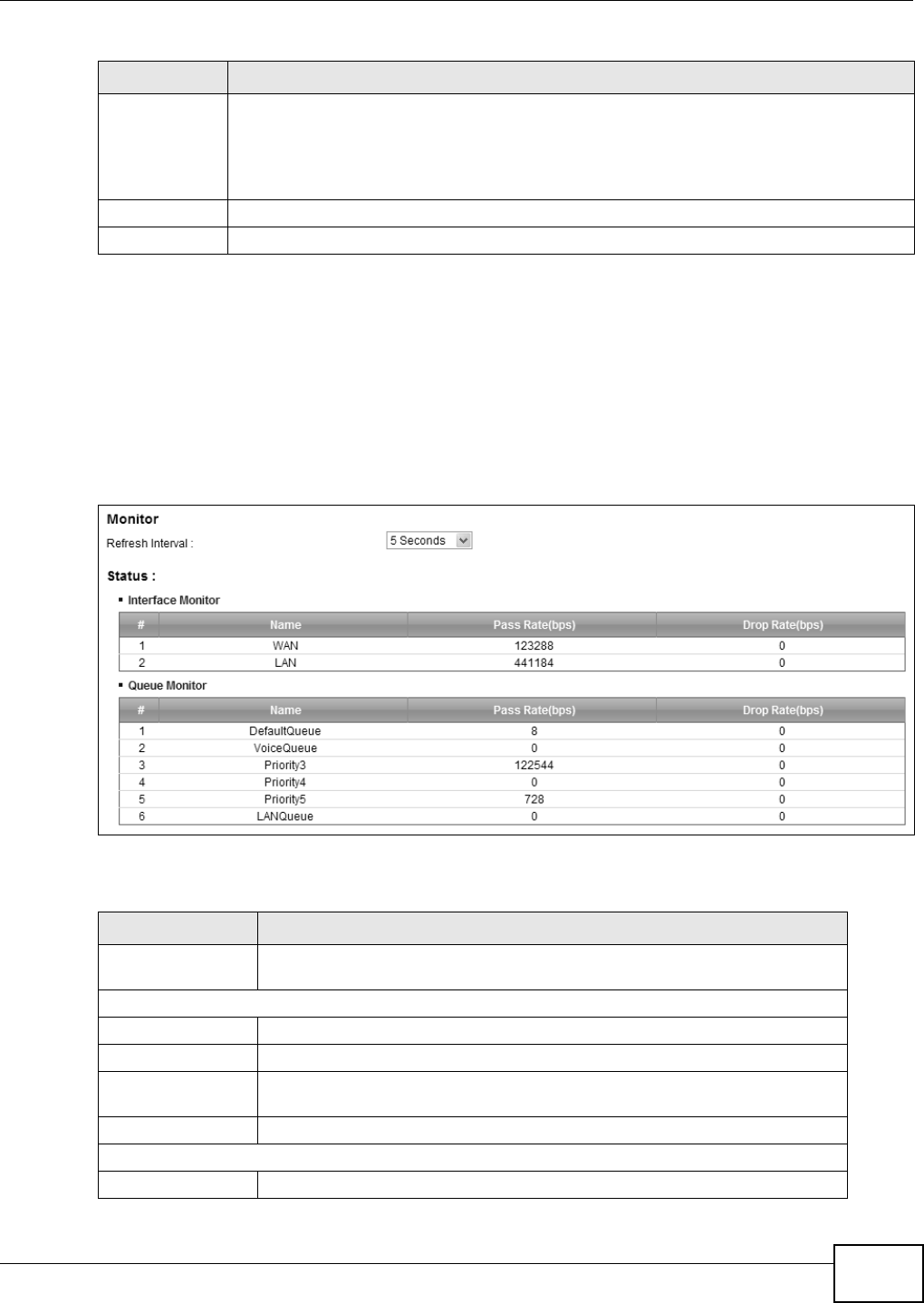
Chapter 9 Quality of Service (QoS)
VMG8324-B10A / VMG8324-B30A Series User’s Guide 151
9.7 The QoS Monitor Screen
This screen is available only when you set a rat e lim it for a WAN queue in t he Qu e u e Se t up screen
and t he WAN int erface is connect ed. Use t his scr een to m onit or t he t raffic st atist ics for both t he
WAN and LAN int erfaces. To view t he Device’s QoS packet stat ist ics, click N e t w or k Se t t ing > QoS
> M onit or. The screen appears as shown.
Figure 81 Net work Set t ing > QoS > Monit or
The following t able describes t he labels in this screen.
Available Class
Selected Class
Select a QoS classifier t o apply this QoS policer t o t raffic t hat m at ches the QoS classifier.
Highlight a QoS classifier in the Availa ble Cla ss box and use the > b u t t on t o m ove it t o t h e
Select ed Cla ss box.
To rem ove a QoS classifier from t he Select ed Cla ss box, select it and use the < but t on.
Apply Click Apply to save your changes.
Cancel Click Cance l t o exit t his screen wit hout saving.
Table 53 Policer Set up: Add/ Edit
LABEL DESCRIPTION
Table 54 Net work Sett ing > QoS > Monit or
LABEL DESCRIPTION
Refresh I nt erval Ent er how oft en you want t he Device t o updat e t his screen. Select No Refresh
to st op refreshing st at ist ics.
I nterface Monitor
# This is t he index num ber of t he entry.
Nam e This shows t he nam e of t he interface on t he Device.
Pass Rat e This shows how m any packet s forwarded t o t his int erface are transm itted
successfully.
Drop Rat e This shows how m any packet s for warded t o t his int erface are dropped.
Queue Monit or
# This is t he index num ber of t he entry.

Chapter 9 Quality of Service (QoS)
VMG8324-B10A / VMG8324-B30A Series User’s Guide
152
9.8 Technical Reference
The following sect ion cont ains additional t echnical inform ation about the Device feat ures described
in this chapt er.
IEEE 802.1Q Tag
The I EEE 802.1Q st andard defines an explicit VLAN t ag in t he MAC header to identify the VLAN
m em bership of a fram e across bridges. A VLAN t ag includes t he 12-bit VLAN I D and 3- bit user
priority. The VLAN I D associat es a fram e wit h a specific VLAN and provides the inform at ion t hat
devices need t o process t he fram e across t he net work.
I EEE 802.1p specifies t he user priorit y field and defines up t o eight separate t raffic t ypes. The
following table describes t he t raffic types defined in t he I EEE 802.1d st andard ( which incorporat es
the 802.1p).
DiffServ
QoS is used to prioritize source-t o- dest ination traffic flows. All packets in t he flow are given t he
sam e priorit y. You can use CoS ( class of service) t o give different priorities to differ ent packet
types.
DiffServ ( Differentiat ed Services) is a class of ser vice ( CoS) m odel t hat m arks packet s so t hat t hey
receive specific per- hop t reat m ent at DiffServ- com pliant net w ork devices along t he rout e based on
the applicat ion types and traffic flow. Packet s are m arked with DiffServ Code Point s ( DSCPs)
Nam e This shows t he nam e of t he queue.
Pass Rat e This shows how m any pack et s assigned t o t his queue ar e t ransm it t ed
successfully.
Drop Rat e This shows how m any packets assigned to this queue are dropped.
Table 54 Net work Sett ing > QoS > Monit or ( continued)
LABEL DESCRIPTION
Table 55 I EEE 802.1p Pr iority Level and Traffic Type
PRIORITY
LEVEL TRAFFIC TYPE
Level 7 Typically used for network contr ol t raffic such as router configuration m essages.
Level 6 Typically used for voice traffic t hat is especially sensit ive t o j it t er ( j it t er is the
variat ions in delay) .
Level 5 Typically used for video t hat consum es high bandwidt h and is sensitive to j it t er.
Level 4 Typically used for cont rolled load, lat ency- sensit ive t raffic such as SNA ( Syst em s
Networ k Archit ect ure) transact ions.
Level 3 Typically used for “ excellent effort ” or bet t er than best effort and would include
im port ant business traffic that can t olerate som e delay.
Level 2 This is for “ spare bandwidt h”.
Level 1 This is typically used for non- crit ical “ background” traffic such as bulk t ransfers that
are allowed but that should not affect other applicat ions and users.
Level 0 Typically used for best - effort traffic.

Chapter 9 Quality of Service (QoS)
VMG8324-B10A / VMG8324-B30A Series User’s Guide 153
indicat ing t he level of service desired. This allows the int erm ediary DiffServ- com pliant net work
devices to handle t he packet s different ly depending on t he code points wit hout t he need t o
negotiate paths or rem em ber stat e inform at ion for every flow. I n addit ion, applications do not have
to request a particular service or give advanced notice of w here the traffic is going.
DSCP and Per-Hop Behavior
DiffServ defines a new Differentiat ed Services ( DS) field t o replace the Type of Service ( TOS) field
in t he I P header. The DS field cont ains a 2- bit unused field and a 6- bit DSCP field which can define
up t o 64 ser vice levels. The following figure illust rat es t he DS field.
DSCP is backward com pat ible wit h t he t hree precedence bits in t he ToS oct et so t hat non- DiffServ
com pliant, ToS- enabled net work device will not conflict wit h t he DSCP m apping.
The DSCP value det erm ines t he forwarding behavior, the PHB ( Per- Hop Behavior), t hat each packet
get s across the DiffServ network. Based on t he m arking rule, different kinds of t raffic can be
m arked for different kinds of forwarding. Resources can t hen be allocated according t o the DSCP
values and the configured policies.
IP Precedence
Sim ilar t o I EEE 802.1p priorit ization at layer- 2, you can use I P precedence to prioritize packets in a
layer- 3 net work. I P precedence uses t hree bit s of t he eight- bit ToS (Type of Service) field in t he I P
header. There are eight classes of services ( ranging fr om zero t o seven) in I P precedence. Zero is
the lowest priority level and seven is t he highest .
Automatic Priority Queue Assignment
I f you enable QoS on t he Device, the Device can aut om at ically base on t he I EEE 802.1p priorit y
level, I P precedence and/ or packet lengt h t o assign priorit y to t raffic which does not m at ch a class.
The following t able shows you t he internal layer- 2 and layer- 3 QoS m apping on t he Device. On the
Device, t raffic assigned t o higher priority queues get s t hrough fast er while traffic in lower index
queues is dropped if the net work is congest ed.
DSCP ( 6 bit s) Unused ( 2 bit s)
Table 56 I nt ernal Layer2 and Layer3 QoS Mapping
PRIORITY
QUEUE
LAYER 2 LAYER 3
IEEE 802.1P USER
PRIORITY
(ETHERNET
PRIORITY)
TOS (IP
PRECEDENCE) DSCP IP PACKET
LENGTH (BYTE)
0 1 0 000000
12
2 0 0 000000 > 1100
3 3 1 001110
001100
001010
001000
250~ 1100

Chapter 9 Quality of Service (QoS)
VMG8324-B10A / VMG8324-B30A Series User’s Guide
154
Token Bucket
The t oken bucket algorithm uses t okens in a bucket t o cont rol when t raffic can be transm it ted. The
bucket st ores t okens, each of w hich represent s one byt e. The algorit hm allows burst s of up t o b
byt es which is also the bucket size, so t he bucket can hold up t o b t okens. Tokens are generat ed
and added into t he bucket at a const ant rate. The following shows how t okens work with packets:
• A packet can be t ransm it t ed if t he num ber of t okens in t he bucket is equal to or great er t han t he
size of the packet ( in byt es) .
• Aft er a packet is t ransm it ted, a num ber of tokens corresponding t o t he packet size is rem oved
from t he bucket .
• I f t here are no t okens in t he bucket , the Device st ops transm it ting unt il enough t okens are
generat ed.
• I f not enough t okens are available, t he Device t reat s the packet in either one of t he following
ways:
I n t raffic shaping:
• Holds it in t he queue unt il enough t okens are available in t he bucket.
I n t raffic policing:
• Drops it.
• Transm it s it but adds a DSCP m ar k. The Device m ay drop these m arked packet s if the net w ork
is overloaded.
4 4 2 010110
010100
010010
010000
5 5 3 011110
011100
011010
011000
< 250
6 6 4 100110
100100
100010
100000
5 101110
101000
7 7 6 110000
111000
7
Table 56 I nt ernal Layer2 and Layer3 QoS Mapping
PRIORITY
QUEUE
LAYER 2 LAYER 3
IEEE 802.1P USER
PRIORITY
(ETHERNET
PRIORITY)
TOS (IP
PRECEDENCE) DSCP IP PACKET
LENGTH (BYTE)

Chapter 9 Quality of Service (QoS)
VMG8324-B10A / VMG8324-B30A Series User’s Guide 155
Configure the bucket size to be equal to or less t han the am ount of t he bandw idth t hat t he int erface
can support . I t does not help if you set it t o a bucket size over t he int erface’s capabilit y. The sm aller
the bucket size, t he lower t he data transm ission rat e and that m ay cause out going packet s t o be
dropped. A larger t ransm ission rate r equires a big bucket size. For exam ple, use a bucket size of 10
kbyt es t o get the transm ission rat e up to 10 Mbps.
Single Rate Three Color Marker
The Single Rate Three Color Marker ( srTCM, defined in RFC 2697) is a t ype of t raffic policing that
identifies packets by com paring them t o one user- defined rate, t he Com m it t ed I nform ation Rat e
( CI R), and t wo burst sizes: t he Com m it t ed Burst Size ( CBS) and Excess Burst Size ( EBS) .
The srTCM evaluat es incom ing packets and m arks t hem wit h one of t hree colors which refer to
packet loss priority levels. High packet loss priority level is referred t o as red, m edium is referred to
as yellow and low is referr ed to as green.
The srTCM is based on t he t oken bucket filt er and has two token buckets ( CBS and EBS). Tokens
are generat ed and added int o t he bucket at a const ant rate, called Com m itt ed I nform at ion Rat e
( CI R). When t he first bucket ( CBS) is full, new t okens overflow into the second bucket (EBS) .
All packet s are evaluated against t he CBS. I f a packet does not exceed the CBS it is m arked green.
Ot herwise it is evaluat ed against t he EBS. I f it is below t he EBS then it is m arked yellow. I f it
exceeds t he EBS then it is m arked red.
The following shows how tokens wor k wit h incom ing packet s in srTCM:
• A packet arr ives. The packet is m arked green and can be transm it t ed if t he num ber of tokens in
the CBS bucket is equal to or great er than t he size of t he packet ( in byt es).
• Aft er a packet is t ransm it ted, a num ber of tokens corresponding t o t he packet size is rem oved
from t he CBS bucket .
• I f t here are not enough tokens in t he CBS bucket , t he Device checks t he EBS bucket . The packet
is m arked yellow if there are sufficient t okens in the EBS bucket. Ot herwise, t he packet is m arked
red. No t okens are rem oved if the packet is dropped.
Two Rate Three Color Marker
The Two Rat e Thr ee Color Marker ( t rTCM, defined in RFC 2698) is a type of traffic policing t hat
identifies packets by com paring them t o t wo user- defined rat es: t he Com m it t ed I nform at ion Rate
( CI R) and t he Peak I nform ation Rat e ( PI R) . The CIR specifies t he average rate at which packet s are
adm itt ed to the net w ork. The PI R is great er t han or equal t o the CI R. CI R and PI R values are based
on t he guaranteed and m axim um bandwidt h respect ively as negot iat ed bet w een a service provider
and client .
The t rTCM evaluat es incom ing packets and m arks t hem wit h one of t hree colors which refer to
packet loss priority levels. High packet loss priority level is referred t o as red, m edium is referred to
as yellow and low is referr ed to as green.
The t rTCM is based on t he t oken bucket filt er and has t wo token bucket s ( Com m itt ed Burst Size
( CBS) and Peak Burst Size ( PBS) ) . Tokens are generat ed and added into the two bucket s at t he CI R
and PI R respect ively.

Chapter 9 Quality of Service (QoS)
VMG8324-B10A / VMG8324-B30A Series User’s Guide
156
All packet s ar e evaluat ed against t he PI R. I f a packet exceeds t he PI R it is m arked red. Ot herwise it
is evaluated against t he CI R. I f it exceeds t he CIR then it is m arked yellow. Finally, if it is below t he
CIR then it is m arked green.
The following shows how tokens wor k wit h incom ing packet s in trTCM:
• A packet ar r iv es. I f t h e n u m ber of t okens in t he PBS bucket is less t han t he size of t he packet ( in
byt es) , t he packet is m arked red and m ay be dropped regardless of t he CBS bucket . No tokens
are rem oved if t he packet is dropped.
• I f t he PBS bucket has enough t okens, t he Device checks t he CBS bucket . The packet is m arked
green and can be t ransm itt ed if t he num ber of tokens in t he CBS bucket is equal to or great er
than the size of t he packet (in byt es) . Ot herwise, t he packet is m arked yellow.

VMG8324-B10A / VMG8324-B30A Series User’s Guide 157
CHAPTER 10
Network Address Translation (NAT)
10.1 Overview
This chapt er discusses how to configure NAT on t he Device. NAT ( Net work Address Translation -
NAT, RFC 1631) is t he t ranslation of t he I P address of a host in a packet , for exam ple, t he sour ce
address of an out going packet , used wit hin one net work to a different I P address known wit hin
another network.
10.1.1 What You Can Do in this Chapter
• Use the Port For w arding screen t o configure forward incom ing service requests t o t he server( s)
on your local network ( Sect ion 10.2 on page 158) .
• Use the Ap plica t ion s scr een t o forward incom ing service requests to the server(s) on your local
net work ( Sect ion 10.3 on page 161) .
• Use the Port Trigge r ing screen t o add and configure the Device’s t rigger port sett ings ( Sect ion
10.4 on page 162) .
• Use the D M Z screen to configure a default server (Section 10.5 on page 165) .
• Use the ALG screen to enable and disable t he NAT and SI P (VoI P) ALG in the Device (Sect ion
10.6 on page 166) .
• Use the Address M apping screen to configure the Device's addr ess m apping set t ings ( Sect ion
10.7 on page 166) .
• Use the Sessions screen to configure the Device's m axim um num ber of NAT sessions (Sect ion
10.7 on page 166) .
10.1.2 What You Need To Know
Inside/Outside
I nside/ outside denot es where a host is locat ed relat ive t o t he Device, for exam ple, t he com put ers
of your subscribers are the inside host s, while t he web servers on t he I nt ernet are t he out side
host s.
Global/Local
Global/ local denot es t he I P address of a host in a packet as t he packet t raverses a rout er, for
exam ple, t he local address refers t o the I P address of a host when the packet is in t he local
net work, while t he global address refers to the I P address of t he host when t he sam e packet is
traveling in t he WAN side.

Chapter 10 Network Address Translation (NAT)
VMG8324-B10A / VMG8324-B30A Series User’s Guide
158
NAT
I n t he sim plest form , NAT changes t he source I P address in a packet received from a subscriber
( t he inside local addr ess) t o another ( t he inside global address) before forwarding t he packet t o t he
WAN side. When the response com es back, NAT translates t he dest inat ion addr ess ( t he inside
global address) back t o t he inside local addr ess before forwarding it to the original inside host .
Port Forwarding
A port forwarding set is a list of inside ( behind NAT on the LAN) servers, for exam ple, web or FTP,
that you can m ake visible t o t he out side wor ld even though NAT m akes your whole inside network
appear as a single com put er t o t he out side world.
Finding Out More
See Sect ion 10.10 on page 169 for advanced technical inform ation on NAT.
10.2 The Port Forwarding Screen
Use t he Por t For w a rding screen t o forward incom ing service r equest s to the server( s) on your
local net work.
You m ay ent er a single port num ber or a range of port num bers t o be forwarded, and the local I P
address of t he desired ser ver. The port num ber ident ifies a service; for exam ple, web service is on
port 80 and FTP on port 21. I n som e cases, such as for unknown services or where one server can
support m ore t han one service ( for exam ple bot h FTP and web service) , it m ight be bet t er t o
specify a range of port num bers. You can allocate a ser ver I P address t hat cor responds t o a port or
a range of port s.
The m ost oft en used port num bers and services are shown in Appendix G on page 397. Please refer
to RFC 1700 for fur t her inform ation about port num bers.
Not e: Many residential broadband I SP account s do not allow you t o run any server
processes ( such as a Web or FTP server) from your locat ion. Your I SP m ay
periodically check for servers and m ay suspend your account if it discovers any
act ive services at your location. I f you are unsure, refer to your I SP.
Configuring Servers Behind Port Forwarding (Example)
Let 's say you want to assign port s 21- 25 to one FTP, Telnet and SMTP server (A in t he exam ple) ,
port 80 t o anot her ( B in the exam ple) and assign a default server I P address of 192.168.1.35 t o a
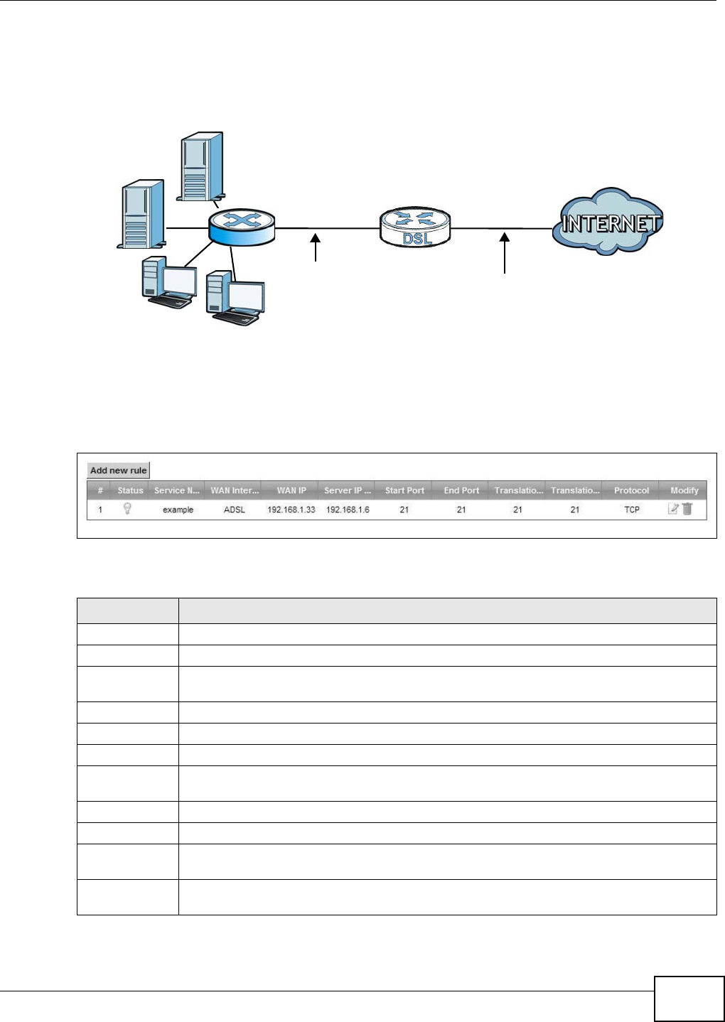
Chapter 10 Network Address Translation (NAT)
VMG8324-B10A / VMG8324-B30A Series User’s Guide 159
third (C in t he exam ple) . You assign the LAN I P addresses and t he I SP assigns the WAN I P address.
The NAT network appears as a single host on t he I nt ernet .
Figure 82 Mult iple Servers Behind NAT Exam ple
Click N et w ork Sett ing > N AT > Port Forw arding t o open t he following screen.
See Appendix G on page 397 for port num bers com m only used for part icular services.
Figure 83 Net work Set t ing > NAT > Port Forwarding
The following t able describes t he fields in t his screen.
Table 57 Net work Set t ing > NAT > Port Forwarding
LABEL DESCRIPTION
Add new rule Click t his t o add a new rule.
#This is t he index num ber of t he entry.
St atus This field displays whether t he NAT rule is act ive or not. A yellow bulb signifies that this rule
is active. A gray bulb signifies that t his rule is not act ive.
Service Nam e This shows t he service’s nam e.
WAN I nt erface This show s t he WAN int erface t hrough which t he service is for war ded.
WAN I P This field display s t he incom ing packet ’s dest inat ion I P address.
Server I P
Address
This is t he server ’s I P address.
St art Port This is t he first ext ernal port num ber t hat ident ifies a service.
End Port This is t he last exter nal por t num ber that identifies a service.
Tr an sl a t i on
St art Port
This is t he first int ernal port num ber t hat ident ifies a service.
Tr a n s l a t i o n En d
Port
This is t he last int ernal port num ber t hat ident ifies a service.
A=192.168.1.33
D=192.168.1.36
C=192.168.1.3
B=192.168.1.34
WAN
LAN
192.168.1.1 IP Address assigned by ISP
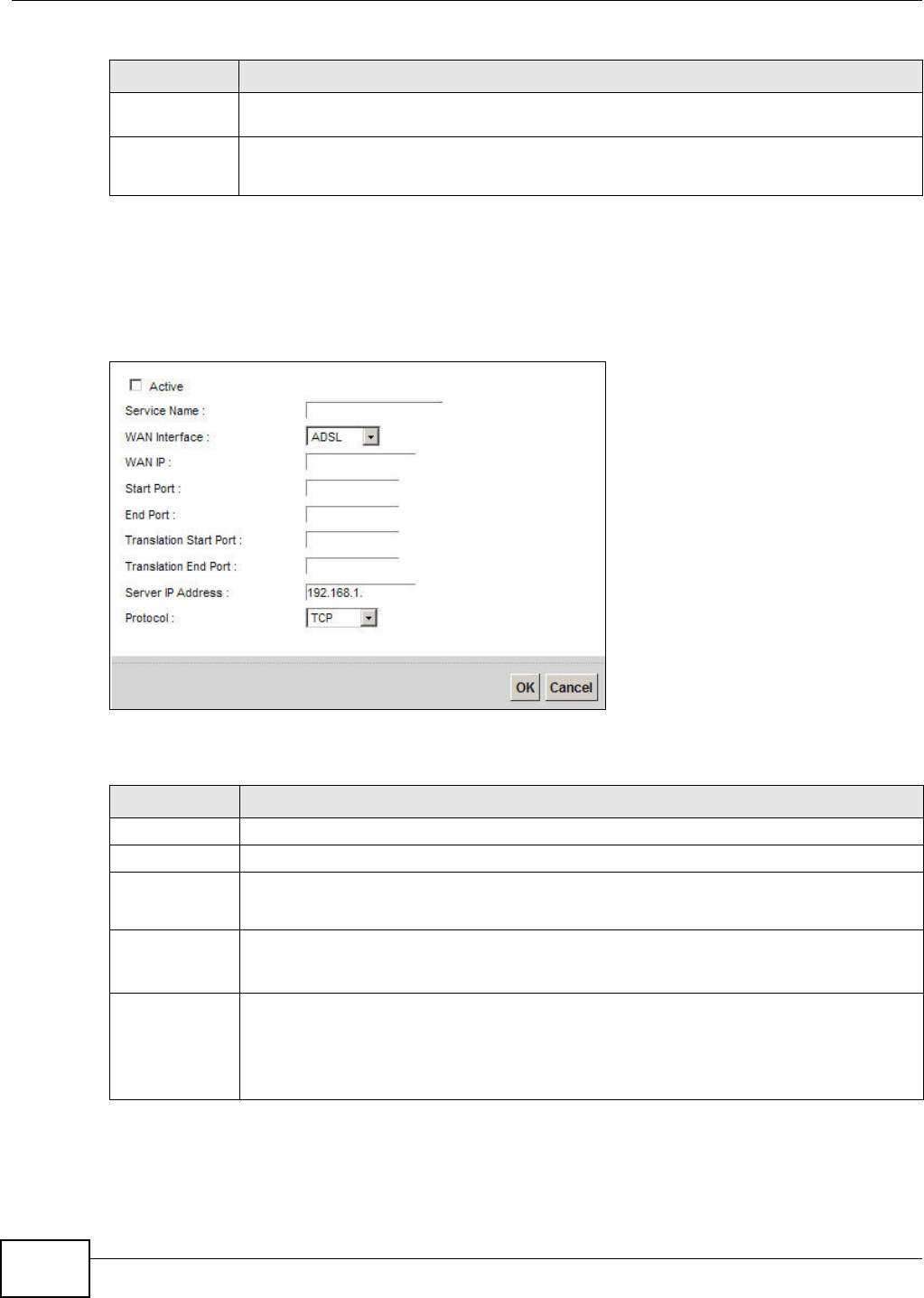
Chapter 10 Network Address Translation (NAT)
VMG8324-B10A / VMG8324-B30A Series User’s Guide
160
10.2.1 Add/Edit Port Forwarding
Click Add ne w rule in the Port For w ar ding screen or click the Ed it icon next t o an existing rule to
open the following screen.
Figure 84 Port Forwarding: Add/ Edit
The following t able describes t he labels in this screen.
Prot ocol This shows t he I P protocol support ed by t his virt ual server, whet her it is TCP, UD P, or TCP/
UDP.
Modify Click the Ed it icon t o edit t his rule.
Click t he D e le t e icon t o delete an exist ing rule.
Table 57 Net work Sett ing > NAT > Port Forwarding ( continued)
LABEL DESCRIPTION
Table 58 Port Forwar ding: Add/ Edit
LABEL DESCRIPTION
Act ive Clear t he check box t o disable t he rule. Select t he check box t o enable it .
Service Nam e Enter a nam e t o identify this rule using keyboard characters ( A-Z, a-z, 1- 2 and so on).
WAN I nt erface Select t he WAN int erface t hrough which t he serv ice is forwarded.
You m ust have already configured a WAN connect ion wit h NAT enabled.
WAN I P Ent er the WAN I P address for which t he incom ing service is dest ined. I f t he packet ’s
dest ination I P address doesn’t m atch t he one specified here, the port forwarding rule will
not be applied.
St art Port Ent er the original dest inat ion port for t he packet s.
To forward only one port , ent er the por t num ber again in t he En d Port field.
To forward a series of port s, enter t he st art port num ber here and t he end port num ber in
the End Port field.
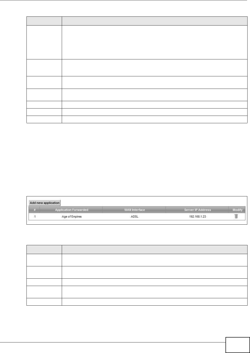
Chapter 10 Network Address Translation (NAT)
VMG8324-B10A / VMG8324-B30A Series User’s Guide 161
10.3 The Applications Screen
This screen provides a sum m ary of all NAT applications and t heir configurat ion. I n addition, this
screen allows you t o creat e new applicat ions and/ or rem ove existing ones.
To access t his screen, click N e t w or k Se t t ing > N AT > Applica t ion s. The following screen
appears.
Figure 85 Net work Set t ing > NAT > Applications
The following t able describes t he labels in this screen.
End Port Enter t he last port of t he original dest ination port range.
To forward only one port , ent er the port num ber in t he St a rt Port field above and t hen
enter it again in this field.
To forward a ser ies of port s, ent er t he last port num ber in a ser ies t hat begins w it h t he por t
num ber in the St a rt Por t field above.
Tr an sl a t i on
St art Port
This show s the por t num ber to which you want t he Dev ice t o t ranslat e t he incom ing port.
For a range of port s, ent er t he fir st num ber of the range t o w hich you want t he incom ing
port s translat ed.
Tr a n s l a t i o n En d
Port
This shows t he last port of t he t ranslated port range.
Server I P
Address
Ent er t he inside I P address of the virt ual server here.
Prot ocol Select the pr ot ocol support ed by this virtual ser ver. Choices are TCP, UD P, or TCP/ UDP.
OK Click OK to save your changes.
Cancel Click Ca nce l t o exit t his screen w it hout saving.
Table 58 Port Forwar ding: Add/ Edit ( cont inued)
LABEL DESCRIPTION
Table 59 Net work Sett ing > NAT > Applicat ions
LABEL DESCRIPTION
Add new
applicat ion
Click t his t o add a new NAT applicat ion rule.
Applicat ion
Forwarded
This field shows t he t ype of application t hat t he service for wards.
WAN I nt erface This field shows the WAN interface through which the service is forwarded.
Server I P
Address
This field displays the dest ination I P address for t he service.
Modify Click t he D e let e icon t o delet e t he rule.
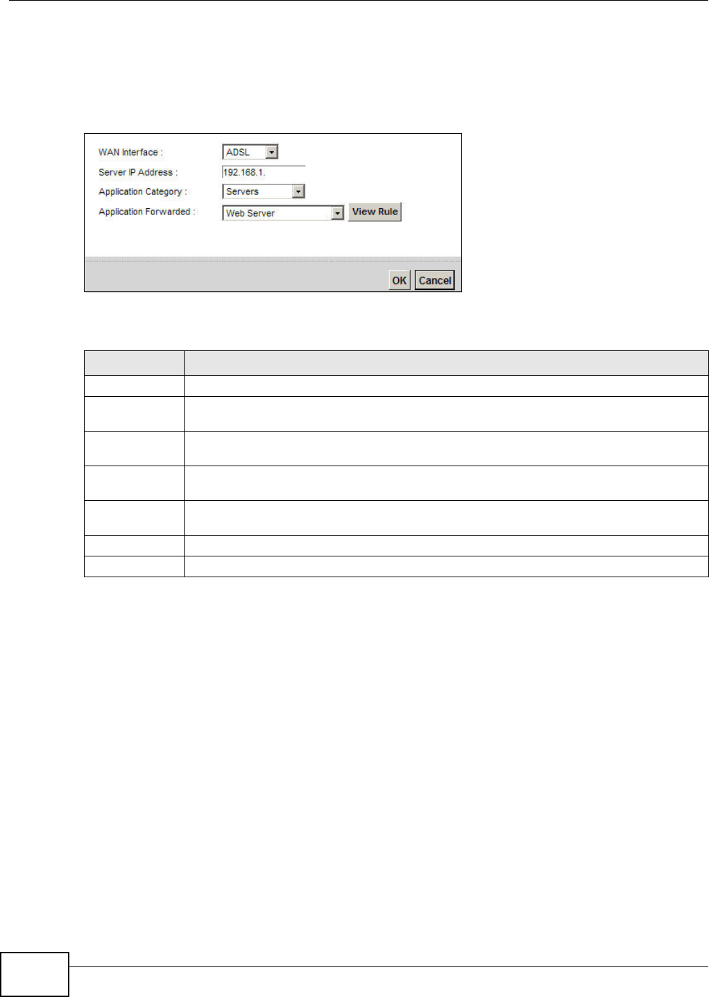
Chapter 10 Network Address Translation (NAT)
VMG8324-B10A / VMG8324-B30A Series User’s Guide
162
10.3.1 Add New Application
This screen lets you creat e new NAT applicat ion rules. Click Add new a pplica t ion in the
Applica t ions screen to open the following screen.
Figure 86 Applicat ions: Add
The following t able describes t he labels in this screen.
10.4 The Port Triggering Screen
Som e services use a dedicat ed range of port s on the client side and a dedicat ed range of port s on
the server side. Wit h regular port forwarding you set a forwarding port in NAT t o forward a service
( com ing in from the server on the WAN) t o t he I P address of a com put er on the client side ( LAN) .
The problem is t hat port forwarding only forwards a service t o a single LAN I P address. I n order t o
use t he sam e service on a different LAN com put er, you have t o m anually replace the LAN
com put er's I P address in the forwarding port with anot her LAN com put er's I P address.
Trigger port forwarding solves this problem by allowing com put ers on t he LAN t o dynam ically take
turns using the service. The Device records the I P address of a LAN com put er t hat sends traffic t o
the WAN to request a ser vice with a specific port num ber and prot ocol ( a "trigger" port ) . When t he
Device's WAN port receives a response wit h a specific port num ber and protocol ( "open" por t ) , t he
Device forwar ds t he t raffic t o t he LAN I P address of the com put er t hat sent t he request . After t hat
com put er’s connection for t hat service closes, anot her com puter on t he LAN can use the service in
the sam e m anner. This way you do not need to configur e a new I P address each tim e you want a
different LAN com put er t o use the applicat ion.
Table 60 Applications: Add
LABEL DESCRIPTION
WAN I nt erface Select t he WAN int erface t hat you want to apply this NAT rule t o.
Server I P
Address
Ent er t he inside I P address of the applicat ion here.
Applicat ion
Category
Select t he category of the applicat ion from the dr op- down list box.
Applicat ion
Forwarded
Select a service from the drop- down list box and the Device aut om at ically configures t he
pr ot ocol, st art , end, and m ap port num ber t hat define t he ser vice.
View Rule Click t his t o display t he configurat ion of t he serv ice t hat you have chosen in Applica t ion
Fow ar de d.
OK Click OK to save your changes.
Cancel Click Ca nce l t o exit t his screen w it hout saving.
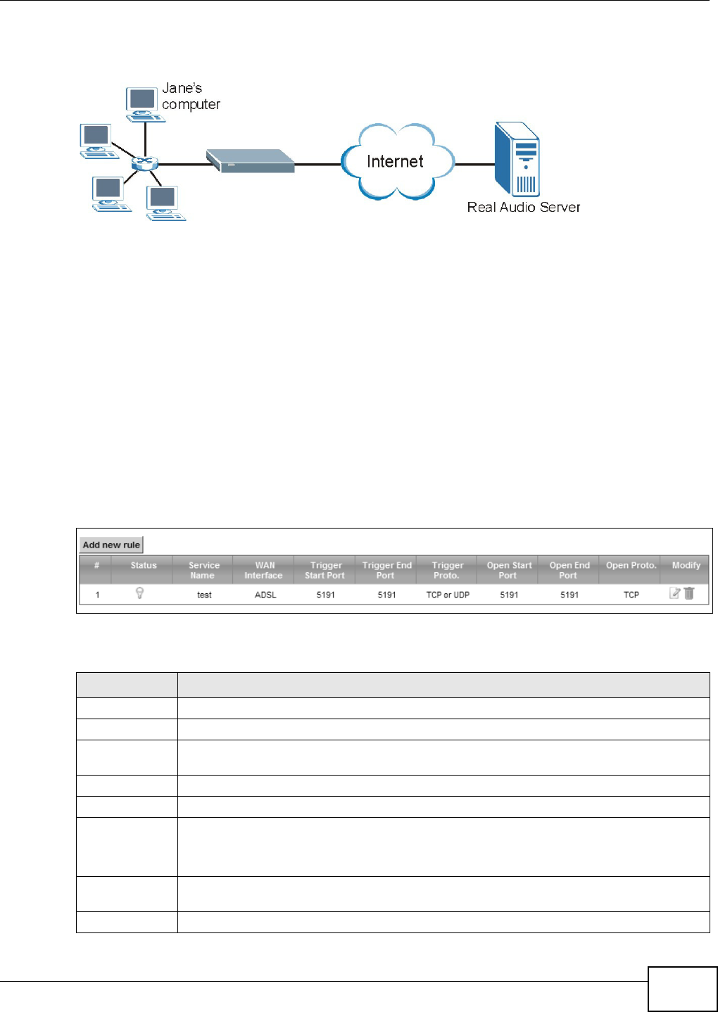
Chapter 10 Network Address Translation (NAT)
VMG8324-B10A / VMG8324-B30A Series User’s Guide 163
For exam ple:
Figure 87 Trigger Port Forwarding Process: Exam ple
1Jane request s a file from t he Real Audio server ( port 7070) .
2Port 7070 is a “ t rigger ” port and causes the Device t o record Jane’s com puter I P address. The
Device associat es Jane's com put er I P address wit h t he " open" port range of 6970- 7170.
3The Real Audio server responds using a port num ber ranging between 6970- 7170.
4The Device forwards t he traffic t o Jane’s com puter I P address.
5Only Jane can connect t o t he Real Audio server until t he connect ion is closed or tim es out. The
Device tim es out in t hree m inutes with UDP (User Datagram Prot ocol) or t wo hours wit h TCP/ I P
( Transfer Cont rol Prot ocol/ I nternet Protocol) .
Click N e t w or k Se t t ing > N AT > Por t Trigge r ing to open the following screen. Use t his screen t o
view your Device’s t rigger port set t ings.
Figure 88 Net work Set t ing > NAT > Port Triggering
The following t able describes t he labels in this screen.
Table 61 Net work Sett ing > NAT > Port Triggering
LABEL DESCRIPTION
Add new rule Click t his t o creat e a new rule.
#This is t he index num ber of t he entry.
St atus This field display s whet her t he port t rigger ing rule is act ive or not . A yellow bulb signifies
that this rule is active. A gray bulb signifies t hat t his r ule is not active.
Service Nam e This field displays the nam e of t he ser vice used by t his rule.
WAN I nt erface This field shows the WAN interface through which the service is forwarded.
Trigger St art
Port
The t rigger port is a port ( or a range of port s) that causes ( or triggers) t he Device to record
t he I P address of the LAN com put er that sent the traffic t o a server on t he WAN.
This is t he first port num ber t hat ident ifies a serv ice.
Trigger End
Port
This is t he last por t num ber t hat ident ifies a service.
Trigger Prot o. This is t he t r igger t ransport layer prot ocol.
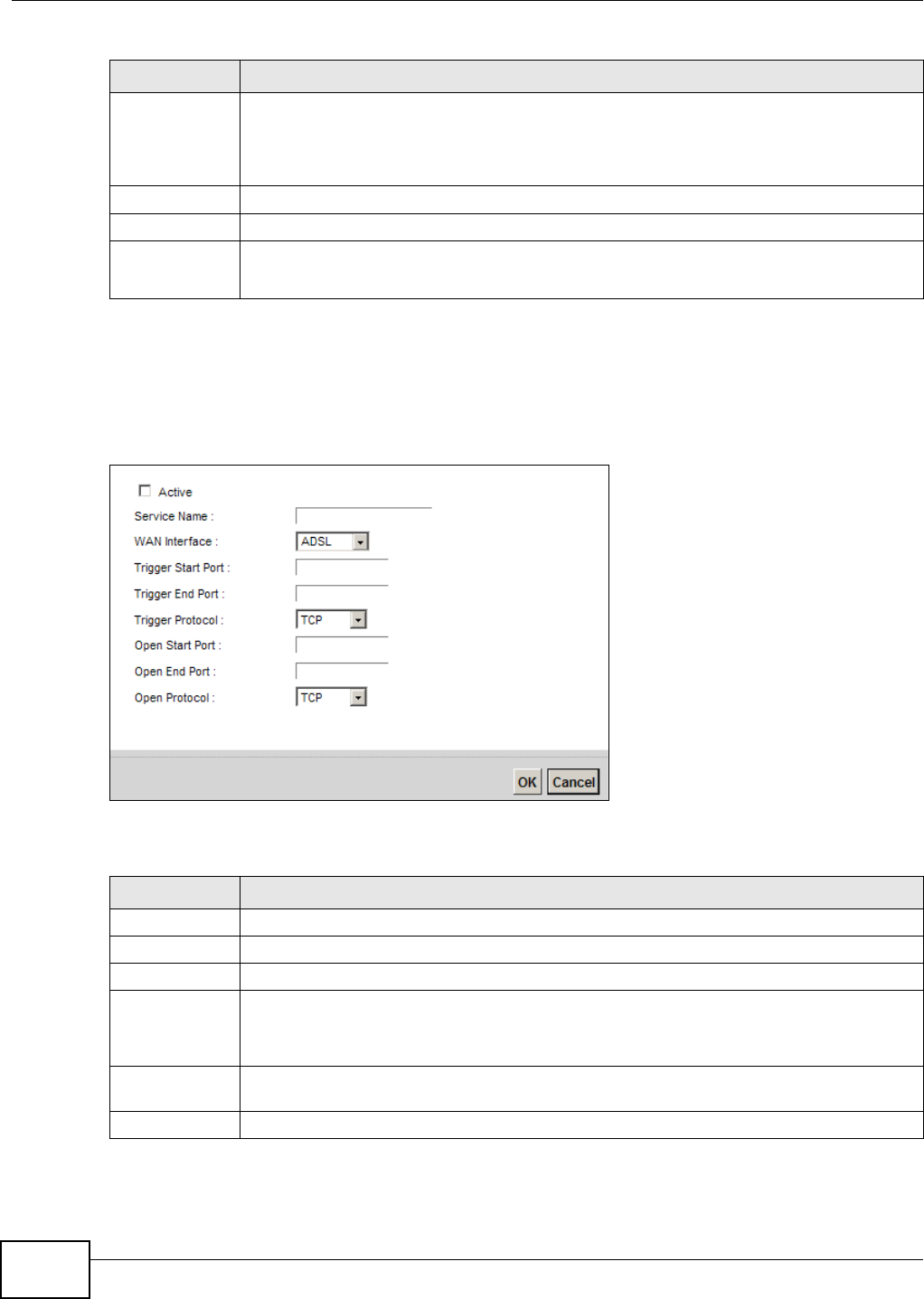
Chapter 10 Network Address Translation (NAT)
VMG8324-B10A / VMG8324-B30A Series User’s Guide
164
10.4.1 Add/Edit Port Triggering Rule
This screen lets you creat e new por t t riggering rules. Click Add new rule in t he Por t Triggering
screen or click a rule’s Ed it icon t o open t he following screen.
Figure 89 Port Triggering: Add/ Edit
The following t able describes t he labels in this screen.
Open St art Port The open port is a port ( or a range of port s) t hat a server on the WAN uses when it sends
out a part icular ser vice. The Device forwards t he traffic w it h t his port ( or range of port s) to
the client com put er on t he LAN t hat request ed the service.
This is t he first port num ber t hat ident ifies a serv ice.
Open End Port This is t he last port num ber t hat ident ifies a service.
Open Proto. This is t he open t ranspor t layer prot ocol.
Modify Click t he Ed it icon t o edit this rule.
Click the D ele t e icon t o delete an existing rule.
Table 61 Net work Sett ing > NAT > Port Triggering ( cont inued)
LABEL DESCRIPTION
Table 62 Port Triggering: Configuration Add/ Edit
LABEL DESCRIPTION
Act ive Select the check box t o enable t his rule.
Service Nam e Enter a nam e t o identify this rule using keyboard characters ( A-Z, a-z, 1- 2 and so on).
WAN I nt erface Select a WAN int erface for which you want to configure port t riggering rules.
Trigger St art
Port
The t rigger port is a port ( or a range of port s) that causes ( or triggers) t he Device to record
t he I P address of the LAN com put er that sent the traffic t o a server on t he WAN.
Type a port num ber or t he st art ing port num ber in a range of port num bers.
Trigger End
Port
Type a port num ber or the ending port num ber in a range of port num bers.
Trigger Prot ocol Select t he transport layer protocol from TCP, UDP, or TCP/ UDP.
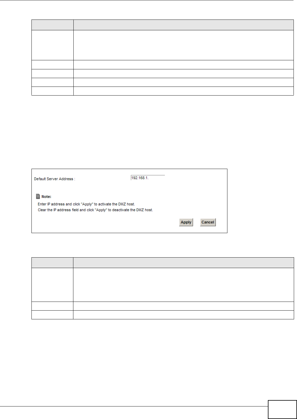
Chapter 10 Network Address Translation (NAT)
VMG8324-B10A / VMG8324-B30A Series User’s Guide 165
10.5 The DMZ Screen
I n addit ion to the servers for specified services, NAT support s a default server I P address. A default
server receives packet s from port s t hat are not specified in t he N AT Port For w ar ding Set u p
screen.
Figure 90 Net work Set t ing > NAT > DMZ
The following t able describes t he fields in t his screen.
Open St art Port The open port is a port ( or a range of port s) t hat a server on the WAN uses when it sends
out a part icular ser vice. The Device forwards t he traffic w it h t his port ( or range of port s) to
the client com put er on t he LAN t hat request ed the service.
Type a port num ber or t he st art ing port num ber in a range of port num bers.
Open End Port Type a port num ber or the ending port num ber in a range of port num bers.
Open Protocol Select the transport layer prot ocol from TCP, UDP, or TCP/ UDP.
OK Click OK to save your changes.
Cancel Click Ca nce l t o exit t his screen w it hout saving.
Table 62 Port Triggering: Configuration Add/ Edit ( cont inued)
LABEL DESCRIPTION
Table 63 Net work Sett ing > NAT > DMZ
LABEL DESCRIPTION
Default Server
Address
Ent er t he I P address of the default server which receives packet s from port s that are not
specified in t he N AT Port For w ardin g screen.
Note: If you do not assign a Default Server Address, the Device discards all packets
received for ports that are not specified in the NAT Port Forwarding screen.
Apply Click Apply t o save your changes.
Cancel Click Ca n cel t o rest ore your pr eviously saved set t ings.
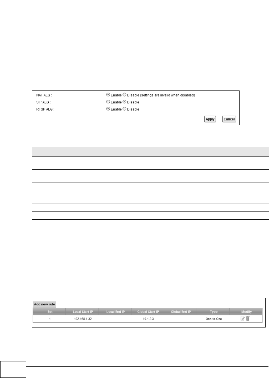
Chapter 10 Network Address Translation (NAT)
VMG8324-B10A / VMG8324-B30A Series User’s Guide
166
10.6 The ALG Screen
Som e NAT router s m ay include a SI P Applicat ion Layer Gat eway ( ALG). A SI P ALG allow s SI P calls
to pass t hrough NAT by exam ining and translat ing I P addresses em bedded in t he data st ream .
When t he Device regist ers wit h t he SI P register server, t he SI P ALG t ranslates t he Device’s privat e
I P address inside t he SI P data st r eam t o a public I P address. You do not need to use STUN or an
out bound proxy if your Device is behind a SI P ALG.
Use t his screen to enable and disable t he NAT and SI P (VoI P) ALG in t he Device. To access t his
screen, click N et w ork Set t ing > N AT > ALG.
Figure 91 Net work Set t ing > NAT > ALG
The following t able describes t he fields in this screen.
10.7 The Address Mapping Screen
Ordering your rules is im port ant because t he Device applies t he rules in t he order t hat you specify.
When a rule m atches the current packet , the Device t akes t he corresponding act ion and the
rem aining rules are ignored.
Click N et w ork Sett ing > N AT > Addr ess M a pping t o display t he following screen.
Figure 92 Net work Set t ing > NAT > Address Mapping
Table 64 Net work Sett ing > NAT > ALG
LABEL DESCRIPTION
NAT ALG Enable t his t o m ake sure applicat ions such as FTP and file t ransfer in I M applicat ions work
correct ly wit h port- for warding and address- m apping rules.
SI P ALG Enable this to m ake sure SI P ( VoI P) works correct ly wit h port- forwarding and address-
m apping rules.
RTSP ALG Enable t his t o have t he Device det ect RTSP t raffic and help build RTSP sessions t hrough its
NAT. The Real Tim e Stream ing ( m edia cont rol) Prot ocol (RTSP) is a rem ote cont rol for
m ult im edia on t he I nt ernet .
Apply Click Ap ply t o save your changes.
Cancel Click Cance l t o rest or e your previously saved settings.
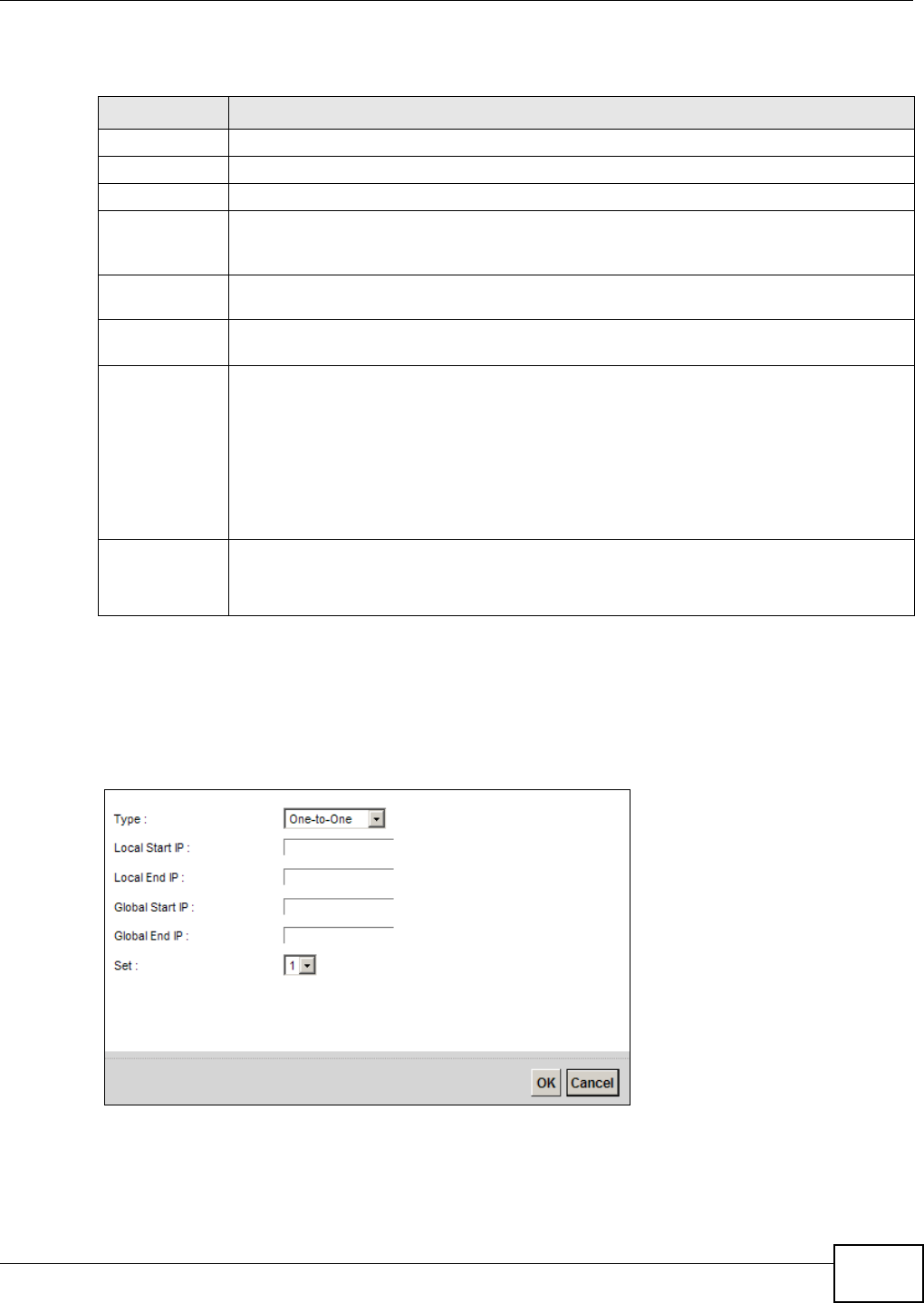
Chapter 10 Network Address Translation (NAT)
VMG8324-B10A / VMG8324-B30A Series User’s Guide 167
The following t able describes t he fields in this screen.
10.7.1 Add/Edit Address Mapping Rule
To add or edit an addr ess m apping rule, click Add new rule or the rule’s edit icon in the Addre ss
Ma ppin g screen t o display t he screen shown next.
Figure 93 Address Mapping: Add/ Edit
Table 65 Net wor k Sett ing > NAT > Address Mapping
LABEL DESCRIPTION
Add new rule Click this t o creat e a new rule.
Set This is the index num ber of t he address m apping set .
Local Start I P This is t he st art ing I nside Local I P Address ( I LA) .
Local End I P This is t he ending I nside Local I P Address ( I LA) . I f t he rule is for all local I P addr esses, t hen
this field displays 0.0.0.0 as t he Local Start I P address and 255.255.255.255 as t he Local
End I P addr ess. This field is blank for On e - t o - On e m apping t ypes.
Global St art I P This is t he st arting I nside Global I P Addr ess ( I GA) . Ent er 0.0.0.0 her e if you have a dynam ic
I P addr ess from your I SP. You can only do this for the M an y- t o- On e m apping type.
Global End I P This is the ending I nside Global I P Address ( I GA) . This field is blank for On e - t o- One and
Many- t o- One m apping t ypes.
Type This is t he address m apping type.
One - to- On e: This m ode m aps one local I P address to one global I P address. Note t hat port
num bers do not change for t he One- t o-one NAT m apping t ype.
M a ny - t o- O ne : This m ode m aps m ultiple local I P addresses t o one global I P addr ess. This is
equivalent t o SUA (i.e., PAT, port address t ranslat ion) , t he Device's Single User Account
feat ure t hat prev ious routers support ed only.
M a ny - t o- M a n y: This m ode m aps m ult iple local I P addresses t o shared global I P addresses.
Modify Click t he Edit icon t o go to t he screen w here you can edit t he address m apping rule.
Click the D ele t e icon to delet e an exist ing address m apping rule. Note that subsequent
addr ess m apping rules m ove up by one w hen you t ake t his act ion.
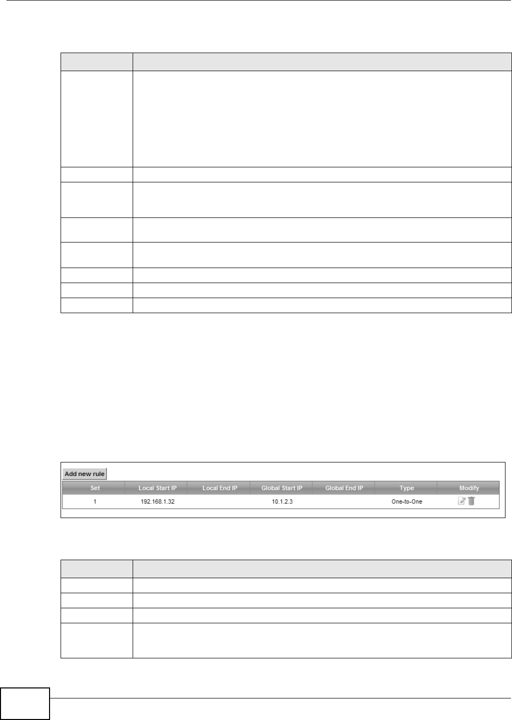
Chapter 10 Network Address Translation (NAT)
VMG8324-B10A / VMG8324-B30A Series User’s Guide
168
The following t able describes t he fields in this screen.
10.8 The Address Mapping Screen
Ordering your rules is im port ant because t he Device applies t he rules in t he order t hat you specify.
When a rule m atches the current packet , the Device t akes t he corresponding act ion and the
rem aining rules are ignored.
Click N et w ork Sett ing > N AT > Addr ess M a pping t o display t he following screen.
Figure 94 Net work Set t ing > NAT > Address Mapping
The following t able describes t he fields in this screen.
Table 66 Address Mapping: Add/ Edit
LABEL DESCRIPTION
Type Choose t he I P/ port m apping type from one of t he following.
One - to- On e: This m ode m aps one local I P address to one global I P address. Note t hat port
num bers do not change for t he One- t o-one NAT m apping t ype.
M a ny - t o- O ne : This m ode m aps m ultiple local I P addresses t o one global I P addr ess. This is
equivalent t o SUA (i.e., PAT, port address t ranslat ion) , t he Device's Single User Account
feat ure t hat prev ious routers support ed only.
M a ny - t o- M a n y: This m ode m aps m ult iple local I P addresses t o shared global I P addresses.
Local Start I P Enter t he st arting I nside Local I P Addr ess (I LA) .
Local End I P Enter the ending I nside Local I P Address (I LA) . I f the rule is for all local I P addresses, t hen
this field displays 0.0.0.0 as t he Local Start I P address and 255.255.255.255 as t he Local
End I P addr ess. This field is blank for On e - t o - On e m apping t ypes.
Global St art I P Enter t he st ar ting I nside Global I P Address ( I GA) . Ent er 0.0.0.0 here if you have a dynam ic
I P addr ess from your I SP. You can only do this for the M an y- t o- On e m apping type.
Global End I P Ent er the ending I nside Global I P Address ( I GA) . This field is blank for One - t o- On e and
Many- t o- One m apping t ypes.
Set Select the num ber of the m apping set for which you want t o configur e.
OK Click OK t o save your changes.
Cancel Click Ca ncel t o exit t his screen wit hout saving.
Table 67 Net wor k Sett ing > NAT > Address Mapping
LABEL DESCRIPTION
Add new rule Click this t o creat e a new rule.
Set This is the index num ber of t he address m apping set .
Local Start I P This is t he st art ing I nside Local I P Address ( I LA) .
Local End I P This is t he ending I nside Local I P Address ( I LA) . I f t he rule is for all local I P addr esses, t hen
this field displays 0.0.0.0 as t he Local Start I P address and 255.255.255.255 as t he Local
End I P addr ess. This field is blank for On e - t o - On e m apping t ypes.
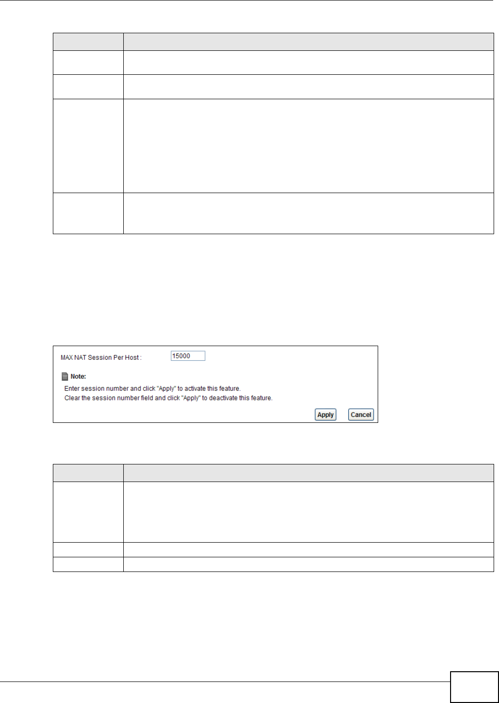
Chapter 10 Network Address Translation (NAT)
VMG8324-B10A / VMG8324-B30A Series User’s Guide 169
10.9 The Sessions Screen
Use t his screen to lim it t he num ber of concurrent NAT sessions a client can use. Click N e t w ork
Set t ing > N AT > Session s to display t he following screen.
Figure 95 Net work Set t ing > NAT > Sessions
The following t able describes t he fields in this screen.
10.10 Technical Reference
This part cont ains m ore inform at ion regarding NAT.
Global St art I P This is t he st arting I nside Global I P Addr ess ( I GA) . Ent er 0.0.0.0 her e if you have a dynam ic
I P addr ess from your I SP. You can only do this for the M an y- t o- On e m apping type.
Global End I P This is the ending I nside Global I P Address ( I GA) . This field is blank for On e - t o- One and
Many- t o- One m apping t ypes.
Type This is t he address m apping type.
One - to- On e: This m ode m aps one local I P address to one global I P address. Note t hat port
num bers do not change for t he One- t o-one NAT m apping t ype.
M a ny - t o- O ne : This m ode m aps m ultiple local I P addresses t o one global I P addr ess. This is
equivalent t o SUA (i.e., PAT, port address t ranslat ion) , t he Device's Single User Account
feat ure t hat prev ious routers support ed only.
M a ny - t o- M a n y: This m ode m aps m ult iple local I P addresses t o shared global I P addresses.
Modify Click t he Edit icon t o go to t he screen w here you can edit t he address m apping rule.
Click the D ele t e icon to delet e an exist ing address m apping rule. Note that subsequent
addr ess m apping rules m ove up by one w hen you t ake t his act ion.
Table 67 Net work Sett ing > NAT > Address Mapping ( continued)
LABEL DESCRIPTION
Table 68 Net work Sett ing > NAT > Sessions
LABEL DESCRIPTION
WAX NAT
Session Per
Host
Use t his field t o set a lim it to the num ber of concurrent NAT sessions each client host can
have.
I f only a few clients use peer t o peer applicat ions, you can raise t his num ber t o im prove
their perform ance. Wit h heavy peer- t o- peer applicat ion use, lower t his num ber t o ensure no
single client uses t oo m any of t he available NAT sessions.
Apply Click this t o save your changes on t his screen.
Cancel Click t his to exit t his screen w it hout saving any changes.

Chapter 10 Network Address Translation (NAT)
VMG8324-B10A / VMG8324-B30A Series User’s Guide
170
10.10.1 NAT Definitions
I nside/ outside denot es where a host is locat ed relat ive t o t he Device, for exam ple, t he com put ers
of your subscribers are the inside host s, while t he web servers on t he I nt ernet are t he out side
host s.
Global/ local denot es t he I P address of a host in a packet as t he packet t raverses a rout er, for
exam ple, t he local address refers t o the I P address of a host when the packet is in t he local
net work, while t he global address refers to the I P address of t he host when t he sam e packet is
traveling in t he WAN side.

Chapter 10 Network Address Translation (NAT)
VMG8324-B10A / VMG8324-B30A Series User’s Guide 171
Not e that inside/ out side refers t o the location of a host , while global/ local refers t o t he I P address
of a host used in a packet . Thus, an inside local address ( I LA) is t he I P address of an inside host in
a packet when t he packet is still in t he local net work, while an inside global address ( I GA) is the I P
address of t he sam e inside host w hen t he packet is on t he WAN side. The following table
sum m arizes t his inform at ion.
NAT never changes the I P addr ess ( eit her local or global) of an out side host .
10.10.2 What NAT Does
I n t he sim plest form , NAT changes t he source I P address in a packet received from a subscriber
( t he inside local addr ess) t o another ( t he inside global address) before forwarding t he packet t o t he
WAN side. When the response com es back, NAT translates t he dest inat ion addr ess ( t he inside
global address) back t o t he inside local addr ess before forwarding it t o t he original inside host . Note
that t he I P address ( eit her local or global) of an outside host is never changed.
The global I P addresses for the inside hosts can be eit her stat ic or dynam ically assigned by t he I SP.
I n addit ion, you can designate servers, for exam ple, a web ser ver and a telnet server, on your local
net work and m ake t hem accessible t o t he out side world. I f you do not define any server s ( for Many-
to-One and Many- t o- Many Overload m apping), NAT offers t he additional benefit of firewall
protect ion. Wit h no servers defined, your Device filt ers out all incom ing inquiries, thus preventing
int ruders from probing your net work. For m ore inform ation on I P address t ranslation, refer t o RFC
1631, The I P Net work Address Translat or ( NAT) .
Table 69 NAT Definitions
ITEM DESCRIPTION
I nside This refers t o t he host on t he LAN.
Outside This refers t o the host on t he WAN.
Local This refers t o the packet address ( source or dest ination) as t he packet travels on t he
LAN.
Global This refers t o t he packet address (source or destinat ion) as t he packet travels on t he
WAN.
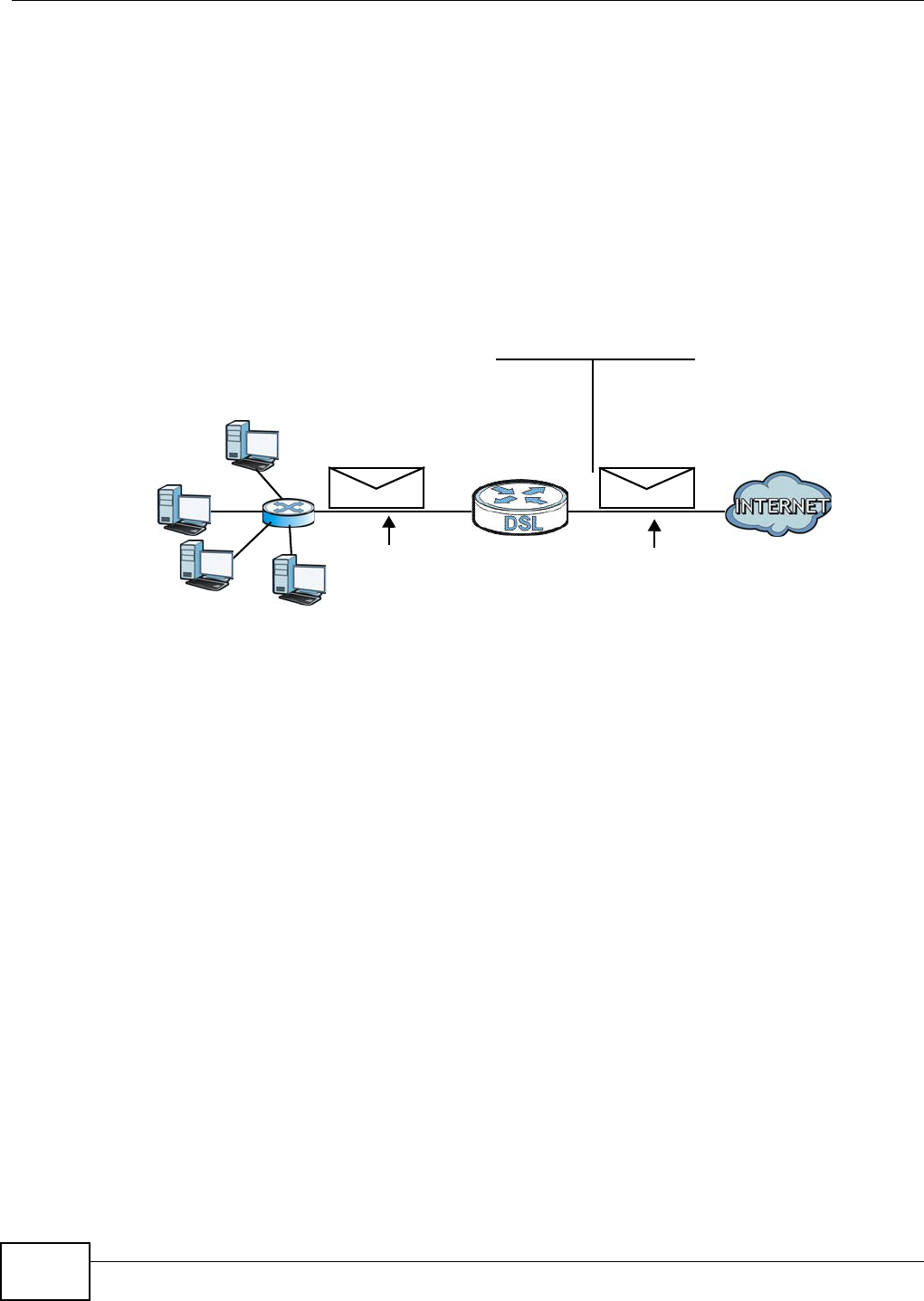
Chapter 10 Network Address Translation (NAT)
VMG8324-B10A / VMG8324-B30A Series User’s Guide
172
10.10.3 How NAT Works
Each packet has t wo addresses – a source address and a dest inat ion address. For out going packet s,
the I LA (I nside Local Address) is t he source address on t he LAN, and the I GA (I nside Global
Address) is t he source address on the WAN. For incom ing packet s, t he I LA is t he dest inat ion
address on t he LAN, and t he I GA is t he dest inat ion address on t he WAN. NAT m aps privat e ( local)
I P addresses to globally unique ones requir ed for com m unication wit h host s on ot her net works. I t
replaces t he original I P source address (and TCP or UDP sour ce port num bers for Many- t o- One and
Many- t o- Many Overload NAT m apping) in each packet and then forwards it t o the I nternet . The
Device keeps t rack of the original addr esses and port num bers so incom ing reply packets can have
their original values restor ed. The following figure illust rates t his.
Figure 96 How NAT Works
192.168.1.13
192.168.1.10
192.168.1.11
192.168.1.12 SA
192.168.1.10
SA
IGA1
Inside Local
IP Address
192.168.1.10
192.168.1.11
192.168.1.12
192.168.1.13
Inside Global
IP Address
IGA 1
IGA 2
IGA 3
IGA 4
NAT Table
WAN
LAN
Inside Local
Address (ILA)
Inside Global
Address (IGA)
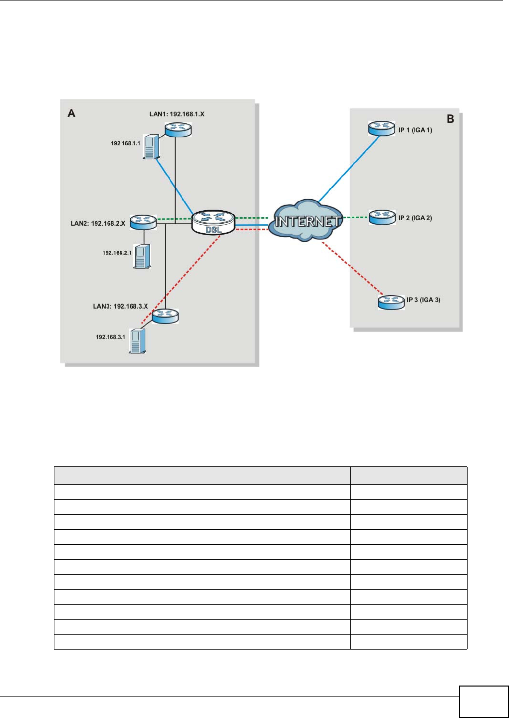
Chapter 10 Network Address Translation (NAT)
VMG8324-B10A / VMG8324-B30A Series User’s Guide 173
10.10.4 NAT Application
The following figure illust rat es a possible NAT application, where t hree inside LANs ( logical LANs
using I P alias) behind the Device can com m unicat e with t hree dist inct WAN net works.
Figure 97 NAT Applicat ion Wit h I P Alias
Port Forwarding: Services and Port Numbers
The m ost often used port num bers are shown in the following t able. Please refer t o RFC 1700 for
further inform ation about port num bers. Please also refer t o t he Support ing CD for m ore exam ples
and det ails on port forwarding and NAT.
Table 70 Services and Port Num bers
SERVICES PORT NUMBER
ECHO 7
FTP (File Transfer Prot ocol) 21
SMTP ( Sim ple Mail Transfer Protocol) 25
DNS ( Dom ain Nam e Syst em ) 53
Finger 79
HTTP ( Hyper Text Transfer prot ocol or WWW, Web) 80
POP3 (Post Office Pr ot ocol) 110
NNTP (Net work New s Transport Prot ocol) 119
SNMP (Sim ple Networ k Managem ent Prot ocol) 161
SNMP trap 162
PPTP ( Point- t o- Point Tunneling Protocol) 1723
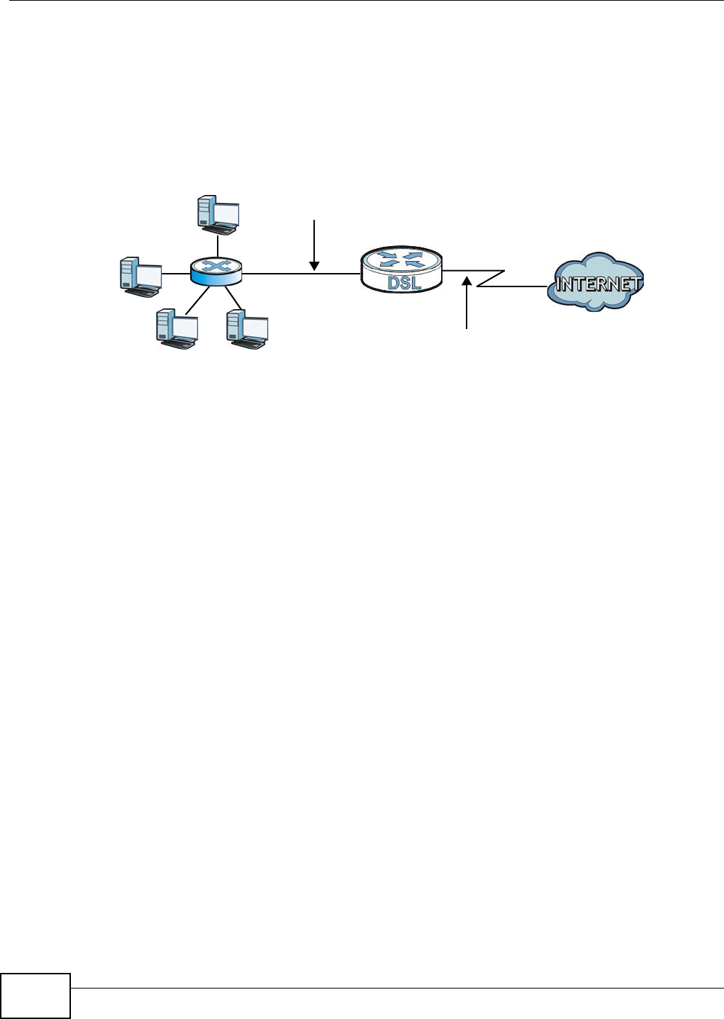
Chapter 10 Network Address Translation (NAT)
VMG8324-B10A / VMG8324-B30A Series User’s Guide
174
Port Forwarding Example
Let 's say you want to assign port s 21- 25 to one FTP, Telnet and SMTP server (A in t he exam ple) ,
port 80 t o anot her ( B in the exam ple) and assign a default server I P address of 192.168.1.35 t o a
third (C in t he exam ple) . You assign the LAN I P addresses and t he I SP assigns the WAN I P address.
The NAT network appears as a single host on t he I nt ernet .
Figure 98 Mult iple Servers Behind NAT Exam ple
D=192.168.1.36
192.168.1.1
IP address assigned by ISP
A=192.168.1.33
B=192.168.1.34
C=192.168.1.35

VMG8324-B10A / VMG8324-B30A Series User’s Guide 175
CHAPTER 11
Dynamic DNS Setup
11.1 Overview
DNS
DNS (Dom ain Nam e Syst em ) is for m apping a dom ain nam e to it s corresponding I P address and
vice versa. The DNS server is ext rem ely im port ant because wit hout it , you m ust know the I P
address of a m achine before you can access it .
I n addit ion to the syst em DNS server( s), each WAN int erface (service) is set to have it s own st atic
or dynam ic DNS server list . You can configure a DNS st atic route to forward DNS queries for cert ain
dom ain nam es through a specific WAN int erface to it s DNS server( s) . The Device uses a system
DNS server ( in t he order you specify in t he Broa dband screen) t o resolve dom ain nam es t hat do
not m atch any DNS rout ing entry. Aft er t he Device receives a DNS reply from a DNS server, it
creates a new ent ry for t he resolved I P address in the rout ing t able.
Dynamic DNS
Dynam ic DNS allows you t o update your current dynam ic I P address w ith one or m any dynam ic
DNS services so that anyone can cont act you ( in Net Meet ing, CU-SeeMe, etc.) . You can also access
your FTP server or Web site on your own com put er using a dom ain nam e ( for inst ance
m yhost .dhs.org, where m yhost is a nam e of your choice) t hat will never change inst ead of using an
I P address t hat changes each t im e you reconnect . Your friends or relat ives will always be able t o
call you even if they don't know your I P address.
First of all, you need t o have regist ered a dynam ic DNS account with www.dyndns.org. This is for
people wit h a dynam ic I P from t heir I SP or DHCP server t hat would still like t o have a dom ain nam e.
The Dynam ic DNS service provider will give you a password or key.
11.1.1 What You Can Do in this Chapter
• Use the D N S Entr y screen to view, configure, or rem ove DNS routes (Sect ion 11.2 on page
176) .
• Use the D yna m ic DN S screen t o enable DDNS and configure t he DDNS sett ings on t he Device
(Sect ion 11.3 on page 177) .
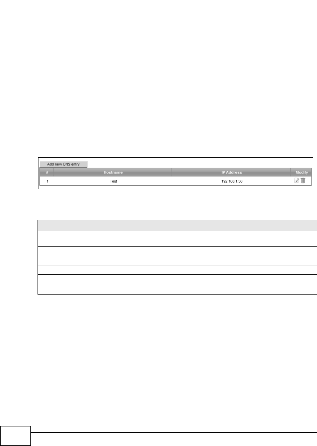
Chapter 11 Dynamic DNS Setup
VMG8324-B10A / VMG8324-B30A Series User’s Guide
176
11.1.2 What You Need To Know
DYNDNS Wildcard
Enabling the w ildcard feature for your host causes * .yourhost .dyndns.org t o be aliased to the sam e
I P address as yourhost .dyndns.org. This feature is useful if you want t o be able t o use, for exam ple,
ww w.yourhost .dyndns.or g and st ill reach your host nam e.
I f you have a privat e WAN I P address, t hen you cannot use Dynam ic DNS.
11.2 The DNS Entry Screen
Use t his scr een t o view and configure DNS rout es on t he Device. Click N e t w or k Se t t ing > D N S to
open the D N S En t ry screen.
Figure 99 Net work Set t ing > DNS > DNS Ent ry
The following t able describes t he fields in t his screen.
Table 71 Net work Sett ing > DNS > DNS Ent ry
LABEL DESCRIPTION
Add new DNS
entry
Click t his to creat e a new DNS entry.
#This is the index num ber of t he entry.
Host nam e This indicates t he host nam e or dom ain nam e.
I P Address This indicat es t he I P address assigned t o t his com put er.
Modify Click t he Ed it icon t o edit t he rule.
Click the D e le t e icon t o delet e an ex ist ing rule.
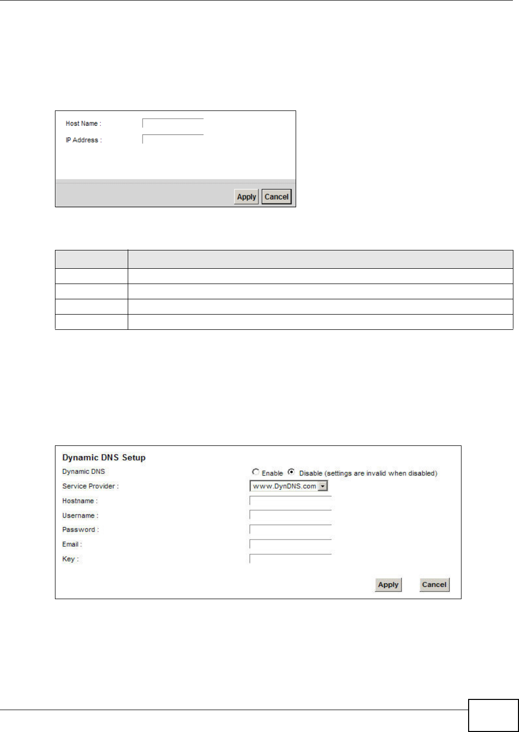
Chapter 11 Dynamic DNS Setup
VMG8324-B10A / VMG8324-B30A Series User’s Guide 177
11.2.1 Add/Edit DNS Entry
You can m anually add or edit t he Device’s DNS nam e and I P address ent ry. Click Add ne w D N S
e nt r y in t he DN S Ent r y screen or the Ed it icon next to the ent ry you want t o edit . The screen
shown next appears.
Figure 100 DNS Ent ry : Add/ Edit
The following t able describes t he labels in this screen.
11.3 The Dynamic DNS Screen
Use t his scr een t o change your Device’s DDNS. Click N e t w or k Set t ing > D N S > Dyn a m ic DN S.
The screen appears as shown.
Figure 101 Network Sett ing > DNS > Dynam ic DNS
Table 72 DNS Ent ry: Add/ Edit
LABEL DESCRIPTION
Host Nam e Enter t he host nam e of t he DNS ent ry.
I P Address Enter t he I P address of t he DNS entry.
Apply Click Apply t o save your changes.
Cancel Click Ca nce l to exit this screen without saving.

Chapter 11 Dynamic DNS Setup
VMG8324-B10A / VMG8324-B30A Series User’s Guide
178
The following t able describes t he fields in t his screen.
Table 73 Net work Set t ing > DNS > > Dynam ic DNS
LABEL DESCRIPTION
Dynam ic DNS Select Enable t o use dynam ic DNS.
Service
Provider
Select your Dynam ic DNS service provider from the dr op- down list box.
Host nam e Ty pe the dom ain nam e assigned t o your Dev ice by your Dynam ic DNS provider.
You can specify up to t wo host nam es in the field separated by a com m a ( "," ) .
User nam e Ty pe your user nam e.
Passw ord Type t he password assigned t o you.
Em ail I f you select TZO in t he Se r vice Provide r field, ent er t he user nam e you used to register
for t his service.
Key I f you select TZO in the Se rvice Pr ovide r field, ent er the password you used t o regist er for
this serv ice.
Apply Click Apply t o save your changes.
Cancel Click Ca nce l to ex it t his scr een wit hout sav ing.

VMG8324-B10A / VMG8324-B30A Series User’s Guide 179
CHAPTER 12
Interface Group
12.1 Overview
By default , all LAN and WAN interfaces on the Device are in the sam e group and can com m unicat e
wit h each other. Creat e int erface groups to have t he Device assign t he I P addresses in different
dom ains t o different groups. Each group act s as an independent net work on the Device. This lets
devices connect ed to an int erface group’s LAN int erfaces com m unicate t hrough the int erface
group’s WAN or LAN interfaces but not other WAN or LAN int erfaces.
12.1.1 What You Can Do in this Chapter
The I nt e rface Group screens let you cr eate m ultiple networks on t he Device (Sect ion 12.2 on
page 179) .
12.2 The Interface Group Screen
You can m anually add a LAN interface t o a new group. Alternatively, you can have t he Device
aut om atically add t he incom ing t raffic and t he LAN int erface on which t raffic is received to an
int erface group when it s DHCP Vendor I D option inform at ion m at ches one listed for the int erface
group.
Use t he LAN screen t o configure t he private I P addresses t he DHCP server on t he Device assigns to
the clients in the default and/ or user- defined groups. I f you set t he Device t o assign I P addresses
based on the client ’s DHCP Vendor I D opt ion inform ation, you m ust enable DHCP server and
configure LAN TCP/ I P set tings for bot h t he default and user- defined groups. See Chapter 7 on page
107 for m ore inform at ion.
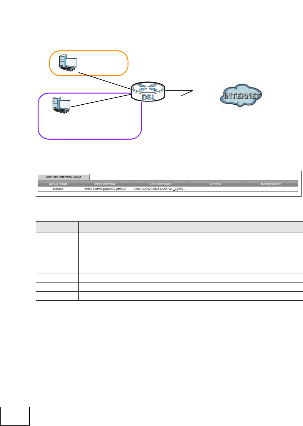
Chapter 12 Interface Group
VMG8324-B10A / VMG8324-B30A Series User’s Guide
180
I n t he follow ing exam ple, t he client t hat sends packet s wit h t he DHCP Vendor I D opt ion set t o MSFT
5.0 ( m eaning it is a Windows 2000 DHCP client ) is assigned the I P address 192.168.2.2 and uses
the WAN VDSL_PoE/ ppp0.1 interface.
Figure 102 I nt erface Grouping Applicat ion
Click N et w or k Se t t in g > I nt e r f a ce Grou p t o open the following scr een.
Figure 103 Network Sett ing > I nt erface Group
The following t able describes t he fields in t his screen.
12.2.1 Interface Group Configuration
Click t he Add N e w I nt e r fa ce Group butt on in the I nt erface Grou p screen t o open t he following
screen. Use t his screen t o creat e a new interface group.
Table 74 Net work Sett ing > I nt erface Group
LABEL DESCRIPTION
Add New
I nterface Group
Click t his button t o creat e a new int erface group.
Group Nam e This shows t he descriptive nam e of t he group.
WAN I nt erface This show s t he WAN interfaces in the gr oup.
LAN I nterfaces This shows t he LAN int erfaces in t he group.
Criteria This shows t he filter ing criteria for t he group.
Modify Click the De le t e icon t o rem ove the group.
Add Click t his button t o create a new group.
Default: ETH 2~4
Internet
192.168.1.x/24
192.168.2.x/24
VDSL_PoE/ppp0.1
eth10.0
DHCP Vendor ID option: MSFT 5.0
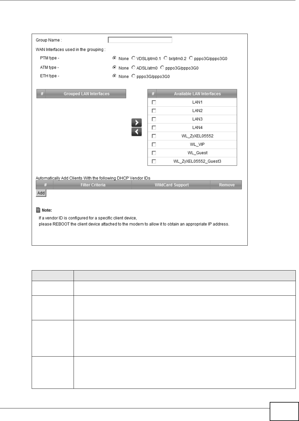
Chapter 12 Interface Group
VMG8324-B10A / VMG8324-B30A Series User’s Guide 181
Note: An int erface can belong t o only one group at a t im e.
Figure 104 I nt erface Group Configurat ion
The following t able describes t he fields in t his screen.
Table 75 I nt erface Group Configurat ion
LABEL DESCRIPTION
Group Nam e Ent er a nam e t o ident ify t his group. You can enter up to 30 charact er s. You can use let t ers,
num bers, hyphens ( - ) and underscores ( _) . Spaces are not allowed.
WAN I nt erface
used in the
grouping
Select t he WAN interface this group uses. The group can have up to one PTM int erface, up
to one ATM interface and up t o one ETH interface.
Select N one t o not add a WAN int erface t o this group.
Grouped LAN
I nterfaces
Available LAN
I nterfaces
Select one or m ore LAN interfaces ( Et hernet LAN, HPNA or wireless LAN) in t he Av a ila ble
LAN I nt erface s list and use t he left arrow t o m ove t hem t o t he Grou pe d LAN I n t e rfa ces
list t o add the interfaces to this group.
To rem ove a LAN or wireless LAN int erface from t he Gr ou pe d LAN I nt e r fa ce s, use the
right- facing arrow.
Aut om at ically
Add Clients
With the
following DHCP
Ven dor I Ds
Click Add t o identify LAN host s t o add t o the int er face group by crit eria such as t he type of
the hardware or firm ware. See Sect ion 12.2.2 on page 182 for m ore infor m ation.
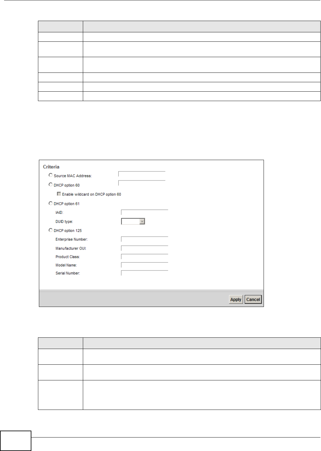
Chapter 12 Interface Group
VMG8324-B10A / VMG8324-B30A Series User’s Guide
182
12.2.2 Interface Grouping Criteria
Click t he Add butt on in t he I nt e r fa ce Gr ouping Con figu r a t ion screen t o open the following
screen.
Figure 105 I nt erface Grouping Crit eria
The following t able describes t he fields in t his screen.
#This shows t he index num ber of t he rule.
Filt er Criteria This shows t he filter ing crit eria. The LAN int erface on which the m at ched t raffic is received
will belong t o t his group aut om at ically.
WildCard
Support
This shows if wildcard on DHCP opt ion 60 is enabled.
Rem ov e Click t he Rem ove icon to delet e t his rule fr om t he Device.
Apply Click Apply t o save your changes back to t he Device.
Cancel Click Ca nce l to exit t his screen w it hout saving.
Table 75 I nt erface Group Configurat ion ( cont inued)
LABEL DESCRIPTION
Table 76 I nt erface Grouping Crit eria
LABEL DESCRIPTION
Source MAC
Address
Enter the source MAC address of the packet.
DHCP Opt ion
60
Select this opt ion and ent er the Vendor Class I dentifier ( Option 60) of t he m atched t raffic,
such as the t ype of t he har dware or firm war e.
Enable
wildcard on
DHCP
opt ion 60
opt ion
Select this opt ion to be able to use w ildcards in t he Vendor Class I dent ifier configur ed for
DHCP option 60.

Chapter 12 Interface Group
VMG8324-B10A / VMG8324-B30A Series User’s Guide 183
DHCP Opt ion
61
Select this and enter t he device ident ity of the m at ched t raffic.
I AI D Enter t he I dent it y Associat ion I dentifier (I AI D) of t he device, for exam ple, t he WAN
connection index num ber.
DUI D type Select D UI D - LLT ( DUI D Based on Link- layer Address Plus Tim e) t o enter t he hardware
type, a t im e value and the MAC address of the device.
Select D UI D - EN ( DUI D Assigned by Vendor Based upon Ent erprise Num ber) t o ent er the
vendor’s registered enterprise num ber.
Select DUI D- LL ( DUI D Based on Link- layer Address) to enter t he device’s hardware t ype
and hardware address ( MAC address) in the follow ing fields.
Select Ot h er t o enter any st ring that ident ifies the device in t he DUI D field.
DHCP Opt ion
125
Select this and ent er vendor specific inform at ion of the m atched traffic.
Ent erprise
Nu m ber
Ent er t he vendor ’s 32- bit enterprise num ber regist ered w it h the I ANA ( I nt ernet Assigned
Num bers Aut hor it y) .
Man uf act ur
er OUI
Specify the vendor ’s OUI ( Or ganization Unique I dent ifier) . I t is usually t he first t hree byt es
of the MAC address.
Product
Class
Enter t he product class of the device.
Model
Nam e
Enter the m odel nam e of t he dev ice.
Serial
Nu m ber
Ent er t he serial num ber of t he device.
Apply Click Apply t o save your changes back to t he Device.
Cancel Click Ca nce l to exit t his screen w it hout saving.
Table 76 I nt erface Grouping Crit eria ( continued)
LABEL DESCRIPTION

Chapter 12 Interface Group
VMG8324-B10A / VMG8324-B30A Series User’s Guide
184
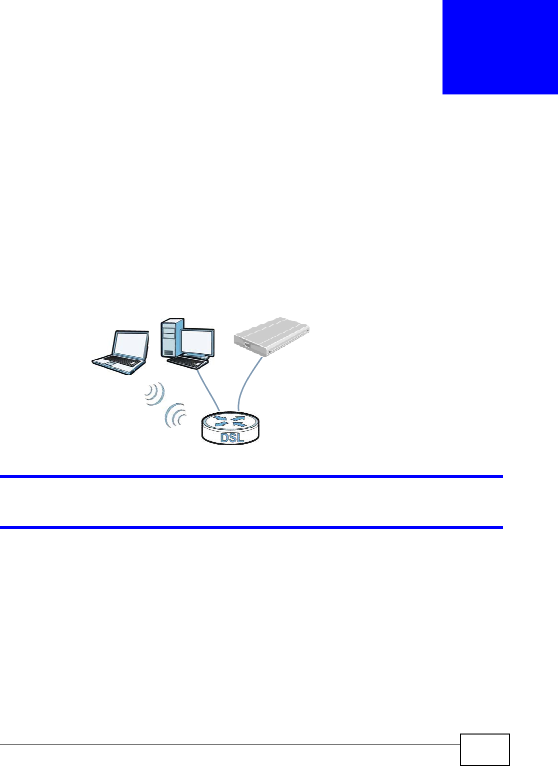
VMG8324-B10A / VMG8324-B30A Series User’s Guide 185
CHAPTER 13
USB Service
13.1 Overview
You can share files on a USB m em ory st ick or hard drive connected t o your Device wit h users on
your net work.
The following figure is an overview of t he Device’s file server feat ure. Com put ers A and B can
access files on a USB device ( C) which is connect ed to the Device.
Figure 106 File Sharing Overview
The Device will not be able t o j oin the workgroup if your local area network has restrict ions
set up t hat do not allow devices t o j oin a workgroup. I n this case, cont act your net work
adm inistrat or.
13.1.1 What You Can Do in this Chapter
• Use the File Sh a ring screen t o enable file-sharing server (Sect ion 13.1.3 on page 187) .
• Use the M edia Se r ve r screen to enable or disable t he sharing of m edia files ( Sect ion 13.3 on
page 190) .
• Use the Pr int er Se rver scr een t o enable t he print server (Sect ion 13.4 on page 191) .
13.1.2 What You Need To Know
The following t erm s and concept s m ay help as you read t his chapt er.
A
BC

Chapter 13 USB Service
VMG8324-B10A / VMG8324-B30A Series User’s Guide
186
13.1.2.1 About File Sharing
Workgroup name
This is the nam e given to a set of com put ers t hat are connected on a net w ork and share resources
such as a print er or files. Window s aut om at ically assigns t he workgroup nam e when you set up a
net work.
Shares
When sett ings are set t o default , each USB device connect ed to the Device is given a folder, called
a “ share”. I f a USB hard drive connect ed to t he Device has m ore than one part it ion, then each
partition will be allocat ed a share. You can also configure a “ share” t o be a sub-folder or file on t he
USB device.
File Systems
A file system is a way of st oring and organizing files on your hard drive and st orage device. Often
different operat ing syst em s such as Windows or Linux have different file syst em s. The file sharing
feat ure on your Device support s File Allocation Table ( FAT) and FAT32.
Common Internet File System
The Device uses Com m on I nt ernet File System ( CI FS) prot ocol for it s file sharing funct ions. CI FS
com pat ible com puters can access t he USB file st orage devices connect ed t o t he Device. CI FS
protocol is support ed on Microsoft Window s, Linux Sam ba and ot her operating syst em s ( r efer to
your system s specifications for CI FS com pat ibilit y) .
13.1.2.2 About Printer Server
Print Server
This is a com put er or other device which m anages one or m ore printers, and which sends print j obs
to each printer from t he com put er it self or ot her devices.
Operating System
An operat ing syst em ( OS) is t he int erface which helps you m anage a com put er. Com m on exam ples
are Microsoft Windows, Mac OS or Linux.
TCP/IP
TCP/ I P ( Transm ission Control Prot ocol/ I nt ernet Protocol) is a set of com m unicat ions protocols t hat
m ost of t he I nt ernet runs on.
Port
A port m aps a net work service such as htt p t o a process running on your com put er, such as a
process run by your web browser. When t raffic from t he I nt ernet is received on your com put er, t he
port num ber is used t o ident ify which process running on your com put er it is int ended for.

Chapter 13 USB Service
VMG8324-B10A / VMG8324-B30A Series User’s Guide 187
Supported OSs
Your operat ing syst em m ust support TCP/ I P port s for print ing and be com pat ible wit h t he RAW ( port
9100) protocol.
The following OSs support Device’s print er sharing feat ure.
• Microsoft Windows 95, Windows 98 SE ( Second Edit ion) , Windows Me, Windows NT 4.0, Windows
2000, Windows XP or Macintosh OS X.
13.1.3 Before You Begin
Make sure t he Device is connected t o your net w ork and t urned on.
1Connect t he USB device to one of t he Device’s USB port. Make sure t he Device is connected t o your
net work.
2The Device detects t he USB device and m akes its cont ent s available for browsing. I f you are
connect ing a USB hard drive that com es wit h an ext ernal power supply, m ake sur e it is connected
to an appropriat e power source t hat is on.
Not e: I f your USB device cannot be detect ed by t he Device, see t he t roubleshoot ing for
suggest ions.
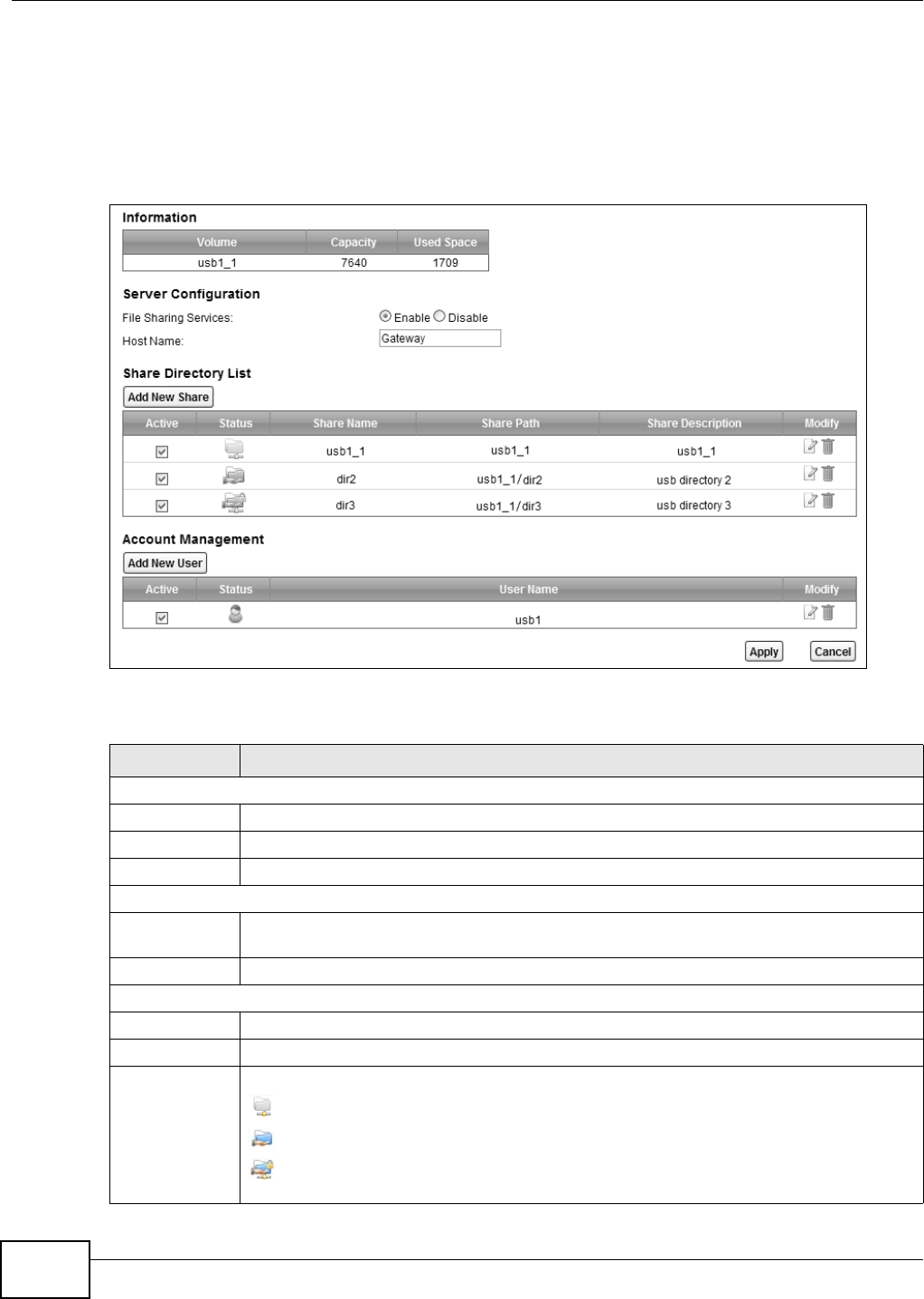
Chapter 13 USB Service
VMG8324-B10A / VMG8324-B30A Series User’s Guide
188
13.2 The File Sharing Screen
Use t his screen to set up file sharing through the Device. The Device’s LAN users can access the
shared folder ( or share) from t he USB device insert ed in t he Device. To access t his screen, click
N e t w ork Se t t ing > USB Service > File Sh a ring.
Figure 107 Network Sett ing > USB Service > File Sharing
Each field is described in the following t able.
Table 77 Net work Sett ing > Hom e Networking > File Sharing
LABEL DESCRIPTION
I nfor m at ion
Vo l u m e This is t he volum e nam e t he Device gives to an insert ed USB device.
Capacit y This is t he t otal available m em ory size ( in m egabytes) on t he USB device.
Used Space This is t he m em ory size ( in m egabyt es) already used on t he USB device.
Ser ver Configurat ion
File Sharing
Services
Select En a ble t o act ivate file sharing t hrough the Device.
Host Nam e Ent er the host nam e on t he shar e.
Share Direct ory List
Add New Shar e Click t his t o creat e a new share for users t o access thr ough the Device.
Act ive Select t his t o act ivat e t he share.
St atus This field shows the stat us of t he shar e.
: The share is not activat ed.
: The share is act ivat ed and shar ed to all users.
: The share is activat ed and only shared t o the specified users list ed in the Accou nt
M a na ge m e n t sect ion below.
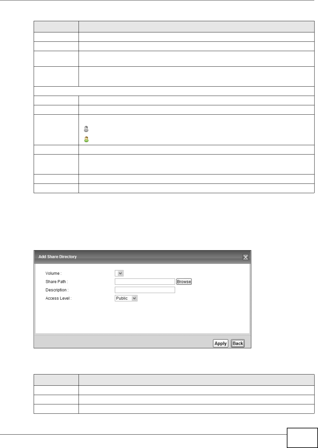
Chapter 13 USB Service
VMG8324-B10A / VMG8324-B30A Series User’s Guide 189
13.2.1 The Add New Share Screen
Use t his screen to create a share. To access this screen, click t he Add new share but t on in t he
N e t w ork Se t t ing > USB Service > File Sh a ring screen.
Figure 108 Network Sett ing > USB Service > File Sharing > Add new share
Each field is descr ibed in the following t able.
Share Nam e This field shows t he nam e of a folder that is shared t hrough t he Device.
Share Path This field show s t he locat ion of t he share in t he Device.
Share
Descript ion
This field shows a shor t descript ion of the shar e.
Modify Click t he Ed it icon to m odify t he share.
Click the D ele t e icon t o rem ove t he share from t he Device.
Account Managem ent
Add New User Click t his but t on to cr eat e a user account to access the secured shares.
Act ive Select t his t o allow t he user to access the secured shares.
St atus This field shows the stat us of t he user.
: The user account is not activat ed for the share.
: The user account is act ivat ed for the share.
User Nam e This is the nam e of a user who is allowed t o access the secured shares on t he USB device.
Modify Click t he Ed it icon to m odify t he user account .
Click the D ele t e icon t o rem ove t he user account fr om t he Device.
Apply Click this to save your changes t o t he Device.
Cancel Click this to restore your previously saved set t ings.
Table 77 Net work Sett ing > Hom e Networking > File Sharing
LABEL DESCRIPTION
Table 78 Net work Set t ing > Hom e Net working > File Sharing > Add new share
LABEL DESCRIPTION
Vo l u m e Select t he volum e w here you want to cr eat e t he shar e.
Share Path Type in t he locat ion of t he shar e or click the Brow se butt on t o locat e t he folder.
Descript ion Type m ore inform at ion t o describe t he share optionally.
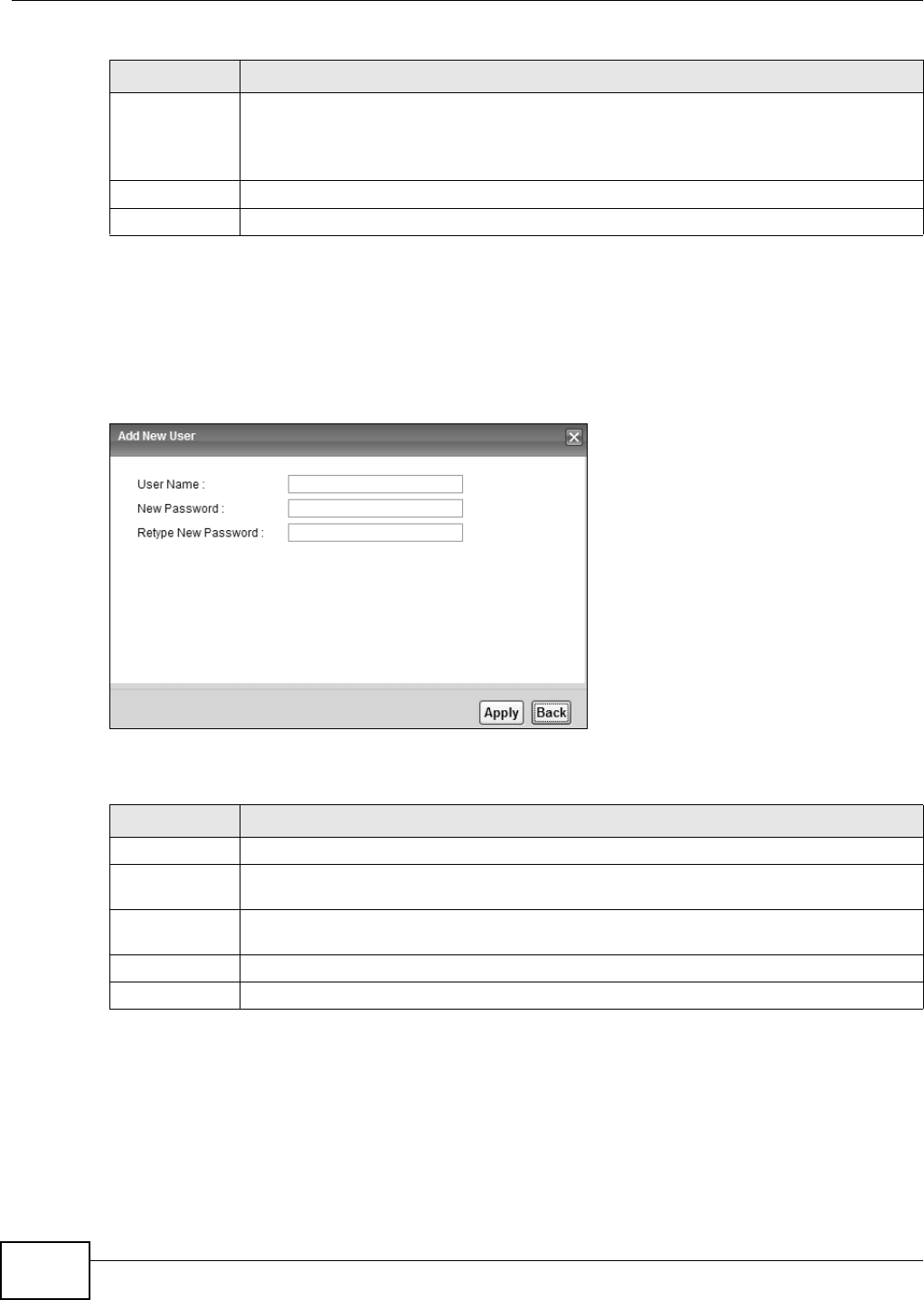
Chapter 13 USB Service
VMG8324-B10A / VMG8324-B30A Series User’s Guide
190
13.2.2 The Add New User Screen
Use t his screen t o create a user account that can access t he secured shares on t he USB device. To
access t his screen, click t he Add new use r but t on in t he N et w or k Se t t ing > USB Service > File
Sha r in g screen.
Figure 109 Network Sett ing > USB Service > File Sharing > Add new user
Each field is described in the following t able.
13.3 The Media Server Screen
The m edia server feat ure let s anyone on your network play video, m usic, and phot os from t he USB
st orage device connect ed t o your Device ( without having t o copy them t o another com puter) . The
Device can funct ion as a DLNA- com pliant m edia server. The Device st r eam s files to DLNA- com pliant
Access Level Select Public t o allow all users on t he net work to access the shared files.
Select Se cu r it y t o require users t o log in to access shared files.
Set up user accounts in t he Accou nt M a nagem e nt sect ion.
Apply Click this to save your changes t o t he Device.
Back Click t his t o ret urn t o t he previous screen.
Table 78 Net work Set t ing > Hom e Net working > File Sharing > Add new share
LABEL DESCRIPTION
Table 79 Net work Set t ing > Hom e Net working > File Sharing > Add new user
LABEL DESCRIPTION
User Nam e Ent er a user nam e. You can ent er up to 16 charact ers. Only let t ers and num bers allowed.
New Password Ent er the passwor d used to access the secured share. The password m ust be 5 to 15
charact ers long. Only let t ers and num bers are allowed. The passw ord is case sensitive.
Ret y pe New
Passw ord
Ret ype t he password t hat you ent ered above.
Apply Click this to save your changes t o t he Device.
Back Click t his t o ret urn t o t he previous screen.
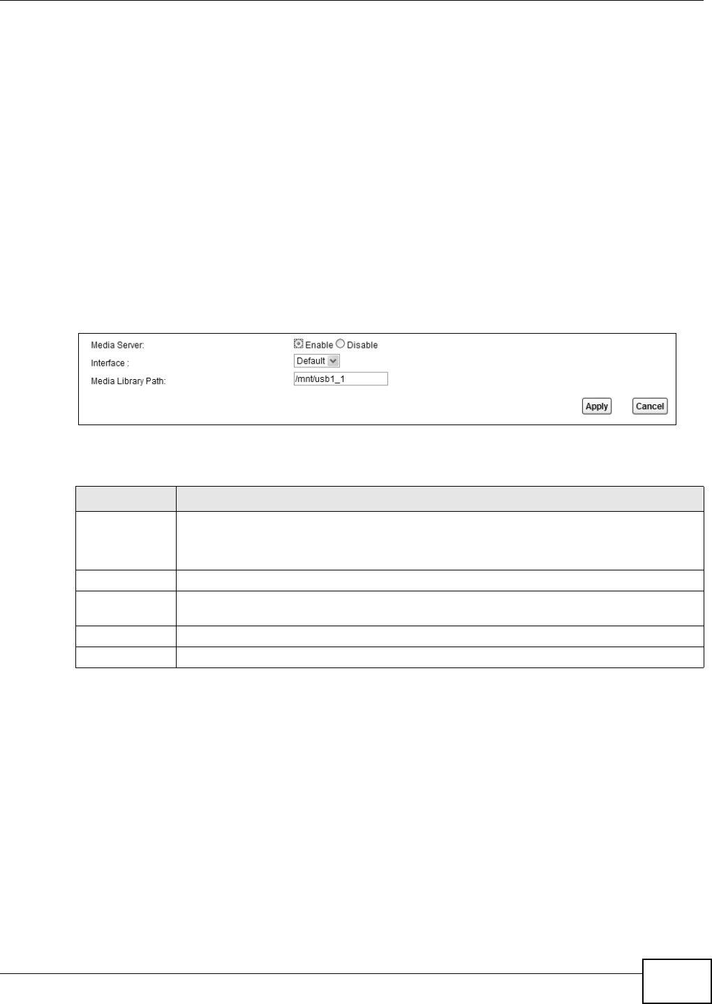
Chapter 13 USB Service
VMG8324-B10A / VMG8324-B30A Series User’s Guide 191
m edia client s ( like Windows Media Player) . The Digit al Living Net work Alliance (DLNA) is a group of
personal com put er and elect ronics com panies t hat works t o m ake product s com pat ible in a hom e
net work.
The Device m edia server enables you to:
• Publish all shares for everyone t o play m edia files in the USB storage device connect ed to the
Device.
• Use hardware- based m edia client s like the DMA- 2500 t o play t he files.
Not e: Anyone on your net work can play the m edia files in t he published shares. No user
nam e and passwor d or ot her form of securit y is used. The m edia ser ver is enabled
by default w it h t he video, phot o, and m usic shares published.
To change your Device’s m edia server set t ings, click Ne t w or k Se t t ing > USB Service > Me dia
Se r v e r. The scr een appears as shown.
Figure 110 Net work Sett ing > USB Service > Media Server
The following t able describes t he labels in this m enu.
13.4 Printer Server
The Device allows you t o shar e a USB print er on your LAN. You can do t his by connecting a USB
print er t o one of the USB por t s on t he Device and t hen configuring a TCP/ I P port on t he com put ers
connect ed to your net w ork.
13.4.1 Before You Begin
To configure t he print server you need t he follow ing:
• Your Device m ust be connect ed t o your com put er and any ot her devices on your net work. The
USB print er m ust be connected to your Device.
Table 80 Net work Sett ing > USB Service > Media Server
LABEL DESCRIPTION
Media Server Select Enable t o have t he Dev ice funct ion as a DLNA- com pliant m edia server.
Enable t he m edia server to let ( DLNA- com pliant) m edia clients on your net w ork play m edia
files locat ed in the shares.
I nterface Select an int erface on w hich you want t o enable t he m edia server funct ion.
Media Librar y
Pat h
Enter t he path client s use to access the m edia files on a USB storage device connect ed to
the Dev ice.
Apply Click Apply t o save your changes.
Cancel Click Ca nce l to rest ore your previously saved set t ings.
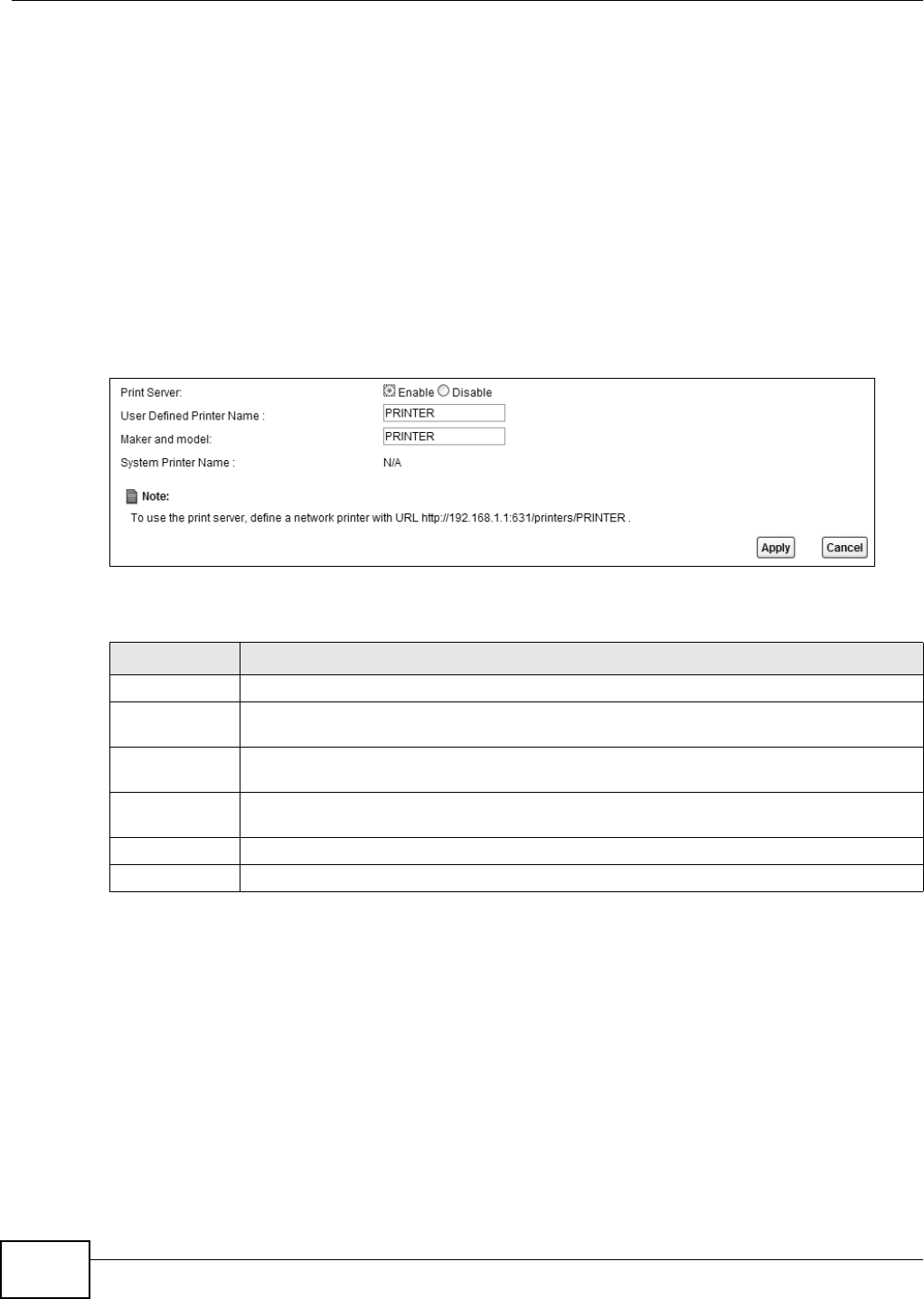
Chapter 13 USB Service
VMG8324-B10A / VMG8324-B30A Series User’s Guide
192
• A USB print er wit h t he driver already installed on your com put er.
• The com put ers on your net work m ust have t he print er software already inst alled before they can
create a TCP/ I P port for printing via t he net work. Follow your printer m anufact urers inst ructions
on how t o inst all t he print er software on your com put er.
Not e: Your print er ’s inst allat ion instructions m ay ask t hat you connect t he print er to your
com put er. Connect your print er to t he Device instead.
13.4.2 The Printer Server Screen
Use t his screen t o enable or disable sharing of a USB print er via your Device.
To access t his screen, click N e t w or k Set t ing > USB Se rvice > Print e r Server.
Figure 111 Network Sett ing > USB Service > Print er Server
The following t able describes t he labels in this m enu.
Table 81 Net work Set t ing > USB Service > Print Server
LABEL DESCRIPTION
Printer Server Select Enable t o have t he Device share a USB printer.
User Defined
Printer Nam e
Type t he nam e for t he print er.
Maker and
m odel
Type up t o 80 characters for t he m anufacturer and m odel num ber of t he printer.
Syst em Print er
Nam e
This field shows the pr int er’s system nam e the Device has det ected from one of t he USB
port s.
Apply Click Apply t o save y our changes.
Cancel Click Can cel t o rest ore your previously saved set t ings.
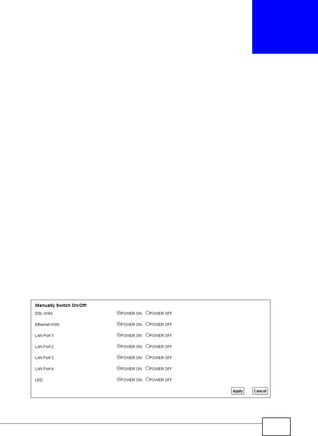
VMG8324-B10A / VMG8324-B30A Series User’s Guide 193
CHAPTER 14
Power Management
14.1 Overview
Power m anagem ent allows you to turn on/ off one or m ore int erfaces and all LED light s w ithout
power off t he whole system when necessary. You can configure a schedule t o do so aut om at ically or
m anually do it on the Web Configurat or.
14.1.1 What You Can Do in this Chapter
• Use the Pow e r Ma n a ge m e nt screen to m anually t urn on/ off interface( s) and/ or LEDs ( Sect ion
14.2 on page 193) .
• Use the Aut o Sw it ch Off screen t o configure schedules for t urning on/ off int erface( s) and/ or
LEDs autom at ically ( Sect ion 14.3 on page 194) .
14.1.2 What You Need To Know
• These screens are only available for t he “ supervisor ” user.
• The Pow e r M ana gem e n t and Au t o Sw it ch Off screens are dependant . You can only configure
the on/ off swit ches of t he sam e interface and LEDs in one of the two screens.
14.2 The Power Management Screen
Use t his screen to m anually t urn on/ off int erface(s) or LEDs. Click Ne t w or k Se t t ing > Pow er
M an age m e nt > Pow er Ma na gem e n t . The screen appears as shown.
Figure 112 Net work Set t ing > Power Managem ent
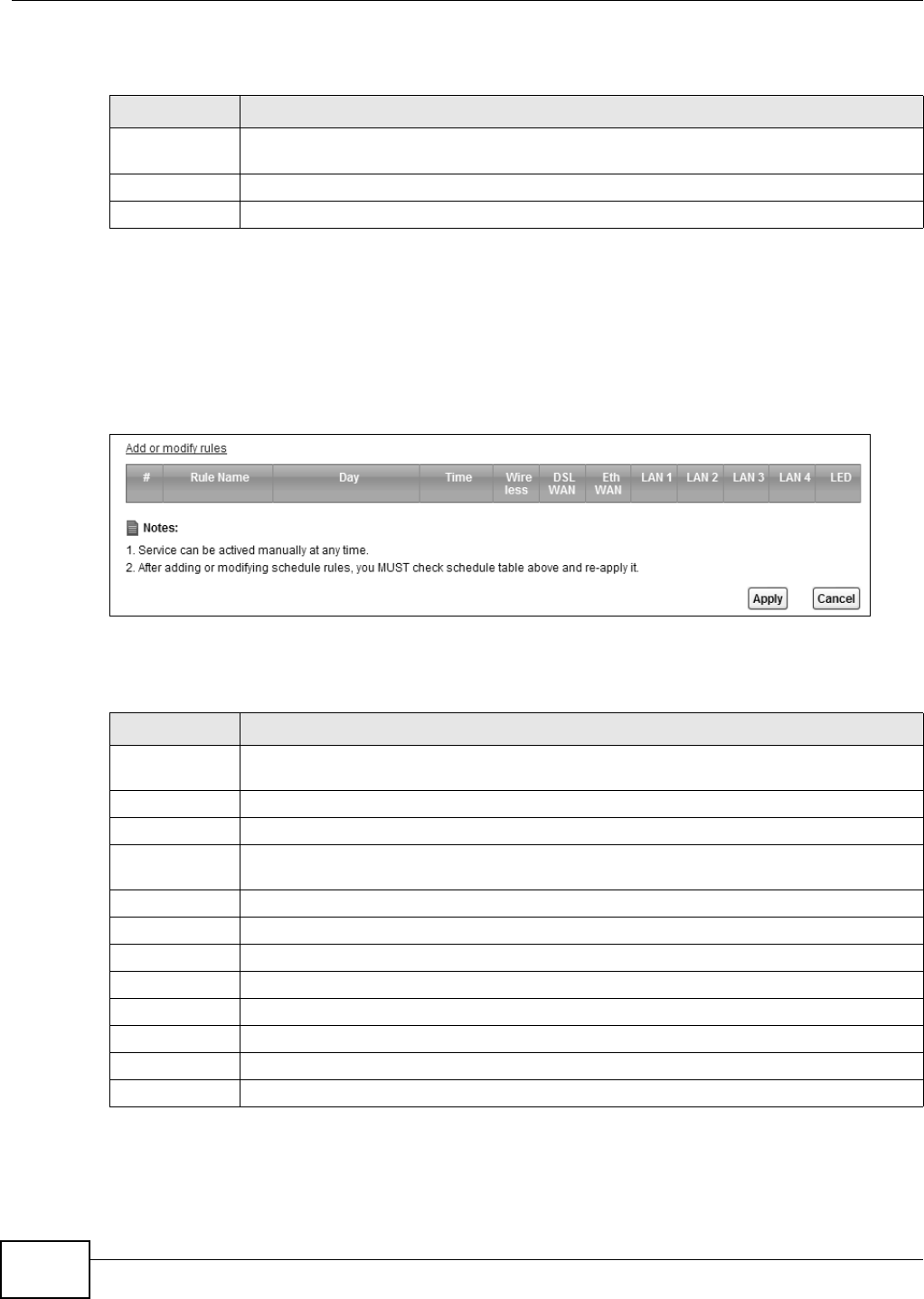
Chapter 14 Power Management
VMG8324-B10A / VMG8324-B30A Series User’s Guide
194
Each field is described in the following t able.
14.3 The Auto Switch Off Screen
Use t his scr een t o view schedules t o t urn on or off specific int er face( s) and/ or all LED light s on t he
Device. To access this screen, click N e t w ork Se t t ing > Pow er M a nagem e nt > Auto Sw it ch Off.
Figure 113 Net work Sett ing > Pow er Managm ent > Aut o Swit ch Off
The following t able describes t he labels in this m enu.
Table 82 Net work Sett ing > Power Managem ent
LABEL DESCRIPTION
Manually
Switch On/ Off
Select POW ER ON or POW ER OFF t o t urn on/ off the int erface or LED light s.
Apply Click Apply t o save your changes.
Cancel Click Ca ncel t o restore your previously saved set t ings.
Table 83 Net work Sett ing > Power Managm ent > Auto Swit ch OffNet work Set t ing > Power
Managm ent > Aut o Sw itch Off
LABEL DESCRIPTION
Add or m odify
rules
Click t his link t o cr eat e or edit a schedule.
#This is t he index num ber of a schedule rule.
Rule Nam e This field shows the nam e of t he schedule rule.
Day This field shows which week days ( in green) t he int erface( s) and/ or LEDs are t urned on and
the days ( grayed- out ) t hey are t urned off aut om at ically.
Tim e This field shows t he t im e per iod t he int erface( s) and/ or LEDs are t urned on.
Wireless This field show s whether this schedule applies t o the wireless LAN int erface.
DSL WAN This field shows whet her this schedule applies to t he DSL WAN int erface.
Eth WAN This field shows whet her t his schedule applies to t he Ethernet WAN int er face.
LAN1~ LAN4 This field show s w het her t his schedule applies to the cor responding LAN int erface.
LED This field shows whet her t his schedule applies t o t he LEDs.
Apply Click Apply t o save your changes.
Cancel Click Ca nce l to rest ore your previously saved set t ings.
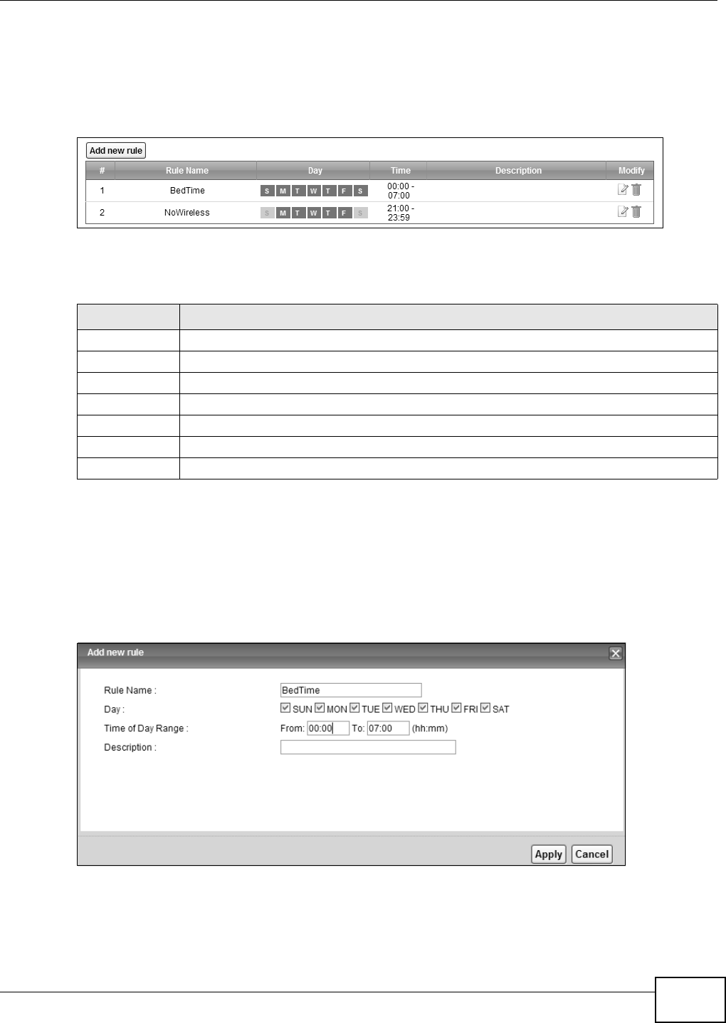
Chapter 14 Power Management
VMG8324-B10A / VMG8324-B30A Series User’s Guide 195
14.3.1 The Auto Switch Off Add/Edit Screen
Use t his screen to m anage t he aut o switch off schedules. To access t his screen, click t he Add or
m odify rules link in t he N et w or k Set t ing > Pow e r M a n a ge m ent > Au t o Sw itch Off screen.
Figure 114 Net work Sett ing > Pow er Managm ent > Aut o Swit ch Off > Add or m odify rules
The following t able describes t he labels in this m enu.
14.3.2 The Add/Edit Rule Screen
Use t his screen to configure a schedule rule. To access t his screen, click the Add n e w rule link or
the Ed it icon in t he N e t w or k Set t in g > Pow e r M a nagem ent > Aut o Sw itch Off > Add or
m odify rules screen.
Figure 115 Net work Sett ing > Pow er Managem ent > Auto Swit ch Off > Add or m odify rules > Add
new rule/ Edit
Table 84 Net work Sett ing > Power Managm ent > Aut o Swit ch Off Net work Sett ing > Power
Managm ent > Aut o Sw it ch Off > Add or m odify rules
LABEL DESCRIPTION
Add new rule Click t his link t o creat e a rule.
#This is t he index num ber of a r ule.
Rule Nam e This field shows the nam e of t he rule.
Day This field shows t he week days of the schedule ( in green) .
Tim e This field shows t he t im e period of t he schedule.
Descript ion This field shows m ore inform at ion about this rule.
Modify Click t he Ed it icon t o m odify the rule or click t he D e le t e icon t o rem ove it.

Chapter 14 Power Management
VMG8324-B10A / VMG8324-B30A Series User’s Guide
196
Each field is described in the following t able.
Table 85 Net work Set t ing > Power Managem ent > Aut o Switch Off > Add or m odify rules > Add
new rule/ Edit >
LABEL DESCRIPTION
Rule Nam e Type up to 31 alphanum beric charact ers for t he nam e of t his rule.
Day Select the week day( s) of t he schedule.
Tim e of Day
Range
Ent er t he Fr om and To t im es ( in hh: m m form at) t o set a tim e period for t he schedule. You
can only enter a t im e period between 00: 00 and 23: 59.
To set a t im e period crossing over m idnight, you m ust split t he t im e period into t wo
schedule rules. For exam ple, for a tim e period from 10: 00 PM t o t he next day’s 8: 00 AM,
you can set one schedule for 22: 00~ 23: 59 and anot her schedule for 00: 00~ 08: 00.
Descript ion Ent er m or e inform at ion for this rule here.
Apply Click Apply t o save your changes.
Cancel Click Ca ncel t o restore your previously saved set t ings.
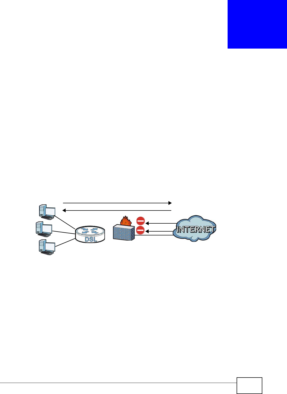
VMG8324-B10A / VMG8324-B30A Series User’s Guide 197
CHAPTER 15
Firewall
15.1 Overview
This chapt er shows you how t o enable and configure t he Device’s security set t ings. Use t he firewall
to pr otect your Device and network from at t acks by hackers on t he I nternet and control access t o
it . By default t he firewall:
• allows t raffic that originates from your LAN com puters to go t o all ot her networks.
• blocks traffic t hat originat es on ot her net w orks from going t o t he LAN.
The following figure illust rat es t he default firewall action. User A can initiat e an I M ( I nstant
Messaging) session from t he LAN t o the WAN ( 1) . Ret urn t raffic for this session is also allowed (2) .
However ot her t raffic init iated from t he WAN is blocked (3 and 4) .
Figure 116 Default Fir ewall Action
15.1.1 What You Can Do in this Chapter
• Use the Ge n e r al screen t o configure t he security level of the firewall on t he Device ( Sect ion 15.2
on page 199) .
• Use the Pr otocol screen t o add or rem ove predefined I nt ernet services and configure firewall
rules ( Sect ion 15.3 on page 199) .
• Use the Acce ss Cont r ol screen to view and configure incom ing/ outgoing filt ering rules ( Section
15.4 on page 201) .
• Use the DoS screen t o act ivat e protect ion against Denial of Service ( DoS) att acks ( .Sect ion 15.5
on page 204) .
WAN
LAN
3
4
1
2
A

Chapter 15 Firewall
VMG8324-B10A / VMG8324-B30A Series User’s Guide
198
15.1.2 What You Need to Know
SYN Attack
A SYN att ack floods a target ed syst em wit h a series of SYN packet s. Each packet causes t he
target ed syst em t o issue a SYN-ACK response. While the target ed syst em waits for t he ACK t hat
follows the SYN- ACK, it queues up all out st anding SYN- ACK responses on a backlog queue. SYN-
ACKs are m oved off the queue only when an ACK com es back or when an int ernal t im er t erm inat es
the three- way handshake. Once t he queue is full, t he syst em will ignore all incom ing SYN requests,
m aking the system unavailable for legit im at e users.
DoS
Denials of Service ( DoS) att acks are aim ed at devices and net w orks wit h a connect ion to the
I nt ernet . Their goal is not t o st eal infor m at ion, but to disable a device or net w ork so users no longer
have access t o net w ork resources. The ZyXEL Device is pre- configured t o aut om at ically det ect and
thwart all known DoS at tacks.
DDoS
A DDoS att ack is one in which m ult iple com prom ised syst em s at t ack a single target , thereby
causing denial of service for users of t he target ed syst em .
LAND Attack
I n a LAND att ack, hackers flood SYN packet s int o t he network wit h a spoofed source I P addr ess of
the target syst em . This m akes it appear as if the host com put er sent t he packets to it self, m aking
the syst em unavailable while t he t arget syst em tries t o respond to it self.
Ping of Death
Ping of Deat h uses a " ping" utility t o create and send an I P packet t hat exceeds t he m axim um
65,536 bytes of dat a allowed by the I P specificat ion. This m ay cause system s t o crash, hang or
reboot.
SPI
St at eful Packet I nspection ( SPI ) t racks each connection crossing the firewall and m akes sur e it is
valid. Filt ering decisions are based not only on rules but also context . For exam ple, t raffic from the
WAN m ay only be allowed t o cross t he firewall in response to a request from t he LAN.
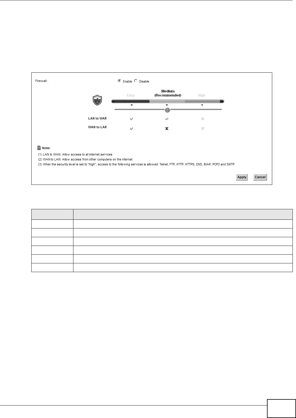
Chapter 15 Firewall
VMG8324-B10A / VMG8324-B30A Series User’s Guide 199
15.2 The Firewall Screen
Use t his scr een t o set t he securit y level of the firewall on t he Device. Firewall rules are grouped
based on the direct ion of t ravel of packet s t o which t hey apply.
Click Se cu r it y > Firew a ll t o display the Gene r a l screen.
Figure 117 Security > Firewall > General
The following t able describes t he labels in this screen.
15.3 The Protocol Screen
You can configure cust om ized services and port num bers in t he Pr ot ocol screen. For a
com prehensive list of por t num bers and services, visit t he I ANA ( I nt ernet Assigned Num ber
Aut hority) w ebsite. See Appendix G on page 397 for som e exam ples.
Table 86 Securit y > Firewall > General
LABEL DESCRIPTION
Firewall Select Enable t o act ivate t he firewall feat ure on the Device.
Easy Select Ea sy t o allow LAN t o WAN and WAN t o LAN packet direct ions.
Medium Select Med iu m to allow LAN to WAN but deny WAN to LAN packet direct ions.
High Select High t o deny LAN t o WAN and WAN t o LAN packet direct ions.
Apply Click App ly t o save your changes.
Cancel Click Ca nce l t o rest ore your previously saved settings.
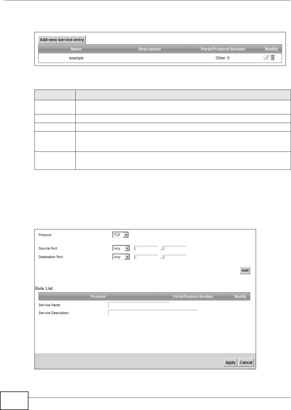
Chapter 15 Firewall
VMG8324-B10A / VMG8324-B30A Series User’s Guide
200
Click Se cu r it y > Firew a ll > Prot ocol t o display t he following screen.
Figure 118 Securit y > Firewall > Protocol
The following t able describes t he labels in this screen.
15.3.1 Add/Edit a Service
Use t his screen to add a cust om ized service rule t hat you can use in the firewall’s ACL rule
configurat ion. Click Add new ser vice ent ry or t he edit icon next t o an exist ing service rule in t he
Se r v ice screen to display t he following screen.
Figure 119 Service: Add/ Edit
Table 87 Securit y > Firewall > Prot ocol
LABEL DESCRIPTION
Add new
service entry
Click this to add a new service.
Nam e This is t he nam e of your cust om ized service.
Descript ion This is t he descript ion of your cust om ized service.
Port s/ Prot ocol
Nu m ber
This shows t he I P prot ocol (TCP, UDP, I CMP, or TCP/ UDP) and the port num ber or range
of port s that defines your cust om ized serv ice. Ot h e r and t he prot ocol num ber displays if t he
service uses another I P prot ocol.
Modify Click t he Ed it icon t o edit t he ent r y.
Click the D ele t e icon to rem ove t his ent ry.
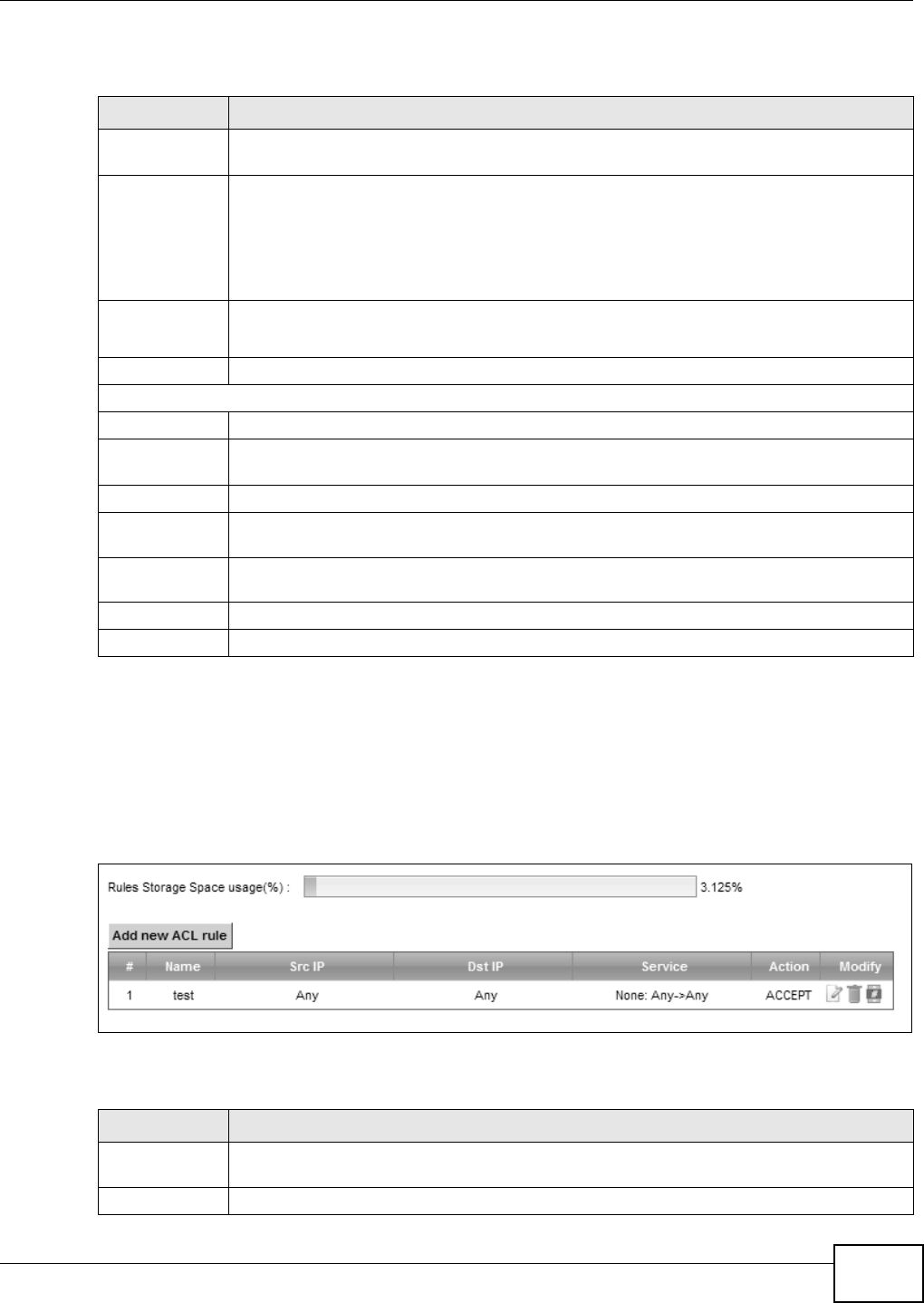
Chapter 15 Firewall
VMG8324-B10A / VMG8324-B30A Series User’s Guide 201
The following t able describes t he labels in this screen.
15.4 The Access Control Screen
Click Securit y > Fire w all > Acce ss Cont rol t o display t he following screen. This scr een displays a
list of the configured incom ing or outgoing filt ering rules.
Figure 120 Security > Firewall > Access Control
The following t able describes t he labels in this screen.
Table 88 Service: Add/ Edit
LABEL DESCRIPTION
Prot ocol Choose t he I P protocol ( TCP, UD P, I CM P, or O t he r ) t hat defines your custom ized port from
the drop-down list box . Select Ot h er t o be able t o ent er a prot ocol num ber.
Source/
Dest ination Port
These fields are displayed if you select TCP or UDP as the I P port .
Select Single t o specify one port only or Ra nge to specify a span of port s t hat define your
cust om ized service. I f you select An y, t he service is applied t o all ports.
Type a single port num ber or the range of por t num bers t hat define your custom ized
service.
Prot ocol
Nu m ber
This field is displayed if you select O t he r as the protocol.
Enter t he prot ocol num ber of your cust om ized port .
Add Click t his t o add the prot ocol to t he Ru le List below.
Rule List
Prot ocol This is t he I P port (TCP, UD P, I CMP, or Ot h e r) t hat defines your cust om ized port .
Port s/ Prot ocol
Nu m ber
For TCP, UDP, I CMP, or TCP/ UDP protocol rules t his shows the port num ber or range t hat
defines t he cust om service. For other I P protocol rules this shows t he prot ocol num ber.
Delet e Click t he Dele t e icon t o rem ove t he rule.
Service Nam e Ent er a unique nam e ( up t o 32 print able English keyboard charact ers, including spaces) for
your cust om ized port .
Service
Descript ion
Ent er a descript ion for your cust om ized port .
Apply Click Apply t o save your changes.
Cancel Click Ca nce l to exit t his screen w it hout saving.
Table 89 Securit y > Firewall > Access Cont rol
LABEL DESCRIPTION
Add new ACL
rule
Click t his t o go t o add a filter rule for incom ing or outgoing I P traffic.
#This is t he index num ber of t he entry.
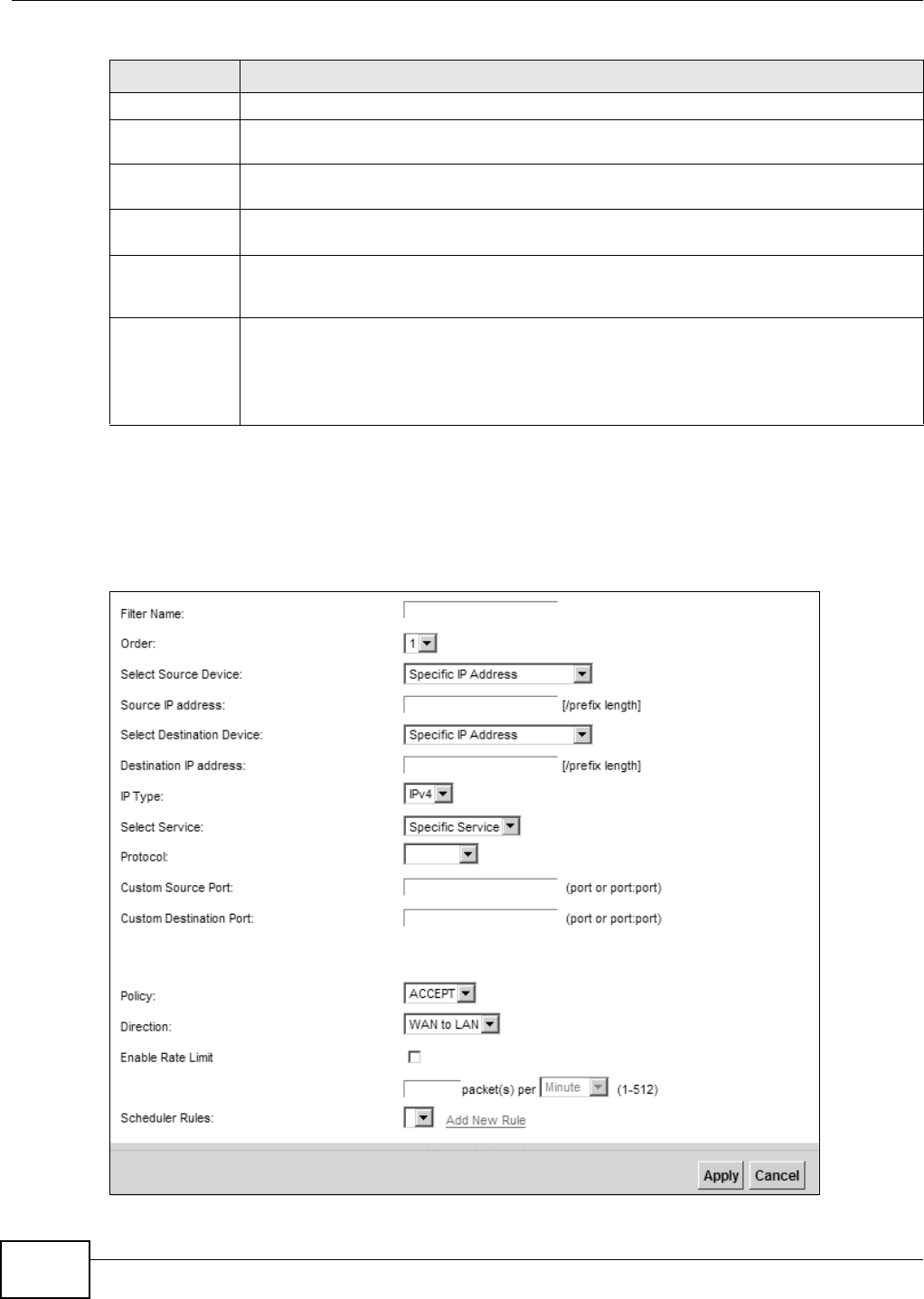
Chapter 15 Firewall
VMG8324-B10A / VMG8324-B30A Series User’s Guide
202
15.4.1 Add/Edit an ACL Rule
Click Add new ACL r u le or t he Ed it icon next to an exist ing ACL rule in t he Access Con t r ol
screen. The following screen displays.
Figure 121 Access Cont rol: Add/ Edit
Nam e This displays t he nam e of t he rule.
Src I P This display s t he source I P addresses to which this rule applies. Please not e that a blank
source address is equivalent t o Any.
Dst I P This displays t he destinat ion I P addr esses t o w hich t his rule applies. Please not e t hat a
blank destinat ion address is equivalent t o Any.
Service This displays t he t ransport layer protocol t hat defines the service and t he dir ection of t raffic
to which this rule applies.
Act ion This field displays whet her the rule silent ly discards packet s ( D ROP) , discards packet s and
sends a TCP r eset packet or an I CMP dest inat ion-unreachable m essage to t he sender
(REJECT) or allows t he passage of packet s ( ACCEPT) .
Modify Click t he Ed it icon t o edit the rule.
Click the D ele t e icon t o d elet e an ex ist ing r u le. Not e t hat subsequ ent r ules m ov e up by on e
when you t ake t his act ion.
Click the Move To icon t o change the order of t he rule. Ent er t he num ber in t he # field.
Table 89 Securit y > Firewall > Access Cont r ol ( continued)
LABEL DESCRIPTION

Chapter 15 Firewall
VMG8324-B10A / VMG8324-B30A Series User’s Guide 203
The following t able describes t he labels in this screen.
Table 90 Access Cont rol: Add/ Edit
LABEL DESCRIPTION
Filt er Nam e Ent er a descript ive nam e of up t o 16 alphanum eric charact ers, not including spaces,
under scor es, and dashes.
You m ust enter t he filt er nam e t o add an ACL rule. This field is read- only if you are edit ing
the ACL rule.
Order Select t he order of t he ACL rule.
Select Source
Device
Select the source dev ice t o which t he ACL rule applies. I f you select Specific I P Address,
enter t he source I P addr ess in t he field below.
Source I P
Address
Ent er t he source I P address.
Select
Dest ination
Device
Select t he dest inat ion device t o which t he ACL rule applies. I f you select Spe cific I P
Address, ent er the dest iniat ion I P address in the field below.
Dest ination I P
Address
Ent er t he dest inat ion I P address.
I P Type Select whet her your I P ty pe is I Pv4 or I Pv6 .
Select Prot ocol Select t he t ransport layer prot ocol that defines your cust om ized por t from t he drop- down
list box. The specific prot ocol rule sets you add in t he Se cur it y > Fir ew a ll > Service >
Add screen display in this list .
I f you want t o configure a cust om ized prot ocol, select Spe cific Service.
Prot ocol This field is displayed only when you select Specific Prot ocol in Sele ct Prot ocol.
Choose t he I P port ( TCP/ UDP, TCP, UDP, I CMP, or I CMPv6 ) that defines your cust om ized
port from t he drop- down list box.
Cust om Source
Port
This field is displayed only when you select Spe cific Pr ot ocol in Se le ct Pr ot ocol.
Ent er a single port num ber or t he range of port num bers of the source.
Cust om
Dest ination Port
This field is displayed only when you select Spe cific Pr ot ocol in Se le ct Pr ot ocol.
Ent er a single port num ber or t he range of port num bers of t he dest inat ion.
Policy Use t he drop- down list box t o select whet her to discard ( D ROP) , deny and send an I CMP
dest inat ion- unreachable m essage t o t he sender of ( REJECT) or allow t he passage of
(ACCEPT) packets t hat m atch t his rule.
Dir ect ion Use t he dr op- down list box t o select t he direction of t raffic t o which t his rule applies.
Enable Rate
Lim it
Select this check box t o set a lim it on t he upst ream / downstream transm ission rate for the
specified prot ocol.
Specify how m any packet s per m inut e or second t he t ransm ission rate is.
Scheduler Rules Select a schedule rule for t his ACL r ule for m t he drop-down list box. You can configure a
new schedule rule by click Add N ew Ru le. This will bring you t o t he Secu r ity > Sch e dule r
Ru les screen.
Apply Click Apply t o save your changes.
Cancel Click Ca nce l to exit t his screen wit hout saving.
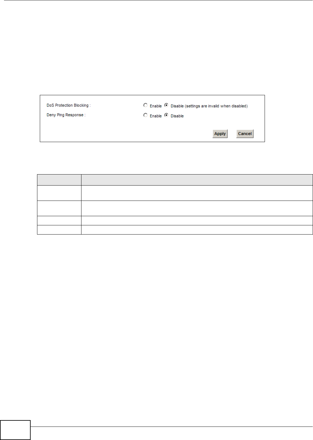
Chapter 15 Firewall
VMG8324-B10A / VMG8324-B30A Series User’s Guide
204
15.5 The DoS Screen
DoS ( Denial of Ser vice) at t acks can flood your I nt ernet connection with invalid packets and
connect ion requests, using so m uch bandwidt h and so m any resources t hat I nt er net access
becom es unavailable.
Use t he D oS screen t o act ivat e protect ion against DoS at t acks. Click Securit y > Fir e w all > D oS
to display t he following screen.
Figure 122 Security > Firewall > DoS
The following t able describes t he labels in this screen.
Table 91 Securit y > Firewall > DoS
LABEL DESCRIPTION
DoS Protect ion
Blocking
Select En a ble t o enable prot ect ion against DoS at t acks.
Deny Ping
Response
Select Enable to block ping request packets.
Apply Click Apply t o save y our chan ges.
Cancel Click Ca ncel t o exit t his screen wit hout saving.
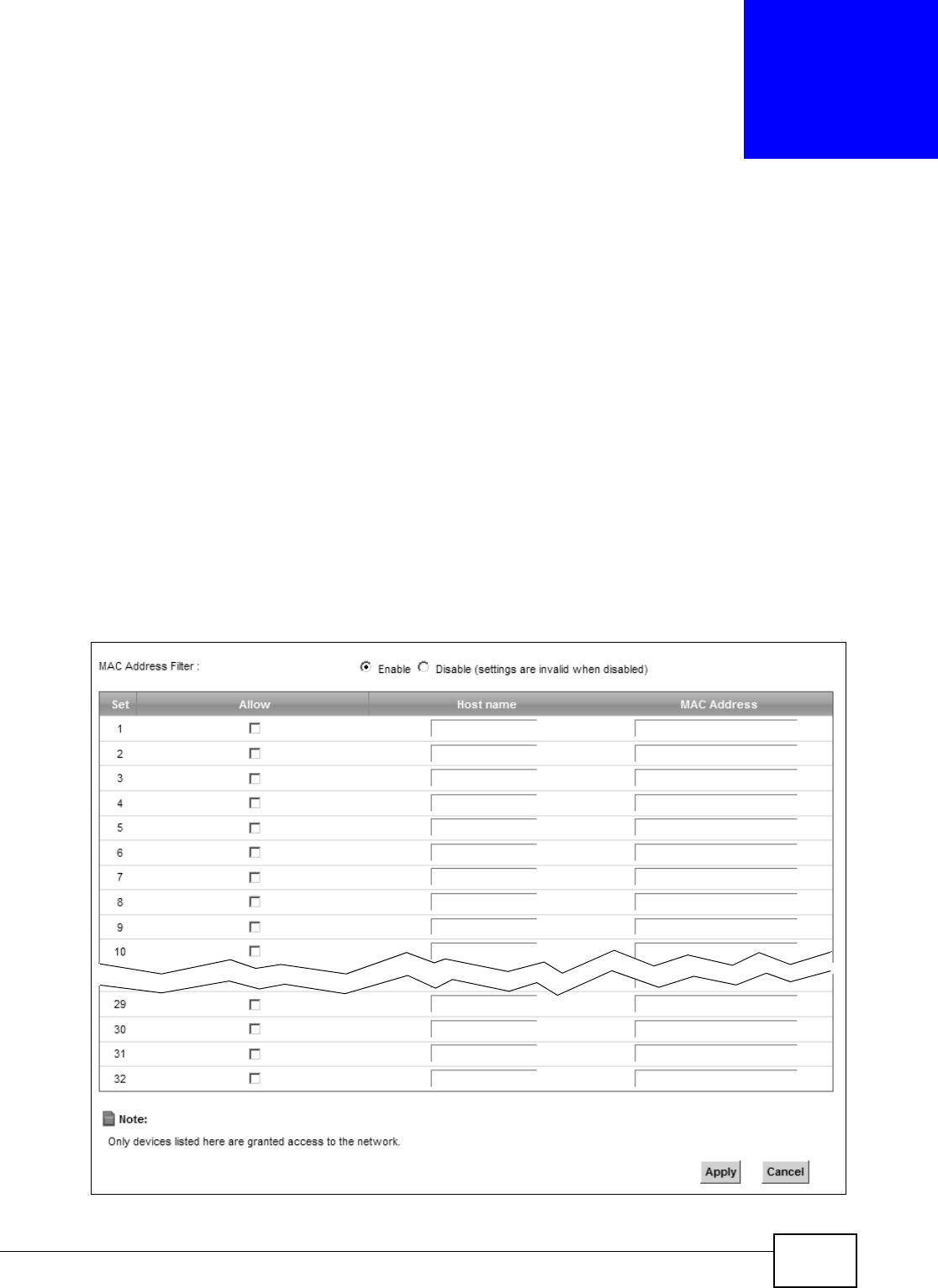
VMG8324-B10A / VMG8324-B30A Series User’s Guide 205
CHAPTER 16
MAC Filter
16.1 Overview
You can configure t he Device to perm it access to clients based on t heir MAC addresses in t he M AC
Filt e r screen. This applies t o wired and wireless connect ions. Every Et hernet device has a unique
MAC ( Media Access Control) address. The MAC address is assigned at t he fact ory and consist s of six
pairs of hexadecim al charact ers, for exam ple, 00: A0: C5: 00: 00: 02. You need t o know the MAC
addresses of the devices t o configure t his screen.
16.2 The MAC Filter Screen
Use t his scr een t o allow wireless and LAN client s access to the Device. Click Securit y > M AC Filt e r.
The screen appears as shown.
Figure 123 Security > MAC Filt er

Chapter 16 MAC Filter
VMG8324-B10A / VMG8324-B30A Series User’s Guide
206
The following t able describes t he labels in this screen.
Table 92 Securit y > MAC Filter
LABEL DESCRIPTION
MAC Address Filt er Select En a ble t o activat e t he MAC filter funct ion.
Set This is the index num ber of t he MAC address.
Allow Select Allow t o perm it access t o t he Device. MAC addresses not list ed will be denied
access to the Device.
I f you clear this, the MAC Address field for this set clears.
Host nam e Ent er t he host nam e of t he wir eless or LAN clients t hat are allowed access to the
Dev ice.
MAC Address Enter t he MAC addresses of t he wireless or LAN client s t hat are allowed access t o t he
Device in t hese address fields. Ent er t he MAC addresses in a valid MAC address form at ,
that is, six hex adecim al charact er pairs, for exam ple, 12: 34: 56: 78: 9a: bc.
Apply Click Apply t o save your changes.
Cancel Click Ca n ce l to rest or e your previously saved settings.