ZyXEL Communications X550NHV2 High-gain Wireless N Gigabit Router User Manual 2
ZyXEL Communications Corporation High-gain Wireless N Gigabit Router 2
UserManual.wiki
>
ZyXEL Communications
>
X550NHV2 User Manual
>
User Manual 2
Contents
1.
User Manual 1
2.
User Manual 2
3.
User Manual 3
User Manual 2
Navigation menu
Upload a User Manual
Namespaces
Wiki Guide
HTML
PDF
Info
Views
User Manual
Discussion / Help
Navigation

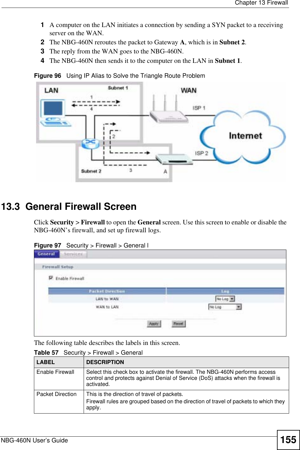
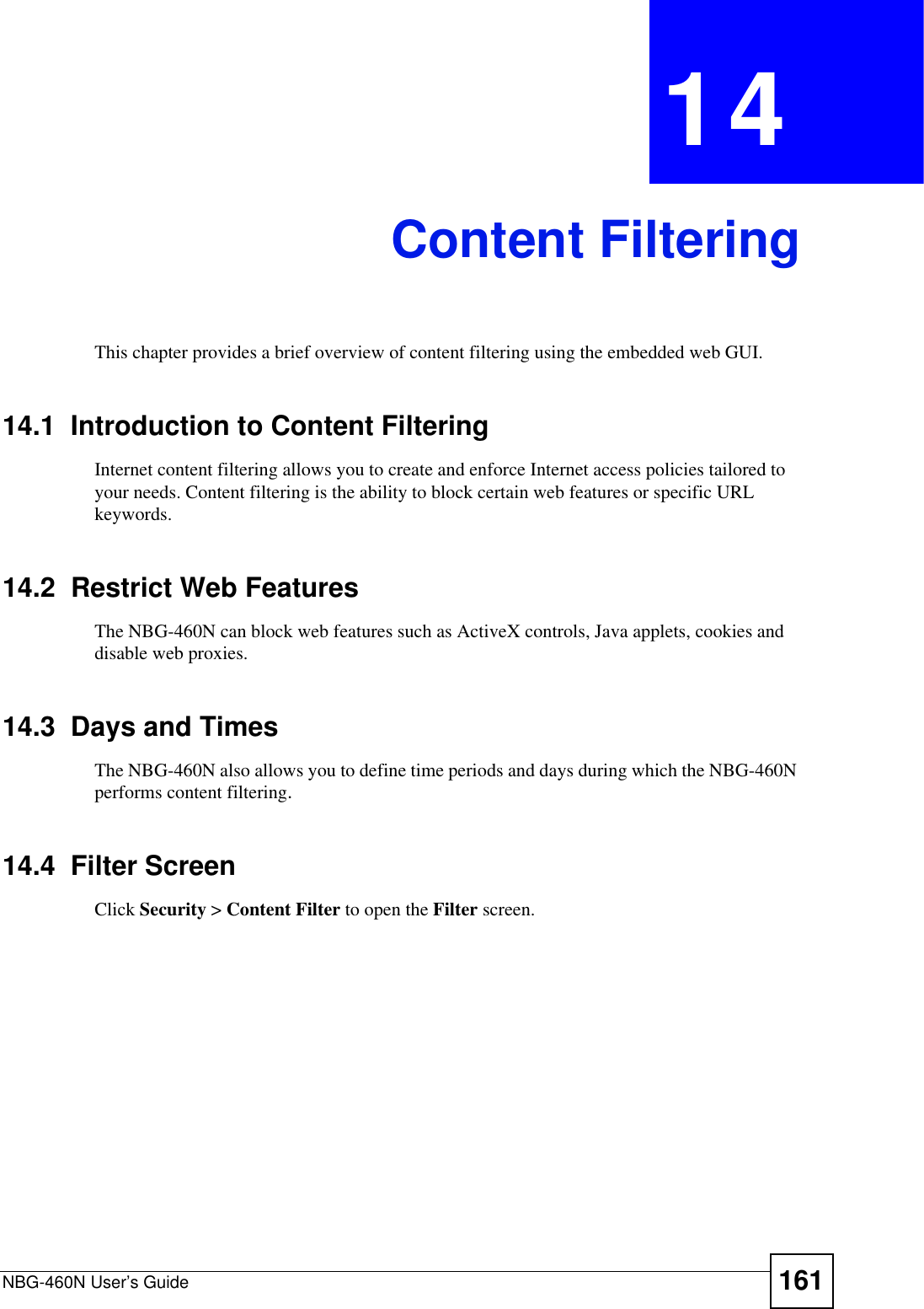
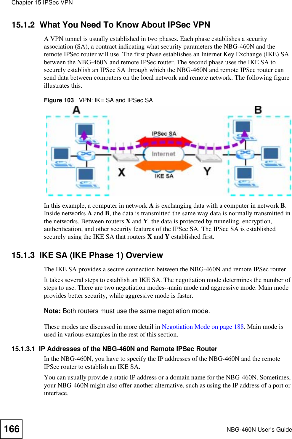
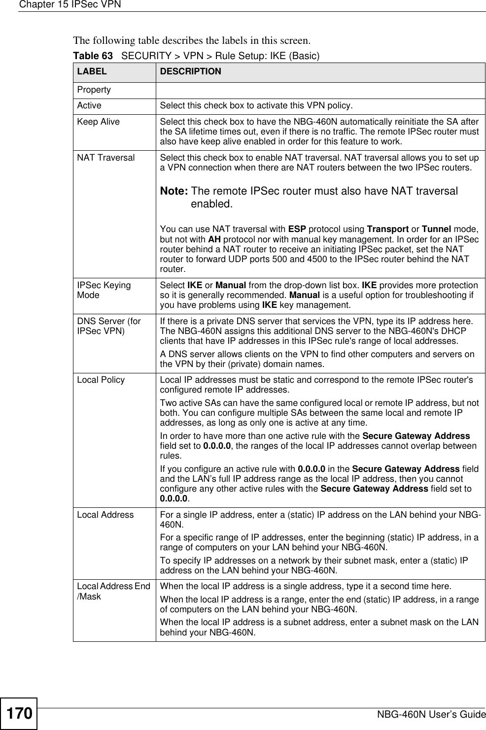
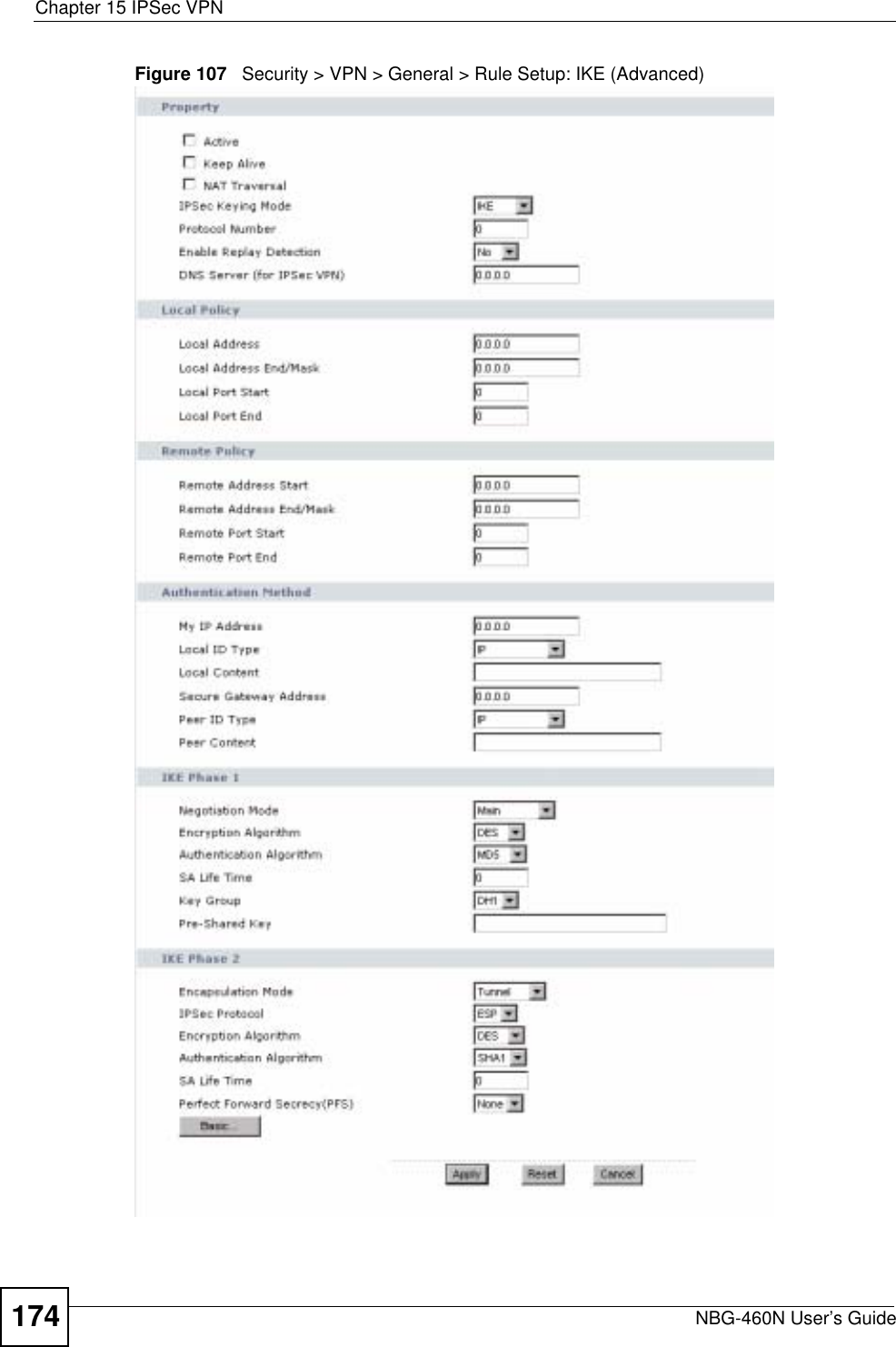
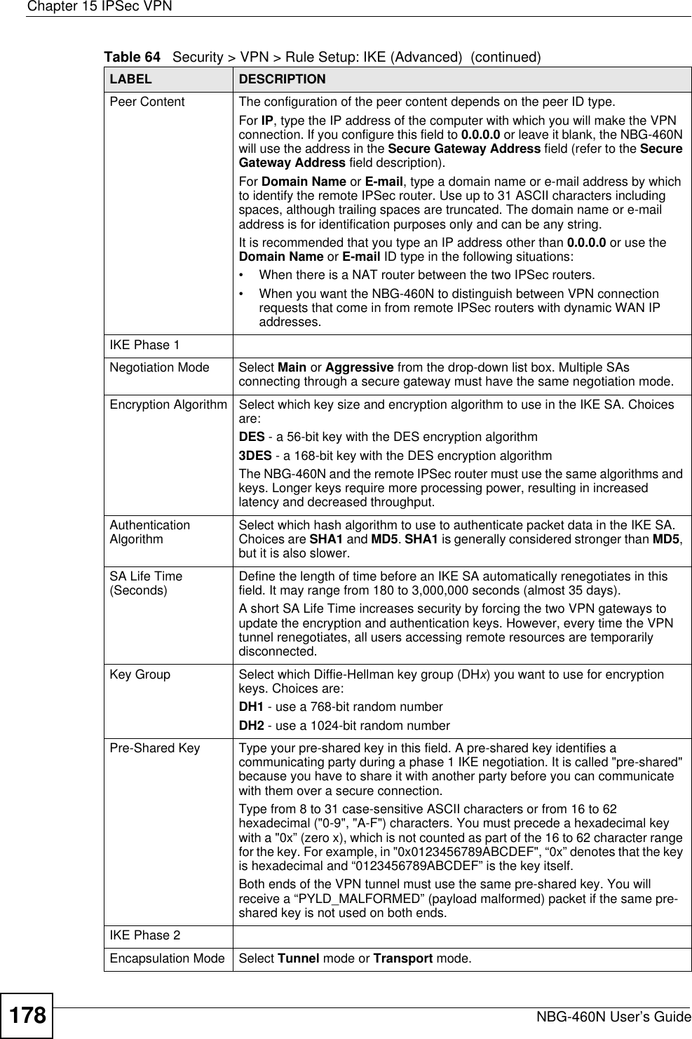
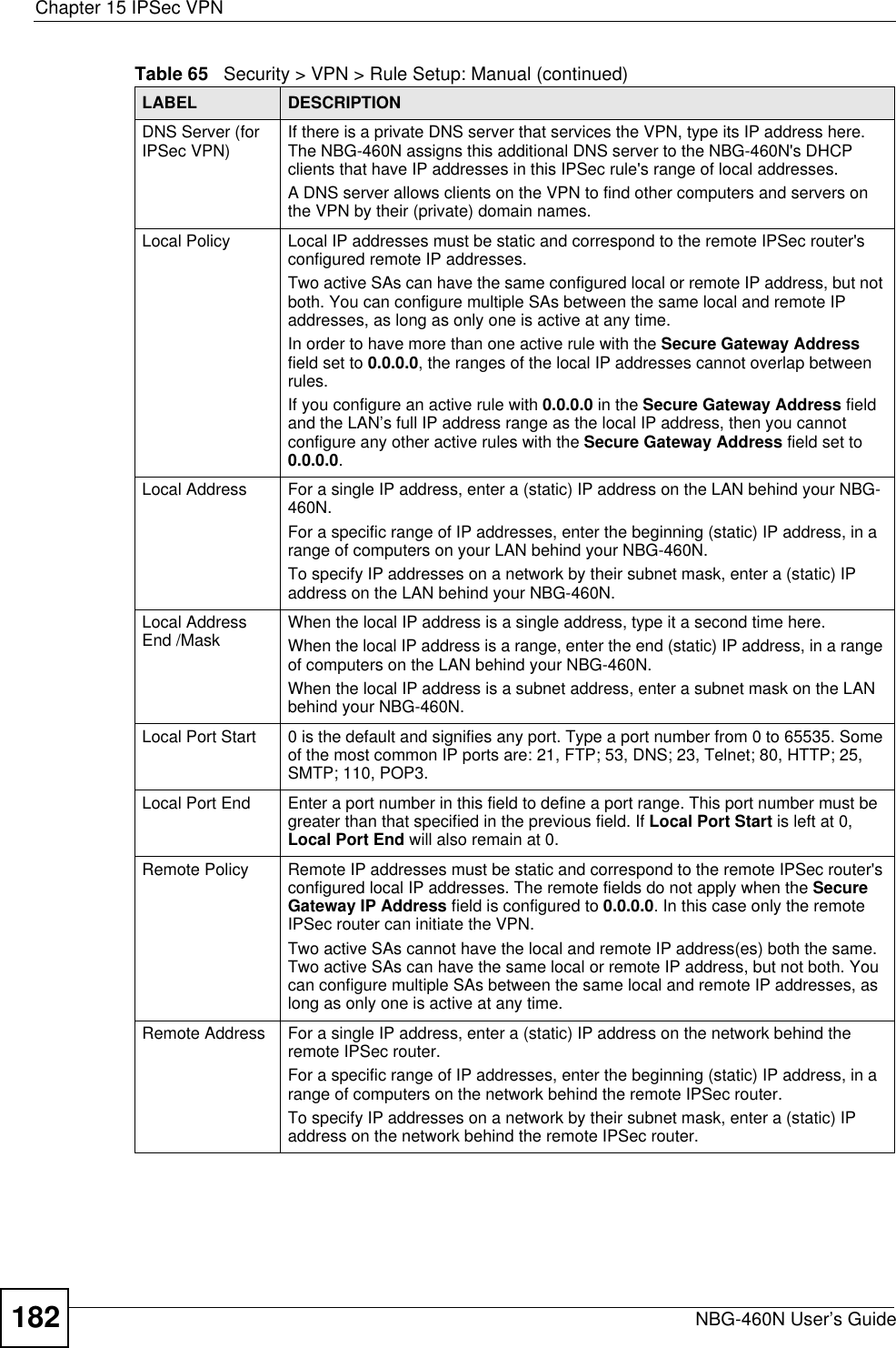
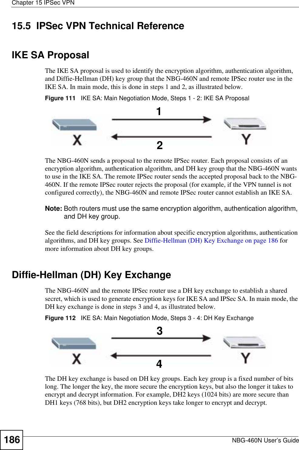
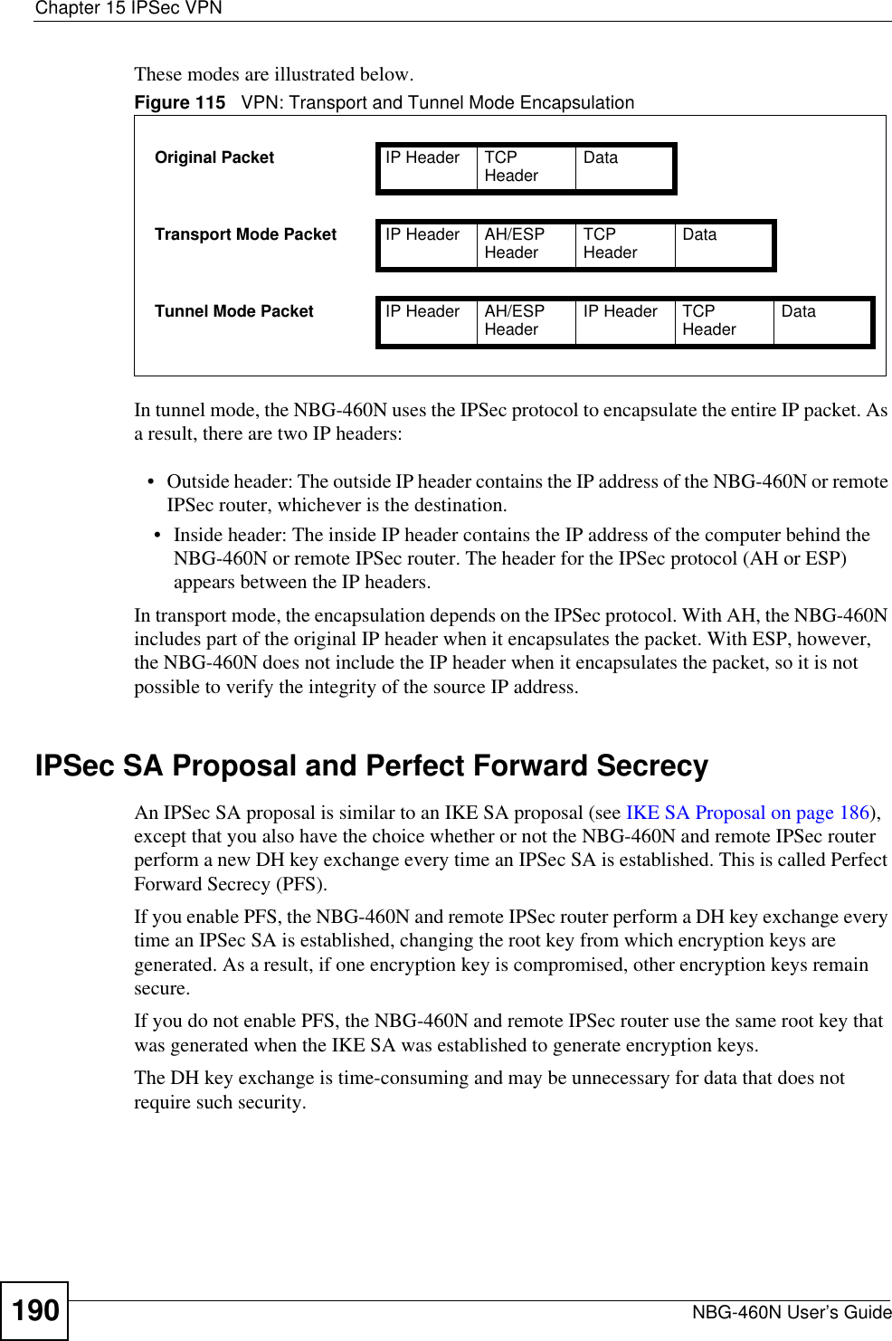
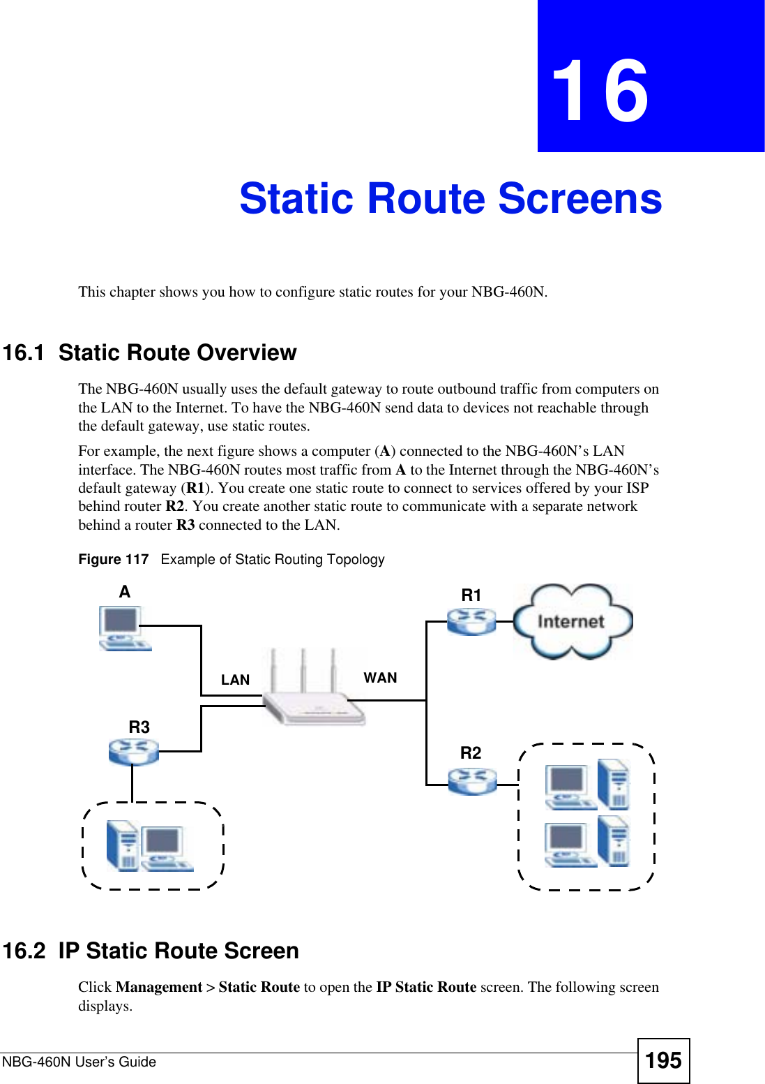
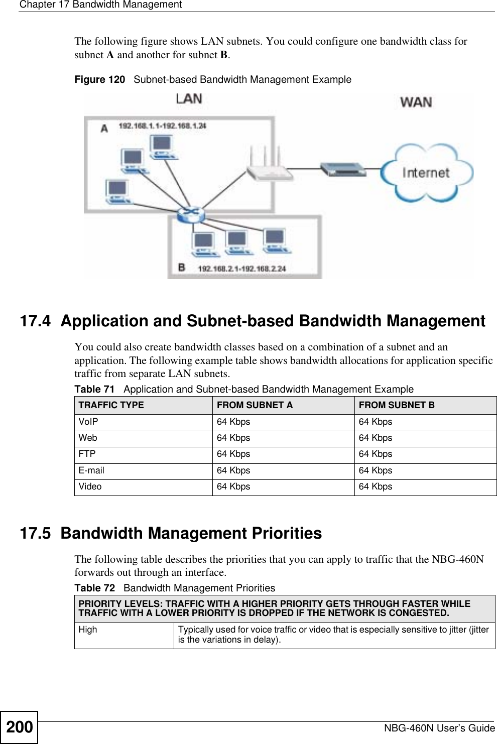
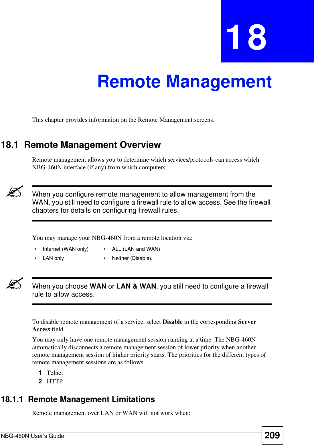
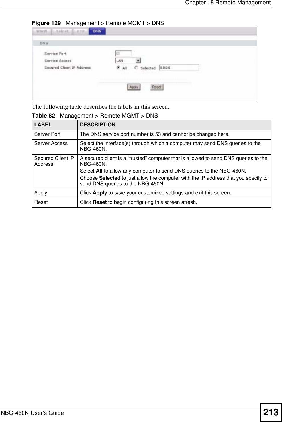
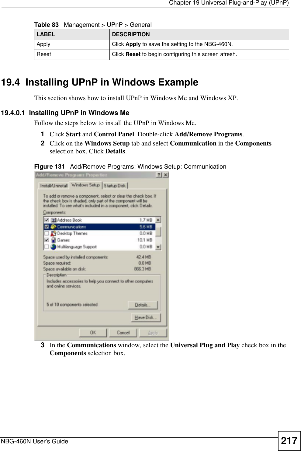
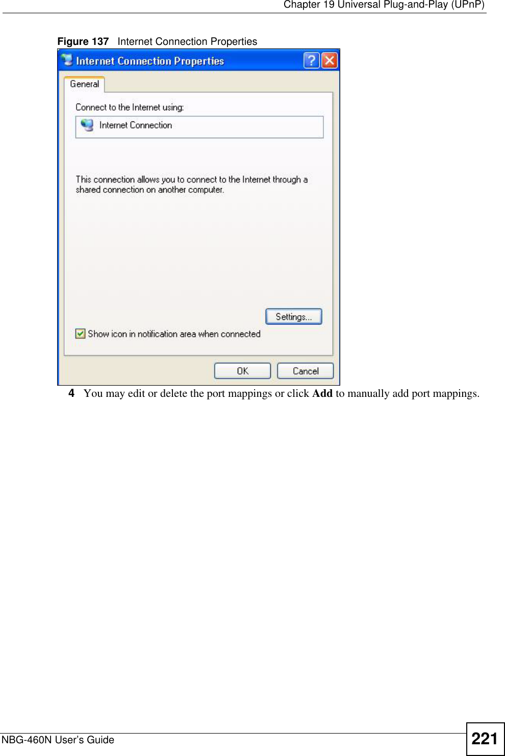
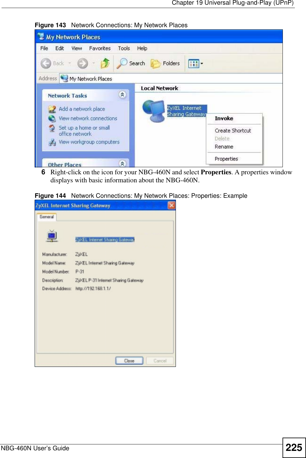
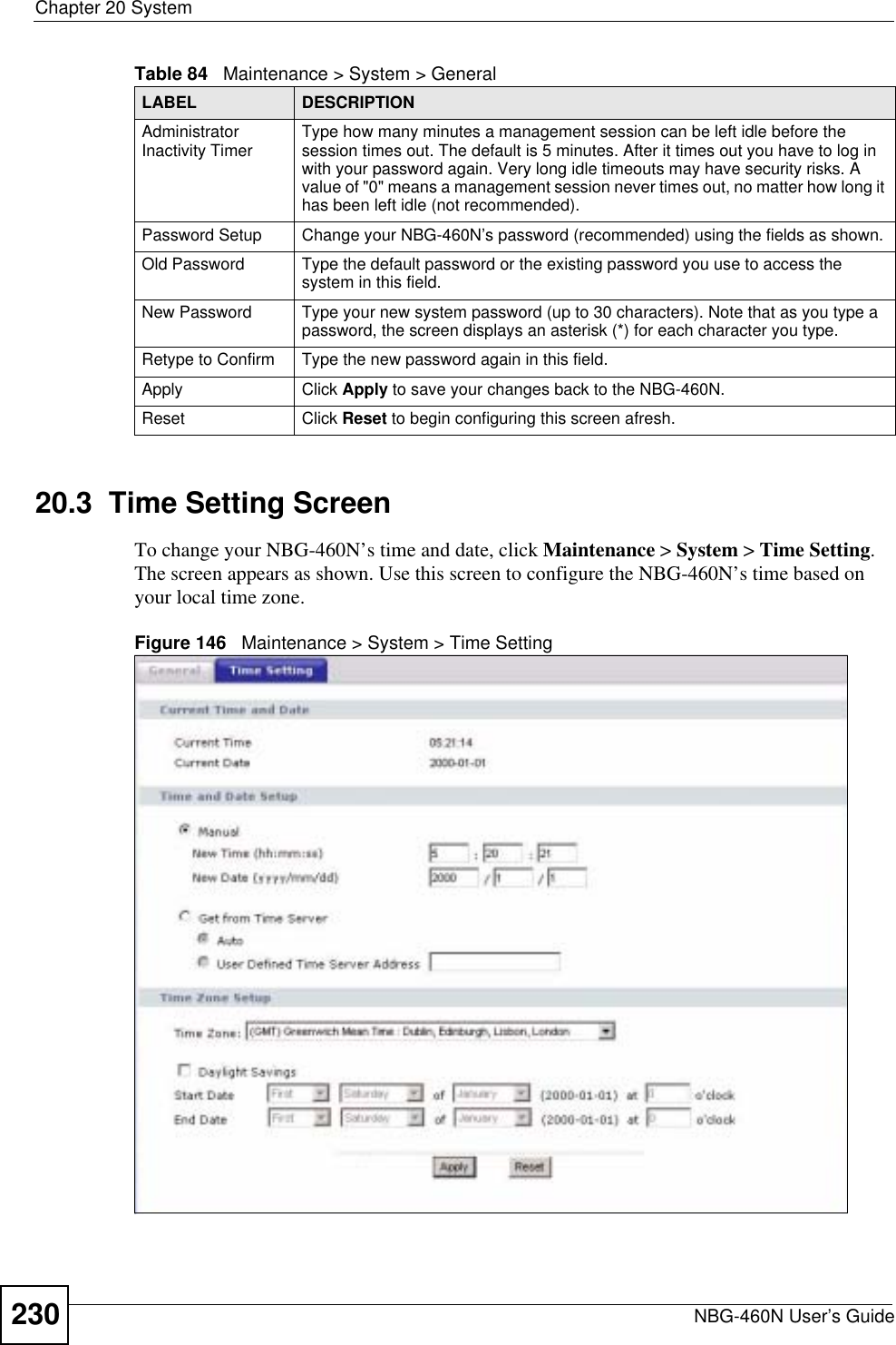
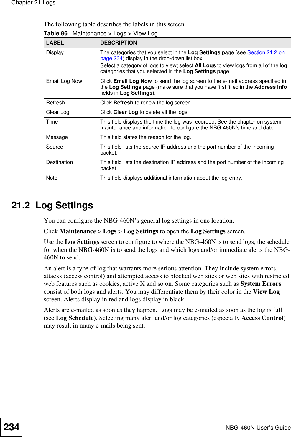
![Chapter 13 FirewallNBG-460N User’s Guide 15713.4.1 The Add Firewall Rule ScreenIf you click Add or the Modify icon on an existing rule, the Add Firewall Rule screen is displayed. Use this screen to add a firewall rule or to modify an existing one.Do not respond to requests for unauthorized servicesSelect this option to prevent hackers from finding the NBG-460N by probing for unused ports. If you select this option, the NBG-460N will not respond to port request(s) for unused ports, thus leaving the unused ports and the NBG-460N unseen. By default this option is not selected and the NBG-460N will reply with an ICMP Port Unreachable packet for a port probe on its unused UDP ports, and a TCP Reset packet for a port probe on its unused TCP ports. Note that the probing packets must first traverse the NBG-460N's firewall mechanism before reaching this anti-probing mechanism. Therefore if the firewall mechanism blocks a probing packet, the NBG-460N reacts based on the firewall policy, which by default, is to send a TCP reset packet for a blocked TCP packet. You can use the command "sys firewall tcprst rst [on|off]" to change this policy. When the firewall mechanism blocks a UDP packet, it drops the packet without sending a response packet.Firewall Rule# This is your firewall rule number. The ordering of your rules is important as rules are applied in turn. Use the Move button to rearrange the order of the rules.Active This icon is green when the rule is turned on. The icon is grey when the rule is turned off. Service Name This field displays the services and port numbers to which this firewall rule applies.IP This field displays the IP address(es) the rule applies to.Schedule This field displays the days the firewall rule is active.Log This field shows you whether a log will be created when packets match the rule (Match) or not (No).Modify Click the Edit icon to modify an existing rule setting in the fields under the Add Firewall Rule screen.Click the Remove icon to delete a rule. Note that subsequent firewall rules move up by one when you take this action.Add Click the Add button to display the screen where you can configure a new firewall rule. Modify the number in the textbox to add the rule before a specific rule number.Move The Move button moves a rule to a different position. In the first text box enter the number of the rule you wish to move. In the second text box enter the number of the rule you wish to move the first rule to and click the Move button.Misc settingBypass Triangle Route Select this check box to have the NBG-460N firewall ignore the use of triangle route topology on the network. Max NAT/Firewall Session Per User Type a number ranging from 1 to 2048 to limit the number of NAT/firewall sessions that a host can create.Apply Click Apply to save the settings. Reset Click Reset to start configuring this screen again. Table 58 Security > Firewall > ServicesLABEL DESCRIPTION](https://usermanual.wiki/ZyXEL-Communications/X550NHV2.User-Manual-2/User-Guide-1010532-Page-7.png)

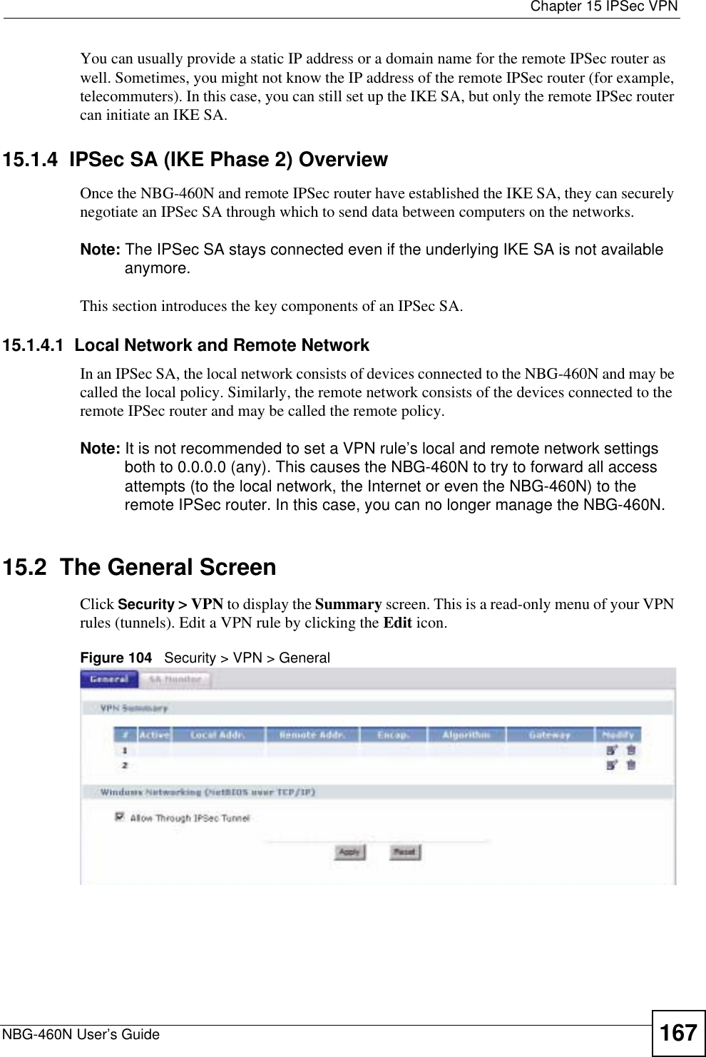
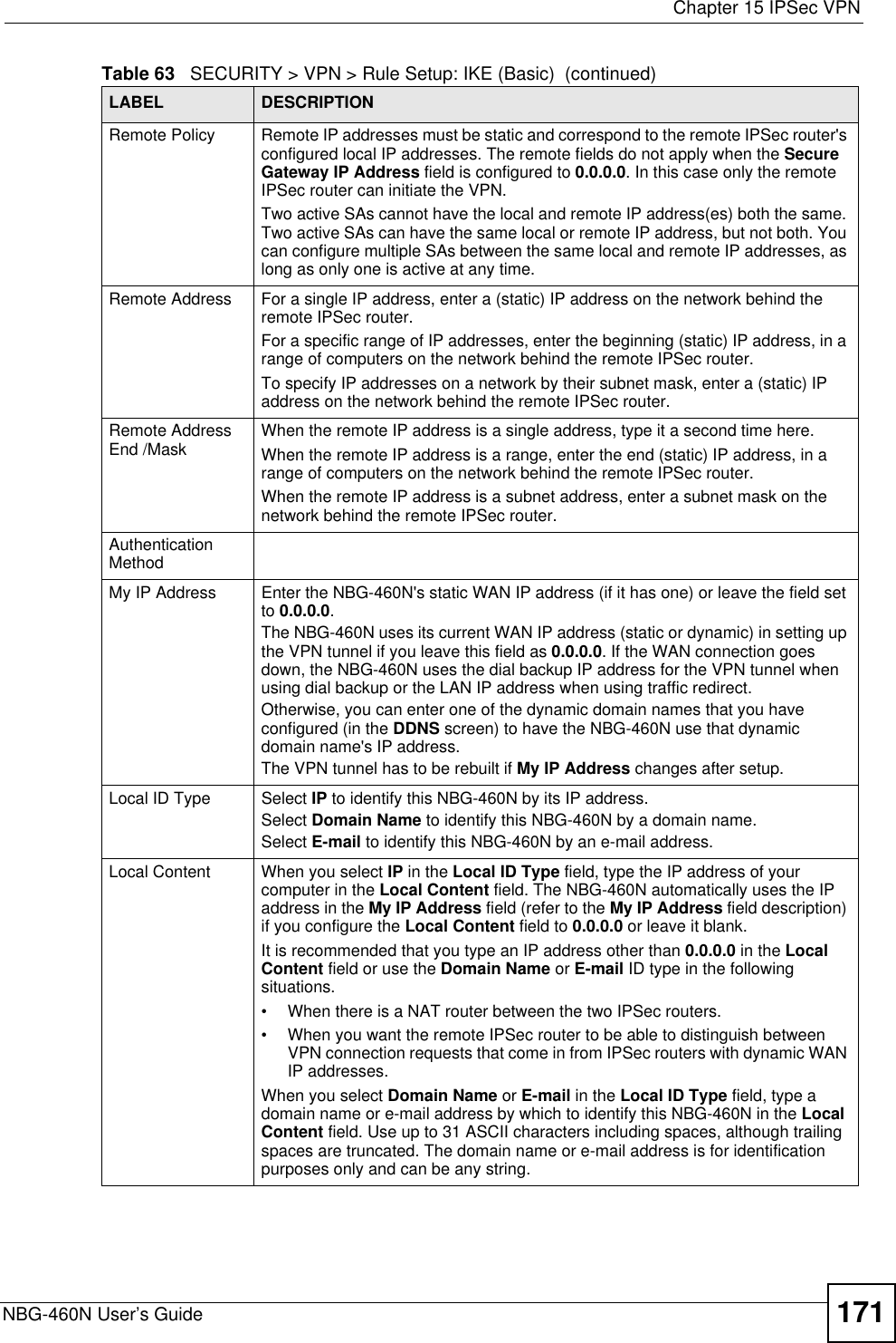
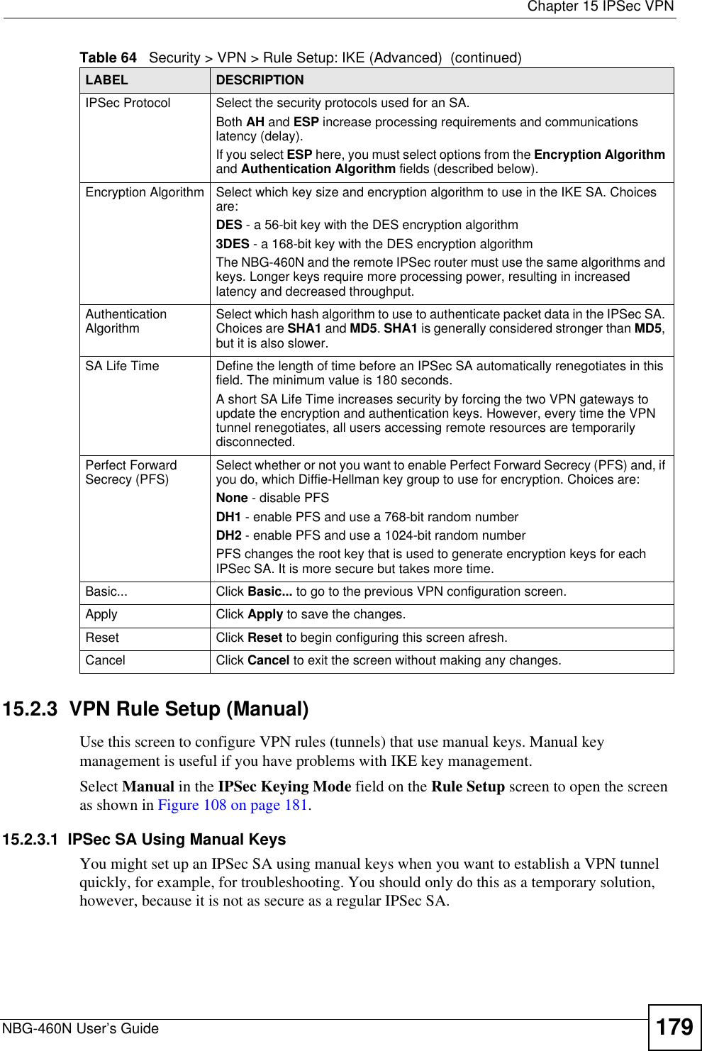
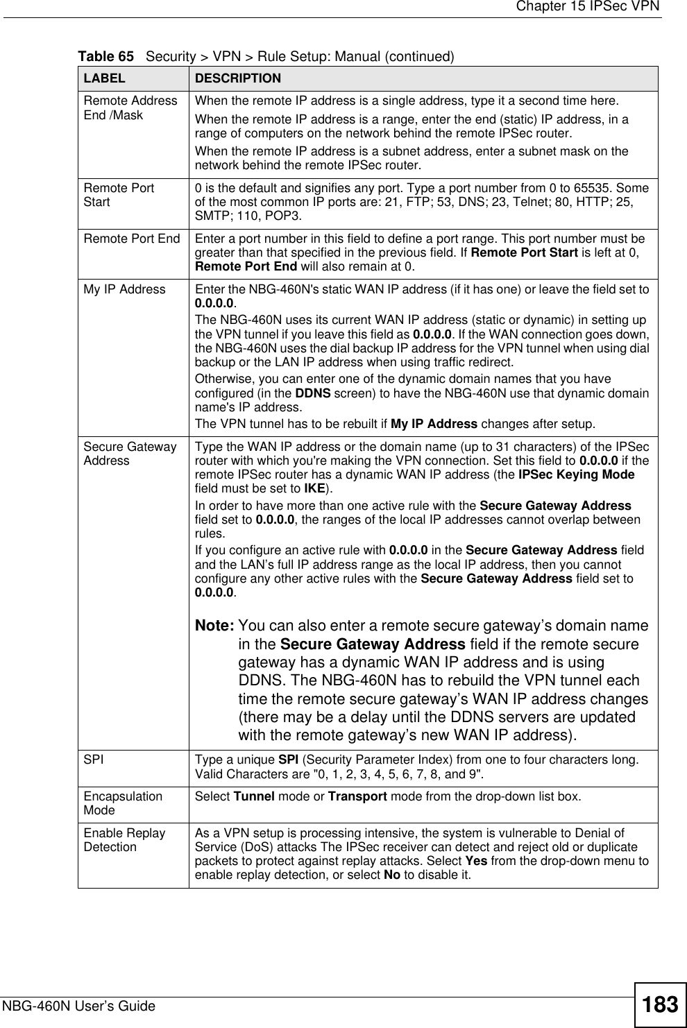
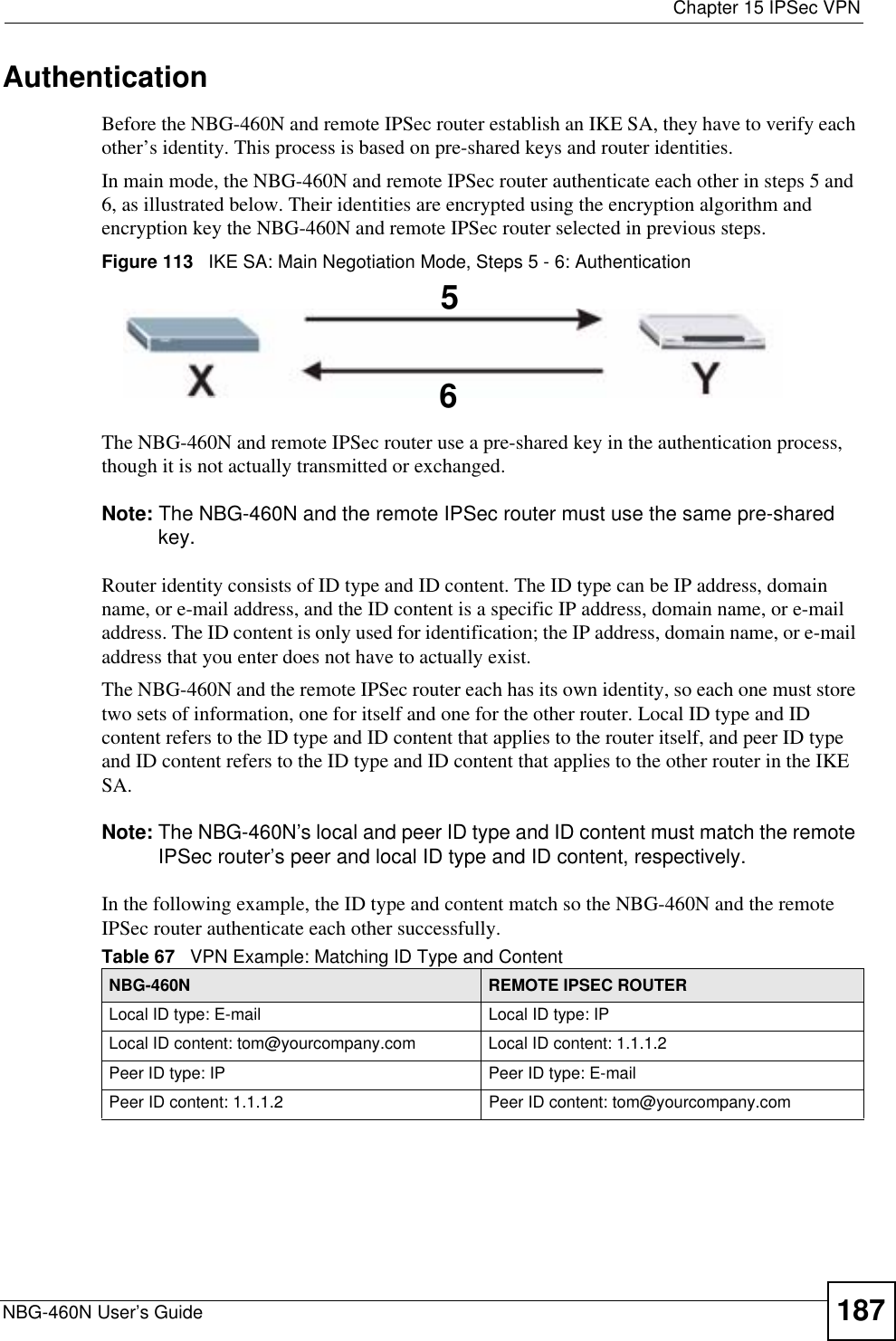
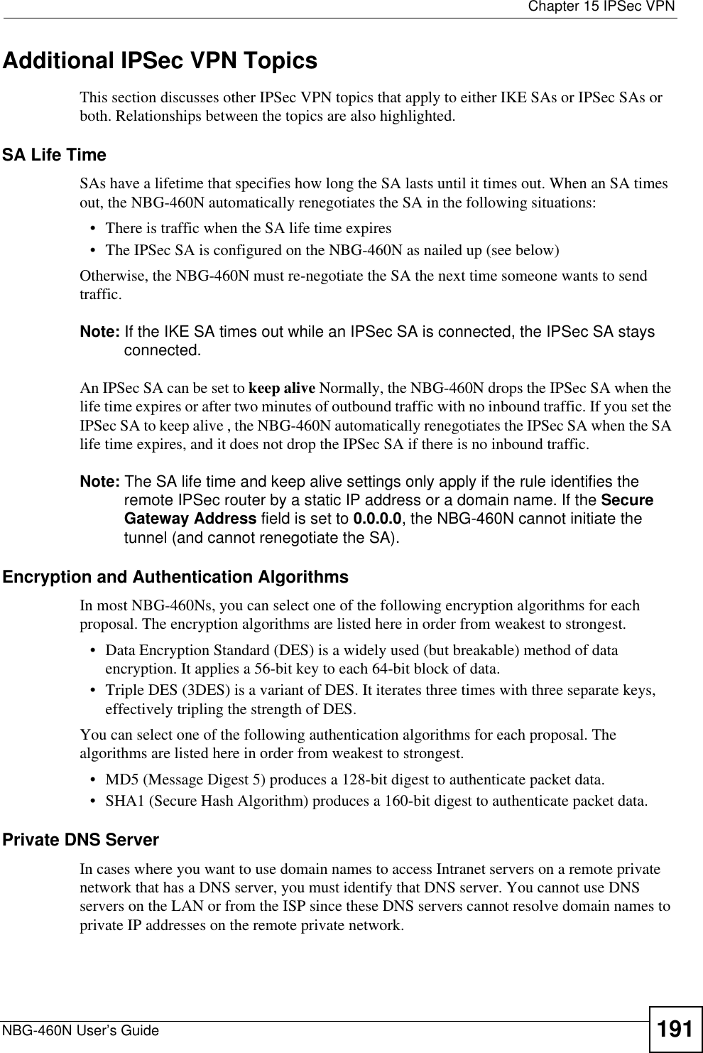
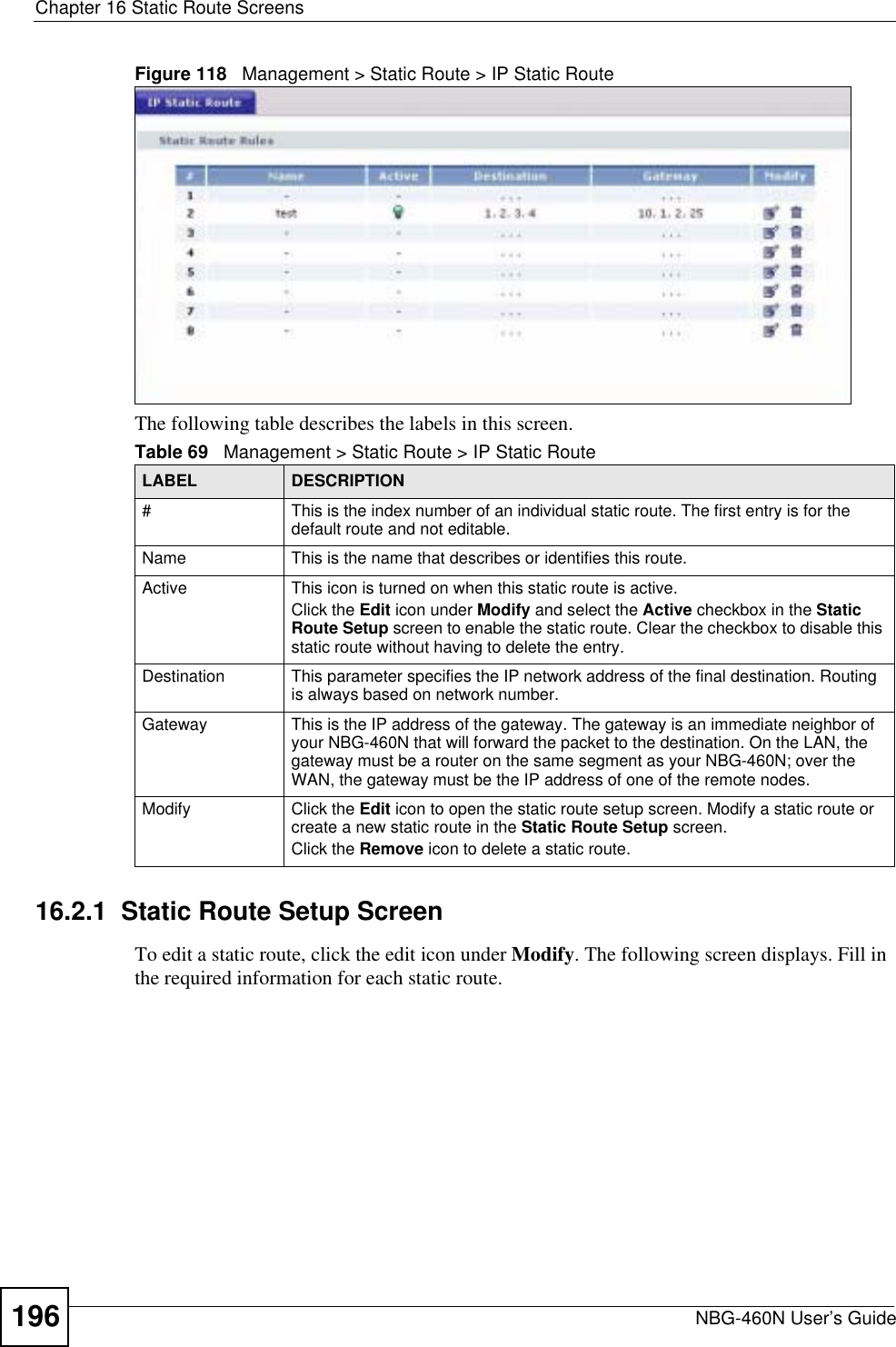
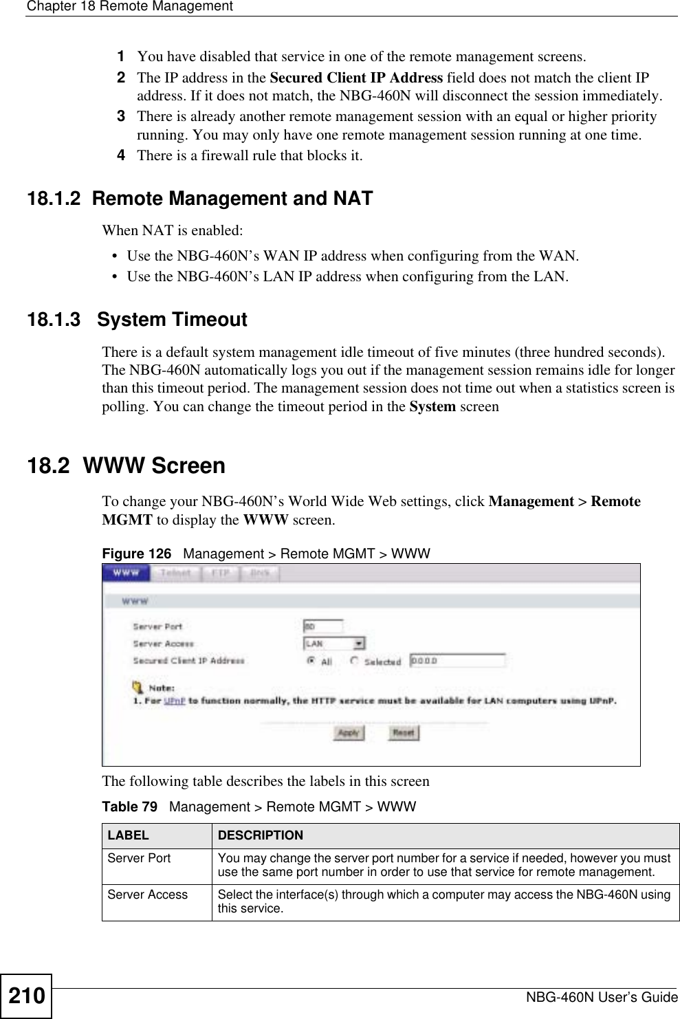
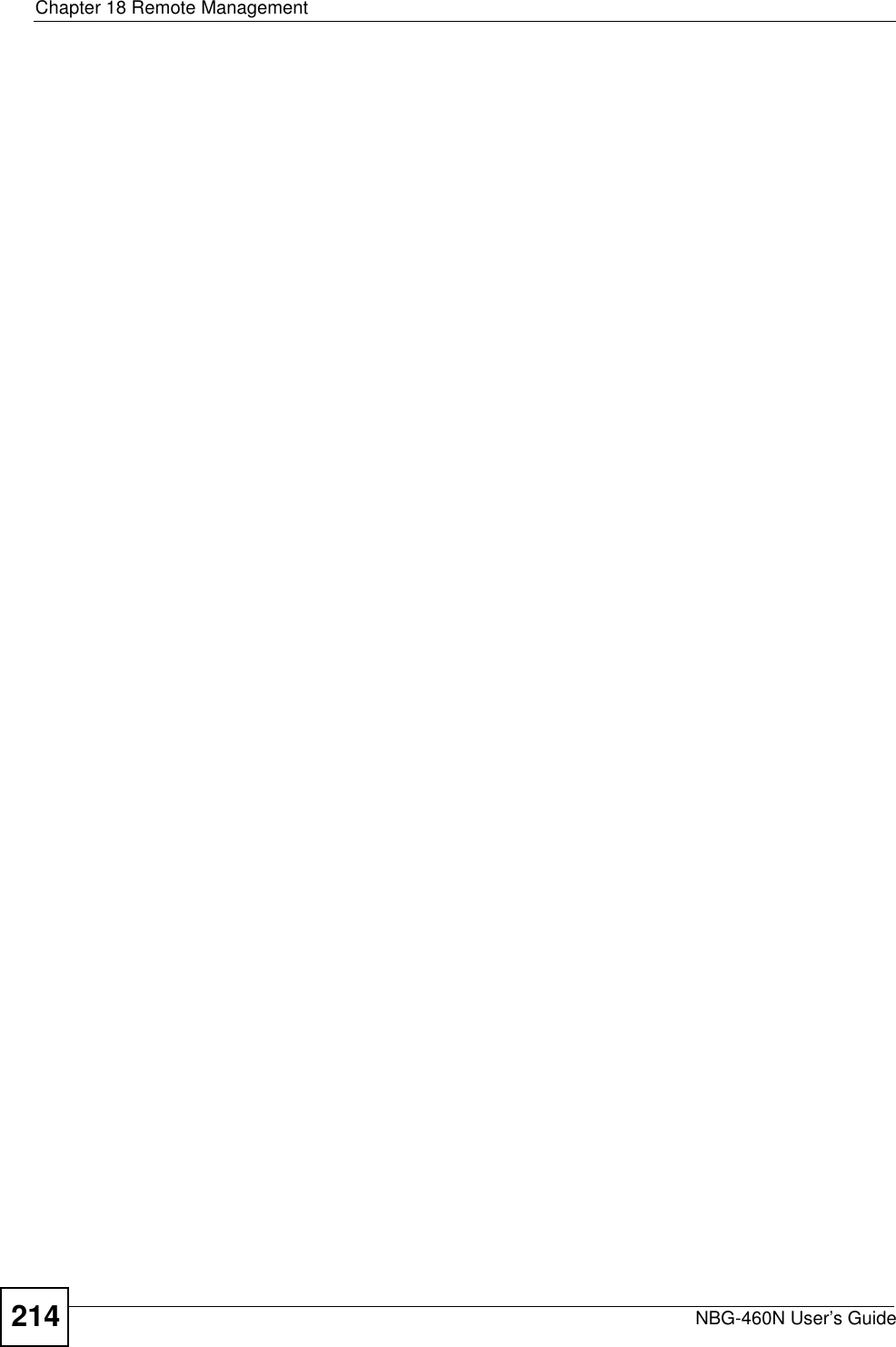
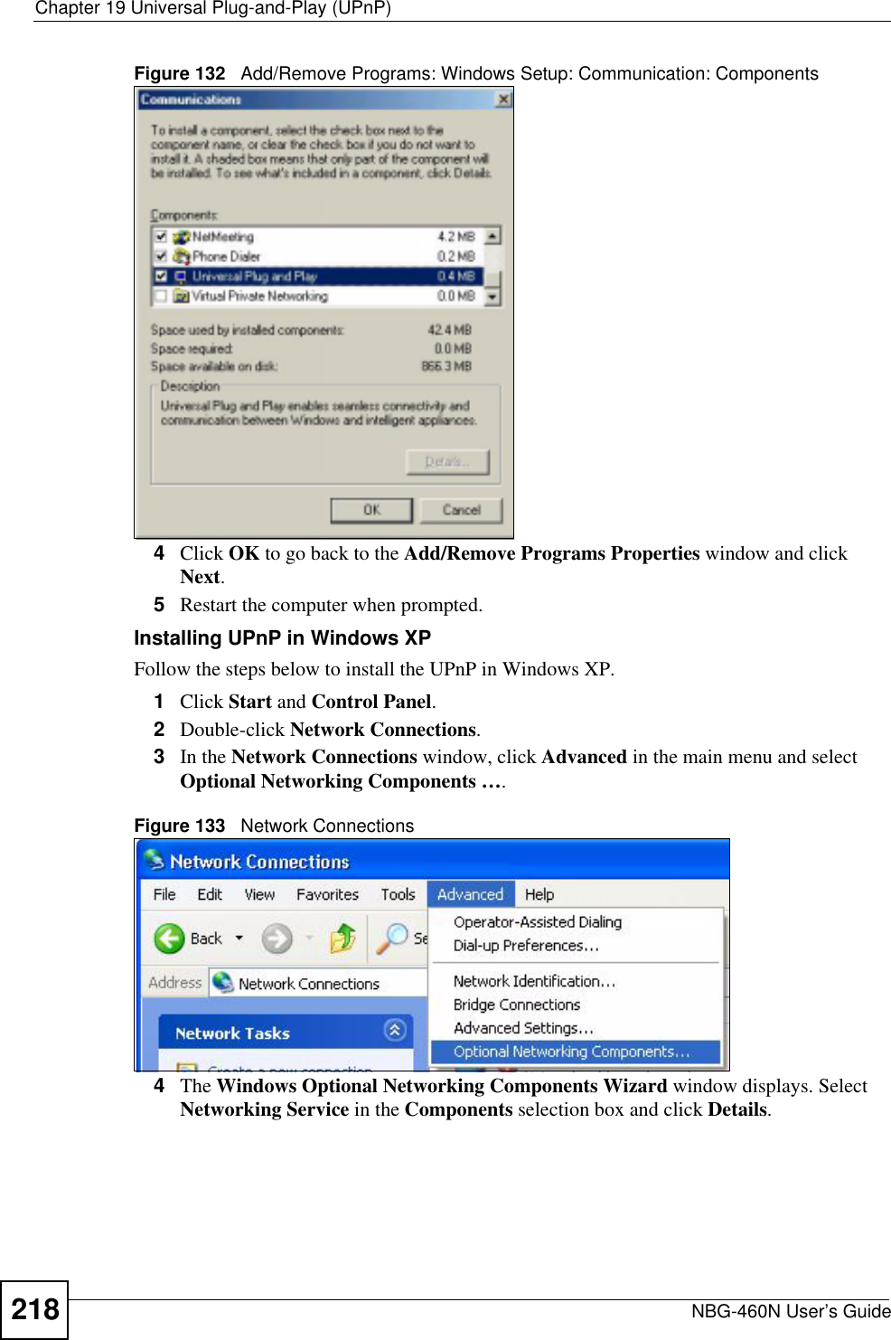
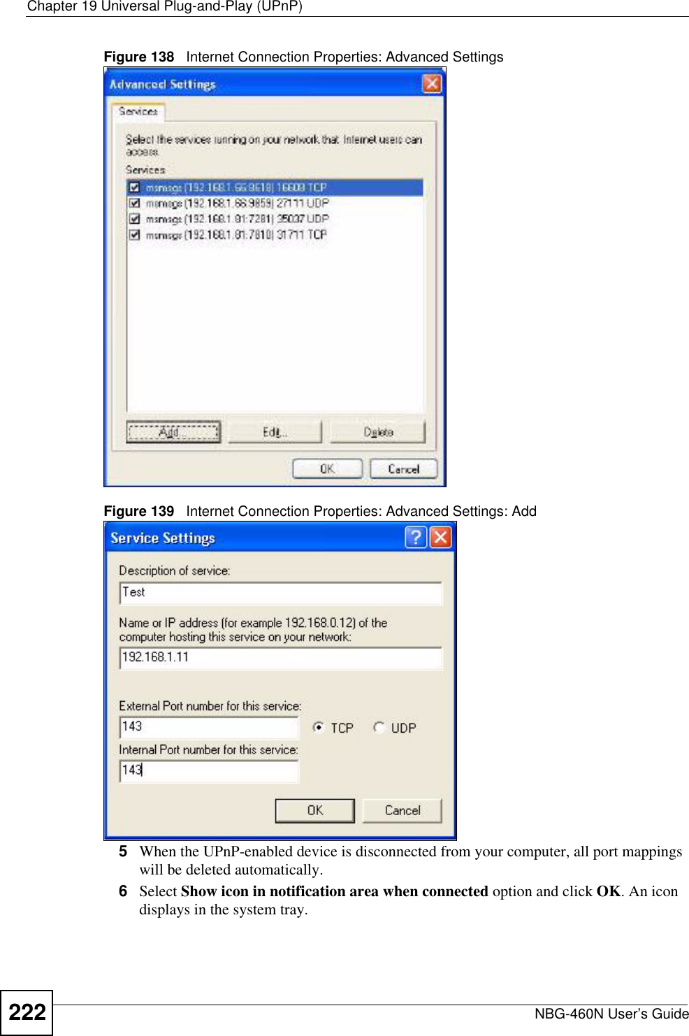
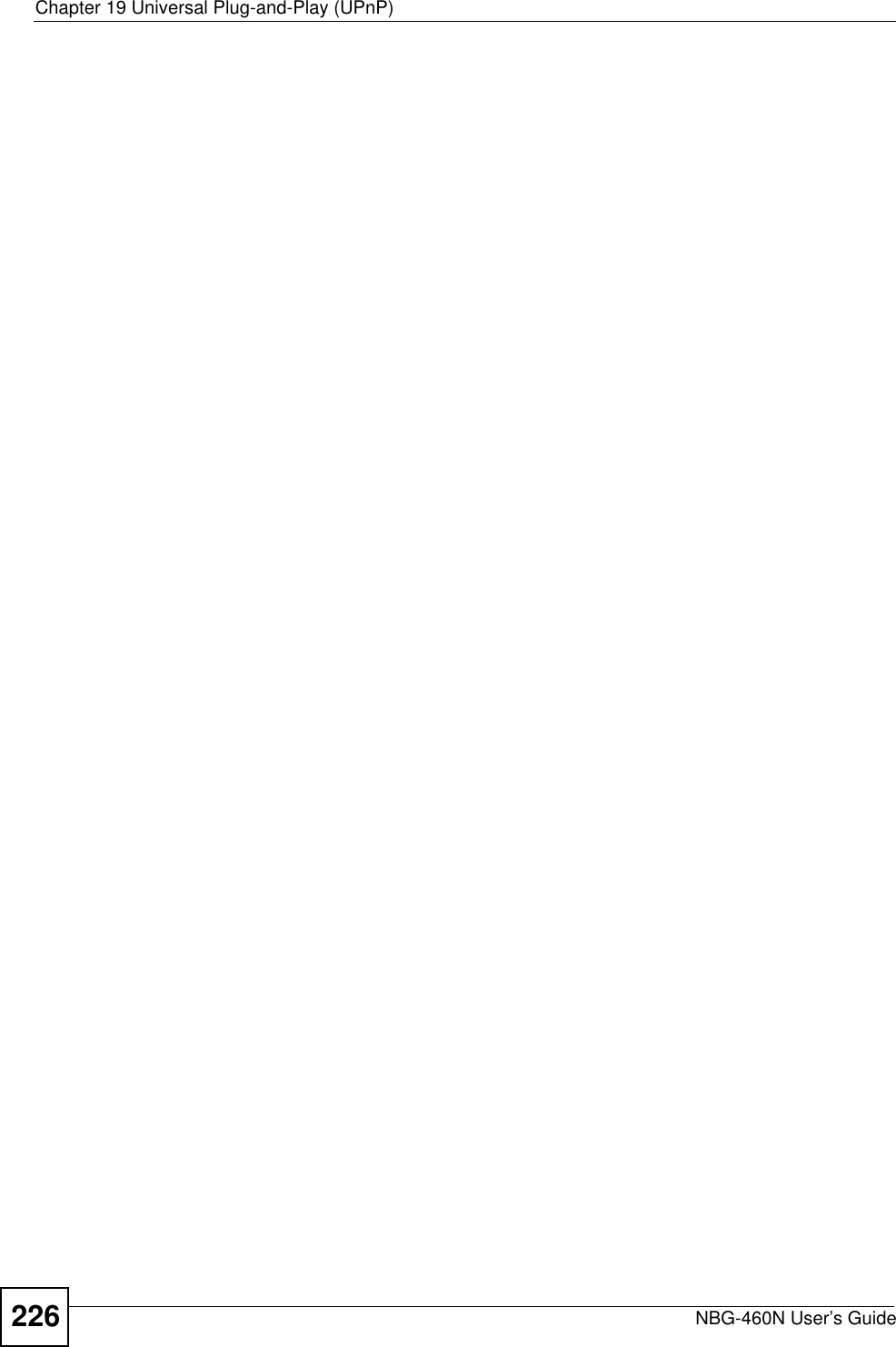
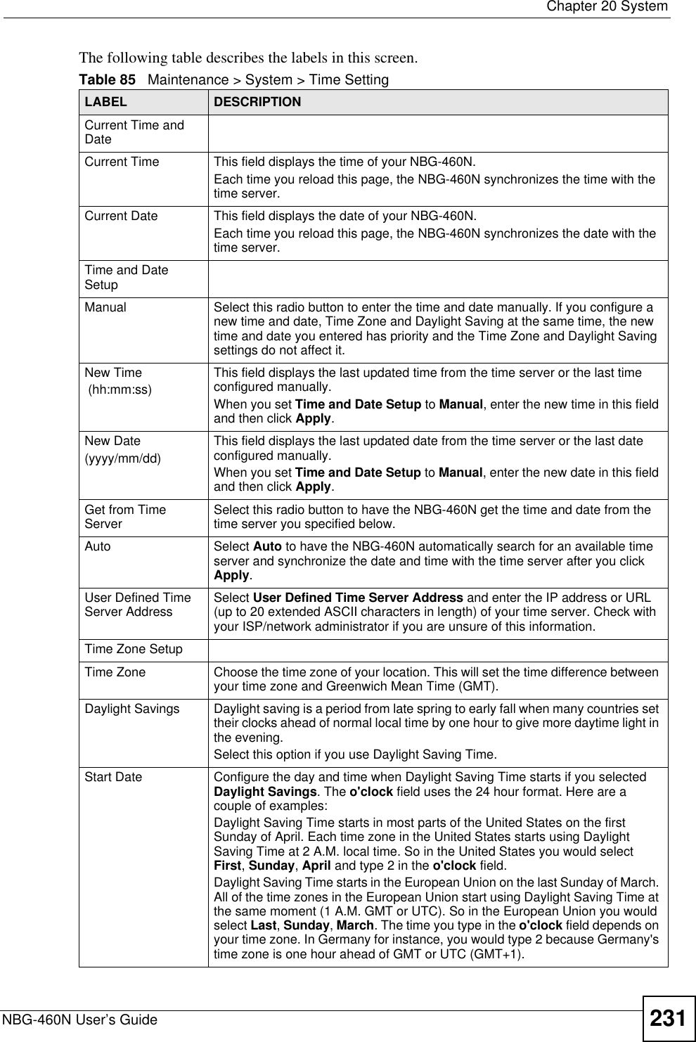
![Chapter 14 Content FilteringNBG-460N User’s Guide16414.6 Customizing Keyword Blocking URL CheckingYou can use commands to set how much of a website’s URL the content filter is to check for keyword blocking. See the appendices for information on how to access and use the command interpreter.14.6.1 Domain Name or IP Address URL CheckingBy default, the NBG-460N checks the URL’s domain name or IP address when performing keyword blocking.This means that the NBG-460N checks the characters that come before the first slash in the URL.For example, with the URL www.zyxel.com.tw/news/pressroom.php, content filtering only searches for keywords within www.zyxel.com.tw.14.6.2 Full Path URL CheckingFull path URL checking has the NBG-460N check the characters that come before the last slash in the URL.For example, with the URL www.zyxel.com.tw/news/pressroom.php, full path URL checking searches for keywords within www.zyxel.com.tw/news/.Use the ip urlfilter customize actionFlags 6 [disable | enable]command to extend (or not extend) the keyword blocking search to include the URL's full path.14.6.3 File Name URL CheckingFilename URL checking has the NBG-460N check all of the characters in the URL.For example, filename URL checking searches for keywords within the URL www.zyxel.com.tw/news/pressroom.php.Use the ip urlfilter customize actionFlags 8 [disable | enable] command to extend (or not extend) the keyword blocking search to include the URL's complete filename.Apply Click Apply to save your customized settings and exit this screen.Reset Click Reset to begin configuring this screen afreshTable 61 Security > Content Filter > ScheduleLABEL DESCRIPTION](https://usermanual.wiki/ZyXEL-Communications/X550NHV2.User-Manual-2/User-Guide-1010532-Page-14.png)
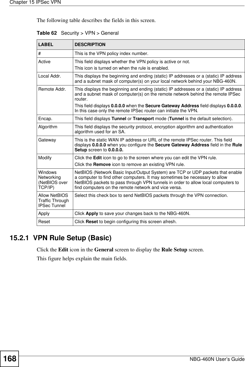
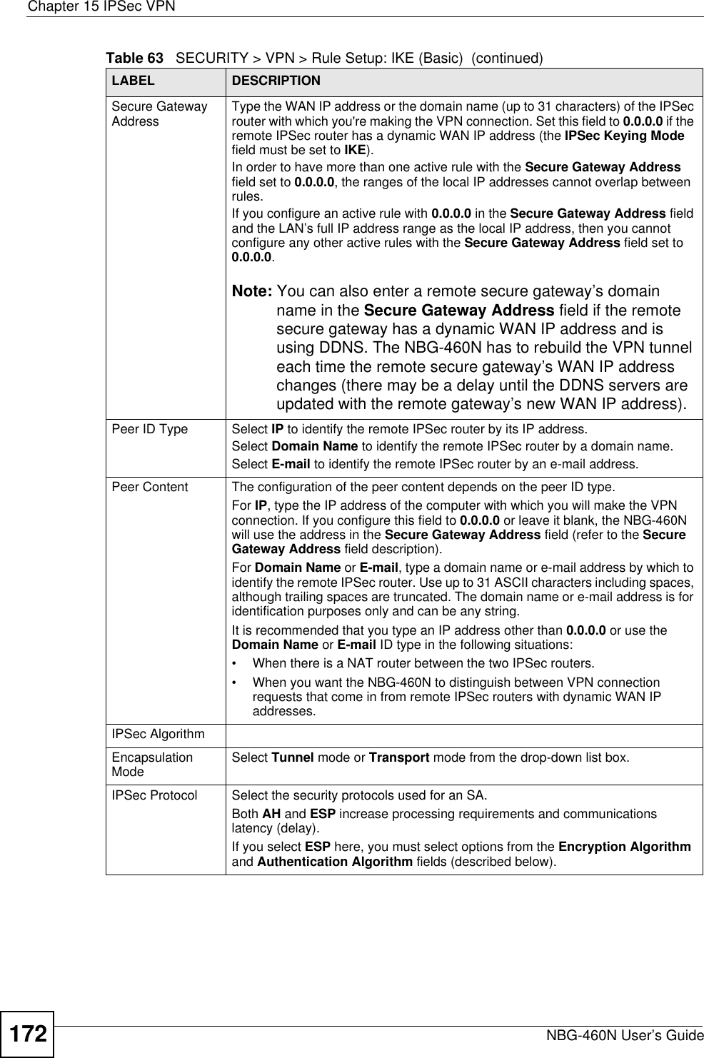
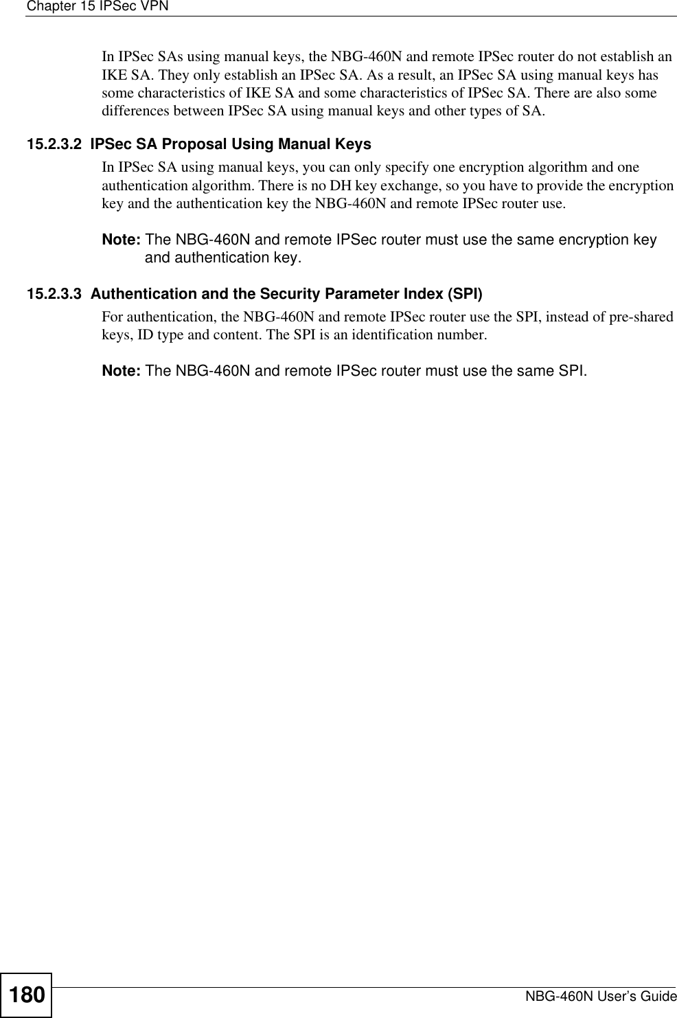
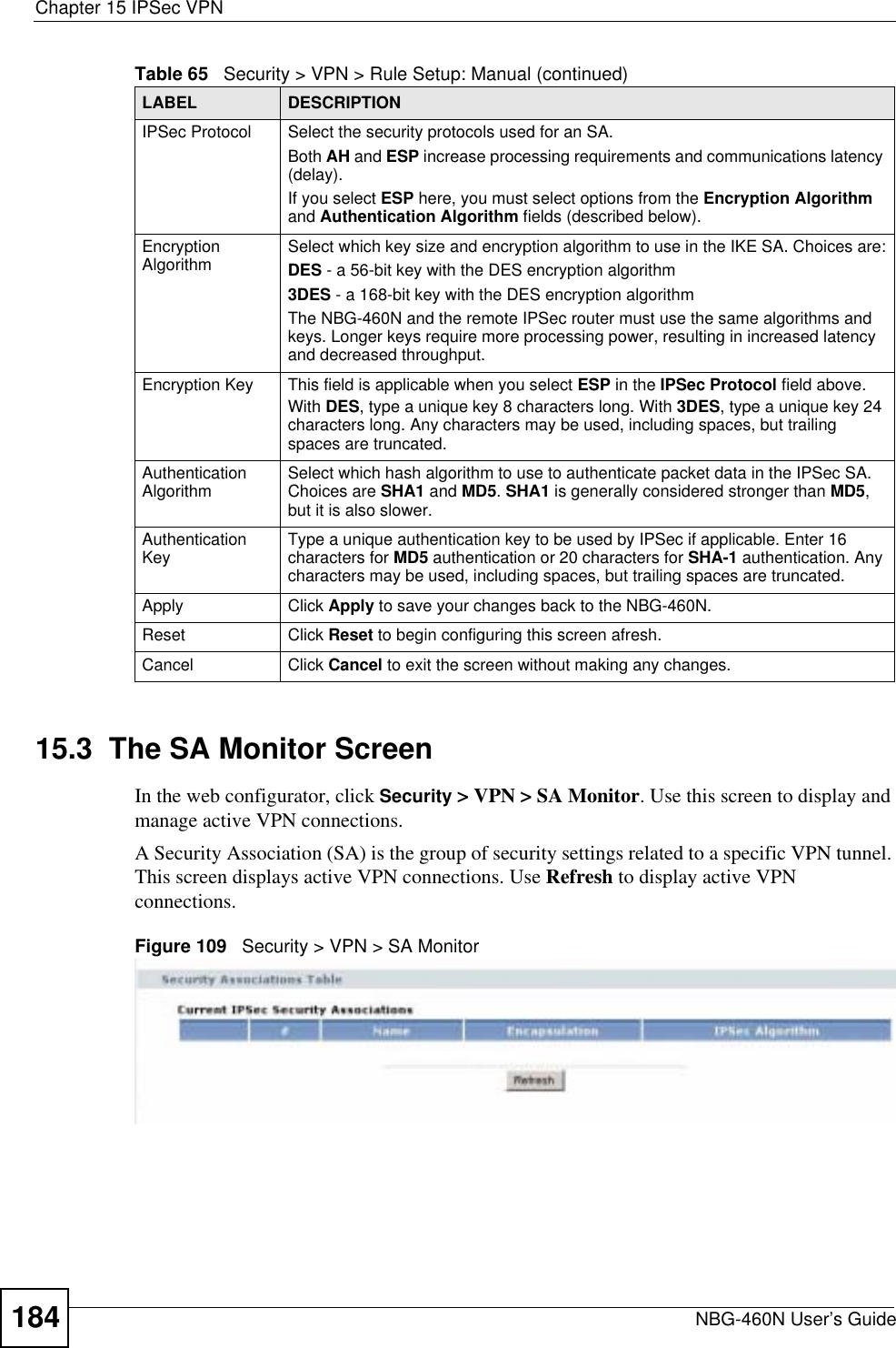
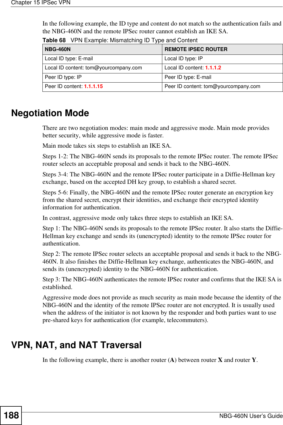
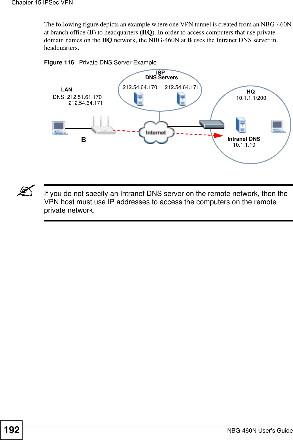

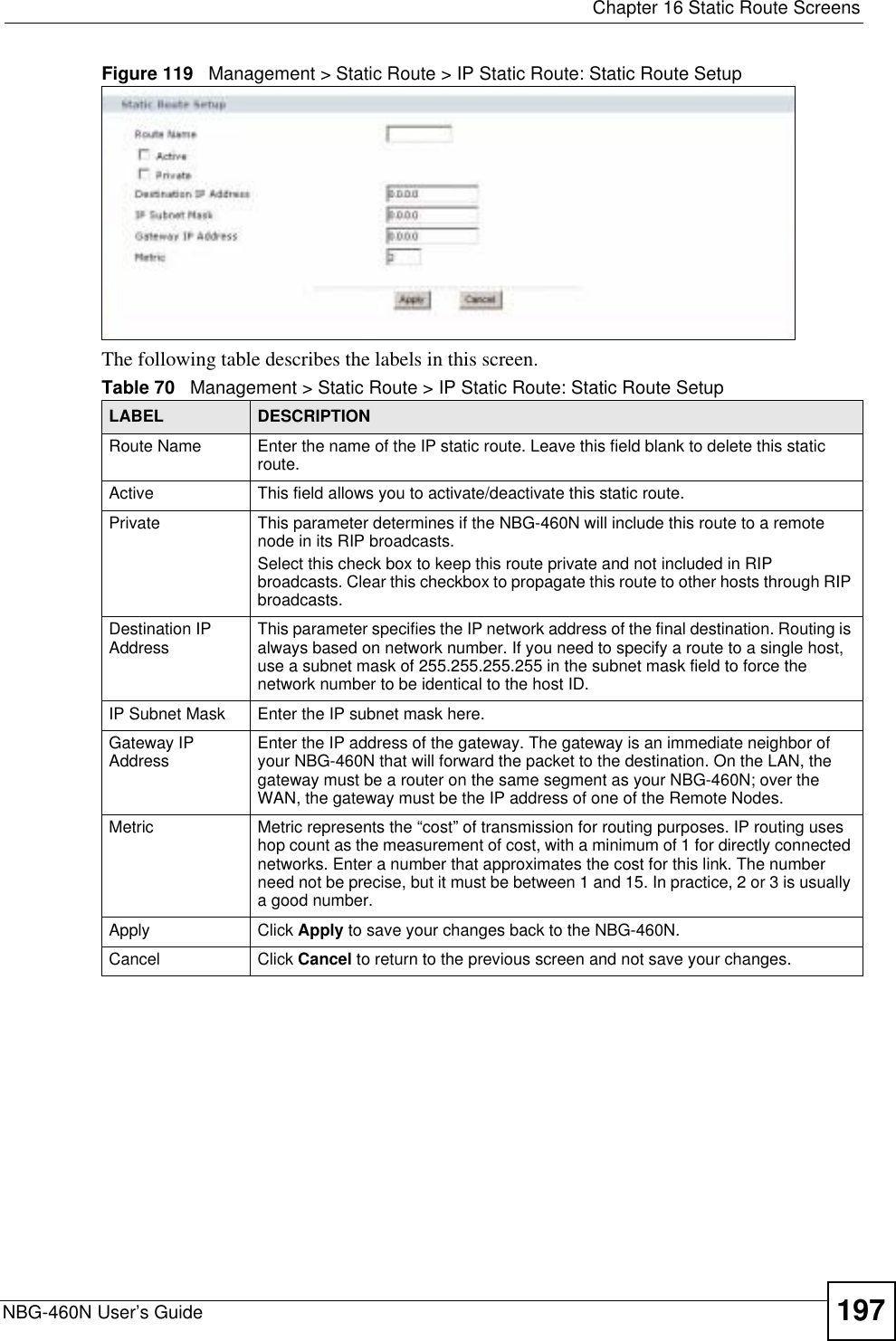

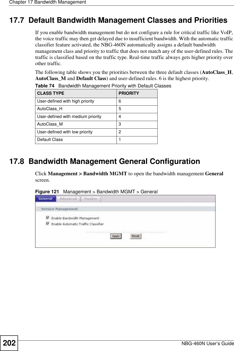

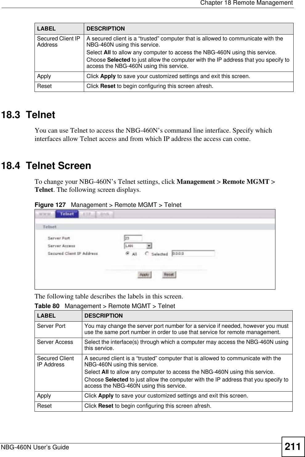
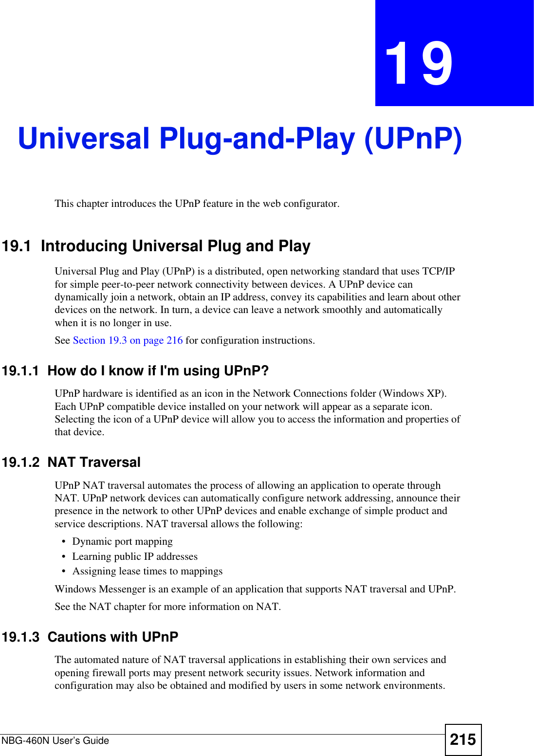
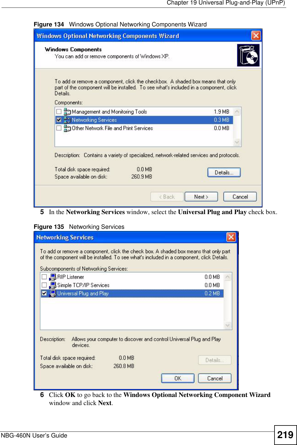
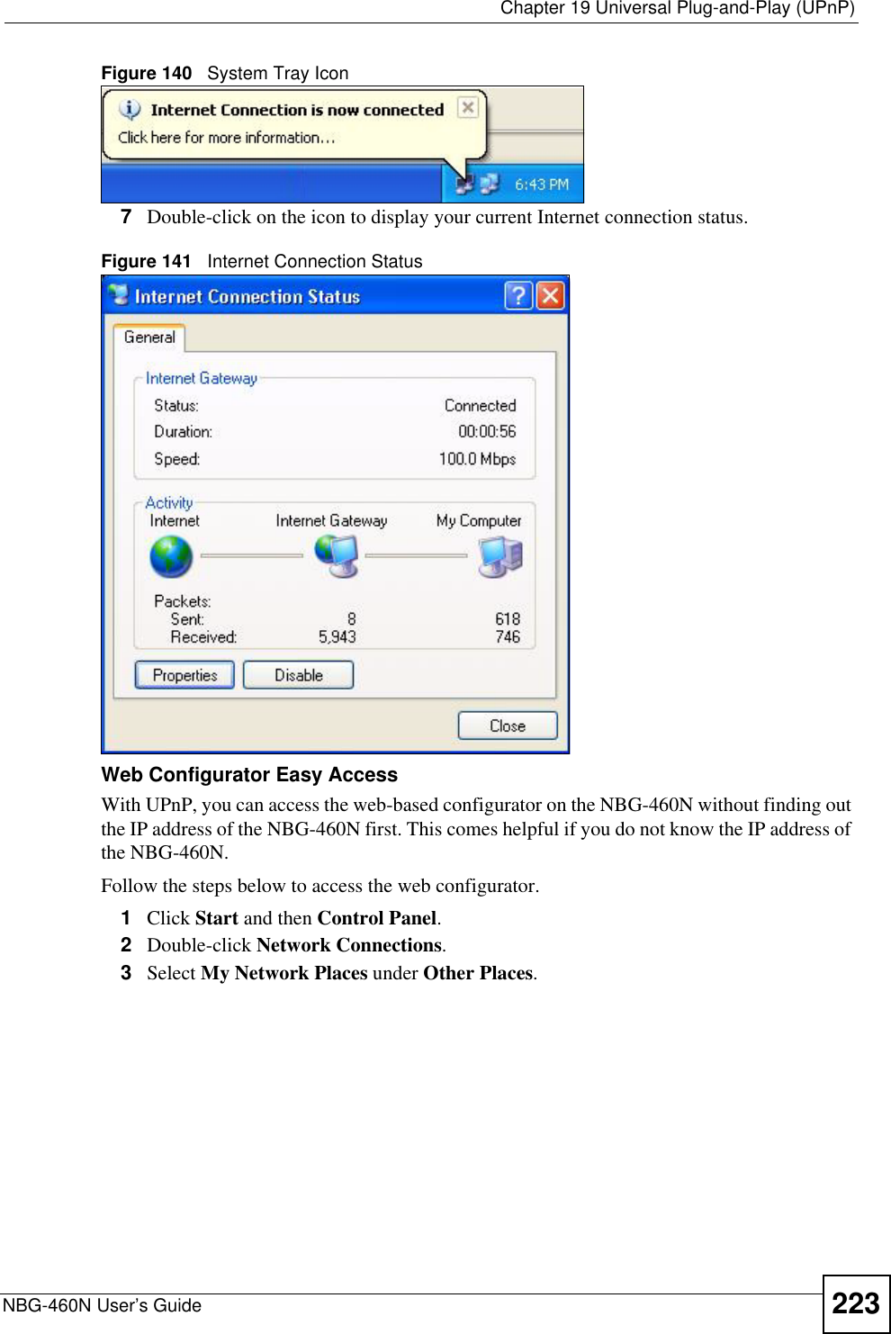
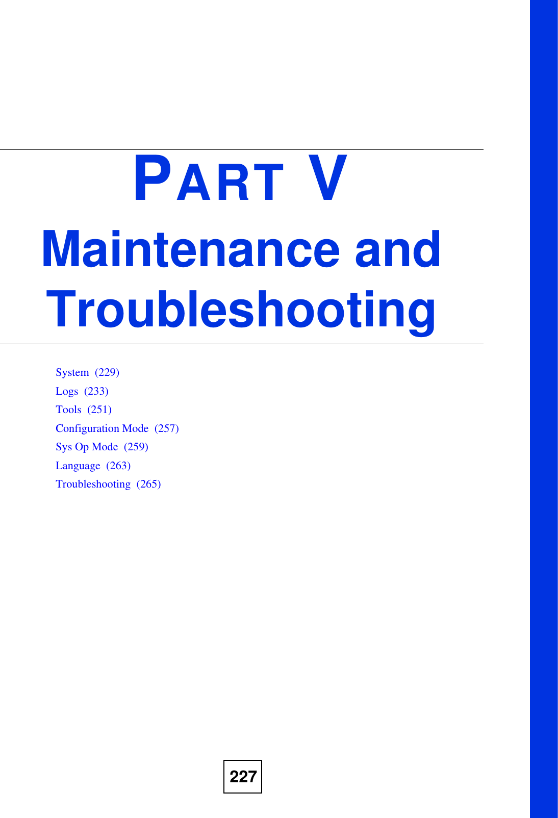

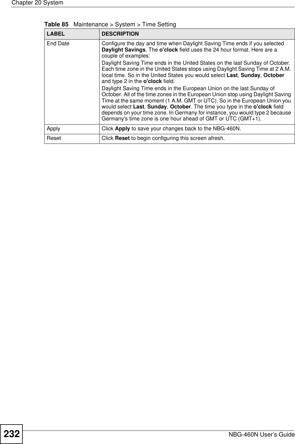
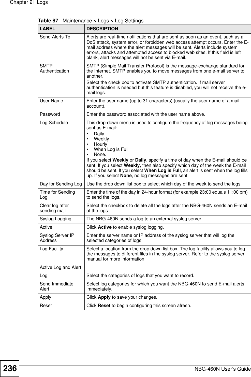
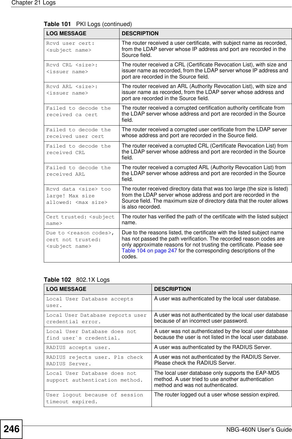
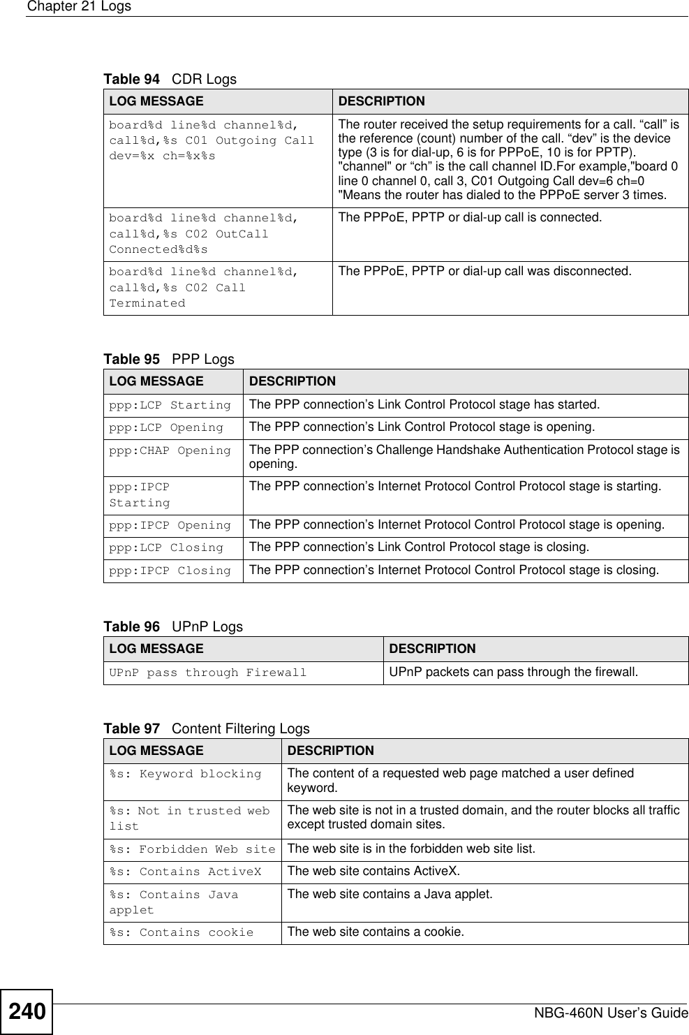
![Chapter 21 LogsNBG-460N User’s Guide238Table 89 System Error LogsLOG MESSAGE DESCRIPTION%s exceeds the max. number of session per host!This attempt to create a NAT session exceeds the maximum number of NAT session table entries allowed to be created per host.setNetBIOSFilter: calloc errorThe router failed to allocate memory for the NetBIOS filter settings.readNetBIOSFilter: calloc errorThe router failed to allocate memory for the NetBIOS filter settings.WAN connection is down. A WAN connection is down. You cannot access the network through this interface.Table 90 Access Control LogsLOG MESSAGE DESCRIPTIONFirewall default policy: [TCP | UDP | IGMP | ESP | GRE | OSPF] <Packet Direction>Attempted TCP/UDP/IGMP/ESP/GRE/OSPF access matched the default policy and was blocked or forwarded according to the default policy’s setting.Firewall rule [NOT] match:[TCP | UDP | IGMP | ESP | GRE | OSPF] <Packet Direction>, <rule:%d>Attempted TCP/UDP/IGMP/ESP/GRE/OSPF access matched (or did not match) a configured firewall rule (denoted by its number) and was blocked or forwarded according to the rule. Triangle route packet forwarded: [TCP | UDP | IGMP | ESP | GRE | OSPF]The firewall allowed a triangle route session to pass through.Packet without a NAT table entry blocked: [TCP | UDP | IGMP | ESP | GRE | OSPF]The router blocked a packet that didn't have a corresponding NAT table entry.Router sent blocked web site message: TCPThe router sent a message to notify a user that the router blocked access to a web site that the user requested.Table 91 TCP Reset LogsLOG MESSAGE DESCRIPTIONUnder SYN flood attack, sent TCP RSTThe router sent a TCP reset packet when a host was under a SYN flood attack (the TCP incomplete count is per destination host.) Exceed TCP MAX incomplete, sent TCP RSTThe router sent a TCP reset packet when the number of TCP incomplete connections exceeded the user configured threshold. (the TCP incomplete count is per destination host.) Note: Refer to TCP Maximum Incomplete in the Firewall Attack Alerts screen. Peer TCP state out of order, sent TCP RSTThe router sent a TCP reset packet when a TCP connection state was out of order.Note: The firewall refers to RFC793 Figure 6 to check the TCP state.](https://usermanual.wiki/ZyXEL-Communications/X550NHV2.User-Manual-2/User-Guide-1010532-Page-88.png)
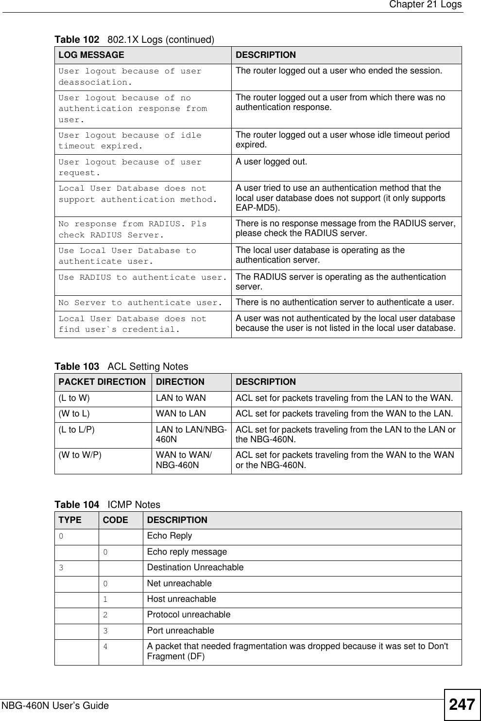
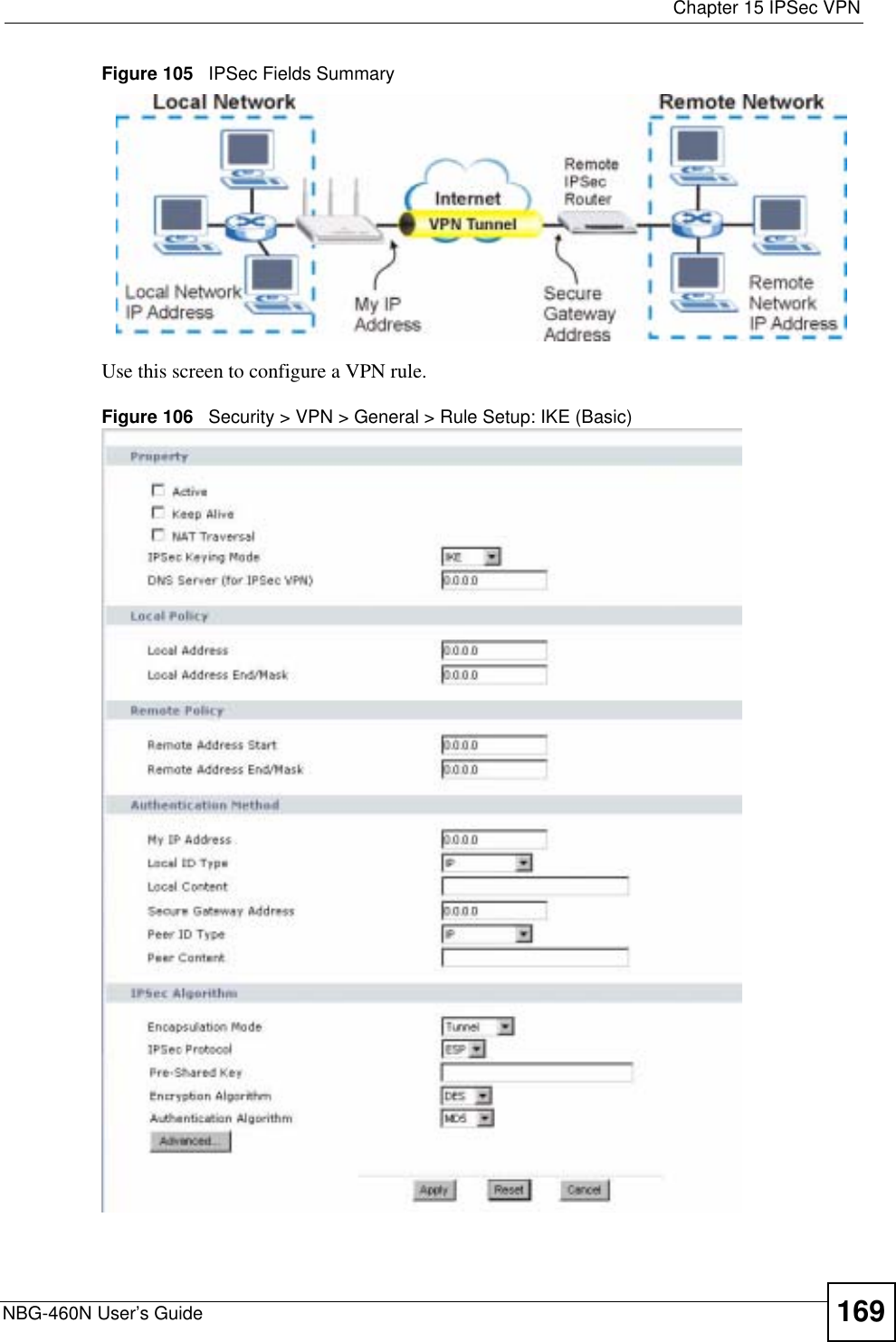
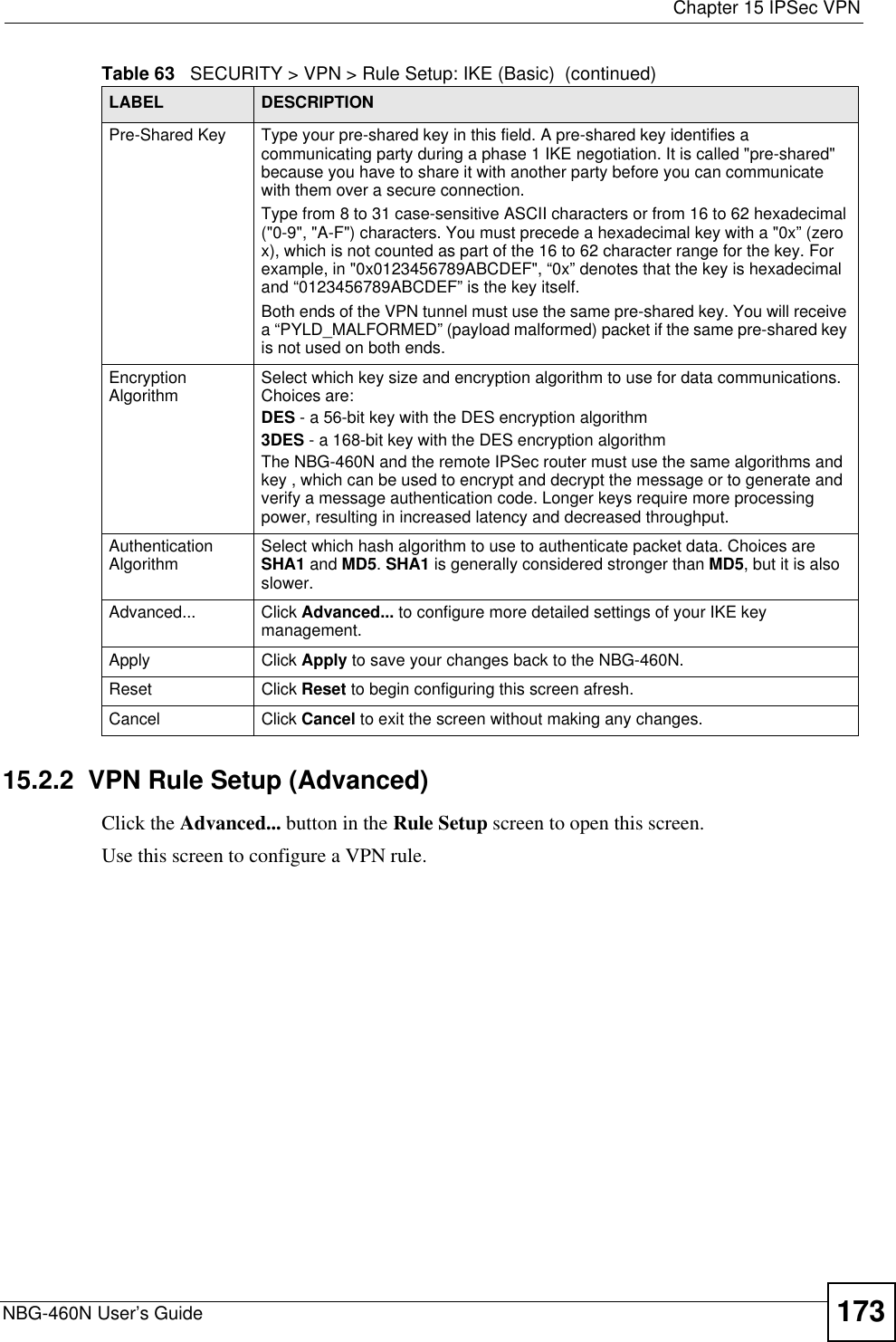
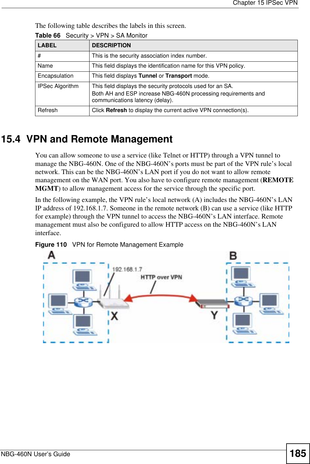
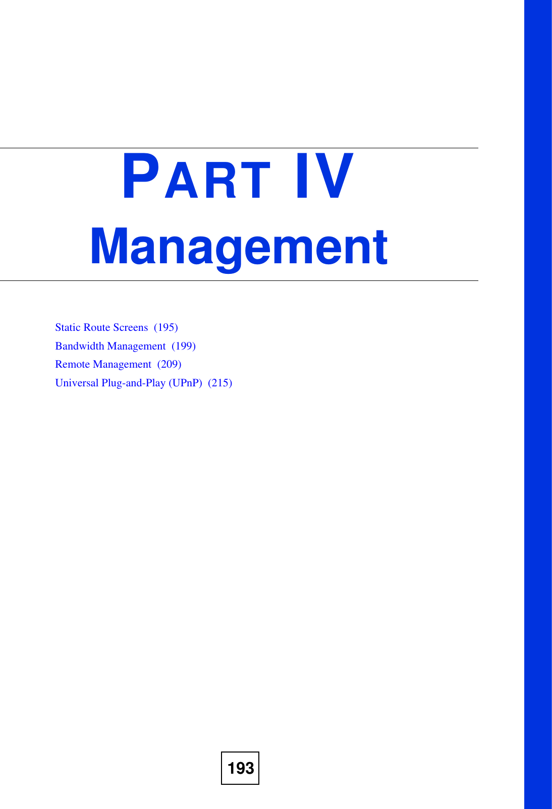
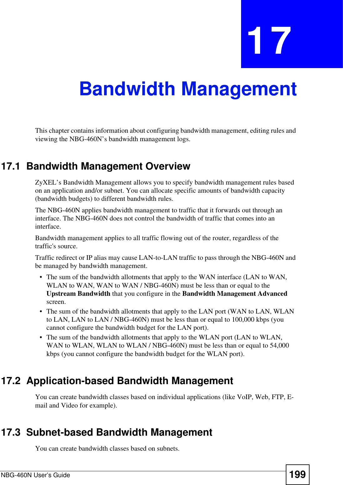
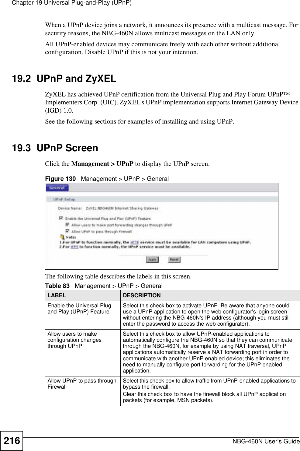
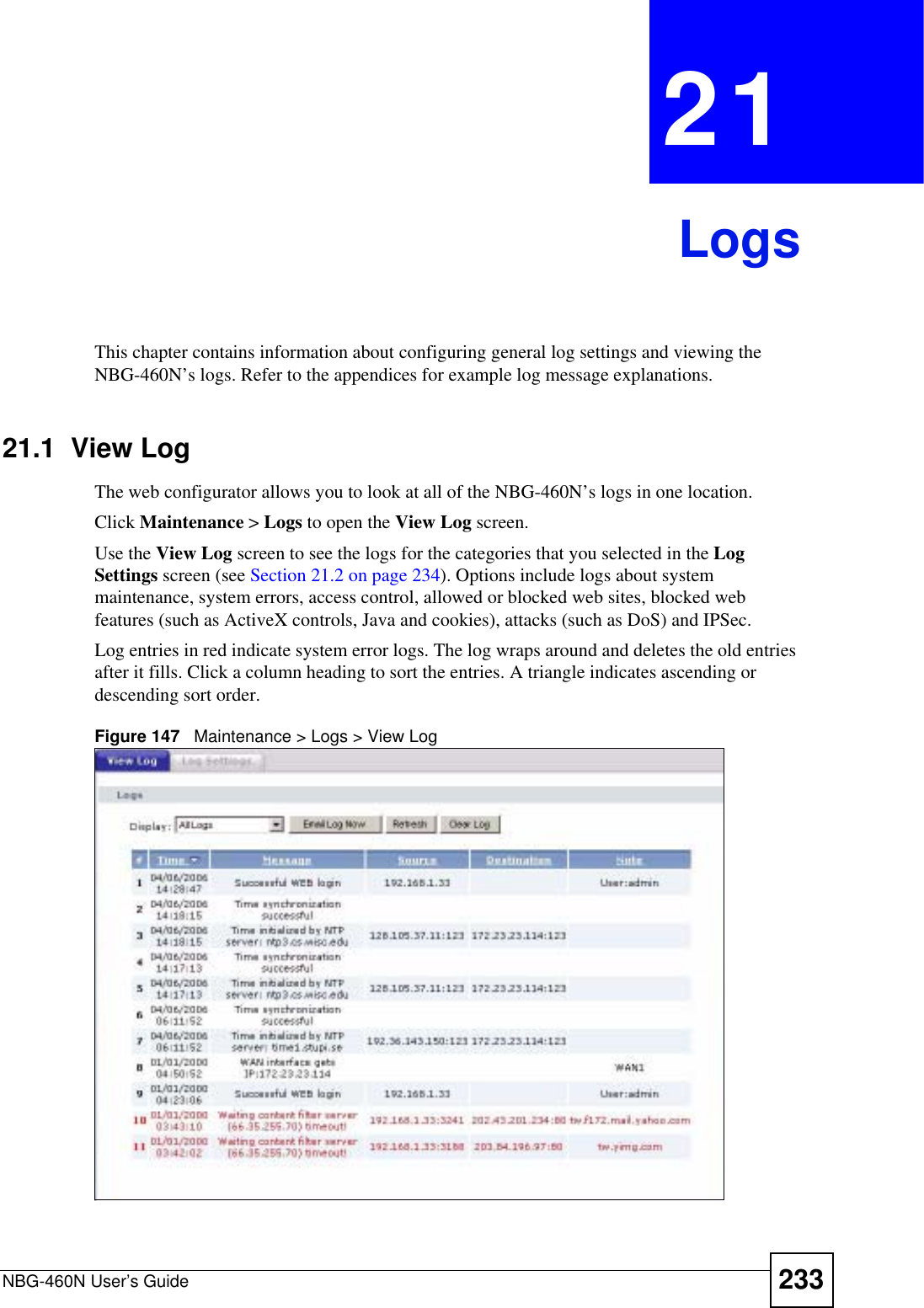
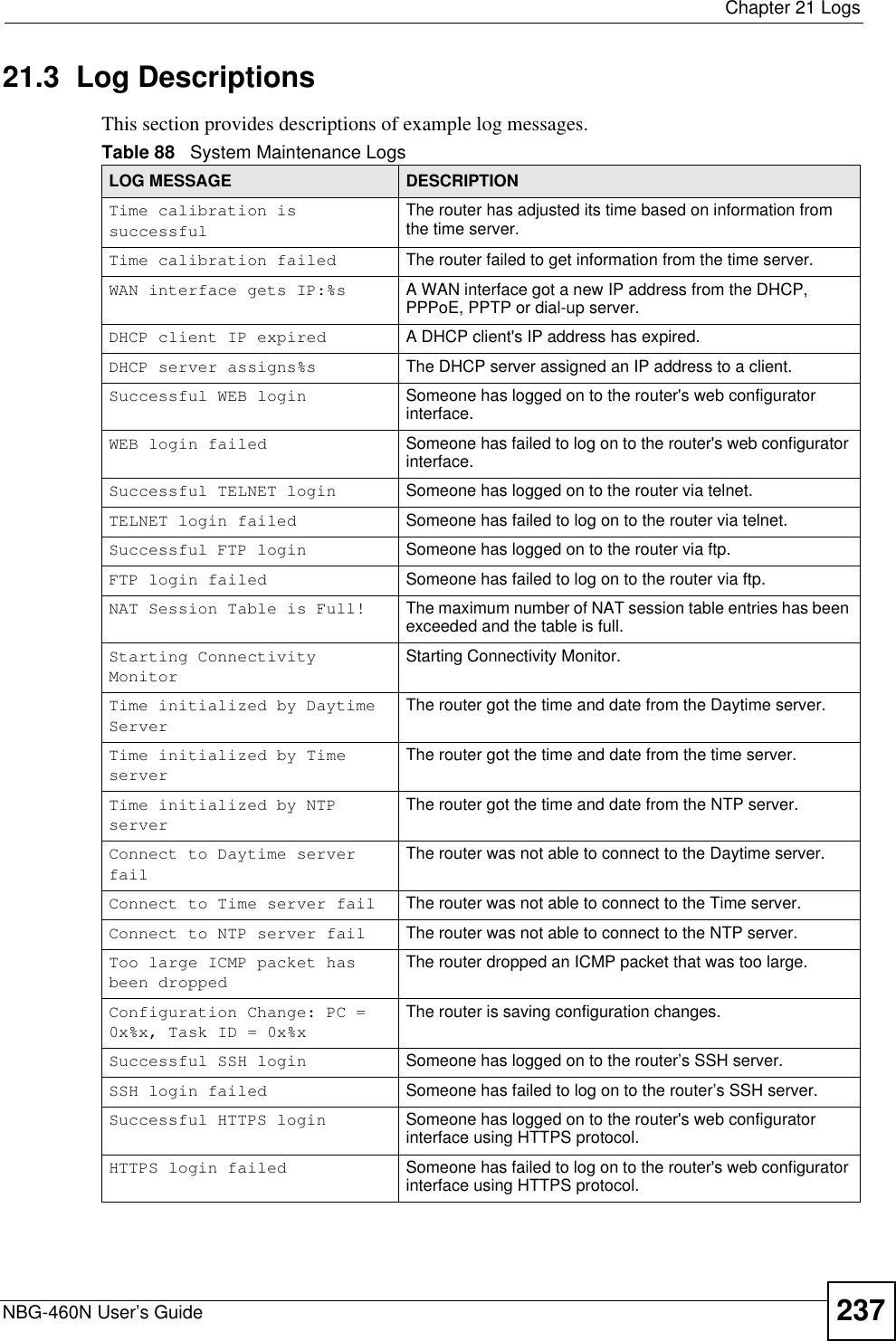
![Chapter 21 LogsNBG-460N User’s Guide 239Firewall session time out, sent TCP RSTThe router sent a TCP reset packet when a dynamic firewall session timed out.The default timeout values are as follows:ICMP idle timeout: 3 minutesUDP idle timeout: 3 minutesTCP connection (three way handshaking) timeout: 270 secondsTCP FIN-wait timeout: 2 MSL (Maximum Segment Lifetime set in the TCP header).TCP idle (established) timeout (s): 150 minutesTCP reset timeout: 10 secondsExceed MAX incomplete, sent TCP RSTThe router sent a TCP reset packet when the number of incomplete connections (TCP and UDP) exceeded the user-configured threshold. (Incomplete count is for all TCP and UDP connections through the firewall.)Note: When the number of incomplete connections (TCP + UDP) > “Maximum Incomplete High”, the router sends TCP RST packets for TCP connections and destroys TOS (firewall dynamic sessions) until incomplete connections < “Maximum Incomplete Low”.Access block, sent TCP RSTThe router sends a TCP RST packet and generates this log if you turn on the firewall TCP reset mechanism (via CI command: "sys firewall tcprst").Table 92 Packet Filter LogsLOG MESSAGE DESCRIPTION[TCP | UDP | ICMP | IGMP | Generic] packet filter matched (set:%d, rule:%d)Attempted access matched a configured filter rule (denoted by its set and rule number) and was blocked or forwarded according to the rule.Table 93 ICMP LogsLOG MESSAGE DESCRIPTIONFirewall default policy: ICMP <Packet Direction>, <type:%d>, <code:%d>ICMP access matched the default policy and was blocked or forwarded according to the user's setting. For type and code details, see Table 104 on page 247.Firewall rule [NOT] match: ICMP <Packet Direction>, <rule:%d>, <type:%d>, <code:%d>ICMP access matched (or didn’t match) a firewall rule (denoted by its number) and was blocked or forwarded according to the rule. For type and code details, see Table 104 on page 247.Triangle route packet forwarded: ICMPThe firewall allowed a triangle route session to pass through.Packet without a NAT table entry blocked: ICMPThe router blocked a packet that didn’t have a corresponding NAT table entry.Unsupported/out-of-order ICMP: ICMPThe firewall does not support this kind of ICMP packets or the ICMP packets are out of order.Router reply ICMP packet: ICMP The router sent an ICMP reply packet to the sender.Table 91 TCP Reset Logs (continued)LOG MESSAGE DESCRIPTION](https://usermanual.wiki/ZyXEL-Communications/X550NHV2.User-Manual-2/User-Guide-1010532-Page-89.png)
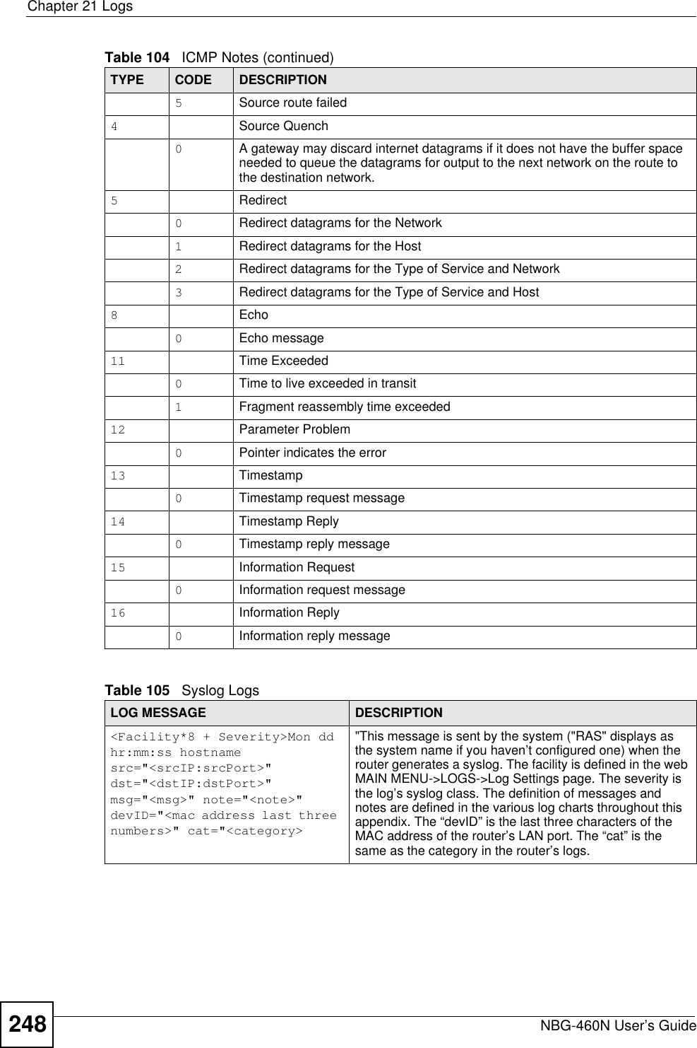
![Chapter 21 LogsNBG-460N User’s Guide 241%s: Proxy mode detectedThe router detected proxy mode in the packet.%s The content filter server responded that the web site is in the blocked category list, but it did not return the category type.%s:%s The content filter server responded that the web site is in the blocked category list, and returned the category type.%s(cache hit) The system detected that the web site is in the blocked list from the local cache, but does not know the category type.%s:%s(cache hit) The system detected that the web site is in blocked list from the local cache, and knows the category type.%s: Trusted Web site The web site is in a trusted domain.%s When the content filter is not on according to the time schedule or you didn't select the "Block Matched Web Site” check box, the system forwards the web content.Waiting content filter server timeoutThe external content filtering server did not respond within the timeout period.DNS resolving failed The NBG-460N cannot get the IP address of the external content filtering via DNS query.Creating socket failed The NBG-460N cannot issue a query because TCP/IP socket creation failed, port:port number.Connecting to content filter server failThe connection to the external content filtering server failed.License key is invalid The external content filtering license key is invalid.Table 98 Attack LogsLOG MESSAGE DESCRIPTIONattack [TCP | UDP | IGMP | ESP | GRE | OSPF]The firewall detected a TCP/UDP/IGMP/ESP/GRE/OSPF attack.attack ICMP (type:%d, code:%d)The firewall detected an ICMP attack. For type and code details, see Table 104 on page 247.land [TCP | UDP | IGMP | ESP | GRE | OSPF]The firewall detected a TCP/UDP/IGMP/ESP/GRE/OSPF land attack.land ICMP (type:%d, code:%d)The firewall detected an ICMP land attack. For type and code details, see Table 104 on page 247.ip spoofing - WAN [TCP | UDP | IGMP | ESP | GRE | OSPF]The firewall detected an IP spoofing attack on the WAN port.ip spoofing - WAN ICMP (type:%d, code:%d)The firewall detected an ICMP IP spoofing attack on the WAN port. For type and code details, see Table 104 on page 247.icmp echo: ICMP (type:%d, code:%d)The firewall detected an ICMP echo attack. For type and code details, see Table 104 on page 247.syn flood TCP The firewall detected a TCP syn flood attack.ports scan TCP The firewall detected a TCP port scan attack.teardrop TCP The firewall detected a TCP teardrop attack.Table 97 Content Filtering Logs (continued)LOG MESSAGE DESCRIPTION](https://usermanual.wiki/ZyXEL-Communications/X550NHV2.User-Manual-2/User-Guide-1010532-Page-91.png)
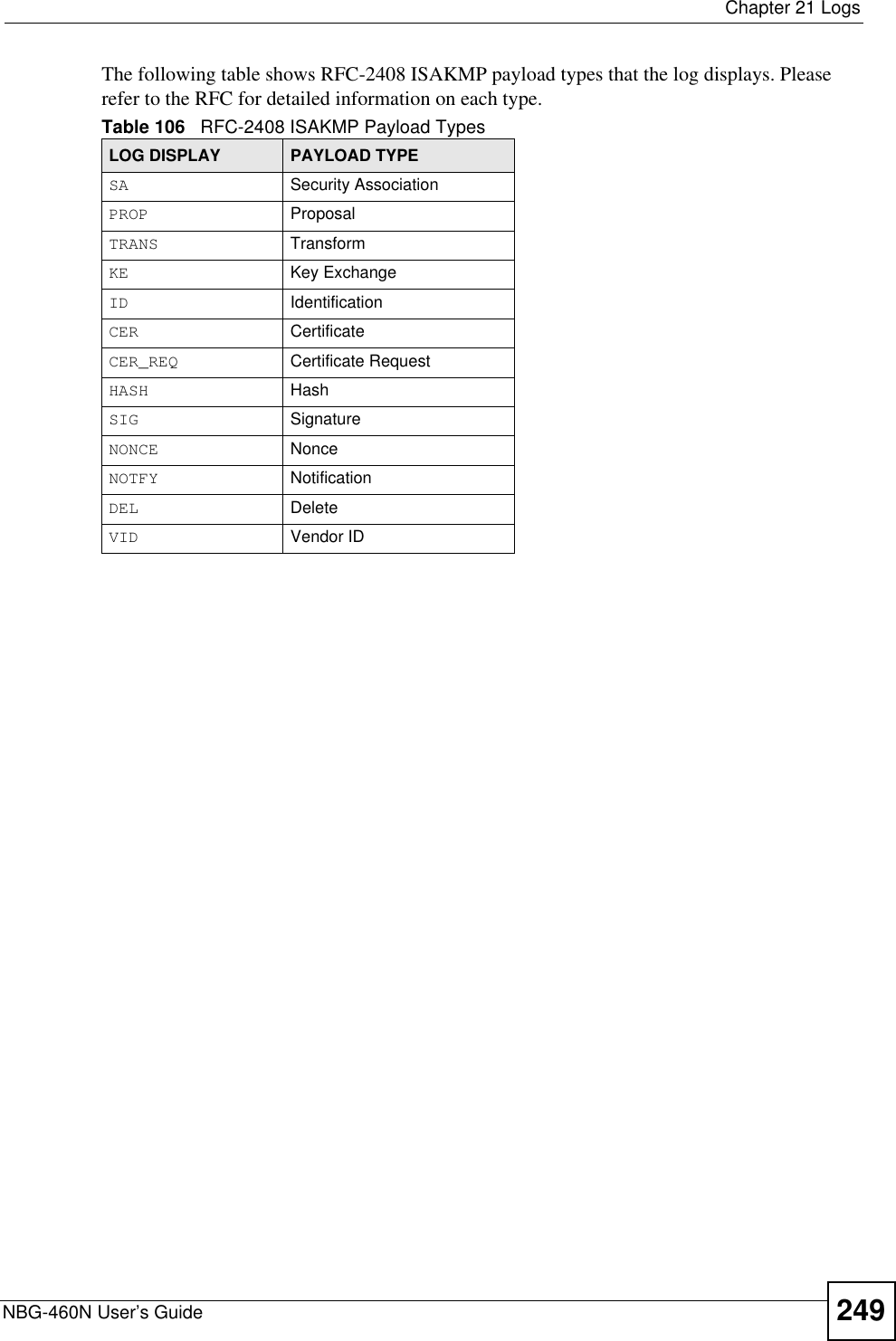
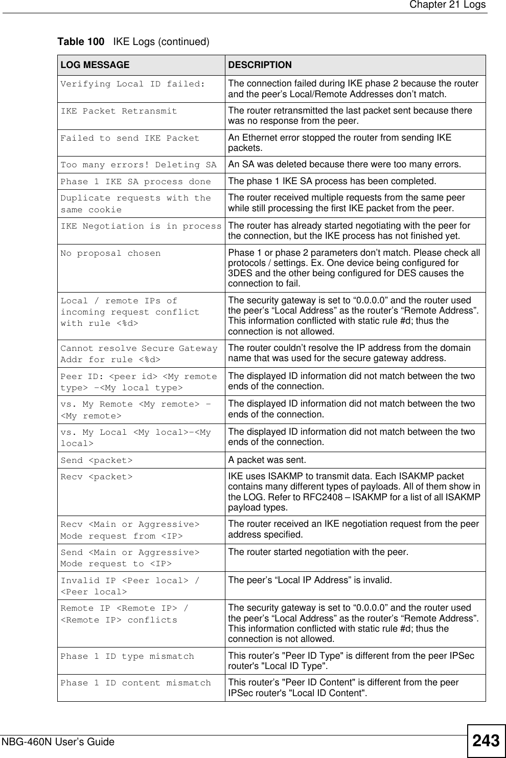
![Chapter 21 LogsNBG-460N User’s Guide242teardrop UDP The firewall detected an UDP teardrop attack.teardrop ICMP (type:%d, code:%d)The firewall detected an ICMP teardrop attack. For type and code details, see Table 104 on page 247.illegal command TCP The firewall detected a TCP illegal command attack.NetBIOS TCP The firewall detected a TCP NetBIOS attack.ip spoofing - no routing entry [TCP | UDP | IGMP | ESP | GRE | OSPF]The firewall classified a packet with no source routing entry as an IP spoofing attack.ip spoofing - no routing entry ICMP (type:%d, code:%d)The firewall classified an ICMP packet with no source routing entry as an IP spoofing attack.vulnerability ICMP (type:%d, code:%d)The firewall detected an ICMP vulnerability attack. For type and code details, see Table 104 on page 247.traceroute ICMP (type:%d, code:%d)The firewall detected an ICMP traceroute attack. For type and code details, see Table 104 on page 247.Table 99 IPSec LogsLOG MESSAGE DESCRIPTIONDiscard REPLAY packet The router received and discarded a packet with an incorrect sequence number.Inbound packet authentication failedThe router received a packet that has been altered. A third party may have altered or tampered with the packet.Receive IPSec packet, but no corresponding tunnel existsThe router dropped an inbound packet for which SPI could not find a corresponding phase 2 SA.Rule <%d> idle time out, disconnectThe router dropped a connection that had outbound traffic and no inbound traffic for a certain time period. You can use the "ipsec timer chk_conn" CI command to set the time period. The default value is 2 minutes.WAN IP changed to <IP> The router dropped all connections with the “MyIP” configured as “0.0.0.0” when the WAN IP address changed.Table 100 IKE LogsLOG MESSAGE DESCRIPTIONActive connection allowed exceededThe IKE process for a new connection failed because the limit of simultaneous phase 2 SAs has been reached.Start Phase 2: Quick Mode Phase 2 Quick Mode has started.Verifying Remote ID failed: The connection failed during IKE phase 2 because the router and the peer’s Local/Remote Addresses don’t match.Table 98 Attack Logs (continued)LOG MESSAGE DESCRIPTION](https://usermanual.wiki/ZyXEL-Communications/X550NHV2.User-Manual-2/User-Guide-1010532-Page-92.png)
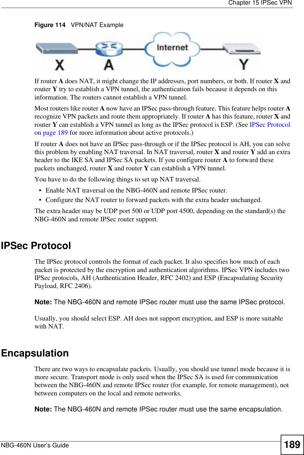
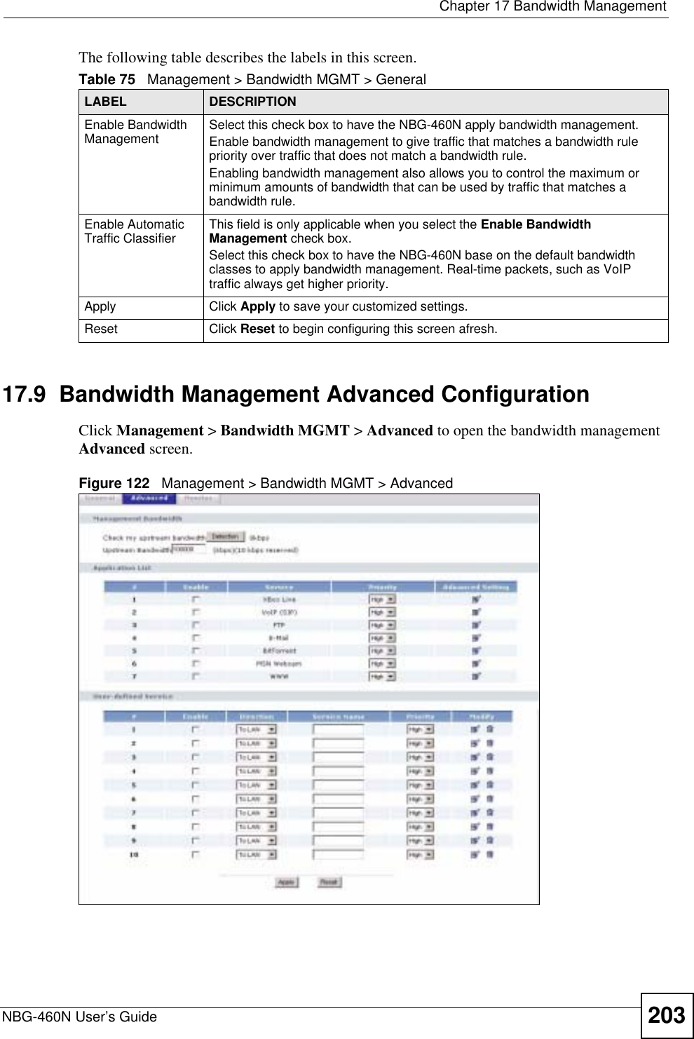
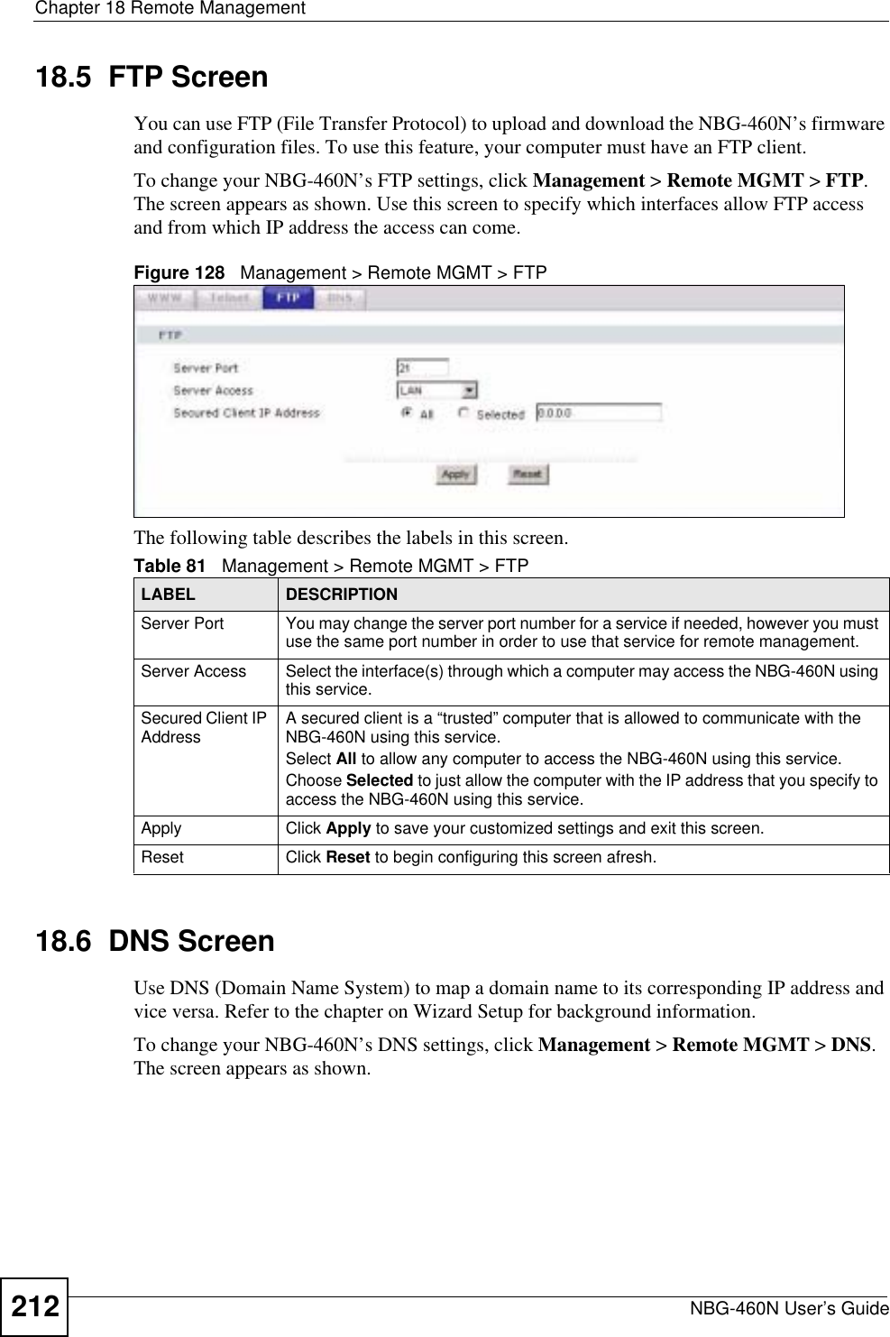
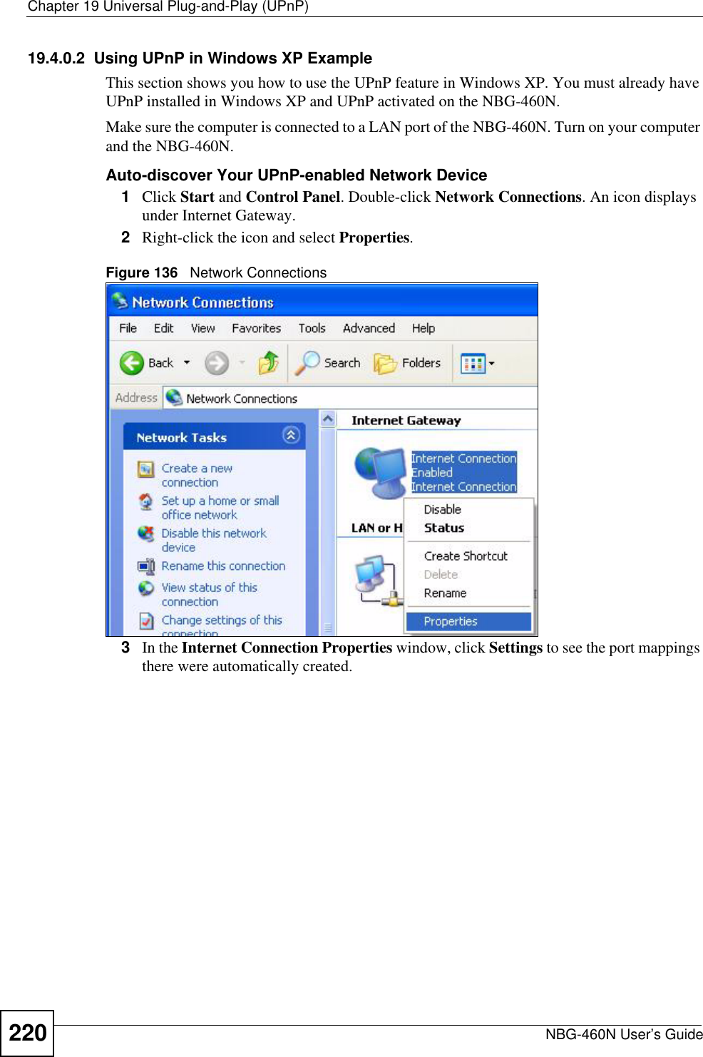
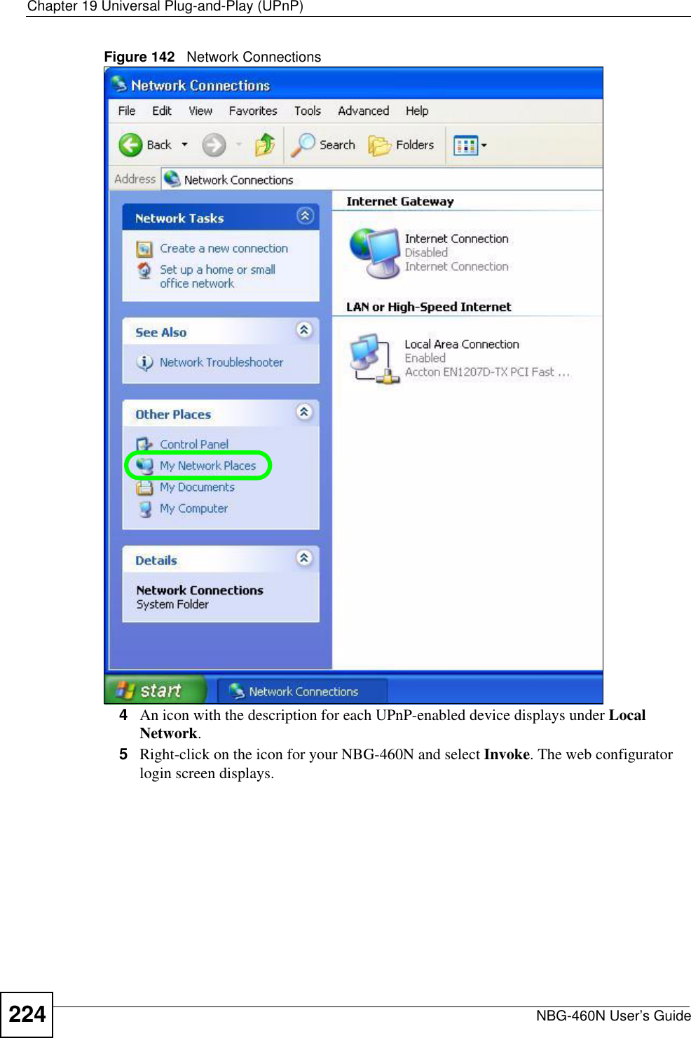
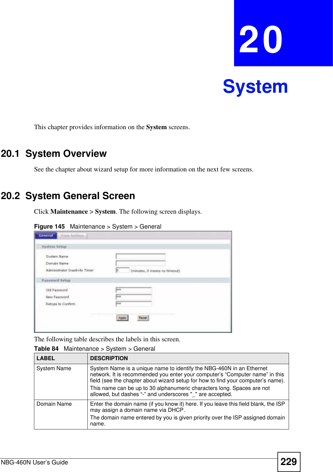
![Chapter 21 LogsNBG-460N User’s Guide244No known phase 1 ID type foundThe router could not find a known phase 1 ID in the connection attempt.ID type mismatch. Local / Peer: <Local ID type/Peer ID type>The phase 1 ID types do not match.ID content mismatch The phase 1 ID contents do not match.Configured Peer ID Content: <Configured Peer ID Content>The phase 1 ID contents do not match and the configured "Peer ID Content" is displayed.Incoming ID Content: <Incoming Peer ID Content>The phase 1 ID contents do not match and the incoming packet's ID content is displayed.Unsupported local ID Type: <%d>The phase 1 ID type is not supported by the router.Build Phase 1 ID The router has started to build the phase 1 ID.Adjust TCP MSS to%d The router automatically changed the TCP Maximum Segment Size value after establishing a tunnel.Rule <%d> input idle time out, disconnectThe tunnel for the listed rule was dropped because there was no inbound traffic within the idle timeout period.XAUTH succeed! Username: <Username>The router used extended authentication to authenticate the listed username.XAUTH fail! Username: <Username>The router was not able to use extended authentication to authenticate the listed username.Rule[%d] Phase 1 negotiation mode mismatchThe listed rule’s IKE phase 1 negotiation mode did not match between the router and the peer.Rule [%d] Phase 1 encryption algorithm mismatchThe listed rule’s IKE phase 1 encryption algorithm did not match between the router and the peer.Rule [%d] Phase 1 authentication algorithm mismatchThe listed rule’s IKE phase 1 authentication algorithm did not match between the router and the peer.Rule [%d] Phase 1 authentication method mismatchThe listed rule’s IKE phase 1 authentication method did not match between the router and the peer.Rule [%d] Phase 1 key group mismatchThe listed rule’s IKE phase 1 key group did not match between the router and the peer.Rule [%d] Phase 2 protocol mismatchThe listed rule’s IKE phase 2 protocol did not match between the router and the peer.Rule [%d] Phase 2 encryption algorithm mismatchThe listed rule’s IKE phase 2 encryption algorithm did not match between the router and the peer.Rule [%d] Phase 2 authentication algorithm mismatchThe listed rule’s IKE phase 2 authentication algorithm did not match between the router and the peer.Rule [%d] Phase 2 encapsulation mismatchThe listed rule’s IKE phase 2 encapsulation did not match between the router and the peer.Rule [%d]> Phase 2 pfs mismatchThe listed rule’s IKE phase 2 perfect forward secret (pfs) setting did not match between the router and the peer.Table 100 IKE Logs (continued)LOG MESSAGE DESCRIPTION](https://usermanual.wiki/ZyXEL-Communications/X550NHV2.User-Manual-2/User-Guide-1010532-Page-94.png)
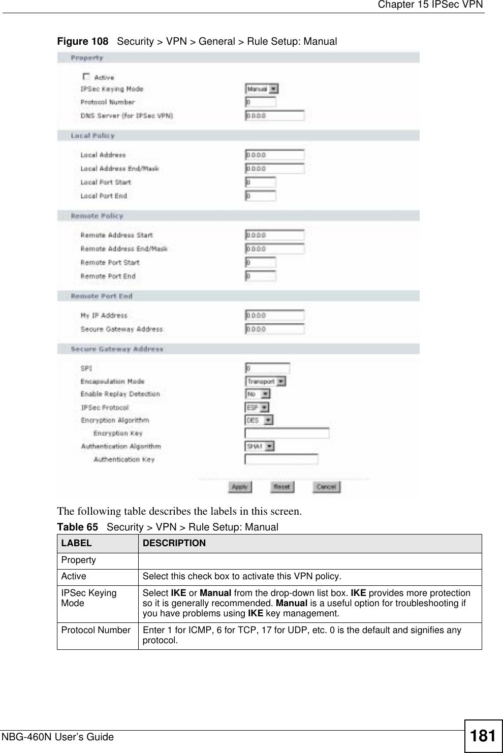
![Chapter 21 LogsNBG-460N User’s Guide 245Rule [%d] Phase 1 ID mismatch The listed rule’s IKE phase 1 ID did not match between the router and the peer.Rule [%d] Phase 1 hash mismatchThe listed rule’s IKE phase 1 hash did not match between the router and the peer.Rule [%d] Phase 1 preshared key mismatchThe listed rule’s IKE phase 1 pre-shared key did not match between the router and the peer.Rule [%d] Tunnel built successfullyThe listed rule’s IPSec tunnel has been built successfully.Rule [%d] Peer's public key not foundThe listed rule’s IKE phase 1 peer’s public key was not found.Rule [%d] Verify peer's signature failedThe listed rule’s IKE phase 1verification of the peer’s signature failed.Rule [%d] Sending IKE request IKE sent an IKE request for the listed rule.Rule [%d] Receiving IKE requestIKE received an IKE request for the listed rule.Swap rule to rule [%d] The router changed to using the listed rule.Rule [%d] Phase 1 key length mismatchThe listed rule’s IKE phase 1 key length (with the AES encryption algorithm) did not match between the router and the peer.Rule [%d] phase 1 mismatch The listed rule’s IKE phase 1 did not match between the router and the peer.Rule [%d] phase 2 mismatch The listed rule’s IKE phase 2 did not match between the router and the peer.Rule [%d] Phase 2 key length mismatchThe listed rule’s IKE phase 2 key lengths (with the AES encryption algorithm) did not match between the router and the peer.Table 101 PKI LogsLOG MESSAGE DESCRIPTIONEnrollment successful The SCEP online certificate enrollment was successful. The Destination field records the certification authority server IP address and port.Enrollment failed The SCEP online certificate enrollment failed. The Destination field records the certification authority server’s IP address and port.Failed to resolve <SCEP CA server url>The SCEP online certificate enrollment failed because the certification authority server’s address cannot be resolved.Enrollment successful The CMP online certificate enrollment was successful. The Destination field records the certification authority server’s IP address and port.Enrollment failed The CMP online certificate enrollment failed. The Destination field records the certification authority server’s IP address and port.Failed to resolve <CMP CA server url>The CMP online certificate enrollment failed because the certification authority server’s IP address cannot be resolved.Rcvd ca cert: <subject name>The router received a certification authority certificate, with subject name as recorded, from the LDAP server whose IP address and port are recorded in the Source field.Table 100 IKE Logs (continued)LOG MESSAGE DESCRIPTION](https://usermanual.wiki/ZyXEL-Communications/X550NHV2.User-Manual-2/User-Guide-1010532-Page-95.png)