ZyXEL Communications X550NHV2 High-gain Wireless N Gigabit Router User Manual 2
ZyXEL Communications Corporation High-gain Wireless N Gigabit Router 2
Contents
- 1. User Manual 1
- 2. User Manual 2
- 3. User Manual 3
User Manual 2

151
PART III
Security
Firewall (153)
Content Filtering (161)
IPSec VPN (165)

152

NBG-460N User’s Guide 153
CHAPTER 13
Firewall
This chapter gives some background information on firewalls and explains how to get started
with the NBG-460N’s firewall.
13.1 Introduction to ZyXEL’s Firewall
13.1.1 What is a Firewall?
Originally, the term “firewall” referred to a construction technique designed to prevent the
spread of fire from one room to another. The networking term "firewall" is a system or group
of systems that enforces an access-control policy between two networks. It may also be
defined as a mechanism used to protect a trusted network from a network that is not trusted. Of
course, firewalls cannot solve every security problem. A firewall is one of the mechanisms
used to establish a network security perimeter in support of a network security policy. It
should never be the only mechanism or method employed. For a firewall to guard effectively,
you must design and deploy it appropriately. This requires integrating the firewall into a broad
information-security policy. In addition, specific policies must be implemented within the
firewall itself.
13.1.2 Stateful Inspection Firewall
Stateful inspection firewalls restrict access by screening data packets against defined access
rules. They make access control decisions based on IP address and protocol. They also
"inspect" the session data to assure the integrity of the connection and to adapt to dynamic
protocols. These firewalls generally provide the best speed and transparency; however, they
may lack the granular application level access control or caching that some proxies support.
Firewalls, of one type or another, have become an integral part of standard security solutions
for enterprises.
13.1.3 About the NBG-460N Firewall
The NBG-460N firewall is a stateful inspection firewall and is designed to protect against
Denial of Service attacks when activated (click the General tab under Firewall and then click
the Enable Firewall check box). The NBG-460N's purpose is to allow a private Local Area
Network (LAN) to be securely connected to the Internet. The NBG-460N can be used to
prevent theft, destruction and modification of data, as well as log events, which may be
important to the security of your network.

Chapter 13 Firewall
NBG-460N User’s Guide
154
The NBG-460N is installed between the LAN and a broadband modem connecting to the
Internet. This allows it to act as a secure gateway for all data passing between the Internet and
the LAN.
The NBG-460N has one Ethernet WAN port and four Ethernet LAN ports, which are used to
physically separate the network into two areas.The WAN (Wide Area Network) port attaches
to the broadband (cable or DSL) modem to the Internet.
The LAN (Local Area Network) port attaches to a network of computers, which needs security
from the outside world. These computers will have access to Internet services such as e-mail,
FTP and the World Wide Web. However, "inbound access" is not allowed (by default) unless
the remote host is authorized to use a specific service.
13.1.4 Guidelines For Enhancing Security With Your Firewall
1Change the default password via web configurator.
2Think about access control before you connect to the network in any way, including
attaching a modem to the port.
3Limit who can access your router.
4Don't enable any local service (such as SNMP or NTP) that you don't use. Any enabled
service could present a potential security risk. A determined hacker might be able to find
creative ways to misuse the enabled services to access the firewall or the network.
5For local services that are enabled, protect against misuse. Protect by configuring the
services to communicate only with specific peers, and protect by configuring rules to
block packets for the services at specific interfaces.
6Protect against IP spoofing by making sure the firewall is active.
7Keep the firewall in a secured (locked) room.
13.2 Triangle Routes
If an alternate gateway on the LAN has an IP address in the same subnet as the NBG-460N’s
LAN IP address, return traffic may not go through the NBG-460N. This is called an
asymmetrical or “triangle” route. This causes the NBG-460N to reset the connection, as the
connection has not been acknowledged.
You can have the NBG-460N permit the use of asymmetrical route topology on the network
(not reset the connection).
Allowing asymmetrical routes may let traffic from the WAN go directly to the LAN without
passing through the NBG-460N. A better solution is to use IP alias to put the NBG-460N and
the backup gateway on separate subnets.
13.2.1 Triangle Routes and IP Alias
You can use IP alias instead of allowing triangle routes. IP Alias allow you to partition your
network into logical sections over the same interface.
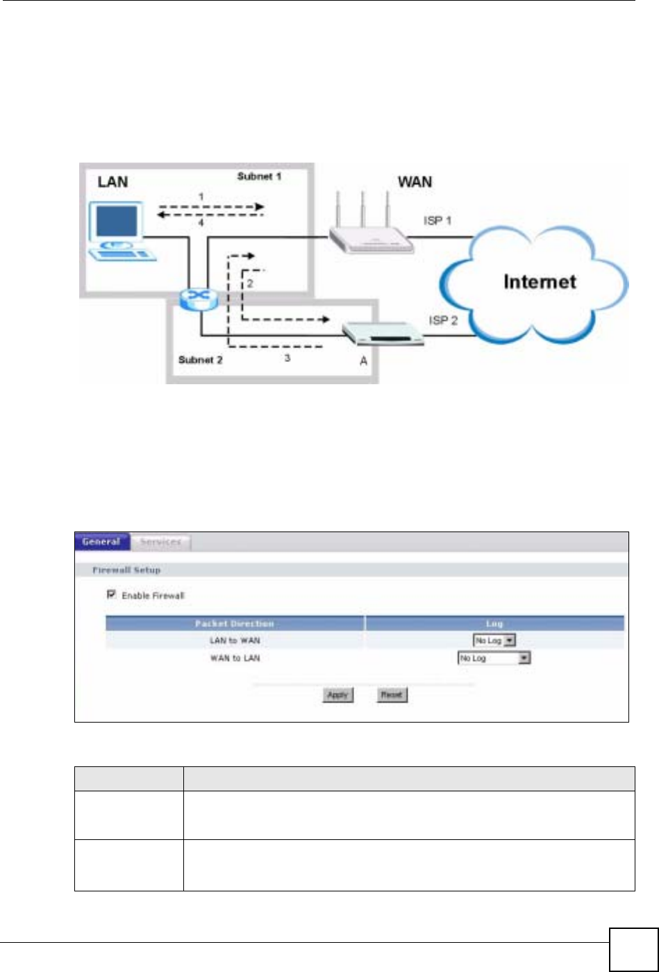
By putting your LAN and Gateway A in different subnets, all returning network traffic must
pass through the NBG-460N to your LAN. The following steps describe such a scenario.
Chapter 13 Firewall
NBG-460N User’s Guide 155
1A computer on the LAN initiates a connection by sending a SYN packet to a receiving
server on the WAN.
2The NBG-460N reroutes the packet to Gateway A, which is in Subnet 2.
3The reply from the WAN goes to the NBG-460N.
4The NBG-460N then sends it to the computer on the LAN in Subnet 1.
Figure 96 Using IP Alias to Solve the Triangle Route Problem
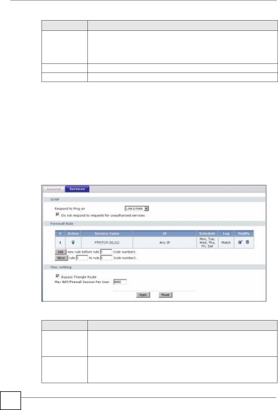
13.3 General Firewall Screen
Click Security > Firewall to open the General screen. Use this screen to enable or disable the
NBG-460N’s firewall, and set up firewall logs.
Figure 97 Security > Firewall > General l
The following table describes the labels in this screen.
Table 57 Security > Firewall > General
LABEL DESCRIPTION
Enable Firewall Select this check box to activate the firewall. The NBG-460N performs access
control and protects against Denial of Service (DoS) attacks when the firewall is
activated.
Packet Direction This is the direction of travel of packets.
Firewall rules are grouped based on the direction of travel of packets to which they
apply.
Chapter 13 Firewall
NBG-460N User’s Guide
156
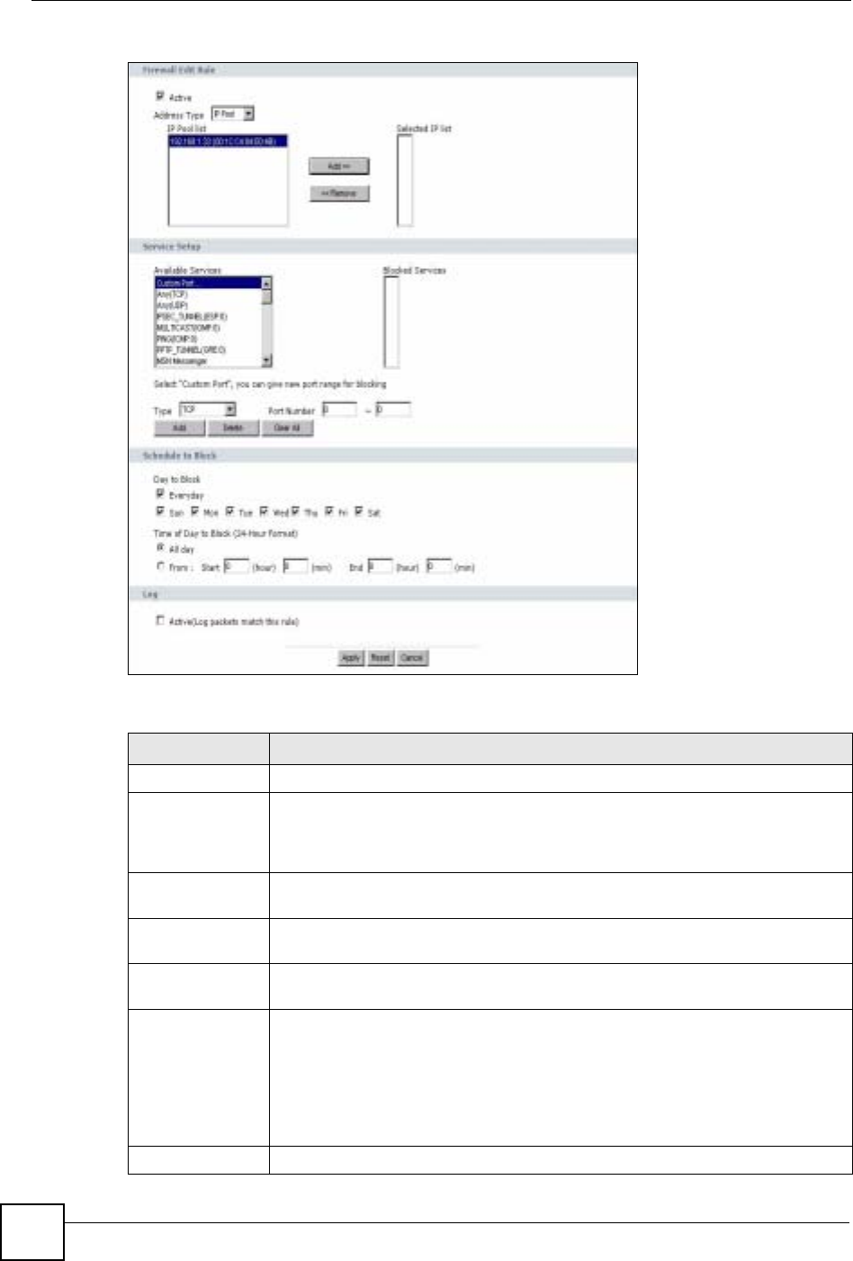
13.4 Services Screen
Click Security > Firewall > Services. The screen appears as shown next.
If an outside user attempts to probe an unsupported port on your NBG-460N, an ICMP
response packet is automatically returned. This allows the outside user to know the NBG-
460N exists. Use this screen to prevent the ICMP response packet from being sent. This keeps
outsiders from discovering your NBG-460N when unsupported ports are probed.
You can also use this screen to enable service blocking, enter/delete/modify the services you
want to block and the date/time you want to block them.
Figure 98 Security > Firewall > Services
The following table describes the labels in this screen.
Log Select whether to create a log for packets that are traveling in the selected
direction when the packets are blocked (Log All) or forwarded (Log Forward). Or
select Not Log to not log any records.
To log packets related to firewall rules, make sure that Access Control under Log
is selected in the Logs > Log Settings screen.
Apply Click Apply to save the settings.
Reset Click Reset to start configuring this screen again.
Table 57 Security > Firewall > General
LABEL DESCRIPTION
Table 58 Security > Firewall > Services
LABEL DESCRIPTION
ICMP Internet Control Message Protocol is a message control and error-reporting
protocol between a host server and a gateway to the Internet. ICMP uses Internet
Protocol (IP) datagrams, but the messages are processed by the TCP/IP software
and directly apparent to the application user.
Respond to Ping
on The NBG-460N will not respond to any incoming Ping requests when Disable is
selected. Select LAN to reply to incoming LAN Ping requests. Select WAN to reply
to incoming WAN Ping requests. Otherwise select LAN & WAN to reply to all
incoming LAN and WAN Ping requests.

Chapter 13 Firewall
NBG-460N User’s Guide 157
13.4.1 The Add Firewall Rule Screen
If you click Add or the Modify icon on an existing rule, the Add Firewall Rule screen is
displayed. Use this screen to add a firewall rule or to modify an existing one.
Do not respond to
requests for
unauthorized
services
Select this option to prevent hackers from finding the NBG-460N by probing for
unused ports. If you select this option, the NBG-460N will not respond to port
request(s) for unused ports, thus leaving the unused ports and the NBG-460N
unseen. By default this option is not selected and the NBG-460N will reply with an
ICMP Port Unreachable packet for a port probe on its unused UDP ports, and a
TCP Reset packet for a port probe on its unused TCP ports.
Note that the probing packets must first traverse the NBG-460N's firewall
mechanism before reaching this anti-probing mechanism. Therefore if the firewall
mechanism blocks a probing packet, the NBG-460N reacts based on the firewall
policy, which by default, is to send a TCP reset packet for a blocked TCP packet.
You can use the command "sys firewall tcprst rst [on|off]" to change this policy.
When the firewall mechanism blocks a UDP packet, it drops the packet without
sending a response packet.
Firewall Rule
# This is your firewall rule number. The ordering of your rules is important as rules
are applied in turn. Use the Move button to rearrange the order of the rules.
Active This icon is green when the rule is turned on. The icon is grey when the rule is
turned off.
Service Name This field displays the services and port numbers to which this firewall rule applies.
IP This field displays the IP address(es) the rule applies to.
Schedule This field displays the days the firewall rule is active.
Log This field shows you whether a log will be created when packets match the rule
(Match) or not (No).
Modify Click the Edit icon to modify an existing rule setting in the fields under the Add
Firewall Rule screen.
Click the Remove icon to delete a rule. Note that subsequent firewall rules move
up by one when you take this action.
Add Click the Add button to display the screen where you can configure a new firewall
rule. Modify the number in the textbox to add the rule before a specific rule
number.
Move The Move button moves a rule to a different position. In the first text box enter the
number of the rule you wish to move. In the second text box enter the number of
the rule you wish to move the first rule to and click the Move button.
Misc setting
Bypass Triangle
Route Select this check box to have the NBG-460N firewall ignore the use of triangle
route topology on the network.
Max NAT/Firewall
Session Per User Type a number ranging from 1 to 2048 to limit the number of NAT/firewall sessions
that a host can create.
Apply Click Apply to save the settings.
Reset Click Reset to start configuring this screen again.
Table 58 Security > Firewall > Services
LABEL DESCRIPTION
Chapter 13 Firewall
NBG-460N User’s Guide
158
Figure 99 Security > Firewall > Services > Adding a Rule
The following table describes the labels in this screen.
Table 59 Security > Firewall > Services > Adding a Rule
LABEL DESCRIPTION
Active Select this check box to turn the rule on.
Address Type Do you want your rule to apply to packets with a particular (single) IP, a range of
IP addresses (for example 192.168.1.10 to 192.169.1.50), a pool of IP address or
any IP address? Select an option from the drop-down list box that includes: Any
IP,Single IP,IP Range and IP Pool.
IP Address Enter the single IP address here. This field is only available when Single IP is
selected as the Address Type.
Start IP Address Enter the starting IP address in a range here. This field is only available when IP
Range is selected as the Address Type.
End IP Address Enter the ending IP address in a range here. This field is only available when IP
Range is selected as the Address Type.
IP Pool List Add an IP address from the IP Pool List to the Selected IP List by highlighting an
IP address and clicking Add. To delete an IP address from the Selected IP List
highlight an IP address and click the Remove button. These fields are only
available when IP Pool is selected as the Address Type.
The IP Pool list gathers its IPs from entries in the ARP table. The ARP table
contains the IP addresses and MAC addresses of the devices that have sent
traffic to the NBG-460N.
Service Setup

Chapter 13 Firewall
NBG-460N User’s Guide 159
Available
Services This is a list of pre-defined services (ports) you may prohibit your LAN computers
from using. Select the port you want to block using the drop-down list and click
Add to add the port to the Blocked Services field.
Blocked Services This is a list of services (ports) that will be inaccessible to computers on your LAN
once you enable service blocking.
Custom Port A custom port is a service that is not available in the pre-defined Available
Services list and you must define using the next two fields.
Type Choose the IP port (TCP or UDP) that defines your customized port from the drop
down list box.
Port Number Enter the port number range that defines the service. For example, if you want to
define the Gnutella service, then select TCP type and enter a port range from
6345 to 6349.
Add Select a service from the Available Services drop-down list and then click Add to
add a service to the Blocked Services
Delete Select a service from the Blocked Services list and then click Delete to remove
this service from the list.
Clear All Click Clear All to empty the Blocked Services.
Schedule to Block
Day to Block: Select a check box to configure which days of the week (or everyday) you want
service blocking to be active.
Time of Day to
Block (24-Hour
Format)
Select the time of day you want service blocking to take effect. Configure blocking
to take effect all day by selecting All Day. You can also configure specific times by
selecting From and entering the start time in the Start (hour) and Start (min)
fields and the end time in the End (hour) and End (min) fields. Enter times in 24-
hour format, for example, "3:00pm" should be entered as "15:00".
Log
Active (Log
packets match
this rule)
Select this to log packets that match this rule. Go to the Log Settings page and
select the Access Control logs category to have the NBG-460N record these
logs.
Misc setting
Bypass Triangle
Route Select this check box to have the NBG-460N firewall ignore the use of triangle
route topology on the network.
Max NAT/Firewall
Session Per User Type a number ranging from 1 to 2048 to limit the number of NAT/firewall sessions
that a host can create.
Apply Click Apply to save the settings.
Reset Click Reset to start configuring this screen again.
Cancel Click Cancel to return to the Services screen without saving any changes.
Table 59 Security > Firewall > Services > Adding a Rule
LABEL DESCRIPTION

Chapter 13 Firewall
NBG-460N User’s Guide
160

NBG-460N User’s Guide 161
CHAPTER 14
Content Filtering
This chapter provides a brief overview of content filtering using the embedded web GUI.
14.1 Introduction to Content Filtering
Internet content filtering allows you to create and enforce Internet access policies tailored to
your needs. Content filtering is the ability to block certain web features or specific URL
keywords.
14.2 Restrict Web Features
The NBG-460N can block web features such as ActiveX controls, Java applets, cookies and
disable web proxies.
14.3 Days and Times
The NBG-460N also allows you to define time periods and days during which the NBG-460N
performs content filtering.
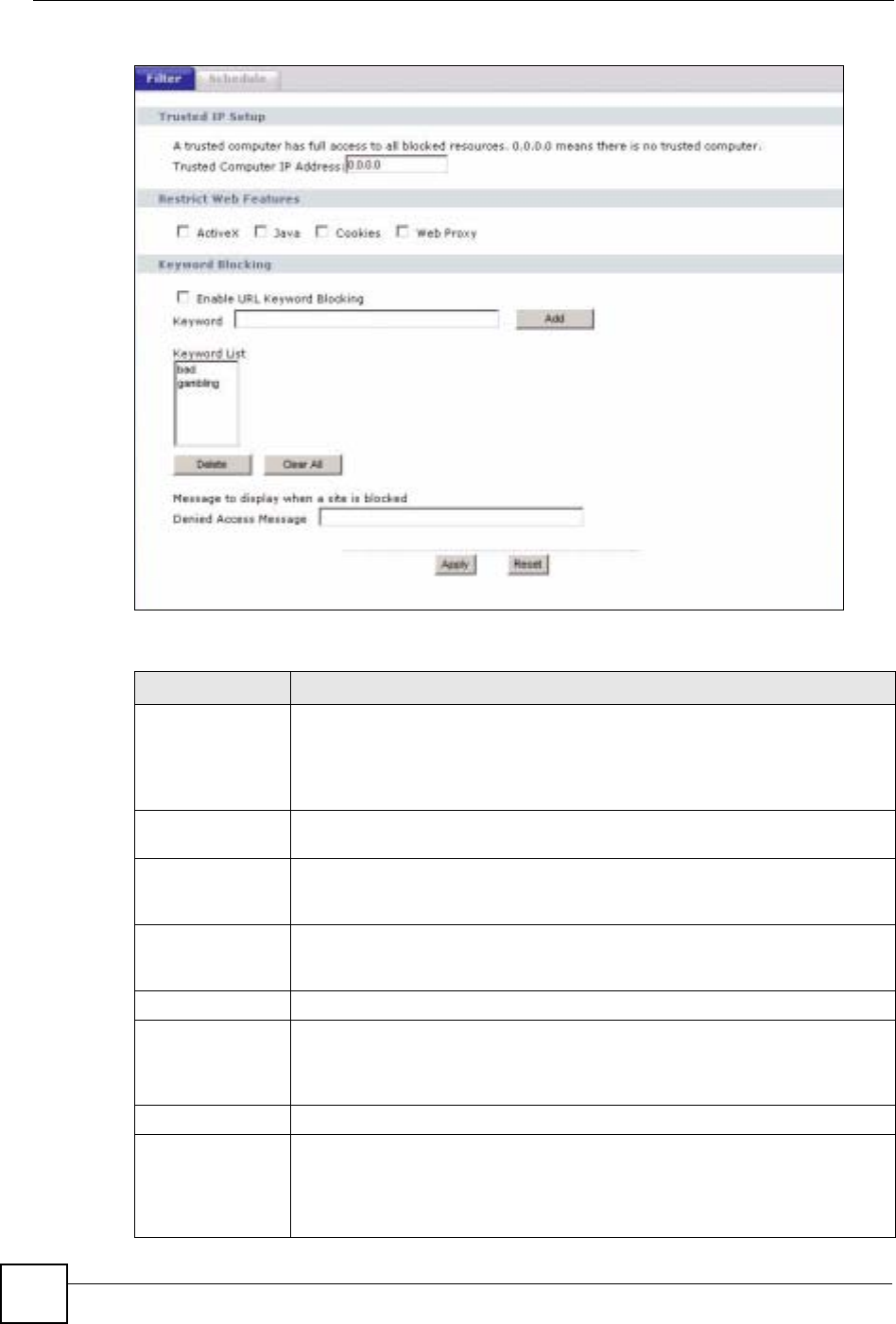
14.4 Filter Screen
Click Security > Content Filter to open the Filter screen.
Chapter 14 Content Filtering
NBG-460N User’s Guide
162
Figure 100 Security > Content Filter > Filter
The following table describes the labels in this screen.
Table 60 Security > Content Filter > Filter
LABEL DESCRIPTION
Trusted Computer
IP Address To enable this feature, type an IP address of any one of the computers in your
network that you want to have as a trusted computer. This allows the trusted
computer to have full access to all features that are configured to be blocked by
content filtering.
Leave this field blank to have no trusted computers.
Restrict Web
Features Select the box(es) to restrict a feature. When you download a page containing a
restricted feature, that part of the web page will appear blank or grayed out.
ActiveX A tool for building dynamic and active Web pages and distributed object
applications. When you visit an ActiveX Web site, ActiveX controls are
downloaded to your browser, where they remain in case you visit the site again.
Java A programming language and development environment for building
downloadable Web components or Internet and intranet business applications of
all kinds.
Cookies Used by Web servers to track usage and provide service based on ID.
Web Proxy A server that acts as an intermediary between a user and the Internet to provide
security, administrative control, and caching service. When a proxy server is
located on the WAN it is possible for LAN users to circumvent content filtering by
pointing to this proxy server.
Keyword Blocking
Enable URL
Keyword Blocking The NBG-460N can block Web sites with URLs that contain certain keywords in
the domain name or IP address. For example, if the keyword "bad" was enabled,
all sites containing this keyword in the domain name or IP address will be
blocked, e.g., URL http://www.website.com/bad.html would be blocked. Select
this check box to enable this feature.
Chapter 14 Content Filtering
NBG-460N User’s Guide 163
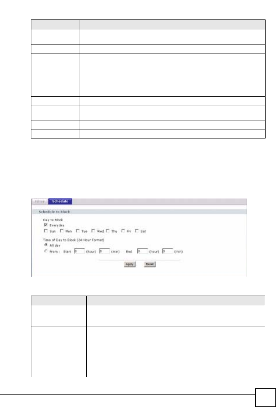
14.5 Schedule
Use this screen to set the day(s) and time you want the NBG-460N to use content filtering.
Click Security > Content Filter > Schedule. The following screen displays.
Figure 101 Security > Content Filter > Schedule
The following table describes the labels in this screen.
Keyword Type a keyword in this field. You may use any character (up to 64 characters).
Wildcards are not allowed. You can also enter a numerical IP address.
Keyword List This list displays the keywords already added.
Add Click Add after you have typed a keyword.
Repeat this procedure to add other keywords. Up to 64 keywords are allowed.
When you try to access a web page containing a keyword, you will get a
message telling you that the content filter is blocking this request.
Delete Highlight a keyword in the lower box and click Delete to remove it. The keyword
disappears from the text box after you click Apply.
Clear All Click this button to remove all of the listed keywords.
Denied Access
Message Enter a message to be displayed when a user tries to access a restricted web
site. The default message is “Please contact your network administrator!!”
Apply Click Apply to save your changes.
Reset Click Reset to begin configuring this screen afresh
Table 60 Security > Content Filter > Filter
LABEL DESCRIPTION
Table 61 Security > Content Filter > Schedule
LABEL DESCRIPTION
Day to Block Select check boxes for the days that you want the NBG-460N to perform
content filtering. Select the Everyday check box to have content filtering
turned on all days of the week.
Time of Day to Block
(24-Hour Format) Time of Day to Block allows the administrator to define during which time
periods content filtering is enabled. Time of Day to Block restrictions only
apply to the keywords (see above). Restrict web server data, such as ActiveX,
Java, Cookies and Web Proxy are not affected.
Select All Day to have content filtering always active on the days selected in
Day to Block with time of day limitations not enforced.
Select From and enter the time period, in 24-hour format, during which
content filtering will be enforced.

Chapter 14 Content Filtering
NBG-460N User’s Guide
164
14.6 Customizing Keyword Blocking URL Checking
You can use commands to set how much of a website’s URL the content filter is to check for
keyword blocking. See the appendices for information on how to access and use the command
interpreter.
14.6.1 Domain Name or IP Address URL Checking
By default, the NBG-460N checks the URL’s domain name or IP address when performing
keyword blocking.
This means that the NBG-460N checks the characters that come before the first slash in the
URL.
For example, with the URL www.zyxel.com.tw/news/pressroom.php, content filtering only
searches for keywords within www.zyxel.com.tw.
14.6.2 Full Path URL Checking
Full path URL checking has the NBG-460N check the characters that come before the last
slash in the URL.
For example, with the URL www.zyxel.com.tw/news/pressroom.php, full path URL checking
searches for keywords within www.zyxel.com.tw/news/.
Use the ip urlfilter customize actionFlags 6 [disable | enable]
command to extend (or not extend) the keyword blocking search to include the URL's full
path.
14.6.3 File Name URL Checking
Filename URL checking has the NBG-460N check all of the characters in the URL.
For example, filename URL checking searches for keywords within the URL
www.zyxel.com.tw/news/pressroom.php.
Use the ip urlfilter customize actionFlags 8 [disable | enable]
command to extend (or not extend) the keyword blocking search to include the URL's
complete filename.
Apply Click Apply to save your customized settings and exit this screen.
Reset Click Reset to begin configuring this screen afresh
Table 61 Security > Content Filter > Schedule
LABEL DESCRIPTION
NBG-460N User’s Guide 165
CHAPTER 15
IPSec VPN
15.1 IPSec VPN Overview
A virtual private network (VPN) provides secure communications between sites without the
expense of leased site-to-site lines. A secure VPN is a combination of tunneling, encryption,
authentication, access control and auditing. It is used to transport traffic over the Internet or
any insecure network that uses TCP/IP for communication.
Internet Protocol Security (IPSec) is a standards-based VPN that offers flexible solutions for
secure data communications across a public network like the Internet. IPSec is built around a
number of standardized cryptographic techniques to provide confidentiality, data integrity and
authentication at the IP layer.
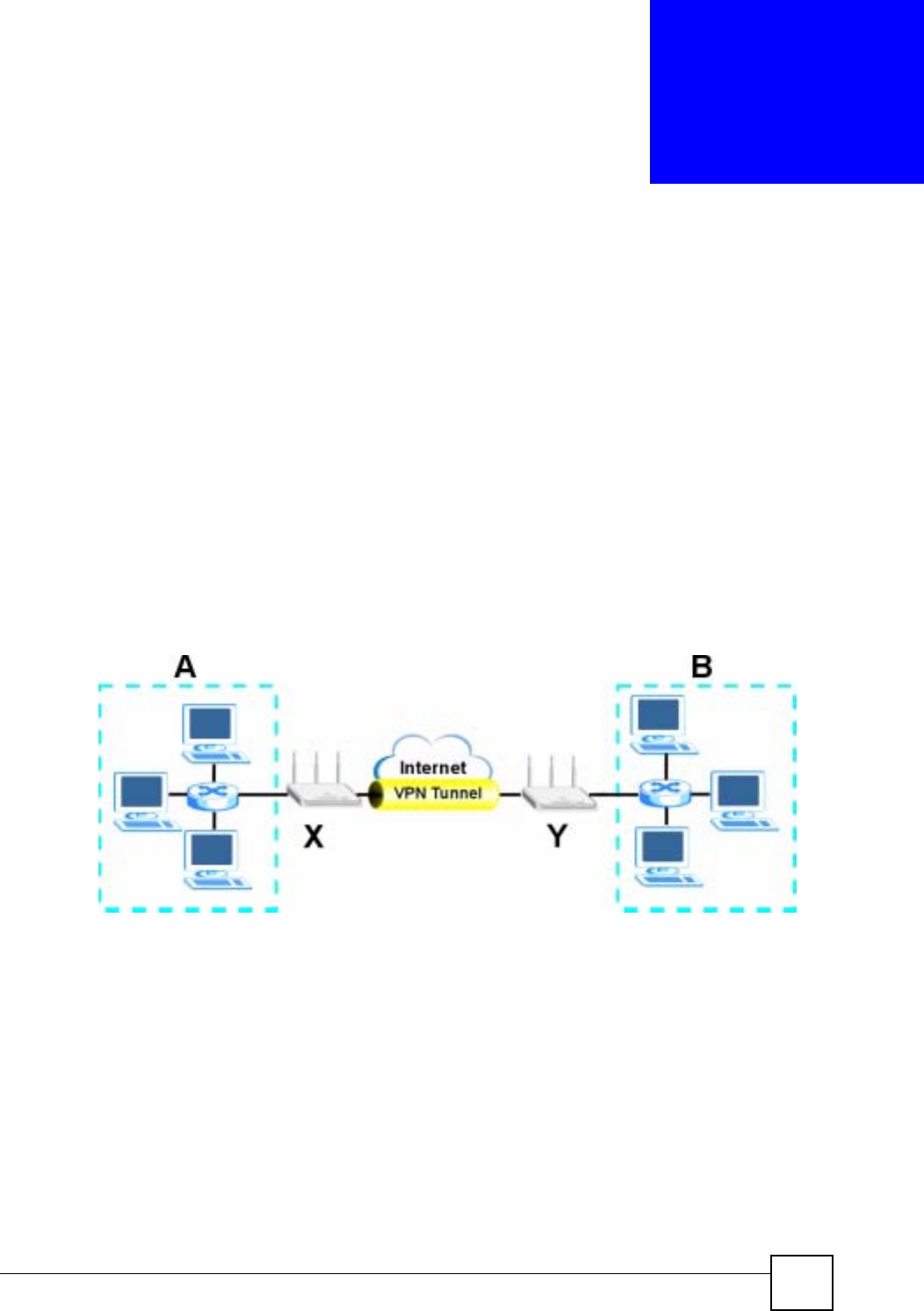
The following figure provides one perspective of a VPN tunnel.
Figure 102 IPSec VPN: Overview
The VPN tunnel connects the NBG-460N (X) and the remote IPSec router (Y). These routers
then connect the local network (A) and remote network (B).
15.1.1 What You Can Do in the IPSec VPN Screens
Use the General Screen (Section 15.2 on page 167) to display and manage the NBG-460N’s
VPN rules (tunnels).
Use the SA Monitor Screen (Section 15.3 on page 184) to display and manage active VPN
connections.
Chapter 15 IPSec VPN
NBG-460N User’s Guide
166
15.1.2 What You Need To Know About IPSec VPN
A VPN tunnel is usually established in two phases. Each phase establishes a security
association (SA), a contract indicating what security parameters the NBG-460N and the
remote IPSec router will use. The first phase establishes an Internet Key Exchange (IKE) SA
between the NBG-460N and remote IPSec router. The second phase uses the IKE SA to
securely establish an IPSec SA through which the NBG-460N and remote IPSec router can
send data between computers on the local network and remote network. The following figure
illustrates this.
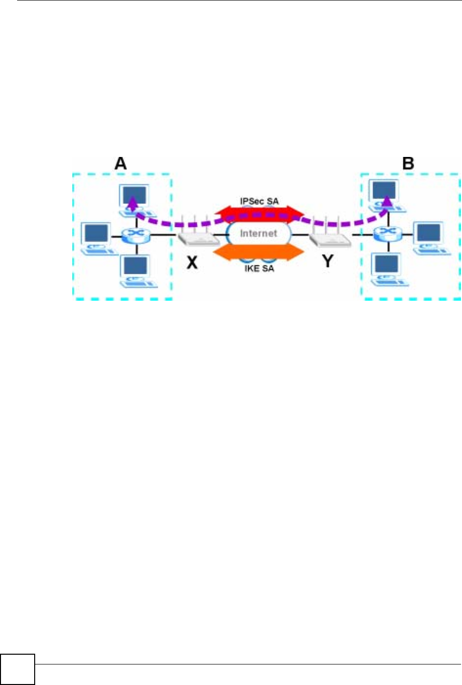
Figure 103 VPN: IKE SA and IPSec SA
In this example, a computer in network A is exchanging data with a computer in network B.
Inside networks A and B, the data is transmitted the same way data is normally transmitted in
the networks. Between routers X and Y, the data is protected by tunneling, encryption,
authentication, and other security features of the IPSec SA. The IPSec SA is established
securely using the IKE SA that routers X and Y established first.
15.1.3 IKE SA (IKE Phase 1) Overview
The IKE SA provides a secure connection between the NBG-460N and remote IPSec router.
It takes several steps to establish an IKE SA. The negotiation mode determines the number of
steps to use. There are two negotiation modes--main mode and aggressive mode. Main mode
provides better security, while aggressive mode is faster.
Note: Both routers must use the same negotiation mode.
These modes are discussed in more detail in Negotiation Mode on page 188. Main mode is
used in various examples in the rest of this section.
15.1.3.1 IP Addresses of the NBG-460N and Remote IPSec Router
In the NBG-460N, you have to specify the IP addresses of the NBG-460N and the remote
IPSec router to establish an IKE SA.
You can usually provide a static IP address or a domain name for the NBG-460N. Sometimes,
your NBG-460N might also offer another alternative, such as using the IP address of a port or
interface.
Chapter 15 IPSec VPN
NBG-460N User’s Guide 167
You can usually provide a static IP address or a domain name for the remote IPSec router as
well. Sometimes, you might not know the IP address of the remote IPSec router (for example,
telecommuters). In this case, you can still set up the IKE SA, but only the remote IPSec router
can initiate an IKE SA.
15.1.4 IPSec SA (IKE Phase 2) Overview
Once the NBG-460N and remote IPSec router have established the IKE SA, they can securely
negotiate an IPSec SA through which to send data between computers on the networks.
Note: The IPSec SA stays connected even if the underlying IKE SA is not available
anymore.
This section introduces the key components of an IPSec SA.
15.1.4.1 Local Network and Remote Network
In an IPSec SA, the local network consists of devices connected to the NBG-460N and may be
called the local policy. Similarly, the remote network consists of the devices connected to the
remote IPSec router and may be called the remote policy.
Note: It is not recommended to set a VPN rule’s local and remote network settings
both to 0.0.0.0 (any). This causes the NBG-460N to try to forward all access
attempts (to the local network, the Internet or even the NBG-460N) to the
remote IPSec router. In this case, you can no longer manage the NBG-460N.
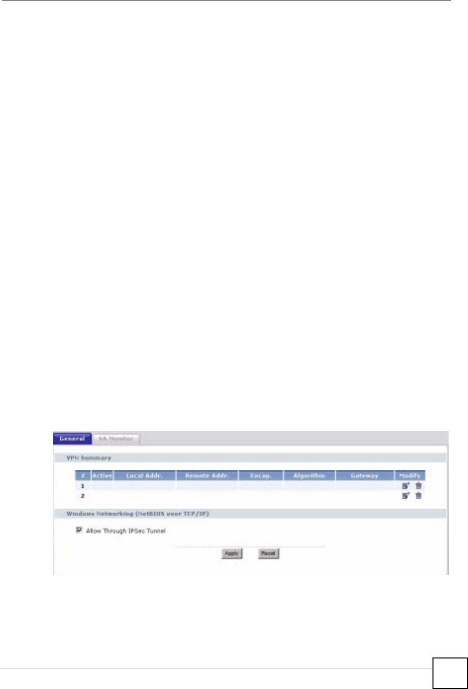
15.2 The General Screen
Click Security > VPN to display the Summary screen. This is a read-only menu of your VPN
rules (tunnels). Edit a VPN rule by clicking the Edit icon.
Figure 104 Security > VPN > General

Chapter 15 IPSec VPN
NBG-460N User’s Guide
168
The following table describes the fields in this screen.
15.2.1 VPN Rule Setup (Basic)
Click the Edit icon in the General screen to display the Rule Setup screen.
This figure helps explain the main fields.
Table 62 Security > VPN > General
LABEL DESCRIPTION
#This is the VPN policy index number.
Active This field displays whether the VPN policy is active or not.
This icon is turned on when the rule is enabled.
Local Addr. This displays the beginning and ending (static) IP addresses or a (static) IP address
and a subnet mask of computer(s) on your local network behind your NBG-460N.
Remote Addr. This displays the beginning and ending (static) IP addresses or a (static) IP address
and a subnet mask of computer(s) on the remote network behind the remote IPSec
router.
This field displays 0.0.0.0 when the Secure Gateway Address field displays 0.0.0.0.
In this case only the remote IPSec router can initiate the VPN.
Encap. This field displays Tunnel or Transport mode (Tunnel is the default selection).
Algorithm This field displays the security protocol, encryption algorithm and authentication
algorithm used for an SA.
Gateway This is the static WAN IP address or URL of the remote IPSec router. This field
displays 0.0.0.0 when you configure the Secure Gateway Address field in the Rule
Setup screen to 0.0.0.0.
Modify Click the Edit icon to go to the screen where you can edit the VPN rule.
Click the Remove icon to remove an existing VPN rule.
Windows
Networking
(NetBIOS over
TCP/IP)
NetBIOS (Network Basic Input/Output System) are TCP or UDP packets that enable
a computer to find other computers. It may sometimes be necessary to allow
NetBIOS packets to pass through VPN tunnels in order to allow local computers to
find computers on the remote network and vice versa.
Allow NetBIOS
Traffic Through
IPSec Tunnel
Select this check box to send NetBIOS packets through the VPN connection.
Apply Click Apply to save your changes back to the NBG-460N.
Reset Click Reset to begin configuring this screen afresh.

Chapter 15 IPSec VPN
NBG-460N User’s Guide 169
Figure 105 IPSec Fields Summary
Use this screen to configure a VPN rule.
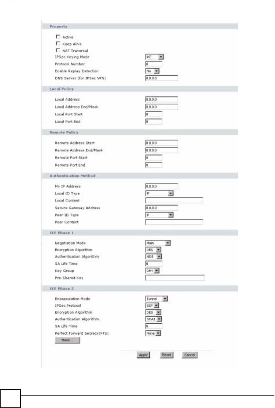
Figure 106 Security > VPN > General > Rule Setup: IKE (Basic)

Chapter 15 IPSec VPN
NBG-460N User’s Guide
170
The following table describes the labels in this screen.
Table 63 SECURITY > VPN > Rule Setup: IKE (Basic)
LABEL DESCRIPTION
Property
Active Select this check box to activate this VPN policy.
Keep Alive Select this check box to have the NBG-460N automatically reinitiate the SA after
the SA lifetime times out, even if there is no traffic. The remote IPSec router must
also have keep alive enabled in order for this feature to work.
NAT Traversal Select this check box to enable NAT traversal. NAT traversal allows you to set up
a VPN connection when there are NAT routers between the two IPSec routers.
Note: The remote IPSec router must also have NAT traversal
enabled.
You can use NAT traversal with ESP protocol using Transport or Tunnel mode,
but not with AH protocol nor with manual key management. In order for an IPSec
router behind a NAT router to receive an initiating IPSec packet, set the NAT
router to forward UDP ports 500 and 4500 to the IPSec router behind the NAT
router.
IPSec Keying
Mode Select IKE or Manual from the drop-down list box. IKE provides more protection
so it is generally recommended. Manual is a useful option for troubleshooting if
you have problems using IKE key management.
DNS Server (for
IPSec VPN) If there is a private DNS server that services the VPN, type its IP address here.
The NBG-460N assigns this additional DNS server to the NBG-460N's DHCP
clients that have IP addresses in this IPSec rule's range of local addresses.
A DNS server allows clients on the VPN to find other computers and servers on
the VPN by their (private) domain names.
Local Policy Local IP addresses must be static and correspond to the remote IPSec router's
configured remote IP addresses.
Two active SAs can have the same configured local or remote IP address, but not
both. You can configure multiple SAs between the same local and remote IP
addresses, as long as only one is active at any time.
In order to have more than one active rule with the Secure Gateway Address
field set to 0.0.0.0, the ranges of the local IP addresses cannot overlap between
rules.
If you configure an active rule with 0.0.0.0 in the Secure Gateway Address field
and the LAN’s full IP address range as the local IP address, then you cannot
configure any other active rules with the Secure Gateway Address field set to
0.0.0.0.
Local Address For a single IP address, enter a (static) IP address on the LAN behind your NBG-
460N.
For a specific range of IP addresses, enter the beginning (static) IP address, in a
range of computers on your LAN behind your NBG-460N.
To specify IP addresses on a network by their subnet mask, enter a (static) IP
address on the LAN behind your NBG-460N.
Local Address End
/Mask When the local IP address is a single address, type it a second time here.
When the local IP address is a range, enter the end (static) IP address, in a range
of computers on the LAN behind your NBG-460N.
When the local IP address is a subnet address, enter a subnet mask on the LAN
behind your NBG-460N.

Chapter 15 IPSec VPN
NBG-460N User’s Guide 171
Remote Policy Remote IP addresses must be static and correspond to the remote IPSec router's
configured local IP addresses. The remote fields do not apply when the Secure
Gateway IP Address field is configured to 0.0.0.0. In this case only the remote
IPSec router can initiate the VPN.
Two active SAs cannot have the local and remote IP address(es) both the same.
Two active SAs can have the same local or remote IP address, but not both. You
can configure multiple SAs between the same local and remote IP addresses, as
long as only one is active at any time.
Remote Address For a single IP address, enter a (static) IP address on the network behind the
remote IPSec router.
For a specific range of IP addresses, enter the beginning (static) IP address, in a
range of computers on the network behind the remote IPSec router.
To specify IP addresses on a network by their subnet mask, enter a (static) IP
address on the network behind the remote IPSec router.
Remote Address
End /Mask When the remote IP address is a single address, type it a second time here.
When the remote IP address is a range, enter the end (static) IP address, in a
range of computers on the network behind the remote IPSec router.
When the remote IP address is a subnet address, enter a subnet mask on the
network behind the remote IPSec router.
Authentication
Method
My IP Address Enter the NBG-460N's static WAN IP address (if it has one) or leave the field set
to 0.0.0.0.
The NBG-460N uses its current WAN IP address (static or dynamic) in setting up
the VPN tunnel if you leave this field as 0.0.0.0. If the WAN connection goes
down, the NBG-460N uses the dial backup IP address for the VPN tunnel when
using dial backup or the LAN IP address when using traffic redirect.
Otherwise, you can enter one of the dynamic domain names that you have
configured (in the DDNS screen) to have the NBG-460N use that dynamic
domain name's IP address.
The VPN tunnel has to be rebuilt if My IP Address changes after setup.
Local ID Type Select IP to identify this NBG-460N by its IP address.
Select Domain Name to identify this NBG-460N by a domain name.
Select E-mail to identify this NBG-460N by an e-mail address.
Local Content When you select IP in the Local ID Type field, type the IP address of your
computer in the Local Content field. The NBG-460N automatically uses the IP
address in the My IP Address field (refer to the My IP Address field description)
if you configure the Local Content field to 0.0.0.0 or leave it blank.
It is recommended that you type an IP address other than 0.0.0.0 in the Local
Content field or use the Domain Name or E-mail ID type in the following
situations.
• When there is a NAT router between the two IPSec routers.
• When you want the remote IPSec router to be able to distinguish between
VPN connection requests that come in from IPSec routers with dynamic WAN
IP addresses.
When you select Domain Name or E-mail in the Local ID Type field, type a
domain name or e-mail address by which to identify this NBG-460N in the Local
Content field. Use up to 31 ASCII characters including spaces, although trailing
spaces are truncated. The domain name or e-mail address is for identification
purposes only and can be any string.
Table 63 SECURITY > VPN > Rule Setup: IKE (Basic) (continued)
LABEL DESCRIPTION

Chapter 15 IPSec VPN
NBG-460N User’s Guide
172
Secure Gateway
Address Type the WAN IP address or the domain name (up to 31 characters) of the IPSec
router with which you're making the VPN connection. Set this field to 0.0.0.0 if the
remote IPSec router has a dynamic WAN IP address (the IPSec Keying Mode
field must be set to IKE).
In order to have more than one active rule with the Secure Gateway Address
field set to 0.0.0.0, the ranges of the local IP addresses cannot overlap between
rules.
If you configure an active rule with 0.0.0.0 in the Secure Gateway Address field
and the LAN’s full IP address range as the local IP address, then you cannot
configure any other active rules with the Secure Gateway Address field set to
0.0.0.0.
Note: You can also enter a remote secure gateway’s domain
name in the Secure Gateway Address field if the remote
secure gateway has a dynamic WAN IP address and is
using DDNS. The NBG-460N has to rebuild the VPN tunnel
each time the remote secure gateway’s WAN IP address
changes (there may be a delay until the DDNS servers are
updated with the remote gateway’s new WAN IP address).
Peer ID Type Select IP to identify the remote IPSec router by its IP address.
Select Domain Name to identify the remote IPSec router by a domain name.
Select E-mail to identify the remote IPSec router by an e-mail address.
Peer Content The configuration of the peer content depends on the peer ID type.
For IP, type the IP address of the computer with which you will make the VPN
connection. If you configure this field to 0.0.0.0 or leave it blank, the NBG-460N
will use the address in the Secure Gateway Address field (refer to the Secure
Gateway Address field description).
For Domain Name or E-mail, type a domain name or e-mail address by which to
identify the remote IPSec router. Use up to 31 ASCII characters including spaces,
although trailing spaces are truncated. The domain name or e-mail address is for
identification purposes only and can be any string.
It is recommended that you type an IP address other than 0.0.0.0 or use the
Domain Name or E-mail ID type in the following situations:
• When there is a NAT router between the two IPSec routers.
• When you want the NBG-460N to distinguish between VPN connection
requests that come in from remote IPSec routers with dynamic WAN IP
addresses.
IPSec Algorithm
Encapsulation
Mode Select Tunnel mode or Transport mode from the drop-down list box.
IPSec Protocol Select the security protocols used for an SA.
Both AH and ESP increase processing requirements and communications
latency (delay).
If you select ESP here, you must select options from the Encryption Algorithm
and Authentication Algorithm fields (described below).
Table 63 SECURITY > VPN > Rule Setup: IKE (Basic) (continued)
LABEL DESCRIPTION

Chapter 15 IPSec VPN
NBG-460N User’s Guide 173
15.2.2 VPN Rule Setup (Advanced)
Click the Advanced... button in the Rule Setup screen to open this screen.
Use this screen to configure a VPN rule.
Pre-Shared Key Type your pre-shared key in this field. A pre-shared key identifies a
communicating party during a phase 1 IKE negotiation. It is called "pre-shared"
because you have to share it with another party before you can communicate
with them over a secure connection.
Type from 8 to 31 case-sensitive ASCII characters or from 16 to 62 hexadecimal
("0-9", "A-F") characters. You must precede a hexadecimal key with a "0x” (zero
x), which is not counted as part of the 16 to 62 character range for the key. For
example, in "0x0123456789ABCDEF", “0x” denotes that the key is hexadecimal
and “0123456789ABCDEF” is the key itself.
Both ends of the VPN tunnel must use the same pre-shared key. You will receive
a “PYLD_MALFORMED” (payload malformed) packet if the same pre-shared key
is not used on both ends.
Encryption
Algorithm Select which key size and encryption algorithm to use for data communications.
Choices are:
DES - a 56-bit key with the DES encryption algorithm
3DES - a 168-bit key with the DES encryption algorithm
The NBG-460N and the remote IPSec router must use the same algorithms and
key , which can be used to encrypt and decrypt the message or to generate and
verify a message authentication code. Longer keys require more processing
power, resulting in increased latency and decreased throughput.
Authentication
Algorithm Select which hash algorithm to use to authenticate packet data. Choices are
SHA1 and MD5.SHA1 is generally considered stronger than MD5, but it is also
slower.
Advanced... Click Advanced... to configure more detailed settings of your IKE key
management.
Apply Click Apply to save your changes back to the NBG-460N.
Reset Click Reset to begin configuring this screen afresh.
Cancel Click Cancel to exit the screen without making any changes.
Table 63 SECURITY > VPN > Rule Setup: IKE (Basic) (continued)
LABEL DESCRIPTION
Chapter 15 IPSec VPN
NBG-460N User’s Guide
174
Figure 107 Security > VPN > General > Rule Setup: IKE (Advanced)

Chapter 15 IPSec VPN
NBG-460N User’s Guide 175
The following table describes the labels in this screen.
Table 64 Security > VPN > Rule Setup: IKE (Advanced)
LABEL DESCRIPTION
Property
Active Select this check box to activate this VPN policy.
Keep Alive Select this check box to have the NBG-460N automatically reinitiate the SA
after the SA lifetime times out, even if there is no traffic. The remote IPSec
router must also have keep alive enabled in order for this feature to work.
NAT Traversal Select this check box to enable NAT traversal. NAT traversal allows you to set
up a VPN connection when there are NAT routers between the two IPSec
routers.
Note: The remote IPSec router must also have NAT traversal
enabled.
You can use NAT traversal with ESP protocol using Transport or Tunnel
mode, but not with AH protocol nor with manual key management. In order for
an IPSec router behind a NAT router to receive an initiating IPSec packet, set
the NAT router to forward UDP ports 500 and 4500 to the IPSec router behind
the NAT router.
IPSec Keying Mode Select IKE or Manual from the drop-down list box. IKE provides more
protection so it is generally recommended. Manual is a useful option for
troubleshooting if you have problems using IKE key management.
Protocol Number Enter 1 for ICMP, 6 for TCP, 17 for UDP, etc. 0 is the default and signifies any
protocol.
Enable Replay
Detection As a VPN setup is processing intensive, the system is vulnerable to Denial of
Service (DoS) attacks The IPSec receiver can detect and reject old or duplicate
packets to protect against replay attacks. Select Yes from the drop-down menu
to enable replay detection, or select No to disable it.
DNS Server (for
IPSec VPN) If there is a private DNS server that services the VPN, type its IP address here.
The NBG-460N assigns this additional DNS server to the NBG-460N's DHCP
clients that have IP addresses in this IPSec rule's range of local addresses.
A DNS server allows clients on the VPN to find other computers and servers on
the VPN by their (private) domain names.
Local Policy Local IP addresses must be static and correspond to the remote IPSec router's
configured remote IP addresses.
Two active SAs can have the same configured local or remote IP address, but
not both. You can configure multiple SAs between the same local and remote IP
addresses, as long as only one is active at any time.
In order to have more than one active rule with the Secure Gateway Address
field set to 0.0.0.0, the ranges of the local IP addresses cannot overlap between
rules.
If you configure an active rule with 0.0.0.0 in the Secure Gateway Address
field and the LAN’s full IP address range as the local IP address, then you
cannot configure any other active rules with the Secure Gateway Address field
set to 0.0.0.0.
Local Address For a single IP address, enter a (static) IP address on the LAN behind your
NBG-460N.
For a specific range of IP addresses, enter the beginning (static) IP address, in
a range of computers on your LAN behind your NBG-460N.
To specify IP addresses on a network by their subnet mask, enter a (static) IP
address on the LAN behind your NBG-460N.

Chapter 15 IPSec VPN
NBG-460N User’s Guide
176
Local Address End /
Mask When the local IP address is a single address, type it a second time here.
When the local IP address is a range, enter the end (static) IP address, in a
range of computers on the LAN behind your NBG-460N.
When the local IP address is a subnet address, enter a subnet mask on the
LAN behind your NBG-460N.
Local Port Start 0 is the default and signifies any port. Type a port number from 0 to 65535.
Some of the most common IP ports are: 21, FTP; 53, DNS; 23, Telnet; 80,
HTTP; 25, SMTP; 110, POP3.
Local Port End Enter a port number in this field to define a port range. This port number must
be greater than that specified in the previous field. If Local Port Start is left at
0, Local Port End will also remain at 0.
Remote Policy Remote IP addresses must be static and correspond to the remote IPSec
router's configured local IP addresses. The remote fields do not apply when the
Secure Gateway IP Address field is configured to 0.0.0.0. In this case only the
remote IPSec router can initiate the VPN.
Two active SAs cannot have the local and remote IP address(es) both the
same. Two active SAs can have the same local or remote IP address, but not
both. You can configure multiple SAs between the same local and remote IP
addresses, as long as only one is active at any time.
Remote Address For a single IP address, enter a (static) IP address on the network behind the
remote IPSec router.
For a specific range of IP addresses, enter the beginning (static) IP address, in
a range of computers on the network behind the remote IPSec router.
To specify IP addresses on a network by their subnet mask, enter a (static) IP
address on the network behind the remote IPSec router.
Remote Address
End /Mask When the remote IP address is a single address, type it a second time here.
When the remote IP address is a range, enter the end (static) IP address, in a
range of computers on the network behind the remote IPSec router.
When the remote IP address is a subnet address, enter a subnet mask on the
network behind the remote IPSec router.
Remote Port Start 0 is the default and signifies any port. Type a port number from 0 to 65535.
Some of the most common IP ports are: 21, FTP; 53, DNS; 23, Telnet; 80,
HTTP; 25, SMTP; 110, POP3.
Remote Port End Enter a port number in this field to define a port range. This port number must
be greater than that specified in the previous field. If Remote Port Start is left at
0, Remote Port End will also remain at 0.
Authentication
Method
My IP Address Enter the NBG-460N's static WAN IP address (if it has one) or leave the field
set to 0.0.0.0.
The NBG-460N uses its current WAN IP address (static or dynamic) in setting
up the VPN tunnel if you leave this field as 0.0.0.0. If the WAN connection goes
down, the NBG-460N uses the dial backup IP address for the VPN tunnel when
using dial backup or the LAN IP address when using traffic redirect.
Otherwise, you can enter one of the dynamic domain names that you have
configured (in the DDNS screen) to have the NBG-460N use that dynamic
domain name's IP address.
The VPN tunnel has to be rebuilt if My IP Address changes after setup.
Local ID Type Select IP to identify this NBG-460N by its IP address.
Select Domain Name to identify this NBG-460N by a domain name.
Select E-mail to identify this NBG-460N by an e-mail address.
Table 64 Security > VPN > Rule Setup: IKE (Advanced) (continued)
LABEL DESCRIPTION

Chapter 15 IPSec VPN
NBG-460N User’s Guide 177
Local Content When you select IP in the Local ID Type field, type the IP address of your
computer in the Local Content field. The NBG-460N automatically uses the IP
address in the My IP Address field (refer to the My IP Address field
description) if you configure the Local Content field to 0.0.0.0 or leave it blank.
It is recommended that you type an IP address other than 0.0.0.0 in the Local
Content field or use the Domain Name or E-mail ID type in the following
situations.
• When there is a NAT router between the two IPSec routers.
• When you want the remote IPSec router to be able to distinguish between
VPN connection requests that come in from IPSec routers with dynamic
WAN IP addresses.
When you select Domain Name or E-mail in the Local ID Type field, type a
domain name or e-mail address by which to identify this NBG-460N in the Local
Content field. Use up to 31 ASCII characters including spaces, although trailing
spaces are truncated. The domain name or e-mail address is for identification
purposes only and can be any string.
Secure Gateway
Address Type the WAN IP address or the domain name (up to 31 characters) of the
IPSec router with which you're making the VPN connection. Set this field to
0.0.0.0 if the remote IPSec router has a dynamic WAN IP address (the IPSec
Keying Mode field must be set to IKE).
In order to have more than one active rule with the Secure Gateway Address
field set to 0.0.0.0, the ranges of the local IP addresses cannot overlap between
rules.
If you configure an active rule with 0.0.0.0 in the Secure Gateway Address
field and the LAN’s full IP address range as the local IP address, then you
cannot configure any other active rules with the Secure Gateway Address field
set to 0.0.0.0.
Note: You can also enter a remote secure gateway’s domain
name in the Secure Gateway Address field if the remote
secure gateway has a dynamic WAN IP address and is
using DDNS. The NBG-460N has to rebuild the VPN
tunnel each time the remote secure gateway’s WAN IP
address changes (there may be a delay until the DDNS
servers are updated with the remote gateway’s new WAN
IP address).
Peer ID Type Select IP to identify the remote IPSec router by its IP address.
Select Domain Name to identify the remote IPSec router by a domain name.
Select E-mail to identify the remote IPSec router by an e-mail address.
Table 64 Security > VPN > Rule Setup: IKE (Advanced) (continued)
LABEL DESCRIPTION

Chapter 15 IPSec VPN
NBG-460N User’s Guide
178
Peer Content The configuration of the peer content depends on the peer ID type.
For IP, type the IP address of the computer with which you will make the VPN
connection. If you configure this field to 0.0.0.0 or leave it blank, the NBG-460N
will use the address in the Secure Gateway Address field (refer to the Secure
Gateway Address field description).
For Domain Name or E-mail, type a domain name or e-mail address by which
to identify the remote IPSec router. Use up to 31 ASCII characters including
spaces, although trailing spaces are truncated. The domain name or e-mail
address is for identification purposes only and can be any string.
It is recommended that you type an IP address other than 0.0.0.0 or use the
Domain Name or E-mail ID type in the following situations:
• When there is a NAT router between the two IPSec routers.
• When you want the NBG-460N to distinguish between VPN connection
requests that come in from remote IPSec routers with dynamic WAN IP
addresses.
IKE Phase 1
Negotiation Mode Select Main or Aggressive from the drop-down list box. Multiple SAs
connecting through a secure gateway must have the same negotiation mode.
Encryption Algorithm Select which key size and encryption algorithm to use in the IKE SA. Choices
are:
DES - a 56-bit key with the DES encryption algorithm
3DES - a 168-bit key with the DES encryption algorithm
The NBG-460N and the remote IPSec router must use the same algorithms and
keys. Longer keys require more processing power, resulting in increased
latency and decreased throughput.
Authentication
Algorithm Select which hash algorithm to use to authenticate packet data in the IKE SA.
Choices are SHA1 and MD5.SHA1 is generally considered stronger than MD5,
but it is also slower.
SA Life Time
(Seconds) Define the length of time before an IKE SA automatically renegotiates in this
field. It may range from 180 to 3,000,000 seconds (almost 35 days).
A short SA Life Time increases security by forcing the two VPN gateways to
update the encryption and authentication keys. However, every time the VPN
tunnel renegotiates, all users accessing remote resources are temporarily
disconnected.
Key Group Select which Diffie-Hellman key group (DHx) you want to use for encryption
keys. Choices are:
DH1 - use a 768-bit random number
DH2 - use a 1024-bit random number
Pre-Shared Key Type your pre-shared key in this field. A pre-shared key identifies a
communicating party during a phase 1 IKE negotiation. It is called "pre-shared"
because you have to share it with another party before you can communicate
with them over a secure connection.
Type from 8 to 31 case-sensitive ASCII characters or from 16 to 62
hexadecimal ("0-9", "A-F") characters. You must precede a hexadecimal key
with a "0x” (zero x), which is not counted as part of the 16 to 62 character range
for the key. For example, in "0x0123456789ABCDEF", “0x” denotes that the key
is hexadecimal and “0123456789ABCDEF” is the key itself.
Both ends of the VPN tunnel must use the same pre-shared key. You will
receive a “PYLD_MALFORMED” (payload malformed) packet if the same pre-
shared key is not used on both ends.
IKE Phase 2
Encapsulation Mode Select Tunnel mode or Transport mode.
Table 64 Security > VPN > Rule Setup: IKE (Advanced) (continued)
LABEL DESCRIPTION

Chapter 15 IPSec VPN
NBG-460N User’s Guide 179
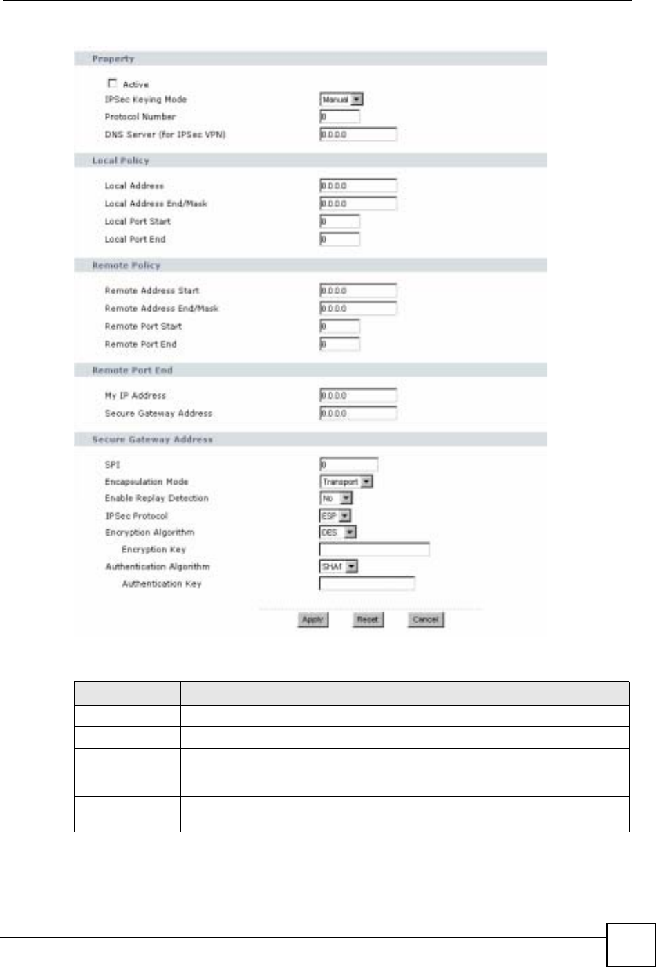
15.2.3 VPN Rule Setup (Manual)
Use this screen to configure VPN rules (tunnels) that use manual keys. Manual key
management is useful if you have problems with IKE key management.
Select Manual in the IPSec Keying Mode field on the Rule Setup screen to open the screen
as shown in Figure 108 on page 181.
15.2.3.1 IPSec SA Using Manual Keys
You might set up an IPSec SA using manual keys when you want to establish a VPN tunnel
quickly, for example, for troubleshooting. You should only do this as a temporary solution,
however, because it is not as secure as a regular IPSec SA.
IPSec Protocol Select the security protocols used for an SA.
Both AH and ESP increase processing requirements and communications
latency (delay).
If you select ESP here, you must select options from the Encryption Algorithm
and Authentication Algorithm fields (described below).
Encryption Algorithm Select which key size and encryption algorithm to use in the IKE SA. Choices
are:
DES - a 56-bit key with the DES encryption algorithm
3DES - a 168-bit key with the DES encryption algorithm
The NBG-460N and the remote IPSec router must use the same algorithms and
keys. Longer keys require more processing power, resulting in increased
latency and decreased throughput.
Authentication
Algorithm Select which hash algorithm to use to authenticate packet data in the IPSec SA.
Choices are SHA1 and MD5.SHA1 is generally considered stronger than MD5,
but it is also slower.
SA Life Time Define the length of time before an IPSec SA automatically renegotiates in this
field. The minimum value is 180 seconds.
A short SA Life Time increases security by forcing the two VPN gateways to
update the encryption and authentication keys. However, every time the VPN
tunnel renegotiates, all users accessing remote resources are temporarily
disconnected.
Perfect Forward
Secrecy (PFS) Select whether or not you want to enable Perfect Forward Secrecy (PFS) and, if
you do, which Diffie-Hellman key group to use for encryption. Choices are:
None - disable PFS
DH1 - enable PFS and use a 768-bit random number
DH2 - enable PFS and use a 1024-bit random number
PFS changes the root key that is used to generate encryption keys for each
IPSec SA. It is more secure but takes more time.
Basic... Click Basic... to go to the previous VPN configuration screen.
Apply Click Apply to save the changes.
Reset Click Reset to begin configuring this screen afresh.
Cancel Click Cancel to exit the screen without making any changes.
Table 64 Security > VPN > Rule Setup: IKE (Advanced) (continued)
LABEL DESCRIPTION

Chapter 15 IPSec VPN
NBG-460N User’s Guide
180
In IPSec SAs using manual keys, the NBG-460N and remote IPSec router do not establish an
IKE SA. They only establish an IPSec SA. As a result, an IPSec SA using manual keys has
some characteristics of IKE SA and some characteristics of IPSec SA. There are also some
differences between IPSec SA using manual keys and other types of SA.
15.2.3.2 IPSec SA Proposal Using Manual Keys
In IPSec SA using manual keys, you can only specify one encryption algorithm and one
authentication algorithm. There is no DH key exchange, so you have to provide the encryption
key and the authentication key the NBG-460N and remote IPSec router use.
Note: The NBG-460N and remote IPSec router must use the same encryption key
and authentication key.
15.2.3.3 Authentication and the Security Parameter Index (SPI)
For authentication, the NBG-460N and remote IPSec router use the SPI, instead of pre-shared
keys, ID type and content. The SPI is an identification number.
Note: The NBG-460N and remote IPSec router must use the same SPI.
Chapter 15 IPSec VPN
NBG-460N User’s Guide 181
Figure 108 Security > VPN > General > Rule Setup: Manual
The following table describes the labels in this screen.
Table 65 Security > VPN > Rule Setup: Manual
LABEL DESCRIPTION
Property
Active Select this check box to activate this VPN policy.
IPSec Keying
Mode Select IKE or Manual from the drop-down list box. IKE provides more protection
so it is generally recommended. Manual is a useful option for troubleshooting if
you have problems using IKE key management.
Protocol Number Enter 1 for ICMP, 6 for TCP, 17 for UDP, etc. 0 is the default and signifies any
protocol.

Chapter 15 IPSec VPN
NBG-460N User’s Guide
182
DNS Server (for
IPSec VPN) If there is a private DNS server that services the VPN, type its IP address here.
The NBG-460N assigns this additional DNS server to the NBG-460N's DHCP
clients that have IP addresses in this IPSec rule's range of local addresses.
A DNS server allows clients on the VPN to find other computers and servers on
the VPN by their (private) domain names.
Local Policy Local IP addresses must be static and correspond to the remote IPSec router's
configured remote IP addresses.
Two active SAs can have the same configured local or remote IP address, but not
both. You can configure multiple SAs between the same local and remote IP
addresses, as long as only one is active at any time.
In order to have more than one active rule with the Secure Gateway Address
field set to 0.0.0.0, the ranges of the local IP addresses cannot overlap between
rules.
If you configure an active rule with 0.0.0.0 in the Secure Gateway Address field
and the LAN’s full IP address range as the local IP address, then you cannot
configure any other active rules with the Secure Gateway Address field set to
0.0.0.0.
Local Address For a single IP address, enter a (static) IP address on the LAN behind your NBG-
460N.
For a specific range of IP addresses, enter the beginning (static) IP address, in a
range of computers on your LAN behind your NBG-460N.
To specify IP addresses on a network by their subnet mask, enter a (static) IP
address on the LAN behind your NBG-460N.
Local Address
End /Mask When the local IP address is a single address, type it a second time here.
When the local IP address is a range, enter the end (static) IP address, in a range
of computers on the LAN behind your NBG-460N.
When the local IP address is a subnet address, enter a subnet mask on the LAN
behind your NBG-460N.
Local Port Start 0 is the default and signifies any port. Type a port number from 0 to 65535. Some
of the most common IP ports are: 21, FTP; 53, DNS; 23, Telnet; 80, HTTP; 25,
SMTP; 110, POP3.
Local Port End Enter a port number in this field to define a port range. This port number must be
greater than that specified in the previous field. If Local Port Start is left at 0,
Local Port End will also remain at 0.
Remote Policy Remote IP addresses must be static and correspond to the remote IPSec router's
configured local IP addresses. The remote fields do not apply when the Secure
Gateway IP Address field is configured to 0.0.0.0. In this case only the remote
IPSec router can initiate the VPN.
Two active SAs cannot have the local and remote IP address(es) both the same.
Two active SAs can have the same local or remote IP address, but not both. You
can configure multiple SAs between the same local and remote IP addresses, as
long as only one is active at any time.
Remote Address For a single IP address, enter a (static) IP address on the network behind the
remote IPSec router.
For a specific range of IP addresses, enter the beginning (static) IP address, in a
range of computers on the network behind the remote IPSec router.
To specify IP addresses on a network by their subnet mask, enter a (static) IP
address on the network behind the remote IPSec router.
Table 65 Security > VPN > Rule Setup: Manual (continued)
LABEL DESCRIPTION

Chapter 15 IPSec VPN
NBG-460N User’s Guide 183
Remote Address
End /Mask When the remote IP address is a single address, type it a second time here.
When the remote IP address is a range, enter the end (static) IP address, in a
range of computers on the network behind the remote IPSec router.
When the remote IP address is a subnet address, enter a subnet mask on the
network behind the remote IPSec router.
Remote Port
Start 0 is the default and signifies any port. Type a port number from 0 to 65535. Some
of the most common IP ports are: 21, FTP; 53, DNS; 23, Telnet; 80, HTTP; 25,
SMTP; 110, POP3.
Remote Port End Enter a port number in this field to define a port range. This port number must be
greater than that specified in the previous field. If Remote Port Start is left at 0,
Remote Port End will also remain at 0.
My IP Address Enter the NBG-460N's static WAN IP address (if it has one) or leave the field set to
0.0.0.0.
The NBG-460N uses its current WAN IP address (static or dynamic) in setting up
the VPN tunnel if you leave this field as 0.0.0.0. If the WAN connection goes down,
the NBG-460N uses the dial backup IP address for the VPN tunnel when using dial
backup or the LAN IP address when using traffic redirect.
Otherwise, you can enter one of the dynamic domain names that you have
configured (in the DDNS screen) to have the NBG-460N use that dynamic domain
name's IP address.
The VPN tunnel has to be rebuilt if My IP Address changes after setup.
Secure Gateway
Address Type the WAN IP address or the domain name (up to 31 characters) of the IPSec
router with which you're making the VPN connection. Set this field to 0.0.0.0 if the
remote IPSec router has a dynamic WAN IP address (the IPSec Keying Mode
field must be set to IKE).
In order to have more than one active rule with the Secure Gateway Address
field set to 0.0.0.0, the ranges of the local IP addresses cannot overlap between
rules.
If you configure an active rule with 0.0.0.0 in the Secure Gateway Address field
and the LAN’s full IP address range as the local IP address, then you cannot
configure any other active rules with the Secure Gateway Address field set to
0.0.0.0.
Note: You can also enter a remote secure gateway’s domain name
in the Secure Gateway Address field if the remote secure
gateway has a dynamic WAN IP address and is using
DDNS. The NBG-460N has to rebuild the VPN tunnel each
time the remote secure gateway’s WAN IP address changes
(there may be a delay until the DDNS servers are updated
with the remote gateway’s new WAN IP address).
SPI Type a unique SPI (Security Parameter Index) from one to four characters long.
Valid Characters are "0, 1, 2, 3, 4, 5, 6, 7, 8, and 9".
Encapsulation
Mode Select Tunnel mode or Transport mode from the drop-down list box.
Enable Replay
Detection As a VPN setup is processing intensive, the system is vulnerable to Denial of
Service (DoS) attacks The IPSec receiver can detect and reject old or duplicate
packets to protect against replay attacks. Select Yes from the drop-down menu to
enable replay detection, or select No to disable it.
Table 65 Security > VPN > Rule Setup: Manual (continued)
LABEL DESCRIPTION
Chapter 15 IPSec VPN
NBG-460N User’s Guide
184
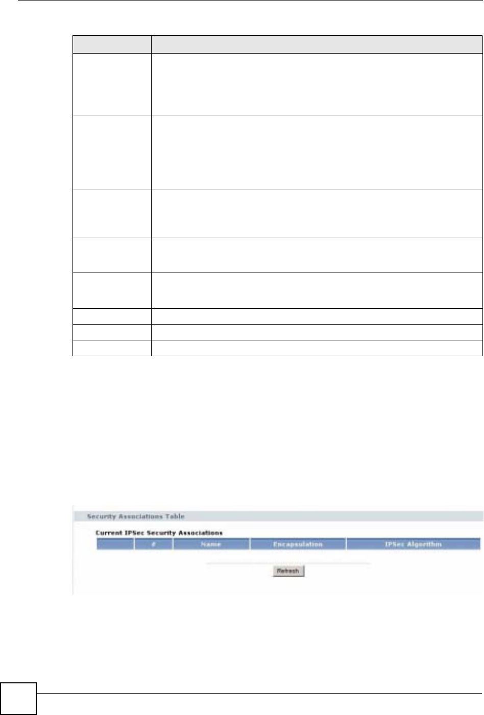
15.3 The SA Monitor Screen
In the web configurator, click Security > VPN > SA Monitor. Use this screen to display and
manage active VPN connections.
A Security Association (SA) is the group of security settings related to a specific VPN tunnel.
This screen displays active VPN connections. Use Refresh to display active VPN
connections.
Figure 109 Security > VPN > SA Monitor
IPSec Protocol Select the security protocols used for an SA.
Both AH and ESP increase processing requirements and communications latency
(delay).
If you select ESP here, you must select options from the Encryption Algorithm
and Authentication Algorithm fields (described below).
Encryption
Algorithm Select which key size and encryption algorithm to use in the IKE SA. Choices are:
DES - a 56-bit key with the DES encryption algorithm
3DES - a 168-bit key with the DES encryption algorithm
The NBG-460N and the remote IPSec router must use the same algorithms and
keys. Longer keys require more processing power, resulting in increased latency
and decreased throughput.
Encryption Key This field is applicable when you select ESP in the IPSec Protocol field above.
With DES, type a unique key 8 characters long. With 3DES, type a unique key 24
characters long. Any characters may be used, including spaces, but trailing
spaces are truncated.
Authentication
Algorithm Select which hash algorithm to use to authenticate packet data in the IPSec SA.
Choices are SHA1 and MD5.SHA1 is generally considered stronger than MD5,
but it is also slower.
Authentication
Key Type a unique authentication key to be used by IPSec if applicable. Enter 16
characters for MD5 authentication or 20 characters for SHA-1 authentication. Any
characters may be used, including spaces, but trailing spaces are truncated.
Apply Click Apply to save your changes back to the NBG-460N.
Reset Click Reset to begin configuring this screen afresh.
Cancel Click Cancel to exit the screen without making any changes.
Table 65 Security > VPN > Rule Setup: Manual (continued)
LABEL DESCRIPTION
Chapter 15 IPSec VPN
NBG-460N User’s Guide 185
The following table describes the labels in this screen.
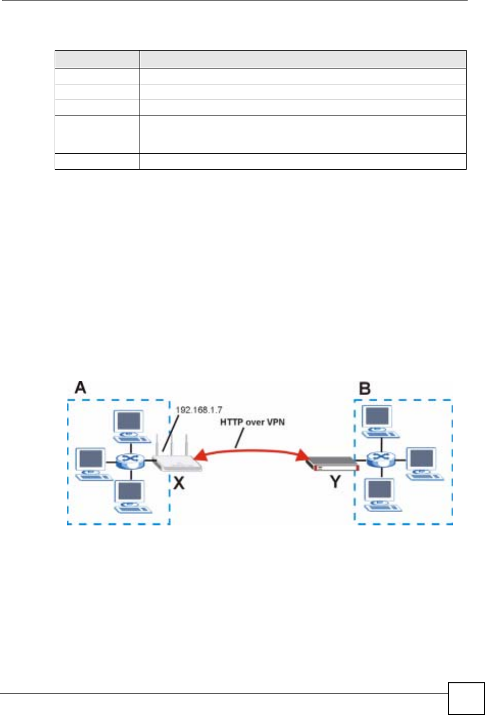
15.4 VPN and Remote Management
You can allow someone to use a service (like Telnet or HTTP) through a VPN tunnel to
manage the NBG-460N. One of the NBG-460N’s ports must be part of the VPN rule’s local
network. This can be the NBG-460N’s LAN port if you do not want to allow remote
management on the WAN port. You also have to configure remote management (REMOTE
MGMT) to allow management access for the service through the specific port.
In the following example, the VPN rule’s local network (A) includes the NBG-460N’s LAN
IP address of 192.168.1.7. Someone in the remote network (B) can use a service (like HTTP
for example) through the VPN tunnel to access the NBG-460N’s LAN interface. Remote
management must also be configured to allow HTTP access on the NBG-460N’s LAN
interface.
Figure 110 VPN for Remote Management Example
Table 66 Security > VPN > SA Monitor
LABEL DESCRIPTION
# This is the security association index number.
Name This field displays the identification name for this VPN policy.
Encapsulation This field displays Tunnel or Transport mode.
IPSec Algorithm This field displays the security protocols used for an SA.
Both AH and ESP increase NBG-460N processing requirements and
communications latency (delay).
Refresh Click Refresh to display the current active VPN connection(s).
Chapter 15 IPSec VPN
NBG-460N User’s Guide
186
15.5 IPSec VPN Technical Reference
IKE SA Proposal
The IKE SA proposal is used to identify the encryption algorithm, authentication algorithm,
and Diffie-Hellman (DH) key group that the NBG-460N and remote IPSec router use in the
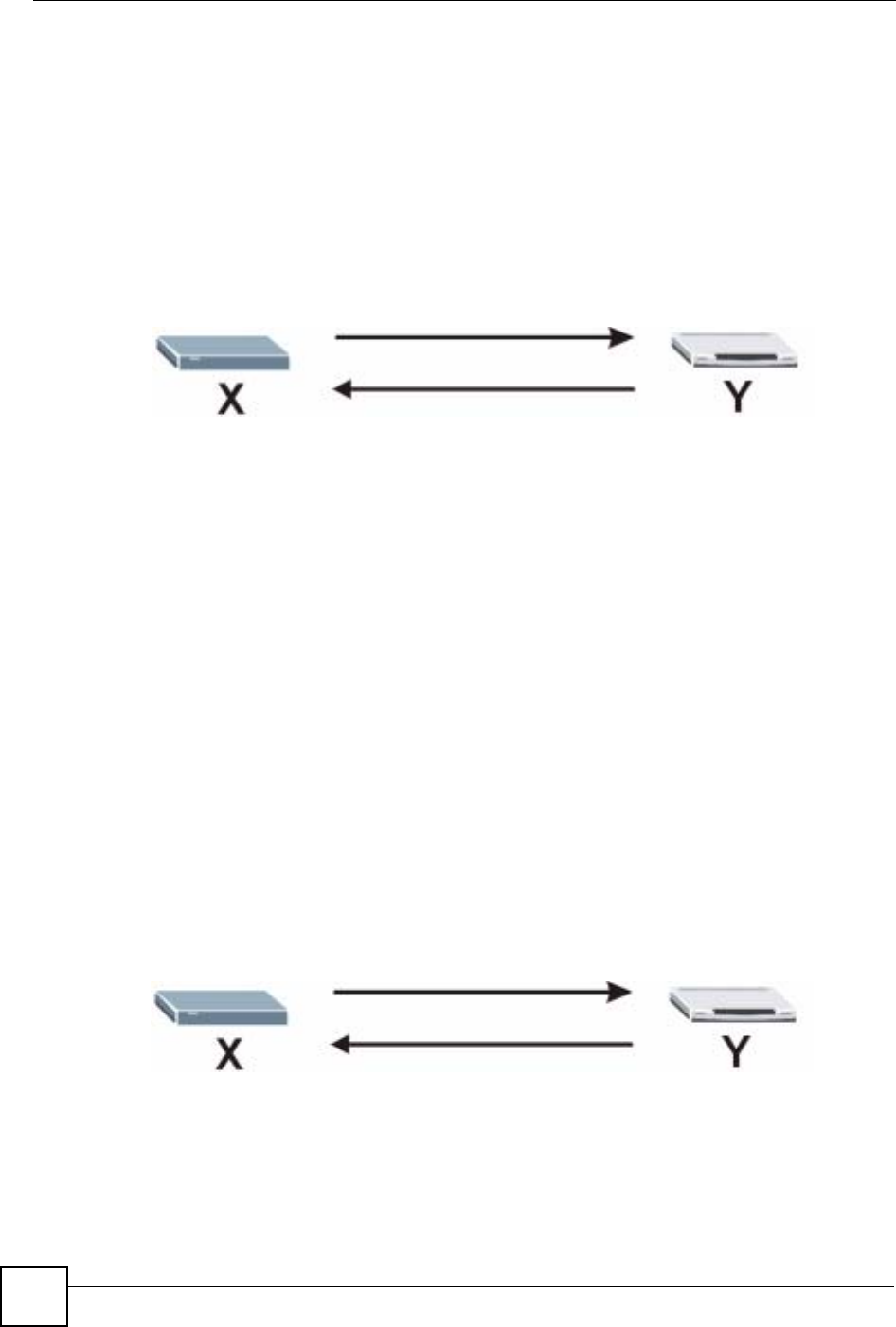
IKE SA. In main mode, this is done in steps 1 and 2, as illustrated below.
Figure 111 IKE SA: Main Negotiation Mode, Steps 1 - 2: IKE SA Proposal
The NBG-460N sends a proposal to the remote IPSec router. Each proposal consists of an
encryption algorithm, authentication algorithm, and DH key group that the NBG-460N wants
to use in the IKE SA. The remote IPSec router sends the accepted proposal back to the NBG-
460N. If the remote IPSec router rejects the proposal (for example, if the VPN tunnel is not
configured correctly), the NBG-460N and remote IPSec router cannot establish an IKE SA.
Note: Both routers must use the same encryption algorithm, authentication algorithm,
and DH key group.
See the field descriptions for information about specific encryption algorithms, authentication
algorithms, and DH key groups. See Diffie-Hellman (DH) Key Exchange on page 186 for
more information about DH key groups.
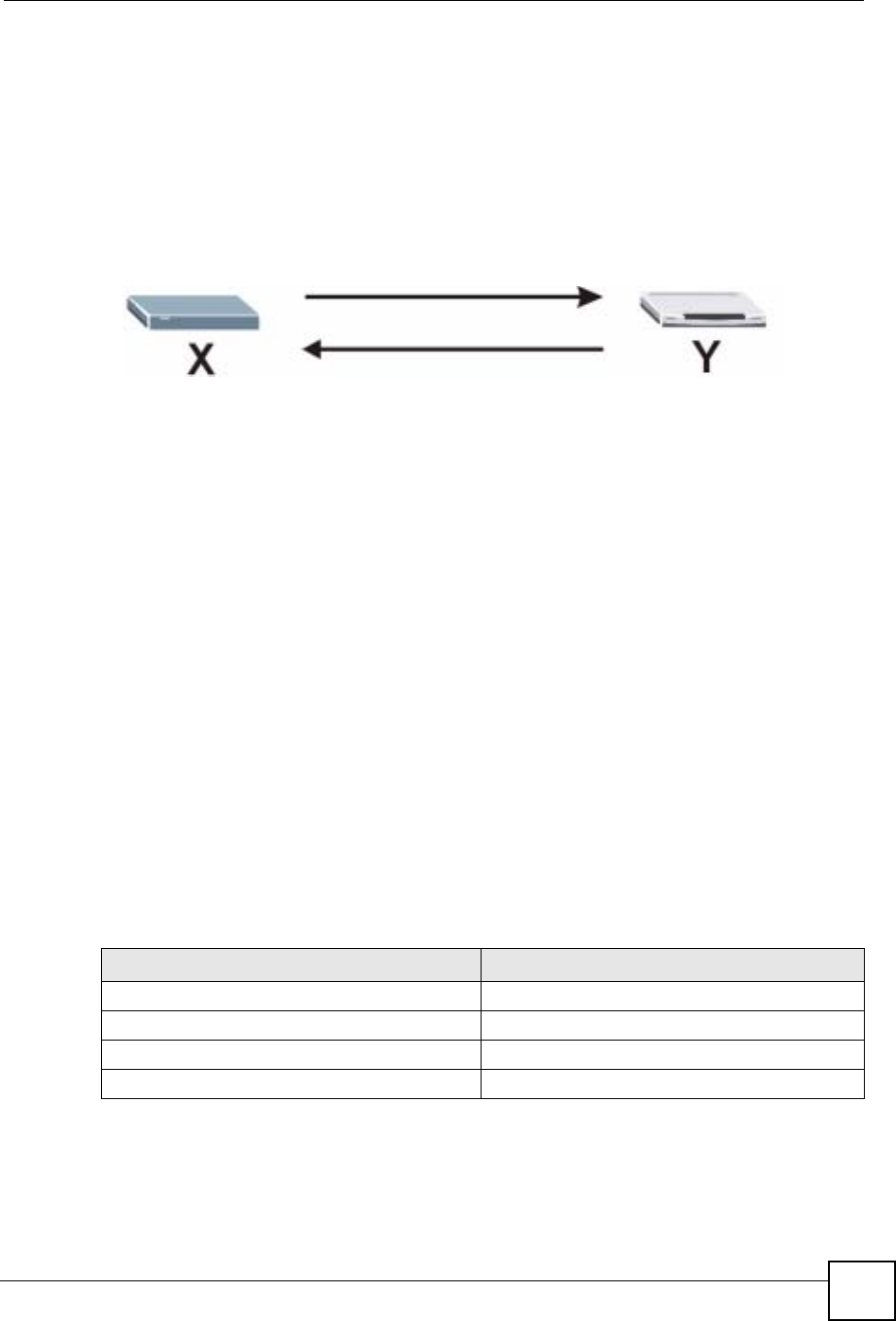
Diffie-Hellman (DH) Key Exchange
The NBG-460N and the remote IPSec router use a DH key exchange to establish a shared
secret, which is used to generate encryption keys for IKE SA and IPSec SA. In main mode, the
DH key exchange is done in steps 3 and 4, as illustrated below.
Figure 112 IKE SA: Main Negotiation Mode, Steps 3 - 4: DH Key Exchange
The DH key exchange is based on DH key groups. Each key group is a fixed number of bits
long. The longer the key, the more secure the encryption keys, but also the longer it takes to
encrypt and decrypt information. For example, DH2 keys (1024 bits) are more secure than
DH1 keys (768 bits), but DH2 encryption keys take longer to encrypt and decrypt.
1
2
3
4
Chapter 15 IPSec VPN
NBG-460N User’s Guide 187
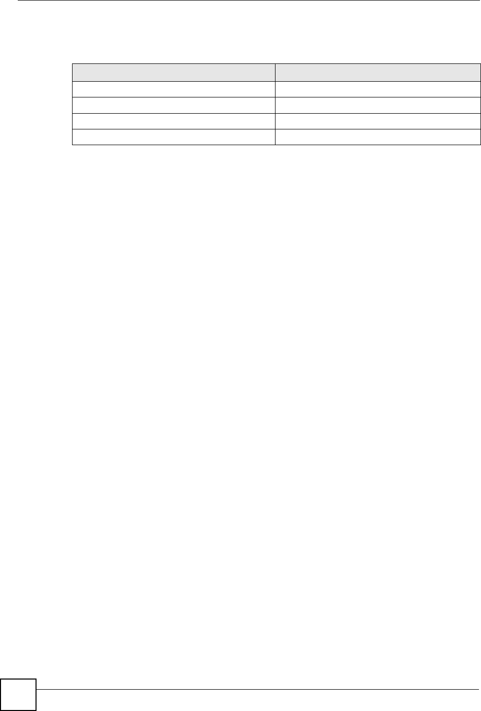
Authentication
Before the NBG-460N and remote IPSec router establish an IKE SA, they have to verify each
other’s identity. This process is based on pre-shared keys and router identities.
In main mode, the NBG-460N and remote IPSec router authenticate each other in steps 5 and
6, as illustrated below. Their identities are encrypted using the encryption algorithm and
encryption key the NBG-460N and remote IPSec router selected in previous steps.
Figure 113 IKE SA: Main Negotiation Mode, Steps 5 - 6: Authentication
The NBG-460N and remote IPSec router use a pre-shared key in the authentication process,
though it is not actually transmitted or exchanged.
Note: The NBG-460N and the remote IPSec router must use the same pre-shared
key.
Router identity consists of ID type and ID content. The ID type can be IP address, domain
name, or e-mail address, and the ID content is a specific IP address, domain name, or e-mail
address. The ID content is only used for identification; the IP address, domain name, or e-mail
address that you enter does not have to actually exist.
The NBG-460N and the remote IPSec router each has its own identity, so each one must store
two sets of information, one for itself and one for the other router. Local ID type and ID
content refers to the ID type and ID content that applies to the router itself, and peer ID type
and ID content refers to the ID type and ID content that applies to the other router in the IKE
SA.
Note: The NBG-460N’s local and peer ID type and ID content must match the remote
IPSec router’s peer and local ID type and ID content, respectively.
In the following example, the ID type and content match so the NBG-460N and the remote
IPSec router authenticate each other successfully.
Table 67 VPN Example: Matching ID Type and Content
NBG-460N REMOTE IPSEC ROUTER
Local ID type: E-mail Local ID type: IP
Local ID content: tom@yourcompany.com Local ID content: 1.1.1.2
Peer ID type: IP Peer ID type: E-mail
Peer ID content: 1.1.1.2 Peer ID content: tom@yourcompany.com
5
6
Chapter 15 IPSec VPN
NBG-460N User’s Guide
188
In the following example, the ID type and content do not match so the authentication fails and
the NBG-460N and the remote IPSec router cannot establish an IKE SA.
Negotiation Mode
There are two negotiation modes: main mode and aggressive mode. Main mode provides
better security, while aggressive mode is faster.
Main mode takes six steps to establish an IKE SA.
Steps 1-2: The NBG-460N sends its proposals to the remote IPSec router. The remote IPSec
router selects an acceptable proposal and sends it back to the NBG-460N.
Steps 3-4: The NBG-460N and the remote IPSec router participate in a Diffie-Hellman key
exchange, based on the accepted DH key group, to establish a shared secret.
Steps 5-6: Finally, the NBG-460N and the remote IPSec router generate an encryption key
from the shared secret, encrypt their identities, and exchange their encrypted identity
information for authentication.
In contrast, aggressive mode only takes three steps to establish an IKE SA.
Step 1: The NBG-460N sends its proposals to the remote IPSec router. It also starts the Diffie-
Hellman key exchange and sends its (unencrypted) identity to the remote IPSec router for
authentication.
Step 2: The remote IPSec router selects an acceptable proposal and sends it back to the NBG-
460N. It also finishes the Diffie-Hellman key exchange, authenticates the NBG-460N, and
sends its (unencrypted) identity to the NBG-460N for authentication.
Step 3: The NBG-460N authenticates the remote IPSec router and confirms that the IKE SA is
established.
Aggressive mode does not provide as much security as main mode because the identity of the
NBG-460N and the identity of the remote IPSec router are not encrypted. It is usually used
when the address of the initiator is not known by the responder and both parties want to use
pre-shared keys for authentication (for example, telecommuters).
VPN, NAT, and NAT Traversal
In the following example, there is another router (A) between router X and router Y.
Table 68 VPN Example: Mismatching ID Type and Content
NBG-460N REMOTE IPSEC ROUTER
Local ID type: E-mail Local ID type: IP
Local ID content: tom@yourcompany.com Local ID content: 1.1.1.2
Peer ID type: IP Peer ID type: E-mail
Peer ID content: 1.1.1.15 Peer ID content: tom@yourcompany.com
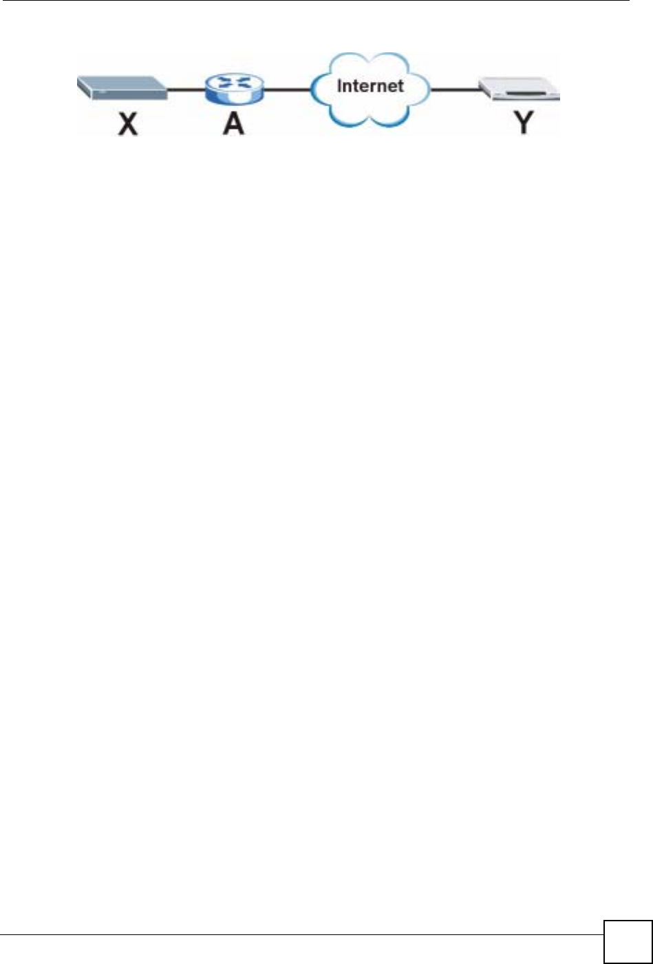
Chapter 15 IPSec VPN
NBG-460N User’s Guide 189
Figure 114 VPN/NAT Example
If router A does NAT, it might change the IP addresses, port numbers, or both. If router X and
router Y try to establish a VPN tunnel, the authentication fails because it depends on this
information. The routers cannot establish a VPN tunnel.
Most routers like router A now have an IPSec pass-through feature. This feature helps router A
recognize VPN packets and route them appropriately. If router A has this feature, router X and
router Y can establish a VPN tunnel as long as the IPSec protocol is ESP. (See IPSec Protocol
on page 189 for more information about active protocols.)
If router A does not have an IPSec pass-through or if the IPSec protocol is AH, you can solve
this problem by enabling NAT traversal. In NAT traversal, router X and router Y add an extra
header to the IKE SA and IPSec SA packets. If you configure router A to forward these
packets unchanged, router X and router Y can establish a VPN tunnel.
You have to do the following things to set up NAT traversal.
• Enable NAT traversal on the NBG-460N and remote IPSec router.
• Configure the NAT router to forward packets with the extra header unchanged.
The extra header may be UDP port 500 or UDP port 4500, depending on the standard(s) the
NBG-460N and remote IPSec router support.
IPSec Protocol
The IPSec protocol controls the format of each packet. It also specifies how much of each
packet is protected by the encryption and authentication algorithms. IPSec VPN includes two
IPSec protocols, AH (Authentication Header, RFC 2402) and ESP (Encapsulating Security
Payload, RFC 2406).
Note: The NBG-460N and remote IPSec router must use the same IPSec protocol.
Usually, you should select ESP. AH does not support encryption, and ESP is more suitable
with NAT.
Encapsulation
There are two ways to encapsulate packets. Usually, you should use tunnel mode because it is
more secure. Transport mode is only used when the IPSec SA is used for communication
between the NBG-460N and remote IPSec router (for example, for remote management), not
between computers on the local and remote networks.
Note: The NBG-460N and remote IPSec router must use the same encapsulation.
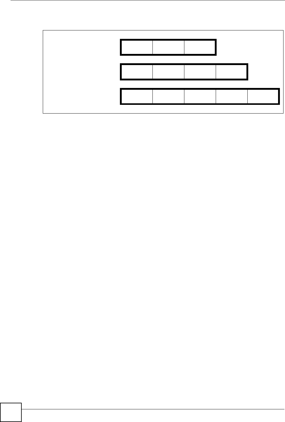
Chapter 15 IPSec VPN
NBG-460N User’s Guide
190
These modes are illustrated below.
In tunnel mode, the NBG-460N uses the IPSec protocol to encapsulate the entire IP packet. As
a result, there are two IP headers:
• Outside header: The outside IP header contains the IP address of the NBG-460N or remote
IPSec router, whichever is the destination.
• Inside header: The inside IP header contains the IP address of the computer behind the
NBG-460N or remote IPSec router. The header for the IPSec protocol (AH or ESP)
appears between the IP headers.
In transport mode, the encapsulation depends on the IPSec protocol. With AH, the NBG-460N
includes part of the original IP header when it encapsulates the packet. With ESP, however,
the NBG-460N does not include the IP header when it encapsulates the packet, so it is not
possible to verify the integrity of the source IP address.
IPSec SA Proposal and Perfect Forward Secrecy
An IPSec SA proposal is similar to an IKE SA proposal (see IKE SA Proposal on page 186),
except that you also have the choice whether or not the NBG-460N and remote IPSec router
perform a new DH key exchange every time an IPSec SA is established. This is called Perfect
Forward Secrecy (PFS).
If you enable PFS, the NBG-460N and remote IPSec router perform a DH key exchange every
time an IPSec SA is established, changing the root key from which encryption keys are
generated. As a result, if one encryption key is compromised, other encryption keys remain
secure.
If you do not enable PFS, the NBG-460N and remote IPSec router use the same root key that
was generated when the IKE SA was established to generate encryption keys.
The DH key exchange is time-consuming and may be unnecessary for data that does not
require such security.
Figure 115 VPN: Transport and Tunnel Mode Encapsulation
Original Packet IP Header TCP
Header Data
Transport Mode Packet IP Header AH/ESP
Header TCP
Header Data
Tunnel Mode Packet IP Header AH/ESP
Header IP Header TCP
Header Data

Chapter 15 IPSec VPN
NBG-460N User’s Guide 191
Additional IPSec VPN Topics
This section discusses other IPSec VPN topics that apply to either IKE SAs or IPSec SAs or
both. Relationships between the topics are also highlighted.
SA Life Time
SAs have a lifetime that specifies how long the SA lasts until it times out. When an SA times
out, the NBG-460N automatically renegotiates the SA in the following situations:
• There is traffic when the SA life time expires
• The IPSec SA is configured on the NBG-460N as nailed up (see below)
Otherwise, the NBG-460N must re-negotiate the SA the next time someone wants to send
traffic.
Note: If the IKE SA times out while an IPSec SA is connected, the IPSec SA stays
connected.
An IPSec SA can be set to keep alive Normally, the NBG-460N drops the IPSec SA when the
life time expires or after two minutes of outbound traffic with no inbound traffic. If you set the
IPSec SA to keep alive , the NBG-460N automatically renegotiates the IPSec SA when the SA
life time expires, and it does not drop the IPSec SA if there is no inbound traffic.
Note: The SA life time and keep alive settings only apply if the rule identifies the
remote IPSec router by a static IP address or a domain name. If the Secure
Gateway Address field is set to 0.0.0.0, the NBG-460N cannot initiate the
tunnel (and cannot renegotiate the SA).
Encryption and Authentication Algorithms
In most NBG-460Ns, you can select one of the following encryption algorithms for each
proposal. The encryption algorithms are listed here in order from weakest to strongest.
• Data Encryption Standard (DES) is a widely used (but breakable) method of data
encryption. It applies a 56-bit key to each 64-bit block of data.
• Triple DES (3DES) is a variant of DES. It iterates three times with three separate keys,
effectively tripling the strength of DES.
You can select one of the following authentication algorithms for each proposal. The
algorithms are listed here in order from weakest to strongest.
• MD5 (Message Digest 5) produces a 128-bit digest to authenticate packet data.
• SHA1 (Secure Hash Algorithm) produces a 160-bit digest to authenticate packet data.
Private DNS Server
In cases where you want to use domain names to access Intranet servers on a remote private
network that has a DNS server, you must identify that DNS server. You cannot use DNS
servers on the LAN or from the ISP since these DNS servers cannot resolve domain names to
private IP addresses on the remote private network.
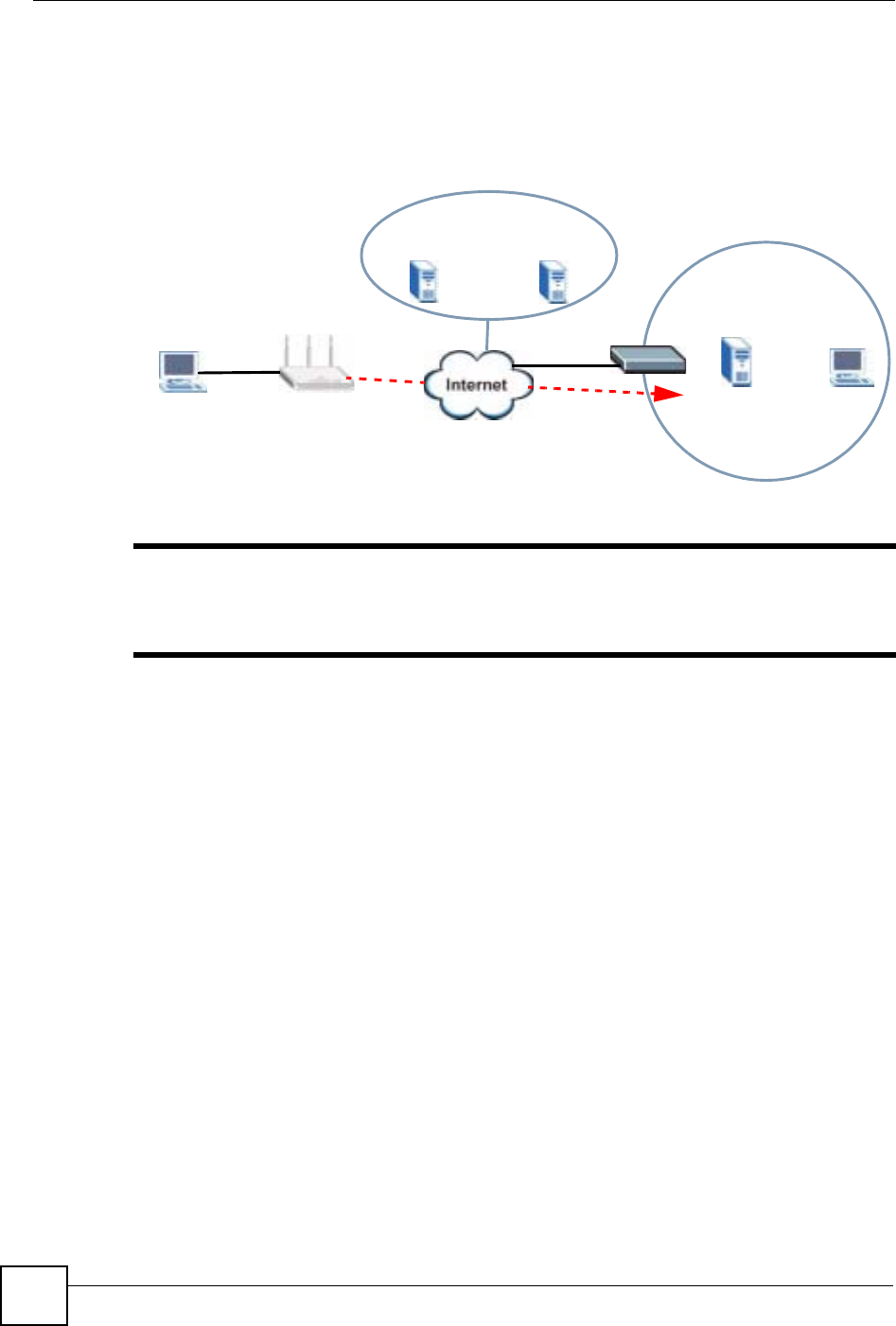
Chapter 15 IPSec VPN
NBG-460N User’s Guide
192
The following figure depicts an example where one VPN tunnel is created from an NBG-460N
at branch office (B) to headquarters (HQ). In order to access computers that use private
domain names on the HQ network, the NBG-460N at B uses the Intranet DNS server in
headquarters.
Figure 116 Private DNS Server Example
"If you do not specify an Intranet DNS server on the remote network, then the
VPN host must use IP addresses to access the computers on the remote
private network.
HQ
10.1.1.1/200
Intranet DNS
10.1.1.10
ISP
DNS Servers
212.54.64.170 212.54.64.171
LAN
DNS: 212.51.61.170
212.54.64.171
B

193
PART IV
Management
Static Route Screens (195)
Bandwidth Management (199)
Remote Management (209)
Universal Plug-and-Play (UPnP) (215)

194
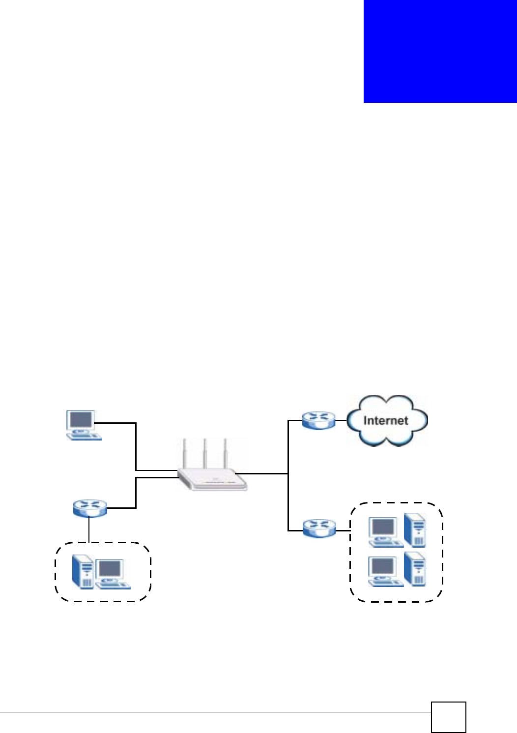
NBG-460N User’s Guide 195
CHAPTER 16
Static Route Screens
This chapter shows you how to configure static routes for your NBG-460N.
16.1 Static Route Overview
The NBG-460N usually uses the default gateway to route outbound traffic from computers on
the LAN to the Internet. To have the NBG-460N send data to devices not reachable through
the default gateway, use static routes.
For example, the next figure shows a computer (A) connected to the NBG-460N’s LAN
interface. The NBG-460N routes most traffic from Ato the Internet through the NBG-460N’s
default gateway (R1). You create one static route to connect to services offered by your ISP
behind router R2. You create another static route to communicate with a separate network
behind a router R3 connected to the LAN.
Figure 117 Example of Static Routing Topology
16.2 IP Static Route Screen
Click Management > Static Route to open the IP Static Route screen. The following screen
displays.
WAN
R1
R2
A
R3
LAN
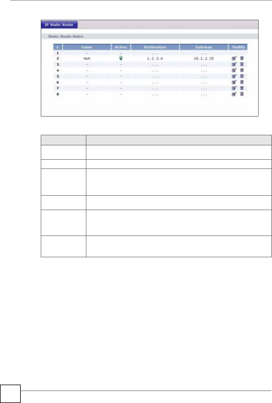
Chapter 16 Static Route Screens
NBG-460N User’s Guide
196
Figure 118 Management > Static Route > IP Static Route
The following table describes the labels in this screen.
16.2.1 Static Route Setup Screen
To edit a static route, click the edit icon under Modify. The following screen displays. Fill in
the required information for each static route.
Table 69 Management > Static Route > IP Static Route
LABEL DESCRIPTION
#This is the index number of an individual static route. The first entry is for the
default route and not editable.
Name This is the name that describes or identifies this route.
Active This icon is turned on when this static route is active.
Click the Edit icon under Modify and select the Active checkbox in the Static
Route Setup screen to enable the static route. Clear the checkbox to disable this
static route without having to delete the entry.
Destination This parameter specifies the IP network address of the final destination. Routing
is always based on network number.
Gateway This is the IP address of the gateway. The gateway is an immediate neighbor of
your NBG-460N that will forward the packet to the destination. On the LAN, the
gateway must be a router on the same segment as your NBG-460N; over the
WAN, the gateway must be the IP address of one of the remote nodes.
Modify Click the Edit icon to open the static route setup screen. Modify a static route or
create a new static route in the Static Route Setup screen.
Click the Remove icon to delete a static route.
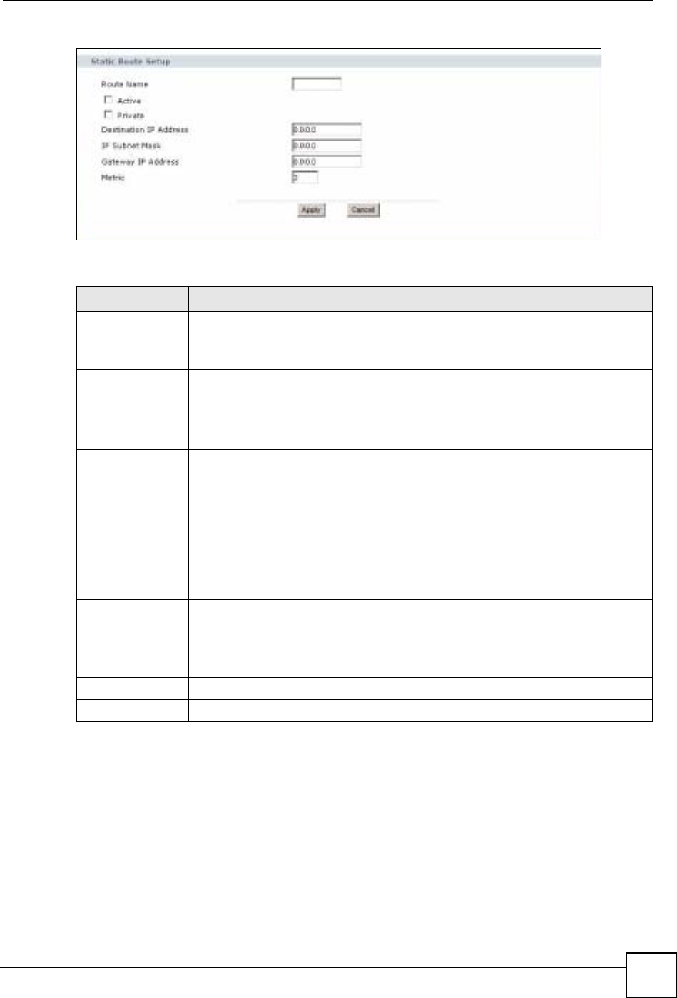
Chapter 16 Static Route Screens
NBG-460N User’s Guide 197
Figure 119 Management > Static Route > IP Static Route: Static Route Setup
The following table describes the labels in this screen.
Table 70 Management > Static Route > IP Static Route: Static Route Setup
LABEL DESCRIPTION
Route Name Enter the name of the IP static route. Leave this field blank to delete this static
route.
Active This field allows you to activate/deactivate this static route.
Private This parameter determines if the NBG-460N will include this route to a remote
node in its RIP broadcasts.
Select this check box to keep this route private and not included in RIP
broadcasts. Clear this checkbox to propagate this route to other hosts through RIP
broadcasts.
Destination IP
Address This parameter specifies the IP network address of the final destination. Routing is
always based on network number. If you need to specify a route to a single host,
use a subnet mask of 255.255.255.255 in the subnet mask field to force the
network number to be identical to the host ID.
IP Subnet Mask Enter the IP subnet mask here.
Gateway IP
Address Enter the IP address of the gateway. The gateway is an immediate neighbor of
your NBG-460N that will forward the packet to the destination. On the LAN, the
gateway must be a router on the same segment as your NBG-460N; over the
WAN, the gateway must be the IP address of one of the Remote Nodes.
Metric Metric represents the “cost” of transmission for routing purposes. IP routing uses
hop count as the measurement of cost, with a minimum of 1 for directly connected
networks. Enter a number that approximates the cost for this link. The number
need not be precise, but it must be between 1 and 15. In practice, 2 or 3 is usually
a good number.
Apply Click Apply to save your changes back to the NBG-460N.
Cancel Click Cancel to return to the previous screen and not save your changes.

Chapter 16 Static Route Screens
NBG-460N User’s Guide
198

NBG-460N User’s Guide 199
CHAPTER 17
Bandwidth Management
This chapter contains information about configuring bandwidth management, editing rules and
viewing the NBG-460N’s bandwidth management logs.
17.1 Bandwidth Management Overview
ZyXEL’s Bandwidth Management allows you to specify bandwidth management rules based
on an application and/or subnet. You can allocate specific amounts of bandwidth capacity
(bandwidth budgets) to different bandwidth rules.
The NBG-460N applies bandwidth management to traffic that it forwards out through an
interface. The NBG-460N does not control the bandwidth of traffic that comes into an
interface.
Bandwidth management applies to all traffic flowing out of the router, regardless of the
traffic's source.
Traffic redirect or IP alias may cause LAN-to-LAN traffic to pass through the NBG-460N and
be managed by bandwidth management.
• The sum of the bandwidth allotments that apply to the WAN interface (LAN to WAN,
WLAN to WAN, WAN to WAN / NBG-460N) must be less than or equal to the
Upstream Bandwidth that you configure in the Bandwidth Management Advanced
screen.
• The sum of the bandwidth allotments that apply to the LAN port (WAN to LAN, WLAN
to LAN, LAN to LAN / NBG-460N) must be less than or equal to 100,000 kbps (you
cannot configure the bandwidth budget for the LAN port).
• The sum of the bandwidth allotments that apply to the WLAN port (LAN to WLAN,
WAN to WLAN, WLAN to WLAN / NBG-460N) must be less than or equal to 54,000
kbps (you cannot configure the bandwidth budget for the WLAN port).
17.2 Application-based Bandwidth Management
You can create bandwidth classes based on individual applications (like VoIP, Web, FTP, E-
mail and Video for example).
17.3 Subnet-based Bandwidth Management
You can create bandwidth classes based on subnets.
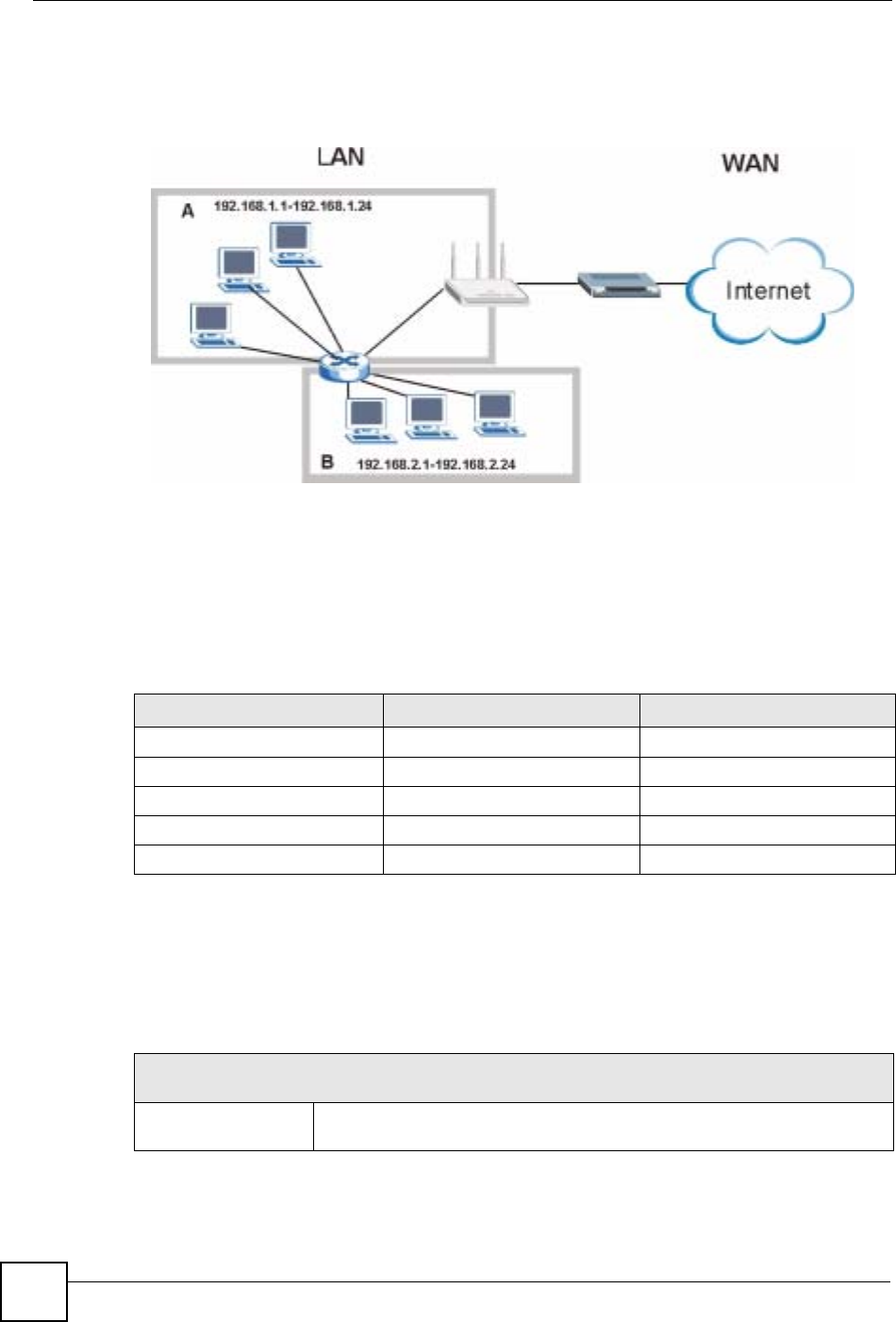
Chapter 17 Bandwidth Management
NBG-460N User’s Guide
200
The following figure shows LAN subnets. You could configure one bandwidth class for
subnet A and another for subnet B.
Figure 120 Subnet-based Bandwidth Management Example
17.4 Application and Subnet-based Bandwidth Management
You could also create bandwidth classes based on a combination of a subnet and an
application. The following example table shows bandwidth allocations for application specific
traffic from separate LAN subnets.
17.5 Bandwidth Management Priorities
The following table describes the priorities that you can apply to traffic that the NBG-460N
forwards out through an interface.
Table 71 Application and Subnet-based Bandwidth Management Example
TRAFFIC TYPE FROM SUBNET A FROM SUBNET B
VoIP 64 Kbps 64 Kbps
Web 64 Kbps 64 Kbps
FTP 64 Kbps 64 Kbps
E-mail 64 Kbps 64 Kbps
Video 64 Kbps 64 Kbps
Table 72 Bandwidth Management Priorities
PRIORITY LEVELS: TRAFFIC WITH A HIGHER PRIORITY GETS THROUGH FASTER WHILE
TRAFFIC WITH A LOWER PRIORITY IS DROPPED IF THE NETWORK IS CONGESTED.
High Typically used for voice traffic or video that is especially sensitive to jitter (jitter
is the variations in delay).
Chapter 17 Bandwidth Management
NBG-460N User’s Guide 201
17.6 Predefined Bandwidth Management Services
The following is a description of the services that you can select and to which you can apply
media bandwidth management using the wizard screens.
17.6.1 Services and Port Numbers
See Appendix F on page 321 for commonly used services and port numbers.
Mid Typically used for “excellent effort” or better than best effort and would include
important business traffic that can tolerate some delay.
Low This is typically used for non-critical “background” traffic such as bulk
transfers that are allowed but that should not affect other applications and
users.
Table 72 Bandwidth Management Priorities
PRIORITY LEVELS: TRAFFIC WITH A HIGHER PRIORITY GETS THROUGH FASTER WHILE
TRAFFIC WITH A LOWER PRIORITY IS DROPPED IF THE NETWORK IS CONGESTED.
Table 73 Media Bandwidth Management Setup: Services
SERVICE DESCRIPTION
Xbox Live This is Microsoft’s online gaming service that lets you play multiplayer Xbox
games on the Internet via broadband technology. Xbox Live uses port 3074.
VoIP (SIP) Sending voice signals over the Internet is called Voice over IP or VoIP. Session
Initiated Protocol (SIP) is an internationally recognized standard for implementing
VoIP. SIP is an application-layer control (signaling) protocol that handles the
setting up, altering and tearing down of voice and multimedia sessions over the
Internet.
SIP is transported primarily over UDP but can also be transported over TCP,
using the default port number 5060.
FTP File Transfer Program enables fast transfer of files, including large files that may
not be possible by e-mail. FTP uses port number 21.
E-Mail Electronic mail consists of messages sent through a computer network to specific
groups or individuals. Here are some default ports for e-mail:
POP3 - port 110
IMAP - port 143
SMTP - port 25
HTTP - port 80
BitTorrent BitTorrent is a free P2P (peer-to-peer) sharing tool allowing you to distribute large
software and media files using ports 6881 to 6889. BitTorrent requires you to
search for a file with a searching engine yourself. It distributes files by corporation
and trading, that is, the client downloads the file in small pieces and share the
pieces with other peers to get other half of the file.
MSN Webcam MSN messenger allows you to chat online and send instant messages. If you use
MSN messenger and also have a webcam, you can send your image/photo in
real-time along with messages
WWW The World Wide Web (WWW) is an Internet system to distribute graphical, hyper-
linked information, based on Hyper Text Transfer Protocol (HTTP) - a client/server
protocol for the World Wide Web. The Web is not synonymous with the Internet;
rather, it is just one service on the Internet. Other services on the Internet include
Internet Relay Chat and Newsgroups. The Web is accessed through use of a
browser.
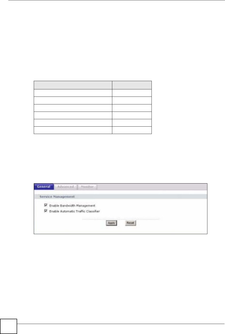
Chapter 17 Bandwidth Management
NBG-460N User’s Guide
202
17.7 Default Bandwidth Management Classes and Priorities
If you enable bandwidth management but do not configure a rule for critical traffic like VoIP,
the voice traffic may then get delayed due to insufficient bandwidth. With the automatic traffic
classifier feature activated, the NBG-460N automatically assigns a default bandwidth
management class and priority to traffic that does not match any of the user-defined rules. The
traffic is classified based on the traffic type. Real-time traffic always gets higher priority over
other traffic.
The following table shows you the priorities between the three default classes (AutoClass_H,
AutoClass_M and Default Class) and user-defined rules. 6 is the highest priority.
17.8 Bandwidth Management General Configuration
Click Management > Bandwidth MGMT to open the bandwidth management General
screen.
Figure 121 Management > Bandwidth MGMT > General
Table 74 Bandwidth Management Priority with Default Classes
CLASS TYPE PRIORITY
User-defined with high priority 6
AutoClass_H 5
User-defined with medium priority 4
AutoClass_M 3
User-defined with low priority 2
Default Class 1
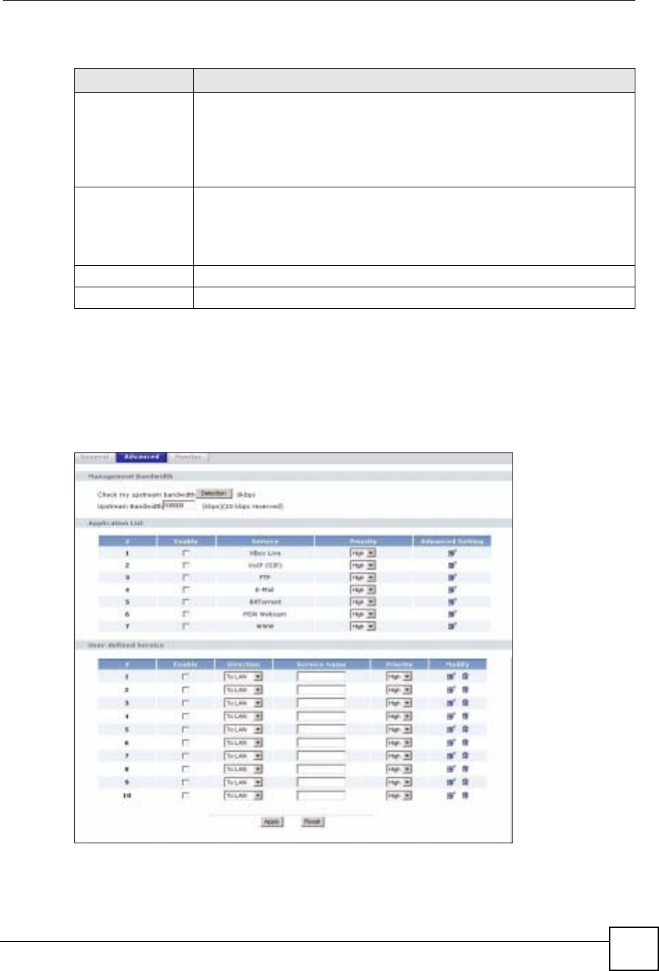
Chapter 17 Bandwidth Management
NBG-460N User’s Guide 203
The following table describes the labels in this screen.
17.9 Bandwidth Management Advanced Configuration
Click Management > Bandwidth MGMT > Advanced to open the bandwidth management
Advanced screen.
Figure 122 Management > Bandwidth MGMT > Advanced
Table 75 Management > Bandwidth MGMT > General
LABEL DESCRIPTION
Enable Bandwidth
Management Select this check box to have the NBG-460N apply bandwidth management.
Enable bandwidth management to give traffic that matches a bandwidth rule
priority over traffic that does not match a bandwidth rule.
Enabling bandwidth management also allows you to control the maximum or
minimum amounts of bandwidth that can be used by traffic that matches a
bandwidth rule.
Enable Automatic
Traffic Classifier This field is only applicable when you select the Enable Bandwidth
Management check box.
Select this check box to have the NBG-460N base on the default bandwidth
classes to apply bandwidth management. Real-time packets, such as VoIP
traffic always get higher priority.
Apply Click Apply to save your customized settings.
Reset Click Reset to begin configuring this screen afresh.

Chapter 17 Bandwidth Management
NBG-460N User’s Guide
204
The following table describes the labels in this screen.
Table 76 Management > Bandwidth MGMT > Advanced
LABEL DESCRIPTION
Check my
upstream
bandwidth
Click the Detection button to check the size of your upstream bandwidth.
Upstream
Bandwidth (kbps) Enter the amount of bandwidth in kbps (2 to 100,000) that you want to allocate for
traffic. 20 kbps to 20,000 kbps is recommended.
The recommendation is to set this speed to be equal to or less than the speed of
the broadband device connected to the WAN port. For example, set the speed to
1000 Kbps (or less) if the broadband device connected to the WAN port has an
upstream speed of 1000 Kbps.
Application List Use this table to allocate specific amounts of bandwidth based on the pre-defined
service.
#This is the number of an individual bandwidth management rule.
Enable Select this check box to have the NBG-460N apply this bandwidth management
rule.
Service This is the name of the service.
Priority Select a priority from the drop down list box. Choose High,Mid or Low.
Advanced Setting Click the Edit icon to open the Rule Configuration screen where you can modify
the rule.
User-defined
Service Use this table to allocate specific amounts of bandwidth to specific applications
and/or subnets.
#This is the number of an individual bandwidth management rule.
Enable Select this check box to have the NBG-460N apply this bandwidth management
rule.
Direction Select To LAN to apply bandwidth management to traffic that the NBG-460N
forwards to the LAN.
Select To WAN to apply bandwidth management to traffic that the NBG-460N
forwards to the WAN.
Select To WLAN to apply bandwidth management to traffic that the NBG-460N
forwards to the WLAN.
Service Name Enter a descriptive name of up to 19 alphanumeric characters, including spaces.
Priority Select a priority from the drop down list box. Choose High,Mid or Low.
Modify Click the Edit icon to open the Rule Configuration screen. Modify an existing rule
or create a new rule in the Rule Configuration screen. See Section 17.9.2 on
page 205 for more information.
Click the Remove icon to delete a rule.
Apply Click Apply to save your customized settings.
Reset Click Reset to begin configuring this screen afresh.
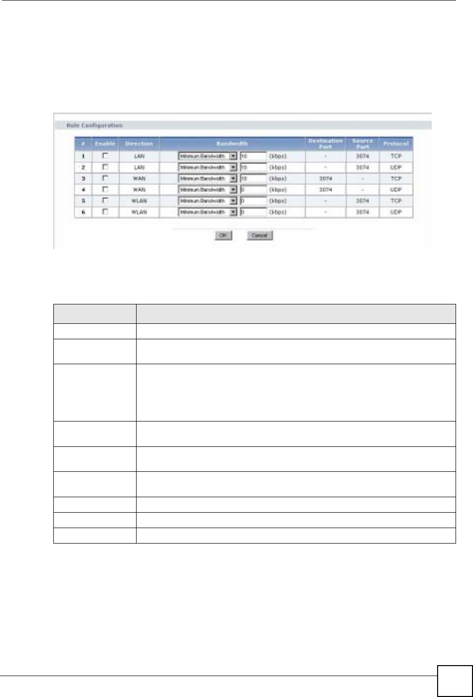
Chapter 17 Bandwidth Management
NBG-460N User’s Guide 205
17.9.1 Rule Configuration with the Pre-defined Service
To edit a bandwidth management rule for the pre-defined service in the NBG-460N, click the
Edit icon in the Application List table of the Advanced screen. The following screen
displays.
Figure 123 Bandwidth Management Rule Configuration: Pre-defined Service
The following table describes the labels in this screen.
17.9.2 Rule Configuration: User Defined Service Rule Configuration
If you want to edit a bandwidth management rule for other applications and/or subnets, click
the Edit icon in the User-defined Service table of the Advanced screen. The following screen
displays.
Table 77 Bandwidth Management Rule Configuration: Pre-defined Service
LABEL DESCRIPTION
#This is the number of an individual bandwidth management rule.
Enable Select an interface’s check box to enable bandwidth management on that
interface.
Direction These read-only labels represent the physical interfaces. Bandwidth management
applies to all traffic flowing out of the router through the interface, regardless of
the traffic’s source.
Traffic redirect or IP alias may cause LAN-to-LAN traffic to pass through the NBG-
460N and be managed by bandwidth management.
Bandwidth Select Maximum Bandwidth or Minimum Bandwidth and specify the maximum
or minimum bandwidth allowed for the rule in kilobits per second.
Destination Port This is the port number of the destination. See Appendix F on page 321 for some
common services and port numbers.
Source Port This is the port number of the source. See Appendix F on page 321 for some
common services and port numbers.
Protocol This is the protocol (TCP or UDP) used for the service.
OK Click OK to save your customized settings.
Cancel Click Cancel to exit this screen without saving.
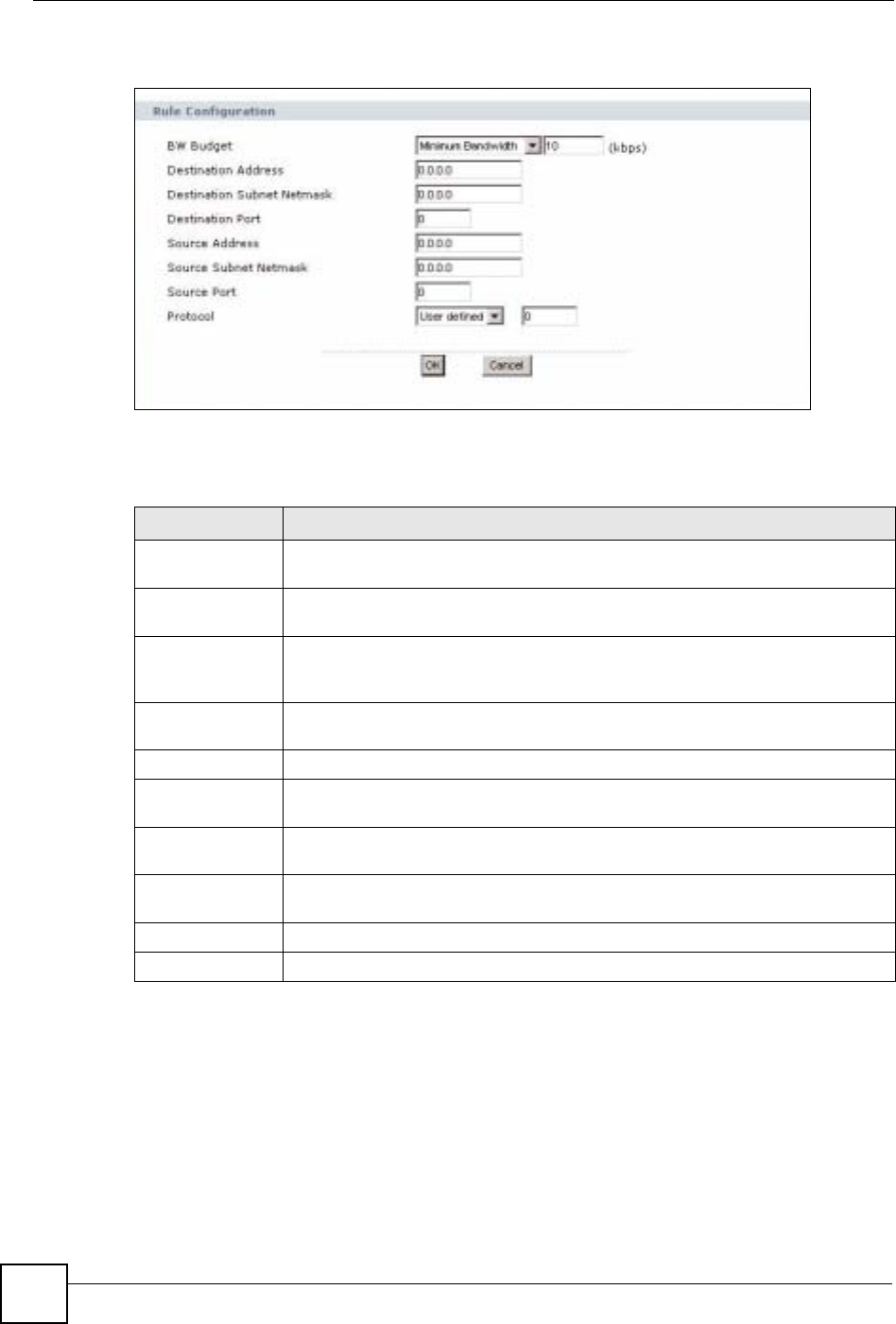
Chapter 17 Bandwidth Management
NBG-460N User’s Guide
206
Figure 124 Management > Bandwidth MGMT > Advanced: User-defined Service Rule
Configuration
The following table describes the labels in this screen
Table 78 Management > Bandwidth MGMT > Advanced: User-defined Service Rule
Configuration
17.10 Bandwidth Management Monitor
Click Management > Bandwidth MGMT > Monitor to open the bandwidth management
Monitor screen. View the bandwidth usage of the WAN configured bandwidth rules. This is
also shown as bandwidth usage over the bandwidth budget for each rule. The gray section of
the bar represents the percentage of unused bandwidth and the blue color represents the
percentage of bandwidth in use.
LABEL DESCRIPTION
BW Budget Select Maximum Bandwidth or Minimum Bandwidth and specify the maximum
or minimum bandwidth allowed for the rule in kilobits per second.
Destination
Address Enter the destination IP address in dotted decimal notation.
Destination
Subnet Netmask Enter the destination subnet mask. This field is N/A if you do not specify a
Destination Address. Refer to the appendices for more information on IP
subnetting.
Destination Port Enter the port number of the destination. See Appendix F on page 321 for some
common services and port numbers.
Source Address Enter the source IP address in dotted decimal notation.
Source Subnet
Netmask Enter the destination subnet mask. This field is N/A if you do not specify a Source
Address. Refer to the appendices for more information on IP subnetting.
Source Port Enter the port number of the source. See Appendix F on page 321 for some
common services and port numbers.
Protocol Select the protocol (TCP or UDP) or select User defined and enter the protocol
(service type) number.
OK Click OK to save your customized settings.
Cancel Click Cancel to exit this screen without saving.
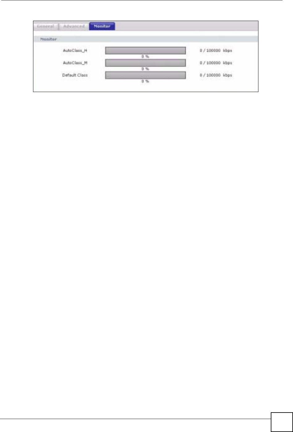
Chapter 17 Bandwidth Management
NBG-460N User’s Guide 207
Figure 125 Management > Bandwidth MGMT > Monitor

Chapter 17 Bandwidth Management
NBG-460N User’s Guide
208

NBG-460N User’s Guide 209
CHAPTER 18
Remote Management
This chapter provides information on the Remote Management screens.
18.1 Remote Management Overview
Remote management allows you to determine which services/protocols can access which
NBG-460N interface (if any) from which computers.
"When you configure remote management to allow management from the
WAN, you still need to configure a firewall rule to allow access. See the firewall
chapters for details on configuring firewall rules.
You may manage your NBG-460N from a remote location via:
"When you choose WAN or LAN & WAN, you still need to configure a firewall
rule to allow access.
To disable remote management of a service, select Disable in the corresponding Server
Access field.
You may only have one remote management session running at a time. The NBG-460N
automatically disconnects a remote management session of lower priority when another
remote management session of higher priority starts. The priorities for the different types of
remote management sessions are as follows.
1Telnet
2HTTP
18.1.1 Remote Management Limitations
Remote management over LAN or WAN will not work when:
• Internet (WAN only) • ALL (LAN and WAN)
• LAN only • Neither (Disable).
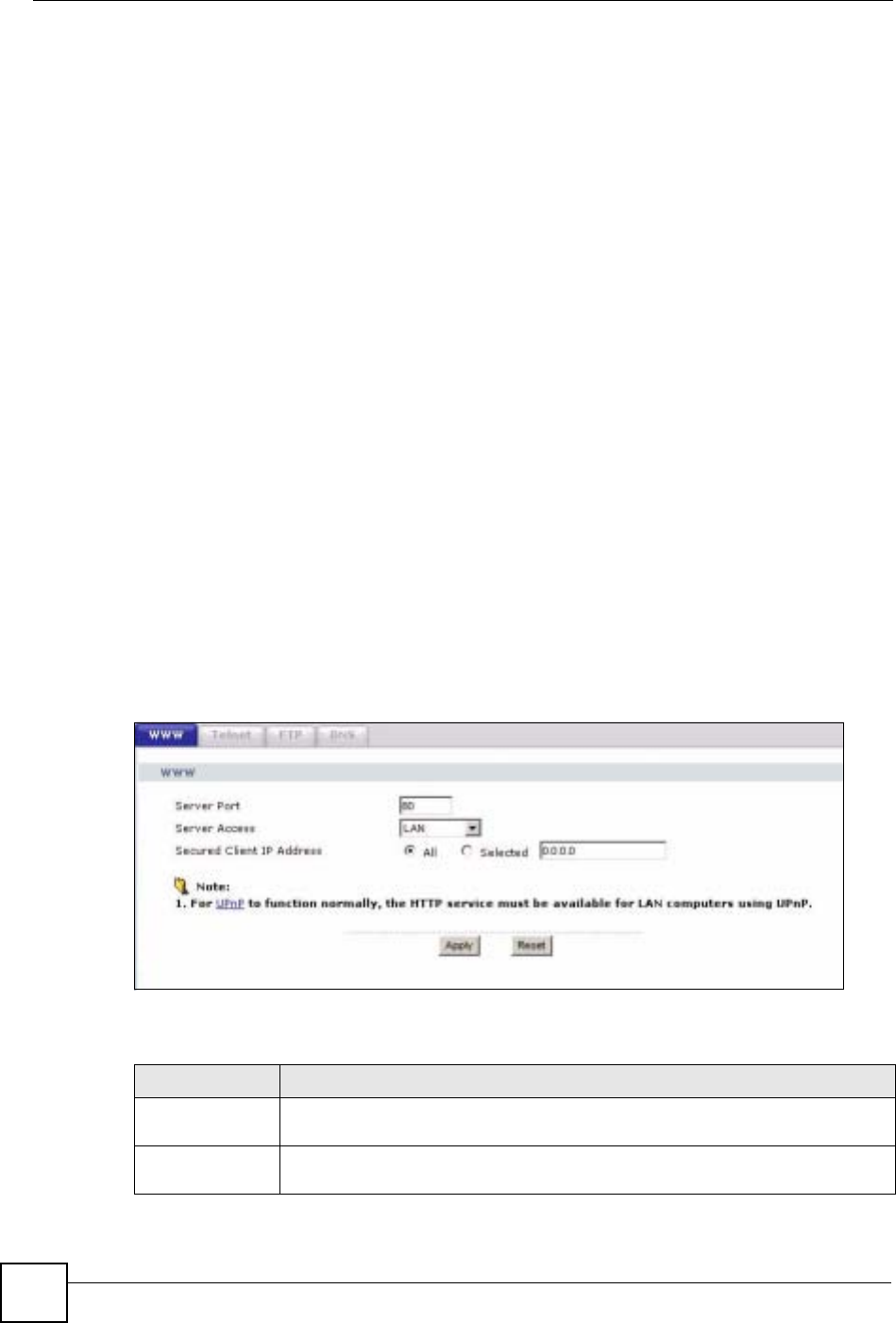
Chapter 18 Remote Management
NBG-460N User’s Guide
210
1You have disabled that service in one of the remote management screens.
2The IP address in the Secured Client IP Address field does not match the client IP
address. If it does not match, the NBG-460N will disconnect the session immediately.
3There is already another remote management session with an equal or higher priority
running. You may only have one remote management session running at one time.
4There is a firewall rule that blocks it.
18.1.2 Remote Management and NAT
When NAT is enabled:
• Use the NBG-460N’s WAN IP address when configuring from the WAN.
• Use the NBG-460N’s LAN IP address when configuring from the LAN.
18.1.3 System Timeout
There is a default system management idle timeout of five minutes (three hundred seconds).
The NBG-460N automatically logs you out if the management session remains idle for longer
than this timeout period. The management session does not time out when a statistics screen is
polling. You can change the timeout period in the System screen
18.2 WWW Screen
To change your NBG-460N’s World Wide Web settings, click Management > Remote
MGMT to display the WWW screen.
Figure 126 Management > Remote MGMT > WWW
The following table describes the labels in this screen
Table 79 Management > Remote MGMT > WWW
LABEL DESCRIPTION
Server Port You may change the server port number for a service if needed, however you must
use the same port number in order to use that service for remote management.
Server Access Select the interface(s) through which a computer may access the NBG-460N using
this service.
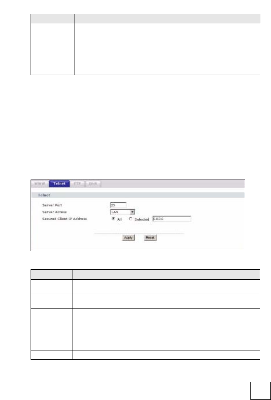
Chapter 18 Remote Management
NBG-460N User’s Guide 211
18.3 Telnet
You can use Telnet to access the NBG-460N’s command line interface. Specify which
interfaces allow Telnet access and from which IP address the access can come.
18.4 Telnet Screen
To change your NBG-460N’s Telnet settings, click Management > Remote MGMT >
Telnet. The following screen displays.
Figure 127 Management > Remote MGMT > Telnet
The following table describes the labels in this screen.
Secured Client IP
Address A secured client is a “trusted” computer that is allowed to communicate with the
NBG-460N using this service.
Select All to allow any computer to access the NBG-460N using this service.
Choose Selected to just allow the computer with the IP address that you specify to
access the NBG-460N using this service.
Apply Click Apply to save your customized settings and exit this screen.
Reset Click Reset to begin configuring this screen afresh.
LABEL DESCRIPTION
Table 80 Management > Remote MGMT > Telnet
LABEL DESCRIPTION
Server Port You may change the server port number for a service if needed, however you must
use the same port number in order to use that service for remote management.
Server Access Select the interface(s) through which a computer may access the NBG-460N using
this service.
Secured Client
IP Address A secured client is a “trusted” computer that is allowed to communicate with the
NBG-460N using this service.
Select All to allow any computer to access the NBG-460N using this service.
Choose Selected to just allow the computer with the IP address that you specify to
access the NBG-460N using this service.
Apply Click Apply to save your customized settings and exit this screen.
Reset Click Reset to begin configuring this screen afresh.
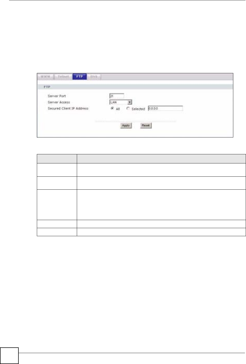
Chapter 18 Remote Management
NBG-460N User’s Guide
212
18.5 FTP Screen
You can use FTP (File Transfer Protocol) to upload and download the NBG-460N’s firmware
and configuration files. To use this feature, your computer must have an FTP client.
To change your NBG-460N’s FTP settings, click Management > Remote MGMT > FTP.
The screen appears as shown. Use this screen to specify which interfaces allow FTP access
and from which IP address the access can come.
Figure 128 Management > Remote MGMT > FTP
The following table describes the labels in this screen.
18.6 DNS Screen
Use DNS (Domain Name System) to map a domain name to its corresponding IP address and
vice versa. Refer to the chapter on Wizard Setup for background information.
To change your NBG-460N’s DNS settings, click Management > Remote MGMT > DNS.
The screen appears as shown.
Table 81 Management > Remote MGMT > FTP
LABEL DESCRIPTION
Server Port You may change the server port number for a service if needed, however you must
use the same port number in order to use that service for remote management.
Server Access Select the interface(s) through which a computer may access the NBG-460N using
this service.
Secured Client IP
Address A secured client is a “trusted” computer that is allowed to communicate with the
NBG-460N using this service.
Select All to allow any computer to access the NBG-460N using this service.
Choose Selected to just allow the computer with the IP address that you specify to
access the NBG-460N using this service.
Apply Click Apply to save your customized settings and exit this screen.
Reset Click Reset to begin configuring this screen afresh.
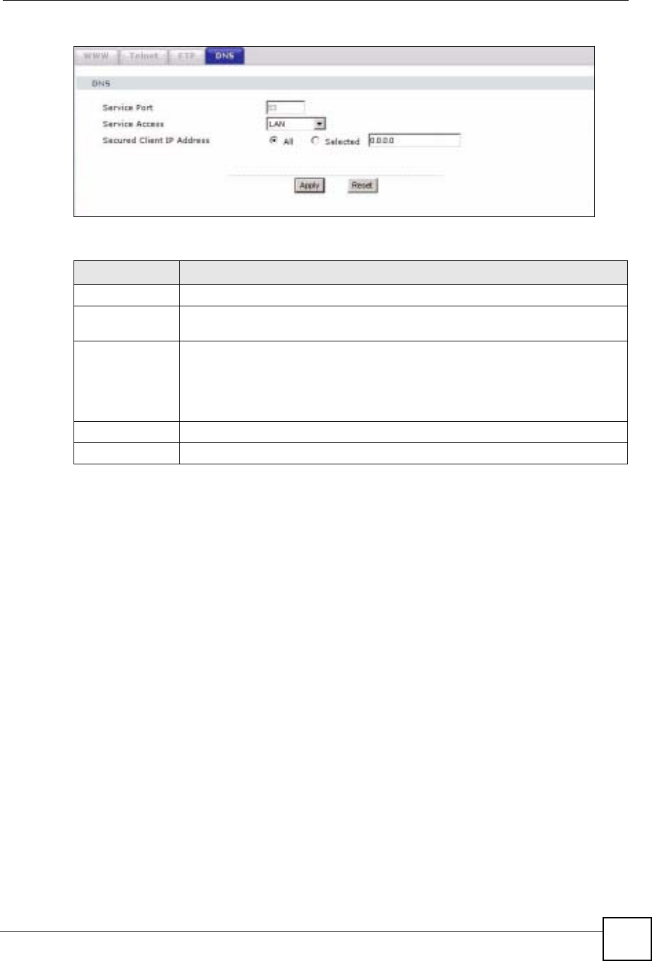
Chapter 18 Remote Management
NBG-460N User’s Guide 213
Figure 129 Management > Remote MGMT > DNS
The following table describes the labels in this screen.
Table 82 Management > Remote MGMT > DNS
LABEL DESCRIPTION
Server Port The DNS service port number is 53 and cannot be changed here.
Server Access Select the interface(s) through which a computer may send DNS queries to the
NBG-460N.
Secured Client IP
Address A secured client is a “trusted” computer that is allowed to send DNS queries to the
NBG-460N.
Select All to allow any computer to send DNS queries to the NBG-460N.
Choose Selected to just allow the computer with the IP address that you specify to
send DNS queries to the NBG-460N.
Apply Click Apply to save your customized settings and exit this screen.
Reset Click Reset to begin configuring this screen afresh.

Chapter 18 Remote Management
NBG-460N User’s Guide
214

NBG-460N User’s Guide 215
CHAPTER 19
Universal Plug-and-Play (UPnP)
This chapter introduces the UPnP feature in the web configurator.
19.1 Introducing Universal Plug and Play
Universal Plug and Play (UPnP) is a distributed, open networking standard that uses TCP/IP
for simple peer-to-peer network connectivity between devices. A UPnP device can
dynamically join a network, obtain an IP address, convey its capabilities and learn about other
devices on the network. In turn, a device can leave a network smoothly and automatically
when it is no longer in use.
See Section 19.3 on page 216 for configuration instructions.
19.1.1 How do I know if I'm using UPnP?
UPnP hardware is identified as an icon in the Network Connections folder (Windows XP).
Each UPnP compatible device installed on your network will appear as a separate icon.
Selecting the icon of a UPnP device will allow you to access the information and properties of
that device.
19.1.2 NAT Traversal
UPnP NAT traversal automates the process of allowing an application to operate through
NAT. UPnP network devices can automatically configure network addressing, announce their
presence in the network to other UPnP devices and enable exchange of simple product and
service descriptions. NAT traversal allows the following:
• Dynamic port mapping
• Learning public IP addresses
• Assigning lease times to mappings
Windows Messenger is an example of an application that supports NAT traversal and UPnP.
See the NAT chapter for more information on NAT.
19.1.3 Cautions with UPnP
The automated nature of NAT traversal applications in establishing their own services and
opening firewall ports may present network security issues. Network information and
configuration may also be obtained and modified by users in some network environments.
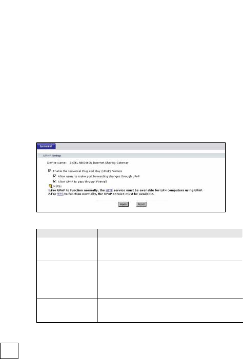
Chapter 19 Universal Plug-and-Play (UPnP)
NBG-460N User’s Guide
216
When a UPnP device joins a network, it announces its presence with a multicast message. For
security reasons, the NBG-460N allows multicast messages on the LAN only.
All UPnP-enabled devices may communicate freely with each other without additional
configuration. Disable UPnP if this is not your intention.
19.2 UPnP and ZyXEL
ZyXEL has achieved UPnP certification from the Universal Plug and Play Forum UPnP™
Implementers Corp. (UIC). ZyXEL's UPnP implementation supports Internet Gateway Device
(IGD) 1.0.
See the following sections for examples of installing and using UPnP.
19.3 UPnP Screen
Click the Management > UPnP to display the UPnP screen.
Figure 130 Management > UPnP > General
The following table describes the labels in this screen.
Table 83 Management > UPnP > General
LABEL DESCRIPTION
Enable the Universal Plug
and Play (UPnP) Feature Select this check box to activate UPnP. Be aware that anyone could
use a UPnP application to open the web configurator's login screen
without entering the NBG-460N's IP address (although you must still
enter the password to access the web configurator).
Allow users to make
configuration changes
through UPnP
Select this check box to allow UPnP-enabled applications to
automatically configure the NBG-460N so that they can communicate
through the NBG-460N, for example by using NAT traversal, UPnP
applications automatically reserve a NAT forwarding port in order to
communicate with another UPnP enabled device; this eliminates the
need to manually configure port forwarding for the UPnP enabled
application.
Allow UPnP to pass through
Firewall Select this check box to allow traffic from UPnP-enabled applications to
bypass the firewall.
Clear this check box to have the firewall block all UPnP application
packets (for example, MSN packets).
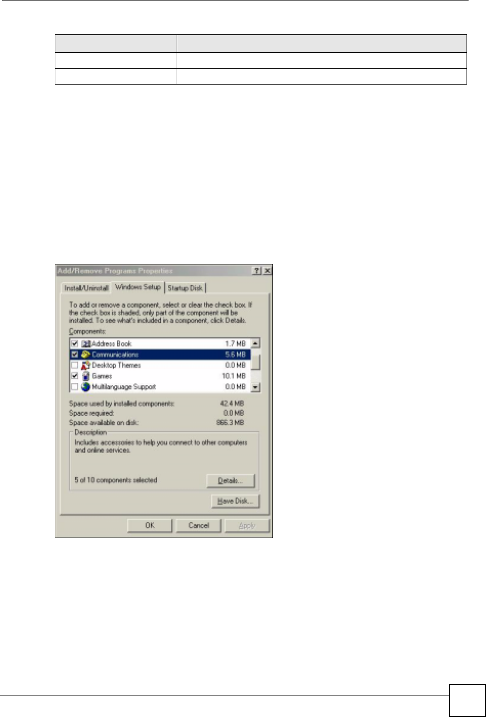
Chapter 19 Universal Plug-and-Play (UPnP)
NBG-460N User’s Guide 217
19.4 Installing UPnP in Windows Example
This section shows how to install UPnP in Windows Me and Windows XP.
19.4.0.1 Installing UPnP in Windows Me
Follow the steps below to install the UPnP in Windows Me.
1Click Start and Control Panel. Double-click Add/Remove Programs.
2Click on the Windows Setup tab and select Communication in the Components
selection box. Click Details.
Figure 131 Add/Remove Programs: Windows Setup: Communication
3In the Communications window, select the Universal Plug and Play check box in the
Components selection box.
Apply Click Apply to save the setting to the NBG-460N.
Reset Click Reset to begin configuring this screen afresh.
Table 83 Management > UPnP > General
LABEL DESCRIPTION
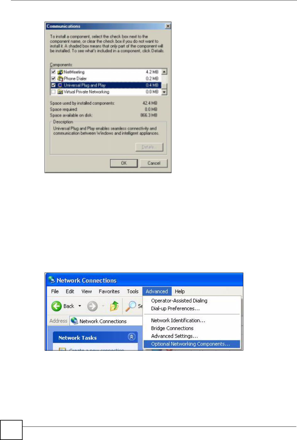
Chapter 19 Universal Plug-and-Play (UPnP)
NBG-460N User’s Guide
218
Figure 132 Add/Remove Programs: Windows Setup: Communication: Components
4Click OK to go back to the Add/Remove Programs Properties window and click
Next.
5Restart the computer when prompted.
Installing UPnP in Windows XP
Follow the steps below to install the UPnP in Windows XP.
1Click Start and Control Panel.
2Double-click Network Connections.
3In the Network Connections window, click Advanced in the main menu and select
Optional Networking Components ….
Figure 133 Network Connections
4The Windows Optional Networking Components Wizard window displays. Select
Networking Service in the Components selection box and click Details.
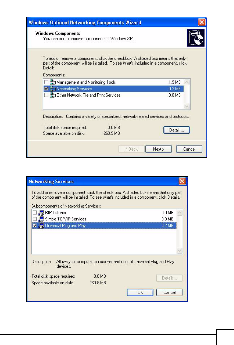
Chapter 19 Universal Plug-and-Play (UPnP)
NBG-460N User’s Guide 219
Figure 134 Windows Optional Networking Components Wizard
5In the Networking Services window, select the Universal Plug and Play check box.
Figure 135 Networking Services
6Click OK to go back to the Windows Optional Networking Component Wizard
window and click Next.
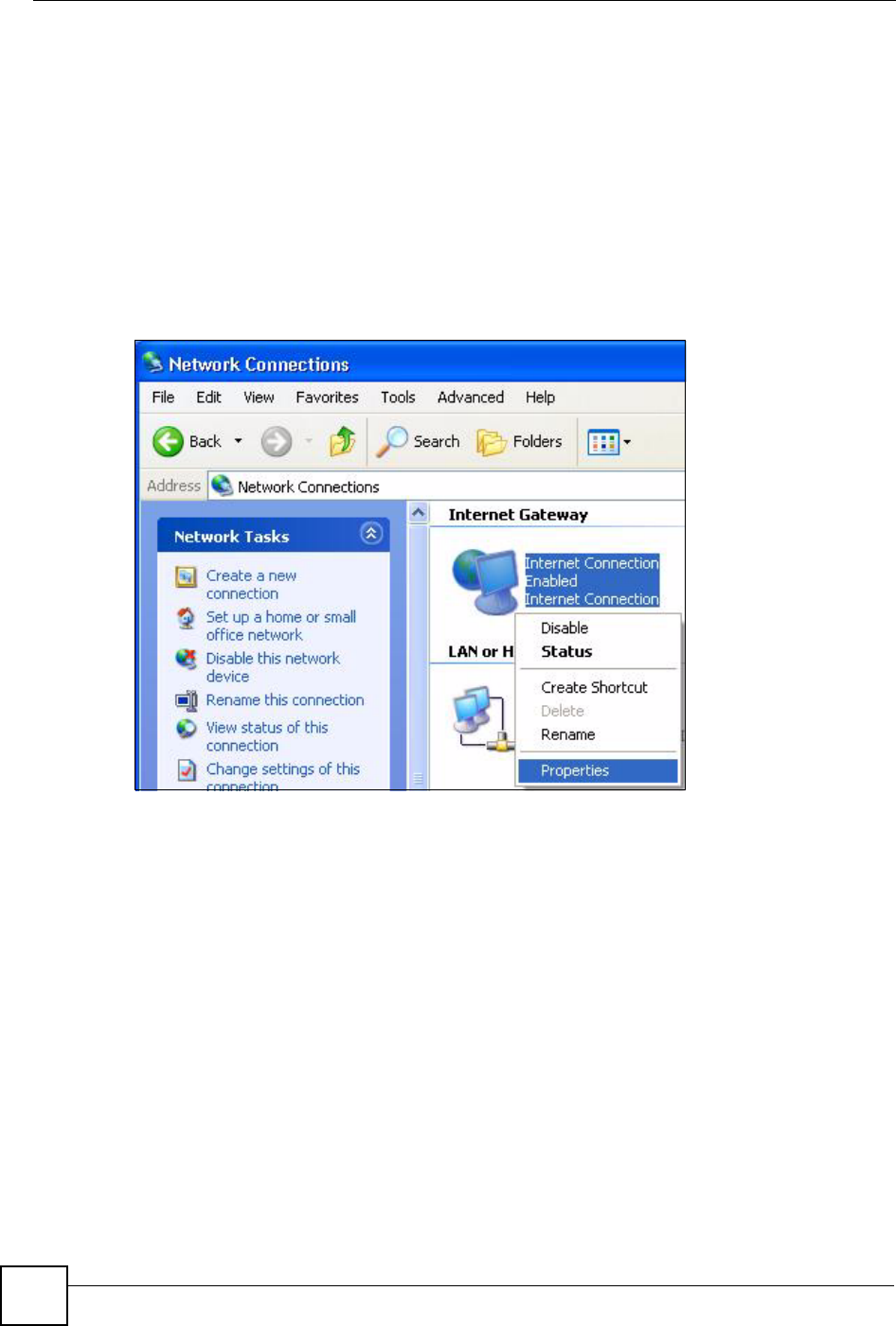
Chapter 19 Universal Plug-and-Play (UPnP)
NBG-460N User’s Guide
220
19.4.0.2 Using UPnP in Windows XP Example
This section shows you how to use the UPnP feature in Windows XP. You must already have
UPnP installed in Windows XP and UPnP activated on the NBG-460N.
Make sure the computer is connected to a LAN port of the NBG-460N. Turn on your computer
and the NBG-460N.
Auto-discover Your UPnP-enabled Network Device
1Click Start and Control Panel. Double-click Network Connections. An icon displays
under Internet Gateway.
2Right-click the icon and select Properties.
Figure 136 Network Connections
3In the Internet Connection Properties window, click Settings to see the port mappings
there were automatically created.
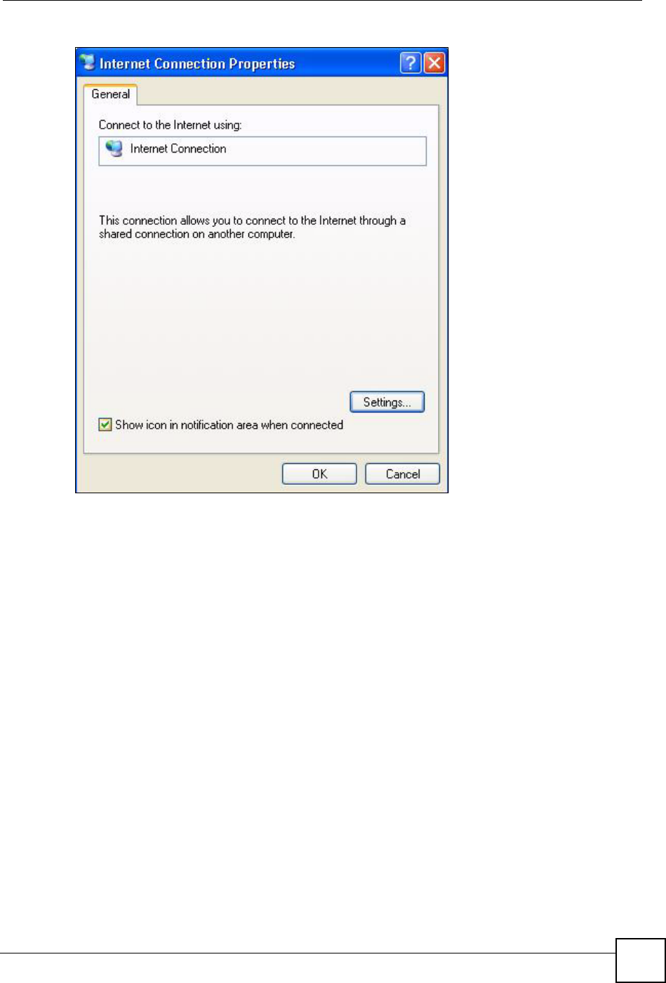
Chapter 19 Universal Plug-and-Play (UPnP)
NBG-460N User’s Guide 221
Figure 137 Internet Connection Properties
4You may edit or delete the port mappings or click Add to manually add port mappings.
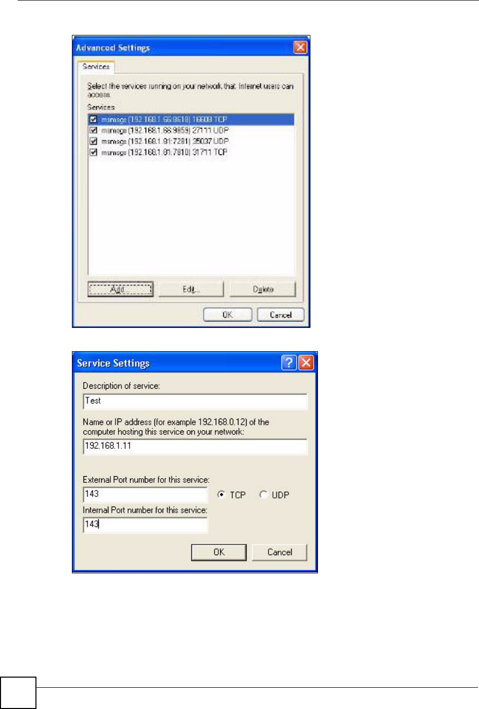
Chapter 19 Universal Plug-and-Play (UPnP)
NBG-460N User’s Guide
222
Figure 138 Internet Connection Properties: Advanced Settings
Figure 139 Internet Connection Properties: Advanced Settings: Add
5When the UPnP-enabled device is disconnected from your computer, all port mappings
will be deleted automatically.
6Select Show icon in notification area when connected option and click OK. An icon
displays in the system tray.
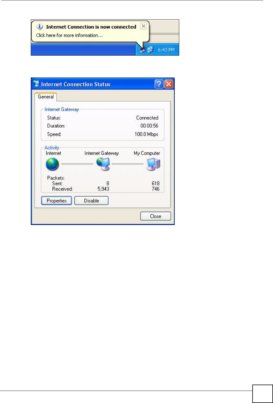
Chapter 19 Universal Plug-and-Play (UPnP)
NBG-460N User’s Guide 223
Figure 140 System Tray Icon
7Double-click on the icon to display your current Internet connection status.
Figure 141 Internet Connection Status
Web Configurator Easy Access
With UPnP, you can access the web-based configurator on the NBG-460N without finding out
the IP address of the NBG-460N first. This comes helpful if you do not know the IP address of
the NBG-460N.
Follow the steps below to access the web configurator.
1Click Start and then Control Panel.
2Double-click Network Connections.
3Select My Network Places under Other Places.
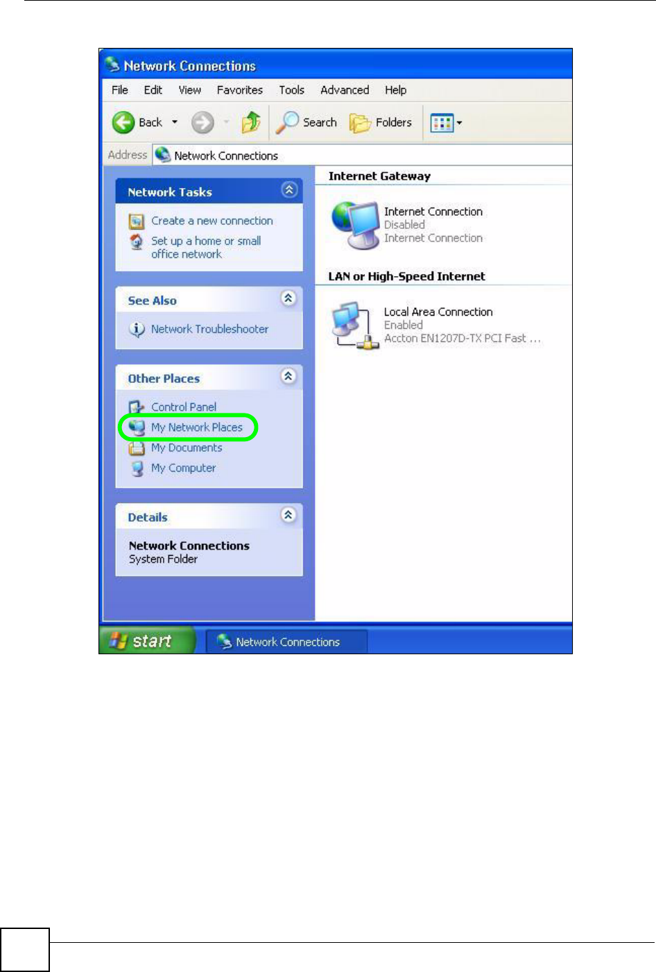
Chapter 19 Universal Plug-and-Play (UPnP)
NBG-460N User’s Guide
224
Figure 142 Network Connections
4An icon with the description for each UPnP-enabled device displays under Local
Network.
5Right-click on the icon for your NBG-460N and select Invoke. The web configurator
login screen displays.
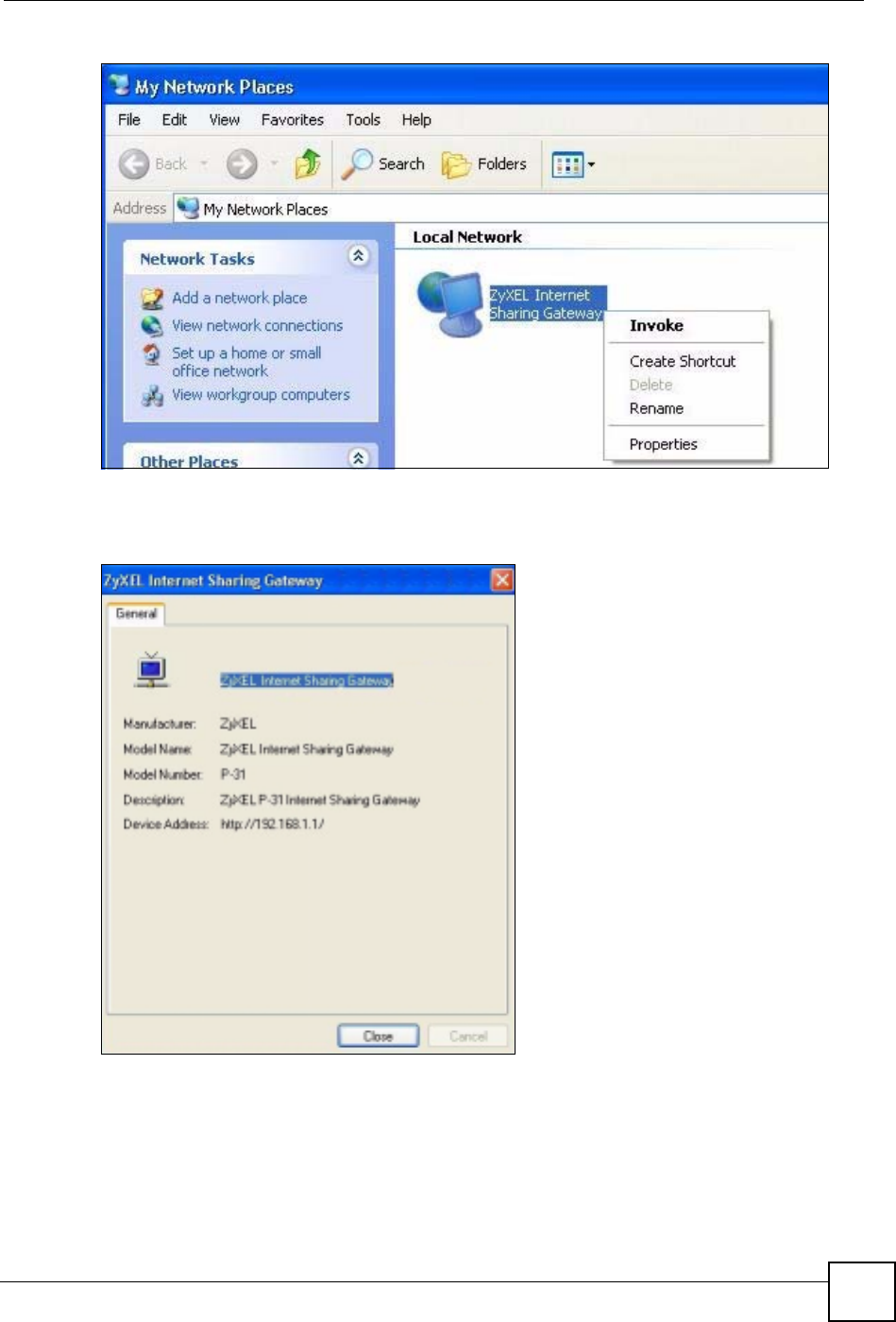
Chapter 19 Universal Plug-and-Play (UPnP)
NBG-460N User’s Guide 225
Figure 143 Network Connections: My Network Places
6Right-click on the icon for your NBG-460N and select Properties. A properties window
displays with basic information about the NBG-460N.
Figure 144 Network Connections: My Network Places: Properties: Example

Chapter 19 Universal Plug-and-Play (UPnP)
NBG-460N User’s Guide
226

227
PART V
Maintenance and
Troubleshooting
System (229)
Logs (233)
Tools (251)
Configuration Mode (257)
Sys Op Mode (259)
Language (263)
Troubleshooting (265)

228
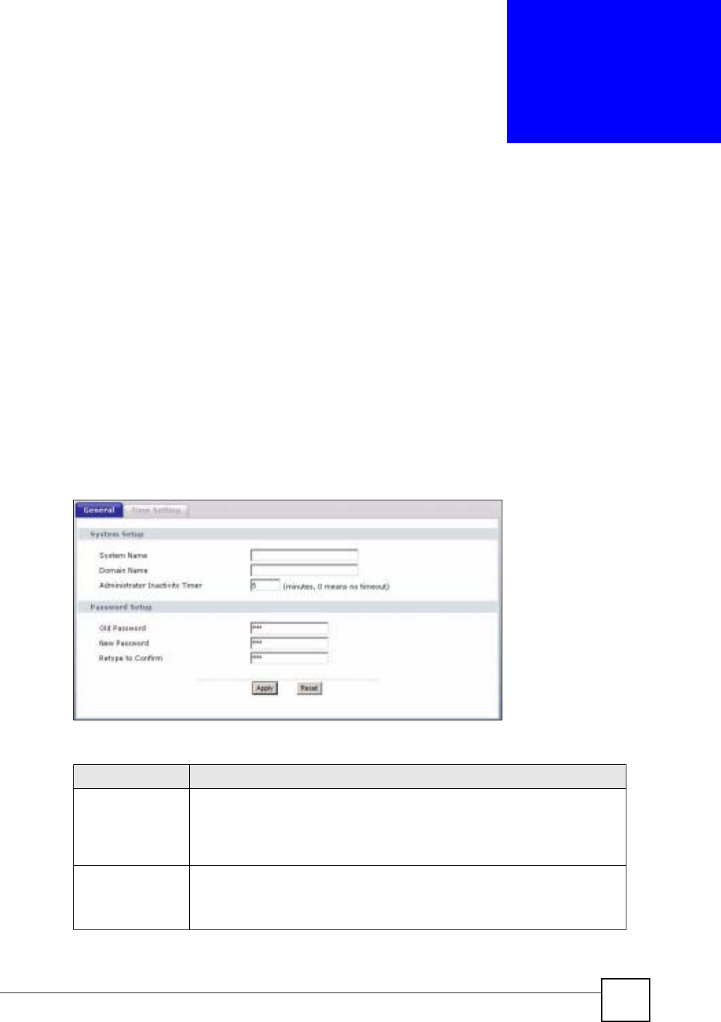
NBG-460N User’s Guide 229
CHAPTER 20
System
This chapter provides information on the System screens.
20.1 System Overview
See the chapter about wizard setup for more information on the next few screens.
20.2 System General Screen
Click Maintenance > System. The following screen displays.
Figure 145 Maintenance > System > General
The following table describes the labels in this screen.
Table 84 Maintenance > System > General
LABEL DESCRIPTION
System Name System Name is a unique name to identify the NBG-460N in an Ethernet
network. It is recommended you enter your computer’s “Computer name” in this
field (see the chapter about wizard setup for how to find your computer’s name).
This name can be up to 30 alphanumeric characters long. Spaces are not
allowed, but dashes “-” and underscores "_" are accepted.
Domain Name Enter the domain name (if you know it) here. If you leave this field blank, the ISP
may assign a domain name via DHCP.
The domain name entered by you is given priority over the ISP assigned domain
name.
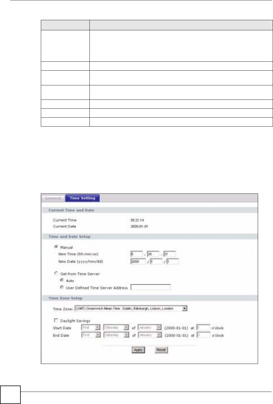
Chapter 20 System
NBG-460N User’s Guide
230
20.3 Time Setting Screen
To change your NBG-460N’s time and date, click Maintenance > System > Time Setting.
The screen appears as shown. Use this screen to configure the NBG-460N’s time based on
your local time zone.
Figure 146 Maintenance > System > Time Setting
Administrator
Inactivity Timer Type how many minutes a management session can be left idle before the
session times out. The default is 5 minutes. After it times out you have to log in
with your password again. Very long idle timeouts may have security risks. A
value of "0" means a management session never times out, no matter how long it
has been left idle (not recommended).
Password Setup Change your NBG-460N’s password (recommended) using the fields as shown.
Old Password Type the default password or the existing password you use to access the
system in this field.
New Password Type your new system password (up to 30 characters). Note that as you type a
password, the screen displays an asterisk (*) for each character you type.
Retype to Confirm Type the new password again in this field.
Apply Click Apply to save your changes back to the NBG-460N.
Reset Click Reset to begin configuring this screen afresh.
Table 84 Maintenance > System > General
LABEL DESCRIPTION

Chapter 20 System
NBG-460N User’s Guide 231
The following table describes the labels in this screen.
Table 85 Maintenance > System > Time Setting
LABEL DESCRIPTION
Current Time and
Date
Current Time This field displays the time of your NBG-460N.
Each time you reload this page, the NBG-460N synchronizes the time with the
time server.
Current Date This field displays the date of your NBG-460N.
Each time you reload this page, the NBG-460N synchronizes the date with the
time server.
Time and Date
Setup
Manual Select this radio button to enter the time and date manually. If you configure a
new time and date, Time Zone and Daylight Saving at the same time, the new
time and date you entered has priority and the Time Zone and Daylight Saving
settings do not affect it.
New Time
(hh:mm:ss)
This field displays the last updated time from the time server or the last time
configured manually.
When you set Time and Date Setup to Manual, enter the new time in this field
and then click Apply.
New Date
(yyyy/mm/dd)
This field displays the last updated date from the time server or the last date
configured manually.
When you set Time and Date Setup to Manual, enter the new date in this field
and then click Apply.
Get from Time
Server Select this radio button to have the NBG-460N get the time and date from the
time server you specified below.
Auto Select Auto to have the NBG-460N automatically search for an available time
server and synchronize the date and time with the time server after you click
Apply.
User Defined Time
Server Address Select User Defined Time Server Address and enter the IP address or URL
(up to 20 extended ASCII characters in length) of your time server. Check with
your ISP/network administrator if you are unsure of this information.
Time Zone Setup
Time Zone Choose the time zone of your location. This will set the time difference between
your time zone and Greenwich Mean Time (GMT).
Daylight Savings Daylight saving is a period from late spring to early fall when many countries set
their clocks ahead of normal local time by one hour to give more daytime light in
the evening.
Select this option if you use Daylight Saving Time.
Start Date Configure the day and time when Daylight Saving Time starts if you selected
Daylight Savings. The o'clock field uses the 24 hour format. Here are a
couple of examples:
Daylight Saving Time starts in most parts of the United States on the first
Sunday of April. Each time zone in the United States starts using Daylight
Saving Time at 2 A.M. local time. So in the United States you would select
First,Sunday,April and type 2 in the o'clock field.
Daylight Saving Time starts in the European Union on the last Sunday of March.
All of the time zones in the European Union start using Daylight Saving Time at
the same moment (1 A.M. GMT or UTC). So in the European Union you would
select Last,Sunday,March. The time you type in the o'clock field depends on
your time zone. In Germany for instance, you would type 2 because Germany's
time zone is one hour ahead of GMT or UTC (GMT+1).

Chapter 20 System
NBG-460N User’s Guide
232
End Date Configure the day and time when Daylight Saving Time ends if you selected
Daylight Savings. The o'clock field uses the 24 hour format. Here are a
couple of examples:
Daylight Saving Time ends in the United States on the last Sunday of October.
Each time zone in the United States stops using Daylight Saving Time at 2 A.M.
local time. So in the United States you would select Last,Sunday,October
and type 2 in the o'clock field.
Daylight Saving Time ends in the European Union on the last Sunday of
October. All of the time zones in the European Union stop using Daylight Saving
Time at the same moment (1 A.M. GMT or UTC). So in the European Union you
would select Last,Sunday,October. The time you type in the o'clock field
depends on your time zone. In Germany for instance, you would type 2 because
Germany's time zone is one hour ahead of GMT or UTC (GMT+1).
Apply Click Apply to save your changes back to the NBG-460N.
Reset Click Reset to begin configuring this screen afresh.
Table 85 Maintenance > System > Time Setting
LABEL DESCRIPTION
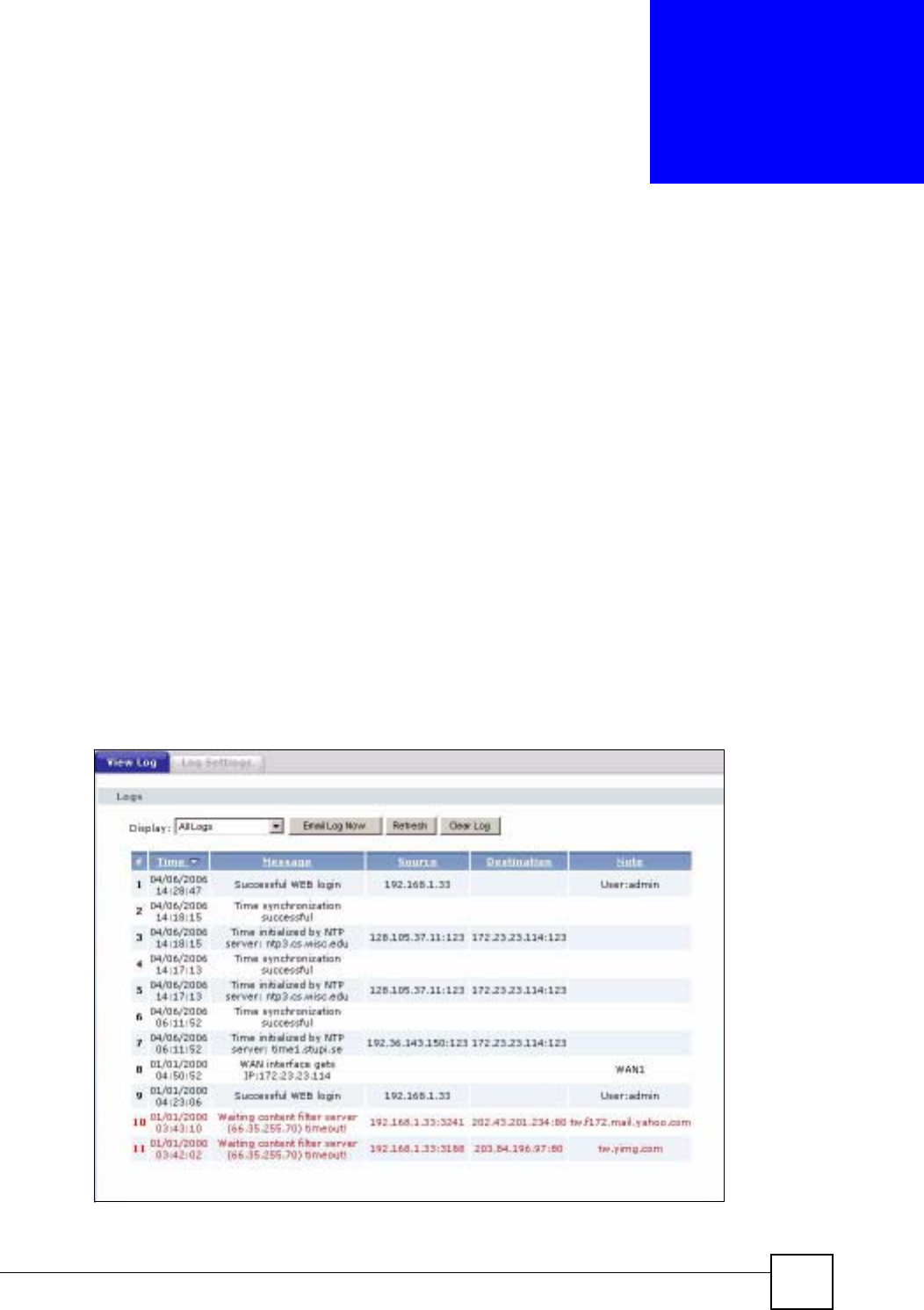
NBG-460N User’s Guide 233
CHAPTER 21
Logs
This chapter contains information about configuring general log settings and viewing the
NBG-460N’s logs. Refer to the appendices for example log message explanations.
21.1 View Log
The web configurator allows you to look at all of the NBG-460N’s logs in one location.
Click Maintenance > Logs to open the View Log screen.
Use the View Log screen to see the logs for the categories that you selected in the Log
Settings screen (see Section 21.2 on page 234). Options include logs about system
maintenance, system errors, access control, allowed or blocked web sites, blocked web
features (such as ActiveX controls, Java and cookies), attacks (such as DoS) and IPSec.
Log entries in red indicate system error logs. The log wraps around and deletes the old entries
after it fills. Click a column heading to sort the entries. A triangle indicates ascending or
descending sort order.
Figure 147 Maintenance > Logs > View Log
Chapter 21 Logs
NBG-460N User’s Guide
234
The following table describes the labels in this screen.
21.2 Log Settings
You can configure the NBG-460N’s general log settings in one location.
Click Maintenance > Logs > Log Settings to open the Log Settings screen.
Use the Log Settings screen to configure to where the NBG-460N is to send logs; the schedule
for when the NBG-460N is to send the logs and which logs and/or immediate alerts the NBG-
460N to send.
An alert is a type of log that warrants more serious attention. They include system errors,
attacks (access control) and attempted access to blocked web sites or web sites with restricted
web features such as cookies, active X and so on. Some categories such as System Errors
consist of both logs and alerts. You may differentiate them by their color in the View Log
screen. Alerts display in red and logs display in black.
Alerts are e-mailed as soon as they happen. Logs may be e-mailed as soon as the log is full
(see Log Schedule). Selecting many alert and/or log categories (especially Access Control)
may result in many e-mails being sent.
Table 86 Maintenance > Logs > View Log
LABEL DESCRIPTION
Display The categories that you select in the Log Settings page (see Section 21.2 on
page 234) display in the drop-down list box.
Select a category of logs to view; select All Logs to view logs from all of the log
categories that you selected in the Log Settings page.
Email Log Now Click Email Log Now to send the log screen to the e-mail address specified in
the Log Settings page (make sure that you have first filled in the Address Info
fields in Log Settings).
Refresh Click Refresh to renew the log screen.
Clear Log Click Clear Log to delete all the logs.
Time This field displays the time the log was recorded. See the chapter on system
maintenance and information to configure the NBG-460N’s time and date.
Message This field states the reason for the log.
Source This field lists the source IP address and the port number of the incoming
packet.
Destination This field lists the destination IP address and the port number of the incoming
packet.
Note This field displays additional information about the log entry.
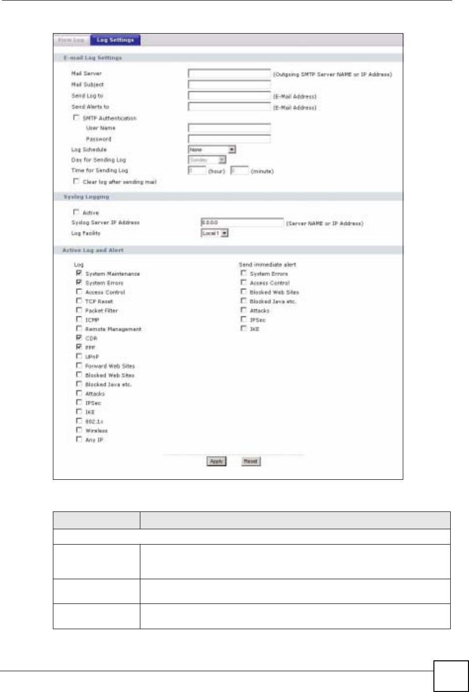
Chapter 21 Logs
NBG-460N User’s Guide 235
Figure 148 Maintenance > Logs > Log Settings
The following table describes the labels in this screen.
Table 87 Maintenance > Logs > Log Settings
LABEL DESCRIPTION
E-mail Log Settings
Mail Server Enter the server name or the IP address of the mail server for the e-mail
addresses specified below. If this field is left blank, logs and alert messages will
not be sent via E-mail.
Mail Subject Type a title that you want to be in the subject line of the log e-mail message that
the NBG-460N sends. Not all NBG-460N models have this field.
Send Log To The NBG-460N sends logs to the e-mail address specified in this field. If this
field is left blank, the NBG-460N does not send logs via e-mail.

Chapter 21 Logs
NBG-460N User’s Guide
236
Send Alerts To Alerts are real-time notifications that are sent as soon as an event, such as a
DoS attack, system error, or forbidden web access attempt occurs. Enter the E-
mail address where the alert messages will be sent. Alerts include system
errors, attacks and attempted access to blocked web sites. If this field is left
blank, alert messages will not be sent via E-mail.
SMTP
Authentication SMTP (Simple Mail Transfer Protocol) is the message-exchange standard for
the Internet. SMTP enables you to move messages from one e-mail server to
another.
Select the check box to activate SMTP authentication. If mail server
authentication is needed but this feature is disabled, you will not receive the e-
mail logs.
User Name Enter the user name (up to 31 characters) (usually the user name of a mail
account).
Password Enter the password associated with the user name above.
Log Schedule This drop-down menu is used to configure the frequency of log messages being
sent as E-mail:
•Daily
•Weekly
• Hourly
• When Log is Full
• None.
If you select Weekly or Daily, specify a time of day when the E-mail should be
sent. If you select Weekly, then also specify which day of the week the E-mail
should be sent. If you select When Log is Full, an alert is sent when the log fills
up. If you select None, no log messages are sent.
Day for Sending Log Use the drop down list box to select which day of the week to send the logs.
Time for Sending
Log Enter the time of the day in 24-hour format (for example 23:00 equals 11:00 pm)
to send the logs.
Clear log after
sending mail Select the checkbox to delete all the logs after the NBG-460N sends an E-mail
of the logs.
Syslog Logging The NBG-460N sends a log to an external syslog server.
Active Click Active to enable syslog logging.
Syslog Server IP
Address Enter the server name or IP address of the syslog server that will log the
selected categories of logs.
Log Facility Select a location from the drop down list box. The log facility allows you to log
the messages to different files in the syslog server. Refer to the syslog server
manual for more information.
Active Log and Alert
Log Select the categories of logs that you want to record.
Send Immediate
Alert Select log categories for which you want the NBG-460N to send E-mail alerts
immediately.
Apply Click Apply to save your changes.
Reset Click Reset to begin configuring this screen afresh.
Table 87 Maintenance > Logs > Log Settings
LABEL DESCRIPTION

Chapter 21 Logs
NBG-460N User’s Guide 237
21.3 Log Descriptions
This section provides descriptions of example log messages.
Table 88 System Maintenance Logs
LOG MESSAGE DESCRIPTION
Time calibration is
successful
The router has adjusted its time based on information from
the time server.
Time calibration failed The router failed to get information from the time server.
WAN interface gets IP:%s A WAN interface got a new IP address from the DHCP,
PPPoE, PPTP or dial-up server.
DHCP client IP expired A DHCP client's IP address has expired.
DHCP server assigns%s The DHCP server assigned an IP address to a client.
Successful WEB login Someone has logged on to the router's web configurator
interface.
WEB login failed Someone has failed to log on to the router's web configurator
interface.
Successful TELNET login Someone has logged on to the router via telnet.
TELNET login failed Someone has failed to log on to the router via telnet.
Successful FTP login Someone has logged on to the router via ftp.
FTP login failed Someone has failed to log on to the router via ftp.
NAT Session Table is Full! The maximum number of NAT session table entries has been
exceeded and the table is full.
Starting Connectivity
Monitor
Starting Connectivity Monitor.
Time initialized by Daytime
Server
The router got the time and date from the Daytime server.
Time initialized by Time
server
The router got the time and date from the time server.
Time initialized by NTP
server
The router got the time and date from the NTP server.
Connect to Daytime server
fail
The router was not able to connect to the Daytime server.
Connect to Time server fail The router was not able to connect to the Time server.
Connect to NTP server fail The router was not able to connect to the NTP server.
Too large ICMP packet has
been dropped
The router dropped an ICMP packet that was too large.
Configuration Change: PC =
0x%x, Task ID = 0x%x
The router is saving configuration changes.
Successful SSH login Someone has logged on to the router’s SSH server.
SSH login failed Someone has failed to log on to the router’s SSH server.
Successful HTTPS login Someone has logged on to the router's web configurator
interface using HTTPS protocol.
HTTPS login failed Someone has failed to log on to the router's web configurator
interface using HTTPS protocol.
Chapter 21 Logs
NBG-460N User’s Guide
238
Table 89 System Error Logs
LOG MESSAGE DESCRIPTION
%s exceeds the max.
number of session per
host!
This attempt to create a NAT session exceeds the maximum
number of NAT session table entries allowed to be created per
host.
setNetBIOSFilter: calloc
error
The router failed to allocate memory for the NetBIOS filter
settings.
readNetBIOSFilter: calloc
error
The router failed to allocate memory for the NetBIOS filter
settings.
WAN connection is down. A WAN connection is down. You cannot access the network
through this interface.
Table 90 Access Control Logs
LOG MESSAGE DESCRIPTION
Firewall default policy: [TCP |
UDP | IGMP | ESP | GRE | OSPF]
<Packet Direction>
Attempted TCP/UDP/IGMP/ESP/GRE/OSPF access
matched the default policy and was blocked or forwarded
according to the default policy’s setting.
Firewall rule [NOT] match:[TCP |
UDP | IGMP | ESP | GRE | OSPF]
<Packet Direction>, <rule:%d>
Attempted TCP/UDP/IGMP/ESP/GRE/OSPF access
matched (or did not match) a configured firewall rule
(denoted by its number) and was blocked or forwarded
according to the rule.
Triangle route packet forwarded:
[TCP | UDP | IGMP | ESP | GRE |
OSPF]
The firewall allowed a triangle route session to pass
through.
Packet without a NAT table entry
blocked: [TCP | UDP | IGMP | ESP
| GRE | OSPF]
The router blocked a packet that didn't have a
corresponding NAT table entry.
Router sent blocked web site
message: TCP
The router sent a message to notify a user that the router
blocked access to a web site that the user requested.
Table 91 TCP Reset Logs
LOG MESSAGE DESCRIPTION
Under SYN flood attack,
sent TCP RST
The router sent a TCP reset packet when a host was under a SYN
flood attack (the TCP incomplete count is per destination host.)
Exceed TCP MAX
incomplete, sent TCP RST
The router sent a TCP reset packet when the number of TCP
incomplete connections exceeded the user configured threshold.
(the TCP incomplete count is per destination host.) Note: Refer to
TCP Maximum Incomplete in the Firewall Attack Alerts screen.
Peer TCP state out of
order, sent TCP RST
The router sent a TCP reset packet when a TCP connection state
was out of order.Note: The firewall refers to RFC793 Figure 6 to
check the TCP state.
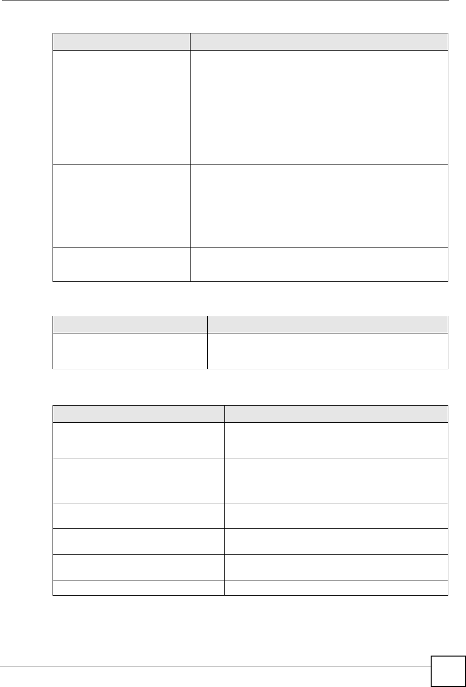
Chapter 21 Logs
NBG-460N User’s Guide 239
Firewall session time
out, sent TCP RST
The router sent a TCP reset packet when a dynamic firewall
session timed out.
The default timeout values are as follows:
ICMP idle timeout: 3 minutes
UDP idle timeout: 3 minutes
TCP connection (three way handshaking) timeout: 270 seconds
TCP FIN-wait timeout: 2 MSL (Maximum Segment Lifetime set in
the TCP header).
TCP idle (established) timeout (s): 150 minutes
TCP reset timeout: 10 seconds
Exceed MAX incomplete,
sent TCP RST
The router sent a TCP reset packet when the number of
incomplete connections (TCP and UDP) exceeded the user-
configured threshold. (Incomplete count is for all TCP and UDP
connections through the firewall.)Note: When the number of
incomplete connections (TCP + UDP) > “Maximum Incomplete
High”, the router sends TCP RST packets for TCP connections
and destroys TOS (firewall dynamic sessions) until incomplete
connections < “Maximum Incomplete Low”.
Access block, sent TCP
RST
The router sends a TCP RST packet and generates this log if you
turn on the firewall TCP reset mechanism (via CI command: "sys
firewall tcprst").
Table 92 Packet Filter Logs
LOG MESSAGE DESCRIPTION
[TCP | UDP | ICMP | IGMP |
Generic] packet filter
matched (set:%d, rule:%d)
Attempted access matched a configured filter rule (denoted
by its set and rule number) and was blocked or forwarded
according to the rule.
Table 93 ICMP Logs
LOG MESSAGE DESCRIPTION
Firewall default policy: ICMP
<Packet Direction>, <type:%d>,
<code:%d>
ICMP access matched the default policy and was
blocked or forwarded according to the user's setting. For
type and code details, see Table 104 on page 247.
Firewall rule [NOT] match: ICMP
<Packet Direction>, <rule:%d>,
<type:%d>, <code:%d>
ICMP access matched (or didn’t match) a firewall rule
(denoted by its number) and was blocked or forwarded
according to the rule. For type and code details, see
Table 104 on page 247.
Triangle route packet forwarded:
ICMP
The firewall allowed a triangle route session to pass
through.
Packet without a NAT table entry
blocked: ICMP
The router blocked a packet that didn’t have a
corresponding NAT table entry.
Unsupported/out-of-order ICMP:
ICMP
The firewall does not support this kind of ICMP packets
or the ICMP packets are out of order.
Router reply ICMP packet: ICMP The router sent an ICMP reply packet to the sender.
Table 91 TCP Reset Logs (continued)
LOG MESSAGE DESCRIPTION
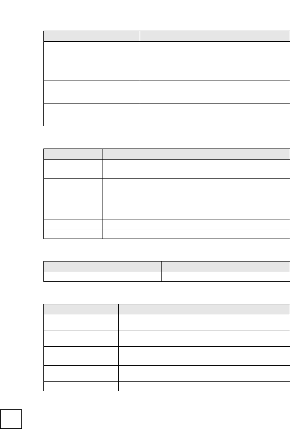
Chapter 21 Logs
NBG-460N User’s Guide
240
Table 94 CDR Logs
LOG MESSAGE DESCRIPTION
board%d line%d channel%d,
call%d,%s C01 Outgoing Call
dev=%x ch=%x%s
The router received the setup requirements for a call. “call” is
the reference (count) number of the call. “dev” is the device
type (3 is for dial-up, 6 is for PPPoE, 10 is for PPTP).
"channel" or “ch” is the call channel ID.For example,"board 0
line 0 channel 0, call 3, C01 Outgoing Call dev=6 ch=0
"Means the router has dialed to the PPPoE server 3 times.
board%d line%d channel%d,
call%d,%s C02 OutCall
Connected%d%s
The PPPoE, PPTP or dial-up call is connected.
board%d line%d channel%d,
call%d,%s C02 Call
Terminated
The PPPoE, PPTP or dial-up call was disconnected.
Table 95 PPP Logs
LOG MESSAGE DESCRIPTION
ppp:LCP Starting The PPP connection’s Link Control Protocol stage has started.
ppp:LCP Opening The PPP connection’s Link Control Protocol stage is opening.
ppp:CHAP Opening The PPP connection’s Challenge Handshake Authentication Protocol stage is
opening.
ppp:IPCP
Starting
The PPP connection’s Internet Protocol Control Protocol stage is starting.
ppp:IPCP Opening The PPP connection’s Internet Protocol Control Protocol stage is opening.
ppp:LCP Closing The PPP connection’s Link Control Protocol stage is closing.
ppp:IPCP Closing The PPP connection’s Internet Protocol Control Protocol stage is closing.
Table 96 UPnP Logs
LOG MESSAGE DESCRIPTION
UPnP pass through Firewall UPnP packets can pass through the firewall.
Table 97 Content Filtering Logs
LOG MESSAGE DESCRIPTION
%s: Keyword blocking The content of a requested web page matched a user defined
keyword.
%s: Not in trusted web
list
The web site is not in a trusted domain, and the router blocks all traffic
except trusted domain sites.
%s: Forbidden Web site The web site is in the forbidden web site list.
%s: Contains ActiveX The web site contains ActiveX.
%s: Contains Java
applet
The web site contains a Java applet.
%s: Contains cookie The web site contains a cookie.
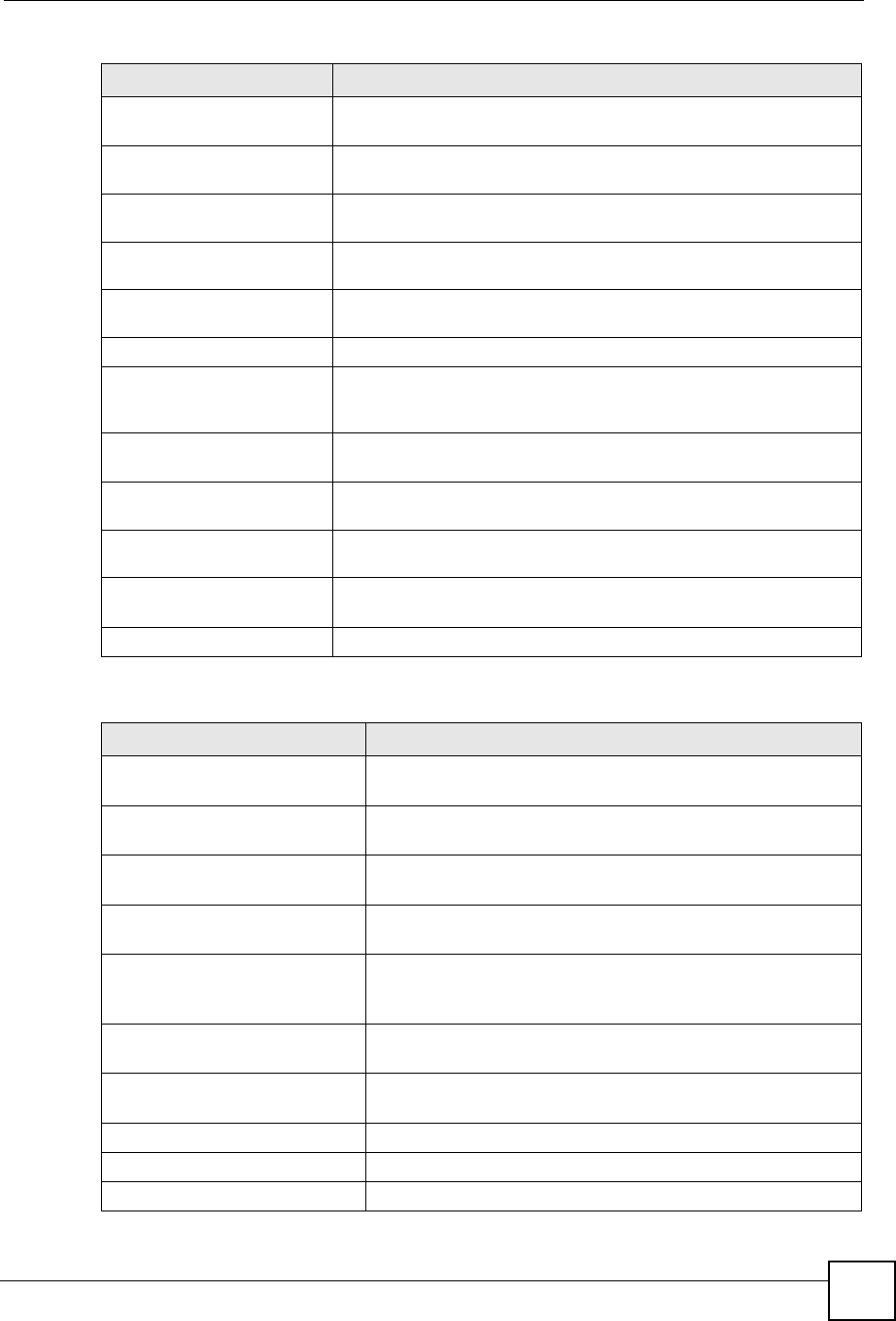
Chapter 21 Logs
NBG-460N User’s Guide 241
%s: Proxy mode
detected
The router detected proxy mode in the packet.
%s The content filter server responded that the web site is in the blocked
category list, but it did not return the category type.
%s:%s The content filter server responded that the web site is in the blocked
category list, and returned the category type.
%s(cache hit) The system detected that the web site is in the blocked list from the
local cache, but does not know the category type.
%s:%s(cache hit) The system detected that the web site is in blocked list from the local
cache, and knows the category type.
%s: Trusted Web site The web site is in a trusted domain.
%s When the content filter is not on according to the time schedule or you
didn't select the "Block Matched Web Site” check box, the system
forwards the web content.
Waiting content filter
server timeout
The external content filtering server did not respond within the timeout
period.
DNS resolving failed The NBG-460N cannot get the IP address of the external content
filtering via DNS query.
Creating socket failed The NBG-460N cannot issue a query because TCP/IP socket creation
failed, port:port number.
Connecting to content
filter server fail
The connection to the external content filtering server failed.
License key is invalid The external content filtering license key is invalid.
Table 98 Attack Logs
LOG MESSAGE DESCRIPTION
attack [TCP | UDP | IGMP
| ESP | GRE | OSPF]
The firewall detected a TCP/UDP/IGMP/ESP/GRE/OSPF attack.
attack ICMP (type:%d,
code:%d)
The firewall detected an ICMP attack. For type and code details,
see Table 104 on page 247.
land [TCP | UDP | IGMP |
ESP | GRE | OSPF]
The firewall detected a TCP/UDP/IGMP/ESP/GRE/OSPF land
attack.
land ICMP (type:%d,
code:%d)
The firewall detected an ICMP land attack. For type and code
details, see Table 104 on page 247.
ip spoofing - WAN [TCP |
UDP | IGMP | ESP | GRE |
OSPF]
The firewall detected an IP spoofing attack on the WAN port.
ip spoofing - WAN ICMP
(type:%d, code:%d)
The firewall detected an ICMP IP spoofing attack on the WAN
port. For type and code details, see Table 104 on page 247.
icmp echo: ICMP (type:%d,
code:%d)
The firewall detected an ICMP echo attack. For type and code
details, see Table 104 on page 247.
syn flood TCP The firewall detected a TCP syn flood attack.
ports scan TCP The firewall detected a TCP port scan attack.
teardrop TCP The firewall detected a TCP teardrop attack.
Table 97 Content Filtering Logs (continued)
LOG MESSAGE DESCRIPTION
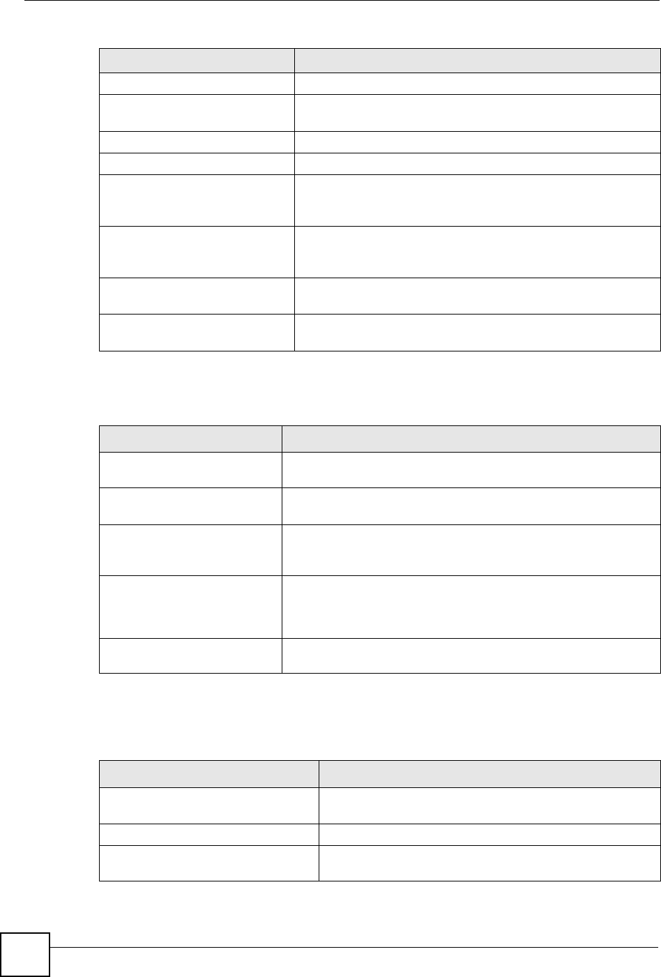
Chapter 21 Logs
NBG-460N User’s Guide
242
teardrop UDP The firewall detected an UDP teardrop attack.
teardrop ICMP (type:%d,
code:%d)
The firewall detected an ICMP teardrop attack. For type and code
details, see Table 104 on page 247.
illegal command TCP The firewall detected a TCP illegal command attack.
NetBIOS TCP The firewall detected a TCP NetBIOS attack.
ip spoofing - no routing
entry [TCP | UDP | IGMP |
ESP | GRE | OSPF]
The firewall classified a packet with no source routing entry as an
IP spoofing attack.
ip spoofing - no routing
entry ICMP (type:%d,
code:%d)
The firewall classified an ICMP packet with no source routing
entry as an IP spoofing attack.
vulnerability ICMP
(type:%d, code:%d)
The firewall detected an ICMP vulnerability attack. For type and
code details, see Table 104 on page 247.
traceroute ICMP (type:%d,
code:%d)
The firewall detected an ICMP traceroute attack. For type and
code details, see Table 104 on page 247.
Table 99 IPSec Logs
LOG MESSAGE DESCRIPTION
Discard REPLAY packet The router received and discarded a packet with an incorrect
sequence number.
Inbound packet
authentication failed
The router received a packet that has been altered. A third party may
have altered or tampered with the packet.
Receive IPSec packet,
but no corresponding
tunnel exists
The router dropped an inbound packet for which SPI could not find a
corresponding phase 2 SA.
Rule <%d> idle time out,
disconnect
The router dropped a connection that had outbound traffic and no
inbound traffic for a certain time period. You can use the "ipsec timer
chk_conn" CI command to set the time period. The default value is 2
minutes.
WAN IP changed to <IP> The router dropped all connections with the “MyIP” configured as
“0.0.0.0” when the WAN IP address changed.
Table 100 IKE Logs
LOG MESSAGE DESCRIPTION
Active connection allowed
exceeded
The IKE process for a new connection failed because the limit
of simultaneous phase 2 SAs has been reached.
Start Phase 2: Quick Mode Phase 2 Quick Mode has started.
Verifying Remote ID failed: The connection failed during IKE phase 2 because the router
and the peer’s Local/Remote Addresses don’t match.
Table 98 Attack Logs (continued)
LOG MESSAGE DESCRIPTION

Chapter 21 Logs
NBG-460N User’s Guide 243
Verifying Local ID failed: The connection failed during IKE phase 2 because the router
and the peer’s Local/Remote Addresses don’t match.
IKE Packet Retransmit The router retransmitted the last packet sent because there
was no response from the peer.
Failed to send IKE Packet An Ethernet error stopped the router from sending IKE
packets.
Too many errors! Deleting SA An SA was deleted because there were too many errors.
Phase 1 IKE SA process done The phase 1 IKE SA process has been completed.
Duplicate requests with the
same cookie
The router received multiple requests from the same peer
while still processing the first IKE packet from the peer.
IKE Negotiation is in process The router has already started negotiating with the peer for
the connection, but the IKE process has not finished yet.
No proposal chosen Phase 1 or phase 2 parameters don’t match. Please check all
protocols / settings. Ex. One device being configured for
3DES and the other being configured for DES causes the
connection to fail.
Local / remote IPs of
incoming request conflict
with rule <%d>
The security gateway is set to “0.0.0.0” and the router used
the peer’s “Local Address” as the router’s “Remote Address”.
This information conflicted with static rule #d; thus the
connection is not allowed.
Cannot resolve Secure Gateway
Addr for rule <%d>
The router couldn’t resolve the IP address from the domain
name that was used for the secure gateway address.
Peer ID: <peer id> <My remote
type> -<My local type>
The displayed ID information did not match between the two
ends of the connection.
vs. My Remote <My remote> -
<My remote>
The displayed ID information did not match between the two
ends of the connection.
vs. My Local <My local>-<My
local>
The displayed ID information did not match between the two
ends of the connection.
Send <packet> A packet was sent.
Recv <packet> IKE uses ISAKMP to transmit data. Each ISAKMP packet
contains many different types of payloads. All of them show in
the LOG. Refer to RFC2408 – ISAKMP for a list of all ISAKMP
payload types.
Recv <Main or Aggressive>
Mode request from <IP>
The router received an IKE negotiation request from the peer
address specified.
Send <Main or Aggressive>
Mode request to <IP>
The router started negotiation with the peer.
Invalid IP <Peer local> /
<Peer local>
The peer’s “Local IP Address” is invalid.
Remote IP <Remote IP> /
<Remote IP> conflicts
The security gateway is set to “0.0.0.0” and the router used
the peer’s “Local Address” as the router’s “Remote Address”.
This information conflicted with static rule #d; thus the
connection is not allowed.
Phase 1 ID type mismatch This router’s "Peer ID Type" is different from the peer IPSec
router's "Local ID Type".
Phase 1 ID content mismatch This router’s "Peer ID Content" is different from the peer
IPSec router's "Local ID Content".
Table 100 IKE Logs (continued)
LOG MESSAGE DESCRIPTION

Chapter 21 Logs
NBG-460N User’s Guide
244
No known phase 1 ID type
found
The router could not find a known phase 1 ID in the
connection attempt.
ID type mismatch. Local /
Peer: <Local ID type/Peer ID
type>
The phase 1 ID types do not match.
ID content mismatch The phase 1 ID contents do not match.
Configured Peer ID Content:
<Configured Peer ID Content>
The phase 1 ID contents do not match and the configured
"Peer ID Content" is displayed.
Incoming ID Content:
<Incoming Peer ID Content>
The phase 1 ID contents do not match and the incoming
packet's ID content is displayed.
Unsupported local ID Type:
<%d>
The phase 1 ID type is not supported by the router.
Build Phase 1 ID The router has started to build the phase 1 ID.
Adjust TCP MSS to%d The router automatically changed the TCP Maximum
Segment Size value after establishing a tunnel.
Rule <%d> input idle time
out, disconnect
The tunnel for the listed rule was dropped because there was
no inbound traffic within the idle timeout period.
XAUTH succeed! Username:
<Username>
The router used extended authentication to authenticate the
listed username.
XAUTH fail! Username:
<Username>
The router was not able to use extended authentication to
authenticate the listed username.
Rule[%d] Phase 1 negotiation
mode mismatch
The listed rule’s IKE phase 1 negotiation mode did not match
between the router and the peer.
Rule [%d] Phase 1 encryption
algorithm mismatch
The listed rule’s IKE phase 1 encryption algorithm did not
match between the router and the peer.
Rule [%d] Phase 1
authentication algorithm
mismatch
The listed rule’s IKE phase 1 authentication algorithm did not
match between the router and the peer.
Rule [%d] Phase 1
authentication method
mismatch
The listed rule’s IKE phase 1 authentication method did not
match between the router and the peer.
Rule [%d] Phase 1 key group
mismatch
The listed rule’s IKE phase 1 key group did not match
between the router and the peer.
Rule [%d] Phase 2 protocol
mismatch
The listed rule’s IKE phase 2 protocol did not match between
the router and the peer.
Rule [%d] Phase 2 encryption
algorithm mismatch
The listed rule’s IKE phase 2 encryption algorithm did not
match between the router and the peer.
Rule [%d] Phase 2
authentication algorithm
mismatch
The listed rule’s IKE phase 2 authentication algorithm did not
match between the router and the peer.
Rule [%d] Phase 2
encapsulation mismatch
The listed rule’s IKE phase 2 encapsulation did not match
between the router and the peer.
Rule [%d]> Phase 2 pfs
mismatch
The listed rule’s IKE phase 2 perfect forward secret (pfs)
setting did not match between the router and the peer.
Table 100 IKE Logs (continued)
LOG MESSAGE DESCRIPTION
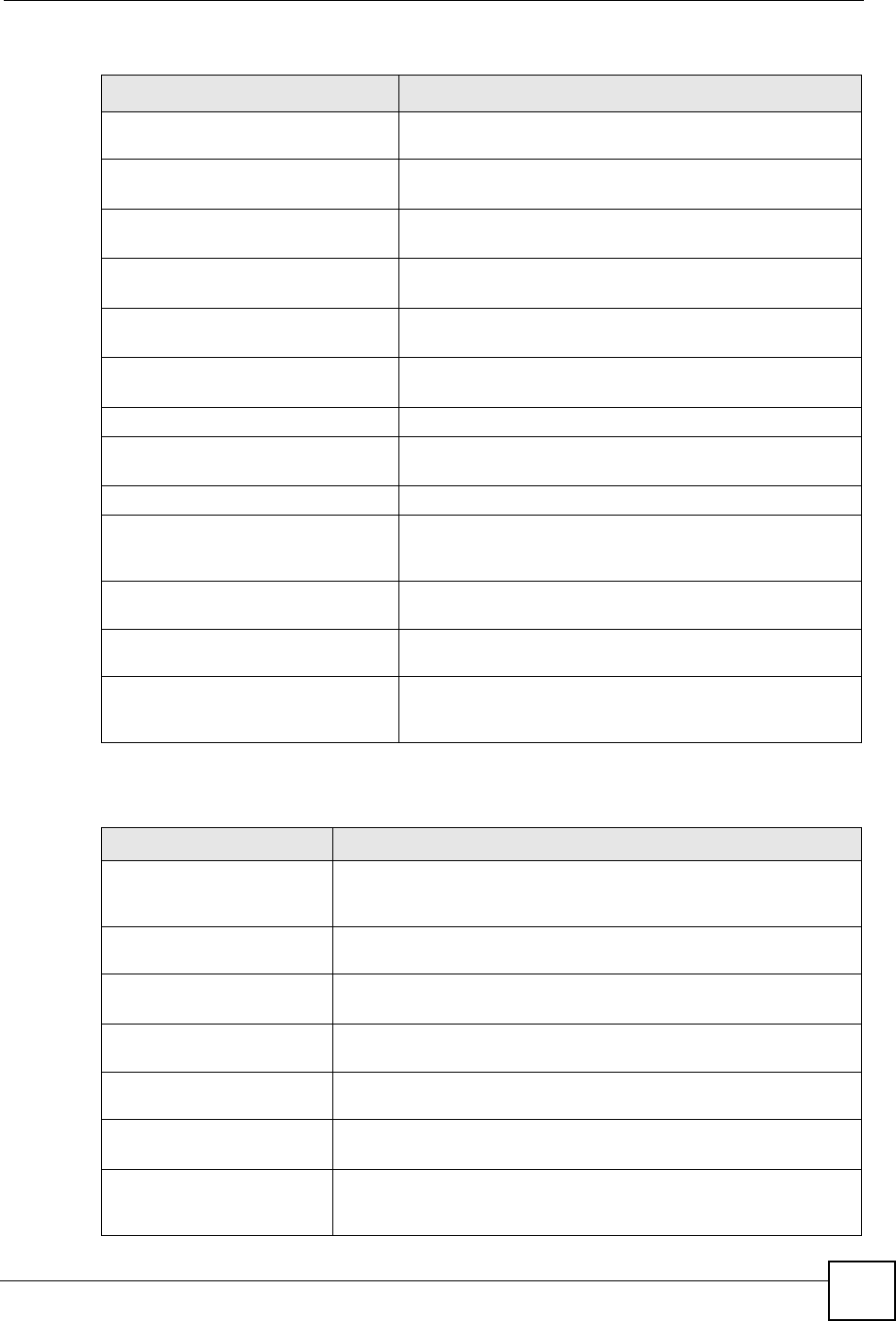
Chapter 21 Logs
NBG-460N User’s Guide 245
Rule [%d] Phase 1 ID mismatch The listed rule’s IKE phase 1 ID did not match between the
router and the peer.
Rule [%d] Phase 1 hash
mismatch
The listed rule’s IKE phase 1 hash did not match between the
router and the peer.
Rule [%d] Phase 1 preshared
key mismatch
The listed rule’s IKE phase 1 pre-shared key did not match
between the router and the peer.
Rule [%d] Tunnel built
successfully
The listed rule’s IPSec tunnel has been built successfully.
Rule [%d] Peer's public key
not found
The listed rule’s IKE phase 1 peer’s public key was not found.
Rule [%d] Verify peer's
signature failed
The listed rule’s IKE phase 1verification of the peer’s
signature failed.
Rule [%d] Sending IKE request IKE sent an IKE request for the listed rule.
Rule [%d] Receiving IKE
request
IKE received an IKE request for the listed rule.
Swap rule to rule [%d] The router changed to using the listed rule.
Rule [%d] Phase 1 key length
mismatch
The listed rule’s IKE phase 1 key length (with the AES
encryption algorithm) did not match between the router and
the peer.
Rule [%d] phase 1 mismatch The listed rule’s IKE phase 1 did not match between the router
and the peer.
Rule [%d] phase 2 mismatch The listed rule’s IKE phase 2 did not match between the router
and the peer.
Rule [%d] Phase 2 key length
mismatch
The listed rule’s IKE phase 2 key lengths (with the AES
encryption algorithm) did not match between the router and
the peer.
Table 101 PKI Logs
LOG MESSAGE DESCRIPTION
Enrollment successful The SCEP online certificate enrollment was successful. The
Destination field records the certification authority server IP address
and port.
Enrollment failed The SCEP online certificate enrollment failed. The Destination field
records the certification authority server’s IP address and port.
Failed to resolve
<SCEP CA server url>
The SCEP online certificate enrollment failed because the certification
authority server’s address cannot be resolved.
Enrollment successful The CMP online certificate enrollment was successful. The Destination
field records the certification authority server’s IP address and port.
Enrollment failed The CMP online certificate enrollment failed. The Destination field
records the certification authority server’s IP address and port.
Failed to resolve <CMP
CA server url>
The CMP online certificate enrollment failed because the certification
authority server’s IP address cannot be resolved.
Rcvd ca cert: <subject
name>
The router received a certification authority certificate, with subject
name as recorded, from the LDAP server whose IP address and port
are recorded in the Source field.
Table 100 IKE Logs (continued)
LOG MESSAGE DESCRIPTION
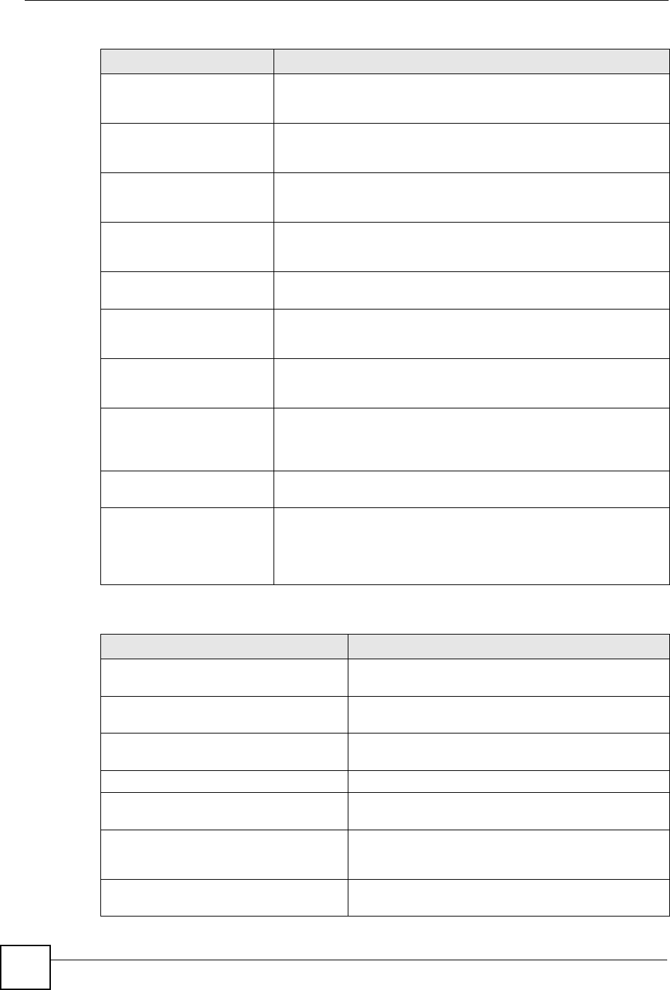
Chapter 21 Logs
NBG-460N User’s Guide
246
Rcvd user cert:
<subject name>
The router received a user certificate, with subject name as recorded,
from the LDAP server whose IP address and port are recorded in the
Source field.
Rcvd CRL <size>:
<issuer name>
The router received a CRL (Certificate Revocation List), with size and
issuer name as recorded, from the LDAP server whose IP address and
port are recorded in the Source field.
Rcvd ARL <size>:
<issuer name>
The router received an ARL (Authority Revocation List), with size and
issuer name as recorded, from the LDAP server whose address and
port are recorded in the Source field.
Failed to decode the
received ca cert
The router received a corrupted certification authority certificate from
the LDAP server whose address and port are recorded in the Source
field.
Failed to decode the
received user cert
The router received a corrupted user certificate from the LDAP server
whose address and port are recorded in the Source field.
Failed to decode the
received CRL
The router received a corrupted CRL (Certificate Revocation List) from
the LDAP server whose address and port are recorded in the Source
field.
Failed to decode the
received ARL
The router received a corrupted ARL (Authority Revocation List) from
the LDAP server whose address and port are recorded in the Source
field.
Rcvd data <size> too
large! Max size
allowed: <max size>
The router received directory data that was too large (the size is listed)
from the LDAP server whose address and port are recorded in the
Source field. The maximum size of directory data that the router allows
is also recorded.
Cert trusted: <subject
name>
The router has verified the path of the certificate with the listed subject
name.
Due to <reason codes>,
cert not trusted:
<subject name>
Due to the reasons listed, the certificate with the listed subject name
has not passed the path verification. The recorded reason codes are
only approximate reasons for not trusting the certificate. Please see
Table 104 on page 247 for the corresponding descriptions of the
codes.
Table 102 802.1X Logs
LOG MESSAGE DESCRIPTION
Local User Database accepts
user.
A user was authenticated by the local user database.
Local User Database reports user
credential error.
A user was not authenticated by the local user database
because of an incorrect user password.
Local User Database does not
find user`s credential.
A user was not authenticated by the local user database
because the user is not listed in the local user database.
RADIUS accepts user. A user was authenticated by the RADIUS Server.
RADIUS rejects user. Pls check
RADIUS Server.
A user was not authenticated by the RADIUS Server.
Please check the RADIUS Server.
Local User Database does not
support authentication method.
The local user database only supports the EAP-MD5
method. A user tried to use another authentication
method and was not authenticated.
User logout because of session
timeout expired.
The router logged out a user whose session expired.
Table 101 PKI Logs (continued)
LOG MESSAGE DESCRIPTION

Chapter 21 Logs
NBG-460N User’s Guide 247
User logout because of user
deassociation.
The router logged out a user who ended the session.
User logout because of no
authentication response from
user.
The router logged out a user from which there was no
authentication response.
User logout because of idle
timeout expired.
The router logged out a user whose idle timeout period
expired.
User logout because of user
request.
A user logged out.
Local User Database does not
support authentication method.
A user tried to use an authentication method that the
local user database does not support (it only supports
EAP-MD5).
No response from RADIUS. Pls
check RADIUS Server.
There is no response message from the RADIUS server,
please check the RADIUS server.
Use Local User Database to
authenticate user.
The local user database is operating as the
authentication server.
Use RADIUS to authenticate user. The RADIUS server is operating as the authentication
server.
No Server to authenticate user. There is no authentication server to authenticate a user.
Local User Database does not
find user`s credential.
A user was not authenticated by the local user database
because the user is not listed in the local user database.
Table 103 ACL Setting Notes
PACKET DIRECTION DIRECTION DESCRIPTION
(L to W) LAN to WAN ACL set for packets traveling from the LAN to the WAN.
(W to L) WAN to LAN ACL set for packets traveling from the WAN to the LAN.
(L to L/P) LAN to LAN/NBG-
460N ACL set for packets traveling from the LAN to the LAN or
the NBG-460N.
(W to W/P) WAN to WAN/
NBG-460N ACL set for packets traveling from the WAN to the WAN
or the NBG-460N.
Table 104 ICMP Notes
TYPE CODE DESCRIPTION
0Echo Reply
0Echo reply message
3Destination Unreachable
0Net unreachable
1Host unreachable
2Protocol unreachable
3Port unreachable
4A packet that needed fragmentation was dropped because it was set to Don't
Fragment (DF)
Table 102 802.1X Logs (continued)
LOG MESSAGE DESCRIPTION

Chapter 21 Logs
NBG-460N User’s Guide
248
5Source route failed
4Source Quench
0A gateway may discard internet datagrams if it does not have the buffer space
needed to queue the datagrams for output to the next network on the route to
the destination network.
5Redirect
0Redirect datagrams for the Network
1Redirect datagrams for the Host
2Redirect datagrams for the Type of Service and Network
3Redirect datagrams for the Type of Service and Host
8Echo
0Echo message
11 Time Exceeded
0Time to live exceeded in transit
1Fragment reassembly time exceeded
12 Parameter Problem
0Pointer indicates the error
13 Timestamp
0Timestamp request message
14 Timestamp Reply
0Timestamp reply message
15 Information Request
0Information request message
16 Information Reply
0Information reply message
Table 105 Syslog Logs
LOG MESSAGE DESCRIPTION
<Facility*8 + Severity>Mon dd
hr:mm:ss hostname
src="<srcIP:srcPort>"
dst="<dstIP:dstPort>"
msg="<msg>" note="<note>"
devID="<mac address last three
numbers>" cat="<category>
"This message is sent by the system ("RAS" displays as
the system name if you haven’t configured one) when the
router generates a syslog. The facility is defined in the web
MAIN MENU->LOGS->Log Settings page. The severity is
the log’s syslog class. The definition of messages and
notes are defined in the various log charts throughout this
appendix. The “devID” is the last three characters of the
MAC address of the router’s LAN port. The “cat” is the
same as the category in the router’s logs.
Table 104 ICMP Notes (continued)
TYPE CODE DESCRIPTION

Chapter 21 Logs
NBG-460N User’s Guide 249
The following table shows RFC-2408 ISAKMP payload types that the log displays. Please
refer to the RFC for detailed information on each type.
Table 106 RFC-2408 ISAKMP Payload Types
LOG DISPLAY PAYLOAD TYPE
SA Security Association
PROP Proposal
TRANS Transform
KE Key Exchange
ID Identification
CER Certificate
CER_REQ Certificate Request
HASH Hash
SIG Signature
NONCE Nonce
NOTFY Notification
DEL Delete
VID Vendor ID

Chapter 21 Logs
NBG-460N User’s Guide
250