ZyXEL Communications X550NHV2 High-gain Wireless N Gigabit Router User Manual 1
ZyXEL Communications Corporation High-gain Wireless N Gigabit Router 1
Contents
- 1. User Manual 1
- 2. User Manual 2
- 3. User Manual 3
User Manual 1

www.zyxel.com
NBG-460N
Wireless N Gigabit Router
User’s Guide
Version 3.60
3/2008
Edition 1
DEFAULT LOGIN
IP Address http://192.168.1.1
Password 1234

About This User's Guide
NBG-460N User’s Guide 3
About This User's Guide
Intended Audience
This manual is intended for people who want to configure the NBG-460N using the web
configurator. You should have at least a basic knowledge of TCP/IP networking concepts and
topology.
Related Documentation
• Quick Start Guide
The Quick Start Guide is designed to help you get up and running right away. It contains
information on setting up your network and configuring for Internet access.
• Supporting Disk
Refer to the included CD for support documents.
• ZyXEL Web Site
Please refer to www.zyxel.com for additional support documentation and product
certifications.
User Guide Feedback
Help us help you. Send all User Guide-related comments, questions or suggestions for
improvement to the following address, or use e-mail instead. Thank you!
The Technical Writing Team,
ZyXEL Communications Corp.,
6 Innovation Road II,
Science-Based Industrial Park,
Hsinchu, 300, Taiwan.
E-mail: techwriters@zyxel.com.tw

Document Conventions
NBG-460N User’s Guide
4
Document Conventions
Warnings and Notes
These are how warnings and notes are shown in this User’s Guide.
1Warnings tell you about things that could harm you or your device.
"Notes tell you other important information (for example, other things you may
need to configure or helpful tips) or recommendations.
Syntax Conventions
• The NBG-460N may be referred to as the “NBG-460N”, the “device”, the “product” or the
“system” in this User’s Guide.
• Product labels, screen names, field labels and field choices are all in bold font.
• A key stroke is denoted by square brackets and uppercase text, for example, [ENTER]
means the “enter” or “return” key on your keyboard.
• “Enter” means for you to type one or more characters and then press the [ENTER] key.
“Select” or “choose” means for you to use one of the predefined choices.
• A right angle bracket ( > ) within a screen name denotes a mouse click. For example,
Maintenance > Log > Log Setting means you first click Maintenance in the navigation
panel, then the Log sub menu and finally the Log Setting tab to get to that screen.
• Units of measurement may denote the “metric” value or the “scientific” value. For
example, “k” for kilo may denote “1000” or “1024”, “M” for mega may denote “1000000”
or “1048576” and so on.
• “e.g.,” is a shorthand for “for instance”, and “i.e.,” means “that is” or “in other words”.
Document Conventions
NBG-460N User’s Guide 5
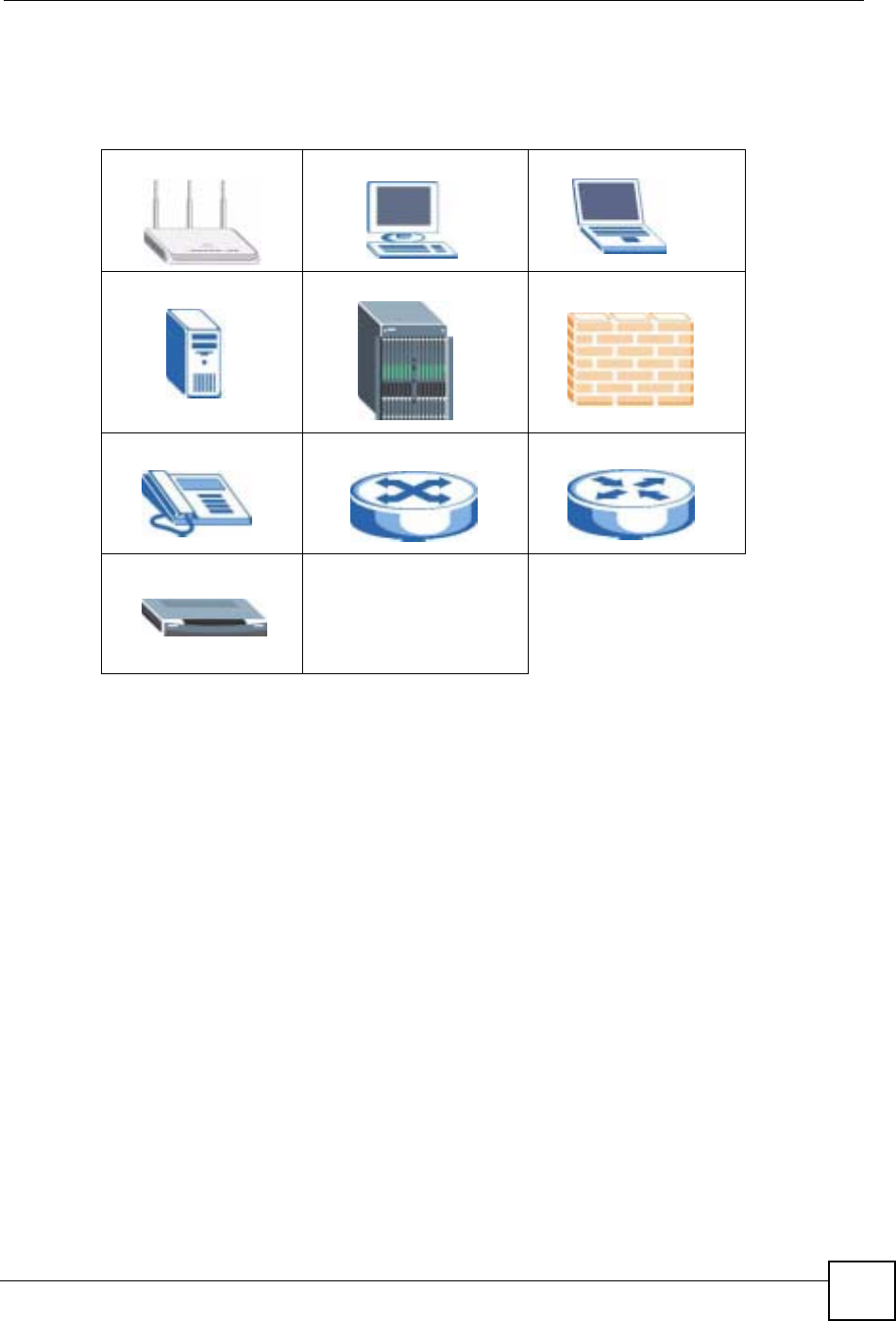
Icons Used in Figures
Figures in this User’s Guide may use the following generic icons. The NBG-460N icon is not
an exact representation of your device.
NBG-460N Computer Notebook computer
Server DSLAM Firewall
Telephone Switch Router
Modem

Safety Warnings
NBG-460N User’s Guide
6
Safety Warnings
1For your safety, be sure to read and follow all warning notices and instructions.
• Do NOT use this product near water, for example, in a wet basement or near a swimming
pool.
• Do NOT expose your device to dampness, dust or corrosive liquids.
• Do NOT store things on the device.
• Do NOT install, use, or service this device during a thunderstorm. There is a remote risk
of electric shock from lightning.
• Connect ONLY suitable accessories to the device.
• Do NOT open the device or unit. Opening or removing covers can expose you to
dangerous high voltage points or other risks. ONLY qualified service personnel should
service or disassemble this device. Please contact your vendor for further information.
• Make sure to connect the cables to the correct ports.
• Place connecting cables carefully so that no one will step on them or stumble over them.
• Always disconnect all cables from this device before servicing or disassembling.
• Use ONLY an appropriate power adaptor or cord for your device.
• Connect the power adaptor or cord to the right supply voltage (for example, 110V AC in
North America or 230V AC in Europe).
• Do NOT allow anything to rest on the power adaptor or cord and do NOT place the
product where anyone can walk on the power adaptor or cord.
• Do NOT use the device if the power adaptor or cord is damaged as it might cause
electrocution.
• If the power adaptor or cord is damaged, remove it from the power outlet.
• Do NOT attempt to repair the power adaptor or cord. Contact your local vendor to order a
new one.
• Do not use the device outside, and make sure all the connections are indoors. There is a
remote risk of electric shock from lightning.
• Do NOT obstruct the device ventilation slots, as insufficient airflow may harm your
device.
• Antenna Warning! This device meets ETSI and FCC certification requirements when
using the included antenna(s). Only use the included antenna(s).
• If you wall mount your device, make sure that no electrical lines, gas or water pipes will
be damaged.
This product is recyclable. Dispose of it properly.

Safety Warnings
NBG-460N User’s Guide 7

Safety Warnings
NBG-460N User’s Guide
8

Contents Overview
NBG-460N User’s Guide 9
Contents Overview
Introduction ............................................................................................................................29
Getting to Know Your NBG-460N .............................................................................................. 31
The WPS Button ........................................................................................................................ 35
Introducing the Web Configurator .............................................................................................. 37
Connection Wizard .................................................................................................................... 49
AP Mode .................................................................................................................................... 65
Tutorials ..................................................................................................................................... 73
Network ...................................................................................................................................87
Wireless LAN ............................................................................................................................. 89
WAN ........................................................................................................................................ 117
LAN .......................................................................................................................................... 127
DHCP ...................................................................................................................................... 133
Network Address Translation (NAT) ........................................................................................ 137
Dynamic DNS .......................................................................................................................... 147
Security .................................................................................................................................151
Firewall .................................................................................................................................... 153
Content Filtering ...................................................................................................................... 161
IPSec VPN ............................................................................................................................... 165
Management .........................................................................................................................193
Static Route Screens ............................................................................................................... 195
Bandwidth Management .......................................................................................................... 199
Remote Management ..............................................................................................................209
Universal Plug-and-Play (UPnP) ............................................................................................. 215
Maintenance and Troubleshooting ....................................................................................227
System ..................................................................................................................................... 229
Logs ......................................................................................................................................... 233
Tools ........................................................................................................................................ 251
Configuration Mode ................................................................................................................. 257
Sys Op Mode ........................................................................................................................... 259
Language ................................................................................................................................. 263
Troubleshooting ....................................................................................................................... 265
Appendices and Index .........................................................................................................271

Contents Overview
NBG-460N User’s Guide
10

Table of Contents
NBG-460N User’s Guide 11
Table of Contents
About This User's Guide ..........................................................................................................3
Document Conventions............................................................................................................4
Safety Warnings........................................................................................................................6
Contents Overview ...................................................................................................................9
Table of Contents....................................................................................................................11
List of Figures .........................................................................................................................19
List of Tables...........................................................................................................................25
Part I: Introduction................................................................................. 29
Chapter 1
Getting to Know Your NBG-460N ..........................................................................................31
1.1 Overview .............................................................................................................................. 31
1.2 Router Mode ........................................................................................................................ 31
1.3 AP Mode .............................................................................................................................. 32
1.4 Router Features vs. AP Features ........................................................................................ 32
1.5 Ways to Manage the NBG-460N ......................................................................................... 33
1.6 Good Habits for Managing the NBG-460N .......................................................................... 33
1.7 LEDs .................................................................................................................................... 33
Chapter 2
The WPS Button......................................................................................................................35
2.1 Overview .............................................................................................................................. 35
Chapter 3
Introducing the Web Configurator ........................................................................................37
3.1 Web Configurator Overview ................................................................................................ 37
3.2 Accessing the Web Configurator ......................................................................................... 37
3.3 Resetting the NBG-460N .....................................................................................................39
3.3.1 Procedure to Use the Reset Button ........................................................................... 39
3.4 Navigating the Web Configurator ..................................................................................... 39
3.5 The Status Screen in Router Mode ..................................................................................... 39
3.5.1 Navigation Panel ........................................................................................................ 42

Table of Contents
NBG-460N User’s Guide
12
3.5.2 Summary: Any IP Table ............................................................................................. 44
3.5.3 Summary: Bandwidth Management Monitor ........................................................... 44
3.5.4 Summary: DHCP Table ........................................................................................... 45
3.5.5 Summary: Packet Statistics .................................................................................... 46
3.5.6 Summary: VPN Monitor ............................................................................................. 47
3.5.7 Summary: Wireless Station Status ......................................................................... 47
Chapter 4
Connection Wizard .................................................................................................................49
4.1 Wizard Setup ....................................................................................................................... 49
4.2 Connection Wizard: STEP 1: System Information ............................................................... 50
4.2.1 System Name ............................................................................................................. 50
4.2.2 Domain Name ............................................................................................................ 51
4.3 Connection Wizard: STEP 2: Wireless LAN ........................................................................ 51
4.3.1 Basic (WEP) Security ................................................................................................. 53
4.3.2 Extend (WPA-PSK or WPA2-PSK) Security .............................................................. 54
4.4 Connection Wizard: STEP 3: Internet Configuration ........................................................... 54
4.4.1 Ethernet Connection .................................................................................................. 55
4.4.2 PPPoE Connection .................................................................................................... 55
4.4.3 PPTP Connection ....................................................................................................... 56
4.4.4 Your IP Address ......................................................................................................... 58
4.4.5 WAN IP Address Assignment .................................................................................... 58
4.4.6 IP Address and Subnet Mask ..................................................................................... 59
4.4.7 DNS Server Address Assignment .............................................................................. 59
4.4.8 WAN IP and DNS Server Address Assignment ......................................................... 60
4.4.9 WAN MAC Address .................................................................................................... 61
4.5 Connection Wizard: STEP 4: Bandwidth management ....................................................... 62
4.6 Connection Wizard Complete .............................................................................................. 62
Chapter 5
AP Mode...................................................................................................................................65
5.1 AP Mode Overview .............................................................................................................. 65
5.2 Setting your NBG-460N to AP Mode ................................................................................... 65
5.3 The Status Screen in AP Mode ........................................................................................... 66
5.3.1 Navigation Panel ........................................................................................................ 68
5.4 Configuring Your Settings .................................................................................................... 69
5.4.1 LAN Settings .............................................................................................................. 69
5.4.2 WLAN and Maintenance Settings .............................................................................. 71
5.5 Logging in to the Web Configurator in AP Mode ................................................................. 71
Chapter 6
Tutorials...................................................................................................................................73
6.1 Wireless Tutorials ................................................................................................................ 73

Table of Contents
NBG-460N User’s Guide 13
6.1.1 How to Connect to the Internet from an AP ............................................................... 73
6.1.2 Configure Wireless Security Using WPS on both your NBG-460N and Wireless Client
73
6.1.3 Enable and Configure Wireless Security without WPS on your NBG-460N .............. 76
6.1.4 Configure Your Notebook ........................................................................................... 78
6.2 Site-To-Site VPN Tunnel Tutorial ........................................................................................ 80
6.2.1 Configuring Bob’s NBG-460N VPN Settings .............................................................. 81
6.2.2 Configuring Jack’s NBG-460N VPN Settings ............................................................. 83
6.2.3 Checking the VPN Connection ................................................................................... 84
Part II: Network....................................................................................... 87
Chapter 7
Wireless LAN...........................................................................................................................89
7.1 Wireless Network Overview ................................................................................................. 89
7.2 Wireless Security Overview .................................................................................................90
7.2.1 SSID ........................................................................................................................... 90
7.2.2 MAC Address Filter .................................................................................................... 90
7.2.3 User Authentication .................................................................................................... 90
7.2.4 Encryption .................................................................................................................. 91
7.3 Roaming .............................................................................................................................. 92
7.3.1 Requirements for Roaming ........................................................................................ 93
7.4 Quality of Service ................................................................................................................ 93
7.4.1 WMM QoS ..................................................................................................................94
7.5 General Wireless LAN Screen ............................................................................................ 94
7.5.1 No Security ................................................................................................................. 96
7.5.2 WEP Encryption ......................................................................................................... 96
7.5.3 WPA-PSK/WPA2-PSK ............................................................................................... 98
7.5.4 WPA/WPA2 ................................................................................................................ 99
7.6 MAC Filter .......................................................................................................................... 101
7.7 Wireless LAN Advanced Screen ....................................................................................... 102
7.8 Quality of Service (QoS) Screen ....................................................................................... 103
7.8.1 Application Priority Configuration ............................................................................. 105
7.9 WiFi Protected Setup ......................................................................................................... 106
7.9.1 WPS Screen ............................................................................................................. 106
7.9.2 WPS Station Screen ................................................................................................ 107
7.9.3 Scheduling ...............................................................................................................107
7.10 iPod Touch Web Configurator ......................................................................................... 108
7.10.1 Login Screen .......................................................................................................... 109
7.10.2 System Status ........................................................................................................ 110
7.10.3 WPS in Progress .................................................................................................... 112
7.10.4 Port Forwarding ...................................................................................................... 113

Table of Contents
NBG-460N User’s Guide
14
7.11 Accessing the iPod Touch Web Configurator .................................................................. 114
7.11.1 Accessing the iPod Touch Web Configurator ........................................................ 115
Chapter 8
WAN .......................................................................................................................................117
8.1 WAN Overview .................................................................................................................. 117
8.2 WAN MAC Address ........................................................................................................... 117
8.3 Multicast ............................................................................................................................ 117
8.4 Internet Connection ........................................................................................................... 118
8.4.1 Ethernet Encapsulation ............................................................................................ 118
8.4.2 PPPoE Encapsulation .............................................................................................. 119
8.4.3 PPTP Encapsulation ................................................................................................ 122
8.5 Advanced WAN Screen ..................................................................................................... 125
Chapter 9
LAN.........................................................................................................................................127
9.1 LAN Overview .................................................................................................................... 127
9.1.1 IP Pool Setup ........................................................................................................... 127
9.1.2 System DNS Servers ............................................................................................... 127
9.2 LAN TCP/IP ....................................................................................................................... 127
9.2.1 Factory LAN Defaults ............................................................................................... 127
9.2.2 IP Address and Subnet Mask ................................................................................... 128
9.2.3 Multicast ................................................................................................................... 128
9.2.4 Any IP ....................................................................................................................... 128
9.3 LAN IP Screen ................................................................................................................... 130
9.4 LAN IP Alias ..................................................................................................................... 130
9.5 Advanced LAN Screen ...................................................................................................... 131
Chapter 10
DHCP......................................................................................................................................133
10.1 DHCP .............................................................................................................................. 133
10.2 DHCP General Screen .................................................................................................... 133
10.3 DHCP Advanced Screen .............................................................................................. 134
10.4 Client List Screen ............................................................................................................ 135
Chapter 11
Network Address Translation (NAT) ...................................................................................137
11.1 NAT Overview .............................................................................................................. 137
11.2 Using NAT ....................................................................................................................... 137
11.2.1 Port Forwarding: Services and Port Numbers ........................................................ 137
11.2.2 Configuring Servers Behind Port Forwarding Example .......................................... 138
11.3 General NAT Screen ....................................................................................................... 138
11.4 NAT Application Screen ................................................................................................ 139

Table of Contents
NBG-460N User’s Guide 15
11.4.1 Game List Example ................................................................................................ 141
11.5 Trigger Port Forwarding ...................................................................................................142
11.5.1 Trigger Port Forwarding Example .......................................................................... 142
11.5.2 Two Points To Remember About Trigger Ports ..................................................... 143
11.6 NAT Advanced Screen .................................................................................................... 143
Chapter 12
Dynamic DNS ........................................................................................................................147
12.1 Dynamic DNS Introduction ............................................................................................. 147
12.1.1 DynDNS Wildcard .................................................................................................. 147
12.2 Dynamic DNS Screen .................................................................................................... 147
Part III: Security.................................................................................... 151
Chapter 13
Firewall...................................................................................................................................153
13.1 Introduction to ZyXEL’s Firewall .................................................................................... 153
13.1.1 What is a Firewall? ................................................................................................. 153
13.1.2 Stateful Inspection Firewall .................................................................................... 153
13.1.3 About the NBG-460N Firewall ................................................................................ 153
13.1.4 Guidelines For Enhancing Security With Your Firewall .......................................... 154
13.2 Triangle Routes ............................................................................................................... 154
13.2.1 Triangle Routes and IP Alias .................................................................................. 154
13.3 General Firewall Screen ............................................................................................... 155
13.4 Services Screen ............................................................................................................. 156
13.4.1 The Add Firewall Rule Screen ............................................................................... 157
Chapter 14
Content Filtering ...................................................................................................................161
14.1 Introduction to Content Filtering ...................................................................................... 161
14.2 Restrict Web Features .....................................................................................................161
14.3 Days and Times ............................................................................................................... 161
14.4 Filter Screen .................................................................................................................... 161
14.5 Schedule .......................................................................................................................... 163
14.6 Customizing Keyword Blocking URL Checking ............................................................... 164
14.6.1 Domain Name or IP Address URL Checking ......................................................... 164
14.6.2 Full Path URL Checking ......................................................................................... 164
14.6.3 File Name URL Checking ....................................................................................... 164
Chapter 15
IPSec VPN..............................................................................................................................165

Table of Contents
NBG-460N User’s Guide
16
15.1 IPSec VPN Overview ....................................................................................................... 165
15.1.1 What You Can Do in the IPSec VPN Screens ....................................................... 165
15.1.2 What You Need To Know About IPSec VPN ......................................................... 166
15.1.3 IKE SA (IKE Phase 1) Overview ............................................................................ 166
15.1.4 IPSec SA (IKE Phase 2) Overview ...................................................................... 167
15.2 The General Screen ........................................................................................................167
15.2.1 VPN Rule Setup (Basic) ......................................................................................... 168
15.2.2 VPN Rule Setup (Advanced) .................................................................................. 173
15.2.3 VPN Rule Setup (Manual) ...................................................................................... 179
15.3 The SA Monitor Screen ................................................................................................... 184
15.4 VPN and Remote Management ....................................................................................... 185
15.5 IPSec VPN Technical Reference ..................................................................................... 186
Part IV: Management ........................................................................... 193
Chapter 16
Static Route Screens............................................................................................................195
16.1 Static Route Overview .....................................................................................................195
16.2 IP Static Route Screen ....................................................................................................195
16.2.1 Static Route Setup Screen ................................................................................... 196
Chapter 17
Bandwidth Management.......................................................................................................199
17.1 Bandwidth Management Overview ................................................................................. 199
17.2 Application-based Bandwidth Management .................................................................... 199
17.3 Subnet-based Bandwidth Management .......................................................................... 199
17.4 Application and Subnet-based Bandwidth Management ................................................. 200
17.5 Bandwidth Management Priorities ................................................................................... 200
17.6 Predefined Bandwidth Management Services ................................................................. 201
17.6.1 Services and Port Numbers ................................................................................... 201
17.7 Default Bandwidth Management Classes and Priorities .................................................. 202
17.8 Bandwidth Management General Configuration ............................................................. 202
17.9 Bandwidth Management Advanced Configuration ......................................................... 203
17.9.1 Rule Configuration with the Pre-defined Service ................................................ 205
17.9.2 Rule Configuration: User Defined Service Rule Configuration ............................ 205
17.10 Bandwidth Management Monitor ................................................................................ 206
Chapter 18
Remote Management............................................................................................................209
18.1 Remote Management Overview ...................................................................................... 209
18.1.1 Remote Management Limitations .......................................................................... 209

Table of Contents
NBG-460N User’s Guide 17
18.1.2 Remote Management and NAT ............................................................................. 210
18.1.3 System Timeout .................................................................................................... 210
18.2 WWW Screen ............................................................................................................... 210
18.3 Telnet ............................................................................................................................... 211
18.4 Telnet Screen .................................................................................................................. 211
18.5 FTP Screen ..................................................................................................................... 212
18.6 DNS Screen .................................................................................................................. 212
Chapter 19
Universal Plug-and-Play (UPnP)..........................................................................................215
19.1 Introducing Universal Plug and Play ............................................................................... 215
19.1.1 How do I know if I'm using UPnP? ......................................................................... 215
19.1.2 NAT Traversal ........................................................................................................ 215
19.1.3 Cautions with UPnP ............................................................................................... 215
19.2 UPnP and ZyXEL ............................................................................................................216
19.3 UPnP Screen ................................................................................................................... 216
19.4 Installing UPnP in Windows Example .............................................................................. 217
Part V: Maintenance and Troubleshooting........................................ 227
Chapter 20
System ...................................................................................................................................229
20.1 System Overview ............................................................................................................. 229
20.2 System General Screen ................................................................................................. 229
20.3 Time Setting Screen ........................................................................................................ 230
Chapter 21
Logs .......................................................................................................................................233
21.1 View Log ......................................................................................................................... 233
21.2 Log Settings ..................................................................................................................... 234
21.3 Log Descriptions .............................................................................................................. 237
Chapter 22
Tools ......................................................................................................................................251
22.1 Firmware Upload Screen ................................................................................................. 251
22.2 Configuration Screen ....................................................................................................... 252
22.2.1 Backup Configuration ............................................................................................. 253
22.2.2 Restore Configuration ............................................................................................ 253
22.2.3 Back to Factory Defaults ........................................................................................ 254
22.3 Restart Screen ................................................................................................................. 254
22.4 Wake On LAN .................................................................................................................. 255

Table of Contents
NBG-460N User’s Guide
18
Chapter 23
Configuration Mode..............................................................................................................257
Chapter 24
Sys Op Mode .........................................................................................................................259
24.1 Overview .......................................................................................................................... 259
24.1.1 Router .................................................................................................................... 259
24.1.2 AP .......................................................................................................................... 259
24.2 Selecting System Operation Mode .................................................................................. 260
Chapter 25
Language...............................................................................................................................263
25.1 Language Screen ............................................................................................................ 263
Chapter 26
Troubleshooting....................................................................................................................265
26.1 Power, Hardware Connections, and LEDs ...................................................................... 265
26.2 NBG-460N Access and Login .......................................................................................... 266
26.3 Internet Access ................................................................................................................ 268
26.4 Resetting the NBG-460N to Its Factory Defaults ............................................................. 269
26.5 Wireless Router/AP Troubleshooting .............................................................................. 269
26.6 Advanced Features .........................................................................................................270
Part VI: Appendices and Index ........................................................... 271
Appendix A Product Specifications and Wall-Mounting Instructions....................................273
Appendix B Pop-up Windows, JavaScripts and Java Permissions......................................279
Appendix C IP Addresses and Subnetting ...........................................................................285
Appendix D Setting up Your Computer’s IP Address ...........................................................293
26.6.1 Verifying Settings ................................................................................................... 308
Appendix E Wireless LANs ..................................................................................................309
26.6.2 WPA(2)-PSK Application Example ......................................................................... 318
26.6.3 WPA(2) with RADIUS Application Example ........................................................... 318
Appendix F Services ............................................................................................................321
Appendix G Legal Information..............................................................................................325
Appendix H Customer Support.............................................................................................329
Index.......................................................................................................................................335

List of Figures
NBG-460N User’s Guide 19
List of Figures
Figure 1 Secure Wireless Internet Access in Router Mode ................................................................... 31
Figure 2 Wireless Internet Access in AP Mode ..................................................................................... 32
Figure 3 Front Panel ............................................................................................................................... 33
Figure 4 Change Password Screen ........................................................................................................ 38
Figure 5 Selecting the setup mode ....................................................................................................... 39
Figure 6 Web Configurator Status Screen ............................................................................................. 40
Figure 7 Any IP Table ............................................................................................................................ 44
Figure 8 Summary: BW MGMT Monitor ................................................................................................. 45
Figure 9 Summary: DHCP Table ............................................................................................................ 45
Figure 10 Summary: Packet Statistics ................................................................................................... 46
Figure 11 Summary: VPN Monitor .......................................................................................................... 47
Figure 12 Summary: Wireless Association List ...................................................................................... 47
Figure 13 Select Wizard or Advanced Mode .......................................................................................... 49
Figure 14 Select a Language ................................................................................................................. 50
Figure 15 Welcome to the Connection Wizard ....................................................................................... 50
Figure 16 Wizard Step 1: System Information ........................................................................................ 51
Figure 17 Wizard Step 2: Wireless LAN ................................................................................................. 52
Figure 18 Wizard Step 2: Basic (WEP) Security .................................................................................... 53
Figure 19 Wizard Step 2: Extend (WPA-PSK or WPA2-PSK) Security .................................................. 54
Figure 20 Wizard Step 3: ISP Parameters. ............................................................................................ 55
Figure 21 Wizard Step 3: Ethernet Connection ...................................................................................... 55
Figure 22 Wizard Step 3: PPPoE Connection ........................................................................................ 56
Figure 23 Wizard Step 3: PPTP Connection .......................................................................................... 57
Figure 24 Wizard Step 3: Your IP Address ............................................................................................. 58
Figure 25 Wizard Step 3: WAN IP and DNS Server Addresses ............................................................. 60
Figure 26 Wizard Step 3: WAN MAC Address .......................................................................................61
Figure 27 Wizard Step 4: Bandwidth Management ............................................................................... 62
Figure 28 Connection Wizard Save ....................................................................................................... 63
Figure 29 Connection Wizard Complete ................................................................................................. 63
Figure 30 Wireless Internet Access in AP Mode ................................................................................... 65
Figure 31 Maintenance > Sys OP Mode > General ................................................................................ 66
Figure 32 Status: AP Mode ................................................................................................................... 66
Figure 33 Menu: AP Mode ...................................................................................................................... 68
Figure 34 Network > LAN > IP ............................................................................................................. 70
Figure 35 Wireless AP Connection to the Internet ................................................................................. 73
Figure 36 Example WPS Process: PBC Method .................................................................................... 75
Figure 37 Example WPS Process: PIN Method ..................................................................................... 76
Figure 38 Network > Wireless LAN > General ....................................................................................... 77

List of Figures
NBG-460N User’s Guide
20
Figure 39 Status: AP Mode .................................................................................................................... 78
Figure 40 Connecting a Wireless Client to a Wireless Network t ........................................................... 79
Figure 41 Security Settings ................................................................................................................... 79
Figure 42 Confirm Save .......................................................................................................................... 79
Figure 43 Link Status ............................................................................................................................. 80
Figure 44 Site-To-Site VPN Tunnel ........................................................................................................ 80
Figure 45 Property .................................................................................................................................. 81
Figure 46 Local Policy ............................................................................................................................ 81
Figure 47 Remote Policy ........................................................................................................................ 82
Figure 48 Authentication Method ............................................................................................................ 82
Figure 49 IPSec Algorithm ...................................................................................................................... 82
Figure 50 VPN Summary ........................................................................................................................ 83
Figure 51 Property .................................................................................................................................. 83
Figure 52 Local Policy ............................................................................................................................ 83
Figure 53 Remote Policy ........................................................................................................................ 83
Figure 54 Authentication Method ............................................................................................................ 84
Figure 55 IPSec Algorithm ...................................................................................................................... 84
Figure 56 VPN Summary ........................................................................................................................ 84
Figure 57 Pinging Jack’s Local IP Address ............................................................................................ 85
Figure 58 SA Monitor .............................................................................................................................. 85
Figure 59 Example of a Wireless Network ............................................................................................. 89
Figure 60 Roaming Example .................................................................................................................. 93
Figure 61 Network > Wireless LAN > General ...................................................................................... 95
Figure 62 Network > Wireless LAN > General: No Security ................................................................... 96
Figure 63 Network > Wireless LAN > General: Static WEP ................................................................... 97
Figure 64 Network > Wireless LAN > General: WPA-PSK/WPA2-PSK ................................................. 98
Figure 65 Network > Wireless LAN > General: WPA/WPA2 ................................................................ 100
Figure 66 Network > Wireless LAN > MAC Filter ................................................................................. 102
Figure 67 Network > Wireless LAN > Advanced .................................................................................. 103
Figure 68 Network > Wireless LAN > QoS .......................................................................................... 104
Figure 69 Network > Wireless LAN > QoS: Application Priority Configuration ..................................... 105
Figure 70 WPS ..................................................................................................................................... 106
Figure 71 WPS Station ......................................................................................................................... 107
Figure 72 Scheduling ............................................................................................................................ 108
Figure 73 Login Screen ........................................................................................................................ 109
Figure 74 System Status screen .......................................................................................................... 111
Figure 75 WPS In Progress .................................................................................................................. 113
Figure 76 Port Forwarding .................................................................................................................... 114
Figure 77 Login Screen ........................................................................................................................ 115
Figure 78 Network > WAN > Internet Connection: Ethernet Encapsulation ......................................... 118
Figure 79 Network > WAN > Internet Connection: PPPoE Encapsulation ........................................... 120
Figure 80 Network > WAN > Internet Connection: PPTP Encapsulation ............................................. 123
Figure 81 Network > WAN > Advanced ............................................................................................... 125

List of Figures
NBG-460N User’s Guide 21
Figure 82 Any IP Example .................................................................................................................... 129
Figure 83 Network > LAN > IP ............................................................................................................. 130
Figure 84 Network > LAN > IP Alias .................................................................................................... 131
Figure 85 Network > LAN > Advanced .............................................................................................. 131
Figure 86 Network > DHCP > General .............................................................................................. 133
Figure 87 Network > DHCP > Advanced ............................................................................................. 134
Figure 88 Network > DHCP > Client List ............................................................................................. 136
Figure 89 Multiple Servers Behind NAT Example ................................................................................ 138
Figure 90 Network > NAT > General ................................................................................................... 138
Figure 91 Network > NAT > Application .............................................................................................. 140
Figure 92 Game List Example .............................................................................................................. 142
Figure 93 Trigger Port Forwarding Process: Example ......................................................................... 143
Figure 94 Network > NAT > Advanced ................................................................................................ 144
Figure 95 Dynamic DNS ....................................................................................................................... 148
Figure 96 Using IP Alias to Solve the Triangle Route Problem ............................................................ 155
Figure 97 Security > Firewall > General l ............................................................................................. 155
Figure 98 Security > Firewall > Services ............................................................................................. 156
Figure 99 Security > Firewall > Services > Adding a Rule .................................................................. 158
Figure 100 Security > Content Filter > Filter ........................................................................................ 162
Figure 101 Security > Content Filter > Schedule .................................................................................. 163
Figure 102 IPSec VPN: Overview ........................................................................................................ 165
Figure 103 VPN: IKE SA and IPSec SA .............................................................................................. 166
Figure 104 Security > VPN > General .................................................................................................. 167
Figure 105 IPSec Fields Summary ..................................................................................................... 169
Figure 106 Security > VPN > General > Rule Setup: IKE (Basic) ........................................................ 169
Figure 107 Security > VPN > General > Rule Setup: IKE (Advanced) ................................................. 174
Figure 108 Security > VPN > General > Rule Setup: Manual .............................................................. 181
Figure 109 Security > VPN > SA Monitor ............................................................................................. 184
Figure 110 VPN for Remote Management Example ............................................................................ 185
Figure 111 IKE SA: Main Negotiation Mode, Steps 1 - 2: IKE SA Proposal ......................................... 186
Figure 112 IKE SA: Main Negotiation Mode, Steps 3 - 4: DH Key Exchange ...................................... 186
Figure 113 IKE SA: Main Negotiation Mode, Steps 5 - 6: Authentication ............................................. 187
Figure 114 VPN/NAT Example ............................................................................................................. 189
Figure 115 VPN: Transport and Tunnel Mode Encapsulation .............................................................. 190
Figure 116 Private DNS Server Example ............................................................................................. 192
Figure 117 Example of Static Routing Topology ..................................................................................195
Figure 118 Management > Static Route > IP Static Route ................................................................... 196
Figure 119 Management > Static Route > IP Static Route: Static Route Setup ................................... 197
Figure 120 Subnet-based Bandwidth Management Example .............................................................. 200
Figure 121 Management > Bandwidth MGMT > General .................................................................. 202
Figure 122 Management > Bandwidth MGMT > Advanced ................................................................ 203
Figure 123 Bandwidth Management Rule Configuration: Pre-defined Service .................................... 205
Figure 124 Management > Bandwidth MGMT > Advanced: User-defined Service Rule Configuration 206

List of Figures
NBG-460N User’s Guide
22
Figure 125 Management > Bandwidth MGMT > Monitor .................................................................... 207
Figure 126 Management > Remote MGMT > WWW .......................................................................... 210
Figure 127 Management > Remote MGMT > Telnet ........................................................................... 211
Figure 128 Management > Remote MGMT > FTP .............................................................................. 212
Figure 129 Management > Remote MGMT > DNS ............................................................................. 213
Figure 130 Management > UPnP > General ....................................................................................... 216
Figure 131 Add/Remove Programs: Windows Setup: Communication ................................................ 217
Figure 132 Add/Remove Programs: Windows Setup: Communication: Components .......................... 218
Figure 133 Network Connections ......................................................................................................... 218
Figure 134 Windows Optional Networking Components Wizard .......................................................... 219
Figure 135 Networking Services ........................................................................................................... 219
Figure 136 Network Connections ......................................................................................................... 220
Figure 137 Internet Connection Properties .......................................................................................... 221
Figure 138 Internet Connection Properties: Advanced Settings ........................................................... 222
Figure 139 Internet Connection Properties: Advanced Settings: Add .................................................. 222
Figure 140 System Tray Icon ............................................................................................................... 223
Figure 141 Internet Connection Status ................................................................................................. 223
Figure 142 Network Connections ......................................................................................................... 224
Figure 143 Network Connections: My Network Places ........................................................................ 225
Figure 144 Network Connections: My Network Places: Properties: Example ...................................... 225
Figure 145 Maintenance > System > General .....................................................................................229
Figure 146 Maintenance > System > Time Setting ............................................................................. 230
Figure 147 Maintenance > Logs > View Log ....................................................................................... 233
Figure 148 Maintenance > Logs > Log Settings ..................................................................................235
Figure 149 Maintenance > Tools > Firmware ...................................................................................... 251
Figure 150 Upload Warning .................................................................................................................. 252
Figure 151 Network Temporarily Disconnected ................................................................................... 252
Figure 152 Upload Error Message ....................................................................................................... 252
Figure 153 Maintenance > Tools > Configuration ............................................................................... 253
Figure 154 Configuration Restore Successful ...................................................................................... 254
Figure 155 Temporarily Disconnected .................................................................................................. 254
Figure 156 Configuration Restore Error ............................................................................................... 254
Figure 157 Maintenance > Tools > Restart ......................................................................................... 255
Figure 158 Maintenance > Tools > Wake On LAN .............................................................................. 255
Figure 159 Maintenance > Config Mode > General ............................................................................ 257
Figure 160 LAN and WAN IP Addresses in Router Mode .................................................................... 259
Figure 161 IP Address in AP Mode ...................................................................................................... 260
Figure 162 Maintenance > Sys OP Mode > General ........................................................................... 260
Figure 163 Maintenance > Sys Op Mode > General: Router ............................................................... 260
Figure 164 Maintenance > Sys Op Mode > General: AP ..................................................................... 261
Figure 165 Language ........................................................................................................................... 263
Figure 166 Wall-mounting Example ..................................................................................................... 277
Figure 167 Masonry Plug and M4 Tap Screw ...................................................................................... 278

List of Figures
NBG-460N User’s Guide 23
Figure 168 Pop-up Blocker ................................................................................................................... 279
Figure 169 Internet Options: Privacy .................................................................................................... 280
Figure 170 Internet Options: Privacy .................................................................................................... 281
Figure 171 Pop-up Blocker Settings ..................................................................................................... 281
Figure 172 Internet Options: Security ................................................................................................... 282
Figure 173 Security Settings - Java Scripting ....................................................................................... 283
Figure 174 Security Settings - Java ...................................................................................................... 283
Figure 175 Java (Sun) .......................................................................................................................... 284
Figure 176 Network Number and Host ID ............................................................................................ 286
Figure 177 Subnetting Example: Before Subnetting ............................................................................ 288
Figure 178 Subnetting Example: After Subnetting ............................................................................... 289
Figure 179 WIndows 95/98/Me: Network: Configuration ...................................................................... 294
Figure 180 Windows 95/98/Me: TCP/IP Properties: IP Address .......................................................... 295
Figure 181 Windows 95/98/Me: TCP/IP Properties: DNS Configuration .............................................. 296
Figure 182 Windows XP: Start Menu ................................................................................................... 297
Figure 183 Windows XP: Control Panel ............................................................................................... 297
Figure 184 Windows XP: Control Panel: Network Connections: Properties ......................................... 298
Figure 185 Windows XP: Local Area Connection Properties ............................................................... 298
Figure 186 Windows XP: Internet Protocol (TCP/IP) Properties .......................................................... 299
Figure 187 Windows XP: Advanced TCP/IP Properties ....................................................................... 300
Figure 188 Windows XP: Internet Protocol (TCP/IP) Properties .......................................................... 301
Figure 189 Macintosh OS 8/9: Apple Menu .......................................................................................... 302
Figure 190 Macintosh OS 8/9: TCP/IP ................................................................................................. 302
Figure 191 Macintosh OS X: Apple Menu ............................................................................................ 303
Figure 192 Macintosh OS X: Network .................................................................................................. 304
Figure 193 Red Hat 9.0: KDE: Network Configuration: Devices ......................................................... 305
Figure 194 Red Hat 9.0: KDE: Ethernet Device: General ................................................................... 306
Figure 195 Red Hat 9.0: KDE: Network Configuration: DNS ............................................................... 306
Figure 196 Red Hat 9.0: KDE: Network Configuration: Activate ......................................................... 307
Figure 197 Red Hat 9.0: Dynamic IP Address Setting in ifconfig-eth0 ................................................ 307
Figure 198 Red Hat 9.0: Static IP Address Setting in ifconfig-eth0 ................................................... 307
Figure 199 Red Hat 9.0: DNS Settings in resolv.conf ....................................................................... 308
Figure 200 Red Hat 9.0: Restart Ethernet Card .................................................................................. 308
Figure 201 Red Hat 9.0: Checking TCP/IP Properties ........................................................................ 308
Figure 202 Peer-to-Peer Communication in an Ad-hoc Network ......................................................... 309
Figure 203 Basic Service Set ............................................................................................................... 310
Figure 204 Infrastructure WLAN ........................................................................................................... 311
Figure 205 RTS/CTS ........................................................................................................................... 312
Figure 206 WPA(2)-PSK Authentication ............................................................................................... 318

List of Figures
NBG-460N User’s Guide
24

List of Tables
NBG-460N User’s Guide 25
List of Tables
Table 1 Features Available in Router Mode vs. AP Mode ..................................................................... 32
Table 2 Front Panel LEDs ..................................................................................................................... 33
Table 3 Status Screen Icon Key ............................................................................................................ 40
Table 4 Web Configurator Status Screen ........................................................................................... 40
Table 5 Screens Summary .................................................................................................................... 42
Table 6 Summary: DHCP Table ............................................................................................................ 45
Table 7 Summary: Packet Statistics ...................................................................................................... 46
Table 8 Summary: Wireless Association List ........................................................................................ 47
Table 9 Summary: Wireless Association List ........................................................................................ 48
Table 10 Wizard Step 1: System Information ........................................................................................ 51
Table 11 Wizard Step 2: Wireless LAN ................................................................................................. 52
Table 12 Wizard Step 2: Basic (WEP) Security ..................................................................................... 53
Table 13 Wizard Step 2: Extend (WPA-PSK or WPA2-PSK) Security .................................................. 54
Table 14 Wizard Step 3: ISP Parameters .............................................................................................. 55
Table 15 Wizard Step 3: PPPoE Connection ........................................................................................ 56
Table 16 Wizard Step 3: PPTP Connection .......................................................................................... 57
Table 17 Wizard Step 3: Your IP Address ............................................................................................. 58
Table 18 Private IP Address Ranges .................................................................................................... 58
Table 19 Wizard Step 3: WAN IP and DNS Server Addresses ............................................................. 60
Table 20 Example of Network Properties for LAN Servers with Fixed IP Addresses ............................ 61
Table 21 Wizard Step 3: WAN MAC Address .......................................................................................61
Table 22 Wizard Step 4: Bandwidth Management ................................................................................ 62
Table 23 Web Configurator Status Screen ........................................................................................... 67
Table 24 Screens Summary .................................................................................................................. 68
Table 25 Network > LAN > IP ............................................................................................................... 70
Table 26 Site-To-Site VPN Tunnel Settings .......................................................................................... 80
Table 27 Types of Encryption for Each Type of Authentication ............................................................. 91
Table 28 WMM QoS Priorities ............................................................................................................... 94
Table 29 Network > Wireless LAN > General ........................................................................................ 95
Table 30 Wireless No Security .............................................................................................................. 96
Table 31 Network > Wireless LAN > General: Static WEP ................................................................... 97
Table 32 Network > Wireless LAN > General: WPA-PSK/WPA2-PSK ................................................. 99
Table 33 Network > Wireless LAN > General: WPA/WPA2 ................................................................ 100
Table 34 Network > Wireless LAN > MAC Filter ................................................................................. 102
Table 35 Network > Wireless LAN > Advanced .................................................................................. 103
Table 36 Network > Wireless LAN > QoS ........................................................................................... 104
Table 37 WPS ..................................................................................................................................... 106
Table 38 WPS Station ......................................................................................................................... 107

List of Tables
NBG-460N User’s Guide
26
Table 39 Scheduling ............................................................................................................................ 108
Table 40 Login Screen ........................................................................................................................ 109
Table 41 System Status screen ........................................................................................................... 111
Table 42 Port Forwarding .................................................................................................................... 114
Table 43 Network > WAN > Internet Connection: Ethernet Encapsulation ......................................... 119
Table 44 Network > WAN > Internet Connection: PPPoE Encapsulation ........................................... 121
Table 45 Network > WAN > Internet Connection: PPTP Encapsulation ............................................. 123
Table 46 WAN > Advanced ................................................................................................................. 125
Table 47 Network > LAN > IP .............................................................................................................. 130
Table 48 Network > LAN > IP Alias ..................................................................................................... 131
Table 49 Network > LAN > Advanced ................................................................................................. 132
Table 50 Network > DHCP > General ................................................................................................. 133
Table 51 Network > DHCP > Advanced .............................................................................................. 134
Table 52 Network > DHCP > Client List .............................................................................................. 136
Table 53 Network > NAT > General .................................................................................................... 139
Table 54 NAT Application .................................................................................................................... 140
Table 55 Network > NAT > Advanced ................................................................................................. 144
Table 56 Dynamic DNS ....................................................................................................................... 148
Table 57 Security > Firewall > General ............................................................................................... 155
Table 58 Security > Firewall > Services .............................................................................................. 156
Table 59 Security > Firewall > Services > Adding a Rule .................................................................... 158
Table 60 Security > Content Filter > Filter ........................................................................................... 162
Table 61 Security > Content Filter > Schedule .................................................................................... 163
Table 62 Security > VPN > General .................................................................................................... 168
Table 63 SECURITY > VPN > Rule Setup: IKE (Basic) ...................................................................... 170
Table 64 Security > VPN > Rule Setup: IKE (Advanced) .................................................................... 175
Table 65 Security > VPN > Rule Setup: Manual ................................................................................. 181
Table 66 Security > VPN > SA Monitor ............................................................................................... 185
Table 67 VPN Example: Matching ID Type and Content .................................................................... 187
Table 68 VPN Example: Mismatching ID Type and Content ............................................................... 188
Table 69 Management > Static Route > IP Static Route ..................................................................... 196
Table 70 Management > Static Route > IP Static Route: Static Route Setup ..................................... 197
Table 71 Application and Subnet-based Bandwidth Management Example ....................................... 200
Table 72 Bandwidth Management Priorities ........................................................................................ 200
Table 73 Media Bandwidth Management Setup: Services .................................................................. 201
Table 74 Bandwidth Management Priority with Default Classes ......................................................... 202
Table 75 Management > Bandwidth MGMT > General ....................................................................... 203
Table 76 Management > Bandwidth MGMT > Advanced .................................................................... 204
Table 77 Bandwidth Management Rule Configuration: Pre-defined Service ...................................... 205
Table 78 Management > Bandwidth MGMT > Advanced: User-defined Service Rule Configuration 206
Table 79 Management > Remote MGMT > WWW .............................................................................. 210
Table 80 Management > Remote MGMT > Telnet .............................................................................. 211
Table 81 Management > Remote MGMT > FTP ................................................................................. 212

List of Tables
NBG-460N User’s Guide 27
Table 82 Management > Remote MGMT > DNS ................................................................................ 213
Table 83 Management > UPnP > General ..........................................................................................216
Table 84 Maintenance > System > General ........................................................................................ 229
Table 85 Maintenance > System > Time Setting ................................................................................. 231
Table 86 Maintenance > Logs > View Log .......................................................................................... 234
Table 87 Maintenance > Logs > Log Settings ..................................................................................... 235
Table 88 System Maintenance Logs ................................................................................................... 237
Table 89 System Error Logs ................................................................................................................ 238
Table 90 Access Control Logs ............................................................................................................. 238
Table 91 TCP Reset Logs ................................................................................................................... 238
Table 92 Packet Filter Logs ................................................................................................................. 239
Table 93 ICMP Logs ............................................................................................................................ 239
Table 94 CDR Logs ............................................................................................................................. 240
Table 95 PPP Logs .............................................................................................................................. 240
Table 96 UPnP Logs ........................................................................................................................... 240
Table 97 Content Filtering Logs .......................................................................................................... 240
Table 98 Attack Logs ........................................................................................................................... 241
Table 99 IPSec Logs ........................................................................................................................... 242
Table 100 IKE Logs ............................................................................................................................. 242
Table 101 PKI Logs ............................................................................................................................. 245
Table 102 802.1X Logs ....................................................................................................................... 246
Table 103 ACL Setting Notes .............................................................................................................. 247
Table 104 ICMP Notes ........................................................................................................................ 247
Table 105 Syslog Logs ........................................................................................................................ 248
Table 106 RFC-2408 ISAKMP Payload Types .................................................................................... 249
Table 107 Maintenance > Tools > Firmware ....................................................................................... 251
Table 108 Maintenance Restore Configuration ...................................................................................253
Table 109 Maintenance > Tools > Wake On LAN ............................................................................... 255
Table 110 Maintenance > Config Mode > General ............................................................................. 257
Table 111 Advanced Configuration Options ....................................................................................... 258
Table 112 Maintenance > Sys OP Mode > General ........................................................................... 261
Table 113 Hardware Features ............................................................................................................. 273
Table 114 Firmware Features ............................................................................................................. 274
Table 115 Feature Specifications ........................................................................................................ 275
Table 116 Standards Supported .......................................................................................................... 276
Table 117 Subnet Mask - Identifying Network Number ....................................................................... 286
Table 118 Subnet Masks ..................................................................................................................... 287
Table 119 Maximum Host Numbers .................................................................................................... 287
Table 120 Alternative Subnet Mask Notation ...................................................................................... 287
Table 121 Subnet 1 ............................................................................................................................. 289
Table 122 Subnet 2 ............................................................................................................................. 290
Table 123 Subnet 3 ............................................................................................................................. 290
Table 124 Subnet 4 ............................................................................................................................. 290

List of Tables
NBG-460N User’s Guide
28
Table 125 Eight Subnets ..................................................................................................................... 290
Table 126 24-bit Network Number Subnet Planning ........................................................................... 291
Table 127 16-bit Network Number Subnet Planning ........................................................................... 291
Table 128 IEEE 802.11g ..................................................................................................................... 313
Table 129 Comparison of EAP Authentication Types ......................................................................... 316
Table 130 Wireless Security Relational Matrix .................................................................................... 319
Table 131 Examples of Services ......................................................................................................... 321

29
PART I
Introduction
Getting to Know Your NBG-460N (31)
The WPS Button (35)
Introducing the Web Configurator (37)
Connection Wizard (49)
AP Mode (65)
Tutorials (73)

30
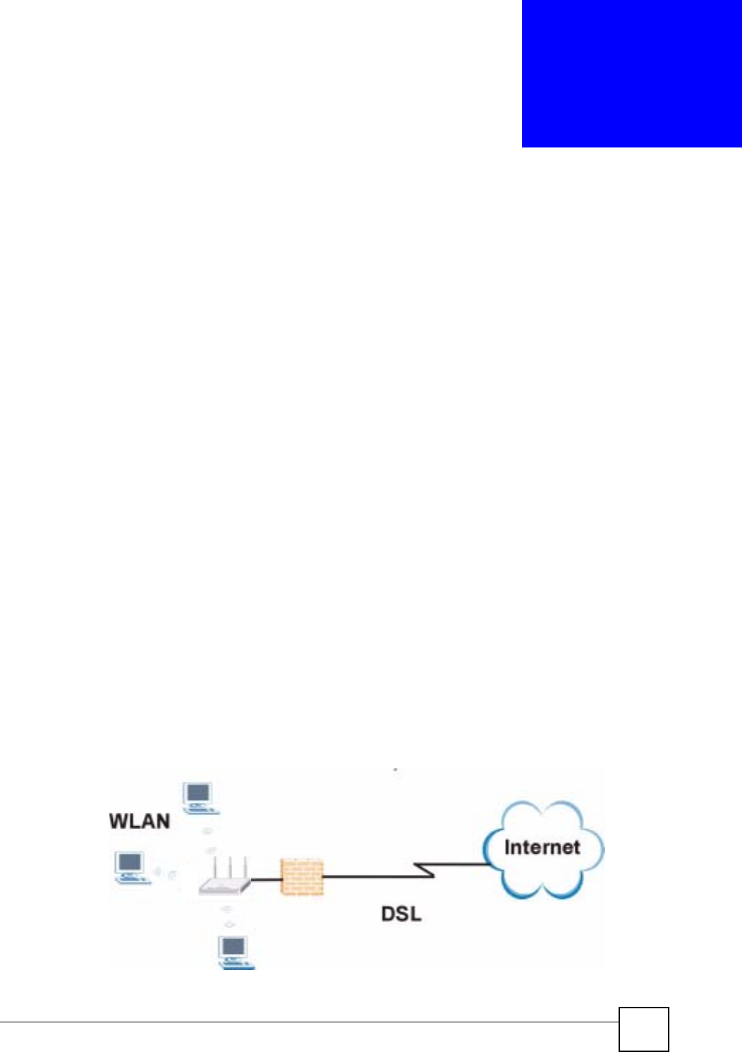
NBG-460N User’s Guide 31
CHAPTER 1
Getting to Know Your NBG-460N
This chapter introduces the main features and applications of the NBG-460N.
1.1 Overview
The NBG-460N acts as either an access point (AP) or a secure broadband router for all data
passing between the Internet and your local network. In both AP and Router Mode you can
set up a wireless network with other IEEE 802.11b/g/n compatible devices. In Router Mode a
number of services such as a firewall, IPSec VPN and content filtering are also available. You
can use media bandwidth management to efficiently manage traffic on your network.
Bandwidth management features allow you to prioritize time-sensitive or highly important
applications such as Voice over the Internet (VoIP).
The NBG-460N also uses MIMO (Multiple-Input, Multiple-Output) antenna technology and
Gigabit Ethernet ports to deliver high-speed wireless networking.
1.2 Router Mode
Select Router Mode if you need to route traffic between your network and another network
such as the Internet, and require important network services such as a firewall or bandwidth
management.
The following figure shows computers in a WLAN connecting to the NBG-460N (A), which
has a DSL connection to the Internet. The NBG-460N is set to Router Mode and has router
features such as a built-in firewall (B).
Figure 1 Secure Wireless Internet Access in Router Mode
AB
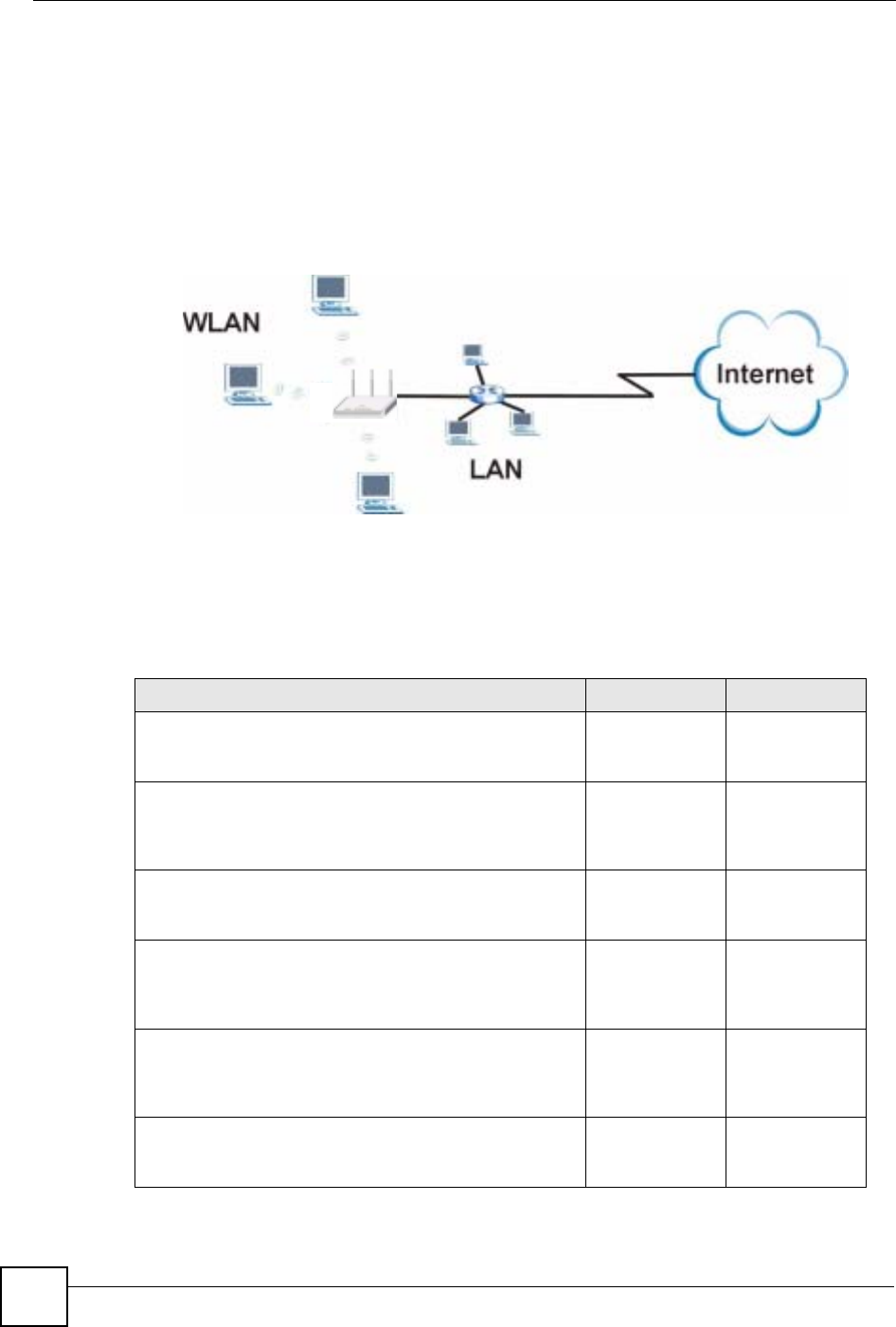
Chapter 1 Getting to Know Your NBG-460N
NBG-460N User’s Guide
32
1.3 AP Mode
Select AP Mode if you already have a router or gateway on your network which provides
network services such as a firewall or bandwidth management.
The following figure shows computers in a WLAN connecting to the NBG-460N, which acts
as an access point (A). The NBG-460N allows the wireless computers to share the same
Internet access as the other computers connected to the router (B) on the same network.
Figure 2 Wireless Internet Access in AP Mode
1.4 Router Features vs. AP Features
The following table shows which features are available in Router or AP Mode.
AB
Table 1 Features Available in Router Mode vs. AP Mode
FEATURE ROUTER MODE AP MODE
DHCP
This allows individual clients to obtain IP addresses at start-
up from a DHCP server.
YES NO
Firewall
This establishes a network security barrier, protecting your
network from attacks and controlling access between your
network and the Internet.
YES NO
Bandwidth Management
This allows you to allocate network bandwidth to specific
applications and or subnets.
YES NO
Any IP
This allows a computer to access the NBG-460N when the
IP addresses of the computer and the NBG-460N are not in
the same subnet.)
YES NO
VPN
A virtual private network (VPN) provides secure
communications between sites without the expense of
leased site-to-site lines.
YES NO
Wireless
This allows two or more devices to communicate without
wires, based on IEEE 802.11 wireless standards.
YES YES
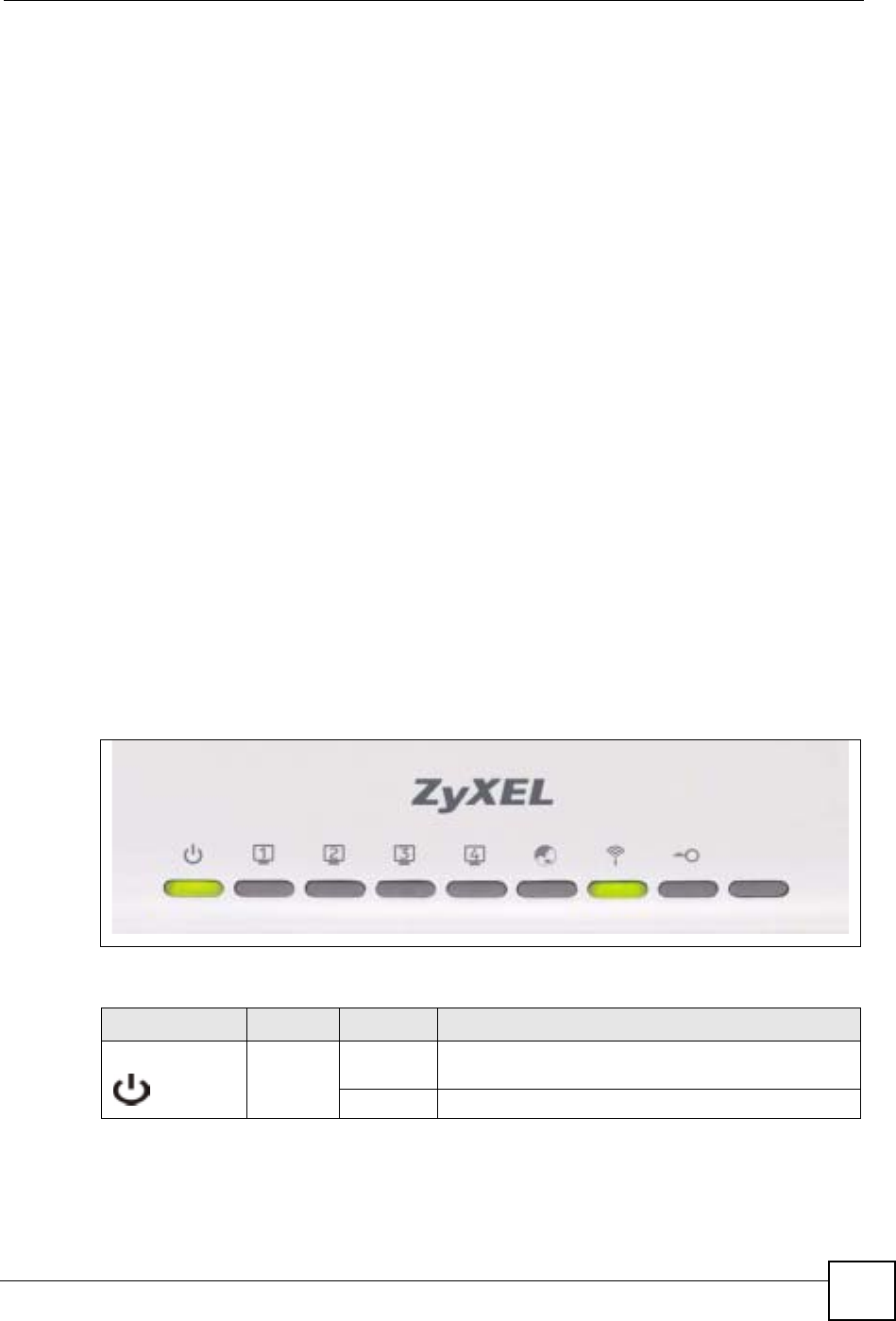
Chapter 1 Getting to Know Your NBG-460N
NBG-460N User’s Guide 33
1.5 Ways to Manage the NBG-460N
Use any of the following methods to manage the NBG-460N.
• Web Configurator. This is recommended for everyday management of the NBG-460N
using a (supported) web browser.
• Command Line Interface. Line commands are mostly used for troubleshooting by service
engineers.
• FTP. Use File Transfer Protocol for firmware upgrades and configuration backup/restore.
1.6 Good Habits for Managing the NBG-460N
Do the following things regularly to make the NBG-460N more secure and to manage the
NBG-460N more effectively.
• Change the password. Use a password that’s not easy to guess and that consists of
different types of characters, such as numbers and letters.
• Write down the password and put it in a safe place.
• Back up the configuration (and make sure you know how to restore it). Restoring an
earlier working configuration may be useful if the device becomes unstable or even
crashes. If you forget your password, you will have to reset the NBG-460N to its factory
default settings. If you backed up an earlier configuration file, you would not have to
totally re-configure the NBG-460N. You could simply restore your last configuration.
1.7 LEDs
Figure 3 Front Panel
The following table describes the LEDs.
Table 2 Front Panel LEDs
LED COLOR STATUS DESCRIPTION
POWER Green On The NBG-460N is receiving power and functioning
properly.
Off The NBG-460N is not receiving power.
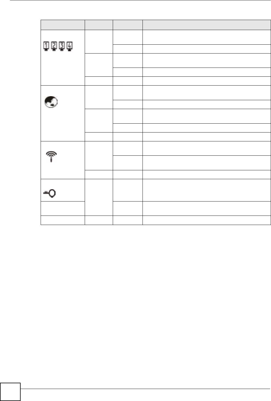
Chapter 1 Getting to Know Your NBG-460N
NBG-460N User’s Guide
34
LAN 1-4 Green On The NBG-460N has a successful 10/100MB Ethernet
connection.
Blinking The NBG-460N is sending/receiving data.
Amber On The NBG-460N has a successful 1000MB Ethernet
connection.
Blinking The NBG-460N is sending/receiving data.
Off The LAN is not connected.
WAN Green On The NBG-460N has a successful 10/100MB WAN
connection.
Blinking The NBG-460N is sending/receiving data.
Amber On The NBG-460N has a successful 1000MB Ethernet
connection.
Blinking The NBG-460N is sending/receiving data.
Off The WAN connection is not ready, or has failed.
WLAN Green On The NBG-460N is ready, but is not sending/receiving
data through the wireless LAN.
Blinking The NBG-460N is sending/receiving data through the
wireless LAN.
Off The wireless LAN is not ready or has failed.
WPS Green On WPS (WiFi Protected Setup) is configured on your
device.
Blinking The NBG-460N is attempting to connect with another
wireless devices using WPS.
Off WPS is disabled on your device.
Table 2 Front Panel LEDs (continued)
LED COLOR STATUS DESCRIPTION

NBG-460N User’s Guide 35
CHAPTER 2
The WPS Button
2.1 Overview
Your NBG-460N supports WiFi Protected Setup (WPS), which is an easy way to set up a
secure wireless network. WPS is an industry standard specification, defined by the WiFi
Alliance.
WPS allows you to quickly set up a wireless network with strong security, without having to
configure security settings manually. Each WPS connection works between two devices. Both
devices must support WPS (check each device’s documentation to make sure).
Depending on the devices you have, you can either press a button (on the device itself, or in its
configuration utility) or enter a PIN (a unique Personal Identification Number that allows one
device to authenticate the other) in each of the two devices. When WPS is activated on a
device, it has two minutes to find another device that also has WPS activated. Then, the two
devices connect and set up a secure network by themselves.
For more information on using WPS, see Section 6.1.2 on page 73.

Chapter 2 The WPS Button
NBG-460N User’s Guide
36

NBG-460N User’s Guide 37
CHAPTER 3
Introducing the Web
Configurator
This chapter describes how to access the NBG-460N web configurator and provides an
overview of its screens.
3.1 Web Configurator Overview
The web configurator is an HTML-based management interface that allows easy setup and
management of the NBG-460N via Internet browser. Use Internet Explorer 6.0 and later or
Netscape Navigator 7.0 and later versions or Safari 2.0 or later versions. The recommended
screen resolution is 1024 by 768 pixels.
In order to use the web configurator you need to allow:
• Web browser pop-up windows from your device. Web pop-up blocking is enabled by
default in Windows XP SP (Service Pack) 2.
• JavaScripts (enabled by default).
• Java permissions (enabled by default).
Refer to the Troubleshooting chapter to see how to make sure these functions are allowed in
Internet Explorer.
3.2 Accessing the Web Configurator
1Make sure your NBG-460N hardware is properly connected and prepare your computer
or computer network to connect to the NBG-460N (refer to the Quick Start Guide).
2Launch your web browser.
3Type "http://192.168.1.1" as the website address.
Your computer must be in the same subnet in order to access this website address.
•In Router Mode enable the DHCP Server. The NBG-460N assigns your computer an IP
address on the same subnet.
•In AP Mode the NBG-460N does not assign an IP address to your computer, so you
should check it’s in the same subnet. See Section 5.5 on page 71 for more information.
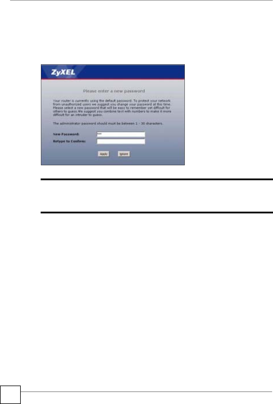
Chapter 3 Introducing the Web Configurator
NBG-460N User’s Guide
38
4Type "1234" (default) as the password and click Login. In some versions, the default
password appears automatically - if this is the case, click Login.
5You should see a screen asking you to change your password (highly recommended) as
shown next. Type a new password (and retype it to confirm) and click Apply or click
Ignore.
Figure 4 Change Password Screen
"The management session automatically times out when the time period set in
the Administrator Inactivity Timer field expires (default five minutes). Simply
log back into the NBG-460N if this happens.
6Select the setup mode you want to use.
• Click Go to Wizard Setup to use the Configuration Wizard for basic Internet and
Wireless setup.
• Click Go to Basic Setup if you want to view and configure basic settings that are not
part of the wizard setup. Not all Web Configurator screens are available in this mode.
See Chapter 23 on page 257 for more information.
•Click Go to Advanced Setup to view and configure all the NBG-460N’s settings.
• Select a language to go to the basic web configurator in that language. To change to
the advanced configurator see Chapter 23 on page 257.
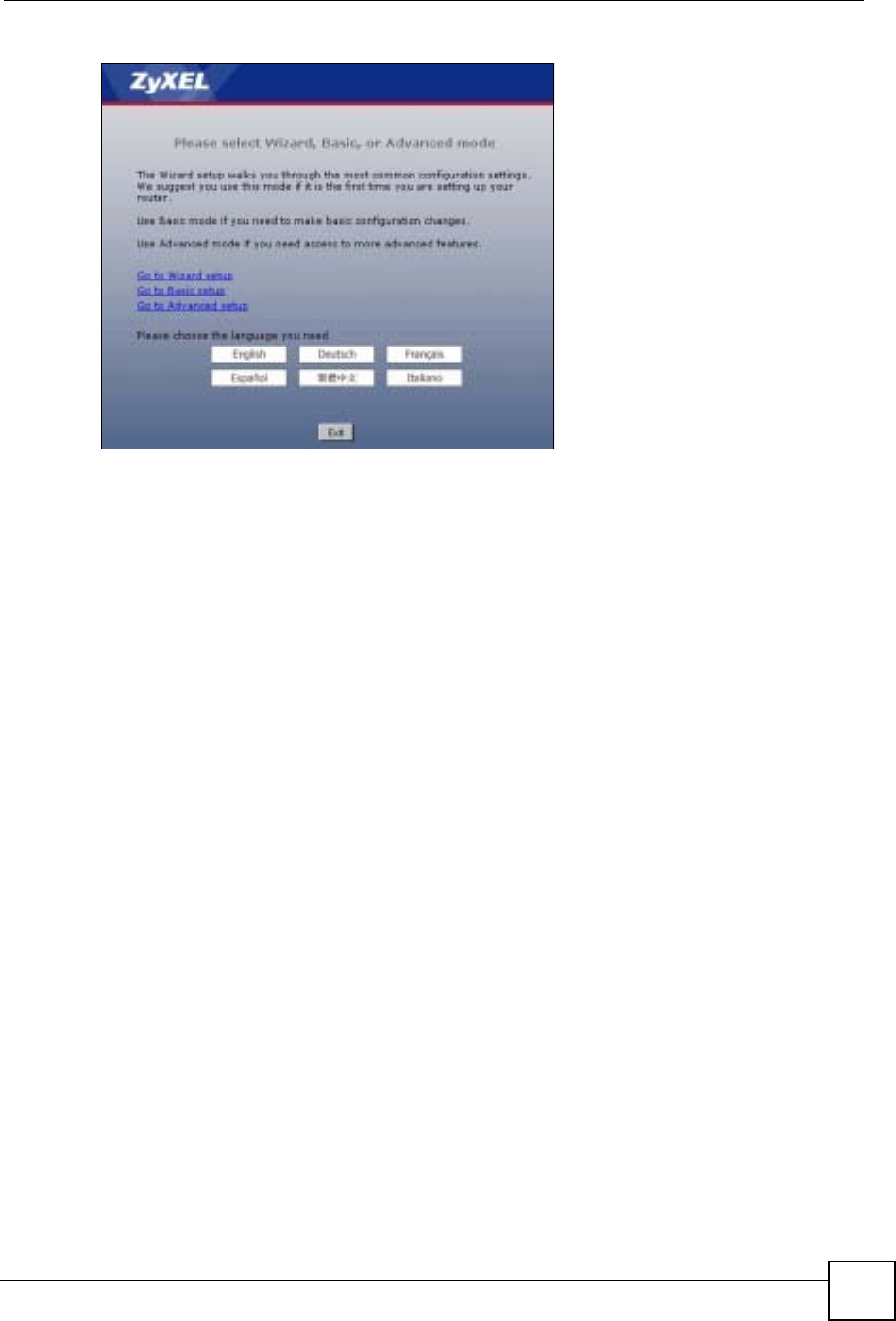
Chapter 3 Introducing the Web Configurator
NBG-460N User’s Guide 39
Figure 5 Selecting the setup mode
3.3 Resetting the NBG-460N
If you forget your password or IP address, or you cannot access the web configurator, you will
need to use the RESET button at the back of the NBG-460N to reload the factory-default
configuration file. This means that you will lose all configurations that you had previously
saved, the password will be reset to “1234” and the IP address will be reset to “192.168.1.1”.
3.3.1 Procedure to Use the Reset Button
1Make sure the power LED is on.
2Press the RESET button for five seconds or until the power LED begins to blink and
then release it. When the power LED begins to blink, the defaults have been restored and
the NBG-460N restarts.
3.4 Navigating the Web Configurator
The following summarizes how to navigate the web configurator from the Status screen in
Router Mode and AP Mode.
3.5 The Status Screen in Router Mode
Click on Status. The screen below shows the status screen in Router Mode.
(For information on the status screen in AP Mode see Chapter 5 on page 66.)
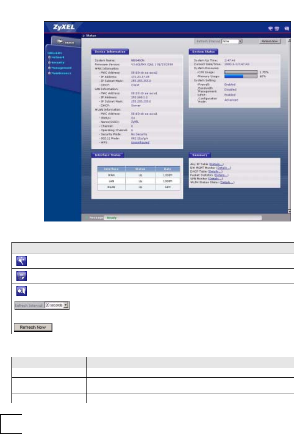
Chapter 3 Introducing the Web Configurator
NBG-460N User’s Guide
40
Figure 6 Web Configurator Status Screen
The following table describes the icons shown in the Status screen.
The following table describes the labels shown in the Status screen.
Table 3 Status Screen Icon Key
ICON DESCRIPTION
Click this icon to open the setup wizard.
Click this icon to view copyright and a link for related product information.
Click this icon at any time to exit the web configurator.
Select a number of seconds or None from the drop-down list box to refresh all screen
statistics automatically at the end of every time interval or to not refresh the screen
statistics.
Click this button to refresh the status screen statistics.
Table 4 Web Configurator Status Screen
LABEL DESCRIPTION
Device Information
System Name This is the System Name you enter in the Maintenance > System > General
screen. It is for identification purposes.
Firmware Version This is the firmware version and the date created.

Chapter 3 Introducing the Web Configurator
NBG-460N User’s Guide 41
WAN Information
- MAC Address This shows the WAN Ethernet adapter MAC Address of your device.
- IP Address This shows the WAN port’s IP address.
- IP Subnet Mask This shows the WAN port’s subnet mask.
- DHCP This shows the WAN port’s DHCP role - Client or None.
LAN Information
- MAC Address This shows the LAN Ethernet adapter MAC Address of your device.
- IP Address This shows the LAN port’s IP address.
- IP Subnet Mask This shows the LAN port’s subnet mask.
- DHCP This shows the LAN port’s DHCP role - Server or None.
WLAN Information
- MAC Address This shows the wireless adapter MAC Address of your device.
- Status This shows the current status of the Wireless LAN - On,Off or Off by scheduler.
- Name (SSID) This shows a descriptive name used to identify the NBG-460N in the wireless LAN.
- Channel This shows the channel number which you select manually.
- Operating Channel This shows the channel number which the NBG-460N is currently using over the
wireless LAN.
- Security Mode This shows the level of wireless security the NBG-460N is using.
- 802.11 Mode This shows the wireless standard.
- WPS This displays Configured when the WPS has been set up.
This displays Unconfigured if the WPS has not been set up.
Click the status to display Network > Wireless LAN > WPS screen.
System Status
System Up Time This is the total time the NBG-460N has been on.
Current Date/Time This field displays your NBG-460N’s present date and time.
System Resource
- CPU Usage This displays what percentage of the NBG-460N’s processing ability is currently
used. When this percentage is close to 100%, the NBG-460N is running at full load,
and the throughput is not going to improve anymore. If you want some applications to
have more throughput, you should turn off other applications (for example, using
bandwidth management.
- Memory Usage This shows what percentage of the heap memory the NBG-460N is using. Heap
memory refers to the memory that is not used by ZyNOS (ZyXEL Network Operating
System) and is thus available for running processes like NAT and the firewall.
System Setting
- Firewall This shows whether the firewall is active or not.
- Bandwidth Management This shows whether the bandwidth management is active or not.
- UPnP This shows whether UPnP is active or not.
- Configuration Mode This shows whether the advanced screens of each feature are turned on
(Advanced) or not (Basic).
Interface Status
Interface This displays the NBG-460N port types. The port types are: WAN,LAN and WLAN.
Table 4 Web Configurator Status Screen (continued)
LABEL DESCRIPTION

Chapter 3 Introducing the Web Configurator
NBG-460N User’s Guide
42
3.5.1 Navigation Panel
Use the sub-menus on the navigation panel to configure NBG-460N features.
The following table describes the sub-menus.
Status For the LAN and WAN ports, this field displays Down (line is down) or Up (line is up
or connected).
For the WLAN, it displays Up when the WLAN is enabled or Down when the WLAN
is disabled.
Rate For the LAN ports, this displays the port speed and duplex setting or N/A when the
line is disconnected.
For the WAN port, it displays the port speed and duplex setting if you’re using
Ethernet encapsulation and Idle (line (ppp) idle), Dial (starting to trigger a call) and
Drop (dropping a call) if you're using PPPoE or PPTP encapsulation. This field
displays N/A when the line is disconnected.
For the WLAN, it displays the maximum transmission rate when the WLAN is
enabled and N/A when the WLAN is disabled.
Summary
Any IP Table Use this screen to view details of IP addresses assigned to devices not in the same
subnet as the NBG-460N.
BW MGMT Monitor Use this screen to view the NBG-460N’s bandwidth usage and allotments.
DHCP Table Use this screen to view current DHCP client information.
Packet Statistics Use this screen to view port status and packet specific statistics.
VPN Monitor Use this screen to view the active VPN connections.
WLAN Station Status Use this screen to view the wireless stations that are currently associated to the
NBG-460N.
Table 4 Web Configurator Status Screen (continued)
LABEL DESCRIPTION
Table 5 Screens Summary
LINK TAB FUNCTION
Status This screen shows the NBG-460N’s general device, system and
interface status information. Use this screen to access the wizard,
and summary statistics tables.
Network
Wireless
LAN General Use this screen to configure wireless LAN.
MAC Filter Use the MAC filter screen to configure the NBG-460N to block
access to devices or block the devices from accessing the NBG-
460N.
Advanced This screen allows you to configure advanced wireless settings.
QoS Use this screen to configure Wi-Fi Multimedia Quality of Service
(WMM QoS). WMM QoS allows you to prioritize wireless traffic
according to the delivery requirements of individual services.
WPS Use this screen to configure WPS.
WPS Station Use this screen to add a wireless station using WPS.
Scheduling Use this screen to schedule the times the Wireless LAN is enabled.
WAN Internet
Connection This screen allows you to configure ISP parameters, WAN IP
address assignment, DNS servers and the WAN MAC address.
Advanced Use this screen to configure other advanced properties.

Chapter 3 Introducing the Web Configurator
NBG-460N User’s Guide 43
LAN IP Use this screen to configure LAN IP address and subnet mask.
IP Alias Use this screen to partition your LAN interface into subnets.
Advanced Use this screen to enable other advanced properties.
DHCP
Server General Use this screen to enable the NBG-460N’s DHCP server.
Advanced Use this screen to assign IP addresses to specific individual
computers based on their MAC addresses and to have DNS
servers assigned by the DHCP server.
Client List Use this screen to view current DHCP client information and to
always assign an IP address to a MAC address (and host name).
NAT General Use this screen to enable NAT.
Application Use this screen to configure servers behind the NBG-460N.
Advanced Use this screen to change your NBG-460N’s port triggering
settings.
DDNS General Use this screen to set up dynamic DNS.
Security
Firewall General Use this screen to activate/deactivate the firewall.
Services This screen shows a summary of the firewall rules, and allows you
to edit/add a firewall rule.
Content Filter Filter Use this screen to block certain web features and sites containing
certain keywords in the URL.
Schedule Use this screen to set the days and times for the NBG-460N to
perform content filtering.
VPN General Use this screen to configure VPN connections and view the rule
summary.
SA Monitor Use this screen to display and manage active VPN connections.
Management
Static Route IP Static
Route Use this screen to configure IP static routes.
Bandwidth
MGMT General Use this screen to enable bandwidth management.
Advanced Use this screen to set the upstream bandwidth and edit a
bandwidth management rule.
Monitor Use this screen to view the NBG-460N’s bandwidth usage and
allotments.
Remote
MGMT WWW Use this screen to configure through which interface(s) and from
which IP address(es) users can use HTTP to manage the NBG-
460N.
Telnet Use this screen to configure through which interface(s) and from
which IP address(es) users can use Telnet to manage the NBG-
460N.
FTP Use this screen to configure through which interface(s) and from
which IP address(es) users can use FTP to access the NBG-460N.
DNS Use this screen to configure through which interface(s) and from
which IP address(es) users can send DNS queries to the NBG-
460N.
UPnP General Use this screen to enable UPnP on the NBG-460N.
Table 5 Screens Summary
LINK TAB FUNCTION
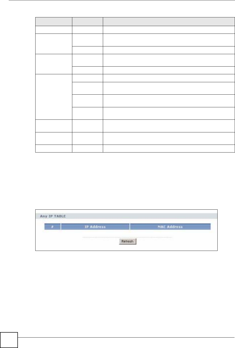
Chapter 3 Introducing the Web Configurator
NBG-460N User’s Guide
44
3.5.2 Summary: Any IP Table
This screen displays the IP address of each computer that is using the NBG-460N via the any
IP feature. Any IP allows computers to access the Internet through the NBG-460N without
changing their network settings when NAT is enabled. To access this screen, open the Status
screen (see Section 3.5 on page 39), and click (Details...) next to Any IP Table.
Figure 7 Any IP Table
3.5.3 Summary: Bandwidth Management Monitor
Select the BW MGMT Monitor (Details...) hyperlink in Status screen. View the bandwidth
usage of the WAN configured bandwidth rules. This is also shown as bandwidth usage over
the bandwidth budget for each rule. The gray section of the bar represents the percentage of
unused bandwidth and the blue color represents the percentage of bandwidth in use.
Maintenance
System General Use this screen to view and change administrative settings such as
system and domain names, password and inactivity timer.
Time Setting Use this screen to change your NBG-460N’s time and date.
Logs View Log Use this screen to view the logs for the categories that you
selected.
Log Settings Use this screen to change your NBG-460N’s log settings.
Tools Firmware Use this screen to upload firmware to your NBG-460N.
Configuration Use this screen to backup and restore the configuration or reset
the factory defaults to your NBG-460N.
Restart This screen allows you to reboot the NBG-460N without turning the
power off.
Wake On
LAN Use this screen to remotely turn on a device on the network.
Config Mode General This screen allows you to display or hide the advanced screens or
features.
Sys OP
Mode General This screen allows you to select whether your device acts as a
Router or a Access Point.
Language This screen allows you to select the language you prefer.
Table 5 Screens Summary
LINK TAB FUNCTION
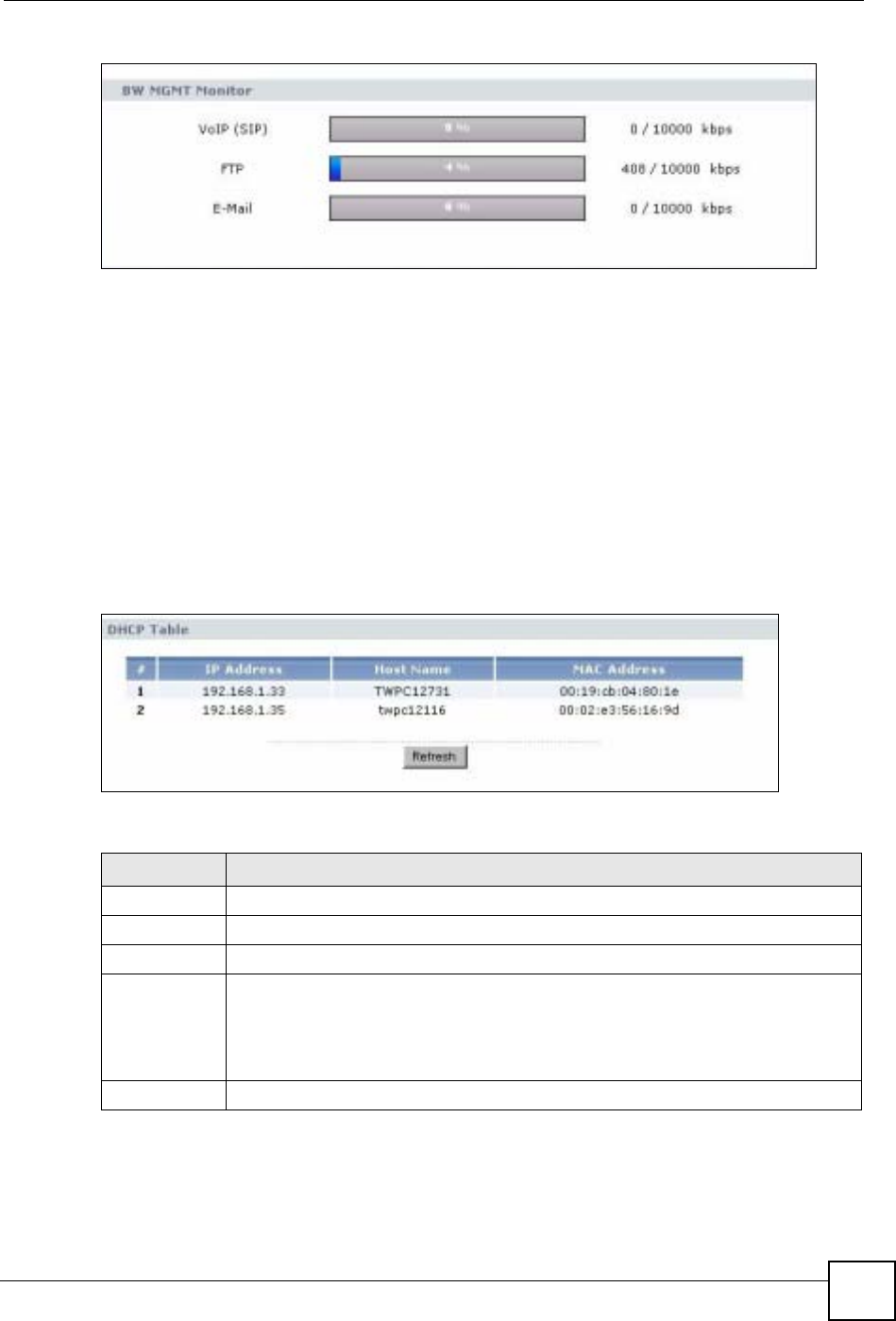
Chapter 3 Introducing the Web Configurator
NBG-460N User’s Guide 45
Figure 8 Summary: BW MGMT Monitor
3.5.4 Summary: DHCP Table
DHCP (Dynamic Host Configuration Protocol, RFC 2131 and RFC 2132) allows individual
clients to obtain TCP/IP configuration at start-up from a server. You can configure the NBG-
460N’s LAN as a DHCP server or disable it. When configured as a server, the NBG-460N
provides the TCP/IP configuration for the clients. If DHCP service is disabled, you must have
another DHCP server on that network, or else the computer must be manually configured.
Click the DHCP Table (Details...) hyperlink in the Status screen. Read-only information here
relates to your DHCP status. The DHCP table shows current DHCP client information
(including IP Address,Host Name and MAC Address) of all network clients using the
NBG-460N’s DHCP server.
Figure 9 Summary: DHCP Table
The following table describes the labels in this screen.
Table 6 Summary: DHCP Table
LABEL DESCRIPTION
# This is the index number of the host computer.
IP Address This field displays the IP address relative to the # field listed above.
Host Name This field displays the computer host name.
MAC Address This field shows the MAC address of the computer with the name in the Host Name
field.
Every Ethernet device has a unique MAC (Media Access Control) address which
uniquely identifies a device. The MAC address is assigned at the factory and consists
of six pairs of hexadecimal characters, for example, 00:A0:C5:00:00:02.
Refresh Click Refresh to renew the screen.
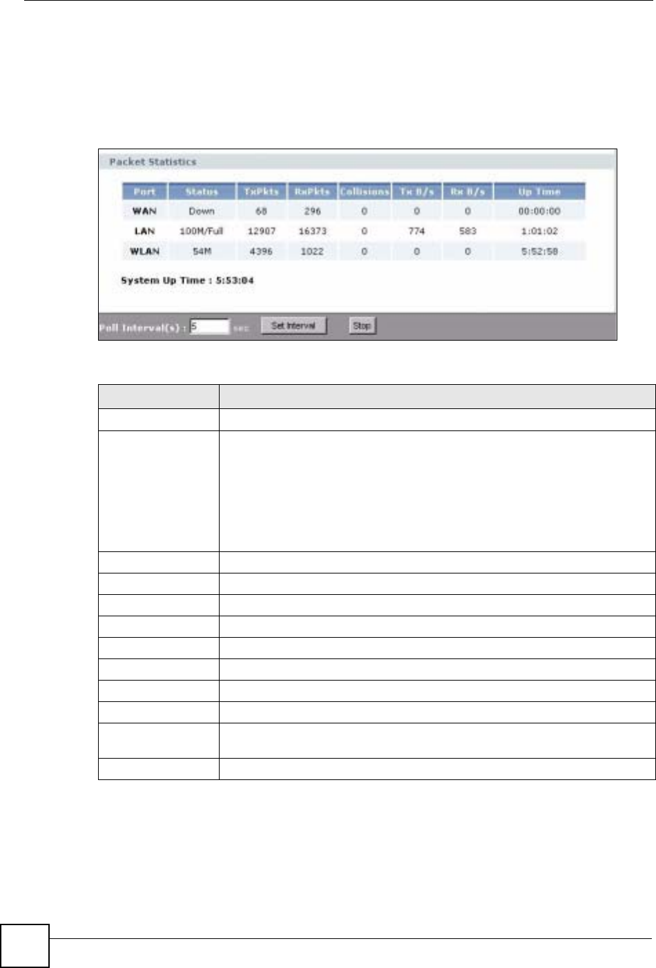
Chapter 3 Introducing the Web Configurator
NBG-460N User’s Guide
46
3.5.5 Summary: Packet Statistics
Click the Packet Statistics (Details...) hyperlink in the Status screen. Read-only information
here includes port status, packet specific statistics and the "system up time". The Poll
Interval(s) field is configurable and is used for refreshing the screen.
Figure 10 Summary: Packet Statistics
The following table describes the labels in this screen.
Table 7 Summary: Packet Statistics
LABEL DESCRIPTION
Port This is the NBG-460N’s port type.
Status For the LAN ports, this displays the port speed and duplex setting or Down
when the line is disconnected.
For the WAN port, it displays the port speed and duplex setting if you’re using
Ethernet encapsulation and Idle (line (ppp) idle), Dial (starting to trigger a call)
and Drop (dropping a call) if you're using PPPoE or PPTP encapsulation. This
field displays Down when the line is disconnected.
For the WLAN, it displays the maximum transmission rate when the WLAN is
enabled and Down when the WLAN is disabled.
TxPkts This is the number of transmitted packets on this port.
RxPkts This is the number of received packets on this port.
Collisions This is the number of collisions on this port.
Tx B/s This displays the transmission speed in bytes per second on this port.
Rx B/s This displays the reception speed in bytes per second on this port.
Up Time This is the total amount of time the line has been up.
System Up Time This is the total time the NBG-460N has been on.
Poll Interval(s) Enter the time interval for refreshing statistics in this field.
Set Interval Click this button to apply the new poll interval you entered in the Poll Interval(s)
field.
Stop Click Stop to stop refreshing statistics.
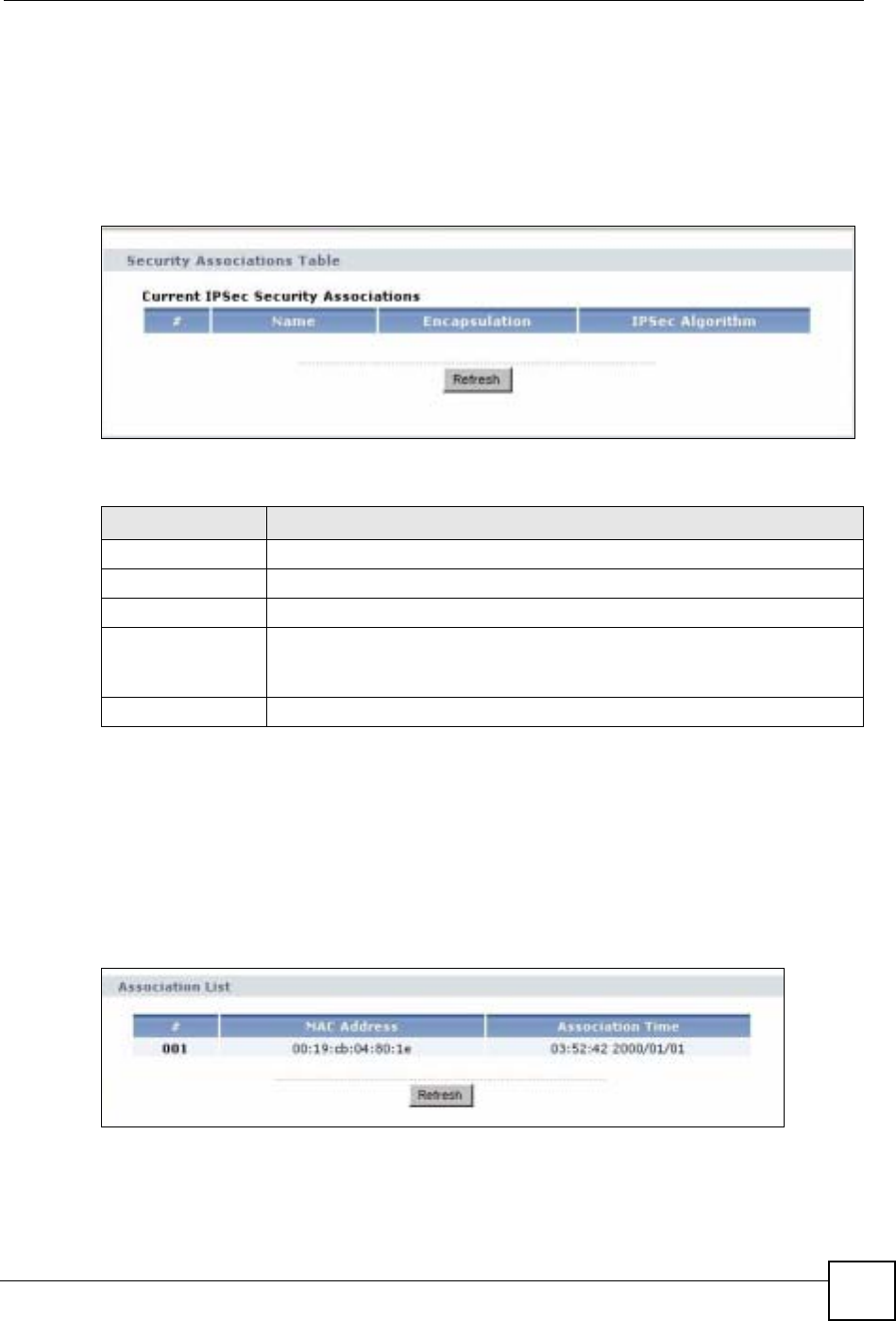
Chapter 3 Introducing the Web Configurator
NBG-460N User’s Guide 47
3.5.6 Summary: VPN Monitor
Click the VPN Monitor (Details...) hyperlink in the Status screen. This screen displays read-
only information about the active VPN connections. Click the Refresh button to update the
screen. A Security Association (SA) is the group of security settings related to a specific VPN
tunnel.
Figure 11 Summary: VPN Monitor
The following table describes the labels in this screen.
3.5.7 Summary: Wireless Station Status
Click the WLAN Station Status (Details...) hyperlink in the Status screen. View the wireless
stations that are currently associated to the NBG-460N in the Association List. Association
means that a wireless client (for example, your network or computer with a wireless network
card) has connected successfully to the AP (or wireless router) using the same SSID, channel
and security settings.
Figure 12 Summary: Wireless Association List
Table 8 Summary: Wireless Association List
LABEL DESCRIPTION
# This is the security association index number.
Name This field displays the identification name for this VPN tunnel.
Encapsulation This field displays Tunnel or Transport mode.
IPSec Algorithm This field displays the security protocols used for an SA.
Both AH and ESP increase NBG-460N processing requirements and
communications latency (delay).
Refresh Click this button to update the screen’s statistics immediately.

Chapter 3 Introducing the Web Configurator
NBG-460N User’s Guide
48
The following table describes the labels in this screen.
Table 9 Summary: Wireless Association List
LABEL DESCRIPTION
#This is the index number of an associated wireless station.
MAC Address This field displays the MAC address of an associated wireless station.
Association Time This field displays the time a wireless station first associated with the NBG-
460N’s WLAN network.
Refresh Click Refresh to reload the list.
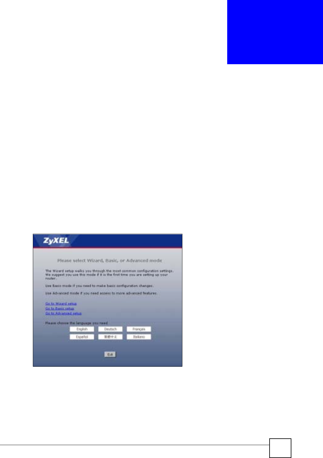
NBG-460N User’s Guide 49
CHAPTER 4
Connection Wizard
This chapter provides information on the wizard setup screens in the web configurator.
4.1 Wizard Setup
The web configurator’s wizard setup helps you configure your device to access the Internet.
Refer to your ISP (Internet Service Provider) checklist in the Quick Start Guide to know what
to enter in each field. Leave a field blank if you don’t have that information.
1After you access the NBG-460N web configurator, click the Go to Wizard setup
hyperlink.
You can click the Go to Basic setup or Go to Advanced setup hyperlink to skip this
wizard setup and configure basic or advanced features accordingly.
Figure 13 Select Wizard or Advanced Mode
2Choose a language by clicking on the language’s button. The screen will update. Click
the Next button to proceed to the next screen.
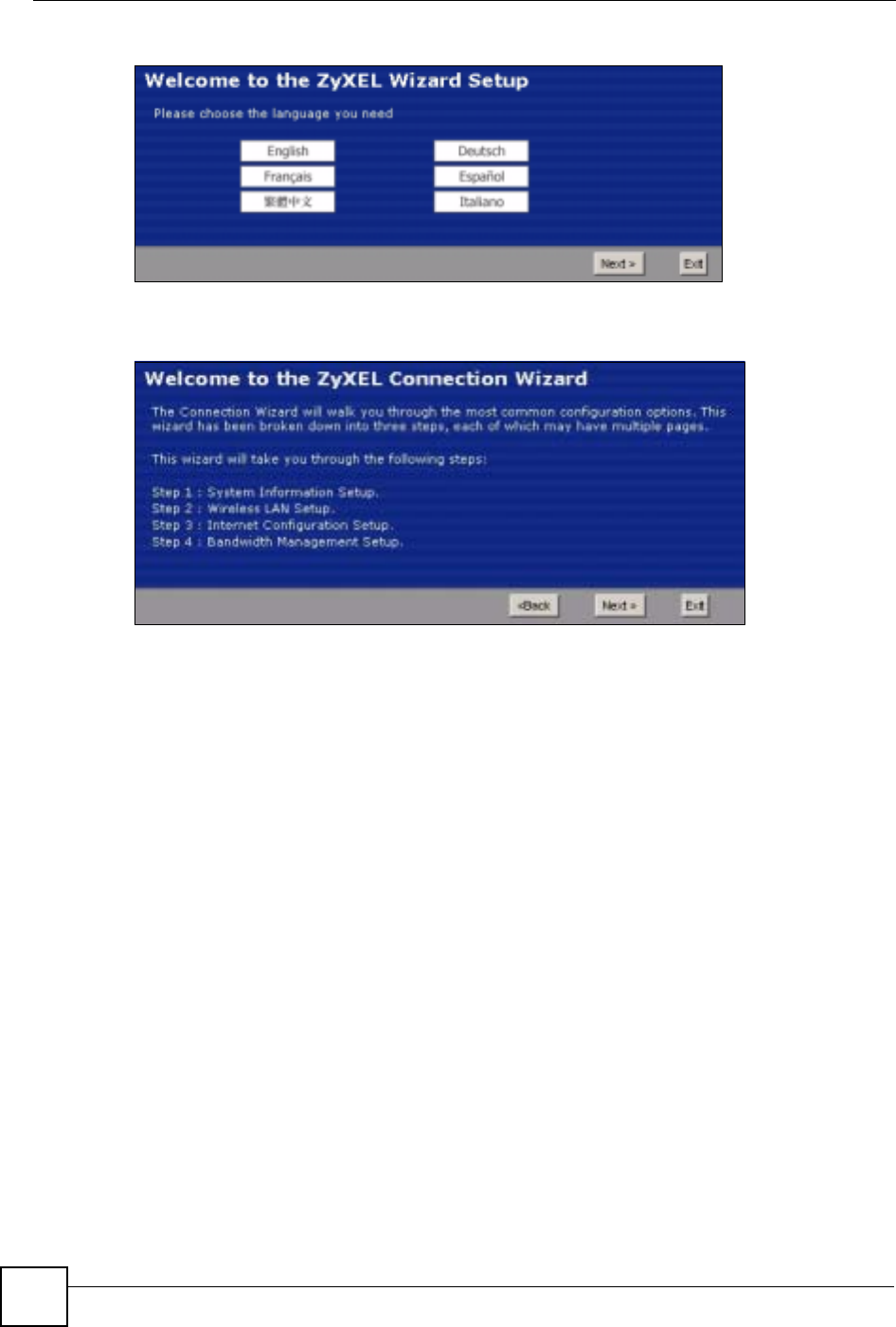
Chapter 4 Connection Wizard
NBG-460N User’s Guide
50
Figure 14 Select a Language
3Read the on-screen information and click Next.
Figure 15 Welcome to the Connection Wizard
4.2 Connection Wizard: STEP 1: System Information
System Information contains administrative and system-related information.
4.2.1 System Name
System Name is for identification purposes. However, because some ISPs check this name
you should enter your computer's "Computer Name".
• In Windows 95/98 click Start, Settings, Control Panel, Network. Click the
Identification tab, note the entry for the Computer Name field and enter it as the System
Name.
• In Windows 2000, click Start, Settings and Control Panel and then double-click System.
Click the Network Identification tab and then the Properties button. Note the entry for
the Computer name field and enter it as the System Name.
• In Windows XP, click Start, My Computer, View system information and then click
the Computer Name tab. Note the entry in the Full computer name field and enter it as
the NBG-460N System Name.
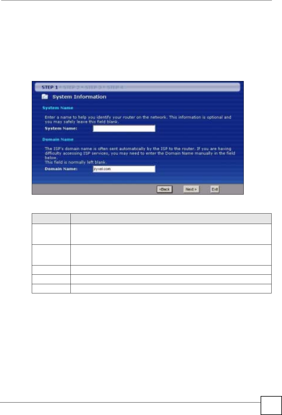
Chapter 4 Connection Wizard
NBG-460N User’s Guide 51
4.2.2 Domain Name
The Domain Name entry is what is propagated to the DHCP clients on the LAN. If you leave
this blank, the domain name obtained by DHCP from the ISP is used. While you must enter
the host name (System Name) on each individual computer, the domain name can be assigned
from the NBG-460N via DHCP.
Click Next to configure the NBG-460N for Internet access.
Figure 16 Wizard Step 1: System Information
The following table describes the labels in this screen.
4.3 Connection Wizard: STEP 2: Wireless LAN
Set up your wireless LAN using the following screen.
Table 10 Wizard Step 1: System Information
LABEL DESCRIPTION
System Name System Name is a unique name to identify the NBG-460N in an Ethernet network.
Enter a descriptive name. This name can be up to 30 alphanumeric characters long.
Spaces are not allowed, but dashes "-" and underscores "_" are accepted.
Domain Name Type the domain name (if you know it) here. If you leave this field blank, the ISP may
assign a domain name via DHCP. The domain name entered by you is given priority
over the ISP assigned domain name.
Back Click Back to display the previous screen.
Next Click Next to proceed to the next screen.
Exit Click Exit to close the wizard screen without saving.
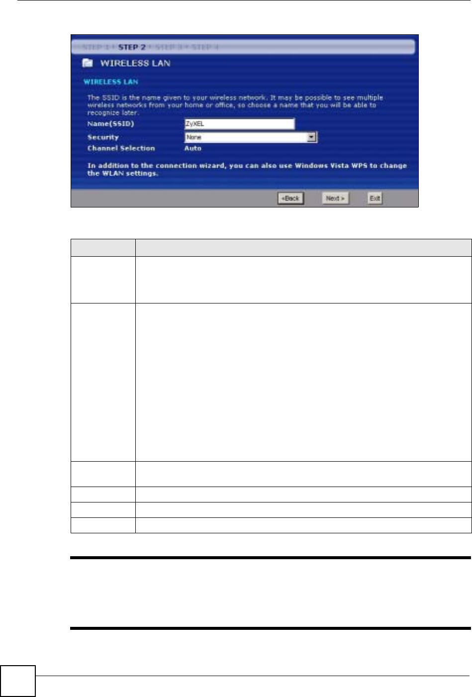
Chapter 4 Connection Wizard
NBG-460N User’s Guide
52
Figure 17 Wizard Step 2: Wireless LAN
The following table describes the labels in this screen.
"The wireless stations and NBG-460N must use the same SSID, channel ID
and WEP encryption key (if WEP is enabled), WPA-PSK (if WPA-PSK is
enabled) or WPA2-PSK (if WPA2-PSK is enabled) for wireless
communication.
Table 11 Wizard Step 2: Wireless LAN
LABEL DESCRIPTION
Name (SSID) Enter a descriptive name (up to 32 printable 7-bit ASCII characters) for the wireless
LAN.
If you change this field on the NBG-460N, make sure all wireless stations use the
same SSID in order to access the network.
Security Select a Security level from the drop-down list box.
Choose Auto (WPA2-PSK) to have the NBG-460N generate a pre-shared key
automatically. After you click Next a screen pops up displaying the generated pre-
shared key. Write down the key for use later when connecting other wireless devices
to your network. Click OK to continue.
Choose None to have no wireless LAN security configured. If you do not enable any
wireless security on your NBG-460N, your network is accessible to any wireless
networking device that is within range. If you choose this option, skip directly to
Section 4.4 on page 54.
Choose Basic (WEP) security if you want to configure WEP Encryption parameters. If
you choose this option, go directly to Section 4.3.1 on page 53. This option is only
available if WPS is not enabled.
Choose Extend (WPA-PSK or WPA2-PSK) security to configure a Pre-Shared Key.
Choose this option only if your wireless clients support WPA-PSK or WPA2-PSK
respectively. If you choose this option, skip directly to Section 4.3.2 on page 54.
Channel
Selection The range of radio frequencies used by IEEE 802.11b/g/n wireless devices is called a
channel. The device will automatically select the channel with the least interference.
Back Click Back to display the previous screen.
Next Click Next to proceed to the next screen.
Exit Click Exit to close the wizard screen without saving.
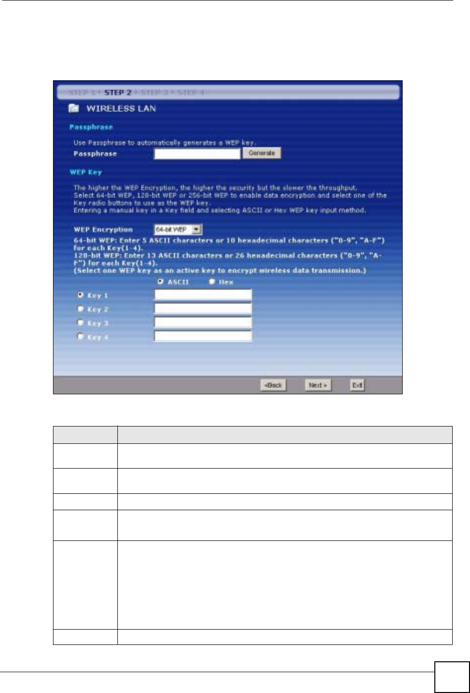
Chapter 4 Connection Wizard
NBG-460N User’s Guide 53
4.3.1 Basic (WEP) Security
Choose Basic (WEP) to setup WEP Encryption parameters.
Figure 18 Wizard Step 2: Basic (WEP) Security
The following table describes the labels in this screen.
Table 12 Wizard Step 2: Basic (WEP) Security
LABEL DESCRIPTION
Passphrase Type a Passphrase (up to 32 printable characters) and click Generate. The NBG-
460N automatically generates a WEP key.
WEP
Encryption Select 64-bit WEP or 128-bit WEP to allow data encryption.
ASCII Select this option in order to enter ASCII characters as the WEP keys.
HEX Select this option to enter hexadecimal characters as the WEP keys.
The preceding “0x” is entered automatically.
Key 1 to Key 4 The WEP keys are used to encrypt data. Both the NBG-460N and the wireless
stations must use the same WEP key for data transmission.
If you chose 64-bit WEP, then enter any 5 ASCII characters or 10 hexadecimal
characters ("0-9", "A-F").
If you chose 128-bit WEP, then enter 13 ASCII characters or 26 hexadecimal
characters ("0-9", "A-F").
You must configure at least one key, only one key can be activated at any one time.
The default key is key 1.
Back Click Back to display the previous screen.
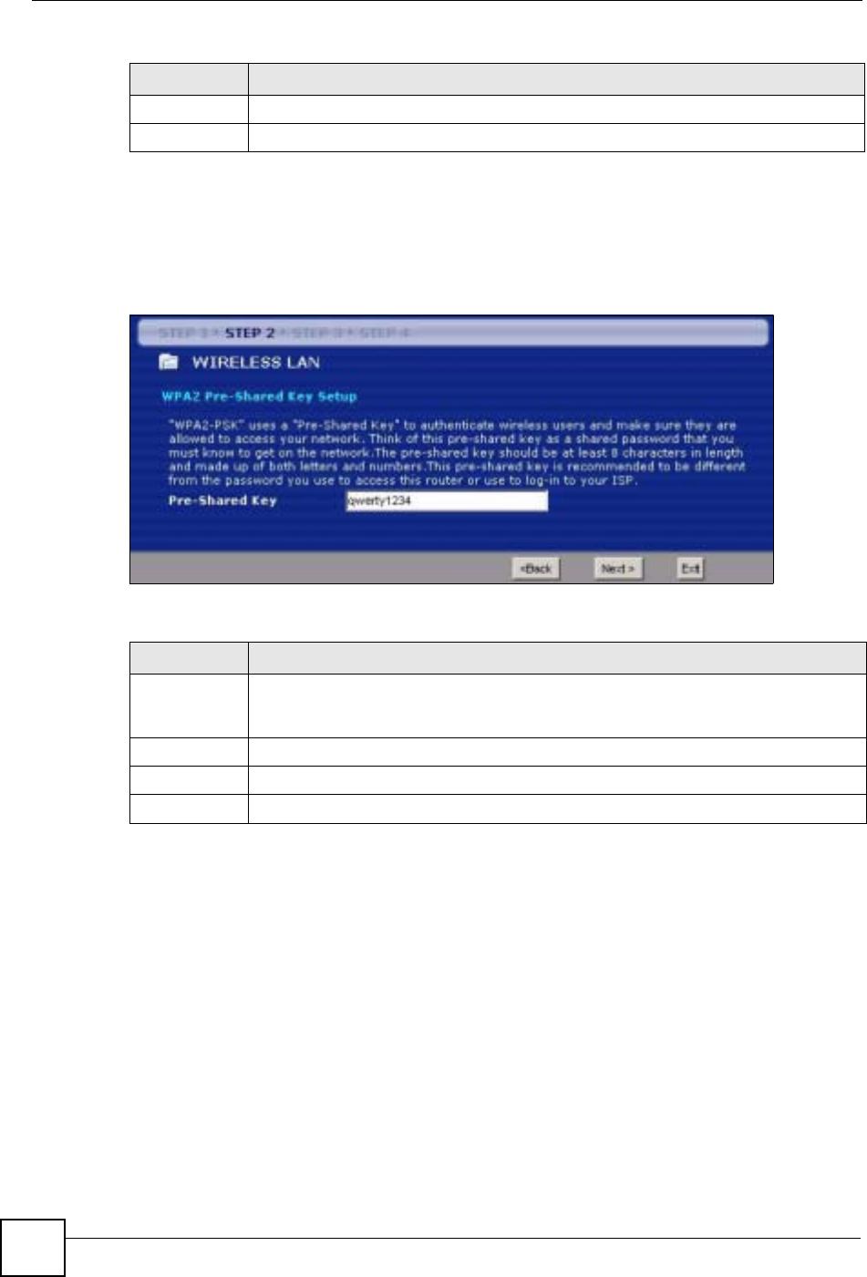
Chapter 4 Connection Wizard
NBG-460N User’s Guide
54
4.3.2 Extend (WPA-PSK or WPA2-PSK) Security
Choose Extend (WPA-PSK) or Extend (WPA2-PSK) security in the Wireless LAN setup
screen to set up a Pre-Shared Key.
Figure 19 Wizard Step 2: Extend (WPA-PSK or WPA2-PSK) Security
The following table describes the labels in this screen.
4.4 Connection Wizard: STEP 3: Internet Configuration
The NBG-460N offers three Internet connection types. They are Ethernet,PPP over
Ethernet or PPTP. The wizard attempts to detect which WAN connection type you are using.
If the wizard does not detect a connection type, you must select one from the drop-down list
box. Check with your ISP to make sure you use the correct type.
This wizard screen varies according to the connection type that you select.
Next Click Next to proceed to the next screen.
Exit Click Exit to close the wizard screen without saving.
Table 12 Wizard Step 2: Basic (WEP) Security
LABEL DESCRIPTION
Table 13 Wizard Step 2: Extend (WPA-PSK or WPA2-PSK) Security
LABEL DESCRIPTION
Pre-Shared
Key Type from 8 to 63 case-sensitive ASCII characters. You can set up the most secure
wireless connection by configuring WPA in the wireless LAN screens. You need to
configure an authentication server to do this.
Back Click Back to display the previous screen.
Next Click Next to proceed to the next screen.
Exit Click Exit to close the wizard screen without saving.
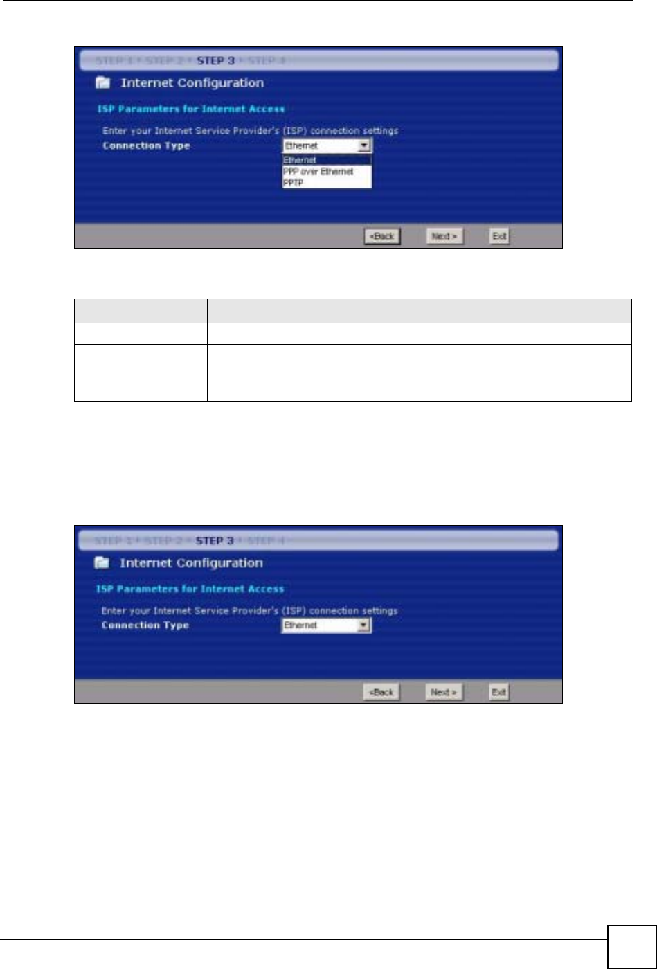
Chapter 4 Connection Wizard
NBG-460N User’s Guide 55
Figure 20 Wizard Step 3: ISP Parameters.
The following table describes the labels in this screen,
4.4.1 Ethernet Connection
Choose Ethernet when the WAN port is used as a regular Ethernet. Continue to Section 4.4.4
on page 58.
Figure 21 Wizard Step 3: Ethernet Connection
4.4.2 PPPoE Connection
Point-to-Point Protocol over Ethernet (PPPoE) functions as a dial-up connection. PPPoE is an
IETF (Internet Engineering Task Force) standard specifying how a host personal computer
interacts with a broadband modem (for example DSL, cable, wireless, etc.) to achieve access
to high-speed data networks.
For the service provider, PPPoE offers an access and authentication method that works with
existing access control systems (for instance, RADIUS).
Table 14 Wizard Step 3: ISP Parameters
CONNECTION TYPE DESCRIPTION
Ethernet Select the Ethernet option when the WAN port is used as a regular Ethernet.
PPPoE Select the PPP over Ethernet option for a dial-up connection. If your ISP
gave you an IP address and/or subnet mask, then select PPTP.
PPTP Select the PPTP option for a dial-up connection.
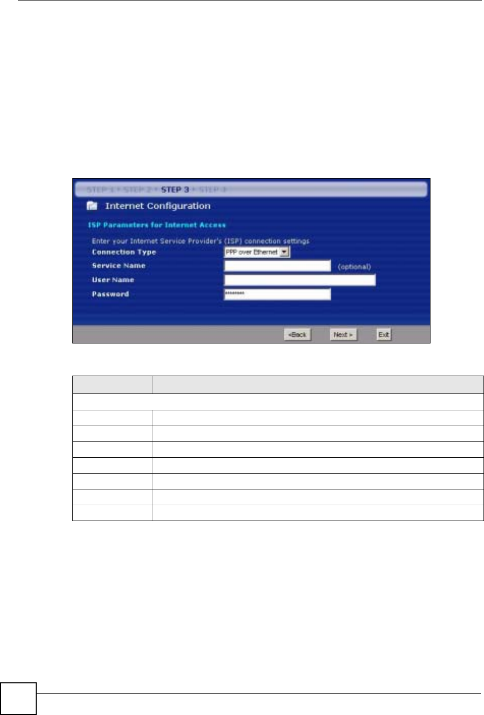
Chapter 4 Connection Wizard
NBG-460N User’s Guide
56
One of the benefits of PPPoE is the ability to let end users access one of multiple network
services, a function known as dynamic service selection. This enables the service provider to
easily create and offer new IP services for specific users.
Operationally, PPPoE saves significant effort for both the subscriber and the ISP/carrier, as it
requires no specific configuration of the broadband modem at the subscriber’s site.
By implementing PPPoE directly on the NBG-460N (rather than individual computers), the
computers on the LAN do not need PPPoE software installed, since the NBG-460N does that
part of the task. Furthermore, with NAT, all of the LAN's computers will have Internet access.
Refer to the appendix for more information on PPPoE.
Figure 22 Wizard Step 3: PPPoE Connection
The following table describes the labels in this screen.
4.4.3 PPTP Connection
Point-to-Point Tunneling Protocol (PPTP) is a network protocol that enables transfers of data
from a remote client to a private server, creating a Virtual Private Network (VPN) using TCP/
IP-based networks.
PPTP supports on-demand, multi-protocol, and virtual private networking over public
networks, such as the Internet.
Refer to the appendix for more information on PPTP.
Table 15 Wizard Step 3: PPPoE Connection
LABEL DESCRIPTION
ISP Parameter for Internet Access
Connection Type Select the PPP over Ethernet option for a dial-up connection.
Service Name Type the name of your service provider.
User Name Type the user name given to you by your ISP.
Password Type the password associated with the user name above.
Back Click Back to return to the previous screen.
Next Click Next to continue.
Exit Click Exit to close the wizard screen without saving.
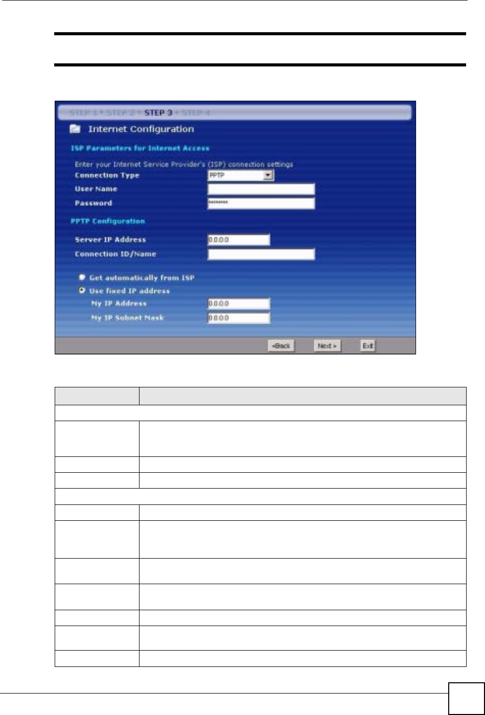
Chapter 4 Connection Wizard
NBG-460N User’s Guide 57
"The NBG-460N supports one PPTP server connection at any given time.
Figure 23 Wizard Step 3: PPTP Connection
The following table describes the fields in this screen
Table 16 Wizard Step 3: PPTP Connection
LABEL DESCRIPTION
ISP Parameters for Internet Access
Connection Type Select PPTP from the drop-down list box. To configure a PPTP client, you must
configure the User Name and Password fields for a PPP connection and the
PPTP parameters for a PPTP connection.
User Name Type the user name given to you by your ISP.
Password Type the password associated with the User Name above.
PPTP Configuration
Server IP Address Type the IP address of the PPTP server.
Connection ID/
Name Enter the connection ID or connection name in this field. It must follow the "c:id"
and "n:name" format. For example, C:12 or N:My ISP.
This field is optional and depends on the requirements of your ISP.
Get automatically
from ISP Select this radio button if your ISP did not assign you a fixed IP address.
Use fixed IP
address Select this radio button, provided by your ISP to give the NBG-460N a fixed,
unique IP address.
My IP Address Type the (static) IP address assigned to you by your ISP.
My IP Subnet
Mask Type the subnet mask assigned to you by your ISP (if given).
Back Click Back to return to the previous screen.
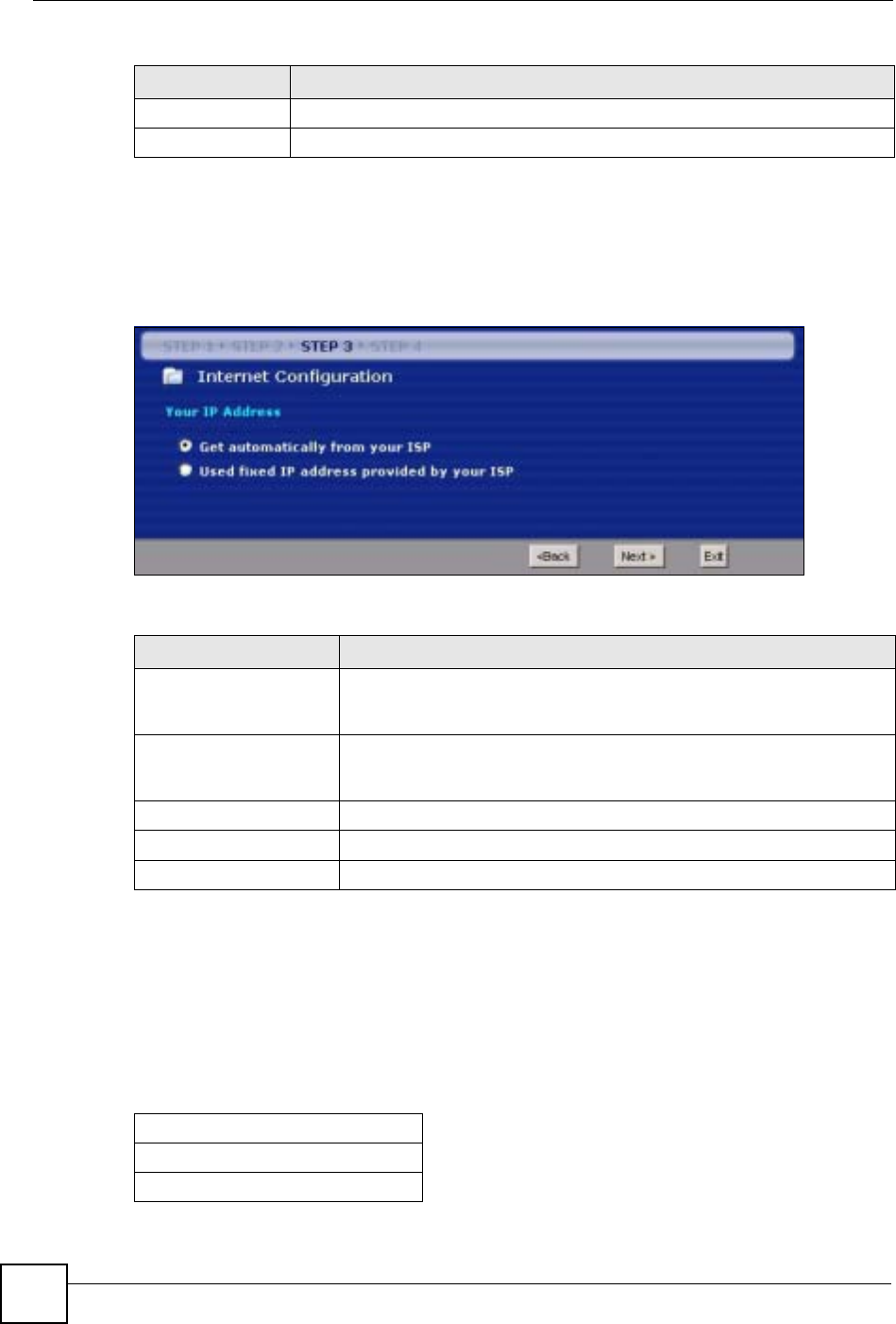
Chapter 4 Connection Wizard
NBG-460N User’s Guide
58
4.4.4 Your IP Address
The following wizard screen allows you to assign a fixed IP address or give the NBG-460N an
automatically assigned IP address depending on your ISP.
Figure 24 Wizard Step 3: Your IP Address
The following table describes the labels in this screen
4.4.5 WAN IP Address Assignment
Every computer on the Internet must have a unique IP address. If your networks are isolated
from the Internet, for instance, only between your two branch offices, you can assign any IP
addresses to the hosts without problems. However, the Internet Assigned Numbers Authority
(IANA) has reserved the following three blocks of IP addresses specifically for private
networks.
Next Click Next to continue.
Exit Click Exit to close the wizard screen without saving.
Table 16 Wizard Step 3: PPTP Connection
LABEL DESCRIPTION
Table 17 Wizard Step 3: Your IP Address
LABEL DESCRIPTION
Get automatically from
your ISP Select this option If your ISP did not assign you a fixed IP address. This is
the default selection. If you choose this option, skip directly to Section
4.4.9 on page 61.
Use fixed IP address
provided by your ISP Select this option if you were given IP address and/or DNS server settings
by the ISP. The fixed IP address should be in the same subnet as your
broadband modem or router.
Back Click Back to return to the previous screen.
Next Click Next to continue.
Exit Click Exit to close the wizard screen without saving.
Table 18 Private IP Address Ranges
10.0.0.0 -10.255.255.255
172.16.0.0 -172.31.255.255
192.168.0.0 -192.168.255.255

Chapter 4 Connection Wizard
NBG-460N User’s Guide 59
You can obtain your IP address from the IANA, from an ISP or have it assigned by a private
network. If you belong to a small organization and your Internet access is through an ISP, the
ISP can provide you with the Internet addresses for your local networks. On the other hand, if
you are part of a much larger organization, you should consult your network administrator for
the appropriate IP addresses.
"Regardless of your particular situation, do not create an arbitrary IP address;
always follow the guidelines above. For more information on address
assignment, please refer to RFC 1597, Address Allocation for Private Internets
and RFC 1466, Guidelines for Management of IP Address Space.
4.4.6 IP Address and Subnet Mask
Similar to the way houses on a street share a common street name, so too do computers on a
LAN share one common network number.
Where you obtain your network number depends on your particular situation. If the ISP or
your network administrator assigns you a block of registered IP addresses, follow their
instructions in selecting the IP addresses and the subnet mask.
If the ISP did not explicitly give you an IP network number, then most likely you have a single
user account and the ISP will assign you a dynamic IP address when the connection is
established. The Internet Assigned Number Authority (IANA) reserved this block of addresses
specifically for private use; please do not use any other number unless you are told otherwise.
Let's say you select 192.168.1.0 as the network number; which covers 254 individual
addresses, from 192.168.1.1 to 192.168.1.254 (zero and 255 are reserved). In other words, the
first three numbers specify the network number while the last number identifies an individual
computer on that network.
Once you have decided on the network number, pick an IP address that is easy to remember,
for instance, 192.168.1.1, for your NBG-460N, but make sure that no other device on your
network is using that IP address.
The subnet mask specifies the network number portion of an IP address. Your NBG-460N will
compute the subnet mask automatically based on the IP address that you entered. You don't
need to change the subnet mask computed by the NBG-460N unless you are instructed to do
otherwise.
4.4.7 DNS Server Address Assignment
Use DNS (Domain Name System) to map a domain name to its corresponding IP address and
vice versa, for instance, the IP address of www.zyxel.com is 204.217.0.2. The DNS server is
extremely important because without it, you must know the IP address of a computer before
you can access it.
The NBG-460N can get the DNS server addresses in the following ways.
1The ISP tells you the DNS server addresses, usually in the form of an information sheet,
when you sign up. If your ISP gives you DNS server addresses, enter them in the DNS
Server fields in the Wizard and/or WAN > Internet Connection screen.
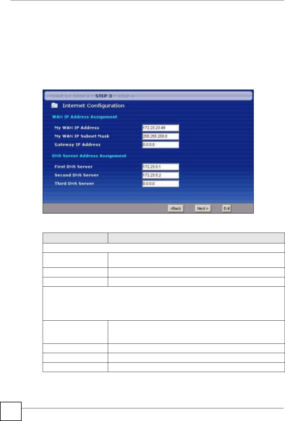
Chapter 4 Connection Wizard
NBG-460N User’s Guide
60
2If the ISP did not give you DNS server information, leave the DNS Server fields set to
0.0.0.0 in the Wizard screen and/or set to From ISP in the WAN > Internet
Connection screen for the ISP to dynamically assign the DNS server IP addresses.
4.4.8 WAN IP and DNS Server Address Assignment
The following wizard screen allows you to assign a fixed WAN IP address and DNS server
addresses.
Figure 25 Wizard Step 3: WAN IP and DNS Server Addresses
The following table describes the labels in this screen
Table 19 Wizard Step 3: WAN IP and DNS Server Addresses
LABEL DESCRIPTION
WAN IP Address Assignment
My WAN IP Address Enter your WAN IP address in this field. The WAN IP address should be in
the same subnet as your DSL/Cable modem or router.
My WAN IP Subnet Mask Enter the IP subnet mask in this field.
Gateway IP Address Enter the gateway IP address in this field.
System DNS Server Address Assignment (if applicable)
DNS (Domain Name System) is for mapping a domain name to its corresponding IP address and vice
versa. The DNS server is extremely important because without it, you must know the IP address of a
computer before you can access it. The NBG-460N uses a system DNS server (in the order you
specify here) to resolve domain names for DDNS and the time server.
First DNS Server
Second DNS Server
Third DNS Server
Enter the DNS server's IP address in the fields provided.
If you do not configure a system DNS server, you must use IP addresses
when configuring DDNS and the time server.
Back Click Back to return to the previous screen.
Next Click Next to continue.
Exit Click Exit to close the wizard screen without saving.
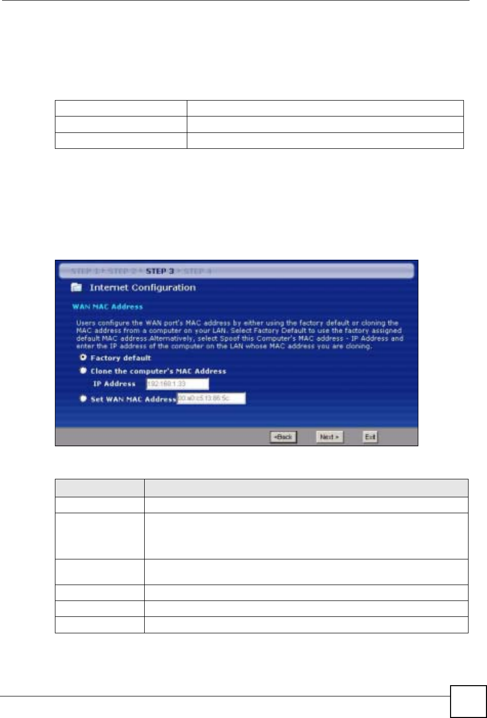
Chapter 4 Connection Wizard
NBG-460N User’s Guide 61
4.4.9 WAN MAC Address
Every Ethernet device has a unique MAC (Media Access Control) address. The MAC address
is assigned at the factory and consists of six pairs of hexadecimal characters, for example,
00:A0:C5:00:00:02.
This screen allows users to configure the WAN port's MAC address by either using the NBG-
460N’s MAC address, copying the MAC address from a computer on your LAN or manually
entering a MAC address. Once it is successfully configured, the address will be copied to the
"rom" file (ZyNOS configuration file). It will not change unless you change the setting or
upload a different "rom" file. It is advisable to clone the MAC address from a computer on
your LAN even if your ISP does not presently require MAC address authentication.
Figure 26 Wizard Step 3: WAN MAC Address
The following table describes the fields in this screen.
Table 20 Example of Network Properties for LAN Servers with Fixed IP Addresses
Choose an IP address 192.168.1.2-192.168.1.32; 192.168.1.65-192.168.1.254.
Subnet mask 255.255.255.0
Gateway (or default route) 192.168.1.1(NBG-460N LAN IP)
Table 21 Wizard Step 3: WAN MAC Address
LABEL DESCRIPTION
Factory Default Select Factory Default to use the factory assigned default MAC address.
Clone the
computer’s MAC
address
Select this option and enter the IP address of the computer on the LAN whose
MAC you are cloning. It is advisable to clone the MAC address from a computer
on your LAN even if your ISP does not presently require MAC address
authentication.
Set WAN MAC
Address Select this option and enter the MAC address you want to use.
Back Click Back to return to the previous screen.
Next Click Next to continue.
Exit Click Exit to close the wizard screen without saving.
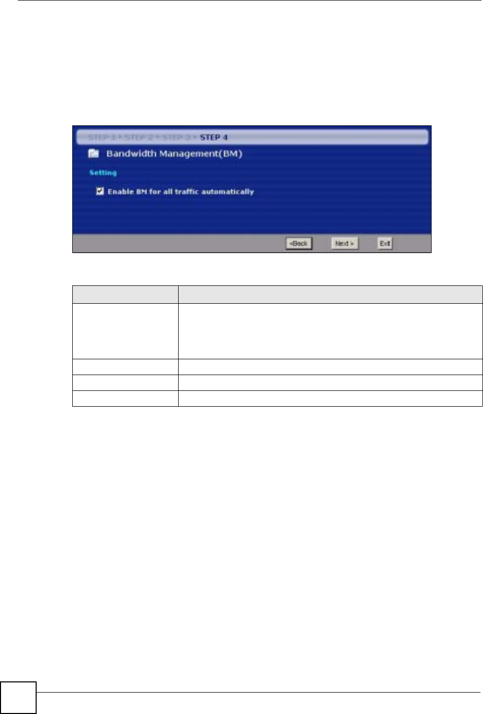
Chapter 4 Connection Wizard
NBG-460N User’s Guide
62
4.5 Connection Wizard: STEP 4: Bandwidth management
Bandwidth management allows you to control the amount of bandwidth going out through the
NBG-460N’s WAN, LAN or WLAN port and prioritize the distribution of the bandwidth
according to the traffic type. This helps keep one service from using all of the available
bandwidth and shutting out other users.
Figure 27 Wizard Step 4: Bandwidth Management
The following fields describe the label in this screen.
4.6 Connection Wizard Complete
Click Apply to save your configuration.
Table 22 Wizard Step 4: Bandwidth Management
LABEL DESCRIPTION
Enable BM for all traffic
automatically Select the check box to have the NBG-460N apply bandwidth management
to traffic going out through the NBG-460N’s WAN, LAN, HomePlug AV or
WLAN port. Bandwidth is allocated according to the traffic type
automatically. Real-time packets, such as VoIP traffic always get higher
priority.
Back Click Back to return to the previous screen.
Next Click Next to continue.
Exit Click Exit to close the wizard screen without saving.
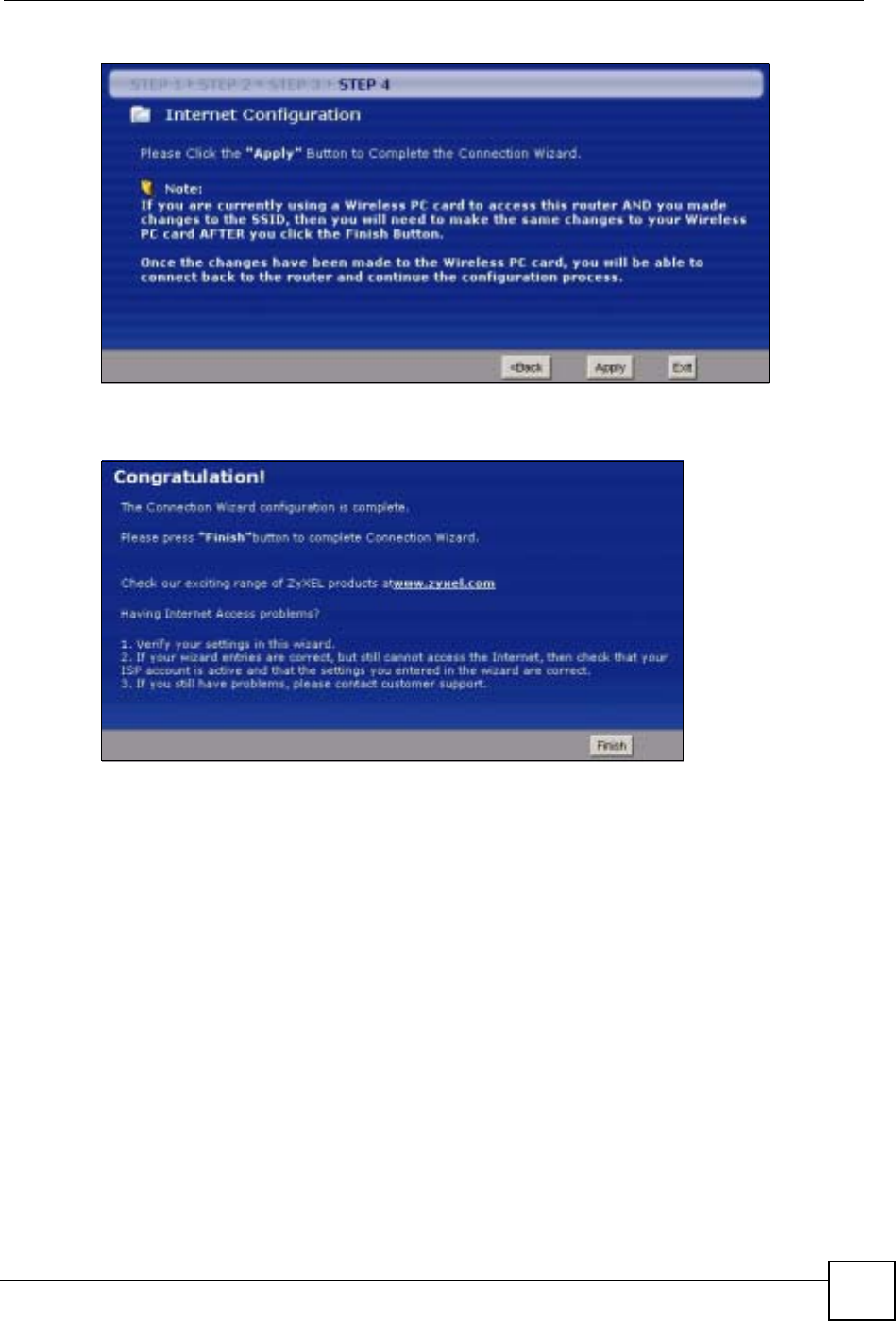
Chapter 4 Connection Wizard
NBG-460N User’s Guide 63
Figure 28 Connection Wizard Save
Follow the on-screen instructions and click Finish to complete the wizard setup.
Figure 29 Connection Wizard Complete
Well done! You have successfully set up your NBG-460N to operate on your network and
access the Internet.

Chapter 4 Connection Wizard
NBG-460N User’s Guide
64
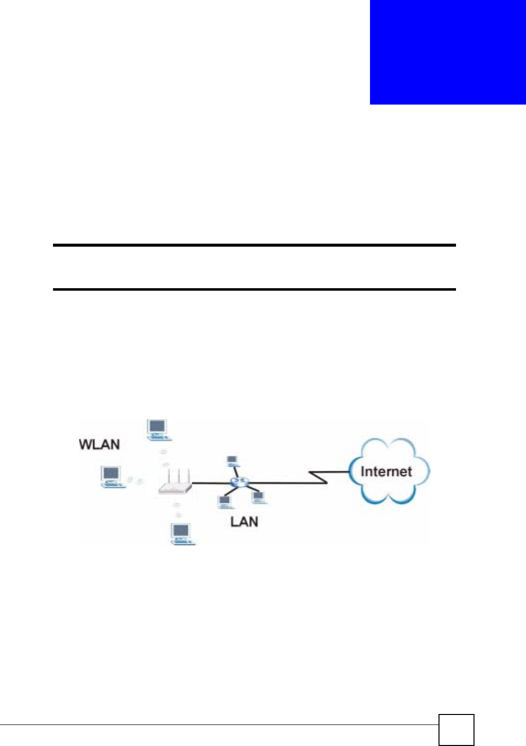
NBG-460N User’s Guide 65
CHAPTER 5
AP Mode
This chapter discusses how to configure settings while your NBG-460N is set to AP Mode.
Many screens that are available in Router Mode are not available in AP Mode.
"See Chapter 6 on page 73 for an example of setting up a wireless network in
AP mode.
5.1 AP Mode Overview
Use your NBG-460N as an AP if you already have a router or gateway on your network. In
this mode your device bridges a wired network (LAN) and wireless LAN (WLAN) in the same
subnet. See the figure below for an example.
Figure 30 Wireless Internet Access in AP Mode
5.2 Setting your NBG-460N to AP Mode
1Log into the web configurator if you haven’t already. See the Quick start Guide for
instructions on how to do this.
2To set your NBG-460N to AP Mode, go to Maintenance > Sys OP Mode > General
and select Access Point.
AB
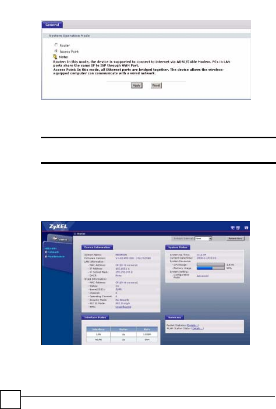
Chapter 5 AP Mode
NBG-460N User’s Guide
66
Figure 31 Maintenance > Sys OP Mode > General
3A pop-up appears providing information on this mode. Click OK in the pop-up message
window. (See Section 24.2 on page 260 for more information on the pop-up.) Click
Apply. Your NBG-460N is now in AP Mode.
"You do not have to log in again or restart your device when you change
modes.
5.3 The Status Screen in AP Mode
Click on Status. The screen below shows the status screen in AP Mode.
Figure 32 Status: AP Mode

Chapter 5 AP Mode
NBG-460N User’s Guide 67
The following table describes the labels shown in the Status screen.
Table 23 Web Configurator Status Screen
LABEL DESCRIPTION
Device Information
System Name This is the System Name you enter in the Maintenance > System > General
screen. It is for identification purposes.
Firmware Version This is the firmware version and the date created.
LAN Information
- MAC Address This shows the LAN Ethernet adapter MAC Address of your device.
- IP Address This shows the LAN port’s IP address.
- IP Subnet Mask This shows the LAN port’s subnet mask.
- DHCP This shows the LAN port’s DHCP role - Client or None.
WLAN Information
- MAC Address This shows the wireless adapter MAC Address of your device.
- Status This shows the current status of the Wireless LAN - On,Off or Off by scheduler.
- Name (SSID) This shows a descriptive name used to identify the NBG-460N in the wireless LAN.
- Channel This shows the channel number which you select manually.
- Operating Channel This shows the channel number which the NBG-460N is currently using over the
wireless LAN.
- Security Mode This shows the level of wireless security the NBG-460N is using.
- 802.11 Mode This shows the IEEE 802.11 standard that the NBG-460N supports. Wireless clients
must support the same standard in order to be able to connect to the NBG-460N
- WPS This shows the WPS (WiFi Protected Setup) Status. Click the status to display
Network > Wireless LAN > WPS screen.
System Status
System Uptime This is the total time the NBG-460N has been on.
Current Date/Time This field displays your NBG-460N’s present date and time.
System Resource
- CPU Usage This displays what percentage of the NBG-460N’s processing ability is currently
used. When this percentage is close to 100%, the NBG-460N is running at full load,
and the throughput is not going to improve anymore. If you want some applications to
have more throughput, you should turn off other applications (for example, using
bandwidth management).
- Memory Usage This shows what percentage of the heap memory the NBG-460N is using. Heap
memory refers to the memory that is not used by ZyNOS (ZyXEL Network Operating
System) and is thus available for running processes like NAT and the firewall.
System Setting
- Configuration Mode This shows whether the advanced screens of each feature are turned on
(Advanced) or not (Basic).
Interface Status
Interface This displays the NBG-460N port types. The port types are: LAN and WLAN.
Status For the LAN port, this field displays Down (line is down) or Up (line is up or
connected).
For the WLAN, it displays Up when the WLAN is enabled or Down when the WLAN
is disabled.
Chapter 5 AP Mode
NBG-460N User’s Guide
68
5.3.1 Navigation Panel
Use the menu in the navigation panel to configure NBG-460N features in AP Mode.
The following screen and table show the features you can configure in AP Mode.
Figure 33 Menu: AP Mode
The following table describes the sub-menus.
Rate For the LAN ports, this displays the port speed and duplex setting or N/A when the
line is disconnected.
For the WLAN, it displays the maximum transmission rate when the WLAN is
enabled and N/A when the WLAN is disabled.
Summary
Packet Statistics Use this screen to view port status and packet specific statistics.
WLAN Station Status Use this screen to view the wireless stations that are currently associated to the
NBG-460N.
Table 23 Web Configurator Status Screen (continued)
LABEL DESCRIPTION
Table 24 Screens Summary
LINK TAB FUNCTION
Status This screen shows the NBG-460N’s general device, system and
interface status information. Use this screen to access the wizard,
and summary statistics tables.
Network

Chapter 5 AP Mode
NBG-460N User’s Guide 69
5.4 Configuring Your Settings
5.4.1 LAN Settings
Use this section to configure your LAN settings while in AP Mode.
Click Network > LAN to see the screen below.
Wireless
LAN General Use this screen to configure wireless LAN.
MAC Filter Use the MAC filter screen to configure the NBG-460N to block
access to devices or block the devices from accessing the NBG-
460N.
Advanced This screen allows you to configure advanced wireless settings.
QoS Use this screen to configure Wi-Fi Multimedia Quality of Service
(WMM QoS). WMM QoS allows you to prioritize wireless traffic
according to the delivery requirements of individual services.
WPS Use this screen to configure WPS.
WPS Station Use this screen to add a wireless station using WPS.
Scheduling Use this screen to schedule the times the Wireless LAN is enabled.
LAN IP Use this screen to configure LAN IP address and subnet mask or to
get the LAN IP address from a DHCP server.
Maintenance
System General Use this screen to view and change administrative settings such as
system and domain names, password and inactivity timer.
Time Setting Use this screen to change your NBG-460N’s time and date.
Logs View Log Use this screen to view the logs for the categories that you
selected.
Log Settings Use this screen to change your NBG-460N’s log settings.
Tools Firmware Use this screen to upload firmware to your NBG-460N.
Configuration Use this screen to backup and restore the configuration or reset
the factory defaults to your NBG-460N.
Restart This screen allows you to reboot the NBG-460N without turning the
power off.
Wake On
LAN Use this screen to remotely turn on a device on the network.
Config Mode General This screen allows you to display or hide the advanced screens or
features.
Sys OP
Mode General This screen allows you to select whether your device acts as a
Router or a Access Point.
Language This screen allows you to select the language you prefer.
Table 24 Screens Summary
LINK TAB FUNCTION
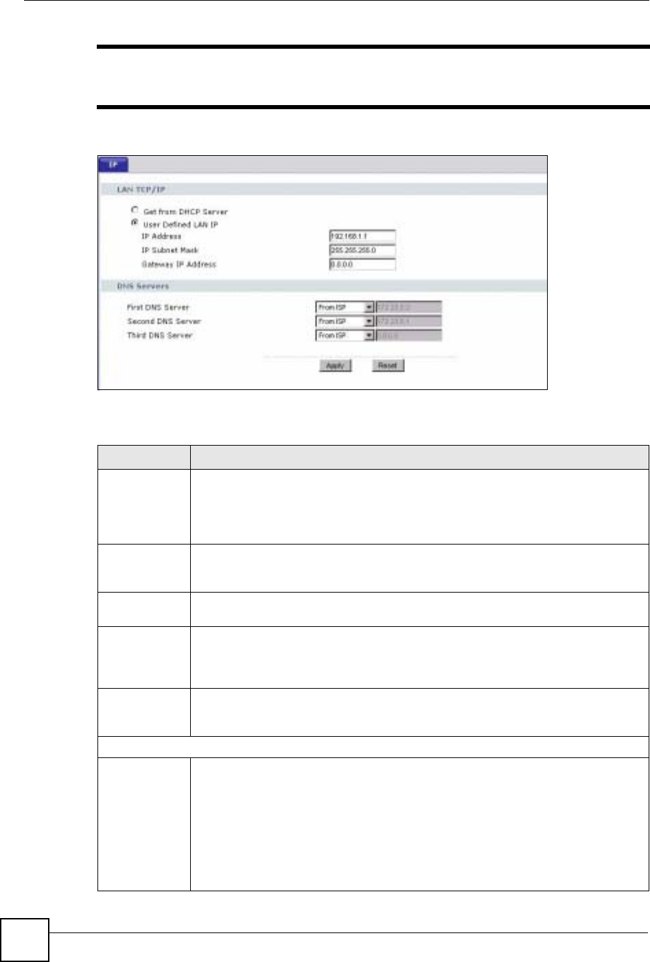
Chapter 5 AP Mode
NBG-460N User’s Guide
70
"If you change the IP address of the NBG-460N in the screen below, you will
need to log into the NBG-460N again using the new IP address.
Figure 34 Network > LAN > IP
The table below describes the labels in the screen.
Table 25 Network > LAN > IP
LABEL DESCRIPTION
Get from
DHCP Server Select this option to allow the NBG-460N to obtain an IP address from a DHCP
server on the network. You must connect the WAN port to a device with a DHCP
server enabled (such as a router or gateway). Without a DHCP server the NBG-
460N will have no IP address. You need to find out the IP address the DHCP server
assigns to the NBG-460N and use that address to log in to the NBG-460N again.
User Defined
LAN IP Select this option to set the NBG-460N’s IP address. This setting is selected by
default. Check the IP address is on the same domain as other devices on your
network.
IP Address Type the IP address in dotted decimal notation. The default setting is 192.168.1.1. If
you change the IP address you will have to log in again with the new IP address.
IP Subnet
Mask The subnet mask specifies the network number portion of an IP address. Your NBG-
460N will automatically calculate the subnet mask based on the IP address that you
assign. Unless you are implementing subnetting, use the subnet mask computed by
the NBG-460N.
Gateway IP
Address Type the IP address of the gateway. The gateway is an immediate neighbor of your
NBG-460N that will forward the packet to the destination. In AP Mode, the gateway
must be a router on the same segment as your NBG-460N.
DNS Servers
First DNS
Server
Second DNS
Server
Third DNS
Server
Select From ISP if your ISP dynamically assigns DNS server information. The field
to the right displays the (read-only) DNS server IP address that the ISP assigns.
Select User-Defined if you have the IP address of a DNS server. Enter the DNS
server's IP address in the field to the right. If you chose User-Defined, but leave the
IP address set to 0.0.0.0, User-Defined changes to None after you click Apply. If
you set a second choice to User-Defined, and enter the same IP address, the
second User-Defined changes to None after you click Apply.
Select None if you do not want to configure DNS servers. If you do not configure a
DNS server, you must know the IP address of a computer in order to access it.

Chapter 5 AP Mode
NBG-460N User’s Guide 71
5.4.2 WLAN and Maintenance Settings
The configuration of wireless and maintenance settings in AP Mode is the same as for Router
Mode.
• See Chapter 5 on page 69 for information on the configuring your wireless network.
• See Maintenance and Troubleshooting (227) for information on the configuring your
Maintenance settings.
5.5 Logging in to the Web Configurator in AP Mode
1Connect your computer to the LAN port of the NBG-460N.
2The default IP address if the NBG-460N is “192.168.1.1”. In this case, your computer
must have an IP address in the range between “192.168.1.2” and “192.168.1.255”.
3Click Start > Run on your computer in Windows.
4Type “cmd” in the dialog box.
5Type “ipconfig” to show your computer’s IP address. If your computer’s IP address is
not in the correct range then see Appendix D on page 293 for information on changing
your computer’s IP address.
6After you’ve set your computer’s IP address, open a web browser such as Internet
Explorer and type “192.168.1.1” as the web address in your web browser.
See Chapter 6 on page 73 for a tutorial on setting up a network with an AP.
Apply Click Apply to save your changes to the NBG-460N.
Reset Click Reset to reload the previous configuration for this screen.
LABEL DESCRIPTION

Chapter 5 AP Mode
NBG-460N User’s Guide
72
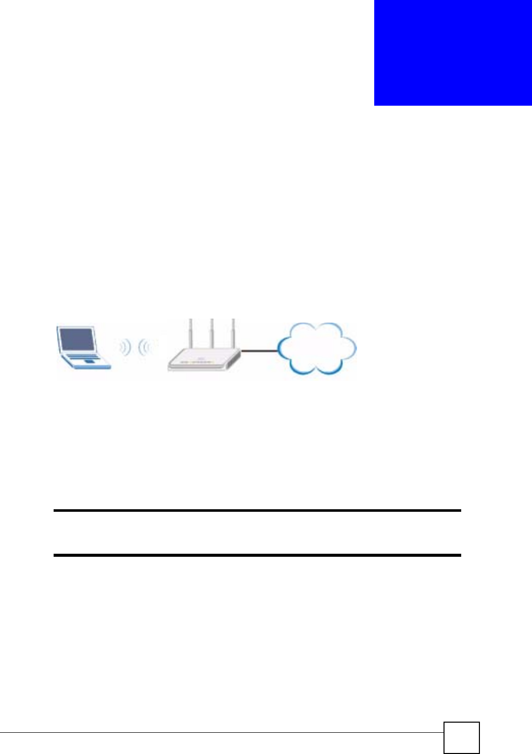
NBG-460N User’s Guide 73
CHAPTER 6
Tutorials
6.1 Wireless Tutorials
6.1.1 How to Connect to the Internet from an AP
This section gives you an example of how to set up an access point (AP) and wireless client (a
notebook (B), in this example) for wireless communication. B can access the Internet through
the AP wirelessly.
Figure 35 Wireless AP Connection to the Internet
6.1.2 Configure Wireless Security Using WPS on both your NBG-460N
and Wireless Client
This section gives you an example of how to set up wireless network using WPS. This
example uses the NBG-460N as the AP and NWD210N as the wireless client which connects
to a notebook.
"The wireless client must be a WPS-aware device (for example, a WPS USB
adapter or PCI card).
There are two WPS methods for creating a secure connection. This tutorial shows you how to
do both.
•Push Button Configuration (PBC) - create a secure wireless network simply by pressing
a button. See Section 6.1.2.1 on page 74.This is the easier method.
•PIN Configuration - create a secure wireless network simply by entering a wireless
client's PIN (Personal Identification Number) in the NBG-460N’s interface. See Section
6.1.2.2 on page 75. This is the more secure method, since one device can authenticate the
other.
BAP
Internet

Chapter 6 Tutorials
NBG-460N User’s Guide
74
6.1.2.1 Push Button Configuration (PBC)
1Make sure that your NBG-460N is turned on and that it is within range of your
computer.
2Make sure that you have installed the wireless client (this example uses the NWD210N)
driver and utility in your notebook.
3In the wireless client utility, find the WPS settings. Enable WPS and press the WPS
button (Start or WPS button)
4Log into NBG-460N’s web configurator and press the Push Button button in the
Network > Wireless Client >WPS Station screen.
"Your NBG-460N has a WPS button located on its panel, as well as a WPS
button in its configuration utility. Both buttons have exactly the same function;
you can use one or the other.
"It doesn’t matter which button is pressed first. You must press the second
button within two minutes of pressing the first one.
The NBG-460N sends the proper configuration settings to the wireless client. This may take
up to two minutes. Then the wireless client is able to communicate with the NBG-460N
securely.
The following figure shows you an example to set up wireless network and security by
pressing a button on both NBG-460N and wireless client (the NWD210N in this example).
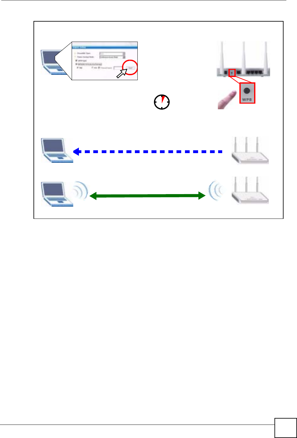
Chapter 6 Tutorials
NBG-460N User’s Guide 75
Figure 36 Example WPS Process: PBC Method
6.1.2.2 PIN Configuration
When you use the PIN configuration method, you need to use both NBG-460N’s configuration
interface and the client’s utilities.
1Launch your wireless client’s configuration utility. Go to the WPS settings and select the
PIN method to get a PIN number.
2Enter the PIN number to the PIN field in the Network > Wireless LAN >WPS Station
screen on the NBG-460N.
3Click Start buttons (or button next to the PIN field) on both the wireless client utility
screen and the NBG-460N’s WPS Station screen within two minutes.
The NBG-460N authenticates the wireless client and sends the proper configuration settings to
the wireless client. This may take up to two minutes. Then the wireless client is able to
communicate with the NBG-460N securely.
The following figure shows you the example to set up wireless network and security on NBG-
460N and wireless client (ex. NWD210N in this example) by using PIN method.
Wireless Client NBG-460N
SECURITY INFO
COMMUNICATION
WITHIN 2 MINUTES
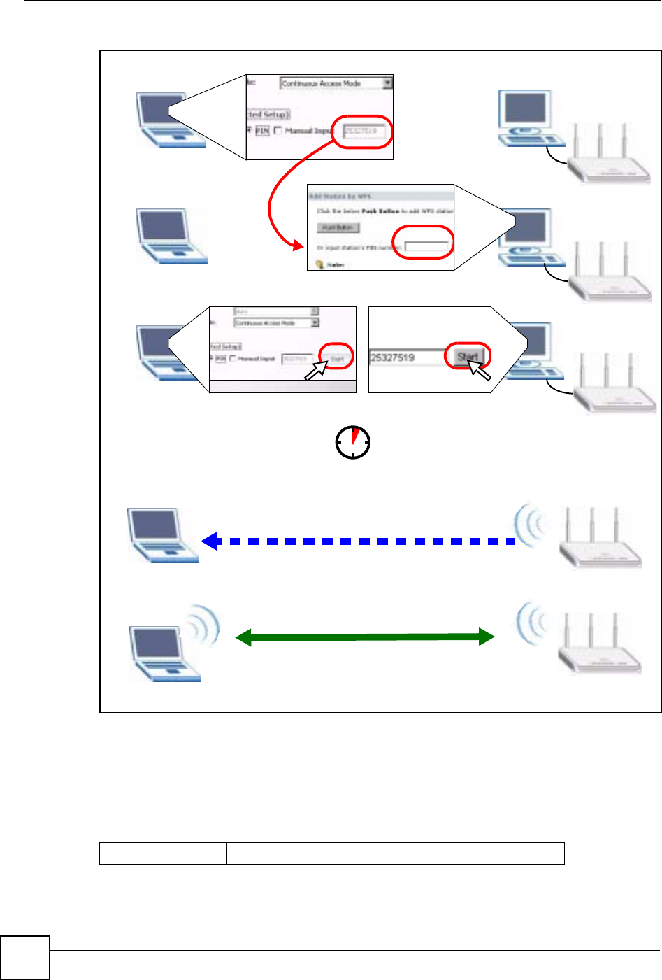
Chapter 6 Tutorials
NBG-460N User’s Guide
76
Figure 37 Example WPS Process: PIN Method
6.1.3 Enable and Configure Wireless Security without WPS on your
NBG-460N
This example shows you how to configure wireless security settings with the following
parameters on your NBG-460N.
Authentication by PIN
SECURITY INFO
WITHIN 2 MINUTES
Wireless Client
NBG-460N
COMMUNICATION
SSID SSID_Example3
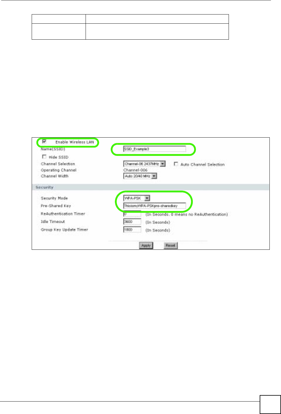
Chapter 6 Tutorials
NBG-460N User’s Guide 77
Follow the steps below to configure the wireless settings on your NBG-460N.
The instructions require that your hardware is connected (see the Quick Start Guide) and you
are logged into the web configurator through your LAN connection (see Section 3.2 on page
37).
1Open the Wireless LAN > General screen in the AP’s web configurator.
2Make sure the Enable Wireless LAN check box is selected.
3Enter SSID_Example3 as the SSID and select a channel.
4Set security mode to WPA-PSK and enter ThisismyWPA-PSKpre-sharedkey in the
Pre-Shared Key field. Click Apply.
Figure 38 Network > Wireless LAN > General
5Open the Status screen. Verify your wireless and wireless security settings under Device
Information and check if the WLAN connection is up under Interface Status.
Channel 6
Security WPA-PSK
(Pre-Shared Key: ThisismyWPA-PSKpre-sharedkey)
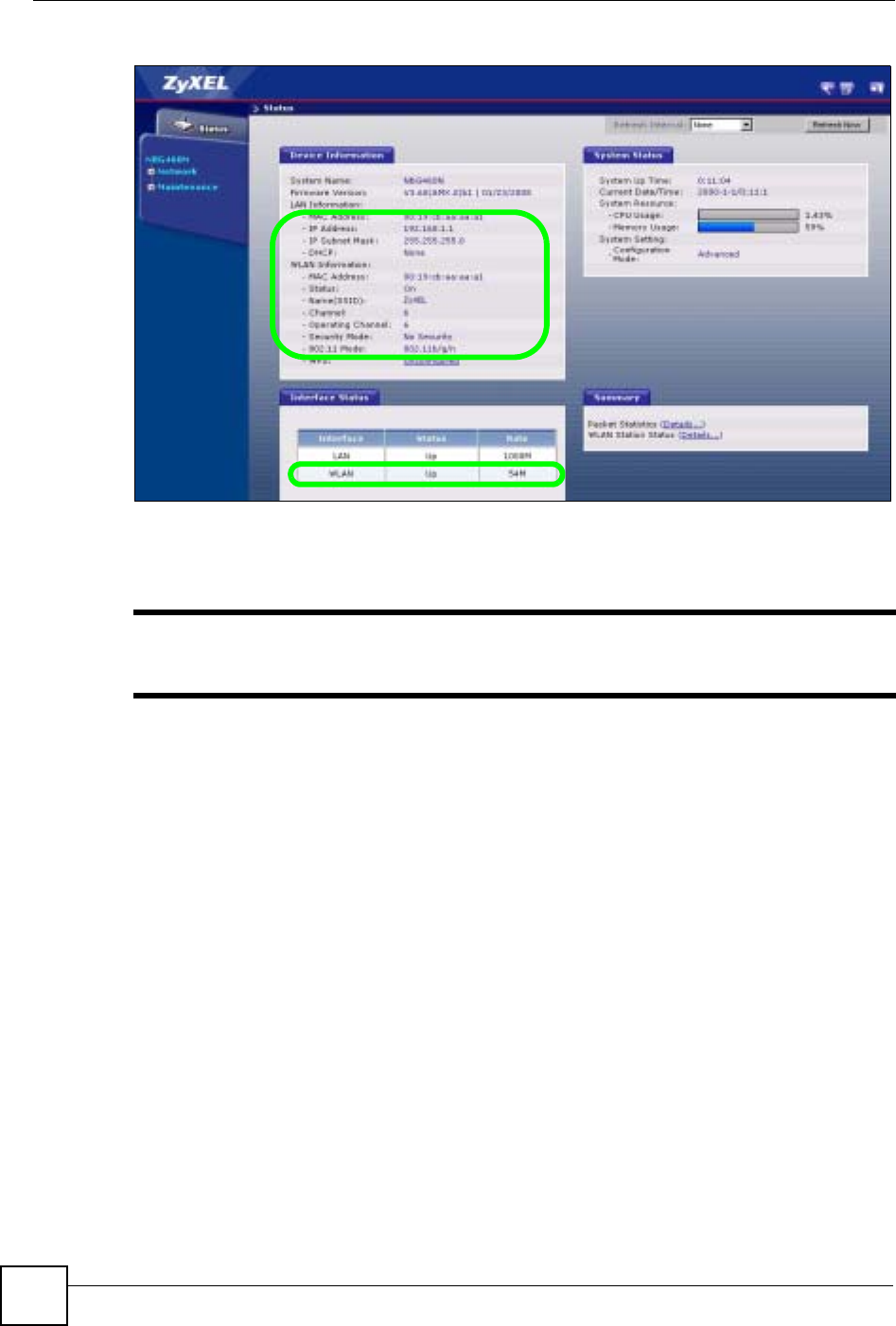
Chapter 6 Tutorials
NBG-460N User’s Guide
78
Figure 39 Status: AP Mode
6.1.4 Configure Your Notebook
"We use the ZyXEL M-302 wireless adapter utility screens as an example for
the wireless client. The screens may vary for different models.
1The NBG-460N supports IEEE 802.11b, IEEE 802.11g and IEEE 802.11n wireless
clients. Make sure that your notebook or computer’s wireless adapter supports one of
these standards.
2Wireless adapters come with software sometimes called a “utility” that you install on
your computer. See your wireless adapter’s User’s Guide for information on how to do
that.
3After you’ve installed the utility, open it. If you cannot see your utility’s icon on your
screen, go to Start > Programs and click on your utility in the list of programs that
appears. The utility displays a list of APs within range, as shown in the example screen
below.
4Select SSID_Example3 and click Connect.
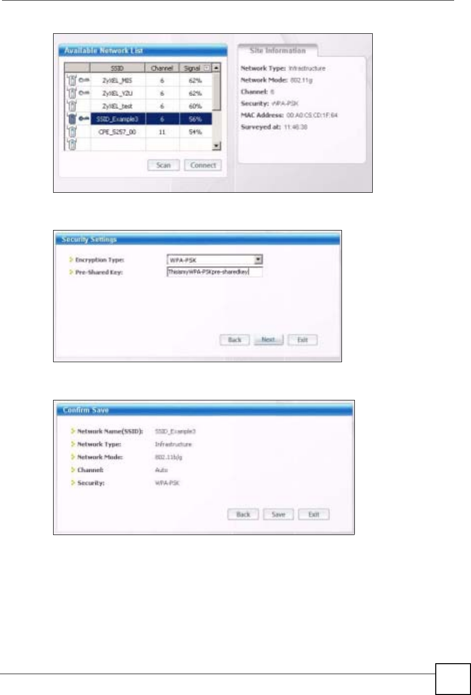
Chapter 6 Tutorials
NBG-460N User’s Guide 79
Figure 40 Connecting a Wireless Client to a Wireless Network t
5Select WPA-PSK and type the security key in the following screen. Click Next.
Figure 41 Security Settings
6The Confirm Save window appears. Check your settings and click Save to continue.
Figure 42 Confirm Save
7Check the status of your wireless connection in the screen below. If your wireless
connection is weak or you have no connection, see the Troubleshooting section of this
User’s Guide.
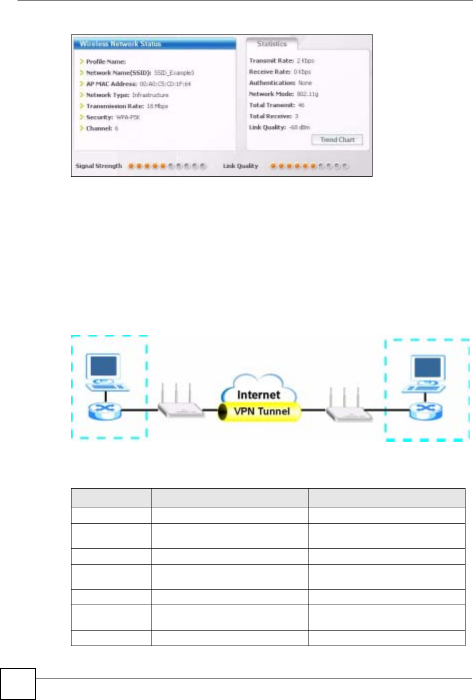
Chapter 6 Tutorials
NBG-460N User’s Guide
80
Figure 43 Link Status
8If your connection is successful, open your Internet browser and enter http://
www.zyxel.com or the URL of any other web site in the address bar. If you are able to
access the web site, your wireless connection is successfully configured.
6.2 Site-To-Site VPN Tunnel Tutorial
Bob and Jack want to setup a VPN connection between their offices. Bob and Jack each have a
NBG-460N router and a static WAN IP address. This tutorial covers how to configure their
NBG-460Ns to create a secure connection.
Figure 44 Site-To-Site VPN Tunnel
The following table describes the VPN settings that must be configured on Bob and Jack’s
NBG-460N routers.
Table 26 Site-To-Site VPN Tunnel Settings
SETTING BOB’S NBG-460N JACK’S NBG-460N
Active YES YES
IPSec Keying
Mode IKE IKE
Local Address 192.168.1.35 10.0.0.7
Local Address End
/Mask 192.168.1.35 10.0.0.7
Remote Address 10.0.0.7 192.168.1.35
Remote Address
End /Mask 10.0.0.7 192.168.1.35
My IP Address 1.1.1.1 2.2.2.2
192.168.1.35 10.0.0.7
BOB JACK
1.1.1.1 2.2.2.2
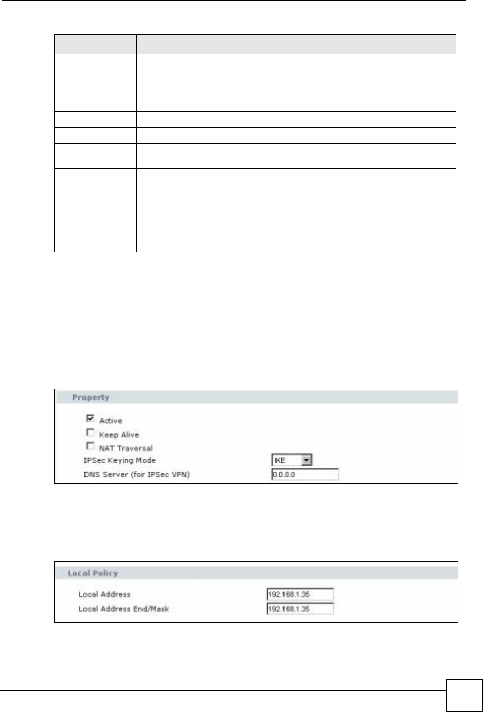
Chapter 6 Tutorials
NBG-460N User’s Guide 81
6.2.1 Configuring Bob’s NBG-460N VPN Settings
To configure these settings Bob uses the NBG-460N web configurator.
1Log into the NBG-460N web configurator and click VPN > Modify icon. This displays
the VPN Rule Setup (basic) screen.
2Select the Active checkbox to enable the VPN rule after it has been created. Make sure
IKE is selected as the IPSec Keying Mode.
Figure 45 Property
3Enter the IP address “192.168.1.35” in the Local Address text box. This is the IP
address of Bob’s computer. Enter the IP address “192.168.1.35” in the Local Address
End/Mask text box. This value is the same as Bob only wants Jack to access this single
IP address.
Figure 46 Local Policy
4Enter the IP address “10.0.0.7” in the Remote Address Start text box. This is the IP
address of Jack’s computer. Enter the IP address “10.0.0.7” in the Remote Address
Local ID Type IP IP
Local Content 1.1.1.1 2.2.2.2
Secure Gateway
Address 2.2.2.2 1.1.1.1
Peer ID Type IP IP
Peer Content 2.2.2.2 1.1.1.1
Encapsulation
Mode Tunnel Tunnel
IPSec Protocol ESP ESP
Pre-Shared Key ThisIsMySecretKey ThisIsMySecretKey
Encryption
Algorithm 3DES 3DES
Authentication
Algorithm SHA1 SHA1
Table 26 Site-To-Site VPN Tunnel Settings (continued)
SETTING BOB’S NBG-460N JACK’S NBG-460N
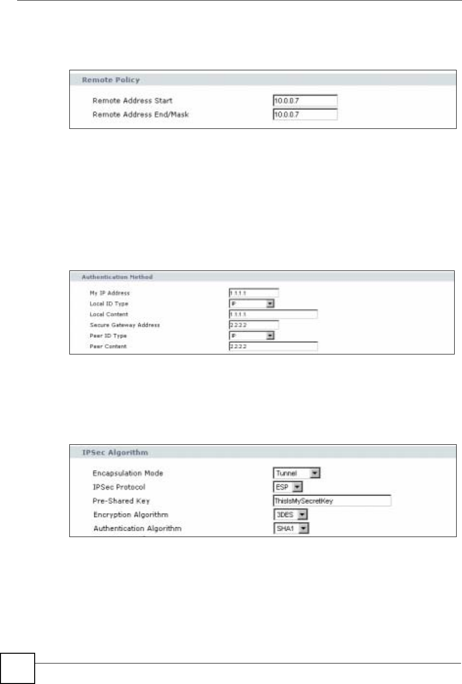
Chapter 6 Tutorials
NBG-460N User’s Guide
82
End/Mask text box. This value is the same as Jack only wants Bob to access this single
IP address.
Figure 47 Remote Policy
5Enter the IP address “1.1.1.1” in the My IP Address text box. This is Bob’s WAN IP
address.
6Select IP as the Local ID Type. This is the type of content that will be used to identify
Bob’s NBG-460N. Enter the IP address “1.1.1.1” in the Local Content text box. This
identifies Bob’s NBG-460N to Jack’s NBG-460N.
7Enter the IP address “2.2.2.2” in the Secure Gateway Address text box. This is Jack’s
WAN IP address.
8Select IP as the Peer ID Type. This is Jack’s Local ID Type. Enter “2.2.2.2” in the Peer
Content text box. This is Jack’s Local Content WAN IP address.
Figure 48 Authentication Method
9Select Tunnel as the Encapsulation Mode and ESP as the IPSec Protocol.
10 Enter “ThisIsMySecretKey” as the Pre-Shared Key. This is the password for the VPN
tunnel that only Bob and Jack know.
11 Select 3DES as the encyption algorithm. Select the authentication algorithm as SHA1.
These algorithms are more secure.
Figure 49 IPSec Algorithm
12 Click Apply to save the new rule and click VPN to return to the VPN Summary screen.
The new VPN rule is displayed as shown below.
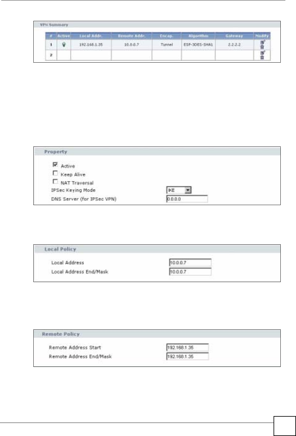
Chapter 6 Tutorials
NBG-460N User’s Guide 83
Figure 50 VPN Summary
6.2.2 Configuring Jack’s NBG-460N VPN Settings
To configure these settings Jack uses the NBG-460N web configurator.
1Log into the NBG-460N web configurator and click VPN > Modify icon. This displays
the VPN Rule Setup (basic) screen.
2Select the Active checkbox to enable the VPN rule after it has been created. Make sure
IKE is selected as the IPSec Keying Mode.
Figure 51 Property
3Enter the IP address “10.0.0.7” in the Local Address text box. This is the IP address of
Jack’s computer. Enter the IP address “10.0.0.7” in the Local Address End/Mask text
box. This value is the same as Jack only wants Bob to access this single IP address.
Figure 52 Local Policy
4Enter the IP address “192.168.1.35” in the Remote Address Start text box. This is the
IP address of Jack’s computer. Enter the IP address “192.168.1.35” in the Remote
Address End/Mask text box. This value is the same as Bob only wants Jack to access
this single IP address.
Figure 53 Remote Policy
5Enter the IP address “2.2.2.2” in the My IP Address text box. This is Jack’s WAN IP
address.
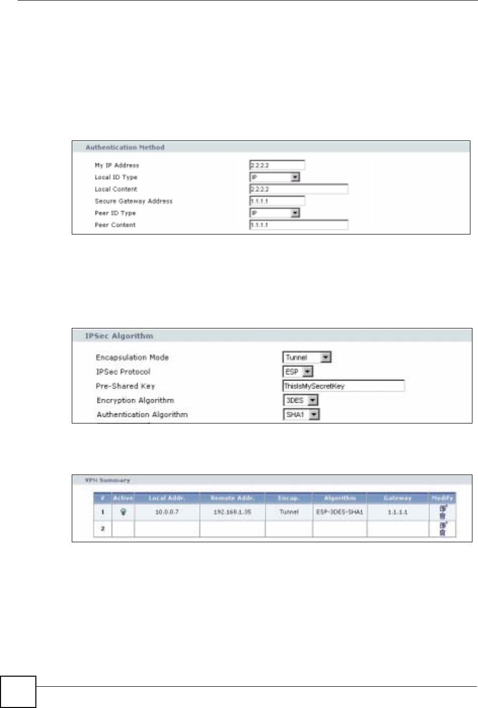
Chapter 6 Tutorials
NBG-460N User’s Guide
84
6Select IP as the Local ID Type. This is the type of content that will be used to identify
Jack’s NBG-460N. Enter the IP address “2.2.2.2” in the Local Content text box. This
identifies Jack’s NBG-460N to Bob’s NBG-460N.
7Enter the IP address “1.1.1.1” in the Secure Gateway Address text box. This is Bob’s
WAN IP address.
8Select IP as the Peer ID Type. This is Bob’s Local ID Type. Enter “1.1.1.1” in the Peer
Content text box. This is Bob’s Local Content WAN IP address.
Figure 54 Authentication Method
9Select Tunnel as the Encapsulation Mode and ESP as the IPSec Protocol.
10 Enter “ThisIsMySecretKey” as the Pre-Shared Key. This is the password for the VPN
tunnel that only Bob and Jack know.
11 Select 3DES as the encyption algorithm. Select the authentication algorithm as SHA1.
These algorithms are more secure.
Figure 55 IPSec Algorithm
12 Click Apply to save the new rule and click VPN in the web configurator menu to return
to the VPN Summary screen. The new VPN rule is displayed as shown below.
Figure 56 VPN Summary
6.2.3 Checking the VPN Connection
Check if the VPN connection is working by pinging the computer on the other side of the VPN
connection. In the example below Bob is pinging Jack’s computer.
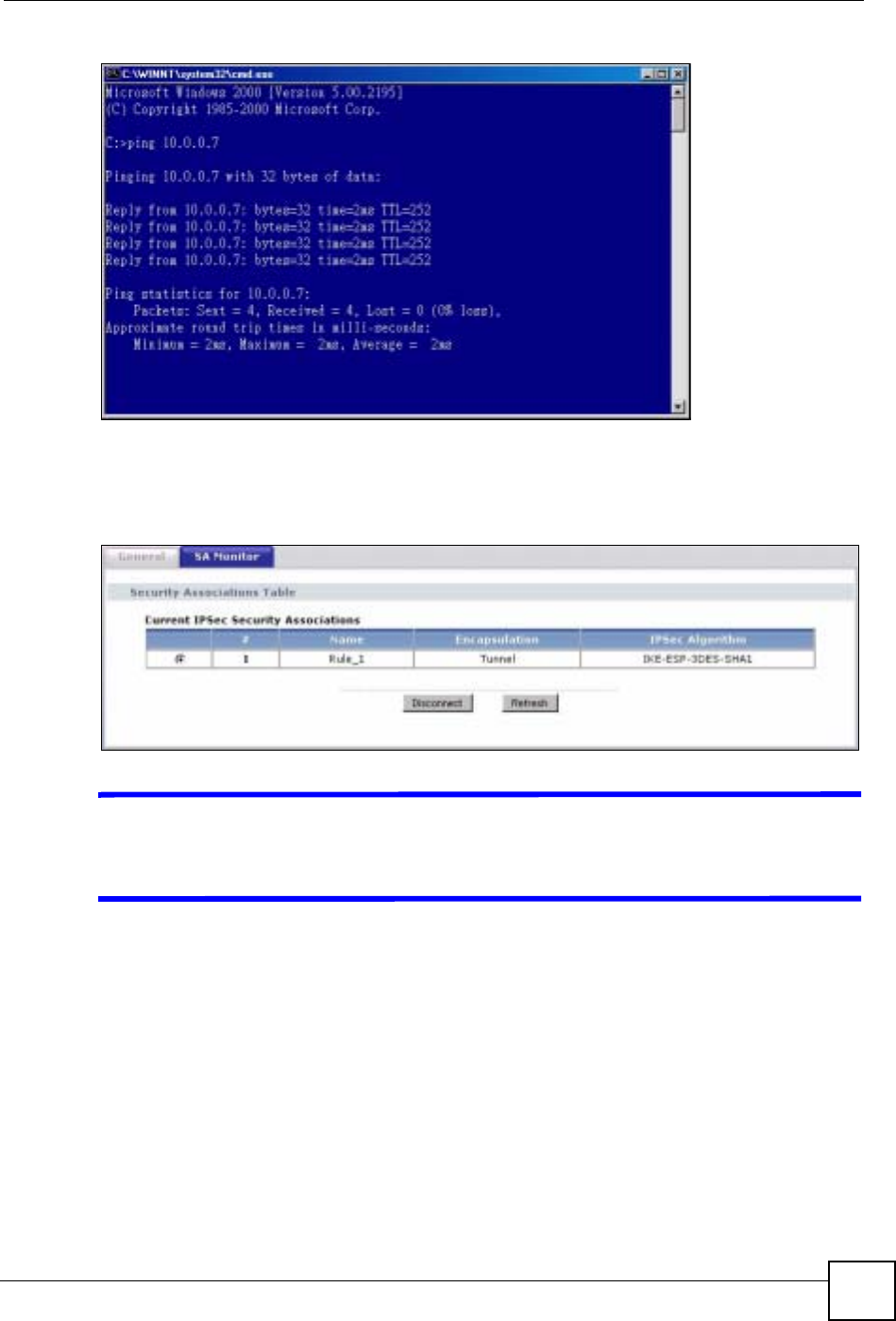
Chapter 6 Tutorials
NBG-460N User’s Guide 85
Figure 57 Pinging Jack’s Local IP Address
Pinging is successful which means a VPN tunnel has been established between Bob and Jack’s
NBG-460Ns. Congratulations! To check this VPN connection click VPN > SA Monitor in the
web configurator.
Figure 58 SA Monitor
VIf pinging is not successful check the VPN settings on both devices and try
again. If you are still having problems make sure the VPN settings in the
Advanced options are also the same.
For more information on VPN including field descriptions refer to Chapter 15 on page 165.

Chapter 6 Tutorials
NBG-460N User’s Guide
86

87
PART II
Network
Wireless LAN (89)
WAN (117)
LAN (127)
DHCP (133)
Network Address Translation (NAT) (137)
Dynamic DNS (147)

88
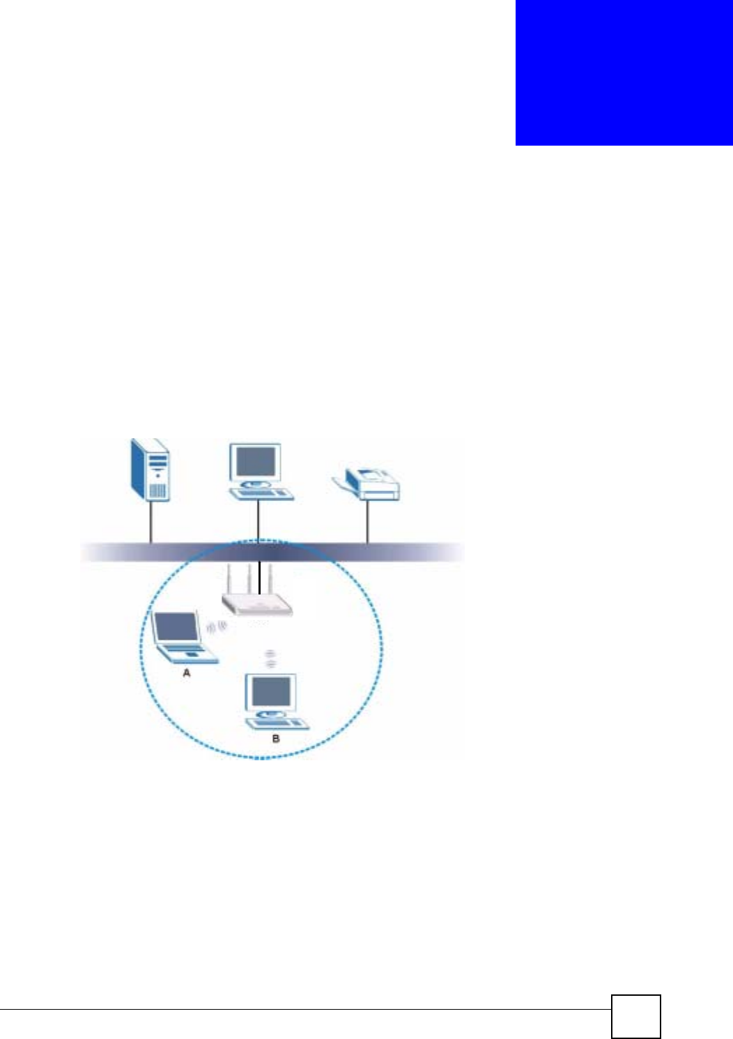
NBG-460N User’s Guide 89
CHAPTER 7
Wireless LAN
This chapter discusses how to configure the wireless network settings in your NBG-460N. See
the appendices for more detailed information about wireless networks.
7.1 Wireless Network Overview
The following figure provides an example of a wireless network.
Figure 59 Example of a Wireless Network
The wireless network is the part in the blue circle. In this wireless network, devices A and B
are called wireless clients. The wireless clients use the access point (AP) to interact with other
devices (such as the printer) or with the Internet. Your NBG-460N is the AP.
Every wireless network must follow these basic guidelines.
• Every wireless client in the same wireless network must use the same SSID.
The SSID is the name of the wireless network. It stands for Service Set IDentity.
• If two wireless networks overlap, they should use different channels.
Like radio stations or television channels, each wireless network uses a specific channel,
or frequency, to send and receive information.
AP

Chapter 7 Wireless LAN
NBG-460N User’s Guide
90
• Every wireless client in the same wireless network must use security compatible with the
AP.
Security stops unauthorized devices from using the wireless network. It can also protect
the information that is sent in the wireless network.
7.2 Wireless Security Overview
The following sections introduce different types of wireless security you can set up in the
wireless network.
7.2.1 SSID
Normally, the AP acts like a beacon and regularly broadcasts the SSID in the area. You can
hide the SSID instead, in which case the AP does not broadcast the SSID. In addition, you
should change the default SSID to something that is difficult to guess.
This type of security is fairly weak, however, because there are ways for unauthorized devices
to get the SSID. In addition, unauthorized devices can still see the information that is sent in
the wireless network.
7.2.2 MAC Address Filter
Every wireless client has a unique identification number, called a MAC address.1 A MAC
address is usually written using twelve hexadecimal characters2; for example, 00A0C5000002
or 00:A0:C5:00:00:02. To get the MAC address for each wireless client, see the appropriate
User’s Guide or other documentation.
You can use the MAC address filter to tell the AP which wireless clients are allowed or not
allowed to use the wireless network. If a wireless client is allowed to use the wireless network,
it still has to have the correct settings (SSID, channel, and security). If a wireless client is not
allowed to use the wireless network, it does not matter if it has the correct settings.
This type of security does not protect the information that is sent in the wireless network.
Furthermore, there are ways for unauthorized devices to get the MAC address of an authorized
wireless client. Then, they can use that MAC address to use the wireless network.
7.2.3 User Authentication
You can make every user log in to the wireless network before they can use it. This is called
user authentication. However, every wireless client in the wireless network has to support
IEEE 802.1x to do this.
For wireless networks, there are two typical places to store the user names and passwords for
each user.
• In the AP: this feature is called a local user database or a local database.
• In a RADIUS server: this is a server used in businesses more than in homes.
1. Some wireless devices, such as scanners, can detect wireless networks but cannot use wireless networks.
These kinds of wireless devices might not have MAC addresses.
2. Hexadecimal characters are 0, 1, 2, 3, 4, 5, 6, 7, 8, 9, A, B, C, D, E, and F.

Chapter 7 Wireless LAN
NBG-460N User’s Guide 91
If your AP does not provide a local user database and if you do not have a RADIUS server,
you cannot set up user names and passwords for your users.
Unauthorized devices can still see the information that is sent in the wireless network, even if
they cannot use the wireless network. Furthermore, there are ways for unauthorized wireless
users to get a valid user name and password. Then, they can use that user name and password
to use the wireless network.
Local user databases also have an additional limitation that is explained in the next section.
7.2.4 Encryption
Wireless networks can use encryption to protect the information that is sent in the wireless
network. Encryption is like a secret code. If you do not know the secret code, you cannot
understand the message.
The types of encryption you can choose depend on the type of user authentication. (See
Section 7.2.3 on page 90 for information about this.)
For example, if the wireless network has a RADIUS server, you can choose WPA or WPA2.
If users do not log in to the wireless network, you can choose no encryption, Static WEP,
WPA-PSK, or WPA2-PSK.
Usually, you should set up the strongest encryption that every wireless client in the wireless
network supports. For example, suppose the AP does not have a local user database, and you
do not have a RADIUS server. Therefore, there is no user authentication. Suppose the wireless
network has two wireless clients. Device A only supports WEP, and device B supports WEP
and WPA. Therefore, you should set up Static WEP in the wireless network.
"It is recommended that wireless networks use WPA-PSK,WPA, or stronger
encryption. IEEE 802.1x and WEP encryption are better than none at all, but it
is still possible for unauthorized devices to figure out the original information
pretty quickly.
It is not possible to use WPA-PSK,WPA or stronger encryption with a local
user database. In this case, it is better to set up stronger encryption with no
authentication than to set up weaker encryption with the local user database.
Table 27 Types of Encryption for Each Type of Authentication
NO AUTHENTICATION RADIUS SERVER
Weakest No Security WPA
Static WEP
WPA-PSK
Strongest WPA2-PSK WPA2

Chapter 7 Wireless LAN
NBG-460N User’s Guide
92
When you select WPA2 or WPA2-PSK in your NBG-460N, you can also select an option
(WPA Compatible) to support WPA as well. In this case, if some wireless clients support
WPA and some support WPA2, you should set up WPA2-PSK or WPA2 (depending on the
type of wireless network login) and select the WPA Compatible option in the NBG-460N.
Many types of encryption use a key to protect the information in the wireless network. The
longer the key, the stronger the encryption. Every wireless client in the wireless network must
have the same key.
7.3 Roaming
A wireless station is a device with an IEEE 802.11a/b/g/n compliant wireless interface. An
access point (AP) acts as a bridge between the wireless and wired networks. An AP creates its
own wireless coverage area. A wireless station can associate with a particular access point
only if it is within the access point’s coverage area.
In a network environment with multiple access points, wireless stations are able to switch from
one access point to another as they move between the coverage areas. This is known as
roaming. As the wireless station moves from place to place, it is responsible for choosing the
most appropriate access point depending on the signal strength, network utilization or other
factors.
The roaming feature on the access points allows the access points to relay information about
the wireless stations to each other. When a wireless station moves from a coverage area to
another, it scans and uses the channel of a new access point, which then informs the other
access points on the LAN about the change. An example is shown in Figure 60 on page 93.
With roaming, a wireless LAN mobile user enjoys a continuous connection to the wired
network through an access point while moving around the wireless LAN.
Enable roaming to exchange the latest bridge information of all wireless stations between APs
when a wireless station moves between coverage areas. Wireless stations can still associate
with other APs even if you disable roaming. Enabling roaming ensures correct traffic
forwarding (bridge tables are updated) and maximum AP efficiency. The AP deletes records
of wireless stations that associate with other APs (Non-ZyXEL APs may not be able to
perform this). 802.1x authentication information is not exchanged (at the time of writing).
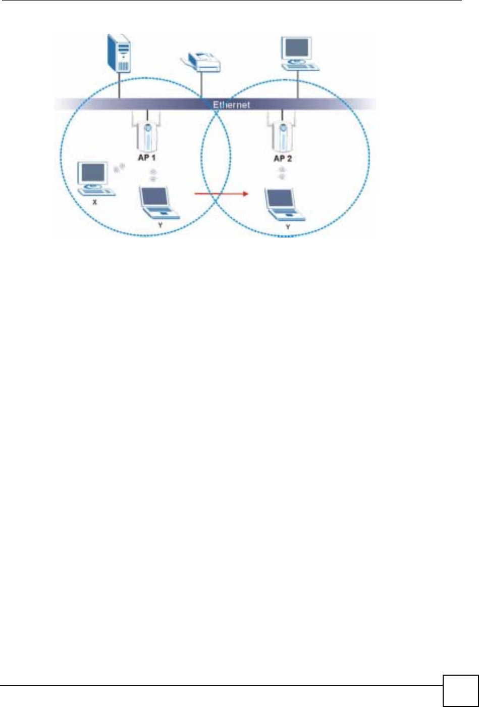
Chapter 7 Wireless LAN
NBG-460N User’s Guide 93
Figure 60 Roaming Example
The steps below describe the roaming process.
1Wireless station Y moves from the coverage area of access point AP 1 to that of access
point AP 2.
2Wireless station Y scans and detects the signal of access point AP 2.
3Wireless station Y sends an association request to access point AP 2.
4Access point AP 2 acknowledges the presence of wireless station Y and relays this
information to access point AP 1 through the wired LAN.
5Access point AP 1 updates the new position of wireless station Y.
7.3.1 Requirements for Roaming
The following requirements must be met in order for wireless stations to roam between the
coverage areas.
1All the access points must be on the same subnet and configured with the same ESSID.
2If IEEE 802.1x user authentication is enabled and to be done locally on the access point,
the new access point must have the user profile for the wireless station.
3The adjacent access points should use different radio channels when their coverage areas
overlap.
4All access points must use the same port number to relay roaming information.
5The access points must be connected to the Ethernet and be able to get IP addresses from
a DHCP server if using dynamic IP address assignment.
7.4 Quality of Service
This section discusses the Quality of Service (QoS) features available on the NBG-460N.

Chapter 7 Wireless LAN
NBG-460N User’s Guide
94
7.4.1 WMM QoS
WMM (Wi-Fi MultiMedia) QoS (Quality of Service) ensures quality of service in wireless
networks. It controls WLAN transmission priority on packets to be transmitted over the
wireless network.
WMM QoS prioritizes wireless traffic according to delivery requirements. WMM QoS is a
part of the IEEE 802.11e QoS enhancement to certified Wi-Fi wireless networks.
On APs without WMM QoS, all traffic streams are given the same access priority to the
wireless network. If the introduction of another traffic stream creates a data transmission
demand that exceeds the current network capacity, then the new traffic stream reduces the
throughput of the other traffic streams.
The NBG-460N uses WMM QoS to prioritize traffic streams according to the IEEE 802.1q tag
or DSCP information in each packet’s header. The NBG-460N automatically determines the
priority to use for an individual traffic stream. This prevents reductions in data transmission
for applications that are sensitive to latency (delay) and jitter (variations in delay).
7.4.1.1 WMM QoS Priorities
The following table describes the WMM QoS priority levels that the NBG-460N uses.
7.5 General Wireless LAN Screen
"If you are configuring the NBG-460N from a computer connected to the
wireless LAN and you change the NBG-460N’s SSID, channel or security
settings, you will lose your wireless connection when you press Apply to
confirm. You must then change the wireless settings of your computer to
match the NBG-460N’s new settings.
Click Network > Wireless LAN to open the General screen.
Table 28 WMM QoS Priorities
PRIORITY LEVEL DESCRIPTION
voice
(WMM_VOICE)
Typically used for traffic that is especially sensitive to jitter. Use this priority
to reduce latency for improved voice quality.
video
(WMM_VIDEO)
Typically used for traffic which has some tolerance for jitter but needs to be
prioritized over other data traffic.
best effort
(WMM_BEST_EFFORT)
Typically used for traffic from applications or devices that lack QoS
capabilities. Use best effort priority for traffic that is less sensitive to latency,
but is affected by long delays, such as Internet surfing.
background
(WMM_BACKGROUND)
This is typically used for non-critical traffic such as bulk transfers and print
jobs that are allowed but that should not affect other applications and users.
Use background priority for applications that do not have strict latency and
throughput requirements.
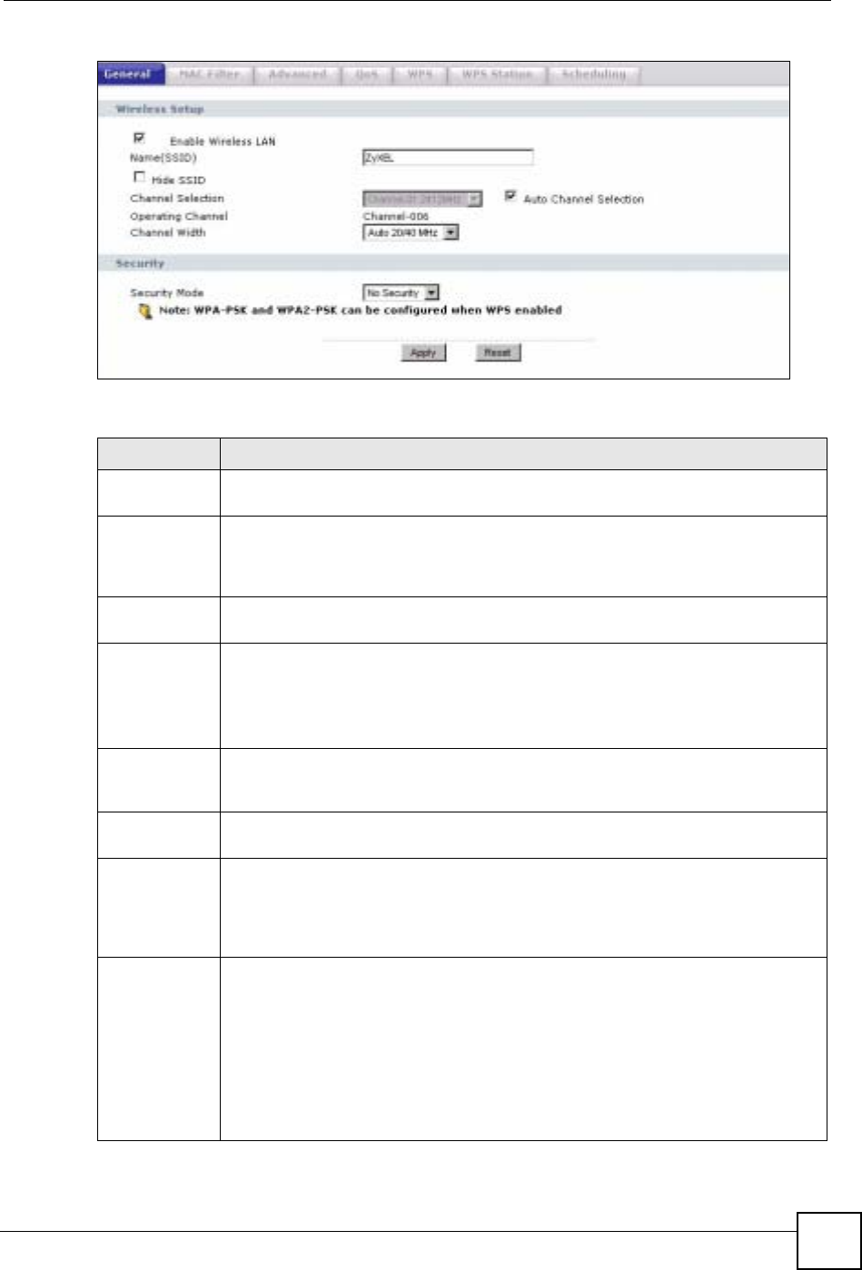
Chapter 7 Wireless LAN
NBG-460N User’s Guide 95
Figure 61 Network > Wireless LAN > General
The following table describes the general wireless LAN labels in this screen.
Table 29 Network > Wireless LAN > General
LABEL DESCRIPTION
Enable
Wireless LAN Click the check box to activate wireless LAN.
Name(SSID) (Service Set IDentity) The SSID identifies the Service Set with which a wireless
station is associated. Wireless stations associating to the access point (AP) must
have the same SSID. Enter a descriptive name (up to 32 printable 7-bit ASCII
characters) for the wireless LAN.
Hide SSID Select this check box to hide the SSID in the outgoing beacon frame so a station
cannot obtain the SSID through scanning using a site survey tool.
Channel
Selection Set the operating frequency/channel depending on your particular region.
Select a channel from the drop-down list box. The options vary depending on the
frequency band and the country you are in.
Refer to the Connection Wizard chapter for more information on channels. This
option is only available if Auto Channel Selection is disabled.
Auto Channel
Selection Select this check box for the NBG-460N to automatically choose the channel with the
least interference. Deselect this check box if you wish to manually select the channel
using the Channel Section field.
Operating
Channel This displays the channel the NBG-460N is currently using.
Channel Width Select whether the NBG-460N uses a wireless channel width of 20 or 40 MHz. A
standard 20 MHz channel offers transfer speeds of up to 150Mbps whereas a
40MHz channel uses two standard channels and offers speeds of up to 300 Mbps.
Because not all devices support 40 MHz channels, select Auto 20/40MHz to allow
the NBG-460N to adjust the channel bandwidth automatically.
Security Mode Select Static-WEP,WPA-PSK,WPA,WPA2-PSK, or WPA2 to add security on this
wireless network. The wireless clients which want to associate to this network must
have same wireless security settings as this device. After you select to use a
security, additional options appears in this screen. See 7.5.2,7.5.3,7.5.4 sections.
Or you can select No Security to allow any client to associate this network without
authentication.
Note: If you enable the WPS function, only No Security,WPA-PSK
and WPA2-PSK are available in this field.
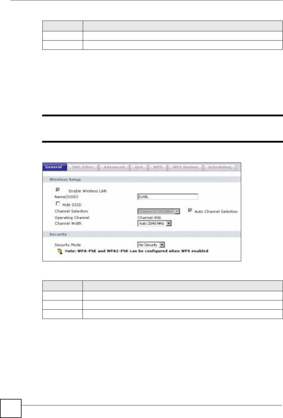
Chapter 7 Wireless LAN
NBG-460N User’s Guide
96
See the rest of this chapter for information on the other labels in this screen.
7.5.1 No Security
Select No Security to allow wireless stations to communicate with the access points without
any data encryption.
"If you do not enable any wireless security on your NBG-460N, your network is
accessible to any wireless networking device that is within range.
Figure 62 Network > Wireless LAN > General: No Security
The following table describes the labels in this screen.
7.5.2 WEP Encryption
WEP encryption scrambles the data transmitted between the wireless stations and the access
points to keep network communications private. It encrypts unicast and multicast
communications in a network. Both the wireless stations and the access points must use the
same WEP key.
Apply Click Apply to save your changes back to the NBG-460N.
Reset Click Reset to reload the previous configuration for this screen.
Table 29 Network > Wireless LAN > General
LABEL DESCRIPTION
Table 30 Wireless No Security
LABEL DESCRIPTION
Security Mode Choose No Security from the drop-down list box.
Apply Click Apply to save your changes back to the NBG-460N.
Reset Click Reset to reload the previous configuration for this screen.
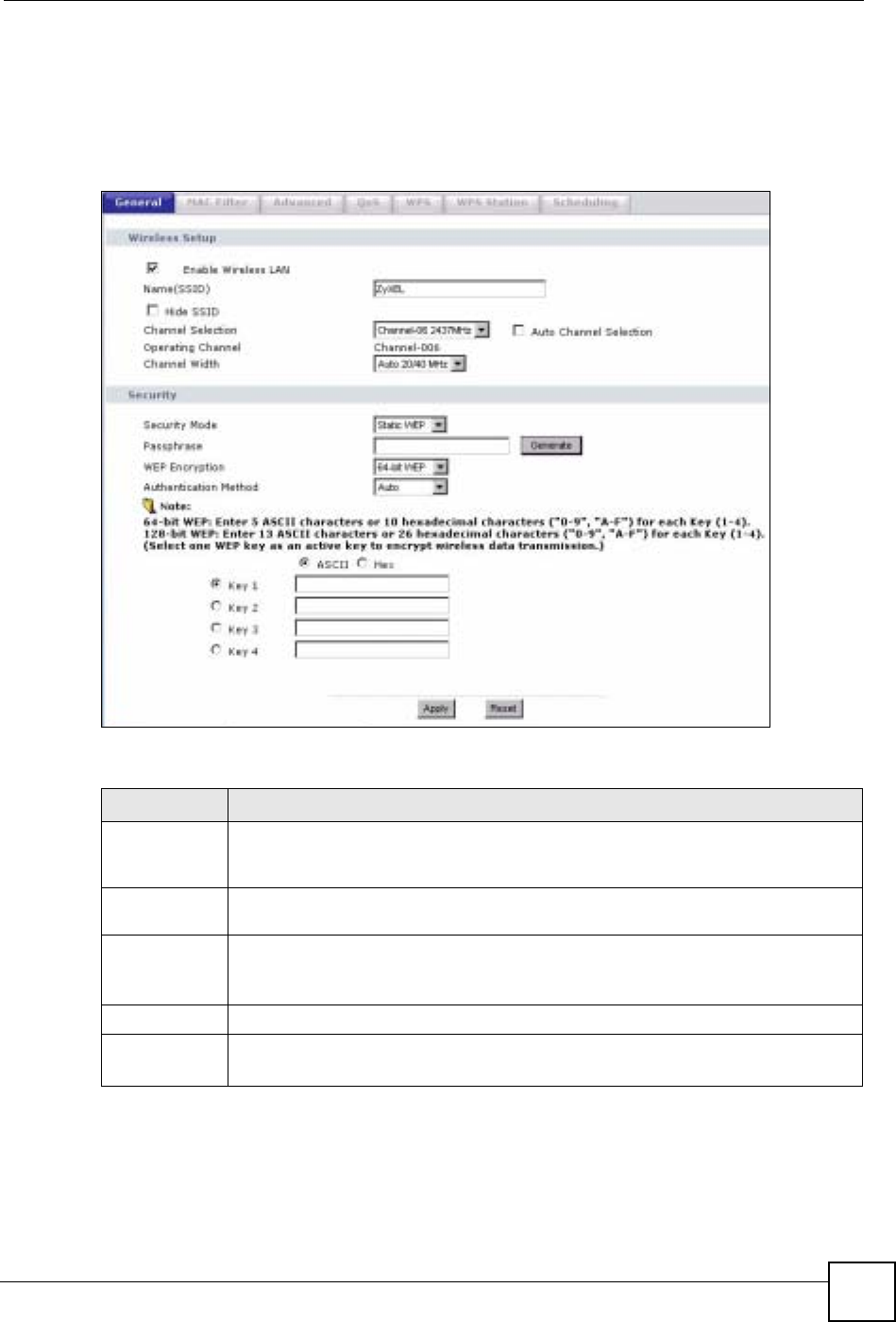
Chapter 7 Wireless LAN
NBG-460N User’s Guide 97
Your NBG-460N allows you to configure up to four 64-bit or 128-bit WEP keys but only one
key can be enabled at any one time.
In order to configure and enable WEP encryption; click Network > Wireless LAN to display
the General screen. Select Static WEP from the Security Mode list.
Figure 63 Network > Wireless LAN > General: Static WEP
The following table describes the wireless LAN security labels in this screen.
Table 31 Network > Wireless LAN > General: Static WEP
LABEL DESCRIPTION
Passphrase Enter a passphrase (password phrase) of up to 32 printable characters and click
Generate. The NBG-460N automatically generates four different WEP keys and
displays them in the Key fields below.
WEP
Encryption Select 64-bit WEP or 128-bit WEP to enable data encryption.
Authentication
Method This field is activated when you select 64-bit WEP or 128-bit WEP in the WEP
Encryption field.
Select Auto or Shared Key from the drop-down list box.
ASCII Select this option in order to enter ASCII characters as WEP key.
Hex Select this option in order to enter hexadecimal characters as a WEP key.
The preceding "0x", that identifies a hexadecimal key, is entered automatically.
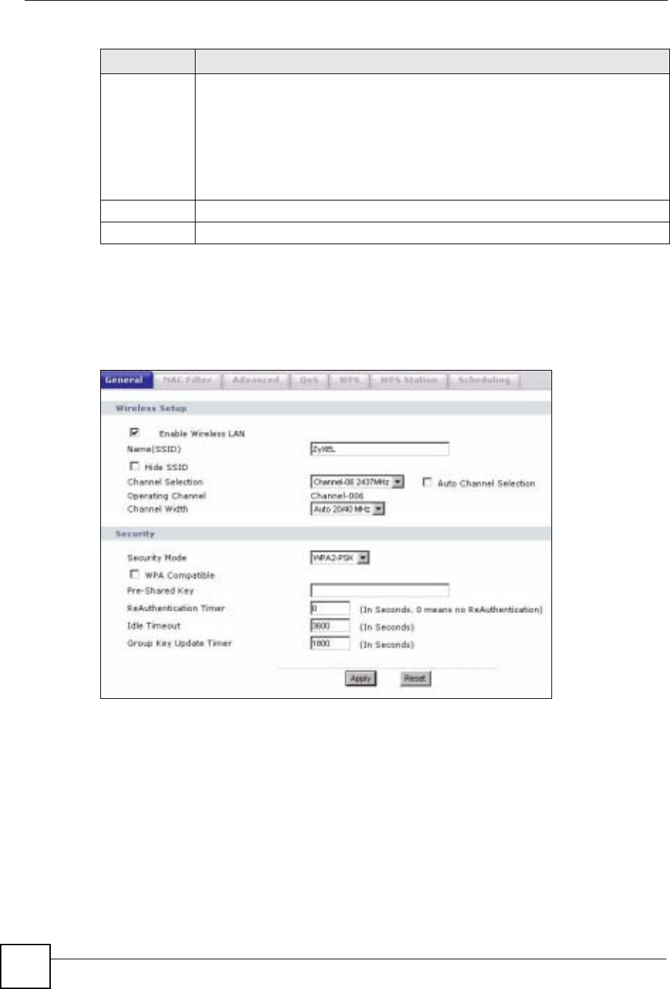
Chapter 7 Wireless LAN
NBG-460N User’s Guide
98
7.5.3 WPA-PSK/WPA2-PSK
Click Network > Wireless LAN to display the General screen. Select WPA-PSK or WPA2-
PSK from the Security Mode list.
Figure 64 Network > Wireless LAN > General: WPA-PSK/WPA2-PSK
Key 1 to Key 4 The WEP keys are used to encrypt data. Both the NBG-460N and the wireless
stations must use the same WEP key for data transmission.
If you chose 64-bit WEP, then enter any 5 ASCII characters or 10 hexadecimal
characters ("0-9", "A-F").
If you chose 128-bit WEP, then enter 13 ASCII characters or 26 hexadecimal
characters ("0-9", "A-F").
You must configure at least one key, only one key can be activated at any one time.
The default key is key 1.
Apply Click Apply to save your changes back to the NBG-460N.
Reset Click Reset to reload the previous configuration for this screen.
Table 31 Network > Wireless LAN > General: Static WEP
LABEL DESCRIPTION

Chapter 7 Wireless LAN
NBG-460N User’s Guide 99
The following table describes the labels in this screen.
7.5.4 WPA/WPA2
Click Network > Wireless LAN to display the General screen. Select WPA or WPA2 from
the Security Mode list.
Table 32 Network > Wireless LAN > General: WPA-PSK/WPA2-PSK
LABEL DESCRIPTION
WPA Compatible This check box is available only when you select WPA2-PSK or WPA2 in the
Security Mode field.
Select the check box to have both WPA2 and WPA wireless clients be able to
communicate with the NBG-460N even when the NBG-460N is using WPA2-PSK
or WPA2.
Pre-Shared Key The encryption mechanisms used for WPA/WPA2 and WPA-PSK/WPA2-PSK
are the same. The only difference between the two is that WPA-PSK/WPA2-PSK
uses a simple common password, instead of user-specific credentials.
Type a pre-shared key from 8 to 63 case-sensitive ASCII characters (including
spaces and symbols).
ReAuthentication
Timer (in
seconds)
Specify how often wireless stations have to resend usernames and passwords in
order to stay connected. Enter a time interval between 10 and 9999 seconds. The
default time interval is 1800 seconds (30 minutes).
Note: If wireless station authentication is done using a RADIUS
server, the reauthentication timer on the RADIUS server has
priority.
Idle Timeout The NBG-460N automatically disconnects a wireless station from the wired
network after a period of inactivity. The wireless station needs to enter the
username and password again before access to the wired network is allowed. The
default time interval is 3600 seconds (or 1 hour).
Group Key
Update Timer The Group Key Update Timer is the rate at which the AP (if using WPA-PSK/
WPA2-PSK key management) or RADIUS server (if using WPA/WPA2 key
management) sends a new group key out to all clients. The re-keying process is
the WPA/WPA2 equivalent of automatically changing the WEP key for an AP and
all stations in a WLAN on a periodic basis. Setting of the Group Key Update
Timer is also supported in WPA-PSK/WPA2-PSK mode. The default is 1800
seconds (30 minutes).
Apply Click Apply to save your changes back to the NBG-460N.
Reset Click Reset to reload the previous configuration for this screen.
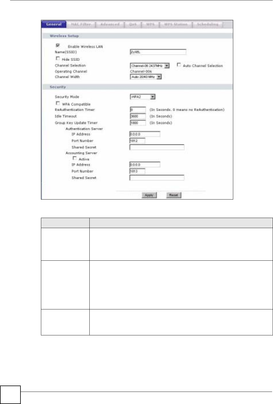
Chapter 7 Wireless LAN
NBG-460N User’s Guide
100
Figure 65 Network > Wireless LAN > General: WPA/WPA2
The following table describes the labels in this screen.
Table 33 Network > Wireless LAN > General: WPA/WPA2
LABEL DESCRIPTION
WPA Compatible This check box is available only when you select WPA2-PSK or WPA2 in the
Security Mode field.
Select the check box to have both WPA2 and WPA wireless clients be able to
communicate with the NBG-460N even when the NBG-460N is using WPA2-
PSK or WPA2.
ReAuthentication
Timer (in seconds) Specify how often wireless stations have to resend usernames and passwords in
order to stay connected. Enter a time interval between 10 and 9999 seconds.
The default time interval is 1800 seconds (30 minutes).
Note: If wireless station authentication is done using a RADIUS
server, the reauthentication timer on the RADIUS server
has priority.
Idle Timeout The NBG-460N automatically disconnects a wireless station from the wired
network after a period of inactivity. The wireless station needs to enter the
username and password again before access to the wired network is allowed.
The default time interval is 3600 seconds (or 1 hour).

Chapter 7 Wireless LAN
NBG-460N User’s Guide 101
7.6 MAC Filter
The MAC filter screen allows you to configure the NBG-460N to give exclusive access to up
to 32 devices (Allow) or exclude up to 32 devices from accessing the NBG-460N (Deny).
Every Ethernet device has a unique MAC (Media Access Control) address. The MAC address
is assigned at the factory and consists of six pairs of hexadecimal characters, for example,
00:A0:C5:00:00:02. You need to know the MAC address of the devices to configure this
screen.
To change your NBG-460N’s MAC filter settings, click Network > Wireless LAN > MAC
Filter. The screen appears as shown.
Group Key Update
Timer The Group Key Update Timer is the rate at which the AP (if using WPA-PSK/
WPA2-PSK key management) or RADIUS server (if using WPA/WPA2 key
management) sends a new group key out to all clients. The re-keying process is
the WPA/WPA2 equivalent of automatically changing the WEP key for an AP
and all stations in a WLAN on a periodic basis. Setting of the Group Key Update
Timer is also supported in WPA-PSK/WPA2-PSK mode. The NBG-460N default
is 1800 seconds (30 minutes).
Authentication Server
IP Address Enter the IP address of the external authentication server in dotted decimal
notation.
Port Number Enter the port number of the external authentication server. The default port
number is 1812.
You need not change this value unless your network administrator instructs you
to do so with additional information.
Shared Secret Enter a password (up to 31 alphanumeric characters) as the key to be shared
between the external authentication server and the NBG-460N.
The key must be the same on the external authentication server and your NBG-
460N. The key is not sent over the network.
Accounting Server
Active Select Yes from the drop down list box to enable user accounting through an
external authentication server.
IP Address Enter the IP address of the external accounting server in dotted decimal notation.
Port Number Enter the port number of the external accounting server. The default port number
is 1813.
You need not change this value unless your network administrator instructs you
to do so with additional information.
Shared Secret Enter a password (up to 31 alphanumeric characters) as the key to be shared
between the external accounting server and the NBG-460N.
The key must be the same on the external accounting server and your NBG-
460N. The key is not sent over the network.
Apply Click Apply to save your changes back to the NBG-460N.
Reset Click Reset to reload the previous configuration for this screen.
Table 33 Network > Wireless LAN > General: WPA/WPA2
LABEL DESCRIPTION
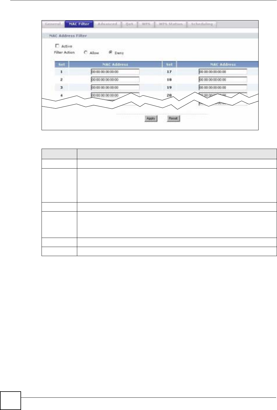
Chapter 7 Wireless LAN
NBG-460N User’s Guide
102
Figure 66 Network > Wireless LAN > MAC Filter
The following table describes the labels in this menu.
7.7 Wireless LAN Advanced Screen
Click Network > Wireless LAN > Advanced. The screen appears as shown.
Table 34 Network > Wireless LAN > MAC Filter
LABEL DESCRIPTION
Active Select Yes from the drop down list box to enable MAC address filtering.
Filter Action Define the filter action for the list of MAC addresses in the MAC Address table.
Select Deny to block access to the NBG-460N, MAC addresses not listed will be
allowed to access the NBG-460N
Select Allow to permit access to the NBG-460N, MAC addresses not listed will be
denied access to the NBG-460N.
Set This is the index number of the MAC address.
MAC
Address Enter the MAC addresses of the wireless station that are allowed or denied access to
the NBG-460N in these address fields. Enter the MAC addresses in a valid MAC
address format, that is, six hexadecimal character pairs, for example,
12:34:56:78:9a:bc.
Apply Click Apply to save your changes back to the NBG-460N.
Reset Click Reset to reload the previous configuration for this screen.
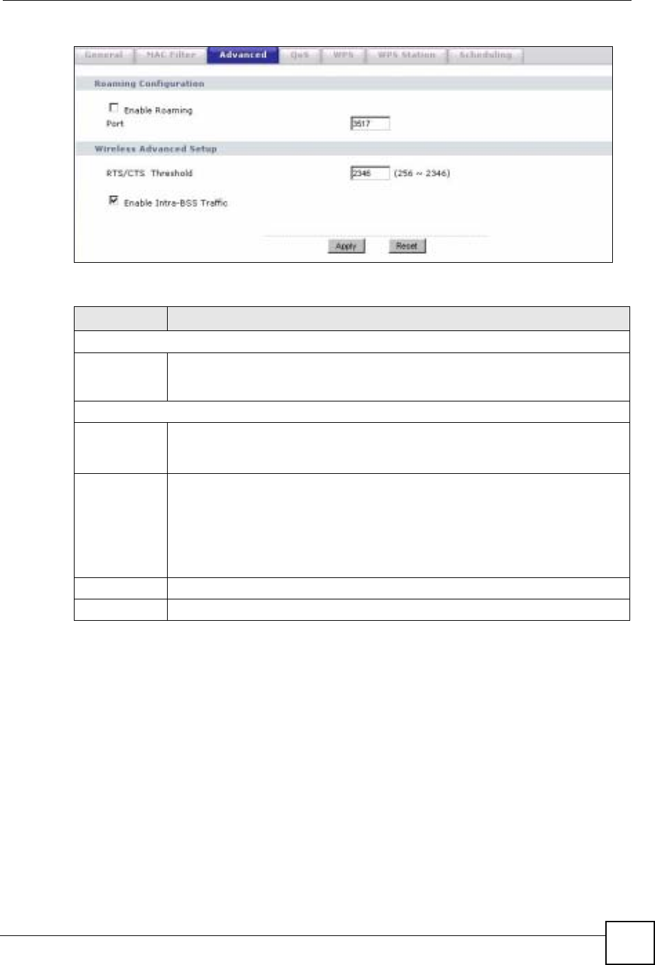
Chapter 7 Wireless LAN
NBG-460N User’s Guide 103
Figure 67 Network > Wireless LAN > Advanced
The following table describes the labels in this screen.
7.8 Quality of Service (QoS) Screen
The QoS screen allows you to automatically give a service (such as e-mail, VoIP or FTP) a
priority level.
Click Network > Wireless LAN > QoS. The following screen appears.
Table 35 Network > Wireless LAN > Advanced
LABEL DESCRIPTION
Roaming Configuration
Enable
Roaming Select this option if your network environment has multiple APs and you want your
wireless device to be able to access the network as you move between wireless
networks.
Wireless Advanced Setup
RTS/CTS
Threshold Data with its frame size larger than this value will perform the RTS (Request To
Send)/CTS (Clear To Send) handshake.
Enter a value between 0 and 2432.
Enable Intra-
BSS Traffic A Basic Service Set (BSS) exists when all communications between wireless clients
or between a wireless client and a wired network client go through one access point
(AP).
Intra-BSS traffic is traffic between wireless clients in the BSS. When Intra-BSS is
enabled, wireless client A and B can access the wired network and communicate
with each other. When Intra-BSS is disabled, wireless client A and B can still access
the wired network but cannot communicate with each other.
Apply Click Apply to save your changes back to the NBG-460N.
Reset Click Reset to reload the previous configuration for this screen.
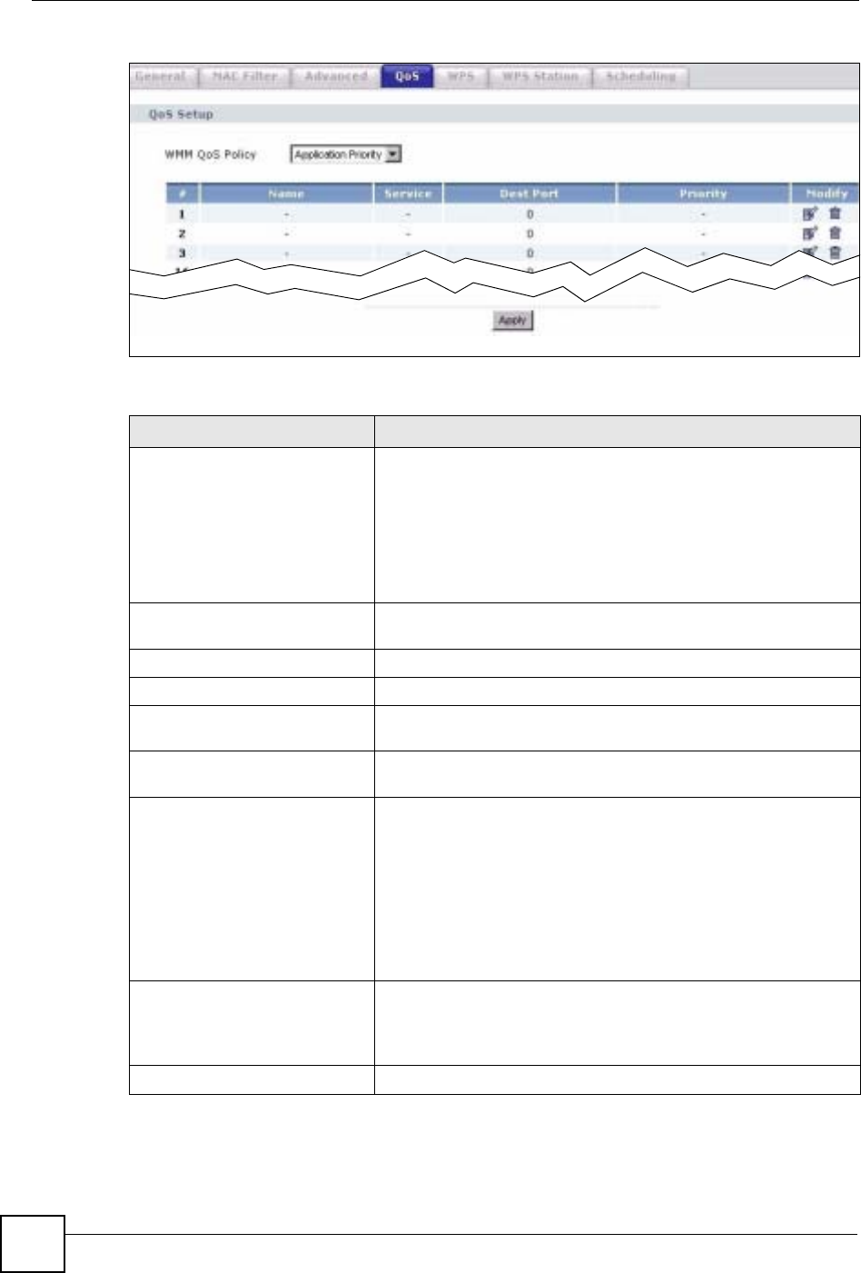
Chapter 7 Wireless LAN
NBG-460N User’s Guide
104
Figure 68 Network > Wireless LAN > QoS
The following table describes the labels in this screen.
Table 36 Network > Wireless LAN > QoS
LABEL DESCRIPTION
WMM QoS Policy Select Default to have the NBG-460N automatically give a service
a priority level according to the ToS value in the IP header of
packets it sends. WMM QoS (Wifi MultiMedia Quality of Service)
gives high priority to voice and video, which makes them run more
smoothly.
Select Application Priority from the drop-down list box to display a
table of application names, services, ports and priorities to which
you want to apply WMM QoS.
The table appears only if you select Application Priority in WMM
QoS Policy.
# This is the number of an individual application entry.
Name This field displays a description given to an application entry.
Service This field displays either FTP,WWW,E-mail or a User Defined
service to which you want to apply WMM QoS.
Dest Port This field displays the destination port number to which the
application sends traffic.
Priority This field displays the priority of the application.
Highest - Typically used for voice or video that should be high-
quality.
High - Typically used for voice or video that can be medium-quality.
Mid - Typically used for applications that do not fit into another
priority. For example, Internet surfing.
Low - Typically used for non-critical “background” applications,
such as large file transfers and print jobs that should not affect
other applications.
Modify Click the Edit icon to open the Application Priority Configuration
screen. Modify an existing application entry or create a application
entry in the Application Priority Configuration screen.
Click the Remove icon to delete an application entry.
Apply Click Apply to save your changes to the NBG-460N.
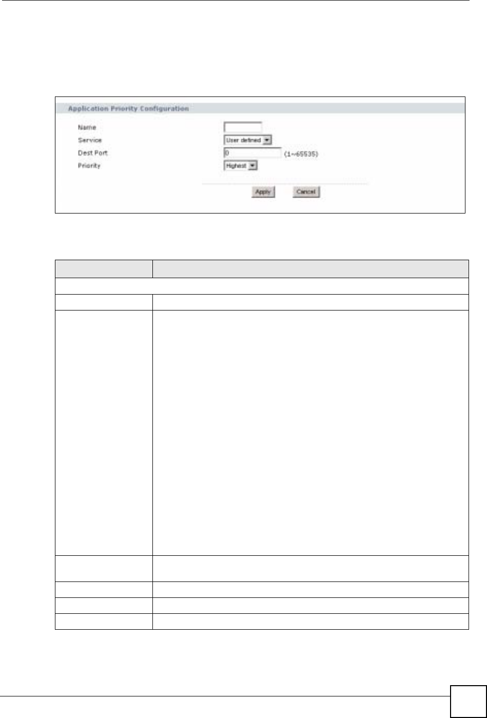
Chapter 7 Wireless LAN
NBG-460N User’s Guide 105
7.8.1 Application Priority Configuration
Use this screen to edit a WMM QoS application entry. Click the edit icon under Modify. The
following screen displays.
Figure 69 Network > Wireless LAN > QoS: Application Priority Configuration
See Appendix F on page 321 for a list of commonly-used services and destination ports. The
following table describes the fields in this screen.
Network > Wireless LAN > QoS: Application Priority Configuration
LABEL DESCRIPTION
Application Priority Configuration
Name Type a description of the application priority.
Service The following is a description of the applications you can prioritize with WMM
QoS. Select a service from the drop-down list box.
• E-Mail
Electronic mail consists of messages sent through a computer network to
specific groups or individuals. Here are some default ports for e-mail:
POP3 - port 110
IMAP - port 143
SMTP - port 25
HTTP - port 80
•FTP
File Transfer Protocol enables fast transfer of files, including large files that it
may not be possible to send via e-mail. FTP uses port number 21.
•WWW
The World Wide Web is an Internet system to distribute graphical, hyper-
linked information, based on Hyper Text Transfer Protocol (HTTP) - a client/
server protocol for the World Wide Web. The Web is not synonymous with the
Internet; rather, it is just one service on the Internet. Other services on the
Internet include Internet Relay Chat and Newsgroups. The Web is accessed
through use of a browser.
•User-Defined
User-defined services are user specific services configured using known ports
and applications.
Dest Port This displays the port the selected service uses. Type a port number in the
field provided if you want to use a different port to the default port.
Priority Select a priority from the drop-down list box.
Apply Click Apply to save your changes back to the NBG-460N.
Cancel Click Cancel to return to the previous screen.
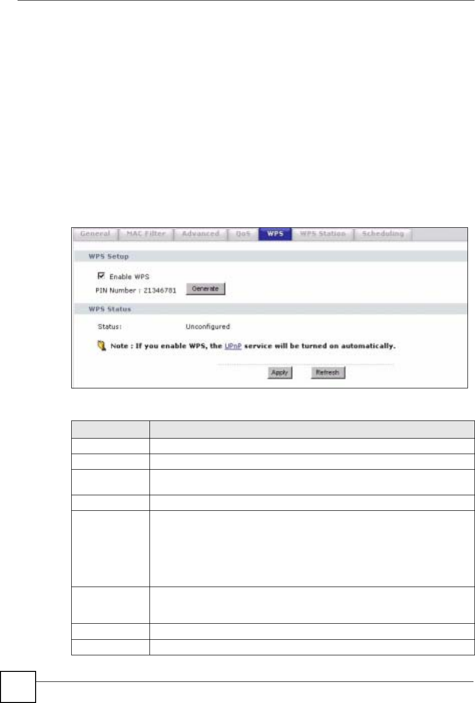
Chapter 7 Wireless LAN
NBG-460N User’s Guide
106
7.9 WiFi Protected Setup
WiFi Protected Setup (WPS) is an industry standard specification, defined by the WiFi
Alliance. WPS allows you to quickly set up a wireless network with strong security, without
having to configure security settings manually. Depending on the devices in your network,
you can either press a button (on the device itself, or in its configuration utility) or enter a PIN
(Personal Identification Number) in the devices. Then, they connect and set up a secure
network by themselves. See how to set up a secure wireless network using WPS in the Section
6.1.2 on page 73.
7.9.1 WPS Screen
Use this screen to enable/disable WPS, view or generate a new PIN number and check current
WPS status. To open this screen, click Network >Wireless LAN > WPS tab.
Figure 70 WPS
The following table describes the labels in this screen.
Table 37 WPS
LABEL DESCRIPTION
WPS Setup
Enable WPS Select this to enable the WPS feature.
PIN Number This displays a PIN number last time system generated. Click Generate to
generate a new PIN number.
WPS Status
Status This displays Configured when the NBG-460N has connected to a wireless
network using WPS or when Enable WPS is selected and wireless or wireless
security settings have been changed. The current wireless and wireless security
settings also appear in the screen.
This displays Unconfigured if WPS is disabled and there are no wireless or
wireless security changes on the NBG-460N or you click Release_Configuration
to remove the configured wireless and wireless security settings.
Release
Configuration This button is only available when the WPS status displays Configured.
Click this button to remove all configured wireless and wireless security settings
for WPS connections on the NBG-460N.
Apply Click Apply to save your changes back to the NBG-460N.
Refresh Click Refresh to get this screen information afresh.
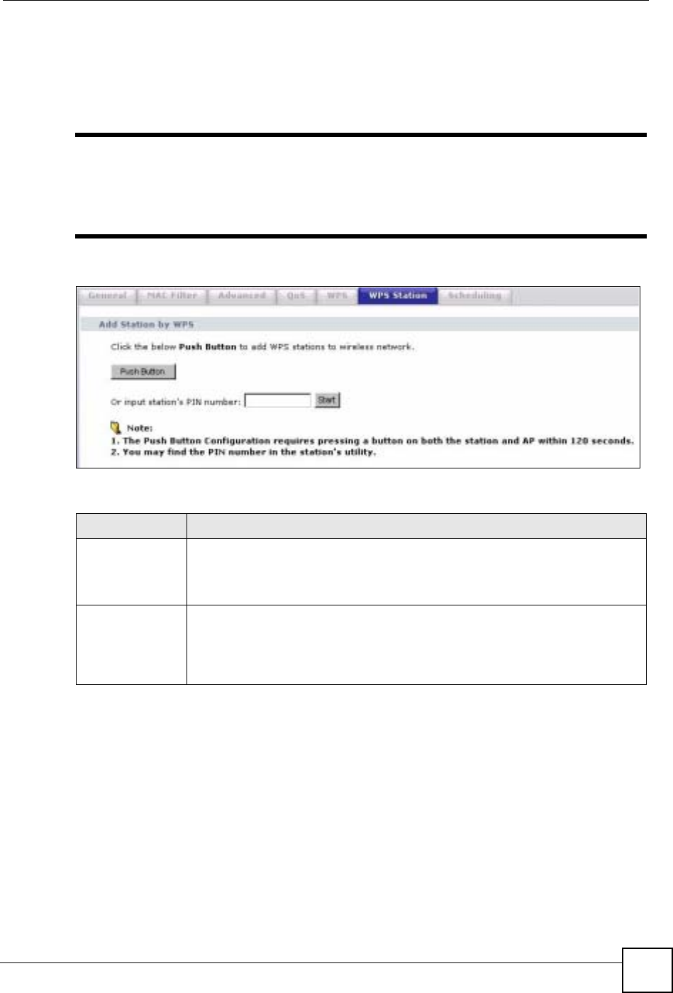
Chapter 7 Wireless LAN
NBG-460N User’s Guide 107
7.9.2 WPS Station Screen
Use this screen when you want to add a wireless station using WPS. To open this screen, click
Network > Wireless LAN > WPS Station tab.
"Note: After you click Push Button on this screen, you have to press a similar
button in the wireless station utility within 2 minutes. To add the second
wireless station, you have to press these buttons on both device and the
wireless station again after the first 2 minutes.
Figure 71 WPS Station
The following table describes the labels in this screen.
7.9.3 Scheduling
Use this screen to set the times your wireless LAN is turned on and off. Wireless LAN
scheduling is disabled by default. The wireless LAN can be scheduled to turn on or off on
certain days and at certain times. To open this screen, click Network > Wireless LAN >
Scheduling tab.
Table 38 WPS Station
LABEL DESCRIPTION
Push Button Use this button when you use the PBC (Push Button Configuration) method to
configure wireless stations’s wireless settings. See Section 6.1.2.1 on page 74.
Click this to start WPS-aware wireless station scanning and the wireless security
information synchronization.
Or input station’s
PIN number Use this button when you use the PIN Configuration method to configure wireless
station’s wireless settings. See Section 6.1.2.2 on page 75.
Type the same PIN number generated in the wireless station’s utility. Then click
Start to associate to each other and perform the wireless security information
synchronization.
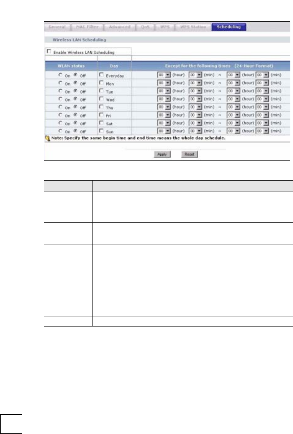
Chapter 7 Wireless LAN
NBG-460N User’s Guide
108
Figure 72 Scheduling
The following table describes the labels in this screen.
7.10 iPod Touch Web Configurator
The iPod Touch web configurator displays when you are connecting to the NBG-460N
wirelessly with an iPod Touch device through a web browser. It is different to the web
configurator that you access from your computer.
To connect wirelessly to the iPod Touch web configurator with your iPod Touch follow the
steps below:
Table 39 Scheduling
LABEL DESCRIPTION
Enable Wireless
LAN Scheduling Select this to enable Wireless LAN scheduling.
WLAN Status Select On or Off to specify whether the Wireless LAN is turned on or off. This field
works in conjunction with the Day and Except for the following times fields.
Day Select Everyday or the specific days to turn the Wireless LAN on or off. If you
select Everyday you can not select any specific days. This field works in
conjunction with the Except for the following times field.
Except for the
following times
(24-Hour Format)
Select a begin time using the first set of hour and minute (min) drop down boxes
and select an end time using the second set of hour and minute (min) drop down
boxes. If you have chosen On earlier for the WLAN Status the Wireless LAN will
turn off between the two times you enter in these fields. If you have chosen Off
earlier for the WLAN Status the Wireless LAN will turn on between the two times
you enter in these fields.
Note: Entering the same begin time and end time will mean the
whole day.
Apply Click Apply to save your changes back to the NBG-460N.
Reset Click Reset to reload the previous configuration for this screen.
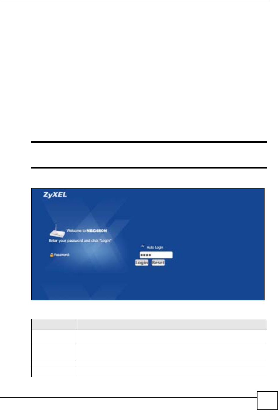
Chapter 7 Wireless LAN
NBG-460N User’s Guide 109
1Make sure the Wireless LAN on the NBG-460N is enabled and that you know the
security settings (if any). To do this check the Wireless LAN > General screen in the
web configurator from your computer.
2On the iPod Touch’s main screen press Settings > Wi-fi and from the list press the
NBG-460N’s network name (SSID) to connect to it. If you are prompted for any security
settings enter them and press connect. If you cannot connect check your security settings
in the web configurator from your computer and try again.
3After connecting to the NBG-460N’s wireless LAN network launch the iPod Touch
Internet browser and enter the NBG-460N’s IP address (default: 192.168.1.1) into the
address bar. The login screen displays.
7.10.1 Login Screen
After accessing the NBG-460N’s IP address in the iPod Touch web browser the screen below
will display.
"You cannot change your password in the iPod Touch web configurator. To
change your password log into the web configurator using your computer.
Figure 73 Login Screen
The following table describes the labels in this screen.
Table 40 Login Screen
LABEL DESCRIPTION
Auto Login Select this checkbox to automatically log into the iPod Touch web configurator
when accessing it through the same iPod Touch device.
Password Enter the password for the NBG-460N. If you haven’t changed the default
password earlier this is “1234”.
Login Press the Login button to log into the iPod Touch web configurator.
Reset Press the Reset button to clear your selections and start over.

Chapter 7 Wireless LAN
NBG-460N User’s Guide
110
7.10.2 System Status
After successfully logging into the iPod Touch web configurator the System Status screen
displays.
"Your changes in the iPod Touch web configurator are saved automatically
after pressing a button.
If you are going to use the WPS (Wi-Fi Protected Setup) function in the iPod Touch Web
Configurator it is recommended to configure your WPS settings first from your computer.
If WPS has not been configured previously the iPod Touch will lose it’s wireless connection to
the NBG-460N after the NBG-460N has connected to another device using WPS through the
iPod Touch web configurator. To reconnect to the wireless network using your iPod Touch
you must find out the new WPS settings by logging into the web configurator from your
computer and going to the Wireless LAN screen.
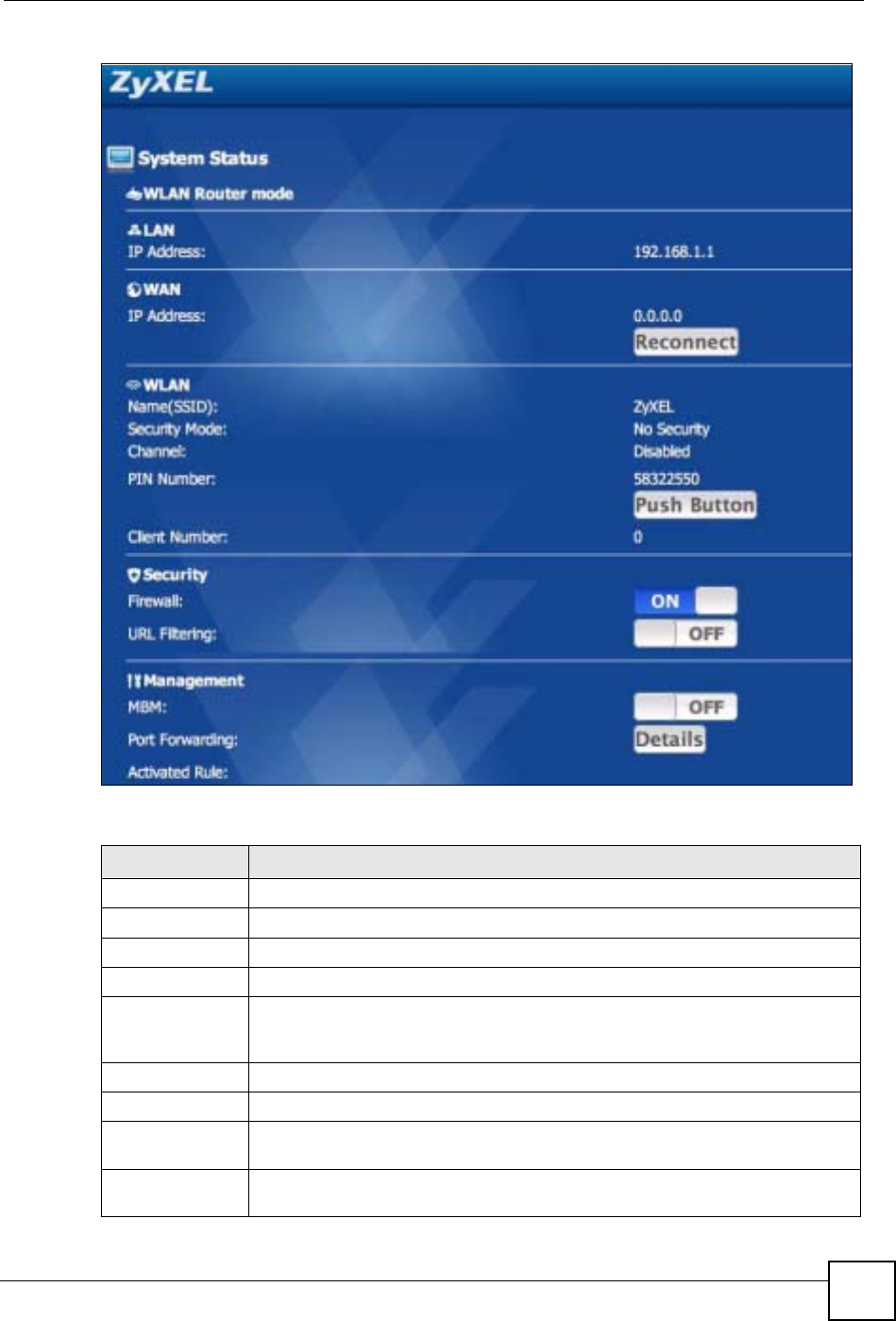
Chapter 7 Wireless LAN
NBG-460N User’s Guide 111
Figure 74 System Status screen
The following table describes the labels in this screen.
Table 41 System Status screen
LABEL DESCRIPTION
Logout Press this to logout of the iPod Touch web configurator.
LAN
IP Address This field displays the NBG-460N’s LAN (Local Area Network) IP address.
WAN
IP Address This field displays the NBG-460N’s WAN IP address. If this field displays “-” it
means the WAN is not connected. Try pressing Reconnect if your WAN
connection is not working.
Reconnect Press Reconnect to renew your NBG-460N’s WAN connection.
WLAN
Name (SSID) This field displays the SSID (Service set identifier) of the NBG-460N’s Wireless
LAN.
Security Mode This field displays the security authentication mode of the NBG-460N’s Wireless
LAN. This can be No Security,WPA-PSK,WPA2-PSK or WEP.

Chapter 7 Wireless LAN
NBG-460N User’s Guide
112
7.10.3 WPS in Progress
After pressing Push Button in the System Status screen the WPS in Progress screen will
display.
It can take around two minutes for a successful WPS connection to be made. The System
Status screen will display after a connection has been made or if it has failed. For more
information on WPS see Section 7.9 on page 106.
Channel This field displays the channel the NBG-460N’s Wireless LAN operates on. This
will display as disabled if auto channel selection mode is on.
PIN Number This field displays the NBG-460N’s WPS (Wi-Fi Protected Setup) PIN number.
WPS allows you to connect wireless clients to your wireless LAN easily. See
Section 7.9 on page 106 for more information on WPS and the PIN method of
configuration.
Push Button Press the Push Button to start either the PBC (Push Button Configuration) or PIN
method of WPS configuration. The WPS in progress screen will display, see
Section 7.10.3 on page 112.
Client Number This field displays the number of wireless clients on the network.
Security
Firewall Press the left side of the button to turn the firewall ON. Press the right side of the
button to turn the firewall OFF. To configure the firewall access the web
configurator from your computer.
A Firewall enables the NBG-460N to act as a secure gateway between the LAN
and the Internet.
URL Filtering Press the left side of the button to turn URL Filtering ON. Press the right side of
the button to turn URL Filtering OFF. To configure URL filtering access the web
configurator from your computer and go to the content filtering screens.
Content filtering enables you to block certain web features or specific URL
keywords.
Management
MBM Press the left side of the button to turn MBM (Media Bandwidth Management) ON.
Press the right side of the button to turn MBM OFF. To configure Media Bandwidth
Management access the web configurator from your computer and go to the
Bandwidth Management screens.
When accessed from a computer the web configurator allows you to specify
bandwidth management rules based on an application and/or subnet.
Port
Forwarding Press Details to go to another screen to manage the port forwarding rules.
Activated Rule This field displays the currently activated port forwarding rules.
Table 41 System Status screen
LABEL DESCRIPTION

Chapter 7 Wireless LAN
NBG-460N User’s Guide 113
Figure 75 WPS In Progress
7.10.4 Port Forwarding
After pressing the Details button in the System Status screen the port forwarding screen will
display. Use this screen to change the status of port forwarding rules that have been set up in
the web configurator from your computer. See Section 11.4 on page 139 for more information
on configuring port forwarding rules.
"To go back to the System Status screen press the ZyXEL logo at the top of
the page.
"To see any changes on the System Status screen you will need to refresh the
page first. Use the browser’s refresh function. See the iPod Touch’s
documentation if you cannot find it.
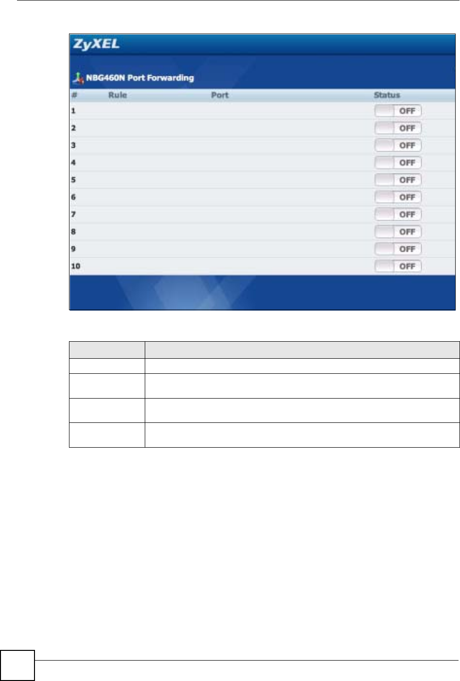
Chapter 7 Wireless LAN
NBG-460N User’s Guide
114
Figure 76 Port Forwarding
The following table describes the labels in this screen.
7.11 Accessing the iPod Touch Web Configurator
To access the iPod Touch web configurator through your iPod Touch you must first connect it
to the NBG-460N’s wireless network. Follow the steps below to do this.
Table 42 Port Forwarding
LABEL DESCRIPTION
#This is the number of an individual port forwarding entry.
Rule This column displays the configured port forwarding rules. To configure a new rule
you must use the web configurator from your computer.
Port This column displays the port number(s) which are forwarded when the rule is
turned on.
Status Use this column to manage the status of the rules. Press the left side of the button
to turn the rule ON and press the right side of the button to turn the rule OFF.
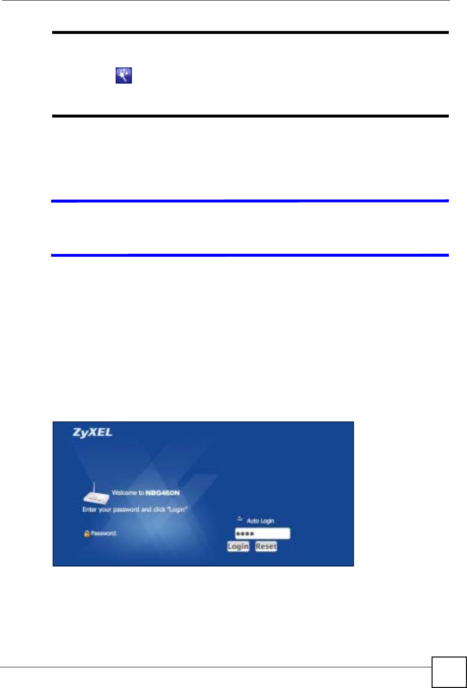
Chapter 7 Wireless LAN
NBG-460N User’s Guide 115
"If you have not configured your wireless settings yet you can do so by using
the Wizard in the web configurator you access from your computer. Click the
Wizard icon or the Go To Wizard Setup web link you see after logging
into the web configurator from your computer. See Chapter 4 on page 49 for
more information on using the Wizard.
1On the iPod Touch’s main screen press Settings and then press Wi-fi.
2On the list of networks press the NBG-460N’s network name (SSID) to connect to it. If
you are prompted for any security settings enter them and press connect.
VThe pre-shared key is case-sensitive. If you have problems connecting then
try checking the security settings in the web configurator from your computer
and try again.
7.11.1 Accessing the iPod Touch Web Configurator
Now that you are connected to the NBG-460N’s wireless network you can access the iPod
Touch web configurator. To do this follow the steps below:
1Launch the iPod Touch’s web browser from the main screen. The default web browser is
Safari.
2Enter the IP address of the NBG-460N into the address bar and go to that address. The
default IP address for the NBG-460N is 192.168.1.1.
3The login screen should display.
Figure 77 Login Screen

Chapter 7 Wireless LAN
NBG-460N User’s Guide
116
VIf the login screen does not display properly, check that you are accessing the
correct IP address. Also check your iPod Touch web browser’s security
settings as they may affect how the page displays.
4If you wish to login automatically in the future make sure the Auto Login checkbox is
selected.
5Enter your password and press login. The default password for the NBG-460N is
“1234”.
6The System Status screen will display after successfully logging in. Congratulations!
For information on using the configurator see Section 7.10 on page 108.

NBG-460N User’s Guide 117
CHAPTER 8
WAN
This chapter describes how to configure WAN settings.
8.1 WAN Overview
See the chapter about the connection wizard for more information on the fields in the WAN
screens.
8.2 WAN MAC Address
The MAC address screen allows users to configure the WAN port's MAC address by either
using the factory default or cloning the MAC address from a computer on your LAN. Choose
Factory Default to select the factory assigned default MAC Address.
Otherwise, click Clone the computer's MAC address - IP Address and enter the IP address
of the computer on the LAN whose MAC you are cloning. Once it is successfully configured,
the address will be copied to the rom file (ZyNOS configuration file). It will not change unless
you change the setting or upload a different ROM file. It is recommended that you clone the
MAC address prior to hooking up the WAN Port.
8.3 Multicast
Traditionally, IP packets are transmitted in one of either two ways - Unicast (1 sender - 1
recipient) or Broadcast (1 sender - everybody on the network). Multicast delivers IP packets to
a group of hosts on the network - not everybody and not just 1.
IGMP (Internet Group Multicast Protocol) is a network-layer protocol used to establish
membership in a Multicast group - it is not used to carry user data. IGMP version 2 (RFC
2236) is an improvement over version 1 (RFC 1112) but IGMP version 1 is still in wide use. If
you would like to read more detailed information about interoperability between IGMP
version 2 and version 1, please see sections 4 and 5 of RFC 2236. The class D IP address is
used to identify host groups and can be in the range 224.0.0.0 to 239.255.255.255. The address
224.0.0.0 is not assigned to any group and is used by IP multicast computers. The address
224.0.0.1 is used for query messages and is assigned to the permanent group of all IP hosts
(including gateways). All hosts must join the 224.0.0.1 group in order to participate in IGMP.
The address 224.0.0.2 is assigned to the multicast routers group.
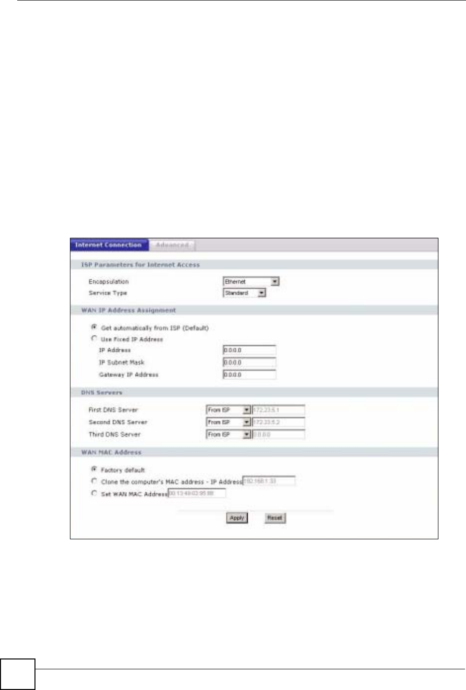
Chapter 8 WAN
NBG-460N User’s Guide
118
The NBG-460N supports both IGMP version 1 (IGMP-v1) and IGMP version 2 (IGMP-v2).
At start up, the NBG-460N queries all directly connected networks to gather group
membership. After that, the NBG-460N periodically updates this information. IP multicasting
can be enabled/disabled on the NBG-460N LAN and/or WAN interfaces in the web
configurator (LAN; WAN). Select None to disable IP multicasting on these interfaces.
8.4 Internet Connection
Use this screen to change your NBG-460N’s Internet access settings. Click Network > WAN.
The screen differs according to the encapsulation you choose.
8.4.1 Ethernet Encapsulation
This screen displays when you select Ethernet encapsulation.
Figure 78 Network > WAN > Internet Connection: Ethernet Encapsulation

Chapter 8 WAN
NBG-460N User’s Guide 119
The following table describes the labels in this screen.
8.4.2 PPPoE Encapsulation
The NBG-460N supports PPPoE (Point-to-Point Protocol over Ethernet). PPPoE is an IETF
standard (RFC 2516) specifying how a personal computer (PC) interacts with a broadband
modem (DSL, cable, wireless, etc.) connection. The PPP over Ethernet option is for a dial-
up connection using PPPoE.
Table 43 Network > WAN > Internet Connection: Ethernet Encapsulation
LABEL DESCRIPTION
Encapsulation You must choose the Ethernet option when the WAN port is used as a regular
Ethernet.
Service Type Choose from Standard,RR-Telstra (RoadRunner Telstra authentication
method), RR-Manager (Roadrunner Manager authentication method), RR-
Toshiba (Roadrunner Toshiba authentication method) or Telia Login.
The following fields do not appear with the Standard service type.
WAN IP Address Assignment
Get automatically
from ISP Select this option If your ISP did not assign you a fixed IP address. This is the
default selection.
Use Fixed IP
Address Select this option If the ISP assigned a fixed IP address.
IP Address Enter your WAN IP address in this field if you selected Use Fixed IP Address.
IP Subnet
Mask Enter the IP Subnet Mask in this field.
Gateway IP
Address Enter a Gateway IP Address (if your ISP gave you one) in this field.
DNS Servers
First DNS Server
Second DNS
Server
Third DNS Server
Select From ISP if your ISP dynamically assigns DNS server information (and the
NBG-460N's WAN IP address). The field to the right displays the (read-only) DNS
server IP address that the ISP assigns.
Select User-Defined if you have the IP address of a DNS server. Enter the DNS
server's IP address in the field to the right. If you chose User-Defined, but leave
the IP address set to 0.0.0.0, User-Defined changes to None after you click
Apply. If you set a second choice to User-Defined, and enter the same IP
address, the second User-Defined changes to None after you click Apply.
Select None if you do not want to configure DNS servers. If you do not configure
a DNS server, you must know the IP address of a computer in order to access it.
WAN MAC
Address The MAC address section allows users to configure the WAN port's MAC address
by either using the NBG-460N’s MAC address, copying the MAC address from a
computer on your LAN or manually entering a MAC address.
Factory default Select Factory default to use the factory assigned default MAC Address.
Clone the
computer’s MAC
address
Select Clone the computer's MAC address - IP Address and enter the IP
address of the computer on the LAN whose MAC you are cloning. Once it is
successfully configured, the address will be copied to the rom file (ZyNOS
configuration file). It will not change unless you change the setting or upload a
different ROM file.
Set WAN MAC
Address Select this option and enter the MAC address you want to use.
Apply Click Apply to save your changes back to the NBG-460N.
Reset Click Reset to begin configuring this screen afresh.
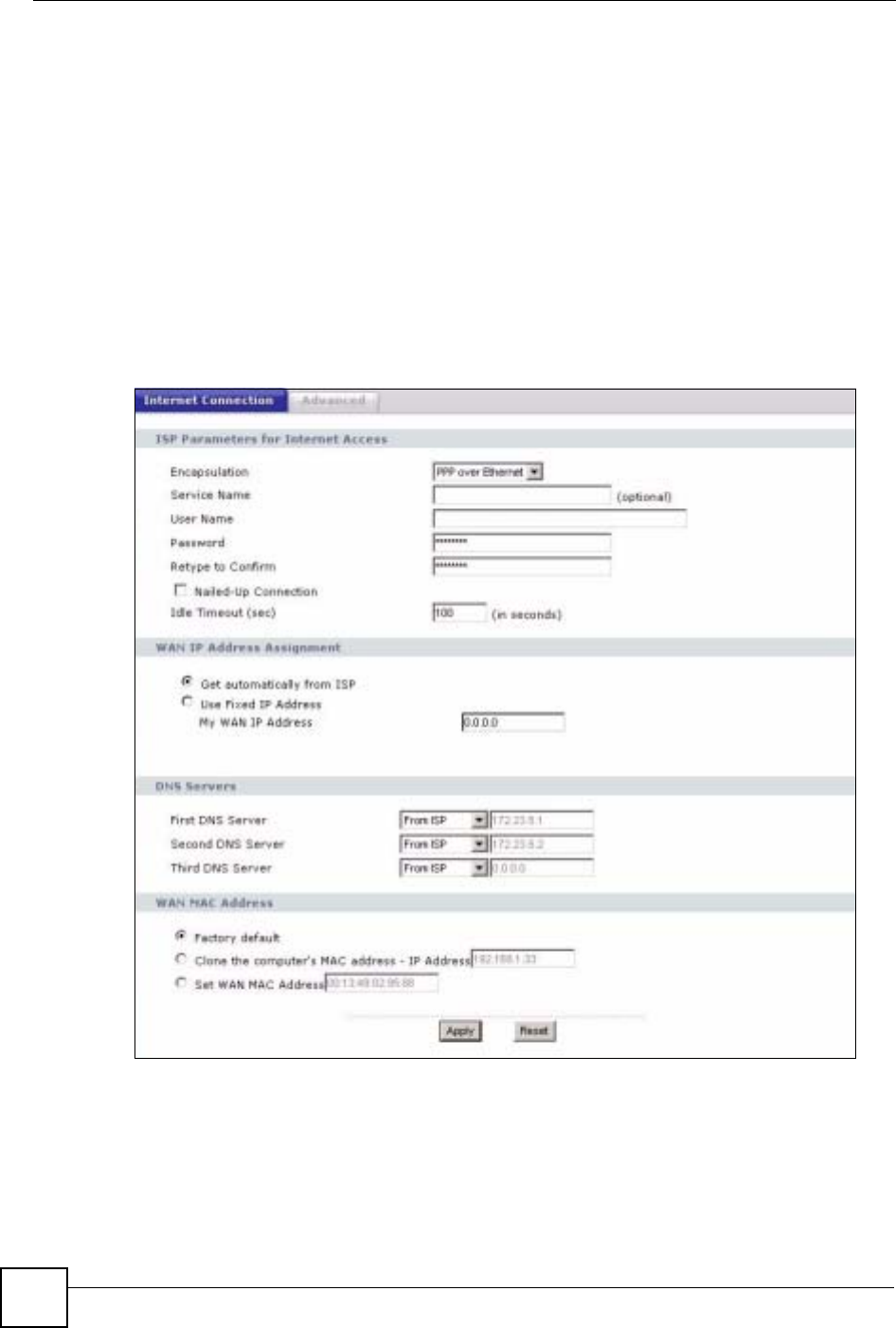
Chapter 8 WAN
NBG-460N User’s Guide
120
For the service provider, PPPoE offers an access and authentication method that works with
existing access control systems (for example Radius).
One of the benefits of PPPoE is the ability to let you access one of multiple network services,
a function known as dynamic service selection. This enables the service provider to easily
create and offer new IP services for individuals.
Operationally, PPPoE saves significant effort for both you and the ISP or carrier, as it requires
no specific configuration of the broadband modem at the customer site.
By implementing PPPoE directly on the NBG-460N (rather than individual computers), the
computers on the LAN do not need PPPoE software installed, since the NBG-460N does that
part of the task. Furthermore, with NAT, all of the LANs’ computers will have access.
This screen displays when you select PPPoE encapsulation.
Figure 79 Network > WAN > Internet Connection: PPPoE Encapsulation

Chapter 8 WAN
NBG-460N User’s Guide 121
The following table describes the labels in this screen.
Table 44 Network > WAN > Internet Connection: PPPoE Encapsulation
LABEL DESCRIPTION
ISP Parameters for Internet Access
Encapsulation The PPP over Ethernet choice is for a dial-up connection using PPPoE. The NBG-
460N supports PPPoE (Point-to-Point Protocol over Ethernet). PPPoE is an IETF
Draft standard (RFC 2516) specifying how a personal computer (PC) interacts with
a broadband modem (i.e. xDSL, cable, wireless, etc.) connection. Operationally,
PPPoE saves significant effort for both the end user and ISP/carrier, as it requires
no specific configuration of the broadband modem at the customer site. By
implementing PPPoE directly on the router rather than individual computers, the
computers on the LAN do not need PPPoE software installed, since the router does
that part of the task. Further, with NAT, all of the LAN's computers will have access.
Service Name Type the PPPoE service name provided to you. PPPoE uses a service name to
identify and reach the PPPoE server.
User Name Type the user name given to you by your ISP.
Password Type the password associated with the user name above.
Retype to
Confirm Type your password again to make sure that you have entered is correctly.
Nailed-Up
Connection Select Nailed-Up Connection if you do not want the connection to time out.
Idle Timeout This value specifies the time in seconds that elapses before the router
automatically disconnects from the PPPoE server.
WAN IP Address Assignment
Get automatically
from ISP Select this option If your ISP did not assign you a fixed IP address. This is the
default selection.
Use Fixed IP
Address Select this option If the ISP assigned a fixed IP address.
My WAN IP
Address Enter your WAN IP address in this field if you selected Use Fixed IP Address.
DNS Servers
First DNS Server
Second DNS
Server
Third DNS Server
Select From ISP if your ISP dynamically assigns DNS server information (and the
NBG-460N's WAN IP address). The field to the right displays the (read-only) DNS
server IP address that the ISP assigns.
Select User-Defined if you have the IP address of a DNS server. Enter the DNS
server's IP address in the field to the right. If you chose User-Defined, but leave
the IP address set to 0.0.0.0, User-Defined changes to None after you click
Apply. If you set a second choice to User-Defined, and enter the same IP
address, the second User-Defined changes to None after you click Apply.
Select None if you do not want to configure DNS servers. If you do not configure a
DNS server, you must know the IP address of a computer in order to access it.
WAN MAC
Address The MAC address section allows users to configure the WAN port's MAC address
by using the NBG-460N’s MAC address, copying the MAC address from a
computer on your LAN or manually entering a MAC address.
Factory default Select Factory default to use the factory assigned default MAC Address.
Clone the
computer’s MAC
address
Select Clone the computer's MAC address - IP Address and enter the IP
address of the computer on the LAN whose MAC you are cloning. Once it is
successfully configured, the address will be copied to the rom file (ZyNOS
configuration file). It will not change unless you change the setting or upload a
different ROM file.
Set WAN MAC
Address Select this option and enter the MAC address you want to use.

Chapter 8 WAN
NBG-460N User’s Guide
122
8.4.3 PPTP Encapsulation
Point-to-Point Tunneling Protocol (PPTP) is a network protocol that enables secure transfer of
data from a remote client to a private server, creating a Virtual Private Network (VPN) using
TCP/IP-based networks.
PPTP supports on-demand, multi-protocol and virtual private networking over public
networks, such as the Internet.
This screen displays when you select PPTP encapsulation.
Apply Click Apply to save your changes back to the NBG-460N.
Reset Click Reset to begin configuring this screen afresh.
Table 44 Network > WAN > Internet Connection: PPPoE Encapsulation
LABEL DESCRIPTION
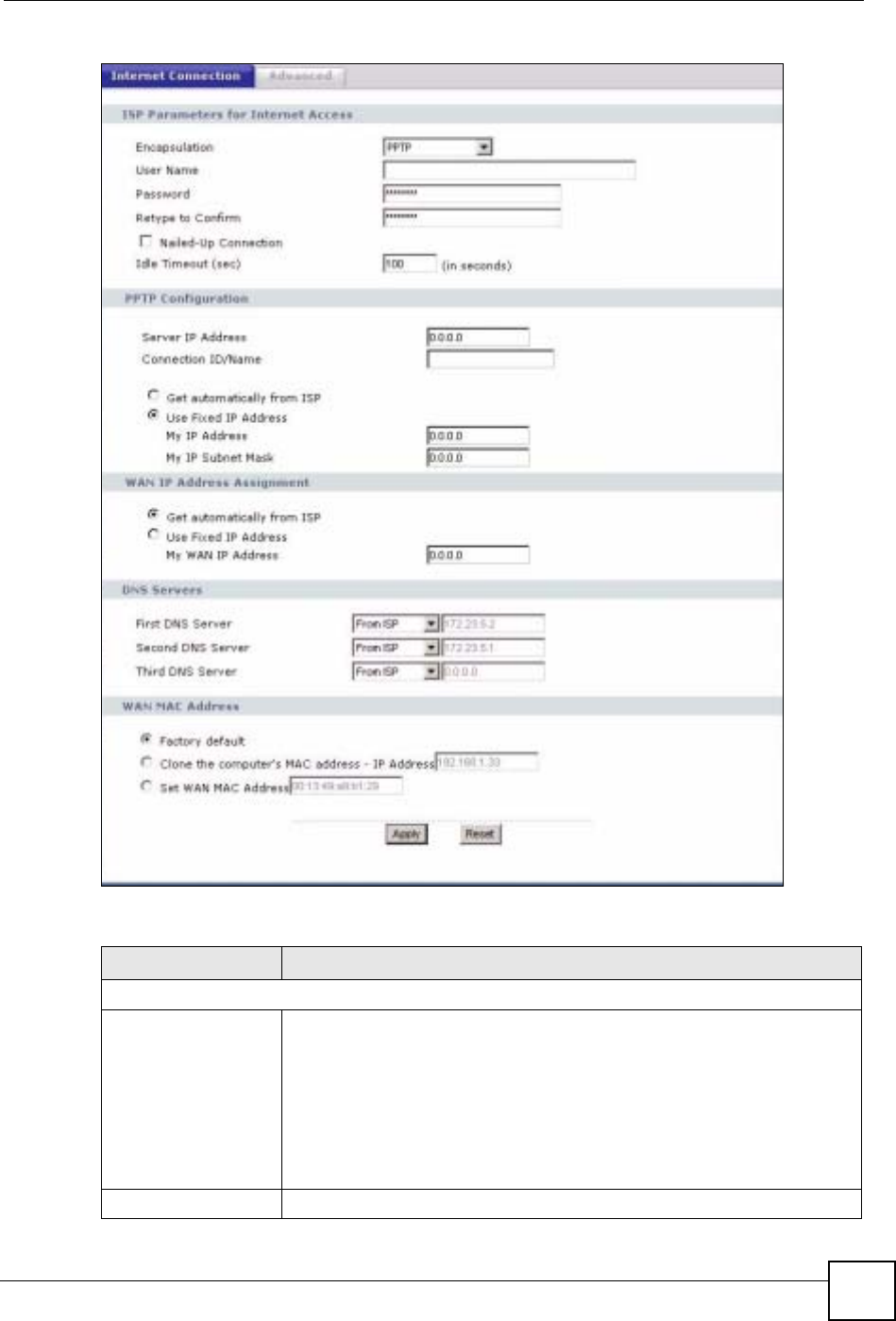
Chapter 8 WAN
NBG-460N User’s Guide 123
Figure 80 Network > WAN > Internet Connection: PPTP Encapsulation
The following table describes the labels in this screen.
Table 45 Network > WAN > Internet Connection: PPTP Encapsulation
LABEL DESCRIPTION
ISP Parameters for Internet Access
Encapsulation Point-to-Point Tunneling Protocol (PPTP) is a network protocol that enables
secure transfer of data from a remote client to a private server, creating a
Virtual Private Network (VPN) using TCP/IP-based networks. PPTP supports
on-demand, multi-protocol, and virtual private networking over public
networks, such as the Internet. The NBG-460N supports only one PPTP
server connection at any given time.
To configure a PPTP client, you must configure the User Name and
Password fields for a PPP connection and the PPTP parameters for a PPTP
connection.
User Name Type the user name given to you by your ISP.

Chapter 8 WAN
NBG-460N User’s Guide
124
Password Type the password associated with the User Name above.
Retype to Confirm Type your password again to make sure that you have entered is correctly.
Nailed-up Connection Select Nailed-Up Connection if you do not want the connection to time out.
Idle Timeout This value specifies the time in seconds that elapses before the NBG-460N
automatically disconnects from the PPTP server.
PPTP Configuration
Server IP Address Type the IP address of the PPTP server.
Connection ID/Name Type your identification name for the PPTP server.
Get automatically from
ISP Select this option If your ISP did not assign you a fixed IP address. This is the
default selection.
Use Fixed IP Address Select this option If the ISP assigned a fixed IP address.
My IP Address Type the (static) IP address assigned to you by your ISP.
My IP Subnet
Mask Your NBG-460N will automatically calculate the subnet mask based on the IP
address that you assign. Unless you are implementing subnetting, use the
subnet mask computed by the NBG-460N.
WAN IP Address Assignment
Get automatically from
ISP Select this option If your ISP did not assign you a fixed IP address. This is the
default selection.
Use Fixed IP Address Select this option If the ISP assigned a fixed IP address.
My WAN IP
Address Enter your WAN IP address in this field if you selected Use Fixed IP
Address.
DNS Servers
First DNS Server
Second DNS Server
Third DNS Server
Select From ISP if your ISP dynamically assigns DNS server information (and
the NBG-460N's WAN IP address). The field to the right displays the (read-
only) DNS server IP address that the ISP assigns.
Select User-Defined if you have the IP address of a DNS server. Enter the
DNS server's IP address in the field to the right. If you chose User-Defined,
but leave the IP address set to 0.0.0.0, User-Defined changes to None after
you click Apply. If you set a second choice to User-Defined, and enter the
same IP address, the second User-Defined changes to None after you click
Apply.
Select None if you do not want to configure DNS servers. If you do not
configure a DNS server, you must know the IP address of a computer in order
to access it.
WAN MAC Address The MAC address section allows users to configure the WAN port's MAC
address by either using the NBG-460N’s MAC address, copying the MAC
address from a computer on your LAN or manually entering a MAC address.
Factory default Select Factory default to use the factory assigned default MAC Address.
Clone the computer’s
MAC address Select Clone the computer's MAC address - IP Address and enter the IP
address of the computer on the LAN whose MAC you are cloning. Once it is
successfully configured, the address will be copied to the rom file (ZyNOS
configuration file). It will not change unless you change the setting or upload a
different ROM file.
Set WAN MAC
Address Select this option and enter the MAC address you want to use.
Apply Click Apply to save your changes back to the NBG-460N.
Reset Click Reset to begin configuring this screen afresh.
Table 45 Network > WAN > Internet Connection: PPTP Encapsulation
LABEL DESCRIPTION
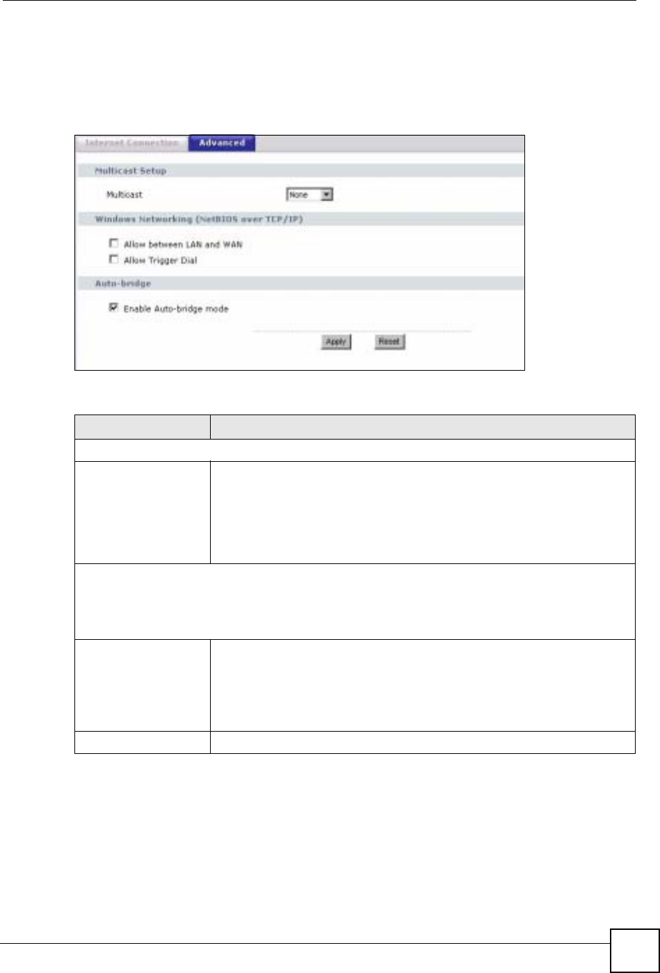
Chapter 8 WAN
NBG-460N User’s Guide 125
8.5 Advanced WAN Screen
To change your NBG-460N’s advanced WAN settings, click Network > WAN > Advanced.
The screen appears as shown.
Figure 81 Network > WAN > Advanced
The following table describes the labels in this screen.
Table 46 WAN > Advanced
LABEL DESCRIPTION
Multicast Setup
Multicast Select IGMP V-1,IGMP V-2 or None. IGMP (Internet Group Multicast
Protocol) is a network-layer protocol used to establish membership in a
Multicast group - it is not used to carry user data. IGMP version 2 (RFC 2236)
is an improvement over version 1 (RFC 1112) but IGMP version 1 is still in
wide use. If you would like to read more detailed information about
interoperability between IGMP version 2 and version 1, please see sections 4
and 5 of RFC 2236.
Windows Networking (NetBIOS over TCP/IP): NetBIOS (Network Basic Input/Output System) are TCP
or UDP broadcast packets that enable a computer to connect to and communicate with a LAN. For
some dial-up services such as PPPoE or PPTP, NetBIOS packets cause unwanted calls. However it
may sometimes be necessary to allow NetBIOS packets to pass through to the WAN in order to find a
computer on the WAN.
Allow between LAN
and WAN Select this check box to forward NetBIOS packets from the LAN to the WAN
and from the WAN to the LAN. If your firewall is enabled with the default
policy set to block WAN to LAN traffic, you also need to enable the default
WAN to LAN firewall rule that forwards NetBIOS traffic.
Clear this check box to block all NetBIOS packets going from the LAN to the
WAN and from the WAN to the LAN.
Allow Trigger Dial Select this option to allow NetBIOS packets to initiate calls.

Chapter 8 WAN
NBG-460N User’s Guide
126
Enable Auto-bridge
mode Select this option to have the NBG-460N switch to bridge mode automatically
when the NBG-460N gets a WAN IP address in the range of 192.168.x.y
(where x and y are from zero to nine) no matter what the LAN IP address is.
This might happen if you put the NBG-460N behind a NAT router that assigns
it this IP address. When the NBG-460N is in bridge mode, the NBG-460N
acts as an AP and all the interfaces (LAN, WAN and WLAN) are bridged. In
this mode, your NAT, DHCP server, firewall and bandwidth management
(rules) on the NBG-460N are not available. You do not have to reconfigure
them if you return to router mode.
Note: The NBG-460N automatically turns back to Router Mode
when the NBG-460N gets a WAN IP address that is not
in the 192.168.x.y range.
Auto-bridging only works under the following conditions:
• The WAN IP must be 192.168.x.y (where x and y must be from zero to
nine). If the LAN IP address and the WAN IP address are in the same
subnet but x or y is greater than nine, the device operates in router mode
(with firewall and bandwidth management available).
• The device must be in Router Mode (see Chapter 24 on page 259 for
more information) for auto-bridging to become active.
Apply Click Apply to save your changes back to the NBG-460N.
Reset Click Reset to begin configuring this screen afresh.
Table 46 WAN > Advanced
LABEL DESCRIPTION

NBG-460N User’s Guide 127
CHAPTER 9
LAN
This chapter describes how to configure LAN settings.
9.1 LAN Overview
A Local Area Network (LAN) is a shared communication system to which many computers
are attached. A LAN is a computer network limited to the immediate area, usually the same
building or floor of a building. The LAN screens can help you configure a LAN DHCP server,
manage IP addresses, and partition your physical network into logical networks.
9.1.1 IP Pool Setup
The NBG-460N is pre-configured with a pool of 32 IP addresses starting from 192.168.1.33 to
192.168.1.64. This configuration leaves 31 IP addresses (excluding the NBG-460N itself) in
the lower range (192.168.1.2 to 192.168.1.32) for other server computers, for instance, servers
for mail, FTP, TFTP, web, etc., that you may have.
9.1.2 System DNS Servers
Refer to the IP address and subnet mask section in the Connection Wizard chapter.
9.2 LAN TCP/IP
The NBG-460N has built-in DHCP server capability that assigns IP addresses and DNS
servers to systems that support DHCP client capability.
9.2.1 Factory LAN Defaults
The LAN parameters of the NBG-460N are preset in the factory with the following values:
• IP address of 192.168.1.1 with subnet mask of 255.255.255.0 (24 bits)
• DHCP server enabled with 32 client IP addresses starting from 192.168.1.33.
These parameters should work for the majority of installations. If your ISP gives you explicit
DNS server address(es), read the embedded web configurator help regarding what fields need
to be configured.

Chapter 9 LAN
NBG-460N User’s Guide
128
9.2.2 IP Address and Subnet Mask
Refer to the IP address and subnet mask section in the Connection Wizard chapter for this
information.
9.2.3 Multicast
Traditionally, IP packets are transmitted in one of either two ways - Unicast (1 sender - 1
recipient) or Broadcast (1 sender - everybody on the network). Multicast delivers IP packets to
a group of hosts on the network - not everybody and not just 1.
IGMP (Internet Group Management Protocol) is a network-layer protocol used to establish
membership in a Multicast group - it is not used to carry user data. IGMP version 2 (RFC
2236) is an improvement over version 1 (RFC 1112) but IGMP version 1 is still in wide use. If
you would like to read more detailed information about interoperability between IGMP
version 2 and version 1, please see sections 4 and 5 of RFC 2236. The class D IP address is
used to identify host groups and can be in the range 224.0.0.0 to 239.255.255.255. The address
224.0.0.0 is not assigned to any group and is used by IP multicast computers. The address
224.0.0.1 is used for query messages and is assigned to the permanent group of all IP hosts
(including gateways). All hosts must join the 224.0.0.1 group in order to participate in IGMP.
The address 224.0.0.2 is assigned to the multicast routers group.
The NBG-460N supports both IGMP version 1 (IGMP-v1) and IGMP version 2 (IGMP-v2).
At start up, the NBG-460N queries all directly connected networks to gather group
membership. After that, the NBG-460N periodically updates this information. IP multicasting
can be enabled/disabled on the NBG-460N LAN and/or WAN interfaces in the web
configurator (LAN; WAN). Select None to disable IP multicasting on these interfaces.
9.2.4 Any IP
Traditionally, you must set the IP addresses and the subnet masks of a computer and the NBG-
460N to be in the same subnet to allow the computer to access the Internet (through the NBG-
460N). In cases where your computer is required to use a static IP address in another network,
you may need to manually configure the network settings of the computer every time you want
to access the Internet via the NBG-460N.
With the Any IP feature and NAT enabled, the NBG-460N allows a computer to access the
Internet without changing the network settings (such as IP address and subnet mask) of the
computer, when the IP addresses of the computer and the NBG-460N are not in the same
subnet. Whether a computer is set to use a dynamic or static (fixed) IP address, you can simply
connect the computer to the NBG-460N and access the Internet.
The following figure depicts a scenario where a computer is set to use a static private IP
address in the corporate environment. In a residential house where a NBG-460N is installed,
you can still use the computer to access the Internet without changing the network settings,
even when the IP addresses of the computer and the NBG-460N are not in the same subnet.
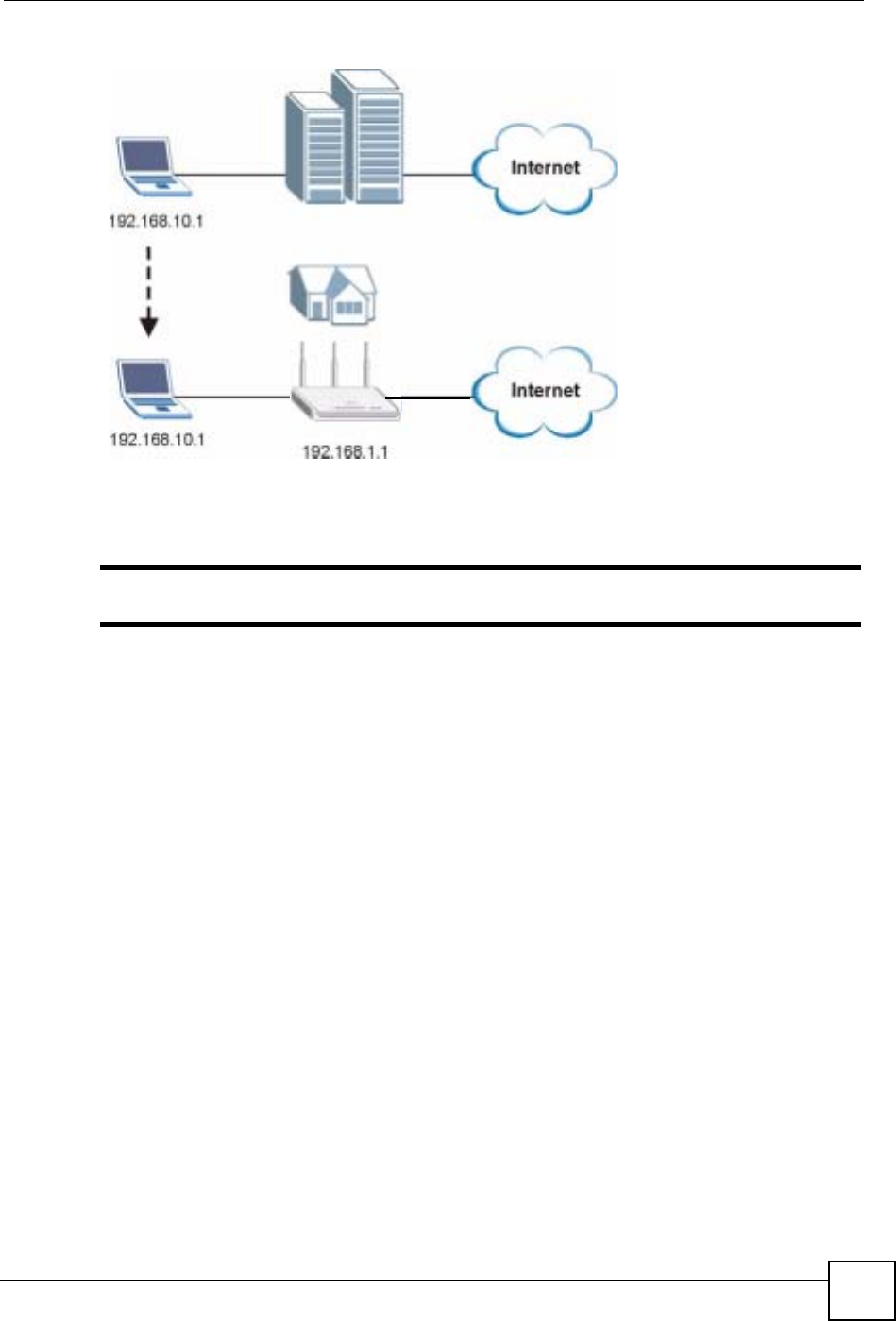
Chapter 9 LAN
NBG-460N User’s Guide 129
Figure 82 Any IP Example
The Any IP feature does not apply to a computer using either a dynamic IP address or a static
IP address that is in the same subnet as the NBG-460N’s IP address.
"You must enable NAT to use the Any IP feature on the NBG-460N.
Address Resolution Protocol (ARP) is a protocol for mapping an Internet Protocol address (IP
address) to a physical machine address, also known as a Media Access Control or MAC
address, on the local area network. IP routing table is defined on IP Ethernet devices (the
NBG-460N) to decide which hop to use, to help forward data along to its specified destination.
The following lists out the steps taken, when a computer tries to access the Internet for the first
time through the NBG-460N.
1When a computer (which is in a different subnet) first attempts to access the Internet, it
sends packets to its default gateway (which is not the NBG-460N) by looking at the
MAC address in its ARP table.
2When the computer cannot locate the default gateway, an ARP request is broadcast on
the LAN.
3The NBG-460N receives the ARP request and replies to the computer with its own MAC
address.
4The computer updates the MAC address for the default gateway to the ARP table. Once
the ARP table is updated, the computer is able to access the Internet through the NBG-
460N.
5When the NBG-460N receives packets from the computer, it creates an entry in the IP
routing table so it can properly forward packets intended for the computer.
After all the routing information is updated, the computer can access the NBG-460N and the
Internet as if it is in the same subnet as the NBG-460N.
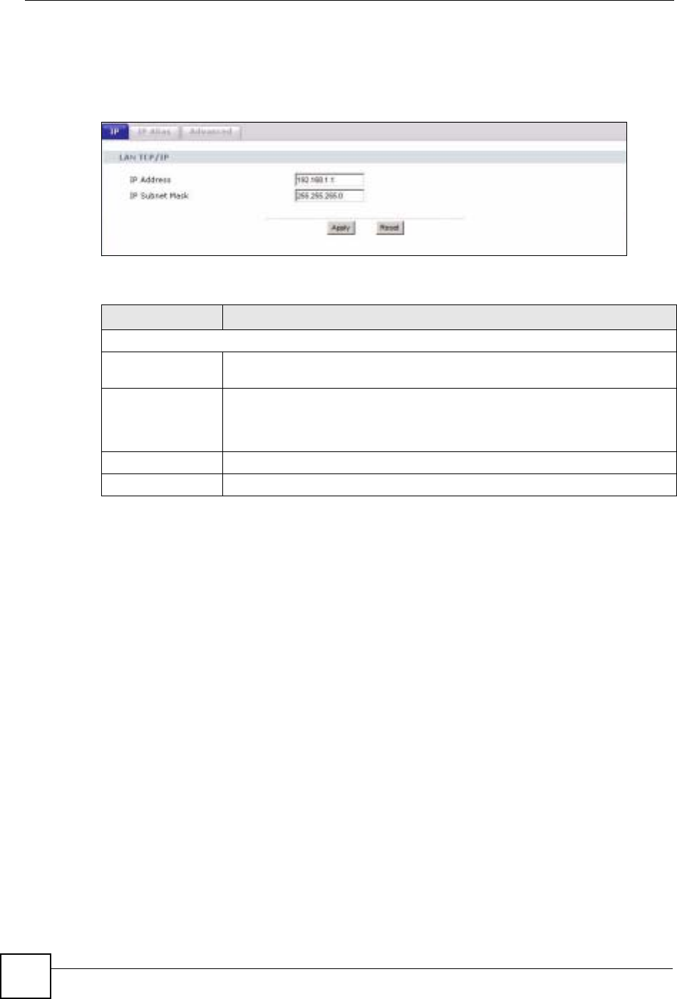
Chapter 9 LAN
NBG-460N User’s Guide
130
9.3 LAN IP Screen
Use this screen to change your basic LAN settings. Click Network > LAN.
Figure 83 Network > LAN > IP
The following table describes the labels in this screen.
9.4 LAN IP Alias
IP alias allows you to partition a physical network into different logical networks over the
same Ethernet interface. The NBG-460N supports three logical LAN interfaces via its single
physical Ethernet interface with the NBG-460N itself as the gateway for each LAN network.
To change your NBG-460N’s IP alias settings, click Network > LAN > IP Alias. The screen
appears as shown.
Table 47 Network > LAN > IP
LABEL DESCRIPTION
LAN TCP/IP
IP Address Type the IP address of your NBG-460N in dotted decimal notation 192.168.1.1
(factory default).
IP Subnet Mask The subnet mask specifies the network number portion of an IP address. Your
NBG-460N will automatically calculate the subnet mask based on the IP address
that you assign. Unless you are implementing subnetting, use the subnet mask
computed by the NBG-460N.
Apply Click Apply to save your changes back to the NBG-460N.
Reset Click Reset to begin configuring this screen afresh.
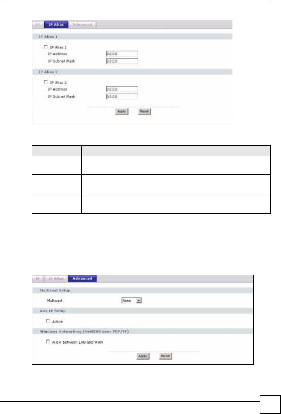
Chapter 9 LAN
NBG-460N User’s Guide 131
Figure 84 Network > LAN > IP Alias
The following table describes the labels in this screen.
9.5 Advanced LAN Screen
To change your NBG-460N’s advanced IP settings, click Network > LAN > Advanced. The
screen appears as shown.
Figure 85 Network > LAN > Advanced
Table 48 Network > LAN > IP Alias
LABEL DESCRIPTION
IP Alias 1,2 Select the check box to configure another LAN network for the NBG-460N.
IP Address Enter the IP address of your NBG-460N in dotted decimal notation.
IP Subnet Mask Your NBG-460N will automatically calculate the subnet mask based on the IP
address that you assign. Unless you are implementing subnetting, use the
subnet mask computed by the NBG-460N.
Apply Click Apply to save your changes back to the NBG-460N.
Reset Click Reset to begin configuring this screen afresh.

Chapter 9 LAN
NBG-460N User’s Guide
132
The following table describes the labels in this screen.
Table 49 Network > LAN > Advanced
LABEL DESCRIPTION
Multicast Select IGMP V-1 or IGMP V-2 or None. IGMP (Internet Group Multicast
Protocol) is a network-layer protocol used to establish membership in a
Multicast group - it is not used to carry user data. IGMP version 2 (RFC 2236)
is an improvement over version 1 (RFC 1112) but IGMP version 1 is still in
wide use. If you would like to read more detailed information about
interoperability between IGMP version 2 and version 1, please see sections 4
and 5 of RFC 2236.
Any IP Setup
Active Select this if you want to let computers on different subnets use the NBG-
460N.
Windows Networking (NetBIOS over TCP/IP): NetBIOS (Network Basic Input/Output System) are TCP
or UDP broadcast packets that enable a computer to connect to and communicate with a LAN. For
some dial-up services such as PPPoE or PPTP, NetBIOS packets cause unwanted calls. However it
may sometimes be necessary to allow NetBIOS packets to pass through to the WAN in order to find a
computer on the WAN.
Allow between LAN
and WAN Select this check box to forward NetBIOS packets from the LAN to the WAN
and from the WAN to the LAN. If your firewall is enabled with the default policy
set to block WAN to LAN traffic, you also need to enable the default WAN to
LAN firewall rule that forwards NetBIOS traffic.
Clear this check box to block all NetBIOS packets going from the LAN to the
WAN and from the WAN to the LAN.
Apply Click Apply to save your changes back to the NBG-460N.
Reset Click Reset to begin configuring this screen afresh.
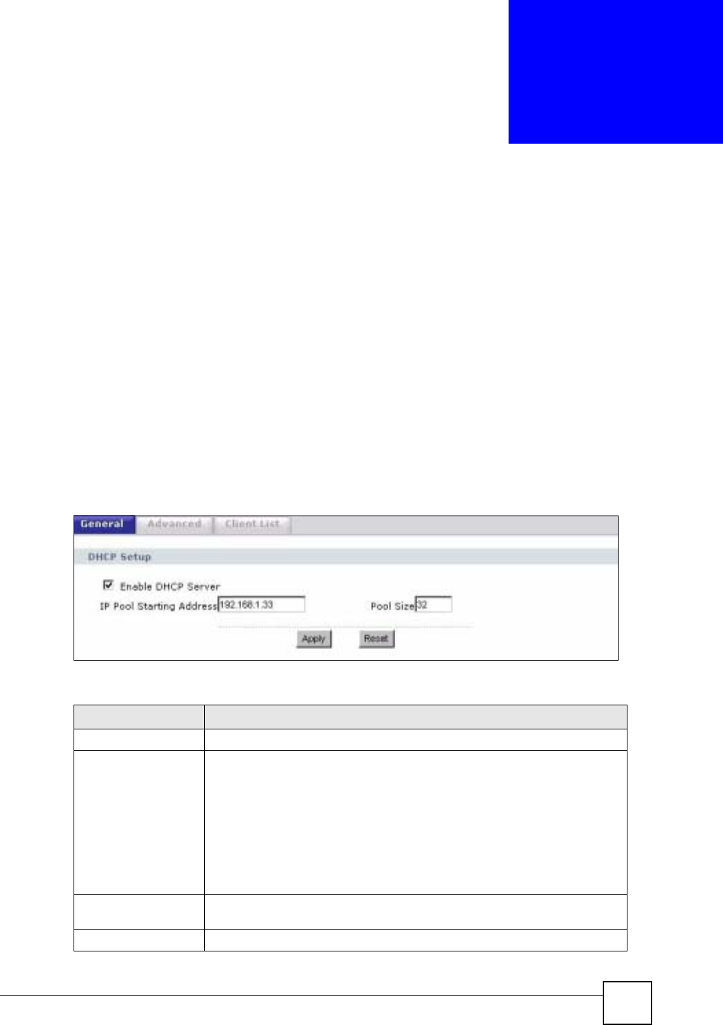
NBG-460N User’s Guide 133
CHAPTER 10
DHCP
10.1 DHCP
DHCP (Dynamic Host Configuration Protocol, RFC 2131 and RFC 2132) allows individual
clients to obtain TCP/IP configuration at start-up from a server. You can configure the NBG-
460N’s LAN as a DHCP server or disable it. When configured as a server, the NBG-460N
provides the TCP/IP configuration for the clients. If DHCP service is disabled, you must have
another DHCP server on your LAN, or else the computer must be manually configured.
10.2 DHCP General Screen
Click Network > DHCP. The following screen displays.
Figure 86 Network > DHCP > General
The following table describes the labels in this screen.
Table 50 Network > DHCP > General
LABEL DESCRIPTION
LAN DHCP Setup
Enable DHCP Server Enable or Disable DHCP for LAN.
DHCP (Dynamic Host Configuration Protocol, RFC 2131 and RFC 2132)
allows individual clients (computers) to obtain TCP/IP configuration at startup
from a server. Leave the Enable DHCP Server check box selected unless
your ISP instructs you to do otherwise. Clear it to disable the NBG-460N
acting as a DHCP server. When configured as a server, the NBG-460N
provides TCP/IP configuration for the clients. If not, DHCP service is disabled
and you must have another DHCP server on your LAN, or else the computers
must be manually configured. When set as a server, fill in the following four
fields.
IP Pool Starting
Address This field specifies the first of the contiguous addresses in the IP address pool
for LAN.
Pool Size This field specifies the size, or count of the IP address pool for LAN.
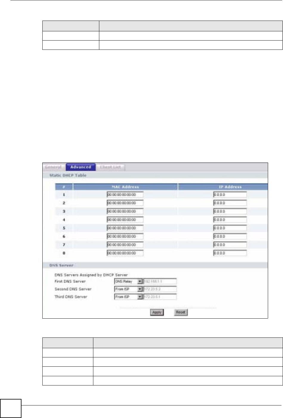
Chapter 10 DHCP
NBG-460N User’s Guide
134
10.3 DHCP Advanced Screen
This screen allows you to assign IP addresses on the LAN to specific individual computers
based on their MAC addresses. You can also use this screen to configure the DNS server
information that the NBG-460N sends to the DHCP clients.
Every Ethernet device has a unique MAC (Media Access Control) address. The MAC address
is assigned at the factory and consists of six pairs of hexadecimal characters, for example,
00:A0:C5:00:00:02.
To change your NBG-460N’s static DHCP settings, click Network > DHCP > Advanced.
The following screen displays.
Figure 87 Network > DHCP > Advanced
The following table describes the labels in this screen.
Apply Click Apply to save your changes back to the NBG-460N.
Reset Click Reset to begin configuring this screen afresh.
Table 50 Network > DHCP > General
LABEL DESCRIPTION
Table 51 Network > DHCP > Advanced
LABEL DESCRIPTION
Static DHCP Table
# This is the index number of the static IP table entry (row).
MAC Address Type the MAC address (with colons) of a computer on your LAN.
IP Address Type the LAN IP address of a computer on your LAN.

Chapter 10 DHCP
NBG-460N User’s Guide 135
10.4 Client List Screen
The DHCP table shows current DHCP client information (including IP Address,Host Name
and MAC Address) of network clients using the NBG-460N’s DHCP servers.
Configure this screen to always assign an IP address to a MAC address (and host name). Click
Network > DHCP Server > Client List.
"You can also view a read-only client list by clicking the DHCP Table
(Details...) hyperlink in the Status screen.
The following screen displays.
DNS Server
DNS Servers
Assigned by DHCP
Server
The NBG-460N passes a DNS (Domain Name System) server IP address (in the
order you specify here) to the DHCP clients. The NBG-460N only passes this
information to the LAN DHCP clients when you select the Enable DHCP Server
check box. When you clear the Enable DHCP Server check box, DHCP service
is disabled and you must have another DHCP sever on your LAN, or else the
computers must have their DNS server addresses manually configured.
First DNS Server
Second DNS
Server
Third DNS Server
Select From ISP if your ISP dynamically assigns DNS server information (and
the NBG-460N's WAN IP address). The field to the right displays the (read-only)
DNS server IP address that the ISP assigns.
Select User-Defined if you have the IP address of a DNS server. Enter the DNS
server's IP address in the field to the right. If you chose User-Defined, but leave
the IP address set to 0.0.0.0, User-Defined changes to None after you click
Apply. If you set a second choice to User-Defined, and enter the same IP
address, the second User-Defined changes to None after you click Apply.
Select DNS Relay to have the NBG-460N act as a DNS proxy. The NBG-460N's
LAN IP address displays in the field to the right (read-only). The NBG-460N tells
the DHCP clients on the LAN that the NBG-460N itself is the DNS server. When
a computer on the LAN sends a DNS query to the NBG-460N, the NBG-460N
forwards the query to the NBG-460N's system DNS server (configured in the
WAN > Internet Connection screen) and relays the response back to the
computer. You can only select DNS Relay for one of the three servers; if you
select DNS Relay for a second or third DNS server, that choice changes to
None after you click Apply.
Select None if you do not want to configure DNS servers. If you do not configure
a DNS server, you must know the IP address of a computer in order to access it.
Apply Click Apply to save your changes back to the NBG-460N.
Reset Click Reset to begin configuring this screen afresh.
Table 51 Network > DHCP > Advanced
LABEL DESCRIPTION
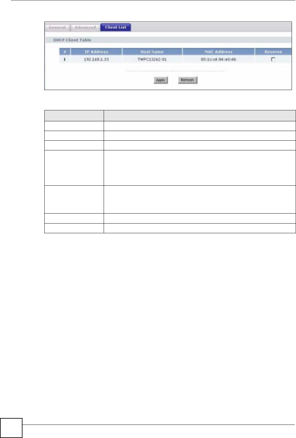
Chapter 10 DHCP
NBG-460N User’s Guide
136
Figure 88 Network > DHCP > Client List
The following table describes the labels in this screen.
Table 52 Network > DHCP > Client List
LABEL DESCRIPTION
# This is the index number of the host computer.
IP Address This field displays the IP address relative to the # field listed above.
Host Name This field displays the computer host name.
MAC Address The MAC (Media Access Control) or Ethernet address on a LAN (Local Area
Network) is unique to your computer (six pairs of hexadecimal notation).
A network interface card such as an Ethernet adapter has a hardwired
address that is assigned at the factory. This address follows an industry
standard that ensures no other adapter has a similar address.
Reserve Select this check box in the DHCP Setup section to have the NBG-460N
always assign the IP address(es) to the MAC address(es) (and host name(s)).
After you click Apply, the MAC address and IP address also display in the
Advanced screen (where you can edit them).
Apply Click Apply to save your settings.
Refresh Click Refresh to reload the DHCP table.

NBG-460N User’s Guide 137
CHAPTER 11
Network Address Translation
(NAT)
This chapter discusses how to configure NAT on the NBG-460N.
11.1 NAT Overview
NAT (Network Address Translation - NAT, RFC 1631) is the translation of the IP address of a
host in a packet. For example, the source address of an outgoing packet, used within one
network is changed to a different IP address known within another network.
11.2 Using NAT
"You must create a firewall rule in addition to setting up NAT, to allow traffic
from the WAN to be forwarded through the NBG-460N.
11.2.1 Port Forwarding: Services and Port Numbers
A port forwarding set is a list of inside (behind NAT on the LAN) servers, for example, web or
FTP, that you can make accessible to the outside world even though NAT makes your whole
inside network appear as a single machine to the outside world.
Use the Application screen to forward incoming service requests to the server(s) on your local
network. You may enter a single port number or a range of port numbers to be forwarded, and
the local IP address of the desired server. The port number identifies a service; for example,
web service is on port 80 and FTP on port 21. In some cases, such as for unknown services or
where one server can support more than one service (for example both FTP and web service),
it might be better to specify a range of port numbers.
In addition to the servers for specified services, NAT supports a default server. A service
request that does not have a server explicitly designated for it is forwarded to the default
server. If the default is not defined, the service request is simply discarded.
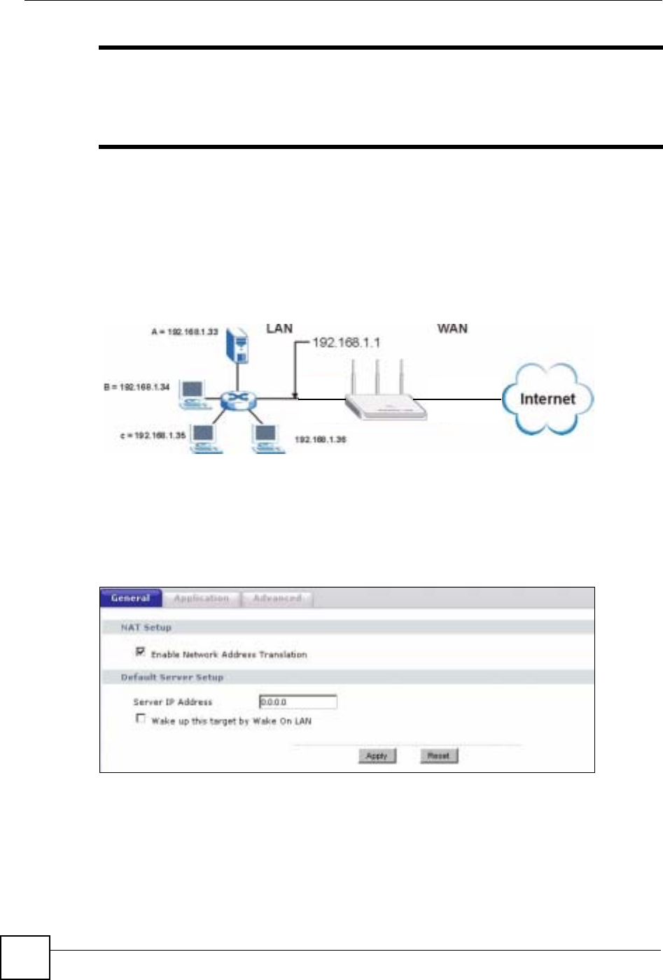
Chapter 11 Network Address Translation (NAT)
NBG-460N User’s Guide
138
"Many residential broadband ISP accounts do not allow you to run any server
processes (such as a Web or FTP server) from your location. Your ISP may
periodically check for servers and may suspend your account if it discovers
any active services at your location. If you are unsure, refer to your ISP.
11.2.2 Configuring Servers Behind Port Forwarding Example
Let's say you want to assign ports 21-25 to one FTP, Telnet and SMTP server (A in the
example), port 80 to another (B in the example) and assign a default server IP address of
192.168.1.35 to a third (C in the example). You assign the LAN IP addresses and the ISP
assigns the WAN IP address. The NAT network appears as a single host on the Internet.
Figure 89 Multiple Servers Behind NAT Example
11.3 General NAT Screen
Click Network > NAT to open the General screen.
Figure 90 Network > NAT > General

Chapter 11 Network Address Translation (NAT)
NBG-460N User’s Guide 139
The following table describes the labels in this screen.
11.4 NAT Application Screen
Port forwarding allows you to define the local servers to which the incoming services will be
forwarded. To change your NBG-460N’s port forwarding settings, click Network > NAT >
Application. The screen appears as shown.
"If you do not assign a Default Server IP address in the NAT > General
screen, the NBG-460N discards all packets received for ports that are not
specified in this screen or remote management.
Refer to Appendix F on page 321 for port numbers commonly used for particular services.
Table 53 Network > NAT > General
LABEL DESCRIPTION
Enable Network
Address
Translation
Network Address Translation (NAT) allows the translation of an Internet protocol
address used within one network (for example a private IP address used in a local
network) to a different IP address known within another network (for example a
public IP address used on the Internet).
Select the check box to enable NAT.
Default Server
Setup
Server IP
Address In addition to the servers for specified services, NAT supports a default server. A
default server receives packets from ports that are not specified in the Application
screen.
If you do not assign a Default Server IP address, the NBG-460N discards all
packets received for ports that are not specified in the Application screen or
remote management.
Wake up this
target by Wake
On LAN
Select this to use WoL (Wake On LAN) to turn on the server specified in the
Server IP Address field when packets are received on ports not specified in the
Application screen.
Note: For more information on Wake On LAN see Section 22.4 on
page 255.
Apply Click Apply to save your changes back to the NBG-460N.
Reset Click Reset to begin configuring this screen afresh.
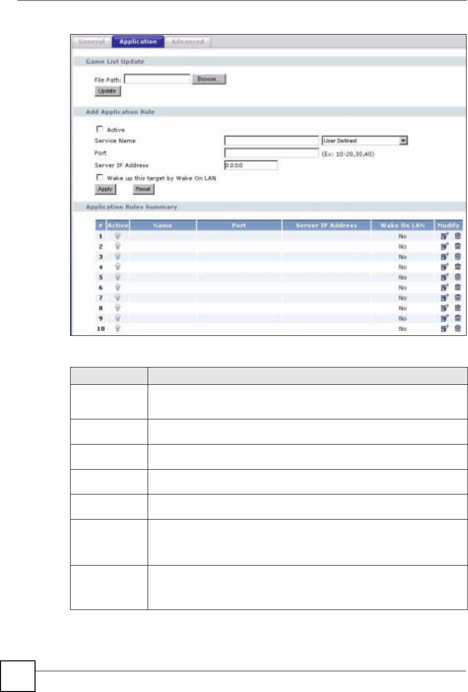
Chapter 11 Network Address Translation (NAT)
NBG-460N User’s Guide
140
Figure 91 Network > NAT > Application
The following table describes the labels in this screen.
Table 54 NAT Application
LABEL DESCRIPTION
Game List Update A game list includes the pre-defined service name(s) and port number(s). You can
edit and upload it to the NBG-460N to replace the existing entries in the second
field next to Service Name.
File Path Type in the location of the file you want to upload in this field or click Browse... to
find it.
Browse... Click Browse... to find the.txt file you want to upload. Remember that you must
decompress compressed (.zip) files before you can upload them.
Update Click Update to begin the upload process. This process may take up to two
minutes.
Add Application
Rule
Active Select the check box to enable this rule and the requested service can be
forwarded to the host with a specified internal IP address.
Clear the checkbox to disallow forwarding of these ports to an inside server
without having to delete the entry.
Service Name Type a name (of up to 31 printable characters) to identify this rule in the first field
next to Service Name. Otherwise, select a predefined service in the second field
next to Service Name. The predefined service name and port number(s) will
display in the Service Name and Port fields.

Chapter 11 Network Address Translation (NAT)
NBG-460N User’s Guide 141
11.4.1 Game List Example
Here is an example game list text file. The index number, service name and associated port(s)
are specified by semi-colons (no spaces). Use the name=xxx (where xxx is the service name)
to create a new service. Port range can be separated with a hyphen (-) (no spaces). Multiple
(non-consecutive) ports can be separated by commas.
Port Type a port number(s) to be forwarded.
To specify a range of ports, enter a hyphen (-) between the first port and the last
port, such as 10-20.
To specify two or more non-consecutive port numbers, separate them by a comma
without spaces, such as 123,567.
Server IP Address Type the inside IP address of the server that receives packets from the port(s)
specified in the Port field.
Wake up this
target by Wake
On LAN
Select this to use WoL (Wake On LAN) to turn on the server specified in the IP
address field when packets are received on the ports specified in the Port field.
Note: For more information on Wake On LAN see Section 22.4 on
page 255.
Apply Click Apply to save your changes to the Application Rules Summary table.
Reset Click Reset to not save and return your new changes in the Service Name and
Port fields to the previous one.
Application Rules
Summary
#This is the number of an individual port forwarding server entry.
Active This icon is turned on when the rule is enabled.
Name This field displays a name to identify this rule.
Port This field displays the port number(s).
Server IP Address This field displays the inside IP address of the server.
Wake On LAN This field displays No when Wake On LAN is disabled and Yes when Wake On
LAN is enabled.
Modify Click the Edit icon to display and modify an existing rule setting in the fields under
Add Application Rule.
Click the Remove icon to delete a rule.
Table 54 NAT Application (continued)
LABEL DESCRIPTION

Chapter 11 Network Address Translation (NAT)
NBG-460N User’s Guide
142
Figure 92 Game List Example
11.5 Trigger Port Forwarding
Some services use a dedicated range of ports on the client side and a dedicated range of ports
on the server side. With regular port forwarding you set a forwarding port in NAT to forward a
service (coming in from the server on the WAN) to the IP address of a computer on the client
side (LAN). The problem is that port forwarding only forwards a service to a single LAN IP
address. In order to use the same service on a different LAN computer, you have to manually
replace the LAN computer's IP address in the forwarding port with another LAN computer's IP
address.
Trigger port forwarding solves this problem by allowing computers on the LAN to
dynamically take turns using the service. The NBG-460N records the IP address of a LAN
computer that sends traffic to the WAN to request a service with a specific port number and
protocol (a "trigger" port). When the NBG-460N's WAN port receives a response with a
specific port number and protocol ("incoming" port), the NBG-460N forwards the traffic to
the LAN IP address of the computer that sent the request. After that computer’s connection for
that service closes, another computer on the LAN can use the service in the same manner. This
way you do not need to configure a new IP address each time you want a different LAN
computer to use the application.
11.5.1 Trigger Port Forwarding Example
The following is an example of trigger port forwarding.
version=1
1;name=Battlefield 1942;port=14567,22000,23000-23009,27900,28900
2;name=Call of Duty;port=28960
3;name=Civilization IV;port=2056
4;name=Diablo I and II;port=6112-6119,4000
5;name=Doom 3;port=27666
6;name=F.E.A.R;port=27888
7;name=Final Fantasy XI;port=25,80,110,443,50000-65535
8;name=Guild Wars;port=6112,80
9;name=Half Life;port=6003,7002,27005,27010,27011,27015
10;name=Jedi Knight III: Jedi Academy;port=28060-28062,28070-28081
11;name=Need for Speed: Hot Pursuit 2;port=1230,8511-
8512,27900,28900,61200-61230
12;name=Neverwinter Nights;port=5120-5300,6500,27900,28900
13;name=Quake 2;port=27910
14;name=Quake 3;port=27660,27960
15;name=Rainbow Six 3: Raven Shield;port=7777-7787,8777-8787
16;name=Serious Sam II;port=25600-25605
17;name=Silent Hunter III;port=17997-18003
18;name=Soldier of Fortune II;port=20100-20112
19;name=Starcraft;port=6112-6119,4000
20;name=Star Trek: Elite Force II;port=29250,29256
21;name=SWAT 4;port=10480-10483
22;name=Warcraft II and III;port=6112-6119,4000
23;name=World of Warcraft;port=3724
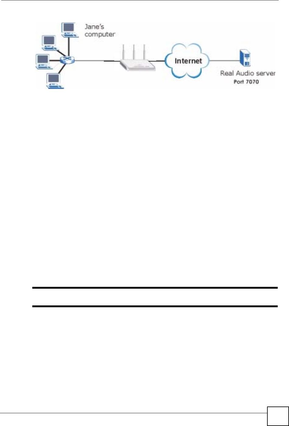
Chapter 11 Network Address Translation (NAT)
NBG-460N User’s Guide 143
Figure 93 Trigger Port Forwarding Process: Example
1Jane requests a file from the Real Audio server (port 7070).
2Port 7070 is a “trigger” port and causes the NBG-460N to record Jane’s computer IP
address. The NBG-460N associates Jane's computer IP address with the "incoming" port
range of 6970-7170.
3The Real Audio server responds using a port number ranging between 6970-7170.
4The NBG-460N forwards the traffic to Jane’s computer IP address.
5Only Jane can connect to the Real Audio server until the connection is closed or times
out. The NBG-460N times out in three minutes with UDP (User Datagram Protocol), or
two hours with TCP/IP (Transfer Control Protocol/Internet Protocol).
11.5.2 Two Points To Remember About Trigger Ports
1Trigger events only happen on data that is going coming from inside the NBG-460N and
going to the outside.
2If an application needs a continuous data stream, that port (range) will be tied up so that
another computer on the LAN can’t trigger it.
11.6 NAT Advanced Screen
To change your NBG-460N’s trigger port settings, click Network > NAT > Advanced. The
screen appears as shown.
"Only one LAN computer can use a trigger port (range) at a time.
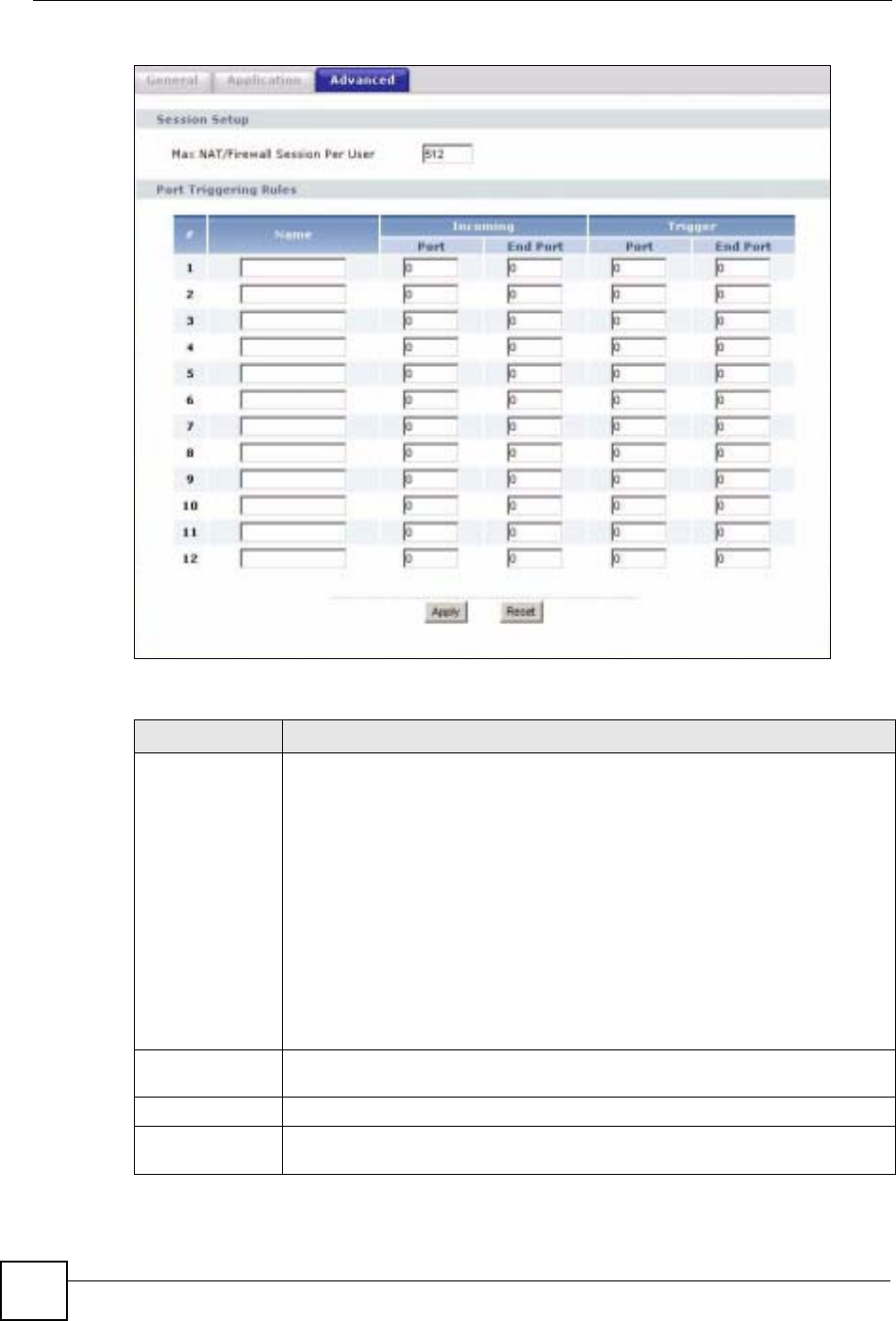
Chapter 11 Network Address Translation (NAT)
NBG-460N User’s Guide
144
Figure 94 Network > NAT > Advanced
The following table describes the labels in this screen.
Table 55 Network > NAT > Advanced
LABEL DESCRIPTION
Max NAT/Firewall
Session Per User Type a number ranging from 1 to 2048 to limit the number of NAT/firewall sessions
that a host can create.
When computers use peer to peer applications, such as file sharing
applications, they may use a large number of NAT sessions. If you do not
limit the number of NAT sessions a single client can establish, this can result in all
of the available NAT sessions being used. In this case, no additional NAT
sessions can be established, and users may not be able to access the Internet.
Each NAT session establishes a corresponding firewall session. Use this field to
limit the number of NAT/firewall sessions each client computer can establish
through the NBG-460N.
If your network has a small number of clients using peer to peer applications, you
can raise this number to ensure that their performance is not degraded by the
number of NAT sessions they can establish. If your network has a large number of
users using peer to peer applications, you can lower this number to ensure no
single client is using all of the available NAT sessions.
Port Triggering
Rules
#This is the rule index number (read-only).
Name Type a unique name (up to 15 characters) for identification purposes. All
characters are permitted - including spaces.

Chapter 11 Network Address Translation (NAT)
NBG-460N User’s Guide 145
Incoming Incoming is a port (or a range of ports) that a server on the WAN uses when it
sends out a particular service. The NBG-460N forwards the traffic with this port (or
range of ports) to the client computer on the LAN that requested the service.
Start Port Type a port number or the starting port number in a range of port numbers.
End Port Type a port number or the ending port number in a range of port numbers.
Trigger The trigger port is a port (or a range of ports) that causes (or triggers) the NBG-
460N to record the IP address of the LAN computer that sent the traffic to a server
on the WAN.
Start Port Type a port number or the starting port number in a range of port numbers.
End Port Type a port number or the ending port number in a range of port numbers.
Apply Click Apply to save your changes back to the NBG-460N.
Reset Click Reset to begin configuring this screen afresh.
Table 55 Network > NAT > Advanced
LABEL DESCRIPTION

Chapter 11 Network Address Translation (NAT)
NBG-460N User’s Guide
146

NBG-460N User’s Guide 147
CHAPTER 12
Dynamic DNS
12.1 Dynamic DNS Introduction
Dynamic DNS allows you to update your current dynamic IP address with one or many
dynamic DNS services so that anyone can contact you (in NetMeeting, CU-SeeMe, etc.). You
can also access your FTP server or Web site on your own computer using a domain name (for
instance myhost.dhs.org, where myhost is a name of your choice) that will never change
instead of using an IP address that changes each time you reconnect. Your friends or relatives
will always be able to call you even if they don't know your IP address.
First of all, you need to have registered a dynamic DNS account with www.dyndns.org. This is
for people with a dynamic IP from their ISP or DHCP server that would still like to have a
domain name. The Dynamic DNS service provider will give you a password or key.
12.1.1 DynDNS Wildcard
Enabling the wildcard feature for your host causes *.yourhost.dyndns.org to be aliased to the
same IP address as yourhost.dyndns.org. This feature is useful if you want to be able to use,
for example, www.yourhost.dyndns.org and still reach your hostname.
"If you have a private WAN IP address, then you cannot use Dynamic DNS.
12.2 Dynamic DNS Screen
To change your NBG-460N’s DDNS, click Network > DDNS. The screen appears as shown.
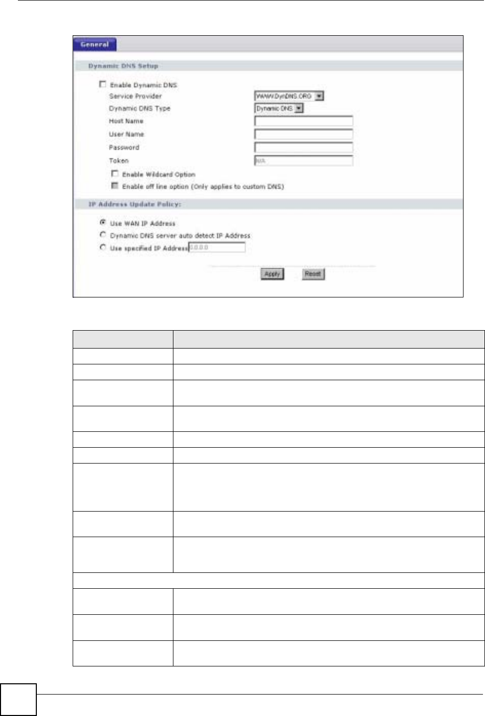
Chapter 12 Dynamic DNS
NBG-460N User’s Guide
148
Figure 95 Dynamic DNS
The following table describes the labels in this screen.
Table 56 Dynamic DNS
LABEL DESCRIPTION
Enable Dynamic DNS Select this check box to use dynamic DNS.
Service Provider Select the name of your Dynamic DNS service provider.
Dynamic DNS Type Select the type of service that you are registered for from your Dynamic DNS
service provider.
Host Name Enter a host names in the field provided. You can specify up to two host
names in the field separated by a comma (",").
User Name Enter your user name.
Password Enter the password assigned to you.
Token Enter your client authorization key provided by the server to update DynDNS
records.
This field is configurable only when you select WWW.REGFISH.COM in the
Service Provider field.
Enable Wildcard
Option Select the check box to enable DynDNS Wildcard.
Enable off line option This option is available when CustomDNS is selected in the DDNS Type
field. Check with your Dynamic DNS service provider to have traffic
redirected to a URL (that you can specify) while you are off line.
IP Address Update Policy:
Use WAN IP Address Select this option to update the IP address of the host name(s) to the WAN IP
address.
Dynamic DNS server
auto detect IP Address Select this option to update the IP address of the host name(s) automatically
by the DDNS server. It is recommended that you select this option.
Use specified IP
Address Type the IP address of the host name(s). Use this if you have a static IP
address.

Chapter 12 Dynamic DNS
NBG-460N User’s Guide 149
Apply Click Apply to save your changes back to the NBG-460N.
Reset Click Reset to begin configuring this screen afresh.
Table 56 Dynamic DNS
LABEL DESCRIPTION

Chapter 12 Dynamic DNS
NBG-460N User’s Guide
150