ads tec TT13C4 Diagnostic computer User Manual
ads-tec GmbH Diagnostic computer
UserManual.wiki
>
ads tec
>
TT13C4 User Manual
User Manual
Navigation menu
Upload a User Manual
Namespaces
Wiki Guide
HTML
PDF
Info
Views
User Manual
Discussion / Help
Navigation
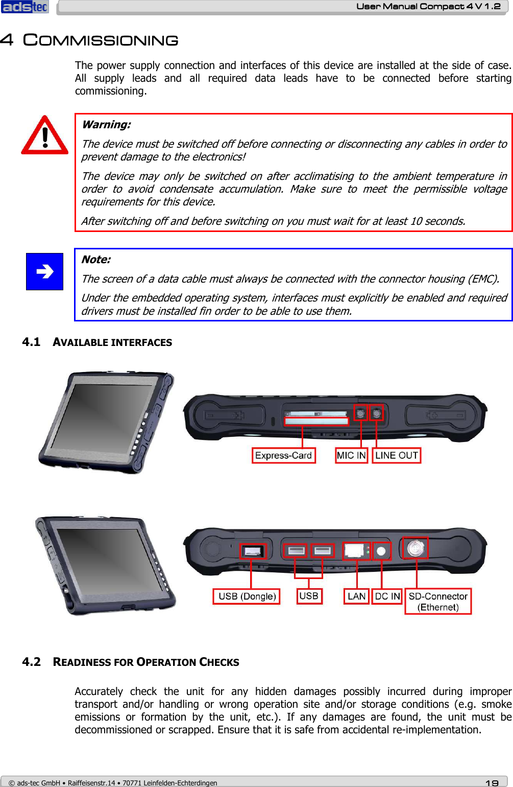
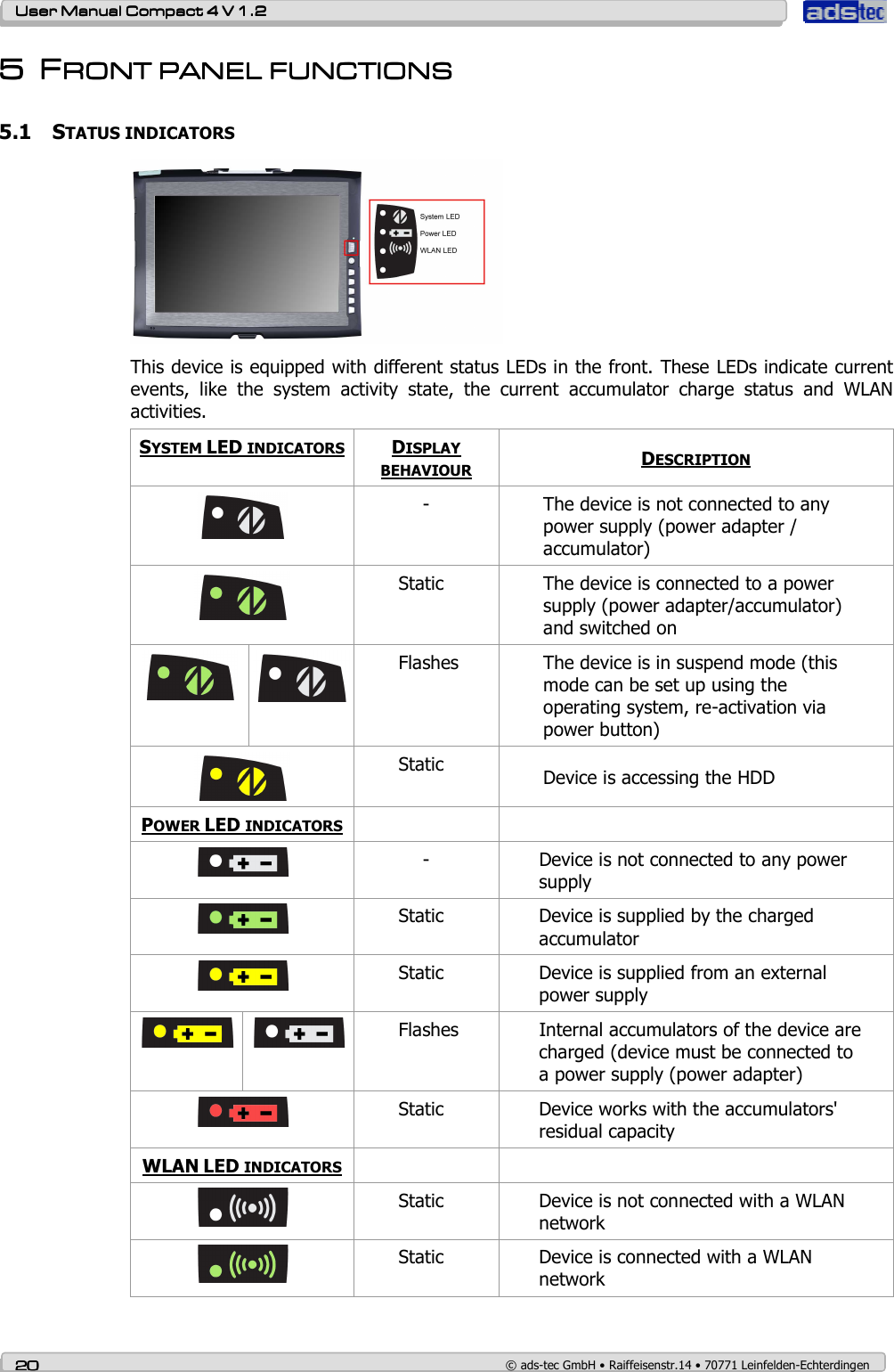
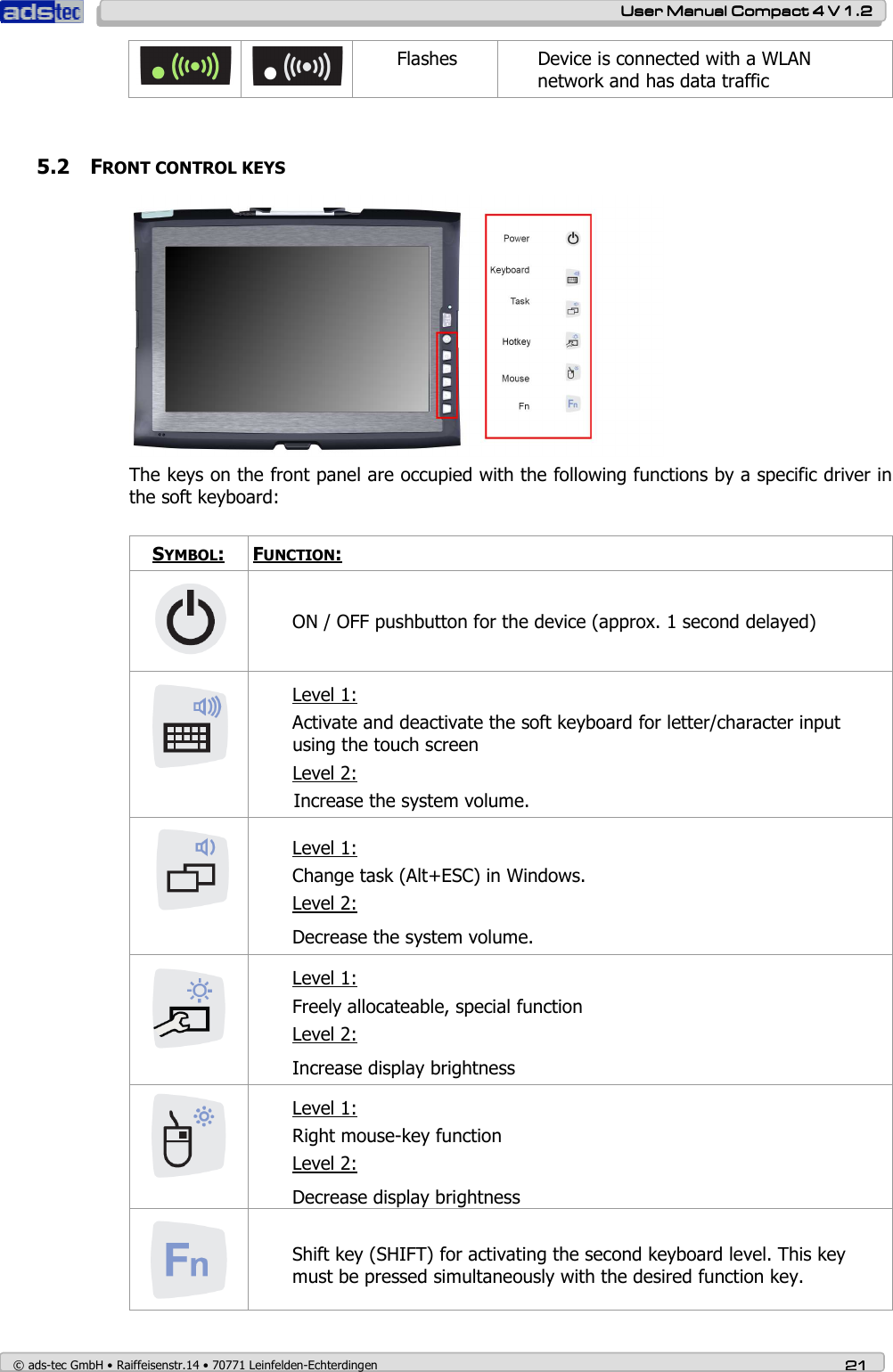
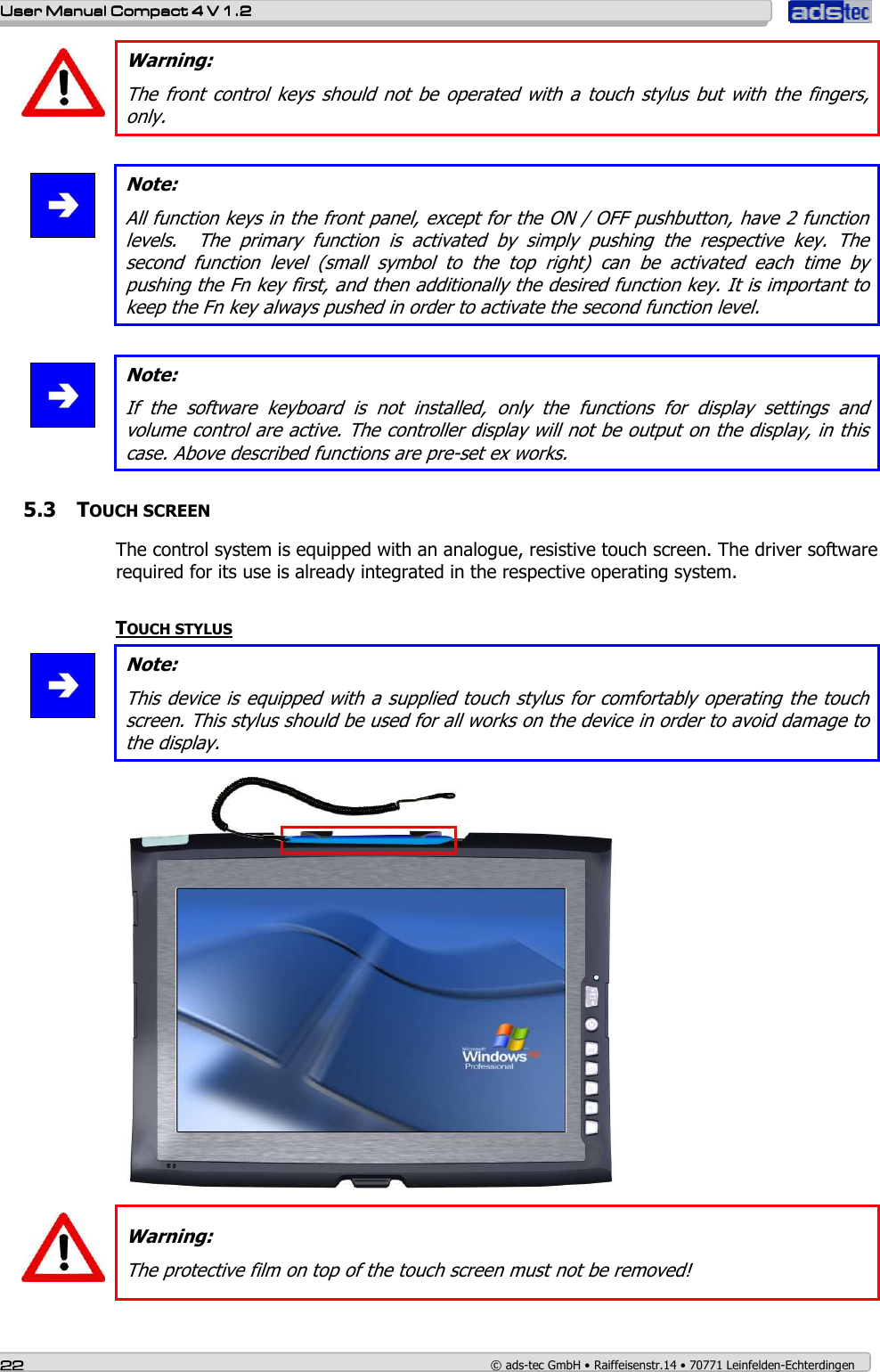
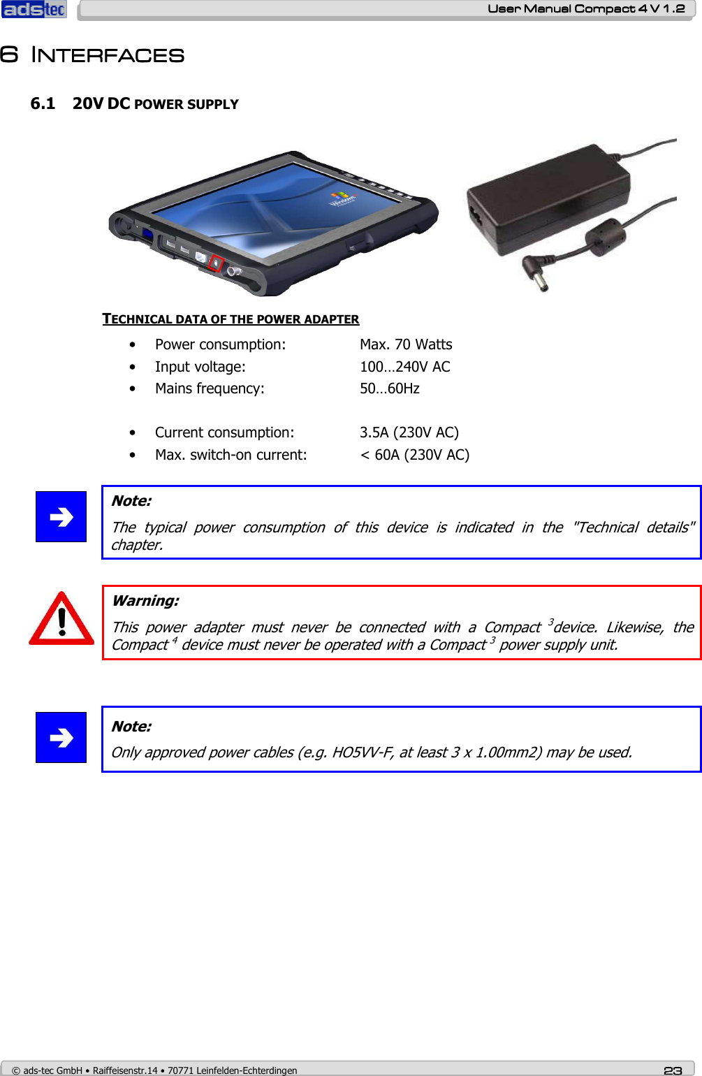
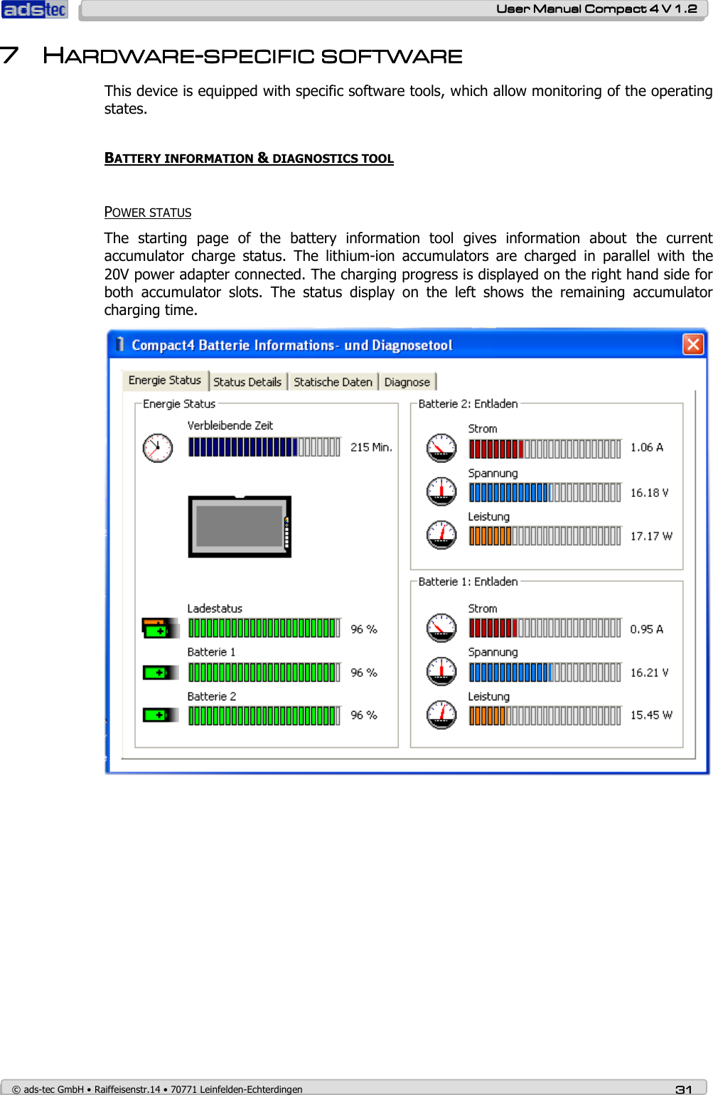
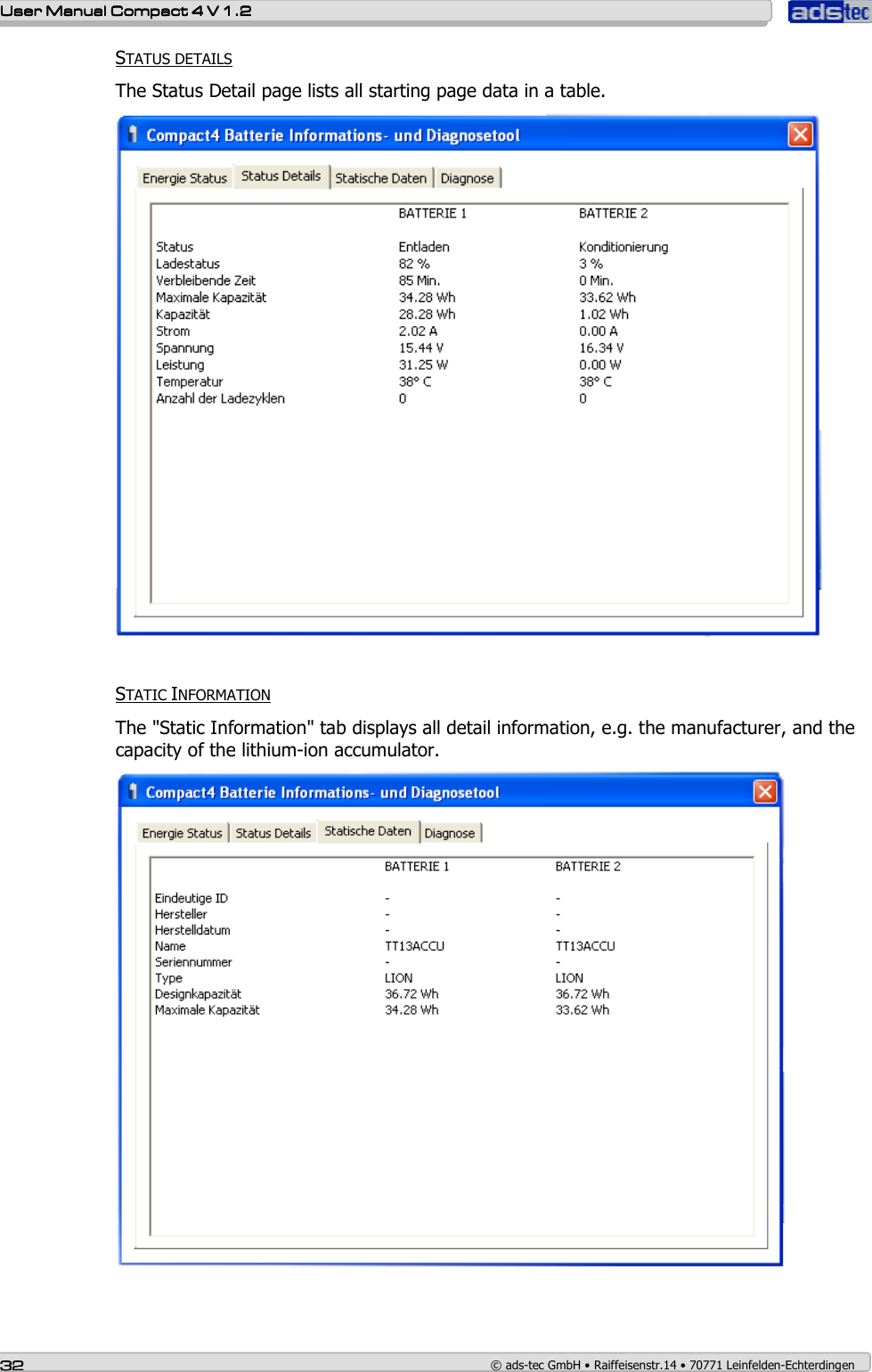
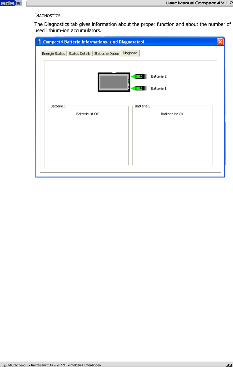
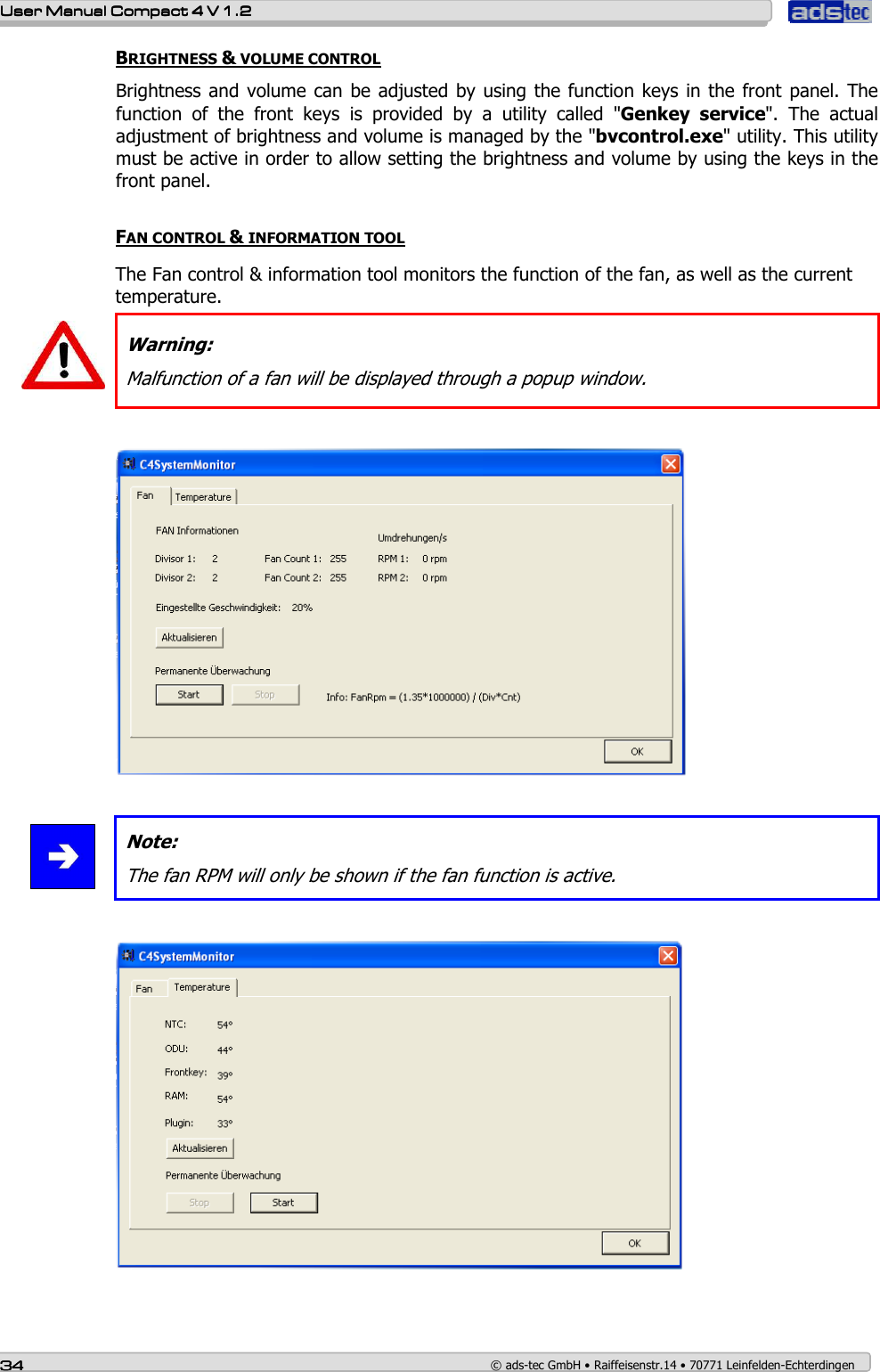

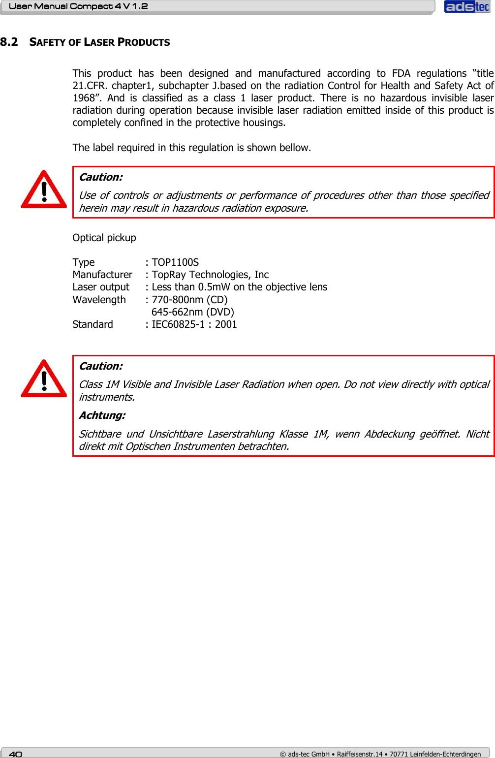
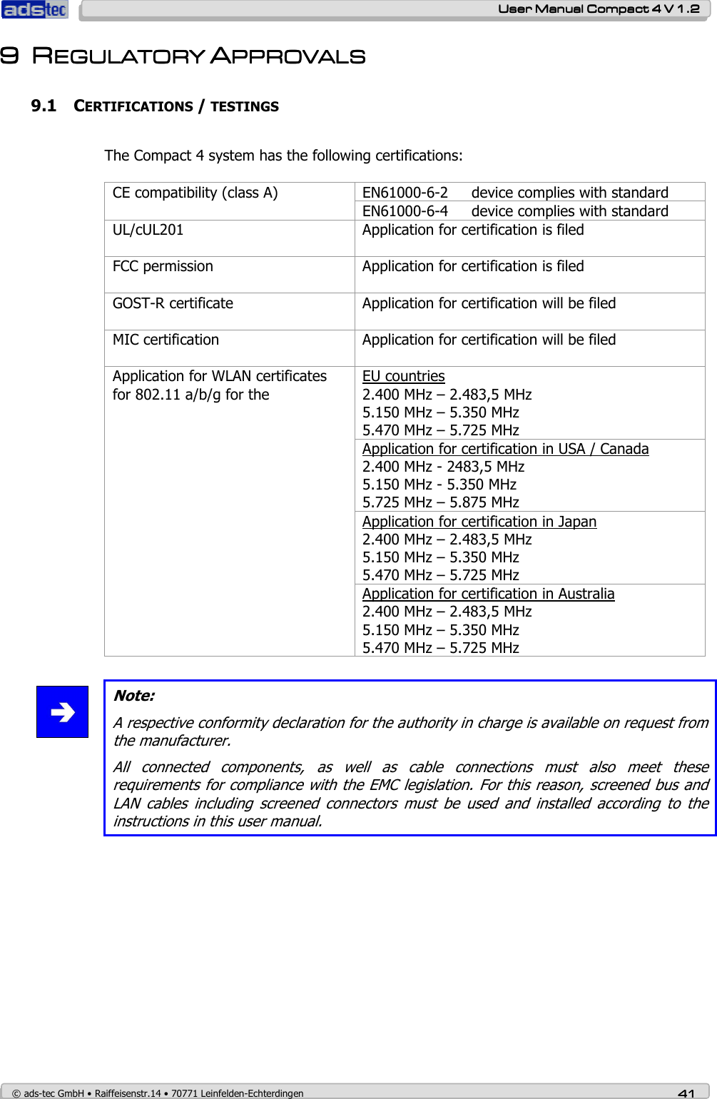
![User ManualUser ManualUser ManualUser Manual Compact 4 V 1.2Compact 4 V 1.2Compact 4 V 1.2Compact 4 V 1.2 © ads-tec GmbH • Raiffeisenstr.14 • 70771 Leinfelden-Echterdingen 43434343 9.3 FCC-APPROVAL Note: This device complies with Part 15 of the FCC Rules [and with RSS-210 of Industry Canada]. Operation is subject to the following two conditions: this device may not cause harmful interference, and this device must accept any interference received, including interference that may cause undesired operation. Note: Changes or modifications made to this equipment not expressly approved by ads-tec GmbH may void the FCC authorization to operate this equipment. Note: This equipment has been tested and found to comply with the limits for a Class A digital device, pursuant to Part 15 of the FCC Rules. These limits are designed to provide reasonable protection against harmful interference when the equipment is operated in a commercial environment. This equipment generates, uses, and can radiate radio frequency energy and, if not installed and used in accordance with the instruction manual, may cause harmful interference to radio communications. Operation of this equipment in a residential area is likely to cause harmful interference in which case the user will be required to correct the interference at his own expense. Note: Radiofrequency radiation exposure Information: This equipment complies with FCC radiation exposure limits set forth for an uncontrolled environment. This equipment should be installed and operated with minimum distance of 0cm between the radiator and your body. This transmitter must not be co-located or operating in conjunction with any other antenna or transmitter. Note: This Class A digital apparatus complies with Canadian ICES-003. Cet appareil numérique de la classe A est conforme à la norme NMB-003 du Canada.](https://usermanual.wiki/ads-tec/TT13C4/User-Guide-929760-Page-43.png)