User Manual

User Manual
User ManualUser Manual
User Manual
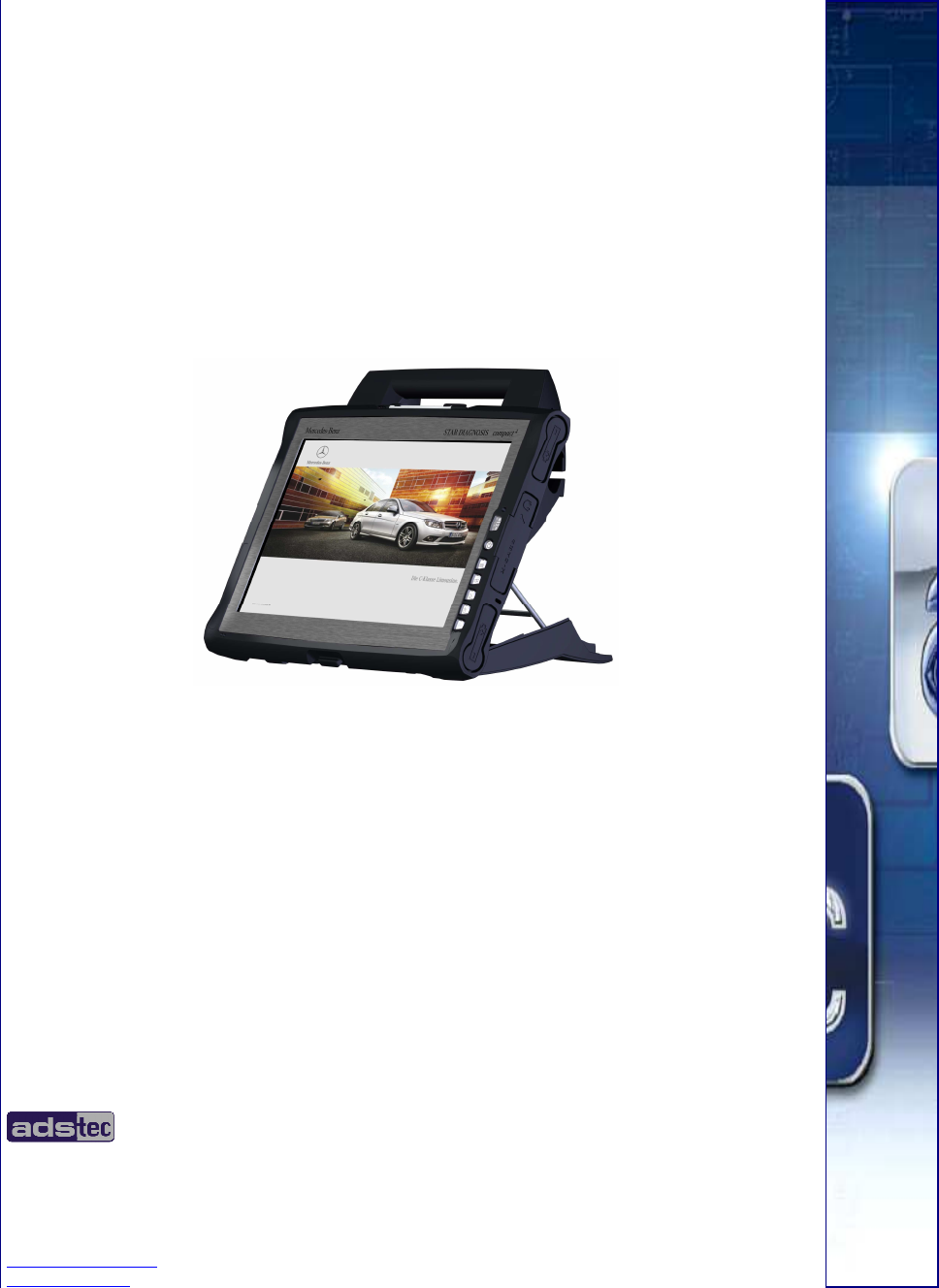
Compact 4 V 1.2
Compact 4 V 1.2Compact 4 V 1.2
Compact 4 V 1.2
2
22
2
© ads-tec GmbH • Raiffeisenstr.14 • 70771 Leinfelden-Echterdingen
Copyright
ads-tec GmbH
Raiffeisenstr.14
D-70771 Leinfelden-Echterdingen
Germany

User Manual
User ManualUser Manual
User Manual
Compact 4 V 1.2
Compact 4 V 1.2Compact 4 V 1.2
Compact 4 V 1.2
© ads-tec GmbH • Raiffeisenstr.14 • 70771 Leinfelden-Echterdingen 3
33
3
INDEX
ABOUT US.......................................................................................................................................... 5
1 REMARKS ................................................................................................................................. 6
1.1 RELEVANT DATA COMMUNICATION WITH THE DEVICE............................................................................ 6
1.2 DESCRIPTION OF THE WARNING SYMBOLS USED IN THIS GUIDE ............................................................... 6
1.3 DATA, IMAGES, AMENDMENTS AND VARIATIONS ................................................................................. 6
1.4 TRADEMARKS............................................................................................................................. 6
1.5 COPYRIGHT ............................................................................................................................... 7
1.6 ENVIRONMENTAL CONDITIONS........................................................................................................ 7
1.7 CERTIFICATIONS / TESTINGS.......................................................................................................... 8
1.8 SCOPE OF DELIVERY .................................................................................................................... 8
2 OPERATING INSTRUCTIONS ......................................................................................................... 9
2.1 OPERATING LOCATION ................................................................................................................. 9
2.2 DAMAGES DUE TO IMPROPER USE ................................................................................................... 9
2.3 WARRANTY / REPAIRS................................................................................................................ 10
2.4 HANDLING AND PROPER DISPOSAL OF LITHIUM BATTERIES ................................................................... 10
2.5 SAFETY INSTRUCTIONS............................................................................................................... 10
3 INSTALLATION ........................................................................................................................ 11
3.1 MULTIFUNCTION UNIT................................................................................................................ 11
3.2 INTERFACES OF THE COMPACT4 MULTIFUNCTION UNIT ........................................................................ 13
3.3 FUNCTIONS OF THE MULTIFUNCTION UNIT ....................................................................................... 16
3.4 EXTERNAL DEVICE DIMENSIONS .................................................................................................... 17
3.5 EXTERNAL DEVICE DIMENSIONS INCLUDING DOCKING STATION.............................................................. 18
4 COMMISSIONING..................................................................................................................... 19
4.1 AVAILABLE INTERFACES .............................................................................................................. 19
4.2 READINESS FOR OPERATION CHECKS ............................................................................................. 19
5 FRONT PANEL FUNCTIONS.......................................................................................................... 20
5.1 STATUS INDICATORS.................................................................................................................. 20
5.2 FRONT CONTROL KEYS................................................................................................................ 21
5.3 TOUCH SCREEN ........................................................................................................................ 22
6 INTERFACES............................................................................................................................ 23
6.1 20V DC POWER SUPPLY ............................................................................................................. 23
6.2 14.4V DC ACCUMULATOR OPERATING MODE.................................................................................... 24
6.3 USB CONNECTIONS ................................................................................................................... 26
6.4 SD CONNECTOR ....................................................................................................................... 27

User Manual
User ManualUser Manual
User Manual
Compact 4 V 1.2
Compact 4 V 1.2Compact 4 V 1.2
Compact 4 V 1.2
4
44
4
© ads-tec GmbH • Raiffeisenstr.14 • 70771 Leinfelden-Echterdingen
6.5 NETWORK CONNECTION (RJ45) ................................................................................................... 28
6.6 EXPRESSCARD SLOT .................................................................................................................. 28
6.7 MIC IN .................................................................................................................................. 29
6.8 LINE OUT................................................................................................................................ 30
6.9 WLAN................................................................................................................................... 30
7 HARDWARE-SPECIFIC SOFTWARE................................................................................................ 31
7.1 SOFT KEYBOARD ....................................................................................................................... 37
8 ACCESSORIES.......................................................................................................................... 39
8.1 DVD DRIVE / EXTERNAL TYPE ...................................................................................................... 39
8.2 SAFETY OF LASER PRODUCTS ....................................................................................................... 40
9 REGULATORY APPROVALS ......................................................................................................... 41
9.1 CERTIFICATIONS / TESTINGS........................................................................................................ 41
9.2 ELECTROMAGNETIC COMPATIBILITY (EMC)...................................................................................... 42
9.3 FCC-APPROVAL........................................................................................................................ 43
10 TECHNICAL DETAILS ................................................................................................................. 44
10.1 DISPLAY DATA.......................................................................................................................... 44
10.2 COMPUTER DATA ...................................................................................................................... 44
10.3 GENERAL DATA......................................................................................................................... 44
11 SERVICE AND SUPPORT............................................................................................................. 45
11.1 ADS-TEC SUPPORT .................................................................................................................... 45
11.2 COMPANY ADDRESS................................................................................................................... 45
User Manual
User ManualUser Manual
User Manual
Compact 4 V 1.2
Compact 4 V 1.2Compact 4 V 1.2
Compact 4 V 1.2
© ads-tec GmbH • Raiffeisenstr.14 • 70771 Leinfelden-Echterdingen 5
55
5
A
AA
ABOUT US
BOUT USBOUT US
BOUT US
ads-tec GmbH
Raiffeisenstr. 14
70771 Leinfelden-Echterdingen
Tel: +49 (0) 711 / 45894-0
Fax: +49 (0) 711 / 45894-990
www.ads-tec.com
Germany
ads-tec GmbH provides large enterprises and globally active corporations with cutting edge
technology, up-to-date know-how and comprehensive services in the area of automation
technology, data processing technology and systems engineering.
ads-tec GmbH implements full automation solutions from planning to commissioning and is
specialized in handling and material handling technologies.
The data systems division develops and produces PC based solutions and offers a broad
range of industrial PCs, thin clients and embedded systems.
ads-tec is specialized in modifying and optimizing embedded operating systems and
develops software tools to complement its hardware platforms.
User Manual
User ManualUser Manual
User Manual
Compact 4 V 1.2
Compact 4 V 1.2Compact 4 V 1.2
Compact 4 V 1.2
6
66
6
© ads-tec GmbH • Raiffeisenstr.14 • 70771 Leinfelden-Echterdingen
1
11
1 R
RR
REMARKS
EMARKSEMARKS
EMARKS
1.1 RELEVANT DATA COMMUNICATION WITH THE DEVICE
The following documents are essential for setting up and operating this device:
USER MANUAL:
Contains information for installation, commissioning and operating the device along with
technical data of the device hardware.
a
1.2 DESCRIPTION OF THE WARNING SYMBOLS USED IN THIS GUIDE
Warning:
The “Warning” symbol precedes warnings on uses or operations that might either lead to
personal injury and/or hazards, or to any hardware and software damages.
Note:
This Symbol indicates special notes, terms and/or conditions that strictly need to be
observed to ensure optimised and/or zero-defect operations. It also precedes tips and
suggestions for efficient unit implementation and software optimisation.
1.3 DATA, IMAGES, AMENDMENTS AND VARIATIONS
The texts, data and images herein are not binding. The right to any subsequent amendment
and/or variation due to any technical and engineering progresses in the art whatsoever is
hereby reserved.
1.4 TRADEMARKS
It is hereby notified that any software and/or hardware trademarks further to any company
brand names as mentioned in this User’s Guide are all strictly subject to the various
trademark, brand name and patent protection rights.
WINDOWS®, WINDOWS® CE and WINDOWS® CE.net™ are registered trademarks of
Microsoft Corp.
Citrix® and ICA® are registered trademarks of Citrix Systems Inc.
Intel® and Pentium® are registered trademarks of Intel Corp.
IBM®, PS/2® and VGA® are registered trademarks of IBM Corp.
CompactFlash™ and CF™ are registered trademarks of SanDisk Corp.
Any further additional trademarks and/or brand names herein, be they domestic or
international, are hereby duly acknowledged.

User Manual
User ManualUser Manual
User Manual
Compact 4 V 1.2
Compact 4 V 1.2Compact 4 V 1.2
Compact 4 V 1.2
© ads-tec GmbH • Raiffeisenstr.14 • 70771 Leinfelden-Echterdingen 7
77
7
1.5 COPYRIGHT
This User’s Guide inclusive of all the images it contains is entirely proprietary and subject to
copyright. Any irregular use of this Guide by third parties infringing copyright terms is thus
strictly forbidden. Reproduction, translation, as well as electronic and photographic image
storage and/or amendment processes, are subject to prior written authorisation directly by
M/s. ads-tec GmbH.
Any violation and infringement thereto will be held liable for compensation of all damages.
1.6 ENVIRONMENTAL CONDITIONS
The device may be operated under the following conditions. Failure to observe these
specifications will terminate any warranty for this device. Ads-tec cannot be held liable for
any damages arising due to improper use and handling.
• Temperature with fan
In operation 0 … 40 C
For storage -20 … 60 C
(Because of the integrated maximum temperature memory)
• Humidity
In operation 10 … 85% without any condensate
For storage 10 … 85% without any condensate
• Vibrations
In operation MIL-STD-810F acc to method 514.5, figure C1
• Shock resistance
In operation 15 G, with a half-wave of 11 ms duration
(DIN EN 60068-2-27)
User Manual
User ManualUser Manual
User Manual
Compact 4 V 1.2
Compact 4 V 1.2Compact 4 V 1.2
Compact 4 V 1.2
8
88
8
© ads-tec GmbH • Raiffeisenstr.14 • 70771 Leinfelden-Echterdingen
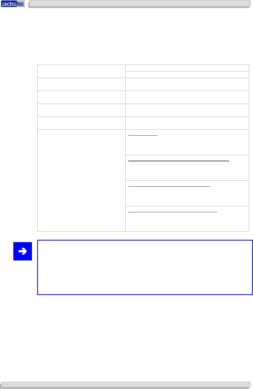
1.7 CERTIFICATIONS / TESTINGS
The Compact 4 system has the following certifications:
EN61000-6-2 device complies with standard CE compatibility (class A)
EN61000-6-4 device complies with standard
UL/cUL201
Application for certification is filed
FCC permission
Application for certification is filed
GOST-R certificate
Application for certification will be filed
MIC certification
Application for certification will be filed
EU countries
2.400 MHz – 2.483,5 MHz
5.150 MHz – 5.350 MHz
5.470 MHz – 5.725 MHz
Application for certification in USA / Canada
2.400 MHz - 2483,5 MHz
5.150 MHz - 5.350 MHz
5.725 MHz – 5.875 MHz
Application for certification in Japan
2.400 MHz – 2.483,5 MHz
5.150 MHz – 5.350 MHz
5.470 MHz – 5.725 MHz
Application for WLAN certificates
for 802.11 a/b/g
Application for certification in Australia
2.400 MHz – 2.483,5 MHz
5.150 MHz – 5.350 MHz
5.470 MHz – 5.725 MHz
Note:
A respective conformity declaration for the authority in charge is available on request from
the manufacturer.
All connected components, as well as cable connections must also meet these
requirements for compliance with the EMC legislation. For this reason, screened bus and
LAN cables including screened connectors must be used and installed according to the
instructions in this user manual.
1.8 SCOPE OF DELIVERY
The following components are included in the scope of delivery:
• 1 x device
• 1 x transport case
• 1 x 20V DC power supply unit
• 1 x multiplex adapter
• 1 x multifunctional unit
• 1 x DVD drive, external
User Manual
User ManualUser Manual
User Manual
Compact 4 V 1.2
Compact 4 V 1.2Compact 4 V 1.2
Compact 4 V 1.2
© ads-tec GmbH • Raiffeisenstr.14 • 70771 Leinfelden-Echterdingen 9
99
9
2
22
2 O
OO
OPERATING INSTRUCTION
PERATING INSTRUCTIONPERATING INSTRUCTION
PERATING INSTRUCTIONS
SS
S
This device contains electrical voltages and extremely sensitive components. The
manufacturer, or a service partner authorised by the manufacturer, should be consulted if
you plan to make any modifications. For this type of work, the device must be switched off
at the mains and the power lead must be disconnected. Suitable measures for avoiding
electrostatic discharge towards parts of the components when touching the equipment must
be taken. If the device is opened by an unauthorised person, hazards for the user might
arise and any warranty claim will cease.
General instructions:
• All users must read this manual and have access to it at all times.
• Installation, commissioning and operation may only be carried out by trained and
qualified staff.
• The security instructions and the manual itself must be observed by all persons who
work with this device.
• At the location of use the valid guidelines and regulations for accident prevention
must be observed.
• The manual contains the most important instructions on how to use this device in a
safe way.
• Appropriate storage, proper transport, installation and commissioning, as well as
careful operation are prerequisites for ensuring safe and proper operation of the
device.
Warning:
Any leads (e.g. power leads, interface cables) may only be connected if the device is
switched off in order to avoid damaging the device.
2.1 OPERATING LOCATION
This device is designed for use in industry, in particular in workshops. You have to take care
that the environmental conditions indicated in the technical data specification are met. Using
the device in non-specified environments, for example, on board ships, or in areas that
might contain explosive gases or in extreme heights is prohibited.
Warning:
The device may only be switched on after acclimatising to the ambient temperature in
order to avoid condensate accumulation. The same applies if the device has previously
been exposed to extreme temperature variations.
To avoid overheating: The device must not be exposed to direct radiation by sunlight or
any other light or heat source.
2.2 DAMAGES DUE TO IMPROPER USE
Should the service system have evident signs of damages incurred e.g. due to wrong
operation or storage conditions or due to improper unit use, the unit must be
decommissioned or scrapped. Ensure that it is safe from accidental re-implementation.
User Manual
User ManualUser Manual
User Manual
Compact 4 V 1.2
Compact 4 V 1.2Compact 4 V 1.2
Compact 4 V 1.2
10
1010
10
© ads-tec GmbH • Raiffeisenstr.14 • 70771 Leinfelden-Echterdingen
2.3 WARRANTY / REPAIRS
During the unit warranty period, any repairs thereto must strictly be conducted solely by the
manufacturer or by service personnel that has been duly authorised by the manufacturer.
2.4 HANDLING AND PROPER DISPOSAL OF LITHIUM BATTERIES
Caution:
Danger of explosion and the release of toxic substances
Lithium batteries should not be exposed to fire, soldered, recharged, opened, short-
circuited, reversed or heated above 100 °C and they should be disposed of properly as well
as protected against sunlight, moisture and condensation.
The lithium battery can only be replaced by the same type or a type recommended by the
manufacturer.
The used lithium battery should be disposed of in accordance with local legal regulations.
2.5 SAFETY INSTRUCTIONS
Warning:
All unit assembly operations must be strictly conducted only under safe, secure and zero-
potential conditions.
Special Note:
When handling parts and components susceptible to electrical discharge, please
accurately observe all the relevant safety provisions.
(DIN EN 61340-5-1 / DIN EN 61340-5-2 refers)
User Manual
User ManualUser Manual
User Manual
Compact 4 V 1.2
Compact 4 V 1.2Compact 4 V 1.2
Compact 4 V 1.2
© ads-tec GmbH • Raiffeisenstr.14 • 70771 Leinfelden-Echterdingen 11
1111
11
3
33
3 I
II
INSTALLATION
NSTALLATIONNSTALLATION
NSTALLATION
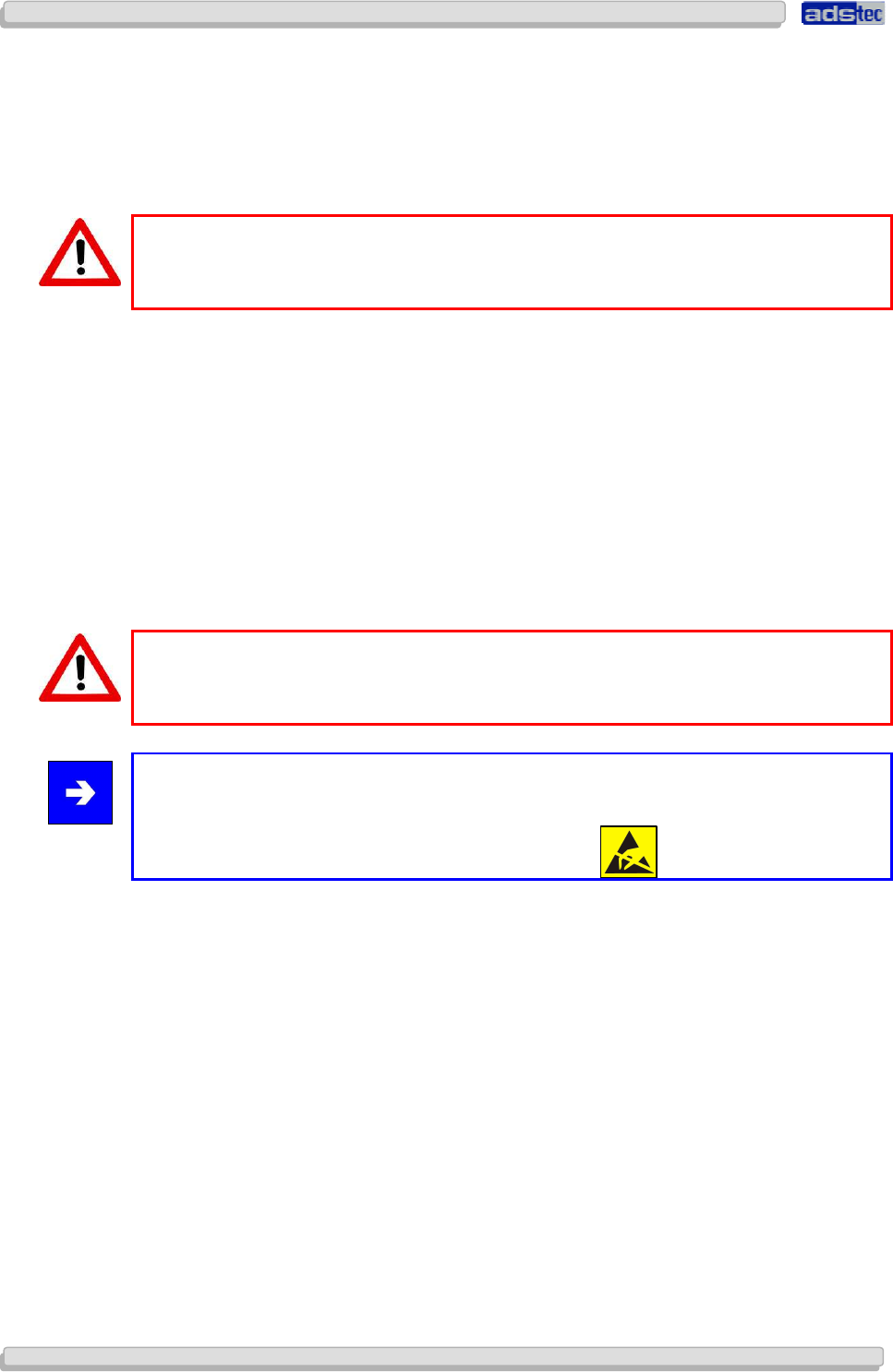
3.1 MULTIFUNCTION UNIT
The device may be connected to a multifunction unit on the back by using a docking
interface.
INSTALLING THE MULTIFUNCTION UNIT
Pay attention when attaching the device on top of the multifunction unit, that the docking
plug, and the docking socket located at the Compact4 device, are safely connected with
each other. Make sure that the Compact4 device is properly attached to the multifunction
unit. (Figure 3)
User Manual
User ManualUser Manual
User Manual
Compact 4 V 1.2
Compact 4 V 1.2Compact 4 V 1.2
Compact 4 V 1.2
12
1212
12
© ads-tec GmbH • Raiffeisenstr.14 • 70771 Leinfelden-Echterdingen
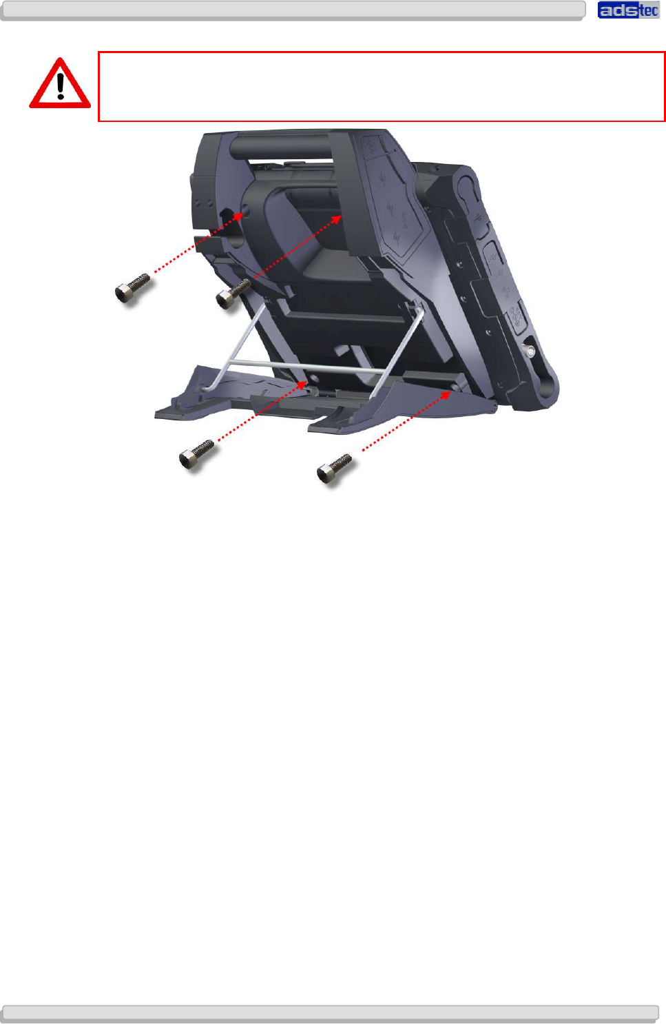
Warning:
If this device is to be used in connection with a multifunction unit, the supplied screws
must be used in order to tightly connect the device to it.
The supplied type of screws is 4 x DIN 7984 M5 x 5, black.
User Manual
User ManualUser Manual
User Manual
Compact 4 V 1.2
Compact 4 V 1.2Compact 4 V 1.2
Compact 4 V 1.2
© ads-tec GmbH • Raiffeisenstr.14 • 70771 Leinfelden-Echterdingen 13
1313
13
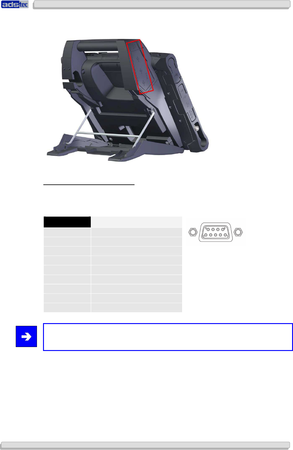
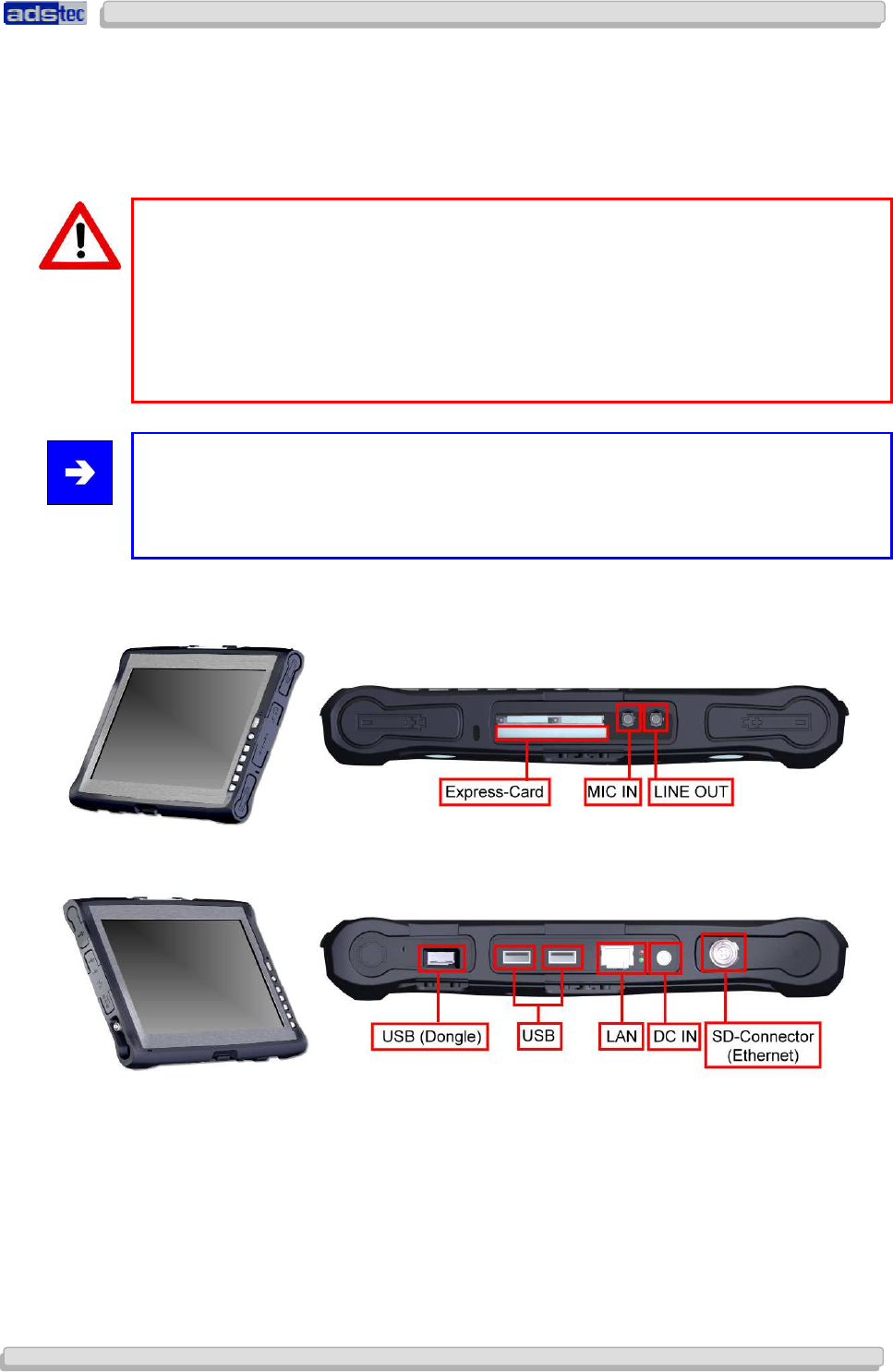
3.2 INTERFACES OF THE COMPACT4 MULTIFUNCTION UNIT
COM SERIAL INTERFACE (RS 232)
The serial interface is also used for digital and analogue data transmission. The RS 232
interface can be connected by using a commercially available 9-pin SUB-D cable.
PIN NUMBER SIGNAL NAME
1 DCD
2 RxD
3 TxD
4 DTR
5 GND
6 DSR
7 RTS
8 CTS
9 RI
Note:
This interface is not electrically isolated.
User Manual
User ManualUser Manual
User Manual
Compact 4 V 1.2
Compact 4 V 1.2Compact 4 V 1.2
Compact 4 V 1.2
14
1414
14
© ads-tec GmbH • Raiffeisenstr.14 • 70771 Leinfelden-Echterdingen
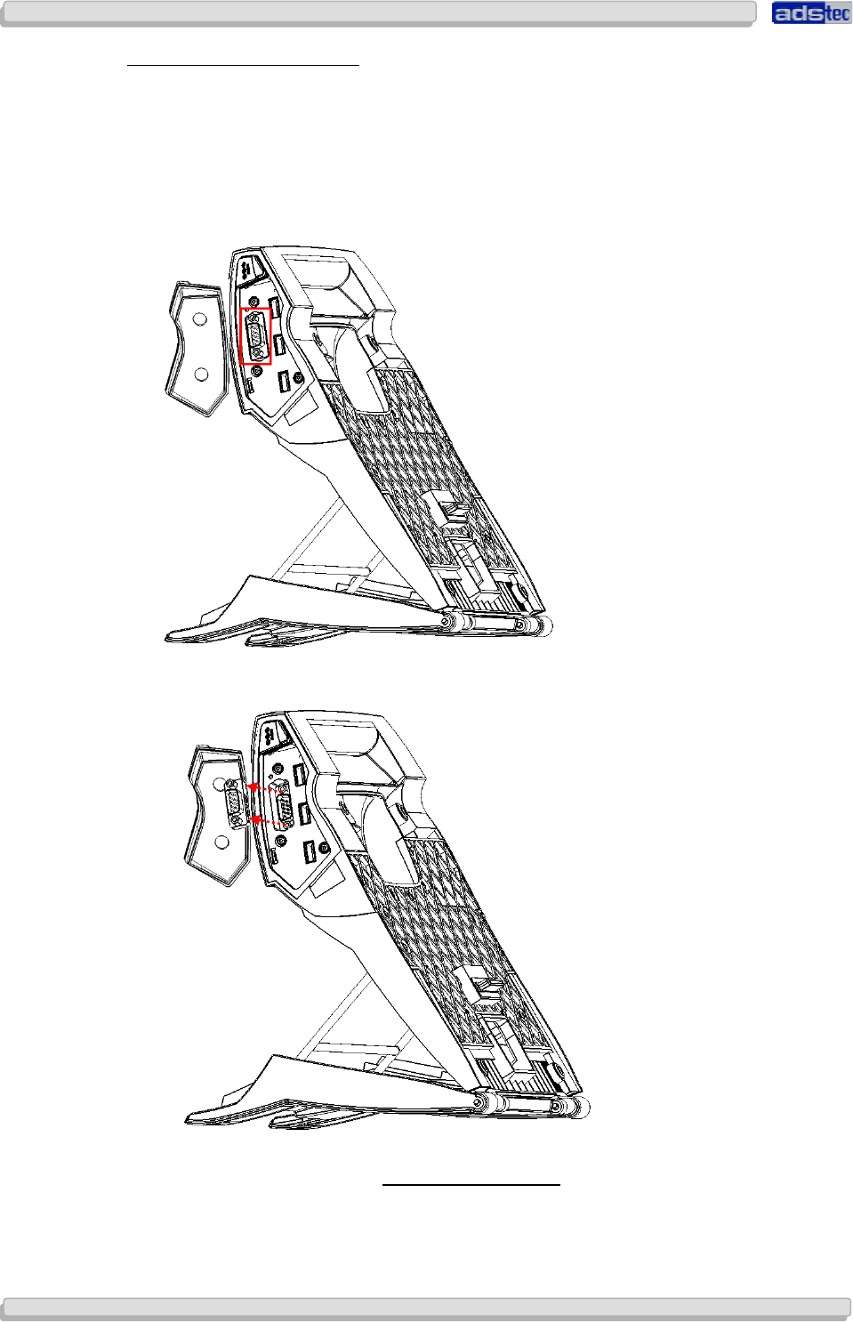
CHANGING THE COM ADAPTER
The COM interface is equipped with an attached adapter (gender changer) in order to avoid
damage to the COM interface. You can replace this adapter, should it be damaged. Please
proceed as follows in order to replace the adapter:
1) Open the rubber cover of the Compact4 multifunction unit and subsequently loosen both
SUB-D bolts by using a suitable screw driver or socket wrench...
2) Once both SUB-D bolts are removed, the adapter (gender changer) can be pulled off.
3) Attach the new adapter to the COM interface. Tighten both
SUB-D bolts with a torque of NCM TO BE DEFINED and close the rubber cover.
User Manual
User ManualUser Manual
User Manual
Compact 4 V 1.2
Compact 4 V 1.2Compact 4 V 1.2
Compact 4 V 1.2
© ads-tec GmbH • Raiffeisenstr.14 • 70771 Leinfelden-Echterdingen 15
1515
15
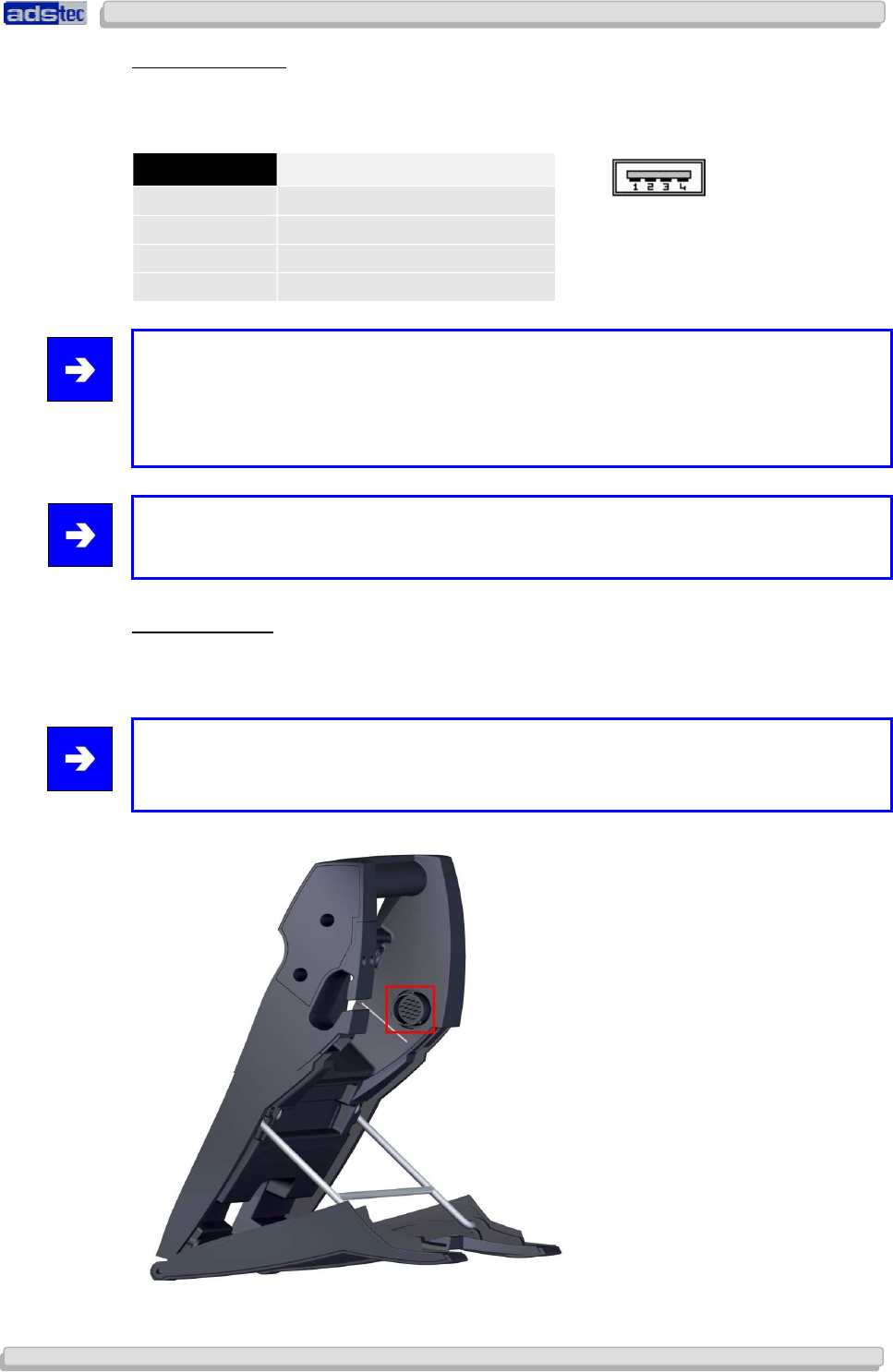
USB CONNECTIONS
The USB interfaces are used for connecting peripherals with USB connection. The interface
complies with the USB 2.0 standard.
PIN NUMBER SIGNAL NAME
1 VDC
2 D -
3 D+
4 GND
Note:
The three available USB interfaces give you the opportunity for a voltage output of 1.5V
on one of the USB interfaces at a time. This allows trouble-free operation of external
devices, like an external DVD drive. Both remaining ports output a voltage of 0.5V by
default in this case.
Note:
This interface is not electrically isolated.
MIL CONNECTOR:
The docking station is equipped with a MIL connector. This type of connector is used in
automotive industry, specifically in vehicle diagnostics. By using specific software, it allows
extracting and analysing data from the vehicle.
Note:
If the device is connected to a passenger car via the multifunction unit, the device can be
supplied with the required voltage from the vehicle.
User Manual
User ManualUser Manual
User Manual
Compact 4 V 1.2
Compact 4 V 1.2Compact 4 V 1.2
Compact 4 V 1.2
16
1616
16
© ads-tec GmbH • Raiffeisenstr.14 • 70771 Leinfelden-Echterdingen
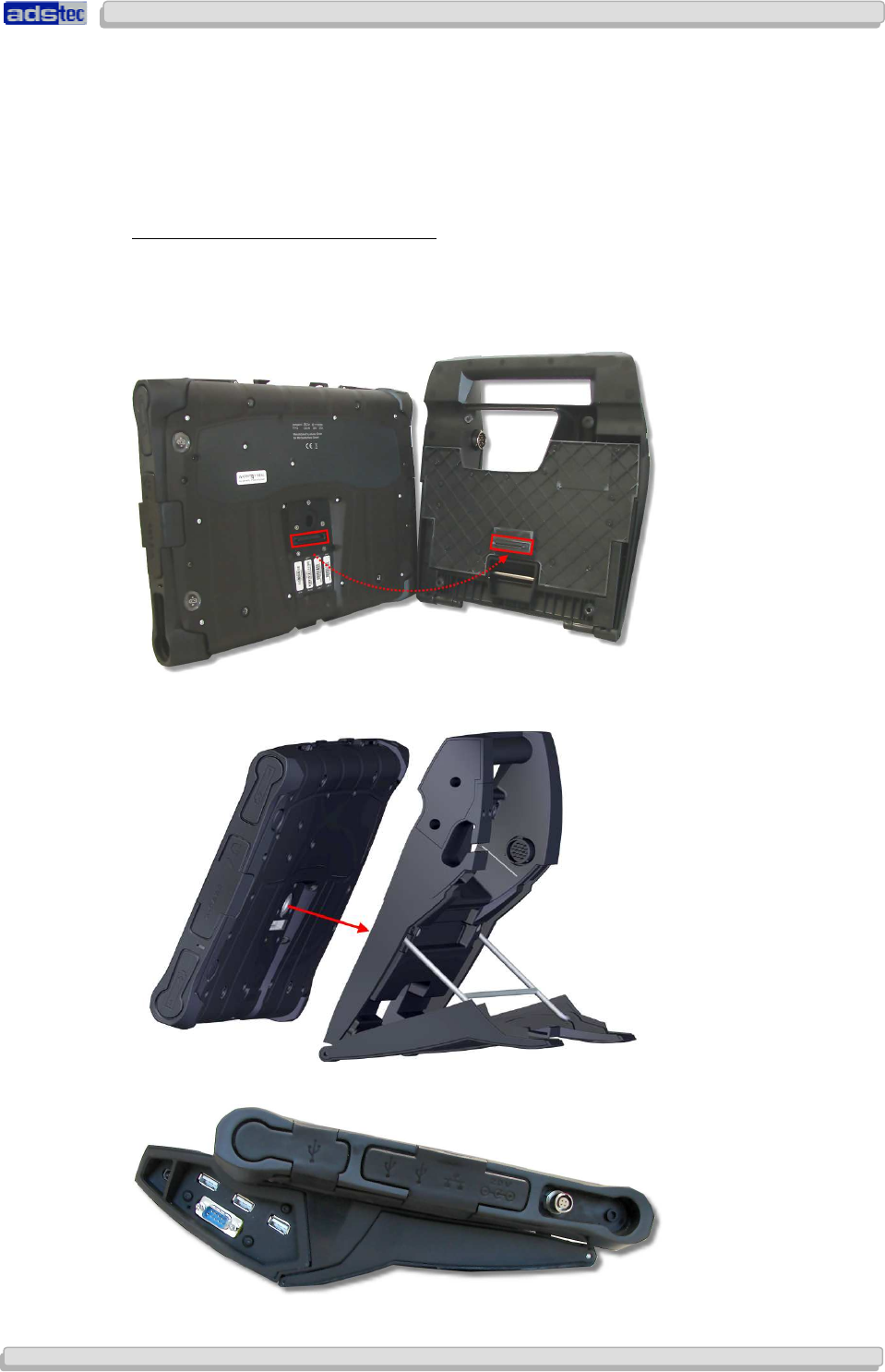
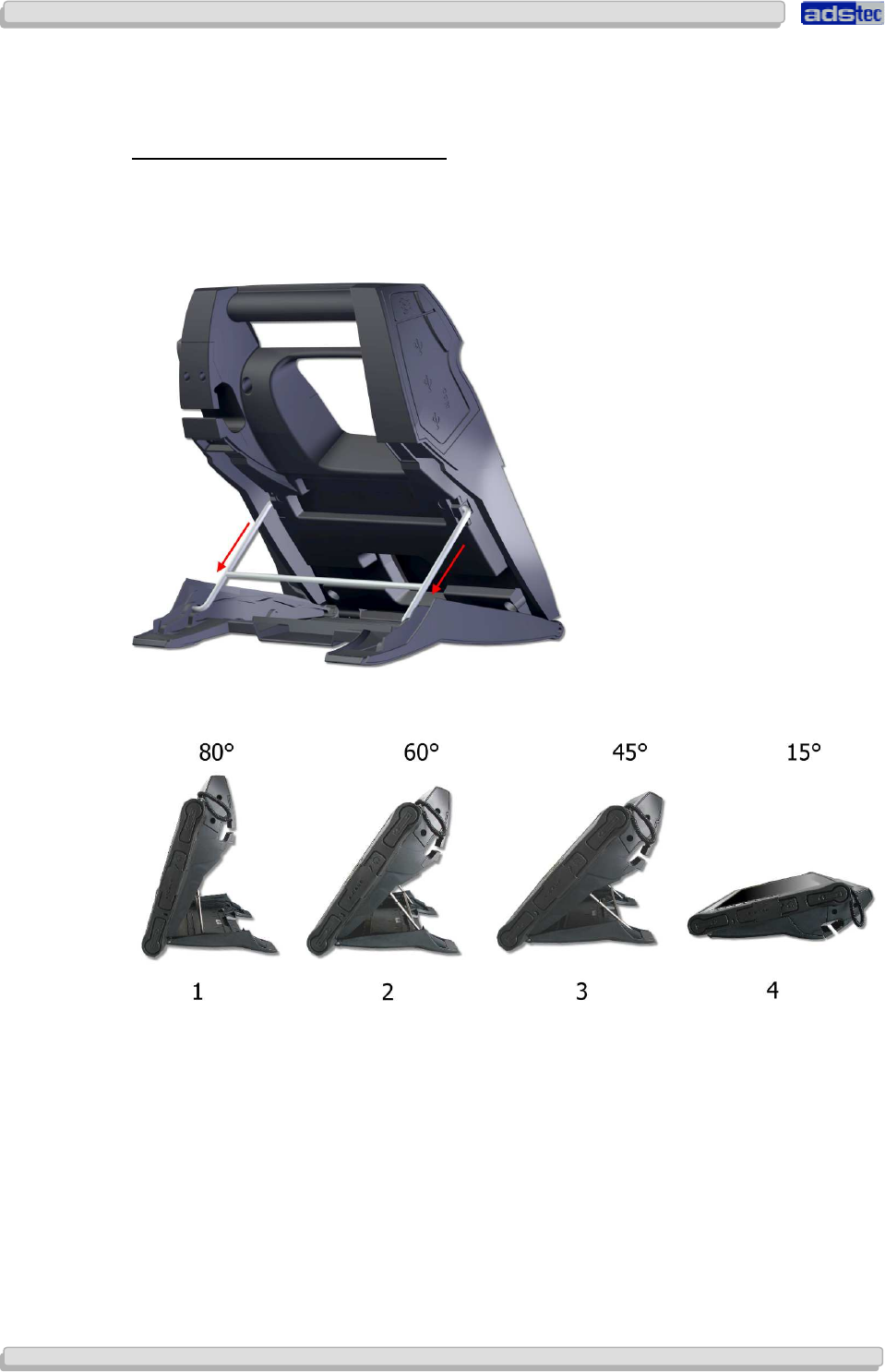
3.3 FUNCTIONS OF THE MULTIFUNCTION UNIT
ADJUSTABLE POSITIONING MECHANISM:
The viewing angle of the docking station can be adjusted by using the positioning
mechanism.
The positioning mechanism may be fixed in several notch positions at the multifunction unit.
User Manual
User ManualUser Manual
User Manual
Compact 4 V 1.2
Compact 4 V 1.2Compact 4 V 1.2
Compact 4 V 1.2
© ads-tec GmbH • Raiffeisenstr.14 • 70771 Leinfelden-Echterdingen 17
1717
17
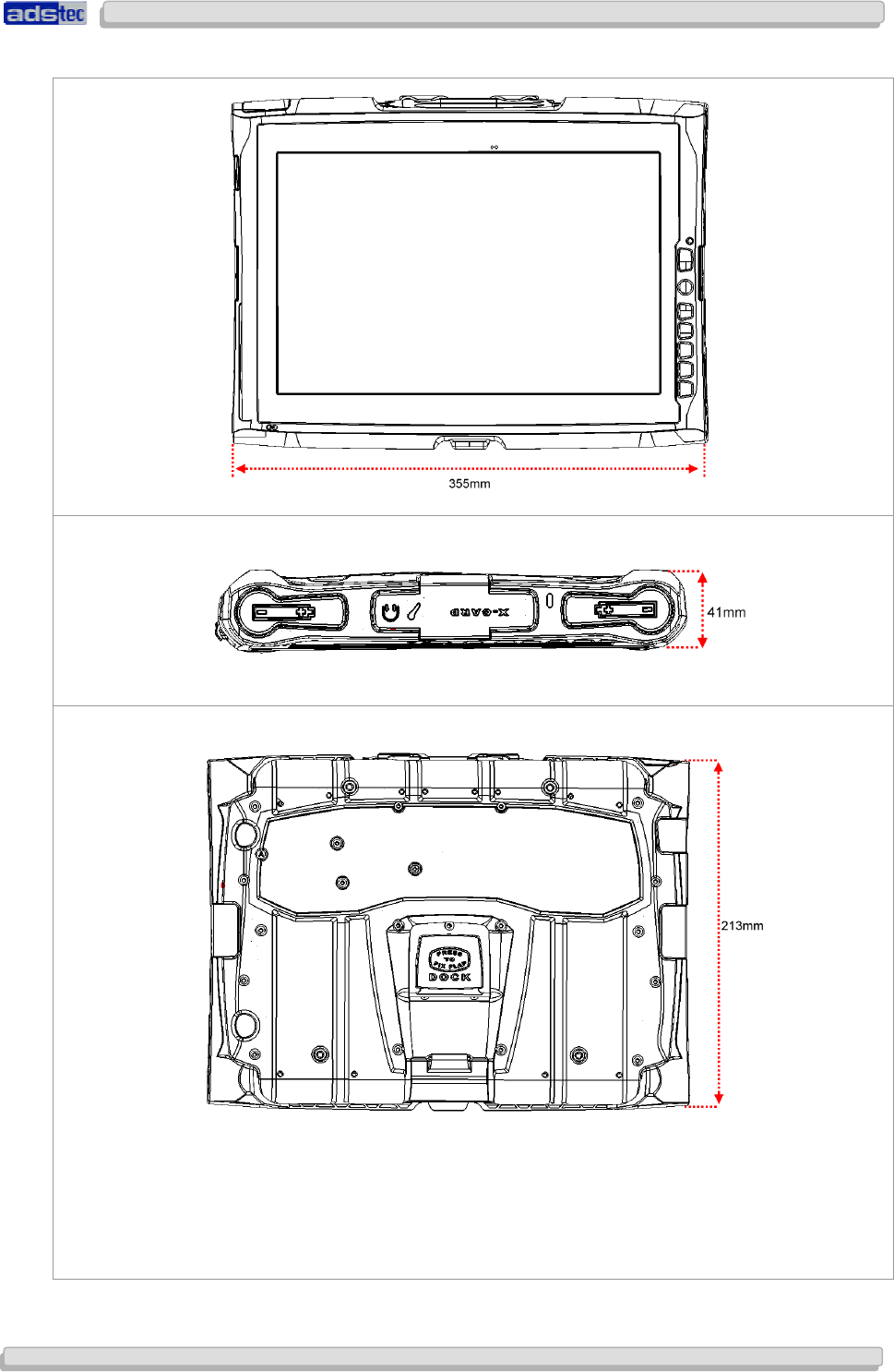
3.4 EXTERNAL DEVICE DIMENSIONS
User Manual
User ManualUser Manual
User Manual
Compact 4 V 1.2
Compact 4 V 1.2Compact 4 V 1.2
Compact 4 V 1.2
18
1818
18
© ads-tec GmbH • Raiffeisenstr.14 • 70771 Leinfelden-Echterdingen
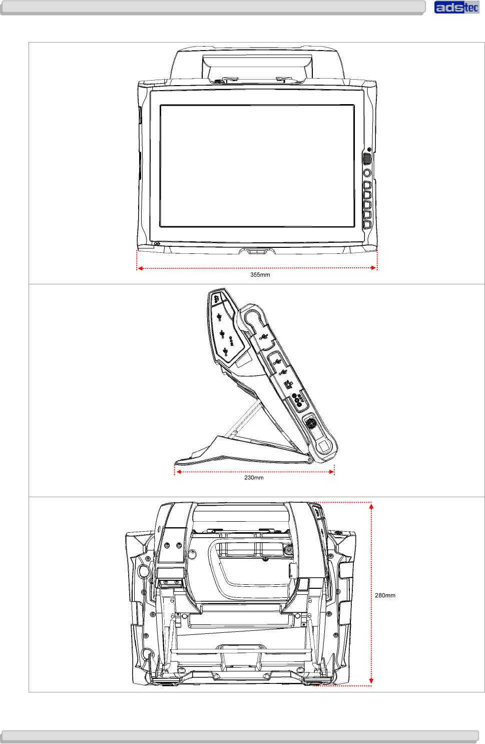
3.5 EXTERNAL DEVICE DIMENSIONS INCLUDING DOCKING STATION
User Manual
User ManualUser Manual
User Manual
Compact 4 V 1.2
Compact 4 V 1.2Compact 4 V 1.2
Compact 4 V 1.2
© ads-tec GmbH • Raiffeisenstr.14 • 70771 Leinfelden-Echterdingen 19
1919
19
4
44
4 C
CC
COMMISSIONING
OMMISSIONINGOMMISSIONING
OMMISSIONING
The power supply connection and interfaces of this device are installed at the side of case.
All supply leads and all required data leads have to be connected before starting
commissioning.
Warning:
The device must be switched off before connecting or disconnecting any cables in order to
prevent damage to the electronics!
The device may only be switched on after acclimatising to the ambient temperature in
order to avoid condensate accumulation. Make sure to meet the permissible voltage
requirements for this device.
After switching off and before switching on you must wait for at least 10 seconds.
Note:
The screen of a data cable must always be connected with the connector housing (EMC).
Under the embedded operating system, interfaces must explicitly be enabled and required
drivers must be installed fin order to be able to use them.
4.1 AVAILABLE INTERFACES
4.2 READINESS FOR OPERATION CHECKS
Accurately check the unit for any hidden damages possibly incurred during improper
transport and/or handling or wrong operation site and/or storage conditions (e.g. smoke
emissions or formation by the unit, etc.). If any damages are found, the unit must be
decommissioned or scrapped. Ensure that it is safe from accidental re-implementation.
User Manual
User ManualUser Manual
User Manual
Compact 4 V 1.2
Compact 4 V 1.2Compact 4 V 1.2
Compact 4 V 1.2
20
2020
20
© ads-tec GmbH • Raiffeisenstr.14 • 70771 Leinfelden-Echterdingen
5
55
5 F
FF
FRONT PANEL FUNCTIONS
RONT PANEL FUNCTIONSRONT PANEL FUNCTIONS
RONT PANEL FUNCTIONS
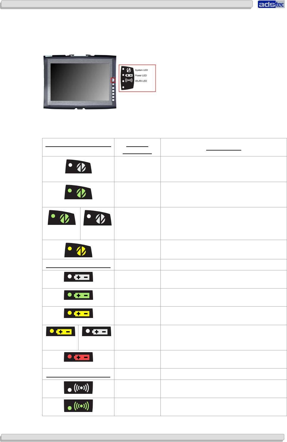
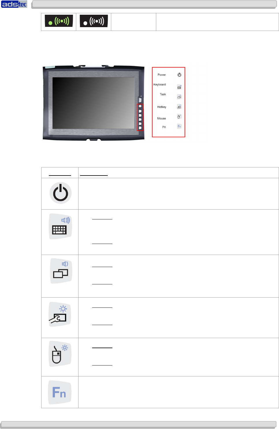
5.1 STATUS INDICATORS
This device is equipped with different status LEDs in the front. These LEDs indicate current
events, like the system activity state, the current accumulator charge status and WLAN
activities.
SYSTEM LED INDICATORS
DISPLAY
BEHAVIOUR DESCRIPTION
- The device is not connected to any
power supply (power adapter /
accumulator)
Static The device is connected to a power
supply (power adapter/accumulator)
and switched on
Flashes The device is in suspend mode (this
mode can be set up using the
operating system, re-activation via
power button)
Static Device is accessing the HDD
POWER LED INDICATORS
- Device is not connected to any power
supply
Static Device is supplied by the charged
accumulator
Static Device is supplied from an external
power supply
Flashes Internal accumulators of the device are
charged (device must be connected to
a power supply (power adapter)
Static Device works with the accumulators'
residual capacity
WLAN LED INDICATORS
Static Device is not connected with a WLAN
network
Static Device is connected with a WLAN
network
User Manual
User ManualUser Manual
User Manual
Compact 4 V 1.2
Compact 4 V 1.2Compact 4 V 1.2
Compact 4 V 1.2
© ads-tec GmbH • Raiffeisenstr.14 • 70771 Leinfelden-Echterdingen 21
2121
21
Flashes Device is connected with a WLAN
network and has data traffic
5.2 FRONT CONTROL KEYS
The keys on the front panel are occupied with the following functions by a specific driver in
the soft keyboard:
SYMBOL: FUNCTION:
ON / OFF pushbutton for the device (approx. 1 second delayed)
Level 1:
Activate and deactivate the soft keyboard for letter/character input
using the touch screen
Level 2:
Increase the system volume.
Level 1:
Change task (Alt+ESC) in Windows.
Level 2:
Decrease the system volume.
Level 1:
Freely allocateable, special function
Level 2:
Increase display brightness
Level 1:
Right mouse-key function
Level 2:
Decrease display brightness
Shift key (SHIFT) for activating the second keyboard level. This key
must be pressed simultaneously with the desired function key.
User Manual
User ManualUser Manual
User Manual
Compact 4 V 1.2
Compact 4 V 1.2Compact 4 V 1.2
Compact 4 V 1.2
22
2222
22
© ads-tec GmbH • Raiffeisenstr.14 • 70771 Leinfelden-Echterdingen
Warning:
The front control keys should not be operated with a touch stylus but with the fingers,
only.
Note:
All function keys in the front panel, except for the ON / OFF pushbutton, have 2 function
levels. The primary function is activated by simply pushing the respective key. The
second function level (small symbol to the top right) can be activated each time by
pushing the Fn key first, and then additionally the desired function key. It is important to
keep the Fn key always pushed in order to activate the second function level.
Note:
If the software keyboard is not installed, only the functions for display settings and
volume control are active. The controller display will not be output on the display, in this
case. Above described functions are pre-set ex works.
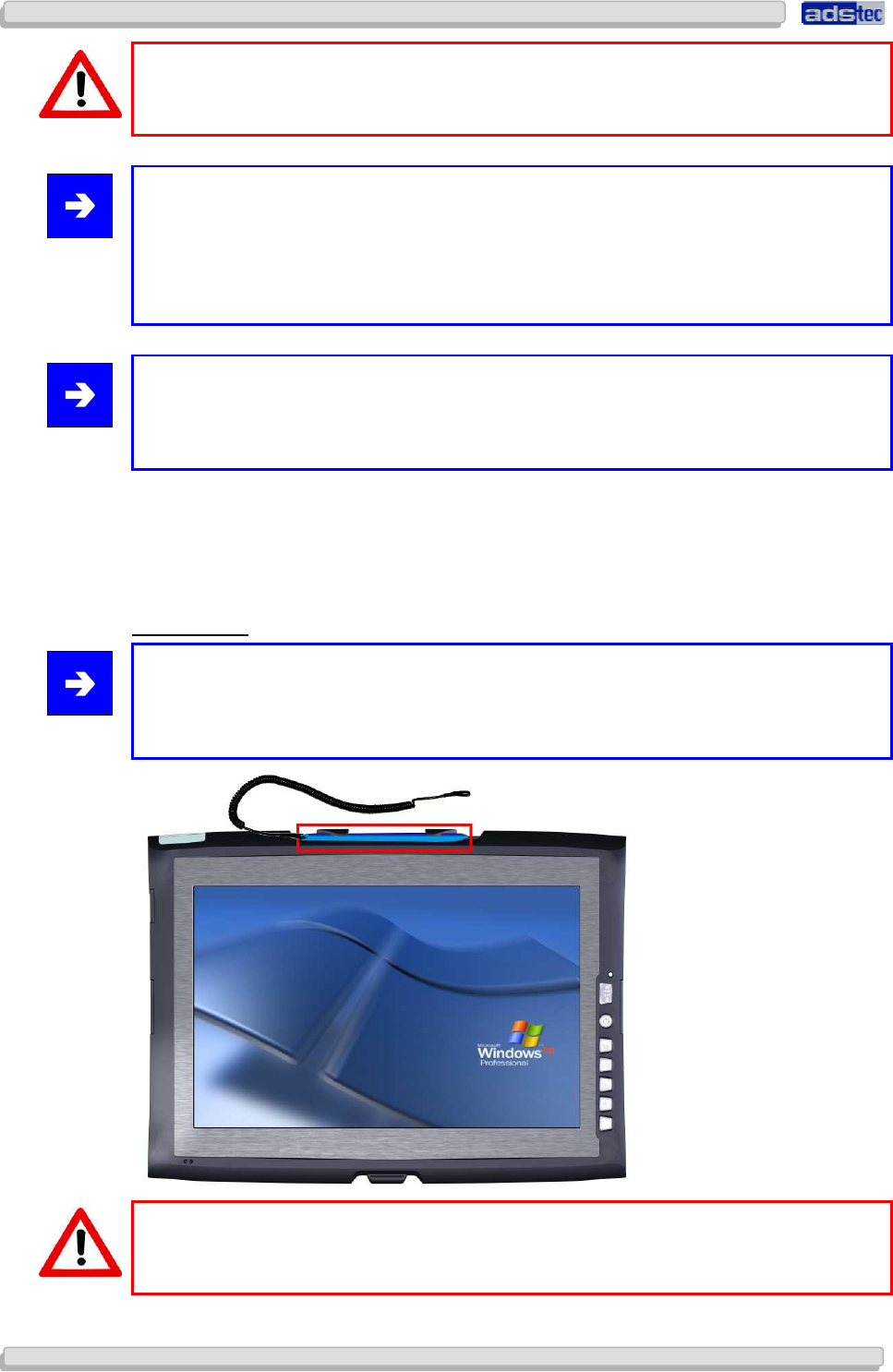
5.3 TOUCH SCREEN
The control system is equipped with an analogue, resistive touch screen. The driver software
required for its use is already integrated in the respective operating system.
TOUCH STYLUS
Note:
This device is equipped with a supplied touch stylus for comfortably operating the touch
screen. This stylus should be used for all works on the device in order to avoid damage to
the display.
Warning:
The protective film on top of the touch screen must not be removed!
User Manual
User ManualUser Manual
User Manual
Compact 4 V 1.2
Compact 4 V 1.2Compact 4 V 1.2
Compact 4 V 1.2
© ads-tec GmbH • Raiffeisenstr.14 • 70771 Leinfelden-Echterdingen 23
2323
23
6
66
6 I
II
INTERFACES
NTERFACESNTERFACES
NTERFACES
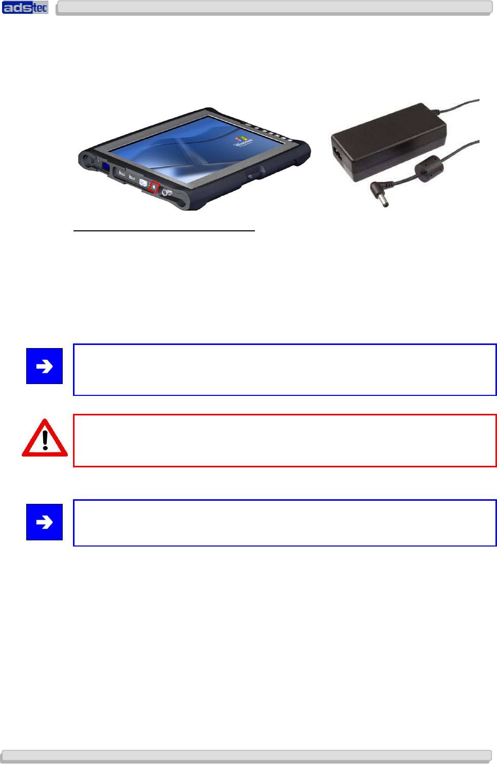
6.1 20V DC POWER SUPPLY
TECHNICAL DATA OF THE POWER ADAPTER
• Power consumption: Max. 70 Watts
• Input voltage: 100…240V AC
• Mains frequency: 50…60Hz
• Current consumption: 3.5A (230V AC)
• Max. switch-on current: < 60A (230V AC)
Note:
The typical power consumption of this device is indicated in the "Technical details"
chapter.
Warning:
This power adapter must never be connected with a Compact
3
device. Likewise, the
Compact
4
device must never be operated with a Compact
3
power supply unit.
Note:
Only approved power cables (e.g. HO5VV-F, at least 3 x 1.00mm2) may be used.
User Manual
User ManualUser Manual
User Manual
Compact 4 V 1.2
Compact 4 V 1.2Compact 4 V 1.2
Compact 4 V 1.2
24
2424
24
© ads-tec GmbH • Raiffeisenstr.14 • 70771 Leinfelden-Echterdingen
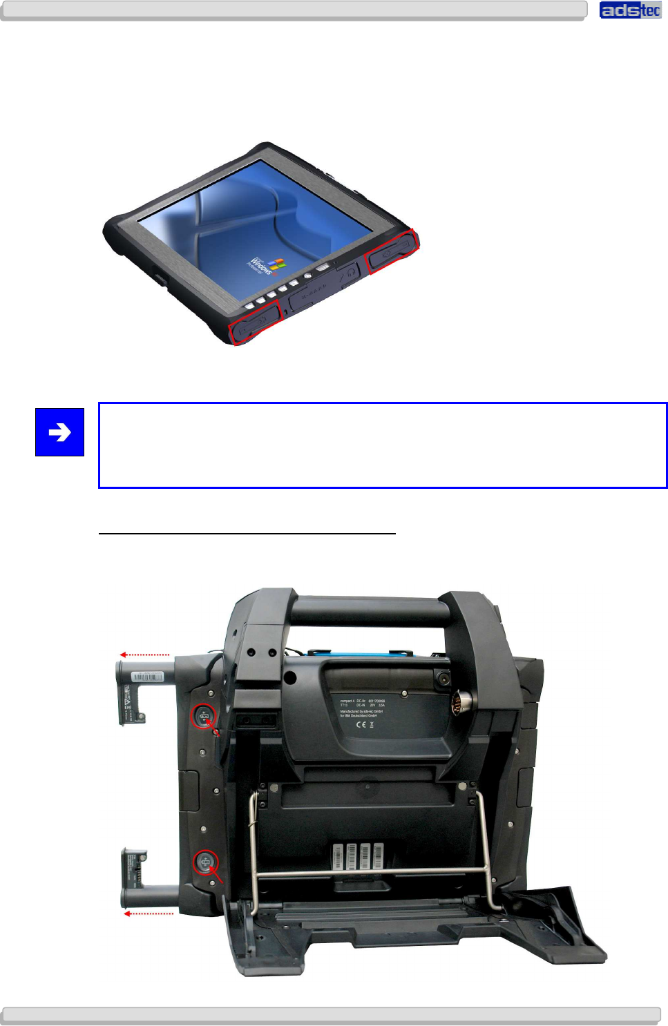
6.2 14.4V DC ACCUMULATOR OPERATING MODE
The device is equipped with two accumulator slots, by means of which the device can be
supplied with power, alternatively. It is provided with a hot swap function which allows you
to replace the accumulator without rebooting.
The accumulators are automatically charged in mains operation (20V).
Note:
If both accumulators are to be replaced while operating the unit, power supply must be
ensured by attaching the supplied power adapter. If you want to replace just one
accumulator, you can do this without attaching an external power supply.
ACCUMULATOR STATUS RETRIEVAL / REPLACEMENT
The Compact4 accumulators can be removed by using a mechanical ejector on the back of
the device.
User Manual
User ManualUser Manual
User Manual
Compact 4 V 1.2
Compact 4 V 1.2Compact 4 V 1.2
Compact 4 V 1.2
© ads-tec GmbH • Raiffeisenstr.14 • 70771 Leinfelden-Echterdingen 25
2525
25
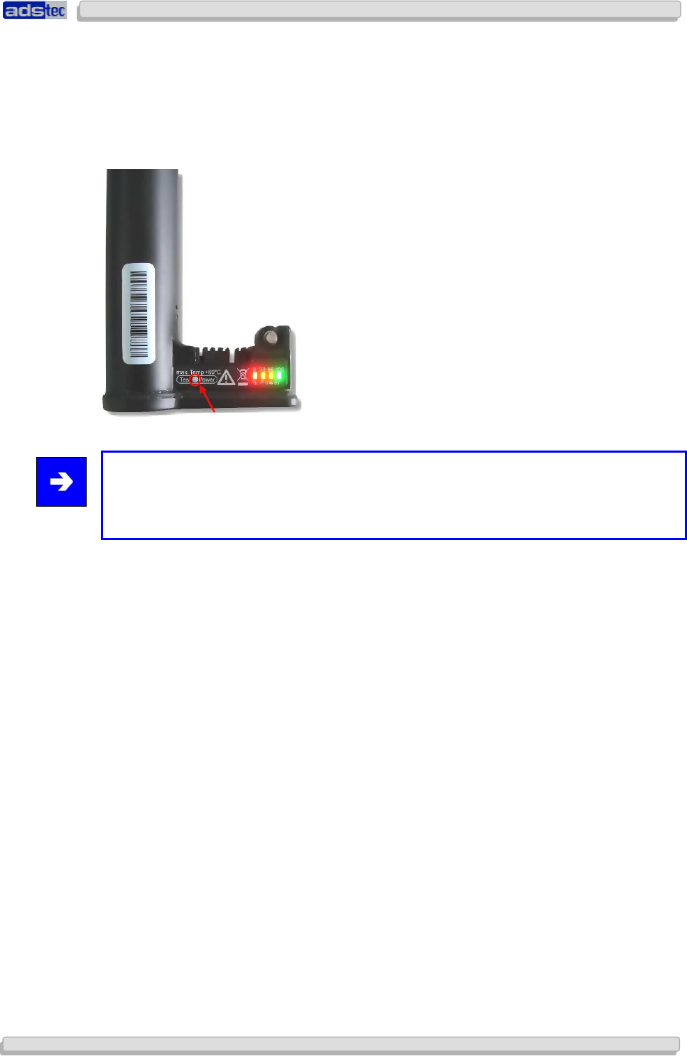
The accumulator status can be retrieved by pushing a button on the accumulator. The
accumulator display will light up for a few seconds and show the current accumulator charge
status on a scale from 0 to 100. If the display lights red, this represents a weak
accumulator. If the display is green, it shows that the accumulator is fully charged. If the
device is in operating mode, the accumulator status can be retrieved by using the supplied
Battery Information & Diagnostics Tool.
Note:
The "Hardware specific software” chapter describes the Battery Information &
Diagnosis Tool, which can be used for retrieving the accumulator status while operating
the unit.
User Manual
User ManualUser Manual
User Manual
Compact 4 V 1.2
Compact 4 V 1.2Compact 4 V 1.2
Compact 4 V 1.2
26
2626
26
© ads-tec GmbH • Raiffeisenstr.14 • 70771 Leinfelden-Echterdingen
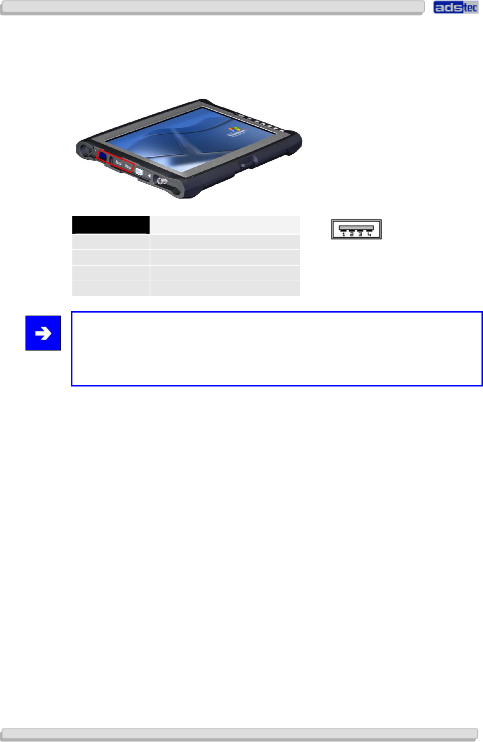
6.3 USB CONNECTIONS
The USB interfaces are used for connecting peripherals with USB connection. The interfaces
comply with the USB 2.0 standard.
PIN NUMBER SIGNAL NAME
1 VDC
2 D -
3 D+
4 GND
Note:
Two of the available USB connections (see red highlighting) offer the opportunity of
outputting a current of 1.5A on one of them at a time. This allows trouble-free operation
of external devices, like an external DVD drive. Both remaining ports output a current of
0.5A by default in this case.
User Manual
User ManualUser Manual
User Manual
Compact 4 V 1.2
Compact 4 V 1.2Compact 4 V 1.2
Compact 4 V 1.2
© ads-tec GmbH • Raiffeisenstr.14 • 70771 Leinfelden-Echterdingen 27
2727
27
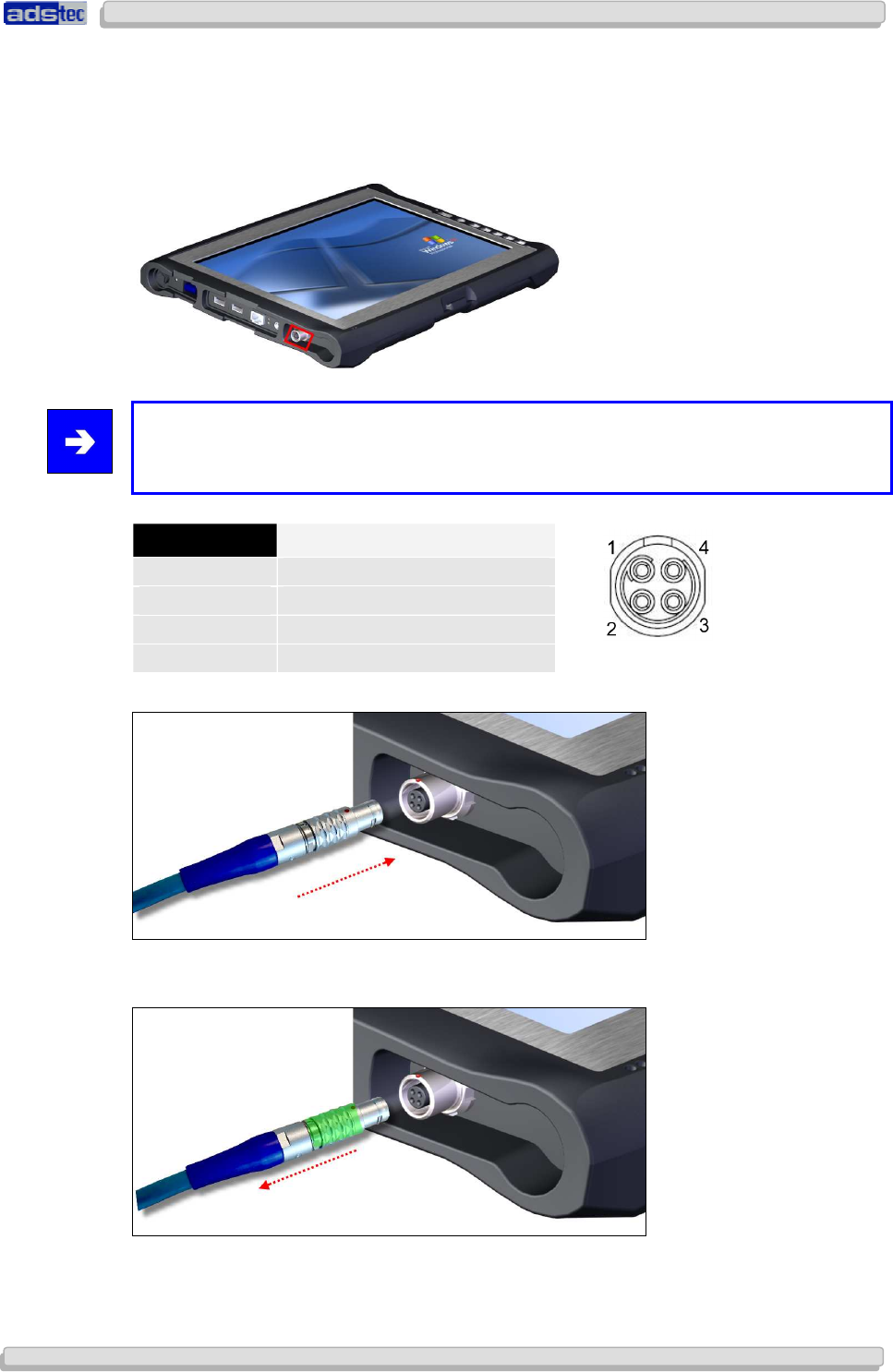
6.4 SD CONNECTOR
By using the SD Connector, the device can be connected to an Ethernet network (10/100
MBit). Data throughputs of 10MB can be achieved with a maximum cable length of 5m.
Note:
This interface does not allow booting via the network. If you want to boot the device via
the network connection, we recommend using the LAN interface.
PIN NUMBER SIGNAL NAME
1 RxD+
2 RxD-
3 TxD+
4 TxD-
The SD Connect cable must be connected so that the red markers match.
For disconnecting the SD Connect cable, it must be pulled rearwards in the area marked in
green. This loosens the snap-in mechanism at the end of the plug.
User Manual
User ManualUser Manual
User Manual
Compact 4 V 1.2
Compact 4 V 1.2Compact 4 V 1.2
Compact 4 V 1.2
28
2828
28
© ads-tec GmbH • Raiffeisenstr.14 • 70771 Leinfelden-Echterdingen
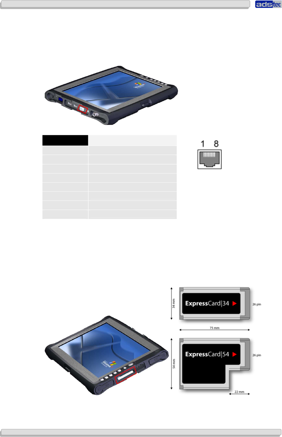
6.5 NETWORK CONNECTION (RJ45)
If the drivers required for functioning are installed on the device, the control system may be
integrated in an Ethernet network supporting the 10/100 MBit standard by using the
Ethernet 10/100BaseT network connector. Specifications of this network topology must be
observed in this case.
PIN NUMBER SIGNAL NAME
1 TX +
2 TX -
3 RX +
4 NC
5 NC
6 RX -
7 NC
8 NC
6.6 EXPRESSCARD SLOT
The device is equipped with an ExpressCard slot, which supports the following ExpressCard
types.
User Manual
User ManualUser Manual
User Manual
Compact 4 V 1.2
Compact 4 V 1.2Compact 4 V 1.2
Compact 4 V 1.2
© ads-tec GmbH • Raiffeisenstr.14 • 70771 Leinfelden-Echterdingen 29
2929
29
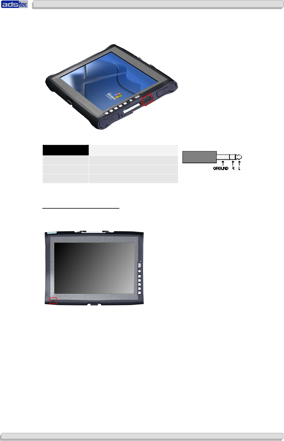
6.7 MIC IN
An external microphone can be connected via the MIC IN socket on the device by means of
a 3.5mm cinch cable.
MICROPHONE IN FRONT PANEL
Additionally, the device has an internal microphone in the front panel. This microphone can
be configured by using the volume control integrated in the operating system.
PIN NUMBER SIGNAL NAME
Ground GND
R Signal, right-hand side
L Signal, left-hand side
User Manual
User ManualUser Manual
User Manual
Compact 4 V 1.2
Compact 4 V 1.2Compact 4 V 1.2
Compact 4 V 1.2
30
3030
30
© ads-tec GmbH • Raiffeisenstr.14 • 70771 Leinfelden-Echterdingen
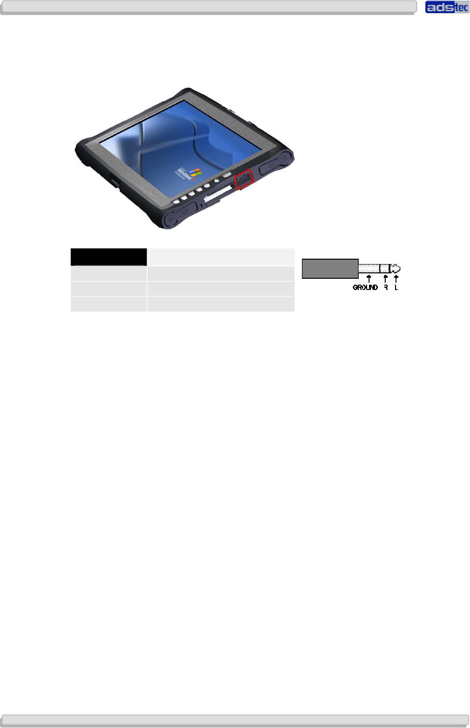
6.8 LINE OUT
By using the Line Out socket of this device and connecting via a 3.5mm cinch cable, a stereo
audio signal can be output to earphones or to external speakers.
PIN NUMBER SIGNAL NAME
Ground GND
R Signal, right-hand side
L Signal, left-hand side
6.9 WLAN
This device is equipped with a radio network card. If the operating system supports this card
by corresponding drivers, the device can be integrated in an Ethernet network with support
for 11 MBit or 54 MBit (802.11b/g compatible). Specifications of this network topology must
be observed in this case.
The device is equipped with a MiniPCI WLAN card including an Atheros chip.
If a device is delivered including operating system by ads-tec, all required device drivers will
also be integrated in the system. Under the "Windows XP Professional" and "Windows XP
Embedded" operating systems, the original "Atheros Client Utility (ACU)" will also be
installed, which can be used for defining new WLAN networks and WLAN connection
settings. The mentioned utility offers a large variety of settings, which in most cases will be
sufficient for meeting individual network requirements. However, the possibility for making
the following settings is lacking:
• Setting the region (e.g. Germany, France, USA, etc.)
• An ad-hoc channel setting, to be specified by region
User Manual
User ManualUser Manual
User Manual
Compact 4 V 1.2
Compact 4 V 1.2Compact 4 V 1.2
Compact 4 V 1.2
© ads-tec GmbH • Raiffeisenstr.14 • 70771 Leinfelden-Echterdingen 31
3131
31
7
77
7
H
HH
HARDWARE
ARDWAREARDWARE
ARDWARE-
--
-SPECIFIC SOFTWARE
SPECIFIC SOFTWARESPECIFIC SOFTWARE
SPECIFIC SOFTWARE
This device is equipped with specific software tools, which allow monitoring of the operating
states.
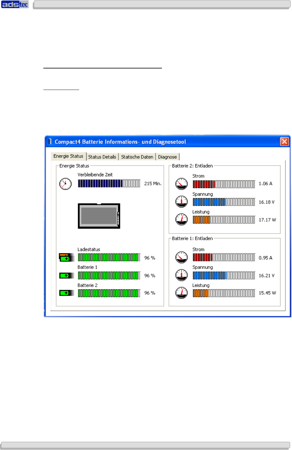
BATTERY INFORMATION & DIAGNOSTICS TOOL
POWER STATUS
The starting page of the battery information tool gives information about the current
accumulator charge status. The lithium-ion accumulators are charged in parallel with the
20V power adapter connected. The charging progress is displayed on the right hand side for
both accumulator slots. The status display on the left shows the remaining accumulator
charging time.
User Manual
User ManualUser Manual
User Manual
Compact 4 V 1.2
Compact 4 V 1.2Compact 4 V 1.2
Compact 4 V 1.2
32
3232
32
© ads-tec GmbH • Raiffeisenstr.14 • 70771 Leinfelden-Echterdingen
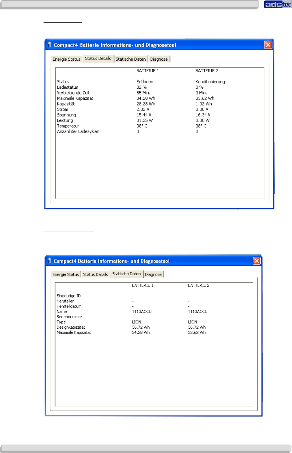
STATUS DETAILS
The Status Detail page lists all starting page data in a table.
STATIC INFORMATION
The "Static Information" tab displays all detail information, e.g. the manufacturer, and the
capacity of the lithium-ion accumulator.
User Manual
User ManualUser Manual
User Manual
Compact 4 V 1.2
Compact 4 V 1.2Compact 4 V 1.2
Compact 4 V 1.2
© ads-tec GmbH • Raiffeisenstr.14 • 70771 Leinfelden-Echterdingen 33
3333
33
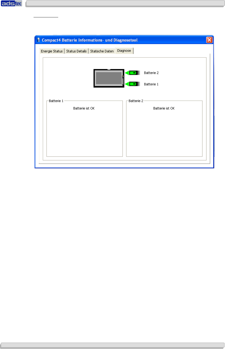
DIAGNOSTICS
The Diagnostics tab gives information about the proper function and about the number of
used lithium-ion accumulators.
User Manual
User ManualUser Manual
User Manual
Compact 4 V 1.2
Compact 4 V 1.2Compact 4 V 1.2
Compact 4 V 1.2
34
3434
34
© ads-tec GmbH • Raiffeisenstr.14 • 70771 Leinfelden-Echterdingen
BRIGHTNESS & VOLUME CONTROL
Brightness and volume can be adjusted by using the function keys in the front panel. The
function of the front keys is provided by a utility called "Genkey service". The actual
adjustment of brightness and volume is managed by the "bvcontrol.exe" utility. This utility
must be active in order to allow setting the brightness and volume by using the keys in the
front panel.
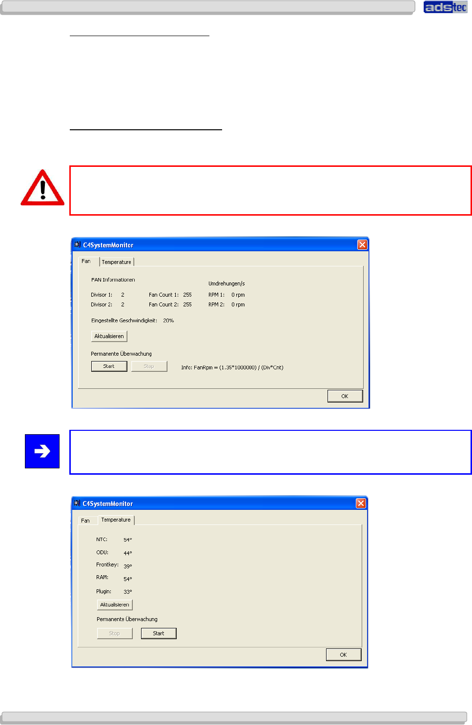
FAN CONTROL & INFORMATION TOOL
The Fan control & information tool monitors the function of the fan, as well as the current
temperature.
Warning:
Malfunction of a fan will be displayed through a popup window.
Note:
The fan RPM will only be shown if the fan function is active.
User Manual
User ManualUser Manual
User Manual
Compact 4 V 1.2
Compact 4 V 1.2Compact 4 V 1.2
Compact 4 V 1.2
© ads-tec GmbH • Raiffeisenstr.14 • 70771 Leinfelden-Echterdingen 35
3535
35
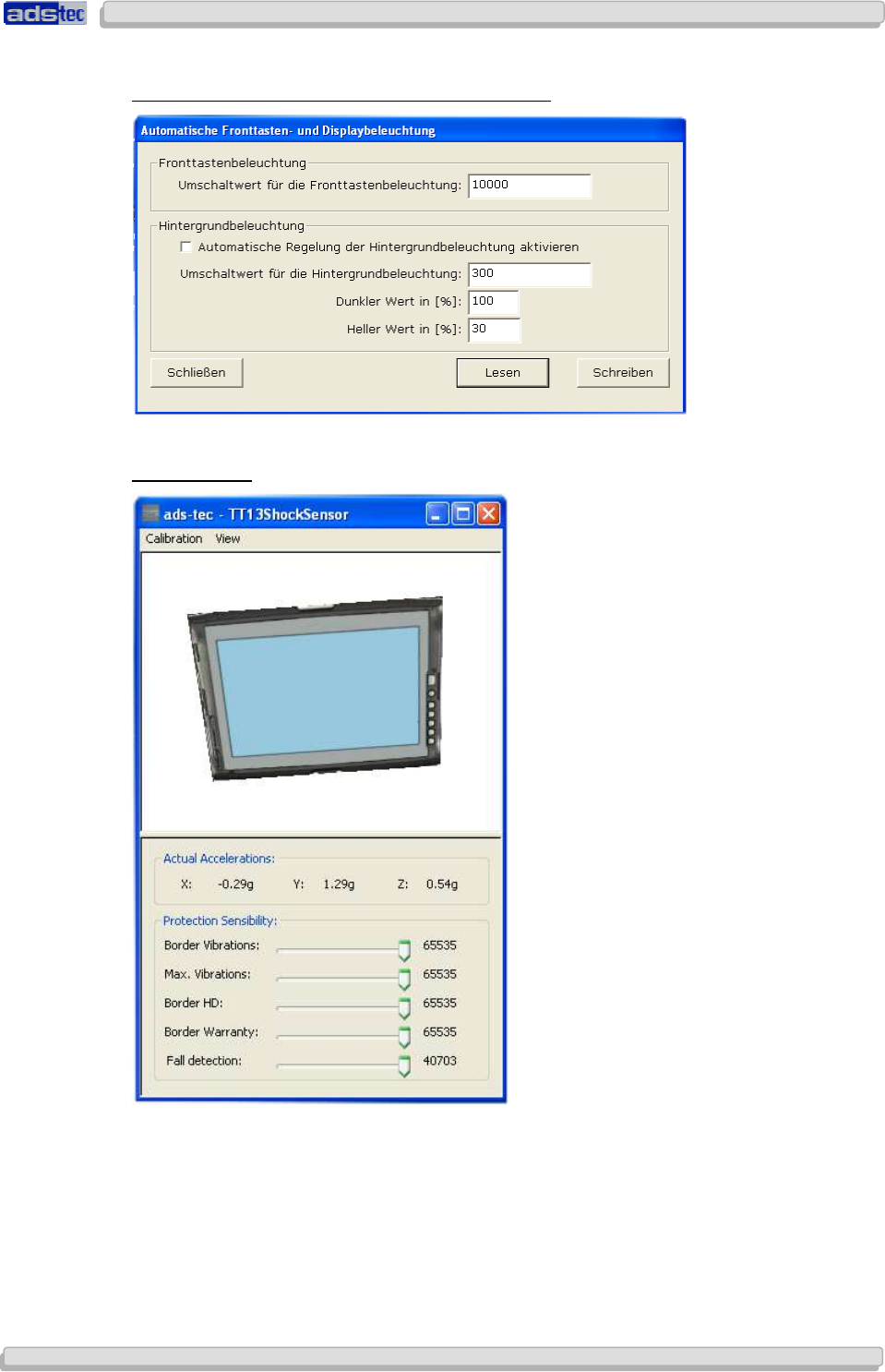
AUTOMATIC FRONT KEYS AND DISPLAY ILLUMINATION
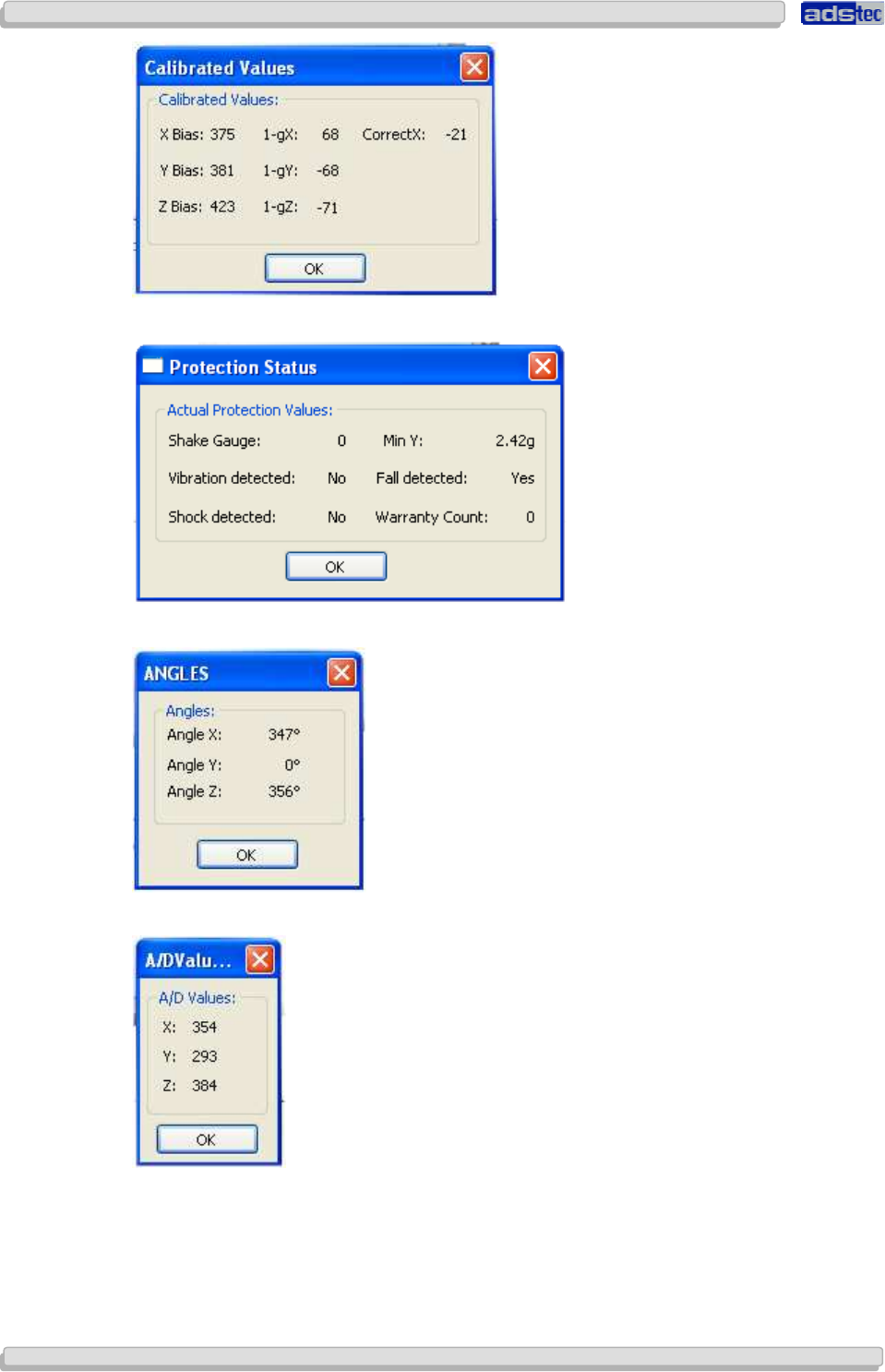
SHOCK SENSOR
User Manual
User ManualUser Manual
User Manual
Compact 4 V 1.2
Compact 4 V 1.2Compact 4 V 1.2
Compact 4 V 1.2
36
3636
36
© ads-tec GmbH • Raiffeisenstr.14 • 70771 Leinfelden-Echterdingen
User Manual
User ManualUser Manual
User Manual
Compact 4 V 1.2
Compact 4 V 1.2Compact 4 V 1.2
Compact 4 V 1.2
© ads-tec GmbH • Raiffeisenstr.14 • 70771 Leinfelden-Echterdingen 37
3737
37
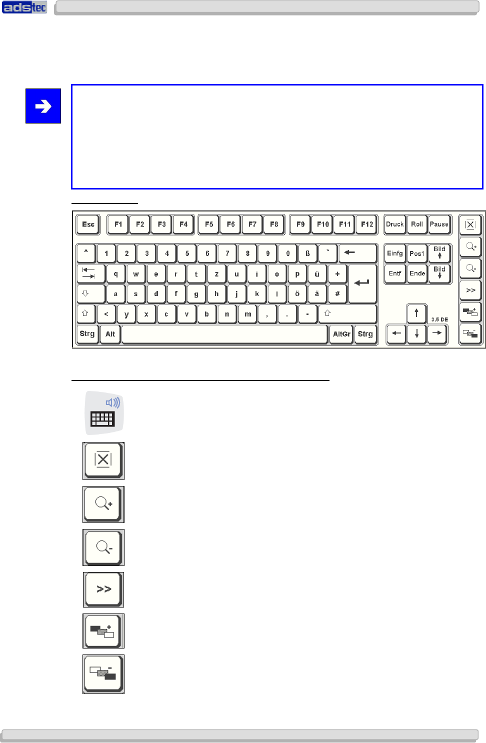
7.1 SOFT KEYBOARD
By using the soft keyboard, data can be entered via the touch screen like with an external
keyboard.
Note:
The soft keyboard of the Compact
4
device can be delivered in 21 languages. Depending
on the selected language, the soft keyboard representation and function may vary. Basic
functions are identical with all languages. The following languages are available:
German / English (US) / English (UK) / French / Italian / Spanish / Portuguese / Finnish /
Turkish / Danish/ Swedish / Japanese / Korean / Greek / Czech / Polish / Romanian /
Russian / Serbian / Croatian / Hungarian
DEFAULT VIEW:
HOW TO OPERATE THE SOFT KEYBOARD FROM VERSION 3.11:
Activate and deactivate the soft keyboard for letter/character input
using the touch screen
Deactivate the soft keyboard
Soft keyboard representation, zoom in
Soft keyboard representation, zoom out
Switch to numeric key pad representation
Increase the soft keyboard transparency
Decrease the soft keyboard transparency
User Manual
User ManualUser Manual
User Manual
Compact 4 V 1.2
Compact 4 V 1.2Compact 4 V 1.2
Compact 4 V 1.2
38
3838
38
© ads-tec GmbH • Raiffeisenstr.14 • 70771 Leinfelden-Echterdingen
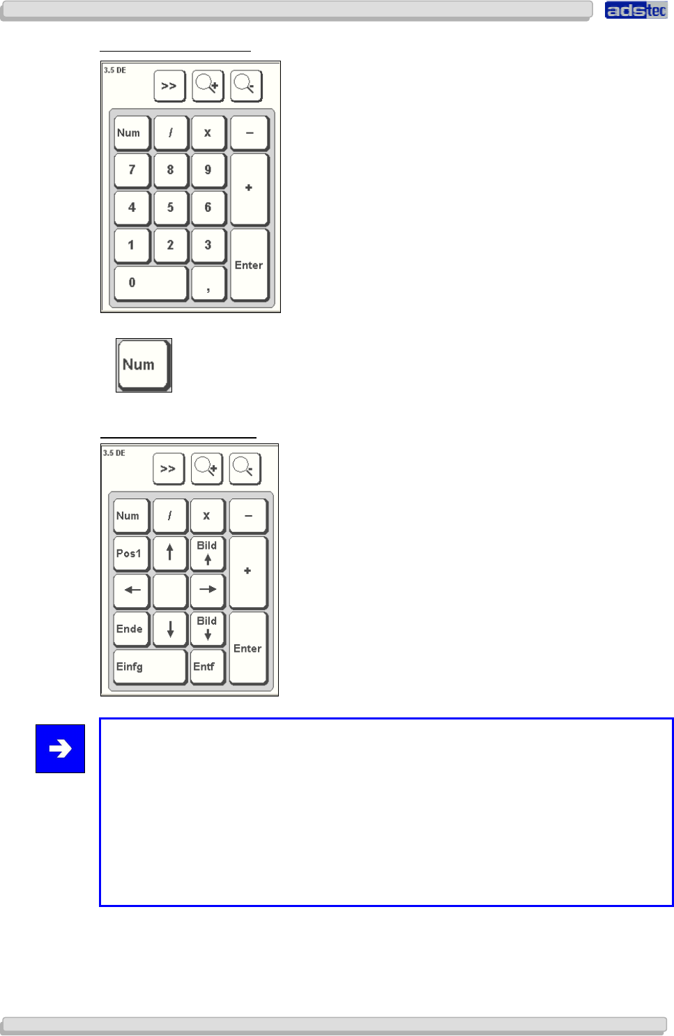
NUMERIC KEY-PAD VIEW:
Switch to representation of the function-key bar
FUNCTION-KEY BAR VIEW:
Note:
If a function is to be activated, which requires pressing two keys at the same time (e.g.
Alt + F4); these keys have to be pushed one after another at the soft keyboard, and the
special keys Shift, Alt and Strg must always be pushed first.
Due to differences in programming of a large variety of software, we cannot ensure that
the soft keyboard works properly with all software.
When deactivating the soft keyboard, the previously active state (alphanumeric / numeric
keys or function keys) will be stored and will be displayed when re-activating the
keyboard.
User Manual
User ManualUser Manual
User Manual
Compact 4 V 1.2
Compact 4 V 1.2Compact 4 V 1.2
Compact 4 V 1.2
© ads-tec GmbH • Raiffeisenstr.14 • 70771 Leinfelden-Echterdingen 39
3939
39
8
88
8 A
AA
ACCESSORIES
CCESSORIESCCESSORIES
CCESSORIES
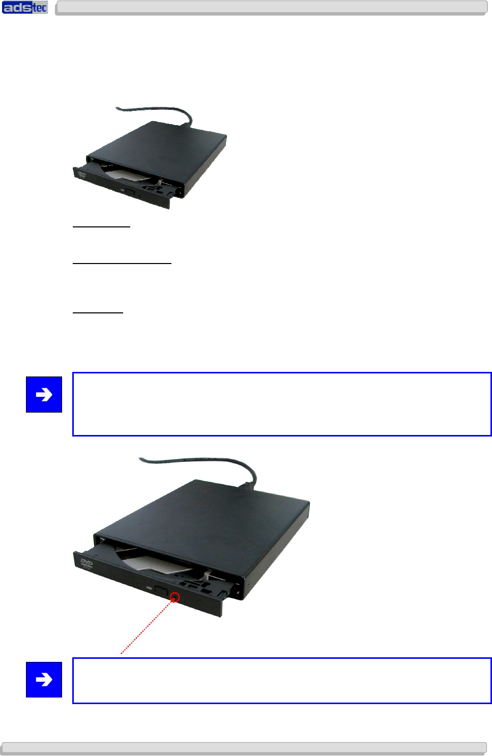
8.1 DVD DRIVE / EXTERNAL TYPE
CONNECTION
The DVD drive can be connected to the Compact4 device by using the USB interface.
DRIVER INSTALLATION
The required drivers will be installed automatically as soon as the DVD drive is connected
with the USB interface.
FUNCTIONS
The Compact4 device must be switched on to open the drive. After pushing the Eject button,
the drawer jumps open and must be pulled out completely. The CD/DVD is now placed with
the opening on top of the centre piece and carefully pushed downwards until the disk holder
snaps in. Subsequently the drive must be pushed in.
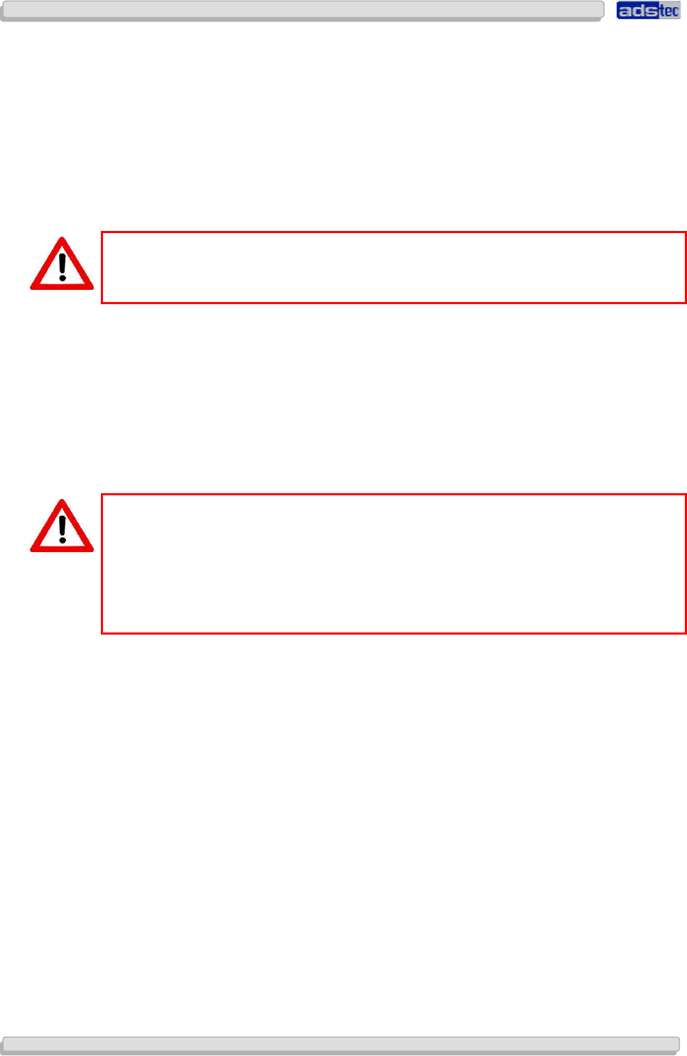
Note:
The drive can also be opened by using a mechanical ejector without any power supply. In
order to do this, you'd have to push with a pointed object into the marked opening until
the drawer jumps open.
Note:
The DVD drive is of the slim-line drive type.
User Manual
User ManualUser Manual
User Manual
Compact 4 V 1.2
Compact 4 V 1.2Compact 4 V 1.2
Compact 4 V 1.2
40
4040
40
© ads-tec GmbH • Raiffeisenstr.14 • 70771 Leinfelden-Echterdingen
8.2 SAFETY OF LASER PRODUCTS
This product has been designed and manufactured according to FDA regulations “title
21.CFR. chapter1, subchapter J.based on the radiation Control for Health and Safety Act of
1968”. And is classified as a class 1 laser product. There is no hazardous invisible laser
radiation during operation because invisible laser radiation emitted inside of this product is
completely confined in the protective housings.
The label required in this regulation is shown bellow.
Caution:
Use of controls or adjustments or performance of procedures other than those specified
herein may result in hazardous radiation exposure.
Optical pickup
Type : TOP1100S
Manufacturer : TopRay Technologies, Inc
Laser output : Less than 0.5mW on the objective lens
Wavelength : 770-800nm (CD)
645-662nm (DVD)
Standard : IEC60825-1 : 2001
Caution:
Class 1M Visible and Invisible Laser Radiation when open. Do not view directly with optical
instruments.
Achtung:
Sichtbare und Unsichtbare Laserstrahlung Klasse 1M, wenn Abdeckung geöffnet. Nicht
direkt mit Optischen Instrumenten betrachten.
User Manual
User ManualUser Manual
User Manual
Compact 4 V 1.2
Compact 4 V 1.2Compact 4 V 1.2
Compact 4 V 1.2
© ads-tec GmbH • Raiffeisenstr.14 • 70771 Leinfelden-Echterdingen 41
4141
41
9
99
9 R
RR
REG
EGEG
EGULATORY
ULATORY ULATORY
ULATORY A
AA
APPROVALS
PPROVALSPPROVALS
PPROVALS
9.1 CERTIFICATIONS / TESTINGS
The Compact 4 system has the following certifications:
EN61000-6-2 device complies with standard CE compatibility (class A)
EN61000-6-4 device complies with standard
UL/cUL201
Application for certification is filed
FCC permission
Application for certification is filed
GOST-R certificate
Application for certification will be filed
MIC certification
Application for certification will be filed
EU countries
2.400 MHz – 2.483,5 MHz
5.150 MHz – 5.350 MHz
5.470 MHz – 5.725 MHz
Application for certification in USA / Canada
2.400 MHz - 2483,5 MHz
5.150 MHz - 5.350 MHz
5.725 MHz – 5.875 MHz
Application for certification in Japan
2.400 MHz – 2.483,5 MHz
5.150 MHz – 5.350 MHz
5.470 MHz – 5.725 MHz
Application for WLAN certificates
for 802.11 a/b/g for the
Application for certification in Australia
2.400 MHz – 2.483,5 MHz
5.150 MHz – 5.350 MHz
5.470 MHz – 5.725 MHz
Note:
A respective conformity declaration for the authority in charge is available on request from
the manufacturer.
All connected components, as well as cable connections must also meet these
requirements for compliance with the EMC legislation. For this reason, screened bus and
LAN cables including screened connectors must be used and installed according to the
instructions in this user manual.

User Manual
User ManualUser Manual
User Manual
Compact 4 V 1.2
Compact 4 V 1.2Compact 4 V 1.2
Compact 4 V 1.2
42
4242
42
© ads-tec GmbH • Raiffeisenstr.14 • 70771 Leinfelden-Echterdingen
9.2 ELECTROMAGNETIC COMPATIBILITY (EMC)
Certificate of acceptance in accordance with the Federal Electromagnetic Compatibility Act in
Germany ("EMVG") of 2007 (respectively the EMC Directive no. 2004/108/EC).
In accordance with the Federal Electromagnetic Compatibility Act in Germany, this device is
authorised to carry the EC conformity sign "CE". Liable party for this conformity declaration
is according to para. 5 of the "EMVG" legislation:
ads-tec GmbH
Raiffeisenstrasse 14
D – 70771 Leinfeld – Echterdingen
Information in accordance with "EMVG", para. 3, section (2) 2:
This device complies with the protective requirements according to EN 61000-6-2 and EN
61000-6-4, class A.
Any equipment of class A must be provided with the following warning message: "Warning! -
This is equipment of class A. This unit might cause radio interferences in living areas; in this
case the operator might be required to take suitable protective measures."
User Manual
User ManualUser Manual
User Manual
Compact 4 V 1.2
Compact 4 V 1.2Compact 4 V 1.2
Compact 4 V 1.2
© ads-tec GmbH • Raiffeisenstr.14 • 70771 Leinfelden-Echterdingen 43
4343
43
9.3 FCC-APPROVAL
Note:
This device complies with Part 15 of the FCC Rules [and with RSS-210 of Industry
Canada].
Operation is subject to the following two conditions:
this device may not cause harmful interference, and this device must accept any
interference received, including interference that may cause undesired operation.
Note:
Changes or modifications made to this equipment not expressly approved by ads-tec
GmbH may void the FCC authorization to operate this equipment.
Note:
This equipment has been tested and found to comply with the limits for a Class A digital
device, pursuant to Part 15 of the FCC Rules. These limits are designed to provide
reasonable protection against harmful interference when the equipment is operated in a
commercial environment. This equipment generates, uses, and can radiate radio
frequency energy and, if not installed and used in accordance with the instruction manual,
may cause harmful interference to radio communications. Operation of this equipment in
a residential area is likely to cause harmful interference in which case the user will be
required to correct the interference at his own expense.
Note:
Radiofrequency radiation exposure Information:
This equipment complies with FCC radiation exposure limits set forth for an uncontrolled
environment. This equipment should be installed and operated with minimum distance of
0cm between the radiator and your body. This transmitter must not be co-located or
operating in conjunction with any other antenna or transmitter.
Note:
This Class A digital apparatus complies with Canadian ICES-003.
Cet appareil numérique de la classe A est conforme à la norme NMB-003 du Canada.

User Manual
User ManualUser Manual
User Manual
Compact 4 V 1.2
Compact 4 V 1.2Compact 4 V 1.2
Compact 4 V 1.2
44
4444
44
© ads-tec GmbH • Raiffeisenstr.14 • 70771 Leinfelden-Echterdingen
10
1010
10 T
TT
TECHNICAL DETAILS
ECHNICAL DETAILSECHNICAL DETAILS
ECHNICAL DETAILS
10.1 DISPLAY DATA
Display 13.3" TFT, WXGA 1280 x 800 pixels
Display colours 262,144 colours
Brightness 200 cd/m² at max (adjustable)
Touch screen Resistive 5-wire touch screen
Contrast 400:1
10.2 COMPUTER DATA
Processor Intel Pentium M Yonah ULV 1.06GHz Core Solo 423 (5.5W)
RAM 2GB DDR2 SODIMM PC2-5300
Chip set Intel 855 GME
Graphic memory A maximum of 64 MB, shared memory
Mass storage device 2.5" SATA 120 GB hard disk
Interfaces at the base device: 3 x USB 2.0 (1 of which is recessed for
flash memory stick)
at the multifunction unit: 1x COM (SUB-D), 3x USB 2.0, 1x MIL
Network 1x Ethernet (10/100 MBit) RJ 45,
1x Ethernet (10/100 MBit) via SD connector
Wireless WLAN, 802.11 b/g
Slots 1x Express card, wide slot
Sound 2x speakers, 1x microphone, 1x headphone out, 1x
microphone in
Power supply 20V DC +/- 20%
Accumulator Li-Ion smart-battery accumulator with 14.4V and 32Wh, 2
accumulator slots
10.3 GENERAL DATA
External dimensions 355 mm x 261 mm x 41 mm (W x H x D)
Weight approx. 3.0 kg
Protection class IP 54
Power consumption 24 Watts (typical)
Max. switch-on current 7 Amperes (for 2ms)

User Manual
User ManualUser Manual
User Manual
Compact 4 V 1.2
Compact 4 V 1.2Compact 4 V 1.2
Compact 4 V 1.2
© ads-tec GmbH • Raiffeisenstr.14 • 70771 Leinfelden-Echterdingen 45
4545
45
11
1111
11 S
SS
SERVICE A
ERVICE AERVICE A
ERVICE AND
ND ND
ND S
SS
SUPPORT
UPPORTUPPORT
UPPORT
ads-tec and appointed partner companies offer you comprehensive maintenance and
support services, ensuring quick and competent support should you have any questions or
concerns with regard to ads-tec products and equipment.
ads-tec products may also be provided and installed by partner companies. Such devices
may have customised configurations. Should any questions arise with regard to such specific
settings and software installations, please contact the system supplier in question as ads-tec
will not be able to reply to such questions.
ads-tec does not provide support services for any device or unit that was not bought directly
from ads-tec. In any such case, maintenance and support is provided solely by the partner
company that supplied the device or unit.
11.1 ADS-TEC SUPPORT
The ads-tec support team is available for inquiries by direct customers between 8:30am and
5:00pm, Monday to Friday. The support team can be reached via phone, fax or email.
Tel: +49 (0) 711 / 45894-500
Fax: +49 (0) 711 / 45894-990
Email: info@ads-tec.com
11.2 COMPANY ADDRESS
ads-tec
Automation Daten- und Systemtechnik GmbH
Raiffeisenstraße 14
70771 Leinfelden-Echterdingen
Germany
Tel: +49 (0) 711 / 45894-0
Fax: +49 (0) 711 / 45894-990
Email: info@ads-tec.de
Web: www.ads-tec.de