dormakaba Canada LPR10M Proximity Reader User Manual LEGIC Installation Manual Part 2
Kaba Ilco Inc. Proximity Reader LEGIC Installation Manual Part 2
Contents
- 1. LEGIC Installation Manual Part 2
- 2. LEGIC Installation Manual Part 1
- 3. LEGIC Installation manual Front Cover
LEGIC Installation Manual Part 2
PK2963 03/03 Issue 1 3 of 4
NOTES:
1. If the reader is fixed onto a metal surface, use the spacer provided
in the kit to ensure that there is minimal interference to the reader
caused by its proximity to the metal. The spacer is optional for
concrete or drywall.
1. If distance between reader and the DCD is greater than the length
of cable supplied, an extension cable may be required. The
maximum distance is 200 meters of AWG-22 cable. (Alpha 1299
series recommended)
1. The LPR-10M interfaces with the access controller through the 9-
wire cable. Along with power and ground, the signals carried by the
cable are grouped into two categories: the data interface and the
user interface control. Each category can be programmed to
emulate various interface standards, adding flexibility for interfacing
with more access controller types.
Interconnecting Cable
The interconnecting cable is a 9-wire shielded cable that carries the
signals and power between the LPR-10M and the access control unit.
All signals listed in the Table below are TTL-level compatible.
Color
Signal name
Wiegand Interface
Signal
Direction
Signal name
Clock & Data Interface
Signal
Direction
Red
+DC
-
+DC
-
Black
GND
-
GND
-
Violet
-
-
/CARD_IN
Output
Green
DATA0
Output
/DATA
Output
White
DATA1
Output
CLOCK
Output
Drain wire
SHIELD
-
SHIELD
-
Orange
/GREEN
Input
/GREEN
Input
Brown
/RED
Input
/RED
Input
Yellow
/BUZZER
Input
/BUZZER
Input
Blue
/HOLD
Input
/HOLD
Input
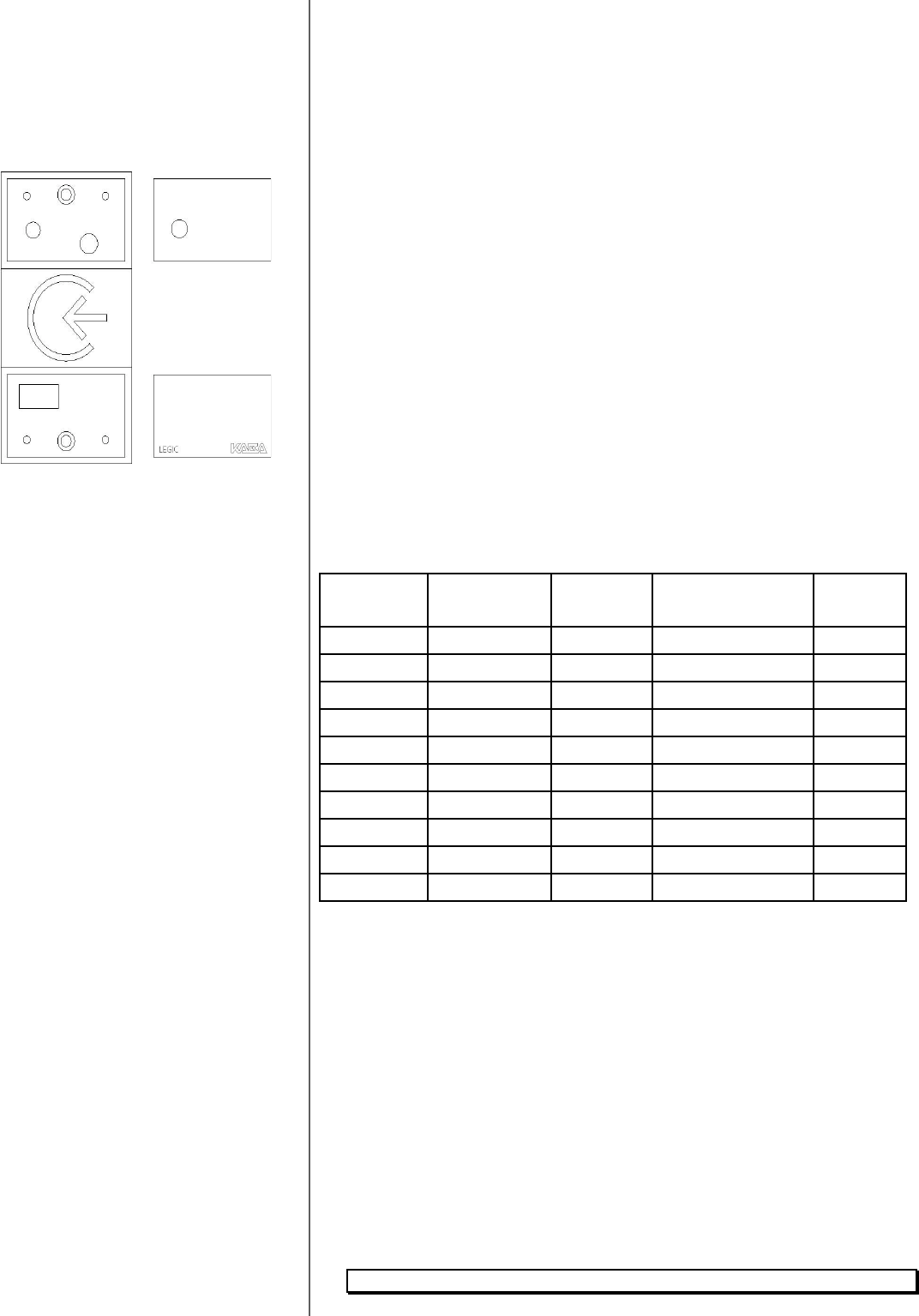
Figure 2: Fascia
PK2963 03/03 Issue 1 4 of 4
Installation - Connecting to Millenium Door Control Device
(DCD)
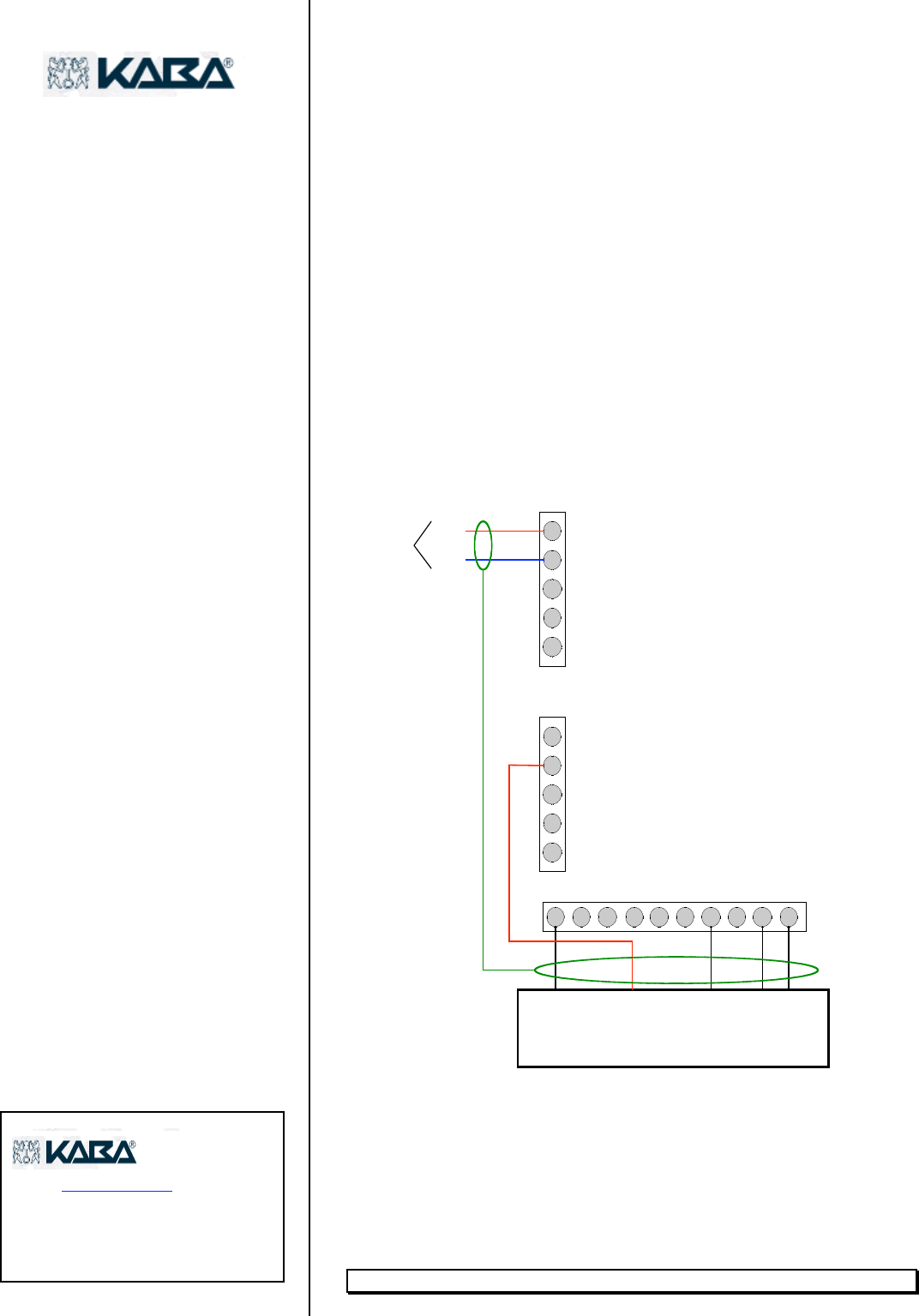
1. Connect reader unit to the DCD at the J2 and J5 terminals. Refer
to wire colors in the table above, and refer to Figure 2 on the back
of this sheet.
2. Verify the Reader Select Jumper cap is installed on the DCD’s J1
terminal.
3. Tape ends of the four unterminated conductor wires: /CARD IN,
Shield, /buzzer and /hold.
4. Apply power to DCD. The red indicator on the reader should
illuminate.
5. To test the reader, the door MUST HAVE BEEN CREATED in the
Millenium software. (Refer to Millenium Operations Manual)
987654321 10
J2
Data 0
Ground
LED
J5
5
4
3
2
1
5
4
3
2
1
J3
TXR +
TXR -
Trunk Data
Communications
Black
Green
Red
White
Brown
Jumper J1 is Inserted
Maximum Cabling Distance is 500 ft from DCD to Reader.
Data 1
Figure 3: Power Connection
www.kabailco.com
1-800-849-8324
CAUTION
Changes or modifications not expressly approved by Kaba Ilco
could void the user’s authority to operate the equipment.