dormakaba EAD KRR9125-K5 Desktop Reader User Manual TM RemoteReader9125 AM US CAN 201603 en
Kaba GmbH Desktop Reader TM RemoteReader9125 AM US CAN 201603 en
UserManual.wiki
>
dormakaba EAD
>
KRR9125 K5 User Manual
user manual
Navigation menu
Upload a User Manual
Namespaces
Wiki Guide
HTML
PDF
Info
Views
User Manual
Discussion / Help
Navigation

![About this Document Technical Manual8 04045708 - 04/2016 Kaba Remote Reader 91 25-AM (US/CAN)1.4 Supplementary DocumentsSupplementary documentation is available on the Kaba website. The technical man-uals are located in a secured area of the website.• Access is only possible after logging in.• An account will need to be created before logging in for the first time.Access and login:1. In the browser, access the Kaba page http://www.kaba.com.2. Select the language in the top right.3. Under "Products", select the "Access Management" or "Workforce Management"product division.4. In the top right section of the screen, click on the following symbol:.5. Enter your e-mail address and password and login or create an account (see be-low).ðThe technical manuals can be found under "Downloads".Create account:1. Click "Create account".2. Complete the data fields and confirm.ðA confirmation link will be sent to your e-mail address.3. To activate your account, click on the confirmation link in your e-mail.1.5 Change LogThe most important changes to the last issue of this manual are listed below:Version number Edition Brief descriptionTM_RemoteReader9125-AM-US-CAN_20160303/2016 First edition (US /CAN)1.6 Orientation in the DocumentThis document contains the following orientation aids to facilitate finding of specifictopics:• An index in the alphabetical order is given at the end of the manual.• The table of contents at the beginning of the manual gives an overview of alltopics.• The header always contains the respective main chapter.• This step-by-step guide goes through the installation and commissioning.• Cross references always indicate the number of the chapter in which the supple-mentary information can be found. Example [ 5.7].](https://usermanual.wiki/dormakaba-EAD/KRR9125-K5/User-Guide-3156567-Page-8.png)
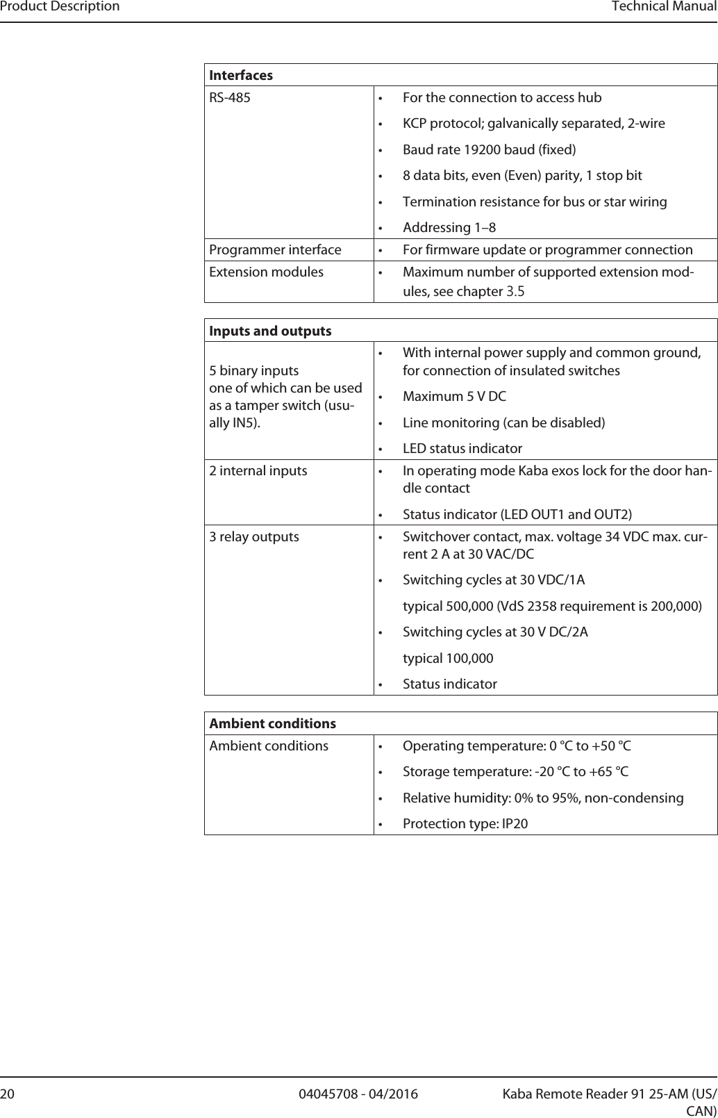
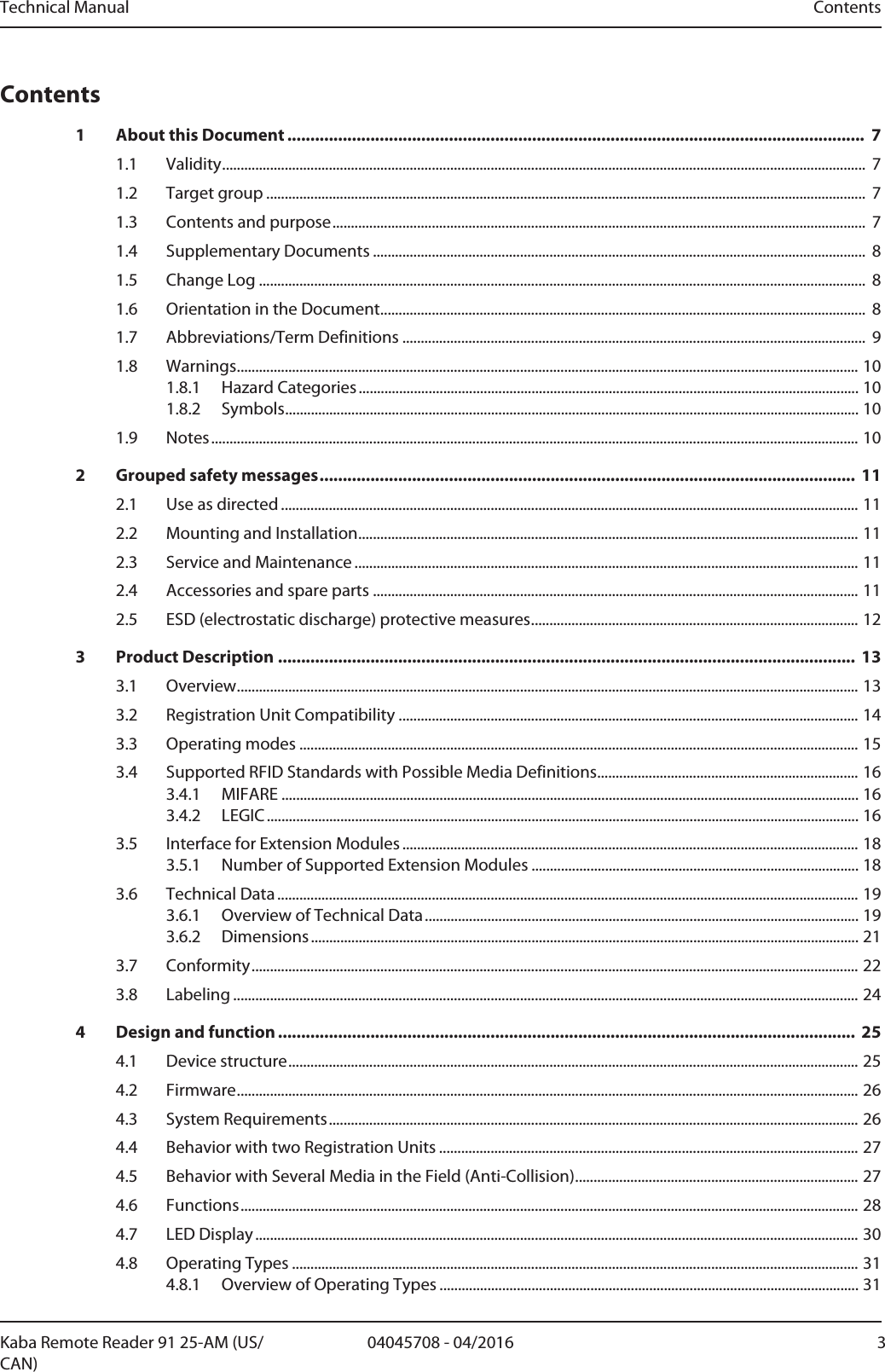
![Product Description Technical Manual22 04045708 - 04/2016 Kaba Remote Reader 91 25-AM (US/CAN)3.7 ConformityThis product conforms to the following standards:EN 60950-1 : 2014-08 EN 60950-1:2006/A2:2013UL 60950-1:2007/R:2014-10CAN/CSA-C22.2 No. 60950-1:2007/A2:2014-10EN 301 489-1 V1.9.2 : 2011-09EN 301 489-3 V1.6.1 : 2013-08EN 300 330-1 V1.8.1 : 2014-12EN 300 330-2 V1.6.1 : 2014-12in accordance with the provisions of the EC directives2014/53/EC: R&TTE DirectiveRoHS This device complies with the regulations of the Directive 2011/65/EU of the Euro-pean Parliament and of the Council of June 8, 2011, on the restriction of the use ofcertain hazardous substances in electrical and electronic equipment.The original Declaration of Conformity can be downloaded from www.kaba.com/conformity in PDF format.Tested Standard:FCC Code of Federal Regulations, CFR 47, Part 15, Sections 15.205, 15.207, 15.215 and15.225FCC ID NVI-KRR9125-K5FCC § 15.19This device complies with Part 15 of the FCC rules. Operation is subject to the follow-ing two conditions: (1) This device may not cause harmful interference, and (2) thisdevice must accept any interference received, including interference that may causeundesired operation.FCC § 15.21 (Warning Statement)[Any] changes or modifications not expressly approved by the party responsible forcompliance could void the user’s authority to operate the equipment.FCC § 15.105Note: This equipment has been tested and found to comply with the limits for a ClassA digital device, pursuant to part 15 of the FCC Rules. These limits are designed toprovide reasonable protection against harmful interference when the equipment isoperated in a commercial environment. This equipment generates, uses, and can ra-diate radio frequency energy and, if not installed and used in accordance with the in-struction manual, may cause harmful interference to radio communications. Opera-tion of this equipment in a residential area is likely to cause harmful interference inwhich case the user will be required to correct the interference at his own expense.Tested Standard:Industry Canada Radio Standards Specifications RSS-GEN Issue 4, Sections 8.8, 8.9and 8.10 and RSS-210 Issue 8, Section A2.6 (Category I Equipment)IC:11038A-KRR9125-K5ICES-003This Class A digital apparatus complies with Canadian ICES-003. Cet appareilnumérique de la classe A est conforme à la norme NMB-003 du Canada.](https://usermanual.wiki/dormakaba-EAD/KRR9125-K5/User-Guide-3156567-Page-22.png)
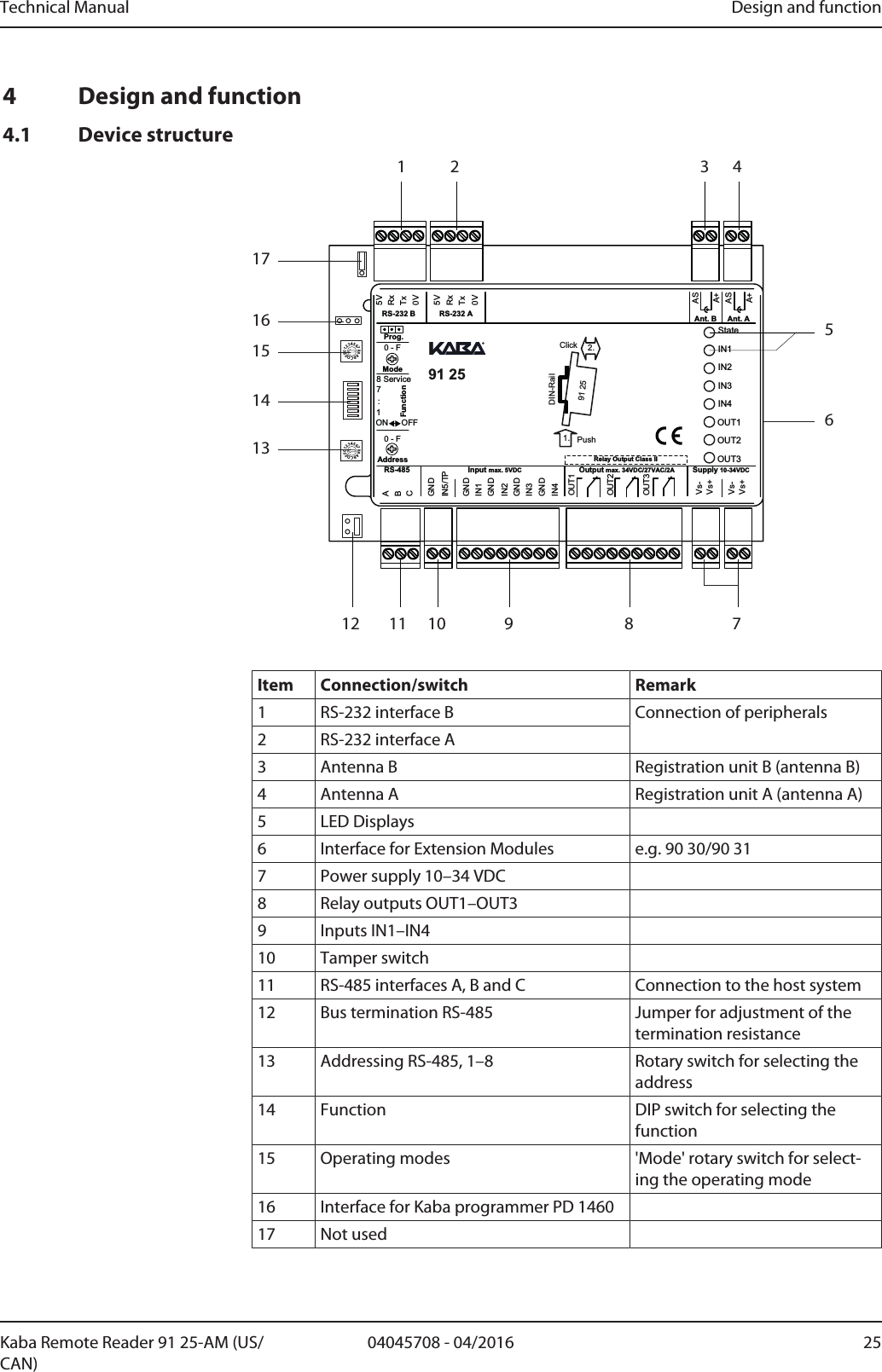
![Design and function Technical Manual26 04045708 - 04/2016 Kaba Remote Reader 91 25-AM (US/CAN)The functions and connections of the interfaces, inputs, relay outputs, rotary and DIPswitches are described in the chapterDesign and function [}4].4.2 FirmwareThe hardware of this product is used in various Kaba system solutions. The functionsand possible uses of the product are determined by the firmware used.This manual solely describes the Kaba remote reader 91 25 functional type accessmanager (AM).Firmware designationReader type MMIFAREALEGICBLEGIC or MIFARE(determined during commissioning)MRD (multi RFID device)Device type RC CompactreaderRR Remotereader 91 15RE Remotereader 91 25Functional type AE300 V4 or N300/T300/U300 V3BAccess ManagerCSubterminalEAMC/II (cDML)Version number xx.xx VersionAddition 1 RFinal, approved versionAddition 2 ASubversionAddition 3 _ReserveExampleDesignation of firmware for Kaba remote reader 91 25 with functional type accessmanager:• BREB03.xxRxx (MRD)Firmware mark on the productDevices with firmware with the functional type access manager bear a mark reading"Type: Access manager" on the identification plate.4.3 System Requirements• Kabaexos9300 release 4.0.1 and higher• Kaba access manager 92 00 AM firmware version 3.00 and higherFurther details can be found in the Release Overviews and Release Notes.](https://usermanual.wiki/dormakaba-EAD/KRR9125-K5/User-Guide-3156567-Page-26.png)
![Design and function Technical Manual28 04045708 - 04/2016 Kaba Remote Reader 91 25-AM (US/CAN)4.6 FunctionsAll data for access decisions are saved in the host control device. The authorizationcheck of a badge and access control are undertaken by the control device.Functions available before the remote reader is connected to the host systemStandalone access control (without host system); see chapter "Standalone AccessControl without Host System" Commissioning [}6.2]Access control functions• Authorization check using badges and temporal authorization incl. verification• Connection of two separate registration units• Control of optical and acoustic signal transmitters of the registration units• Control of electric strikes (doors with electrical blocking elements)• Support for door opener keys or door handle contacts• Monitoring of the door status with frame contact, bolt monitoring and door han-dle contact• CardLink support: Validation and UID additional recording (only LEGIC)• Inspection of the functionality even without host system• Two RS-232 serial interfaces, e.g., for keypads, Hyper X or system-dependentfunctions, such as input or issue (only online) of user media numbers• Hold-open mode, so that, when access is authorized, the door remains open foras long as the badge remains within range of the antenna (field)• Monitoring of a tamper switch by integrating the Remotereader into housing• Signal for authorized access, e.g., for alarm bypassRestrictions with interrupted connection (offline)MIFAREReduced authorization check using site keys. Door function is retained depending on the offline parameter setting.• Authorization check using site keys. A maximum of eight site keys can be saved.• Not taken into consideration: Time zones and PIN code• Logbook for 2000 events• No room monitoring/balancing and no CardLink functionality• No change in fabrication keyLEGICReduced authorization check using segment search keys. Door function is retaineddepending on the offline parameter setting.• Authorization check using segment search keys. A maximum of eight segmentsearch keys can be saved.](https://usermanual.wiki/dormakaba-EAD/KRR9125-K5/User-Guide-3156567-Page-28.png)
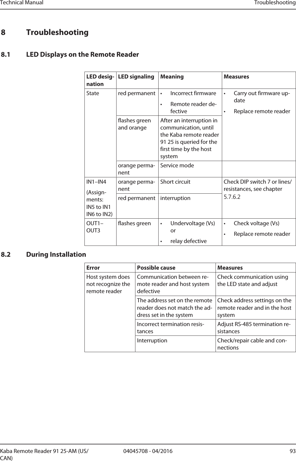
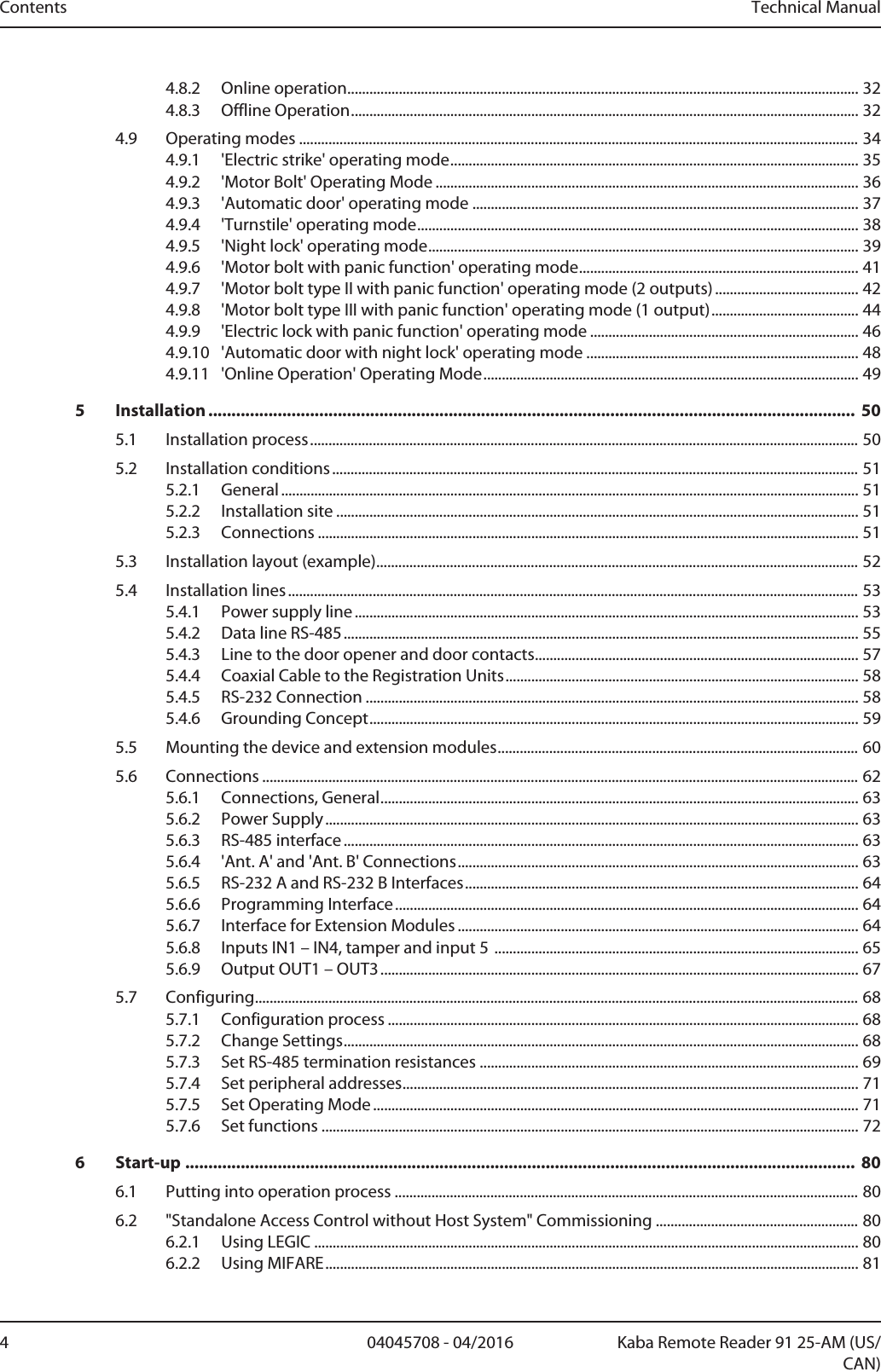
![Design and function Technical Manual30 04045708 - 04/2016 Kaba Remote Reader 91 25-AM (US/CAN)4.7 LED DisplayThe LED display shows operating statuses and errors. Troubleshooting tips are listedin Chapter [}8].LED Designation LED Behavior MeaningState green permanent Device in operation (off-line)flashes green RS-485 interface in the re-ceive or send mode (on-line)orange permanent Service modered permanent or off Device defectiveflashes green and orange After an interruption incommunication, until thedevice is queried for thefirst time by the host sys-temIN1–IN4 green permanent LED lights once the corre-sponding input is enabledorange flashing Service modeorange permanent or off Update via programmer1460IN1–IN4Monitoring enabledorange permanent Short circuitred permanent interruptionOUT1–OUT3 green permanent the relevant output is ac-tiveflashes green Undervoltage (Vs) or relaydefectivered permanent Write/read authorization(launch data) is deletedOUT1 red permanent Input 5 (only in Kaba exoslock operating mode)As soon as the door han-dle contact is active](https://usermanual.wiki/dormakaba-EAD/KRR9125-K5/User-Guide-3156567-Page-30.png)
![Design and function Technical Manual32 04045708 - 04/2016 Kaba Remote Reader 91 25-AM (US/CAN)4.8.2 Online operationIn online operation, the Remotereader communicates with the host system. The sys-tem makes the access decision on the basis of badges, time-dependent authorizationand verification. The system controls the access points. If communication betweenRemotereader and system is interrupted, then the Remotereader independentlyswitches into offline operation. If the Remotereader is queried by the system again,then the Remotereader switches back into online operation.4.8.3 Offline OperationEven in offline operation, i.e. without communication with the host system, an accesspoint is monitored and controlled by the Remotereader. For access decisions, site keys are used under MIFARE and segment search keys are used under LEGIC. The Remotereader controls access points in accordance with the operating mode,door configuration and the corresponding 'extended functions' (offline configura-tion). In order to ensure fault-free offline operation, the Remotereader should be operatedwith a secure power supply (e.g. UPS).Offline operation can be turned off in the system and/or using the 'Mode' rotaryswitch (F = off). This means that the offline behavior defined in the hardware settingsis deactivated and the access point remains blocked if there is an interruption incommunication.Behavior in the event of an interruption to communication• The access point goes to the basic status (possibly alarm if the access point is notclosed)• Relays which are not involved in a door process (according to DIP switch) deacti-vate; the same is true for the connected Kaba extension module 9030.4.8.3.1 Offline Access DecisionThe customer determines the nature of the offline access decision which is parame-terized in the system. We differentiate the following offline access decisions:Parameter settings in the system: no offline access decisionThe Remotereader rejects all bookings in offline operation.Parameter settings in the system: Checking site key (MIFARE)/segment search key (LEGIC)In the online mode, the site key (MIFARE)/segment search key (LEGIC) is sent to theRemotereader by the system and saved in the Remotereader. During the offlinemode, the Remotereader only checks the site key (MIFARE)/segment search key(LEGIC). The time zone is not considered for this kind of access decision.LogbookThe logbook records and saves a maximum of 2000 events during the offline opera-tion. Once the Remotereader is online again, the saved data is sent to the host sys-tem and deleted from the memory of the Remotereader.The following events are logged:• Authorized accesses (incl. type of authorization)• Tampering, door forced open, door opener keyIf there are more than 2000 entries, the oldest will be overwritten (ring memory).Service modeSee chapter Service mode [}7.3]](https://usermanual.wiki/dormakaba-EAD/KRR9125-K5/User-Guide-3156567-Page-32.png)
![Technical Manual Design and function3304045708 - 04/2016Kaba Remote Reader 91 25-AM (US/CAN)Also see about this27.3Service mode [}87]](https://usermanual.wiki/dormakaba-EAD/KRR9125-K5/User-Guide-3156567-Page-33.png)
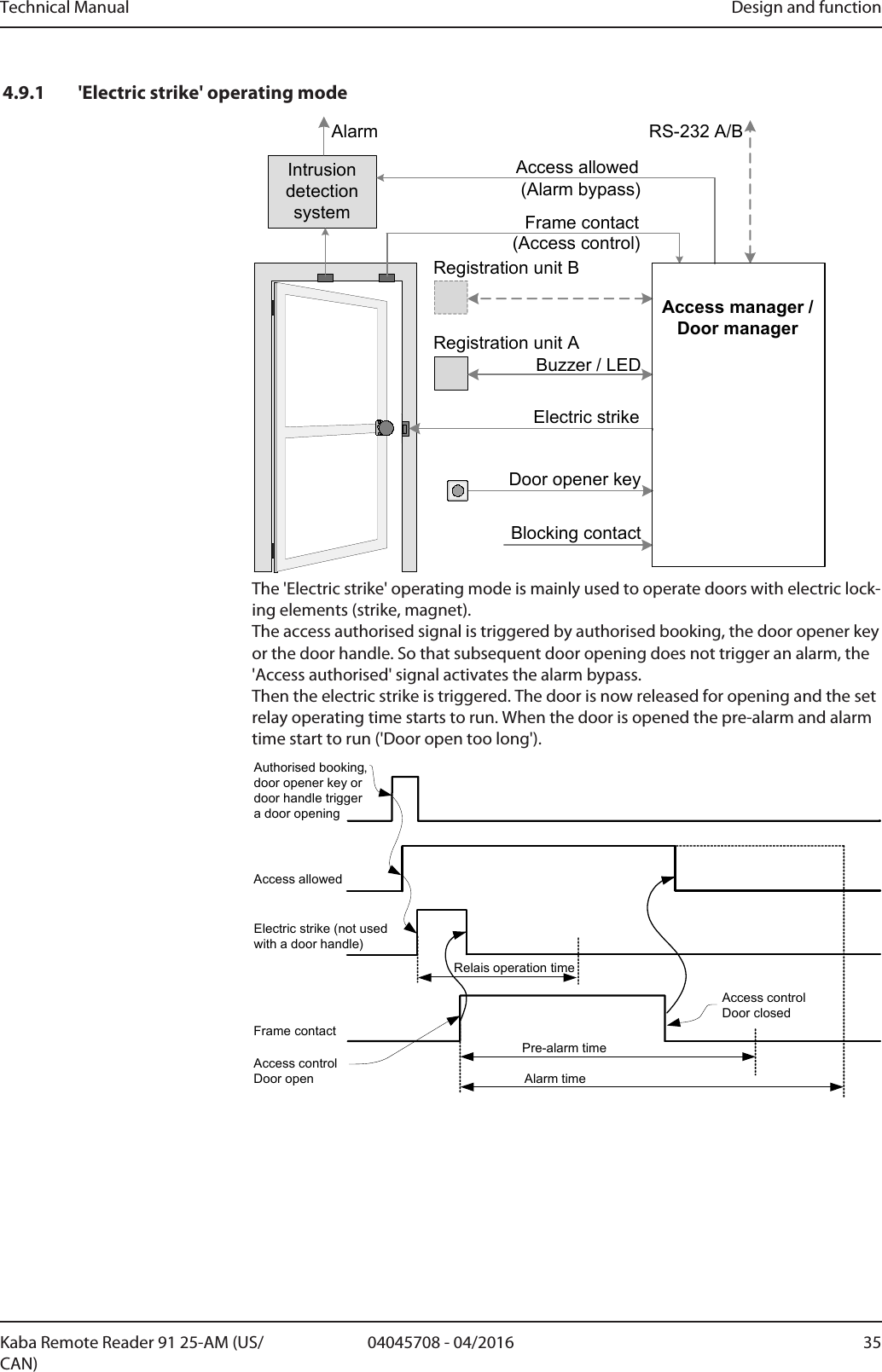
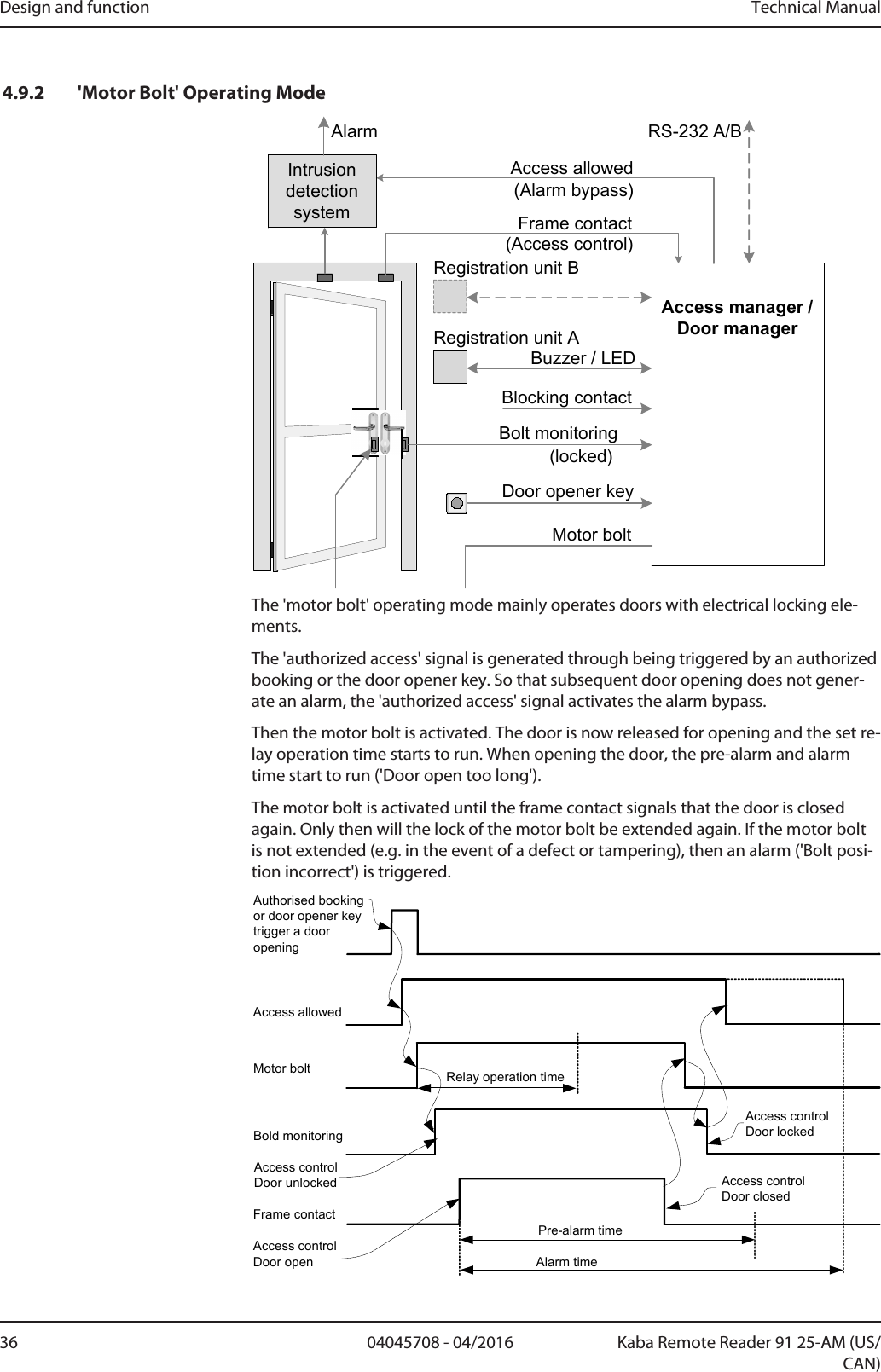
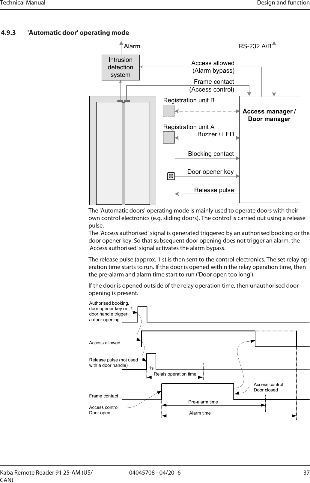
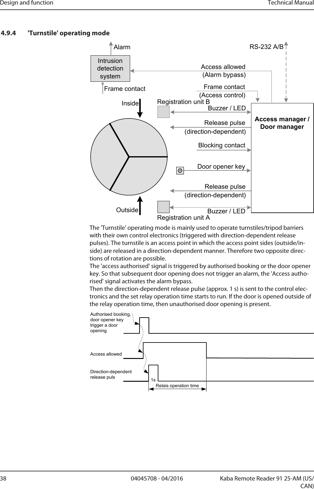
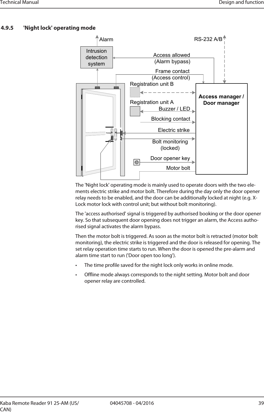
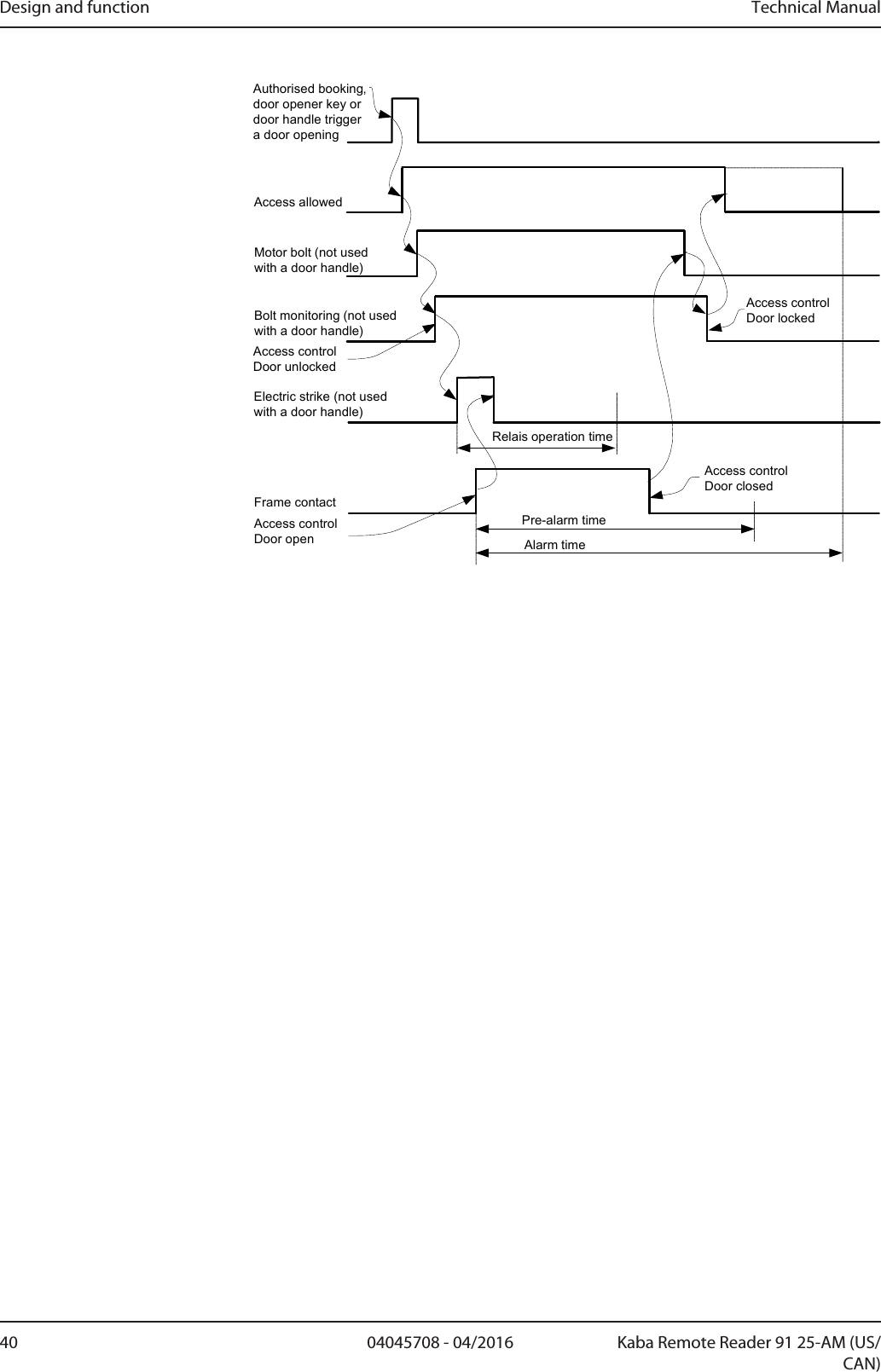
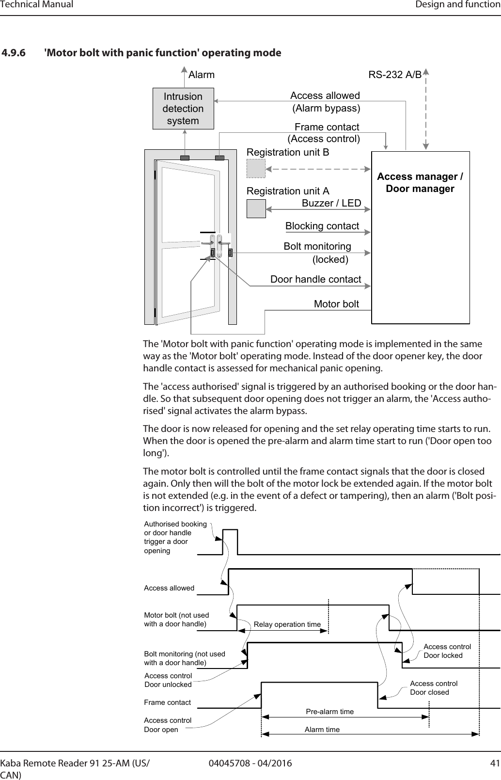
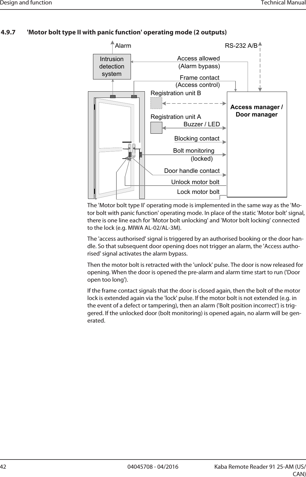
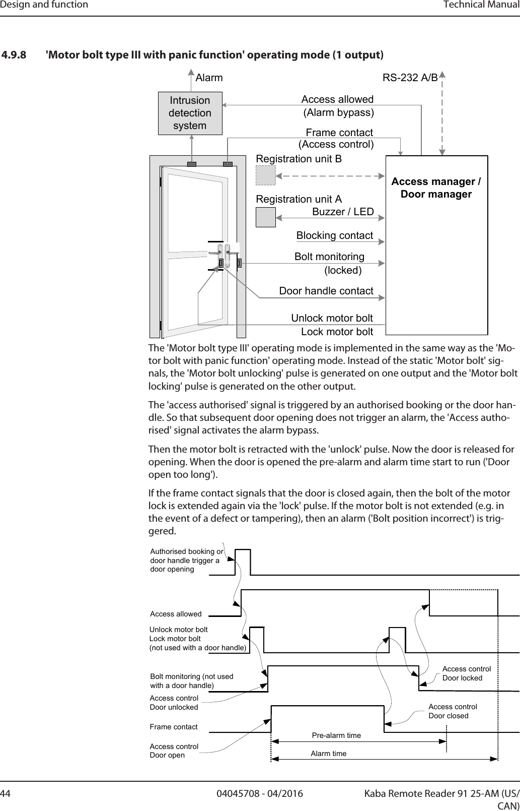
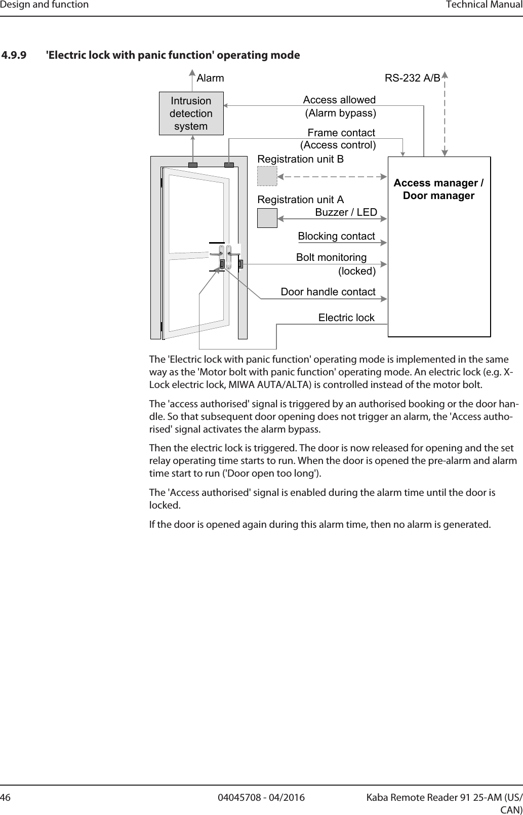
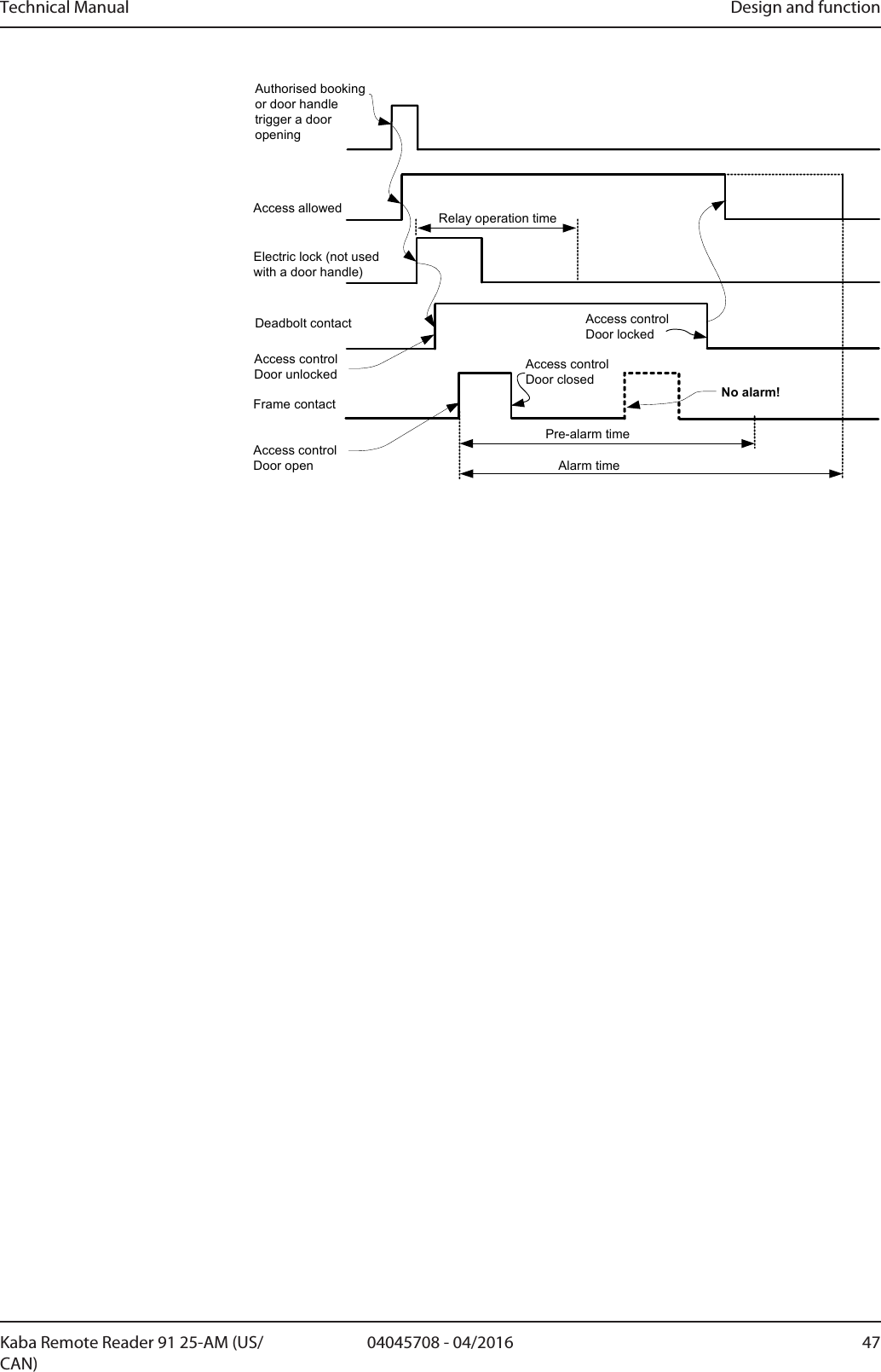
![Design and function Technical Manual34 04045708 - 04/2016 Kaba Remote Reader 91 25-AM (US/CAN)4.9 Operating modesThe operating mode of the Remotereader must be selected on the basis of the doorconfiguration.The operating mode is set using the rotary switch, see Chapter Set Operating Mode.The extended functions of a selected operating mode are set using the DIP switchExtended functions of the operating modes [}5.7.6.1].Possible operating modes:• Electric strike; for doors with electrical blocking elements• Motor bolt; for doors with electrical blocking elements• Automatic doors; for doors with their own electronic control system (control withenable pulse; e.g. sliding door)• Turnstile; for turnstiles/tripod turnstiles with their own electronic control system(control with direction-dependent enable pulses)• Night lock; for doors with the two elements electronic strike and motor bolt• Kaba exos lock; for doors with self-locking Kaba panic locks;• Cylinder interface LI-EL; for doors with mechatronic Kaba elolegic cylinders• Motor bolt with panic function; for doors with electrical blocking elements andadditional mechanical panic opening• Motor bolt type II with panic function (two outputs); for doors with electricalblocking elements and additional mechanical panic opening. 1 output each forthe pulses 'unlock' and 'lock'.• Motor bolt type III with panic function (1 output); for doors with electrical block-ing elements and additional mechanical panic opening. 1 output for the pulses'unlock' and 'lock'.• Electric lock with panic function; for doors with electrical blocking elements andadditional mechanical panic opening• Automatic door with night lock for doors with their own electronic control sys-tem and additional night lockAlso see about this24.9.1'Electric strike' operating mode [}35]](https://usermanual.wiki/dormakaba-EAD/KRR9125-K5/User-Guide-3156567-Page-34.png)
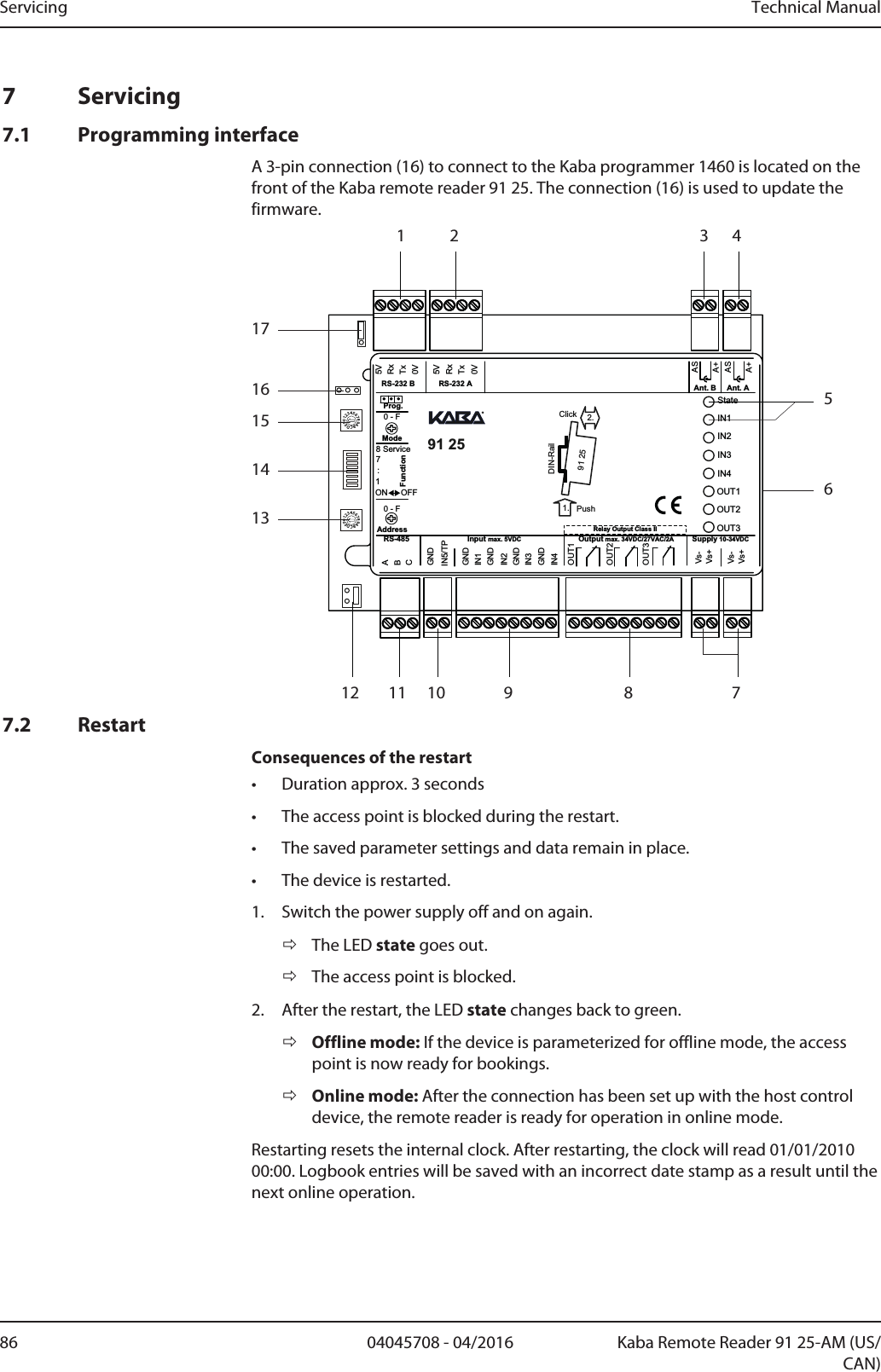
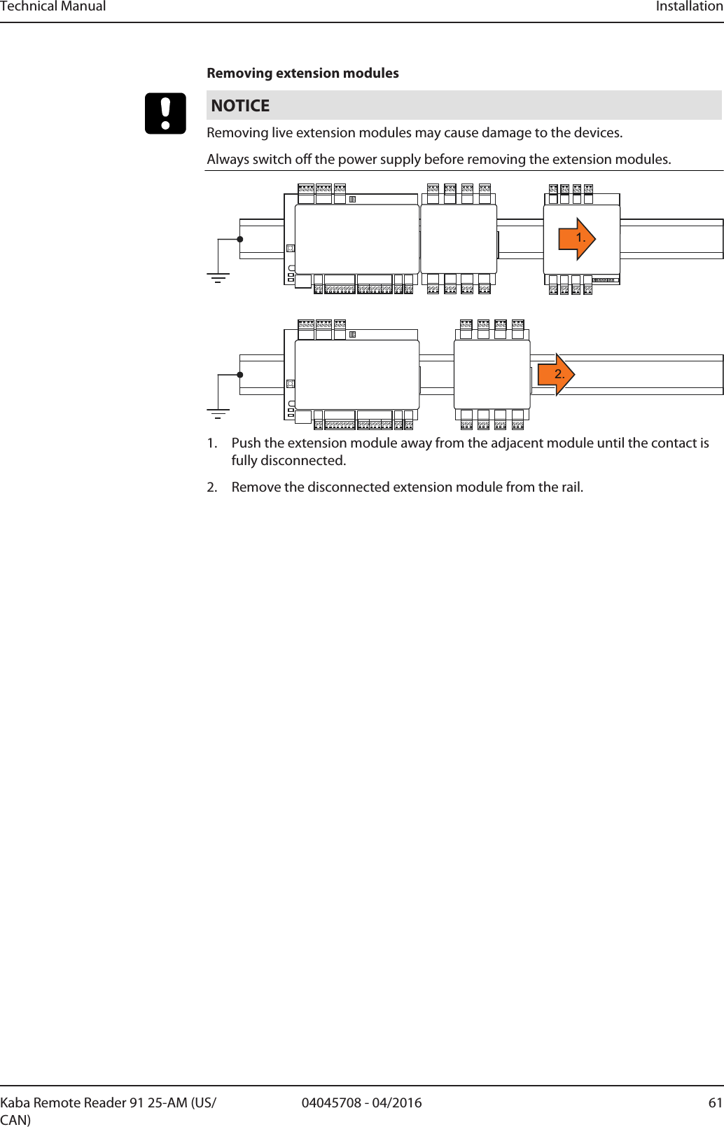
![Installation Technical Manual50 04045708 - 04/2016 Kaba Remote Reader 91 25-AM (US/CAN)5 InstallationThis chapter describes the installation of the device.5.1 Installation processProcedure1. Determine the installation site.Installation site [}5.2.2]2. Lay the installation cables.Installation lines [}5.4]3. Secure the device.4. Connect registration units.'Ant. A' and 'Ant. B' Connections [}5.6.4], Coaxial Cable to the Registration Units [}5.4.4],Coaxial Cable Terminal [}5.4.6.4]5. Check read behavior without system configuration:Book with an ISO 14443 A medium or Legic Prime medium.ðIf the medium can be read, the registration unit signals this as unauthorizedaccess.6. Connect keypads or system-dependent functions.RS-232 A and RS-232 B Interfaces7. Connect the inputs.Inputs IN1 – IN4, tamper and input 5 [}5.6.8]8. Connect the relay outputs.Output OUT1 – OUT3 [}5.6.9]9. Plug in/connect extension modules where required.10. Connect Kaba remote reader 91 25 and host device to the RS-485 bus cable. RS-485 interface [}5.6.3]Configure the device after installation.Configuring [}5.7]Also see about this25.5Mounting the device and extension modules [}60]25.4Installation lines [}53]25.7Configuring [}68]](https://usermanual.wiki/dormakaba-EAD/KRR9125-K5/User-Guide-3156567-Page-50.png)
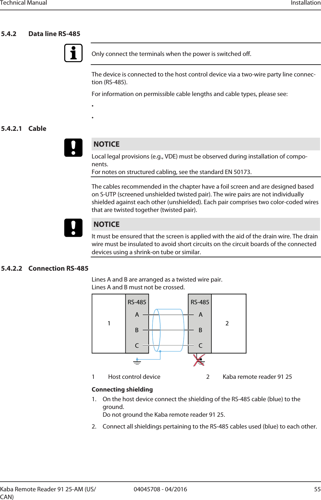
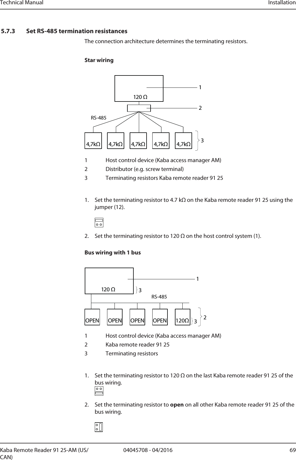
![Installation Technical Manual56 04045708 - 04/2016 Kaba Remote Reader 91 25-AM (US/CAN)5.4.2.3 Using several remote readersIf several Kaba remote reader 91 25 are to be connected to a host control device, ei-ther bus wiring or star wiring can be used.See:• Star wiring• Bus wiring5.4.2.4 Star wiringMax. eight devices can be operated on a party line.Power supply and data line in one cable: Maximum cable length per remote reader orstub: 20mPower supply and data line in separate cables: Maximum data line length per remotereader or stub: 100m4,7kΩ4,7kΩ4,7kΩ 4,7kΩ4,7kΩ120 ΩRS-4852131 Host control device (Kaba access manager)2 Distributor (e.g. screw terminal)3 Kaba remote reader 9125See alsoConnection RS-485 [}5.4.2.2]Set RS-485 termination resistancesSet peripheral addresses [}5.7.4]](https://usermanual.wiki/dormakaba-EAD/KRR9125-K5/User-Guide-3156567-Page-56.png)
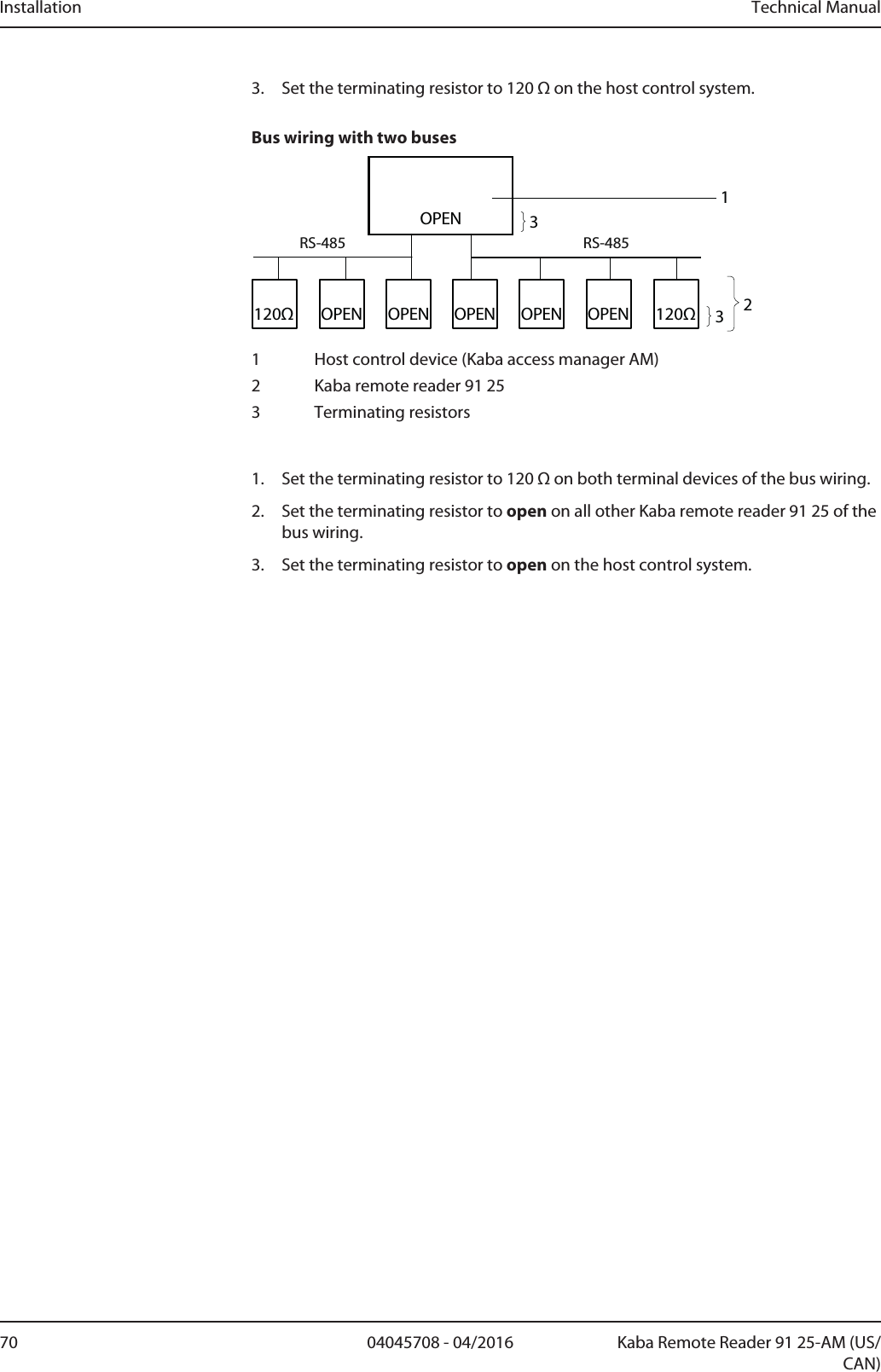
![Technical Manual Installation5704045708 - 04/2016Kaba Remote Reader 91 25-AM (US/CAN)5.4.2.5 Bus wiringA maximum of eight devices can be operated on a party line.Maximum total length of data lines (incl. stubs): 1200m A stub itself may be a maximum of 100m in length. The length of the party line can be increased using a repeater.5.4.2.5.1 Bus wiring with 1 bus120ΩOPENOPENOPENOPENRS-485120 Ω12331 Host control device (Kaba access manager)2 Kaba remote reader 91 253 Terminating resistorsSee alsoConnection RS-485 [}5.4.2.2]Set RS-485 termination resistancesSet peripheral addresses [}5.7.4]5.4.2.5.2 Bus wiring with two buses120Ω120ΩRS-485RS-485OPEN233OPEN OPENOPENOPENOPEN11 Host control device (Kaba access manager)2 Kaba remote reader 91 253 Terminating resistorsSee alsoConnection RS-485 [}5.4.2.2]Set RS-485 termination resistancesSet peripheral addresses [}5.7.4]5.4.3 Line to the door opener and door contactsLine requirements: Cable diameters from 0.5 mm to 0.8 mm.Recommended cable: CAT.5 S-UTP 4 x 2 AWG 24 or AWG 22 (according to EIA/TIA568) or higher.](https://usermanual.wiki/dormakaba-EAD/KRR9125-K5/User-Guide-3156567-Page-57.png)
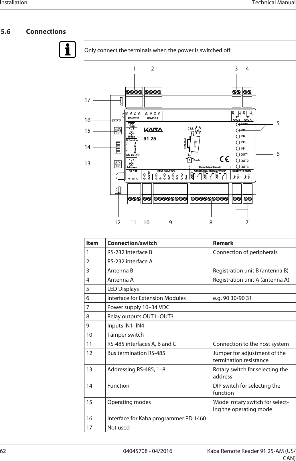
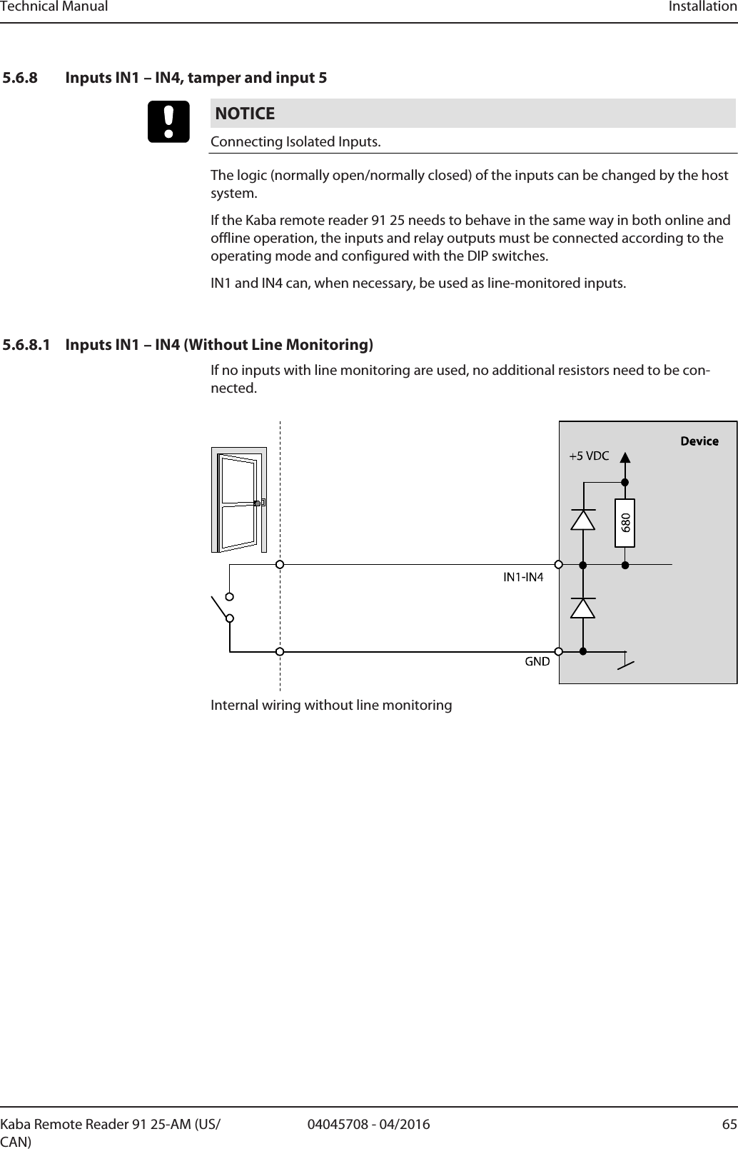
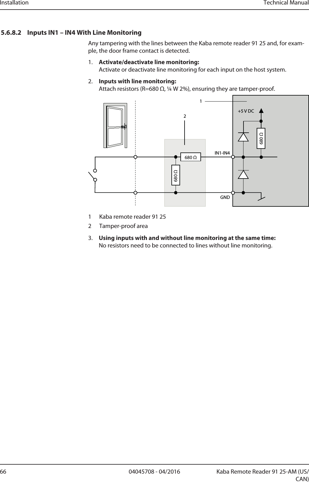
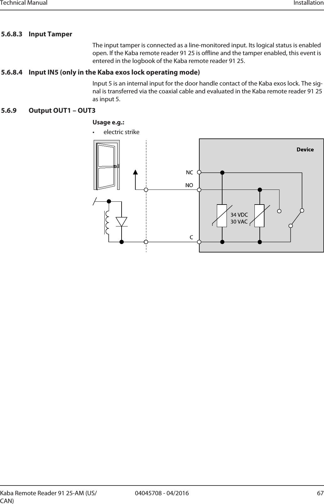
![Technical Manual Installation6304045708 - 04/2016Kaba Remote Reader 91 25-AM (US/CAN)The functions and connections of the interfaces, inputs, relay outputs, rotary and DIPswitches are described in the chapterConnecting.5.6.1 Connections, GeneralOnly connect the terminals when the power is switched off.Connection Type Connection OccupancyPluggable screw terminals The occupancy of the connection termi-nals can be taken from the following ta-bles5.6.2 Power Supply2 x 2 clamps are available for the power supply. These are connected in parallel.Terminal MeaningSupply Vs+ 10–34VDC Current consumption max. 330mA, withoutexternal wiringSupply Vs- 0VDCSupply voltage forRS-232 and extensionmodules at 25°C5VDC, max. 1AThe device may only be supplied with SELV (Safety Extra Low Voltage) and LPS (Lim-ited Power Source), according to IEC/UL/CSA 60950-1.5.6.3 RS-485 interfaceThe device communicates with the host system (access hub) via the RS-485 interface.Terminal MeaningA RS-485 wire AB RS-485 wire BC RS-485 wire C (Common)Set RS-485 termination resistancesSet peripheral addresses [}5.7.4]5.6.4 'Ant. A' and 'Ant. B' ConnectionsThe connections 'Ant. A' and 'Ant. B' are for the connection of the registration units tothe device. Coaxial cables are used for the connection. LED and acoustic signal trans-mitter of the registration unit are controlled via the coaxial cable.Terminal MeaningA+ Antenna cable inner conductorAS Antenna cable shield wire](https://usermanual.wiki/dormakaba-EAD/KRR9125-K5/User-Guide-3156567-Page-63.png)
![Installation Technical Manual64 04045708 - 04/2016 Kaba Remote Reader 91 25-AM (US/CAN)5.6.5 RS-232 A and RS-232 B InterfacesThe required power supply is provided via the Kaba remote reader 91 25.Terminal Meaning5V 5VDCRx RXD (Receive/in)Tx TXD (Transmit/out)0V 0VFurther information about the system-dependent functions:• System documentation5.6.6 Programming InterfaceFor connecting the Kaba programmer.Usage:• Firmware update, see Chapter Firmware Update/LEGIC OS Update5.6.7 Interface for Extension ModulesFor the connection of:• Kaba extension module 90 30• Kaba extension module 90 31Number of Supported Extension Modules [}3.5.1]Also see about this23.5.1Number of Supported Extension Modules [}18]](https://usermanual.wiki/dormakaba-EAD/KRR9125-K5/User-Guide-3156567-Page-64.png)
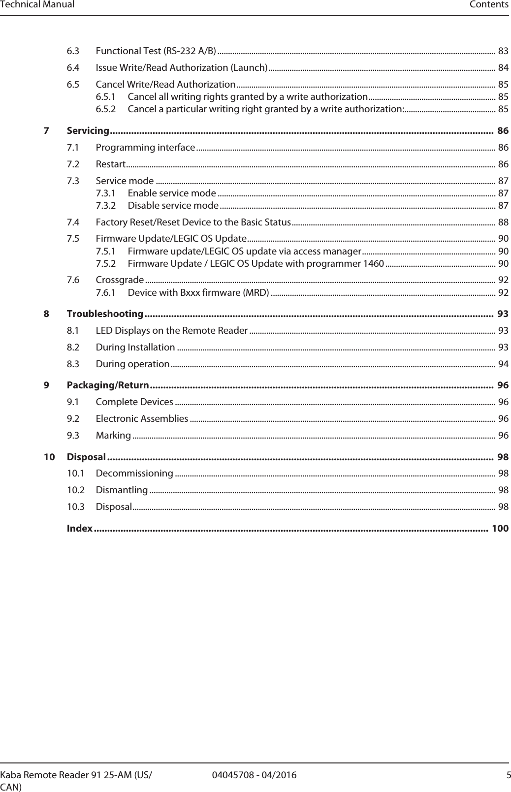
![Installation Technical Manual68 04045708 - 04/2016 Kaba Remote Reader 91 25-AM (US/CAN)5.7 Configuring5.7.1 Configuration process1. Set address of the Kaba remote reader 91 25, see chapterAddressing. Note down the address. It is required for the configuration in the host system.2. Set termination resistance on the RS-485 bus as per the bus topology, see chap-ter Bus termination RS-4853. Set operating mode according to the door configuration, see chapterSet Operating Mode4. Set extended functions for the selected operating mode, see chapter Extended functions of the operating modes [}5.7.6.1]5. Activate or deactivate monitoring of all inputs, see chapter Activate monitoring of all inputs (DIP switch 7)5.7.2 Change SettingsJumper, DIP switch and rotary switch settings must only be made when the power isswitched off.Changes of jumper-, DIP switch- and rotary switch settings are only activated afterturning on the power supply (cold start).0123456789ABCDEF0123456789ABCDEFMode718 ServiceON OFFGNDGNDGNDGNDGNDStateIN1IN2IN3IN4OUT1OUT2OUT35VRxTxRxTx0VIN5/TPIN1IN2IN3IN4Vs-Vs-Vs+Vs+FunctionOUT1OUT2OUT3ABCSupply 10-34VDCOutput max. 34VDC/27VAC/2AInput max. 5VDCRS-4855V0VRS-232 B RS-232 A Ant. B Ant. AASA+ASA+:AddressProg.Relay Output Class II91 25 2.1. PushClickDIN-Rail91 250 - F0 - F8 75613141516171 2 3 49101112](https://usermanual.wiki/dormakaba-EAD/KRR9125-K5/User-Guide-3156567-Page-68.png)
![Technical Manual Installation7104045708 - 04/2016Kaba Remote Reader 91 25-AM (US/CAN)5.7.4 Set peripheral addressesEach device connected to an RS-485 bus must have a unique address.1. Assign the Kaba remote reader 91 25 with rotary switch (13) a unique peripheraladdress.Position Peripheral address Position Peripheral address0 Default, not used 5 51 1 6 62 2 7 73 3 8 84 4 9–F Not used5.7.5 Set Operating ModeThe door configuration determines the operating mode of the Kaba remote reader91 25. The operating mode is set with the rotary switch (15).In order to define the offline behavior of the device, the "extended functions" mustbe set in addition to the operating mode. The Chapter [}5.7.6.1] explains the ex-tended functions.Kaba remote reader 91 25PositionRotary switchOperating mode0 Electric strike1 Motor bolt2 Automatic door3 Turnstile4 Night lock5 Kabaexos lock6 Cylinder interface LI-EL7 Motor bolt with panic function8 Motor bolt type II with panic function (2outputs)9 Motor bolt type III with panic function (1output)A Electric lock with panic functionB Automatic door with night lockC–E Not usedF Online operationThe chapter Operating modes [}4.9] describes the operating modes.](https://usermanual.wiki/dormakaba-EAD/KRR9125-K5/User-Guide-3156567-Page-71.png)
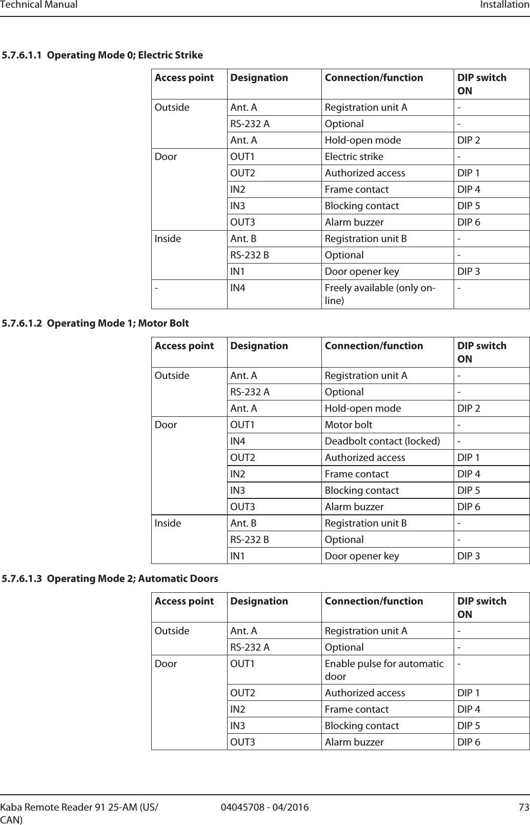
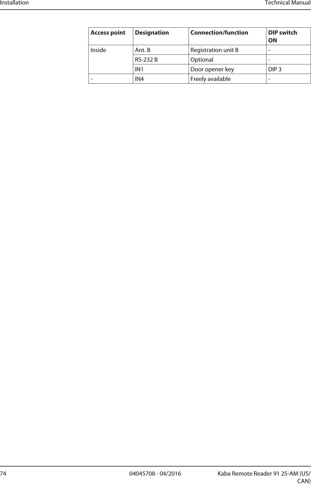
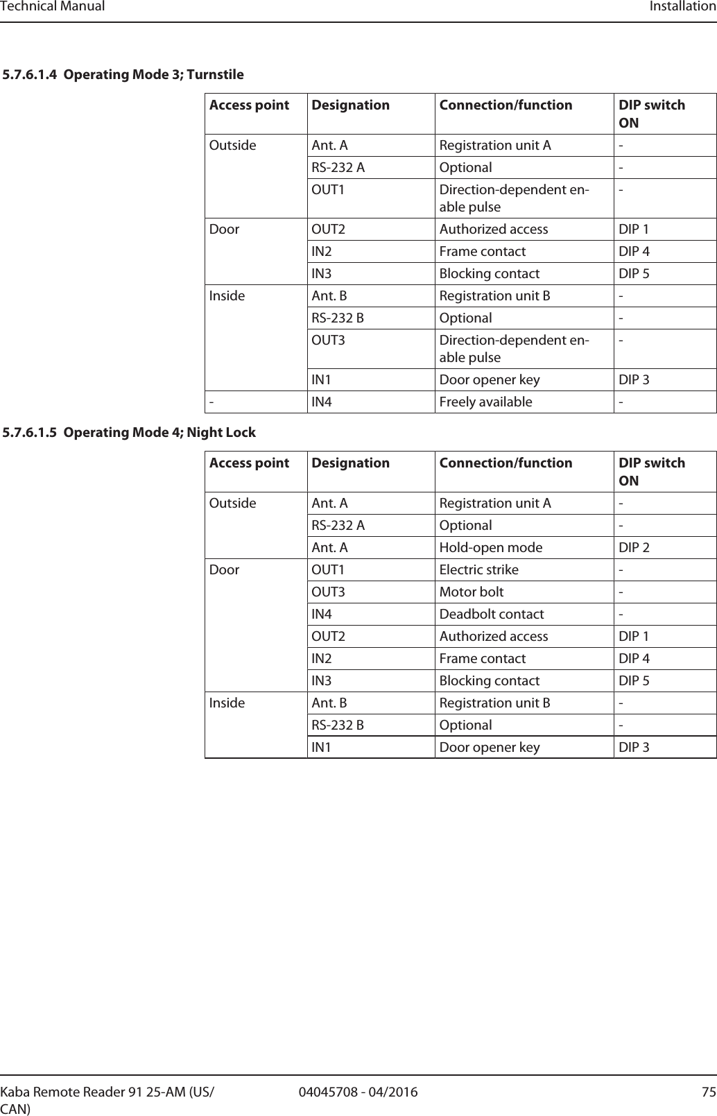
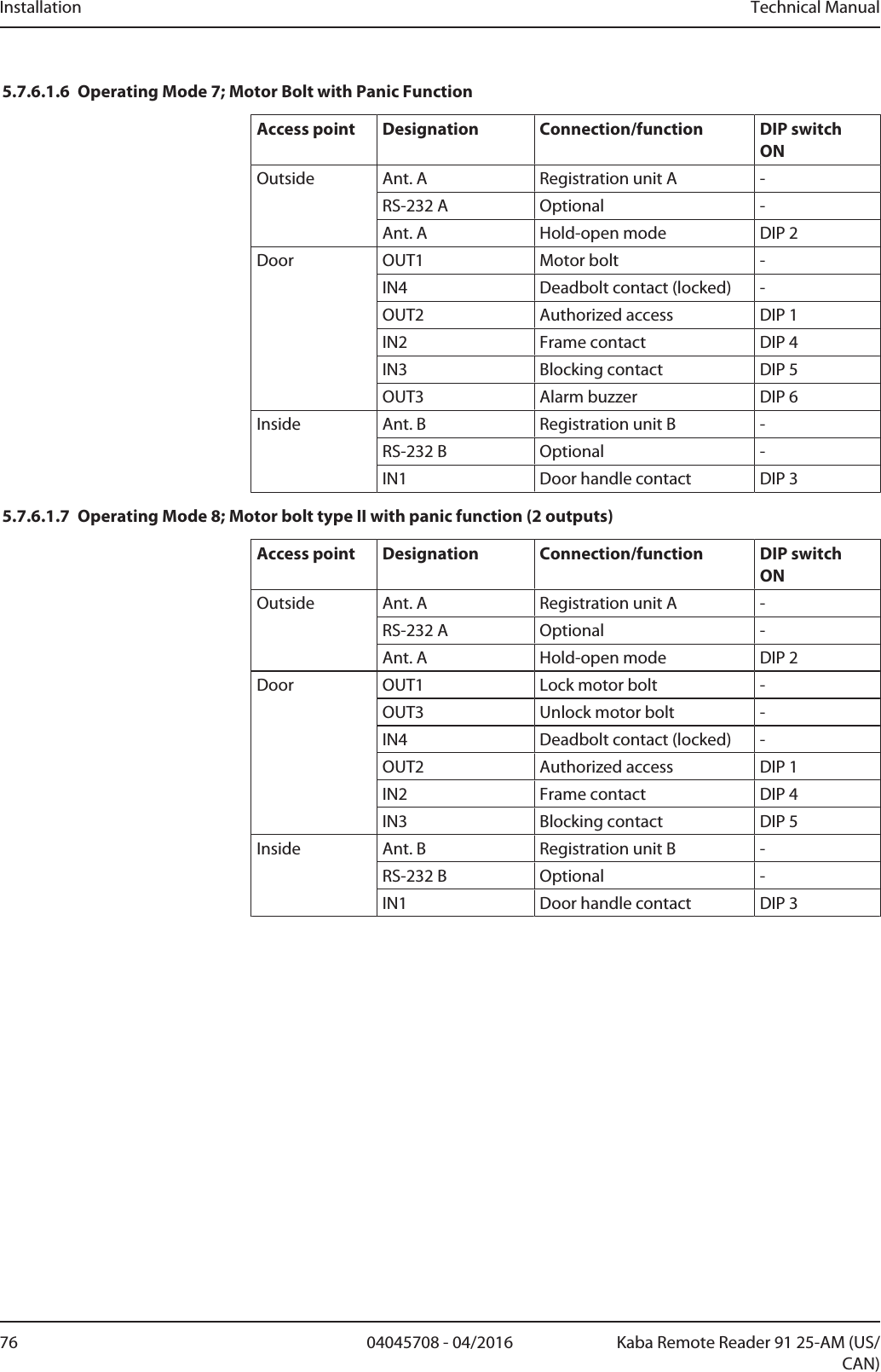
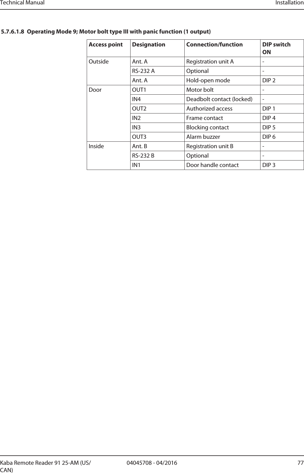
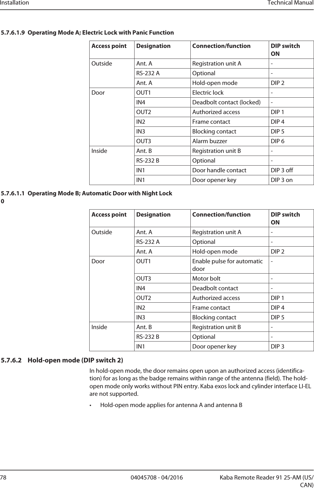
![Installation Technical Manual72 04045708 - 04/2016 Kaba Remote Reader 91 25-AM (US/CAN)5.7.6 Set functionsThe following functions can be set with the DIP switches (14):DIP switch NumberFunction1–6 Extended functions (according to operating modes)7 Not used8 ON Service mode5.7.6.1 Extended functions of the operating modesThe DIP switches 1–6 (14) are used to set the extended functions of the operatingmodes.The chapter Operating modes describes the operating modes.If the Kaba remote reader 91 25 needs to behave in the same way in both online andoffline operation, the inputs and relay outputs must be connected according to theoperating mode and configured with the DIP switches.The parameterization of the access point must match the selected configuration inthe host system. See also chapter Operating Types [}4.8]NOTICEThe DIP switches should only be put to ON if the relevant component is also con-nected to the device.The following chapters describe the individual operating modes with their connec-tions and configurations.](https://usermanual.wiki/dormakaba-EAD/KRR9125-K5/User-Guide-3156567-Page-72.png)
![Start-up Technical Manual80 04045708 - 04/2016 Kaba Remote Reader 91 25-AM (US/CAN)6 Start-up6.1 Putting into operation processüThe device is installed.Installation process [}5.1]üThe device is configured.Configuring1. Reset device to its basic state.Factory Reset/Reset Device to the Basic Status2. Connect the power supply to the Kaba remote reader 91 25, see chapterPower Supply [}5.6.2]ðLED state illuminates green – LED state flashes green as soon as the RS-485interface is in the receive or send mode (online).3. Put the device into operation in accordance with the following chapter.6.2 "Standalone Access Control without Host System" Commissioning(Construction site mode)The Remotereader can already be used on a host system even before connection.This allows for the use of the remote reader, e.g., during the construction phase.By connecting the remote reader to a host control device (host system), the func-tions of the remote reader described in this chapter are replaced by parameteriza-tion of the system.Also see about this21.4Supplementary Documents [}8]6.2.1 Using LEGICIf using "Standalone access control (without host system)", only the LEGIC stamp(segment search key) is checked. To authorize access, the user medium's stamp mustmatch the stamp of the remote reader.• If using "Standalone access control (without host system)" the remote reader canonly be used with one stamp (segment search key).Preparation1. Use security cardC1 (IAM) to define the stamp of masterA (only LEGIC ISO14443A) (see RM_LEGIC_advant_Media_Definition).Putting into operation1. Carry out factory reset on the remote reader, see Chapter2. Present Master A (only LEGIC ISO 14443A) to the connected registration unit.ðIn the event of successful transfer of the stamp: 3x short beepðThe stamp (segment search key) was transferred onto the remote reader.ðThe remote reader is now ready for bookings.Functions• Book• Save the following events (max. 2000):– Door forced open](https://usermanual.wiki/dormakaba-EAD/KRR9125-K5/User-Guide-3156567-Page-80.png)