dormakaba EAD KRR9125-K5 Desktop Reader User Manual TM RemoteReader9125 AM US CAN 201603 en
Kaba GmbH Desktop Reader TM RemoteReader9125 AM US CAN 201603 en
user manual

Kaba Remote Reader 91 25-AM (US/CAN)
Technical Manual
EN
04045708 - 04/2016

Kaba AG
Access & Workforce Management
Hofwisenstrasse 24
8153 Rümlang
Switzerland
Phone +41 44 818 93 11
www.kaba.com
Kaba AG
Access & Workforce Management
Mühlebühlstrasse 23
8620 Wetzikon
Switzerland
Phone +41 44 931 61 11
www.kaba.com
Kaba GmbH
Access & Workforce Management
Albertistraße 3
78056 Villingen-Schwenningen
Germany
Phone +49 7720 603 0
www.kaba.com
This document must not be reproduced in any way or otherwise further used without the written consent of Kaba AG.
All product names are trademarks of the respective companies.
Copyright 2016 Kaba AG. All rights reserved.
04045708 - 04/2016

Technical Manual Contents
Kaba Remote Reader 91 25-AM (US/
CAN)
304045708 - 04/2016
Contents
1 About this Document ............................................................................................................................. 7
1.1 Validity............................................................................................................................................................................... 7
1.2 Target group ................................................................................................................................................................... 7
1.3 Contents and purpose................................................................................................................................................. 7
1.4 Supplementary Documents ...................................................................................................................................... 8
1.5 Change Log ..................................................................................................................................................................... 8
1.6 Orientation in the Document.................................................................................................................................... 8
1.7 Abbreviations/Term Definitions .............................................................................................................................. 9
1.8 Warnings.........................................................................................................................................................................10
1.8.1 Hazard Categories........................................................................................................................................10
1.8.2 Symbols............................................................................................................................................................10
1.9 Notes................................................................................................................................................................................10
2 Grouped safety messages.................................................................................................................... 11
2.1 Use as directed .............................................................................................................................................................11
2.2 Mounting and Installation........................................................................................................................................11
2.3 Service and Maintenance .........................................................................................................................................11
2.4 Accessories and spare parts ....................................................................................................................................11
2.5 ESD (electrostatic discharge) protective measures.........................................................................................12
3 Product Description ............................................................................................................................. 13
3.1 Overview.........................................................................................................................................................................13
3.2 Registration Unit Compatibility .............................................................................................................................14
3.3 Operating modes ........................................................................................................................................................15
3.4 Supported RFID Standards with Possible Media Definitions.......................................................................16
3.4.1 MIFARE .............................................................................................................................................................16
3.4.2 LEGIC.................................................................................................................................................................16
3.5 Interface for Extension Modules ............................................................................................................................18
3.5.1 Number of Supported Extension Modules .........................................................................................18
3.6 Technical Data ..............................................................................................................................................................19
3.6.1 Overview of Technical Data......................................................................................................................19
3.6.2 Dimensions.....................................................................................................................................................21
3.7 Conformity.....................................................................................................................................................................22
3.8 Labeling ..........................................................................................................................................................................24
4 Design and function ............................................................................................................................. 25
4.1 Device structure...........................................................................................................................................................25
4.2 Firmware.........................................................................................................................................................................26
4.3 System Requirements................................................................................................................................................26
4.4 Behavior with two Registration Units ..................................................................................................................27
4.5 Behavior with Several Media in the Field (Anti-Collision).............................................................................27
4.6 Functions........................................................................................................................................................................28
4.7 LED Display....................................................................................................................................................................30
4.8 Operating Types ..........................................................................................................................................................31
4.8.1 Overview of Operating Types ..................................................................................................................31

Contents Technical Manual
4 Kaba Remote Reader 91 25-AM (US/
CAN)
04045708 - 04/2016
4.8.2 Online operation...........................................................................................................................................32
4.8.3 Offline Operation..........................................................................................................................................32
4.9 Operating modes ........................................................................................................................................................34
4.9.1 'Electric strike' operating mode...............................................................................................................35
4.9.2 'Motor Bolt' Operating Mode ...................................................................................................................36
4.9.3 'Automatic door' operating mode .........................................................................................................37
4.9.4 'Turnstile' operating mode........................................................................................................................38
4.9.5 'Night lock' operating mode.....................................................................................................................39
4.9.6 'Motor bolt with panic function' operating mode............................................................................41
4.9.7 'Motor bolt type II with panic function' operating mode (2 outputs) .......................................42
4.9.8 'Motor bolt type III with panic function' operating mode (1 output)........................................44
4.9.9 'Electric lock with panic function' operating mode .........................................................................46
4.9.10 'Automatic door with night lock' operating mode ..........................................................................48
4.9.11 'Online Operation' Operating Mode......................................................................................................49
5 Installation ............................................................................................................................................ 50
5.1 Installation process.....................................................................................................................................................50
5.2 Installation conditions...............................................................................................................................................51
5.2.1 General.............................................................................................................................................................51
5.2.2 Installation site ..............................................................................................................................................51
5.2.3 Connections ...................................................................................................................................................51
5.3 Installation layout (example)...................................................................................................................................52
5.4 Installation lines...........................................................................................................................................................53
5.4.1 Power supply line.........................................................................................................................................53
5.4.2 Data line RS-485............................................................................................................................................55
5.4.3 Line to the door opener and door contacts........................................................................................57
5.4.4 Coaxial Cable to the Registration Units................................................................................................58
5.4.5 RS-232 Connection ......................................................................................................................................58
5.4.6 Grounding Concept.....................................................................................................................................59
5.5 Mounting the device and extension modules..................................................................................................60
5.6 Connections ..................................................................................................................................................................62
5.6.1 Connections, General..................................................................................................................................63
5.6.2 Power Supply.................................................................................................................................................63
5.6.3 RS-485 interface ............................................................................................................................................63
5.6.4 'Ant. A' and 'Ant. B' Connections.............................................................................................................63
5.6.5 RS-232 A and RS-232 B Interfaces...........................................................................................................64
5.6.6 Programming Interface..............................................................................................................................64
5.6.7 Interface for Extension Modules .............................................................................................................64
5.6.8 Inputs IN1 – IN4, tamper and input 5 ...................................................................................................65
5.6.9 Output OUT1 – OUT3..................................................................................................................................67
5.7 Configuring....................................................................................................................................................................68
5.7.1 Configuration process ................................................................................................................................68
5.7.2 Change Settings............................................................................................................................................68
5.7.3 Set RS-485 termination resistances .......................................................................................................69
5.7.4 Set peripheral addresses............................................................................................................................71
5.7.5 Set Operating Mode ....................................................................................................................................71
5.7.6 Set functions ..................................................................................................................................................72
6 Start-up ................................................................................................................................................. 80
6.1 Putting into operation process ..............................................................................................................................80
6.2 "Standalone Access Control without Host System" Commissioning .......................................................80
6.2.1 Using LEGIC ....................................................................................................................................................80
6.2.2 Using MIFARE.................................................................................................................................................81

Technical Manual Contents
Kaba Remote Reader 91 25-AM (US/
CAN)
504045708 - 04/2016
6.3 Functional Test (RS-232 A/B)...................................................................................................................................83
6.4 Issue Write/Read Authorization (Launch)...........................................................................................................84
6.5 Cancel Write/Read Authorization..........................................................................................................................85
6.5.1 Cancel all writing rights granted by a write authorization............................................................85
6.5.2 Cancel a particular writing right granted by a write authorization:...........................................85
7 Servicing................................................................................................................................................ 86
7.1 Programming interface.............................................................................................................................................86
7.2 Restart..............................................................................................................................................................................86
7.3 Service mode ................................................................................................................................................................87
7.3.1 Enable service mode ...................................................................................................................................87
7.3.2 Disable service mode..................................................................................................................................87
7.4 Factory Reset/Reset Device to the Basic Status................................................................................................88
7.5 Firmware Update/LEGIC OS Update.....................................................................................................................90
7.5.1 Firmware update/LEGIC OS update via access manager...............................................................90
7.5.2 Firmware Update / LEGIC OS Update with programmer 1460....................................................90
7.6 Crossgrade .....................................................................................................................................................................92
7.6.1 Device with Bxxx firmware (MRD) ..........................................................................................................92
8 Troubleshooting................................................................................................................................... 93
8.1 LED Displays on the Remote Reader ....................................................................................................................93
8.2 During Installation ......................................................................................................................................................93
8.3 During operation.........................................................................................................................................................94
9 Packaging/Return................................................................................................................................. 96
9.1 Complete Devices .......................................................................................................................................................96
9.2 Electronic Assemblies ................................................................................................................................................96
9.3 Marking ...........................................................................................................................................................................96
10 Disposal................................................................................................................................................. 98
10.1 Decommissioning .......................................................................................................................................................98
10.2 Dismantling ...................................................................................................................................................................98
10.3 Disposal...........................................................................................................................................................................98
Index .................................................................................................................................................... 100

Contents Technical Manual
6 Kaba Remote Reader 91 25-AM (US/
CAN)
04045708 - 04/2016

Technical Manual About this Document
704045708 - 04/2016Kaba Remote Reader 91 25-AM (US/
CAN)
1 About this Document
1.1 Validity
This document describes all device versions and optional equipment and functions.
Options need to be paid for and are therefore only available if they have been pur-
chased. Additional equipment and functions may not yet be available at the time of
issuing the document and, possibly, can only be purchased at a later stage.
Product name: Kaba remote reader 91 25 (US / CAN)
Article number: 04044475
Functional type: AM (access manager)
Serial number:
Date of manufacture:
Firmware version from BREB03.05.RD_
Display in Kabaexos: BREB03.05.RD
1.2 Target group
This document is exclusively intended for specialist personnel.
The descriptions require specialist personnel trained by the manufacturer. The de-
scriptions do not replace product training.
For reasons of device safety, the installation and maintenance operations described
in this document must be carried out only by service persons according to EN
60950-1 (Information technology equipment - Safety).
Service persons are persons having adequate technical training and sufficient experi-
ence to be aware of and to minimize the possible risks for themselves or other per-
sons, which may occur when carrying out these operations. The service persons are
responsible for adhering to the instructions given by the manufacturer and to the ap-
plicable standards and regulations during execution of their work.
This document is also used as information for persons with the following tasks:
• project planning and implementation
• Commissioning the product within the network
• Connecting the product to the user software by programming customer applica-
tions
• Customer-specific adjustment by setting the parameters of the product
1.3 Contents and purpose
The contents is limited to the assembly, installation, start-up, and basic operation of
the hardware.
About this Document Technical Manual
8 04045708 - 04/2016 Kaba Remote Reader 91 25-AM (US/
CAN)
1.4 Supplementary Documents
Supplementary documentation is available on the Kaba website. The technical man-
uals are located in a secured area of the website.
• Access is only possible after logging in.
• An account will need to be created before logging in for the first time.
Access and login:
1. In the browser, access the Kaba page http://www.kaba.com.
2. Select the language in the top right.
3. Under "Products", select the "Access Management" or "Workforce Management"
product division.
4. In the top right section of the screen, click on the following symbol:
.
5. Enter your e-mail address and password and login or create an account (see be-
low).
ðThe technical manuals can be found under "Downloads".
Create account:
1. Click "Create account".
2. Complete the data fields and confirm.
ðA confirmation link will be sent to your e-mail address.
3. To activate your account, click on the confirmation link in your e-mail.
1.5 Change Log
The most important changes to the last issue of this manual are listed below:
Version number Edition Brief description
TM_RemoteReader9125-AM-US-
CAN_201603
03/2016 First edition (US /
CAN)
1.6 Orientation in the Document
This document contains the following orientation aids to facilitate finding of specific
topics:
• An index in the alphabetical order is given at the end of the manual.
• The table of contents at the beginning of the manual gives an overview of all
topics.
• The header always contains the respective main chapter.
• This step-by-step guide goes through the installation and commissioning.
• Cross references always indicate the number of the chapter in which the supple-
mentary information can be found. Example [ 5.7].

Technical Manual About this Document
904045708 - 04/2016Kaba Remote Reader 91 25-AM (US/
CAN)
1.7 Abbreviations/Term Definitions
Abbreviations and terms used in this document:
Abbreviation/
term
Term definition from 07/01/14
Remotereader Kaba remote reader 91 25
Device Kaba remote reader 91 25
Door manager Kaba remote reader 91 25
Registration unit Kaba registration unit 90 01
Kaba registration unit 90 02
Kaba registration unit 90 00
Antenna Registration unit
Extension module Kaba extension module 90 31
Kaba extension module 90 30
Host Host system
KCP Kaba Communication Protocol (RS-485)
BPA/9 subset Protocol for subterminal communication via RS-485 BPA =
Benzing Protocol Asynchronous
Control unit • Access manager or
• B-web terminal
KMM Kaba Media Manager
Access Manager Kaba access manager 92 00
KabaexosAMC Kabaexos AMCII
Programmer Kaba Programmer 1460
Authorized access Is active until the door is closed again or the alert duration has
expired
Door opener key Key which triggers single, authorized door opening
Door handle con-
tact
Contact in the door handle with which authorized door open-
ing is reported to the system
Frame contact Contact in the door frame with which the door status open or
closed is reported
Blocking contact Contact with which the access point can be blocked. In this
case, any identification on the registration unit is rejected as
access not authorized and signaled accordingly.
Alarm buzzer/alarm
relay
This signal is used to control the relay output if the door is
forced open or in the event of 'Door open too long'
Hold-open mode In the event of authorized access, the door remains activated
(opened) until the user medium is within the range (field) of
the antenna.
About this Document Technical Manual
10 04045708 - 04/2016 Kaba Remote Reader 91 25-AM (US/
CAN)
1.8 Warnings
Warnings containing information/instructions and prohibitions to prevent injury to
persons and damage to property are specially labeled.
Please pay attention to warnings. They are intended to help prevent accidents and
avoid damage.
1.8.1 Hazard Categories
Warnings are split into the following categories:
CAUTION
Slight Risk
Describes a potentially hazardous situation that could result in minor physical in-
juries.
NOTICE
Information on how to handle the product correctly.
Failure to comply with these warnings may result in malfunctions. The product or
something in its vicinity could be damaged.
1.8.2 Symbols
Depending on the source of the hazard, symbols are used for the warnings, and
these have the following meanings:
General danger Danger for electronic compo-
nents from electrostatic dis-
charge
1.9 Notes
Notes are labeled with an info symbol.
Tips and useful information.
These help you to make best use of the product and its functions.

Technical Manual Grouped safety messages
1104045708 - 04/2016Kaba Remote Reader 91 25-AM (US/
CAN)
2 Grouped safety messages
This product has been built in accordance with state-of-the-art standards and the
recognized safety rules. Nevertheless, its use may constitute a risk to persons and
cause damage to material property.
Read and observe the following safety instructions before using the product.
2.1 Use as directed
The product is only intended for use as described in chapter “Product description”.
Any use beyond that is considered contrary to its designated use. The manufacturer
cannot be held liable for damage resulting from such use. Such use is at the sole risk
of the user/operator.
2.2 Mounting and Installation
Mounting and installation may only be carried out by service persons (see chapter 1
“Target group”).
Installation may only be carried out in places that fulfill the climatic and technical
conditions stated by the manufacturer.
The manufacturer is not liable for damages resulting from improper handling or in-
correct installation.
2.3 Service and Maintenance
Maintenance work / troubleshooting
Only the service person (see chapter 1 “Target group”) is entitled to remove faults
and carry out maintenance work.
Reconstruction and modification
Any alteration or modification to the device may only be performed by the service
person (see chapter 1 “Target group”). Any alteration or modification performed by
unauthorized persons shall render void any liability.
2.4 Accessories and spare parts
Accessories and spare parts must comply with the technical requirements specified
by the manufacturer. This is guaranteed when using original accessories and spare
parts from Kaba.

Grouped safety messages Technical Manual
12 04045708 - 04/2016 Kaba Remote Reader 91 25-AM (US/
CAN)
2.5 ESD (electrostatic discharge) protective measures
NOTICE
Danger for electronic components due to electrostatic discharge.
Improper handling of printed circuit boards or components can cause damages that
lead to complete failures or sporadic errors.
• During installation and repair of the product, the ESD protective measures must
be considered.
• Wear an ESD wristband when handling electronic components. Connect the end
of the wristband to a discharge socket or an unvarnished grounded metal com-
ponent. This way, static charges are discharged from your body securely and ef-
fectively.
• Touch only the edges of circuit boards. Do not touch the circuit board nor the
connector.
• Place all dismantled components on an antistatic surface or in an antistatic con-
tainer.
• Avoid contact between circuit boards and clothing. The wristband only protects
the printed circuit boards against electrostatic discharge from your body, but
there is still a risk of damage through electrostatic discharge from your clothing.
• Transport and dispatch dismantled modules only in electrostatically shielded
protective bags.
Technical Manual Product Description
1304045708 - 04/2016Kaba Remote Reader 91 25-AM (US/
CAN)
3 Product Description
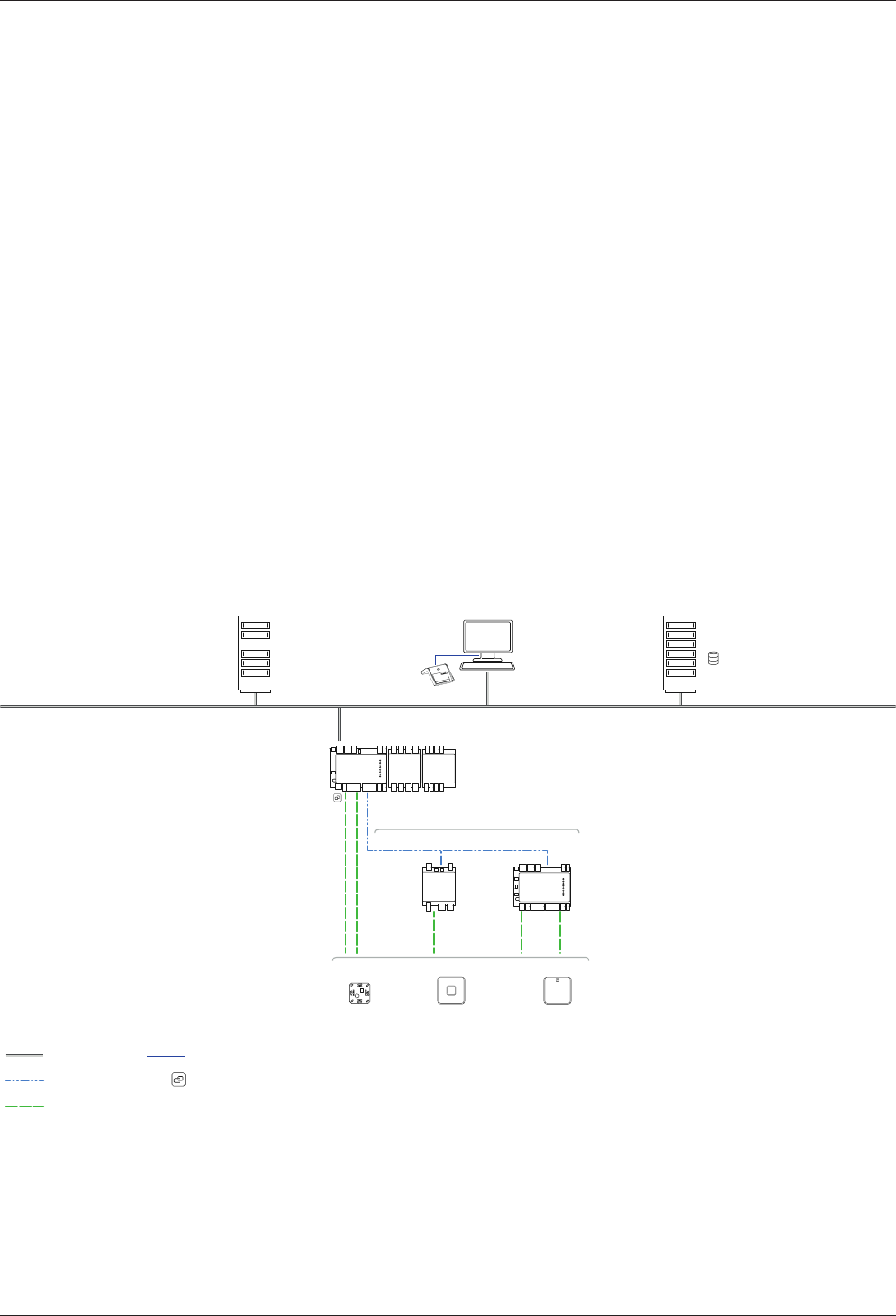
3.1 Overview
The Kaba remote reader 91 25 with functional type AM can either control and moni-
tor access control at access points or register coming/leaving bookings for time regis-
tration.
Two registration units can be connected to the Kaba remote reader 91 25. The re-
mote reader has two RS-232 interfaces (e.g. for keypads, Hyper X or system-depen-
dent functions) and can be integrated into the Kaba exos access control system. The
remote reader is installed on a DIN rail. Thanks to the separation of the remote reader
and registration units, the remote reader can be installed in a tamper-proof area and
the registration units can be installed in an area that is not tamper-proof.
The door components (locking elements, monitoring contacts) are directly con-
nected to the remote reader. This controls the electric strikes as well as the optical
and acoustic signal transmitters of the registration units. As two registration units can
be connected, one Kaba remote reader 91 25 is sufficient for implementing an on/off
configuration (e.g. turnstile). The remote reader communicates with the host system
via the RS-485 interface. The host system checks the company codes and the user
medium numbers, and activates the access points.
If the communication between the remote reader and the host system is interrupted,
then, with the relevant programming of its offline behavior, the remote reader auto-
matically takes on the tasks of the host system; i.e. authorization checks and door
functions are retained.
90 00
Access manager
90 02
91 15
90 01
1 2 3
4 5 6
7 8 9
1 0 E
90 31
Ethernet
92 00 exos Client
1)
Coaxial cable
RS-485
Access Management System
Kaba exos 9300
(US / CAN)
Registration units
Reader
Communication
Hub
Database
Web- and Application Service
CardLink
USB
92 00 1) 90 30
91 25
91 08

Product Description Technical Manual
14 04045708 - 04/2016 Kaba Remote Reader 91 25-AM (US/
CAN)
3.2 Registration Unit Compatibility
The following registration units are supported.
Registration unit Control unit
Access Manager Remotereader
Functional type
Access manager
Kaba registration unit 90 00 ✔ ✔
Kaba registration unit 90 01 ✔ ✔
Kaba registration unit 90 02 ✔ ✔
Registration unit FCC IC
Kaba registration unit 9000 Tested Standard: FCC
Code of Federal Regula-
tions, CFR 47, Part 15,
Sections 15.205, 15.207,
15.215 and 15.225
Tested Standard: Indus-
try Canada Radio Stan-
dards Specifications
RSS-GEN Issue 4, Sec-
tions 8.8, 8.9 and 8.10
and RSS-210 Issue 8,
Section A2.6 (Category I
Equipment)
Kone registration unit PCB
Kaba registration unit 9001
Kone registration unit 9001
Kaba registration unit 9002
Kone registration unit 9002

Technical Manual Product Description
1504045708 - 04/2016Kaba Remote Reader 91 25-AM (US/
CAN)
3.3 Operating modes
The door configuration determines the operating mode of the Remotereader. A de-
tailed description of the door configurations and their operating modes can be
found in the chapter Operating Types and Modes.

Product Description Technical Manual
16 04045708 - 04/2016 Kaba Remote Reader 91 25-AM (US/
CAN)
3.4 Supported RFID Standards with Possible Media Definitions
The following table shows the RFID standards and media definitions supported by
the device.
The Kaba remote reader 91 25 recognizes up to eight different media definitions at
the same time.
Media definitions Supported RFID technologies
MIFARE
DESFire
MI-
FAREClas-
sic
LEGICadvant LEGICpri
me
ISO
14443A
ISO
14443A
ISO
14443A
ISO
15693
LEGICRF
Unique number (UID)
*1
✔✔✔✔ -
Safe UID - - - - ✔
Card ID ✔✔✔✔ -
Kaba group header - - ✔✔✔
Kaba advant ID - - ✔ ✔ -
LEGIC access™
(advant)
- - ✔ ✔ -
LEGIC access™ pool
(prime)
----✔
CardLink
1.1
Data ✔✔✔✔ -
Actuator
status
✔✔✔✔ -
Media
traceback
*2
✔-✔- -
CardLink1
.0
Data incl.
actuator
status
----✔
Additional media
numbers
✔✔✔✔✔
*1 The LEGIC chip set does not use the safe UID command set
so that UID from other media, such as MIFARE, can also be
read.
*2 Media traceback information can only be read out directly
on the access manager and no media traceback informa-
tion is written.
3.4.1 MIFARE
The system can evaluate everything that can be defined in Kaba media manager. MI-
FARE DESFire or MIFARE Classic media can be read and described on the same Kaba
remote reader 91 25 MIFARE using various media applications.
3.4.2 LEGIC
LEGIC prime or LEGIC advant media can be read and described on the same Kaba re-
mote reader 91 25 LEGIC using various media applications (LEGIC advant media can
only be described using LEGIC advant components).

Technical Manual Product Description
1704045708 - 04/2016Kaba Remote Reader 91 25-AM (US/
CAN)
Dual chip card
A dual chip card with LEGIC advant (14443 A) and CardLink LEGIC prime (LEGIC RF) is
supported.

Product Description Technical Manual
18 04045708 - 04/2016 Kaba Remote Reader 91 25-AM (US/
CAN)
3.5 Interface for Extension Modules
3.5.1 Number of Supported Extension Modules
The extension modules are connected to the system bus of the Kaba remote reader
91 25. There is a limit to the maximum number of supported extension modules.
The host system determines the maximum number of connectible extension mod-
ules.
Configuration of the Kaba
remote reader 91 25
Max. connectible
extension modules 9030
Max. connectible
extension modules 9131
Minimum supply voltage
of the Kaba remote reader
91 25
Only extension module
9030
9 0 20VDC*
Only extension modules
9031
0 5 As specified in the technical
data: 10VDC
Mixed operation (extension
modules9030 and exten-
sion modules 9031)
2 2 As specified in the technical
data: 10VDC
*non-standard

Technical Manual Product Description
1904045708 - 04/2016Kaba Remote Reader 91 25-AM (US/
CAN)
3.6 Technical Data
3.6.1 Overview of Technical Data
Mechanics
Mounting • Indoors
• On DIN rail in accordance with EN 50022
Housing • ABS black, with imprinted connection diagram
Combustion category • HB (UL94)
Dimensions • 125 x 102 x 45mm (L x W x H) or seven space units
17.5mm width measurement includes screw/plug
terminals
Connections • All connections are screw/plug terminals
• Max. terminal load: 5A
Power supply
Input voltage, without ex-
ternal wiring
• 10–34VDC (50/60Hz), current consumption max.
330mA, max.4.5W
• Power consumption/heat capacity:
– at 12VDC typically 2W
– at 24VDC typically 2.7W
The Remotereader sup-
plies connected devices
with power via the RS-232
connection.
• 5VDC
• max.* 1A (at 25°C)
* Total of all connected devices
Notice: The device may only be supplied with SELV (Safety Extra Low Voltage) and
LPS (Limited Power Source), according to IEC/UL/CSA 60950-1.
Interfaces
HF RFID • Two registration units with or without keypads
(ant. A/B)
• Coaxial cable, impedance 50Ohm
• Encrypted data transfer
Two RS-232 (A/B)
Basic setting (can be pa-
rameterized)
Connection with following (default) properties:
• Connection for registration units (keypads, wide
area access solution, as well as system-dependent
functions)
• Baud rate max. 115 200baud (Kaba exos AM:
9600baud)
• 8 data bits, no (None) parity, 1 stop bit
• Output voltage 5VDC, max. 500mA each
• Via Kaba exos AM can be parameterized up to
9600baud

Product Description Technical Manual
20 04045708 - 04/2016 Kaba Remote Reader 91 25-AM (US/
CAN)
Interfaces
RS-485 • For the connection to access hub
• KCP protocol; galvanically separated, 2-wire
• Baud rate 19200baud (fixed)
• 8 data bits, even (Even) parity, 1 stop bit
• Termination resistance for bus or star wiring
• Addressing 1–8
Programmer interface • For firmware update or programmer connection
Extension modules • Maximum number of supported extension mod-
ules, see chapter 3.5
Inputs and outputs
5 binary inputs
one of which can be used
as a tamper switch (usu-
ally IN5).
• With internal power supply and common ground,
for connection of insulated switches
• Maximum 5VDC
• Line monitoring (can be disabled)
• LED status indicator
2 internal inputs • In operating mode Kaba exos lock for the door han-
dle contact
• Status indicator (LED OUT1 and OUT2)
3 relay outputs • Switchover contact, max. voltage 34VDC max. cur-
rent 2A at 30VAC/DC
• Switching cycles at 30VDC/1A
typical 500,000 (VdS 2358 requirement is 200,000)
• Switching cycles at 30V DC/2A
typical 100,000
• Status indicator
Ambient conditions
Ambient conditions • Operating temperature: 0°C to +50°C
• Storage temperature: -20°C to +65°C
• Relative humidity: 0% to 95%, non-condensing
• Protection type: IP20
Technical Manual Product Description
2104045708 - 04/2016Kaba Remote Reader 91 25-AM (US/
CAN)
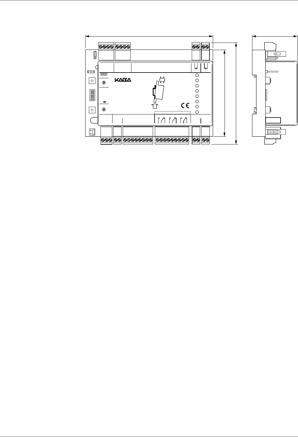
3.6.2 Dimensions
125
84
102
45
0
1
2
3
4
5
6
7
8
9
A
B
C
D
E
F
0
1
2
3
4
5
6
7
8
9
A
B
C
D
E
F
Mode
7
1
8 Service
ON OFF
GND
GND
GND
GND
GND
State
IN1
IN2
IN3
IN4
OUT1
OUT2
OUT3
5V
Rx
Tx
Rx
Tx
0V
IN5/TP
IN1
IN2
IN3
IN4
Vs-
Vs-
Vs+
Vs+
Function
OUT1
OUT2
OUT3
A
B
C
Supply 10-34VDCOutput max. 34VDC/27VAC/2AInput max. 5VDCRS-485
5V
0V
RS-232 B RS-232 A Ant. B Ant. A
AS
A+
AS
A+
:
Address
Prog.
Relay Output Class II
91 25
2.
1. Push
Click
DIN-Rail
91 25
0 - F
0 - F
Product Description Technical Manual
22 04045708 - 04/2016 Kaba Remote Reader 91 25-AM (US/
CAN)
3.7 Conformity
This product conforms to the following standards:
EN 60950-1 : 2014-08
EN 60950-1:2006/A2:2013
UL 60950-1:2007/R:2014-10
CAN/CSA-C22.2 No. 60950-1:2007/A2:2014-10
EN 301 489-1 V1.9.2 : 2011-09
EN 301 489-3 V1.6.1 : 2013-08
EN 300 330-1 V1.8.1 : 2014-12
EN 300 330-2 V1.6.1 : 2014-12
in accordance with the provisions of the EC directives
2014/53/EC: R&TTE Directive
RoHS This device complies with the regulations of the Directive 2011/65/EU of the Euro-
pean Parliament and of the Council of June 8, 2011, on the restriction of the use of
certain hazardous substances in electrical and electronic equipment.
The original Declaration of Conformity can be downloaded from
www.kaba.com/conformity in PDF format.
Tested Standard:
FCC Code of Federal Regulations, CFR 47, Part 15, Sections 15.205, 15.207, 15.215 and
15.225
FCC ID NVI-KRR9125-K5
FCC § 15.19
This device complies with Part 15 of the FCC rules. Operation is subject to the follow-
ing two conditions: (1) This device may not cause harmful interference, and (2) this
device must accept any interference received, including interference that may cause
undesired operation.
FCC § 15.21 (Warning Statement)
[Any] changes or modifications not expressly approved by the party responsible for
compliance could void the user’s authority to operate the equipment.
FCC § 15.105
Note: This equipment has been tested and found to comply with the limits for a Class
A digital device, pursuant to part 15 of the FCC Rules. These limits are designed to
provide reasonable protection against harmful interference when the equipment is
operated in a commercial environment. This equipment generates, uses, and can ra-
diate radio frequency energy and, if not installed and used in accordance with the in-
struction manual, may cause harmful interference to radio communications. Opera-
tion of this equipment in a residential area is likely to cause harmful interference in
which case the user will be required to correct the interference at his own expense.
Tested Standard:
Industry Canada Radio Standards Specifications RSS-GEN Issue 4, Sections 8.8, 8.9
and 8.10 and RSS-210 Issue 8, Section A2.6 (Category I Equipment)
IC:11038A-KRR9125-K5
ICES-003
This Class A digital apparatus complies with Canadian ICES-003. Cet appareil
numérique de la classe A est conforme à la norme NMB-003 du Canada.

Technical Manual Product Description
2304045708 - 04/2016Kaba Remote Reader 91 25-AM (US/
CAN)
Canada RSS-GEN 8.4
This device complies with Industry Canada’s licence-exempt RSSs. Operation is sub-
ject to the following two conditions: (1) This device may not cause interference; and
(2) This device must accept any interference, including interference that may cause
undesired operation of the device.
Le présent appareil est conforme aux CNR d’Industrie Canada applicables aux ap-
pareils radio exempts de licence. L’exploitation est autorisée aux deux conditions
suivantes : 1) l’appareil ne doit pas produire de brouillage; 2) l’utilisateur de l’appareil
doit accepter tout brouillage radioélectrique subi, même si le brouillage est suscepti-
ble d’en compromettre le fonctionnement.

Product Description Technical Manual
24 04045708 - 04/2016 Kaba Remote Reader 91 25-AM (US/
CAN)
3.8 Labeling
The identification plate is located on the side of the device.
The following information can be found on the identification plate:
• Device designation
• Article number
• Serial number
• Function type
• Connection data (power supply)
• CE mark
• WEEE mark as per DIN EN 50419
Technical Manual Design and function
2504045708 - 04/2016Kaba Remote Reader 91 25-AM (US/
CAN)
4 Design and function
4.1 Device structure
0
1
2
3
4
5
6
7
8
9
A
B
C
D
E
F
0
1
2
3
4
5
6
7
8
9
A
B
C
D
E
F
Mode
7
1
8 Service
ON OFF
GND
GND
GND
GND
GND
State
IN1
IN2
IN3
IN4
OUT1
OUT2
OUT3
5V
Rx
Tx
Rx
Tx
0V
IN5/TP
IN1
IN2
IN3
IN4
Vs-
Vs-
Vs+
Vs+
Function
OUT1
OUT2
OUT3
A
B
C
Supply 10-34VDCOutput max. 34VDC/27VAC/2AInput max. 5VDCRS-485
5V
0V
RS-232 B RS-232 A Ant. B Ant. A
AS
A+
AS
A+
:
Address
Prog.
Relay Output Class II
91 25
2.
1. Push
Click
DIN-Rail
91 25
0 - F
0 - F
8 7
5
6
13
14
15
16
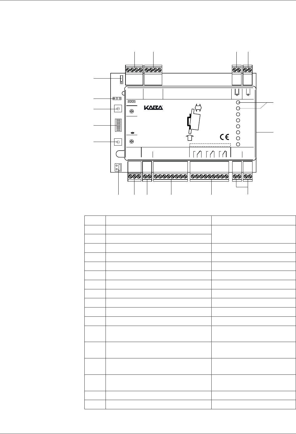
17
1 2 3 4
9101112
Item Connection/switch Remark
1 RS-232 interface B Connection of peripherals
2 RS-232 interface A
3 Antenna B Registration unit B (antenna B)
4 Antenna A Registration unit A (antenna A)
5 LED Displays
6 Interface for Extension Modules e.g. 90 30/90 31
7 Power supply 10–34 VDC
8 Relay outputs OUT1–OUT3
9 Inputs IN1–IN4
10 Tamper switch
11 RS-485 interfaces A, B and C Connection to the host system
12 Bus termination RS-485 Jumper for adjustment of the
termination resistance
13 Addressing RS-485, 1–8 Rotary switch for selecting the
address
14 Function DIP switch for selecting the
function
15 Operating modes 'Mode' rotary switch for select-
ing the operating mode
16 Interface for Kaba programmer PD 1460
17 Not used
Design and function Technical Manual
26 04045708 - 04/2016 Kaba Remote Reader 91 25-AM (US/
CAN)
The functions and connections of the interfaces, inputs, relay outputs, rotary and DIP
switches are described in the chapterDesign and function [}4].
4.2 Firmware
The hardware of this product is used in various Kaba system solutions. The functions
and possible uses of the product are determined by the firmware used.
This manual solely describes the Kaba remote reader 91 25 functional type access
manager (AM).
Firmware designation
Reader type MMIFARE
ALEGIC
BLEGIC or MIFARE
(determined during commissioning)
MRD (multi RFID device)
Device type RC Compactreader
RR Remotereader 91 15
RE Remotereader 91 25
Functional type AE300 V4 or N300/T300/U300 V3
BAccess Manager
CSubterminal
EAMC/II (cDML)
Version number xx.xx Version
Addition 1 RFinal, approved version
Addition 2 ASubversion
Addition 3 _Reserve
Example
Designation of firmware for Kaba remote reader 91 25 with functional type access
manager:
• BREB03.xxRxx (MRD)
Firmware mark on the product
Devices with firmware with the functional type access manager bear a mark reading
"Type: Access manager" on the identification plate.
4.3 System Requirements
• Kabaexos9300 release 4.0.1 and higher
• Kaba access manager 92 00 AM firmware version 3.00 and higher
Further details can be found in the Release Overviews and Release Notes.

Technical Manual Design and function
2704045708 - 04/2016Kaba Remote Reader 91 25-AM (US/
CAN)
4.4 Behavior with two Registration Units
The Remote reader 91 25 communicates alternately via the connections 'Ant. A' and
'Ant. B' (toggling) with the connected registration units. This means that the Remote
reader 91 25 cannot communicate with both registration units at the same time. This
results in the following behavior:
• During a longer reading process, the other registration unit is blocked.
• The fields of the two connected registration units do not influence each other.
This means that the two registration units can be installed close together.
• In the case of registration units installed close together, it may be the case that
the medium is read by the two registration units one after the other.
4.5 Behavior with Several Media in the Field (Anti-Collision)
The Remote reader 91 25 can recognize several LEGIC advant user media (ISO 14443
A) in the field simultaneously. The Remote reader 91 25 only considers the first user
medium, which corresponds to the search criteria defined in the system. The remain-
ing user media are ignored.

Design and function Technical Manual
28 04045708 - 04/2016 Kaba Remote Reader 91 25-AM (US/
CAN)
4.6 Functions
All data for access decisions are saved in the host control device. The authorization
check of a badge and access control are undertaken by the control device.
Functions available before the remote reader is connected to the host system
Standalone access control (without host system); see chapter "Standalone Access
Control without Host System" Commissioning [}6.2]
Access control functions
• Authorization check using badges and temporal authorization incl. verification
• Connection of two separate registration units
• Control of optical and acoustic signal transmitters of the registration units
• Control of electric strikes (doors with electrical blocking elements)
• Support for door opener keys or door handle contacts
• Monitoring of the door status with frame contact, bolt monitoring and door han-
dle contact
• CardLink support: Validation and UID additional recording (only LEGIC)
• Inspection of the functionality even without host system
• Two RS-232 serial interfaces, e.g., for keypads, Hyper X or system-dependent
functions, such as input or issue (only online) of user media numbers
• Hold-open mode, so that, when access is authorized, the door remains open for
as long as the badge remains within range of the antenna (field)
• Monitoring of a tamper switch by integrating the Remotereader into housing
• Signal for authorized access, e.g., for alarm bypass
Restrictions with interrupted connection (offline)
MIFARE
Reduced authorization check using site keys.
Door function is retained depending on the offline parameter setting.
• Authorization check using site keys. A maximum of eight site keys can be saved.
• Not taken into consideration: Time zones and PIN code
• Logbook for 2000 events
• No room monitoring/balancing and no CardLink functionality
• No change in fabrication key
LEGIC
Reduced authorization check using segment search keys. Door function is retained
depending on the offline parameter setting.
• Authorization check using segment search keys. A maximum of eight segment
search keys can be saved.

Technical Manual Design and function
2904045708 - 04/2016Kaba Remote Reader 91 25-AM (US/
CAN)
• Not taken into consideration: Time zones and PIN code
• Logbook for 2000 events
• No room monitoring/balancing and no CardLink functionality
Restored connection
Automatic forwarding of saved bookings as well as status and alarm messages when
connection is restored.

Design and function Technical Manual
30 04045708 - 04/2016 Kaba Remote Reader 91 25-AM (US/
CAN)
4.7 LED Display
The LED display shows operating statuses and errors. Troubleshooting tips are listed
in Chapter [}8].
LED Designation LED Behavior Meaning
State green permanent Device in operation (off-
line)
flashes green RS-485 interface in the re-
ceive or send mode (on-
line)
orange permanent Service mode
red permanent or off Device defective
flashes green and orange After an interruption in
communication, until the
device is queried for the
first time by the host sys-
tem
IN1–IN4 green permanent LED lights once the corre-
sponding input is enabled
orange flashing Service mode
orange permanent or off Update via programmer
1460
IN1–IN4
Monitoring enabled
orange permanent Short circuit
red permanent interruption
OUT1–OUT3 green permanent the relevant output is ac-
tive
flashes green Undervoltage (Vs) or relay
defective
red permanent Write/read authorization
(launch data) is deleted
OUT1 red permanent Input 5 (only in Kaba exos
lock operating mode)
As soon as the door han-
dle contact is active

Technical Manual Design and function
3104045708 - 04/2016Kaba Remote Reader 91 25-AM (US/
CAN)
4.8 Operating Types
4.8.1 Overview of Operating Types
An operating type of the Remotereader is always made up of the operating mode
(door configuration) with the associated extended functions and of the communica-
tion with the host system (access hub). The Remotereader supports the online and
offline operating types.
Online operation: The Remotereader communicates with the system.
Offline operation: If a Remotereader connected with the system is discon-
nected from the system, then the Remotereader switches
to the offline mode.
For the online and offline operation of the device, a minimum of the following hard-
ware settings must be carried out before putting into operation:
System used Minimum hardware settings
Kabaexos9300 Online operation:
• Address
Offline operation:
• DIP and rotary switch

Design and function Technical Manual
32 04045708 - 04/2016 Kaba Remote Reader 91 25-AM (US/
CAN)
4.8.2 Online operation
In online operation, the Remotereader communicates with the host system. The sys-
tem makes the access decision on the basis of badges, time-dependent authorization
and verification. The system controls the access points. If communication between
Remotereader and system is interrupted, then the Remotereader independently
switches into offline operation. If the Remotereader is queried by the system again,
then the Remotereader switches back into online operation.
4.8.3 Offline Operation
Even in offline operation, i.e. without communication with the host system, an access
point is monitored and controlled by the Remotereader. For access decisions,
site keys are used under MIFARE and
segment search keys are used under LEGIC.
The Remotereader controls access points in accordance with the operating mode,
door configuration and the corresponding 'extended functions' (offline configura-
tion).
In order to ensure fault-free offline operation, the Remotereader should be operated
with a secure power supply (e.g. UPS).
Offline operation can be turned off in the system and/or using the 'Mode' rotary
switch (F = off). This means that the offline behavior defined in the hardware settings
is deactivated and the access point remains blocked if there is an interruption in
communication.
Behavior in the event of an interruption to communication
• The access point goes to the basic status (possibly alarm if the access point is not
closed)
• Relays which are not involved in a door process (according to DIP switch) deacti-
vate; the same is true for the connected Kaba extension module 9030.
4.8.3.1 Offline Access Decision
The customer determines the nature of the offline access decision which is parame-
terized in the system. We differentiate the following offline access decisions:
Parameter settings in the system: no offline access decision
The Remotereader rejects all bookings in offline operation.
Parameter settings in the system:
Checking site key (MIFARE)/segment search key (LEGIC)
In the online mode, the site key (MIFARE)/segment search key (LEGIC) is sent to the
Remotereader by the system and saved in the Remotereader. During the offline
mode, the Remotereader only checks the site key (MIFARE)/segment search key
(LEGIC). The time zone is not considered for this kind of access decision.
Logbook
The logbook records and saves a maximum of 2000 events during the offline opera-
tion. Once the Remotereader is online again, the saved data is sent to the host sys-
tem and deleted from the memory of the Remotereader.
The following events are logged:
• Authorized accesses (incl. type of authorization)
• Tampering, door forced open, door opener key
If there are more than 2000 entries, the oldest will be overwritten (ring memory).
Service mode
See chapter Service mode [}7.3]


Design and function Technical Manual
34 04045708 - 04/2016 Kaba Remote Reader 91 25-AM (US/
CAN)
4.9 Operating modes
The operating mode of the Remotereader must be selected on the basis of the door
configuration.
The operating mode is set using the rotary switch, see Chapter Set Operating Mode.
The extended functions of a selected operating mode are set using the DIP switch
Extended functions of the operating modes [}5.7.6.1].
Possible operating modes:
• Electric strike; for doors with electrical blocking elements
• Motor bolt; for doors with electrical blocking elements
• Automatic doors; for doors with their own electronic control system (control with
enable pulse; e.g. sliding door)
• Turnstile; for turnstiles/tripod turnstiles with their own electronic control system
(control with direction-dependent enable pulses)
• Night lock; for doors with the two elements electronic strike and motor bolt
• Kaba exos lock; for doors with self-locking Kaba panic locks;
• Cylinder interface LI-EL; for doors with mechatronic Kaba elolegic cylinders
• Motor bolt with panic function; for doors with electrical blocking elements and
additional mechanical panic opening
• Motor bolt type II with panic function (two outputs); for doors with electrical
blocking elements and additional mechanical panic opening. 1 output each for
the pulses 'unlock' and 'lock'.
• Motor bolt type III with panic function (1 output); for doors with electrical block-
ing elements and additional mechanical panic opening. 1 output for the pulses
'unlock' and 'lock'.
• Electric lock with panic function; for doors with electrical blocking elements and
additional mechanical panic opening
• Automatic door with night lock for doors with their own electronic control sys-
tem and additional night lock
Also see about this
24.9.1'Electric strike' operating mode [}35]
Technical Manual Design and function
3504045708 - 04/2016Kaba Remote Reader 91 25-AM (US/
CAN)
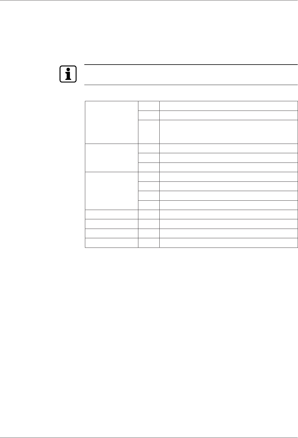
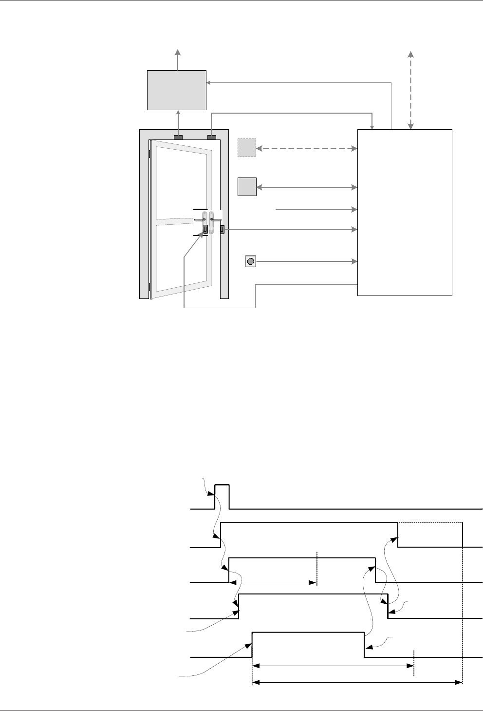
4.9.1 'Electric strike' operating mode
Access allowed
Intrusion
detection
system Frame contact
Electric strike
(Alarm bypass)
(Access control)
Registration unit A
Blocking contact
Registration unit B
Alarm RS-232 A/B
Buzzer / LED
Door opener key
Access manager /
Door manager
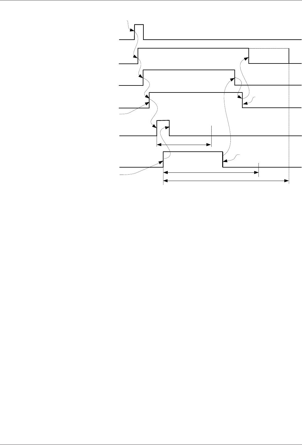
The 'Electric strike' operating mode is mainly used to operate doors with electric lock-
ing elements (strike, magnet).
The access authorised signal is triggered by authorised booking, the door opener key
or the door handle. So that subsequent door opening does not trigger an alarm, the
'Access authorised' signal activates the alarm bypass.
Then the electric strike is triggered. The door is now released for opening and the set
relay operating time starts to run. When the door is opened the pre-alarm and alarm
time start to run ('Door open too long').
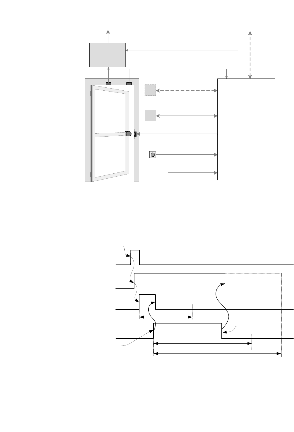
Authorised booking,
door opener key or
door handle trigger
a door opening
Frame contact
Access allowed
Pre-alarm time
Alarm time
Access control
Door open
Access control
Door closed
Electric strike (not used
with a door handle)
Relais operation time
Design and function Technical Manual
36 04045708 - 04/2016 Kaba Remote Reader 91 25-AM (US/
CAN)
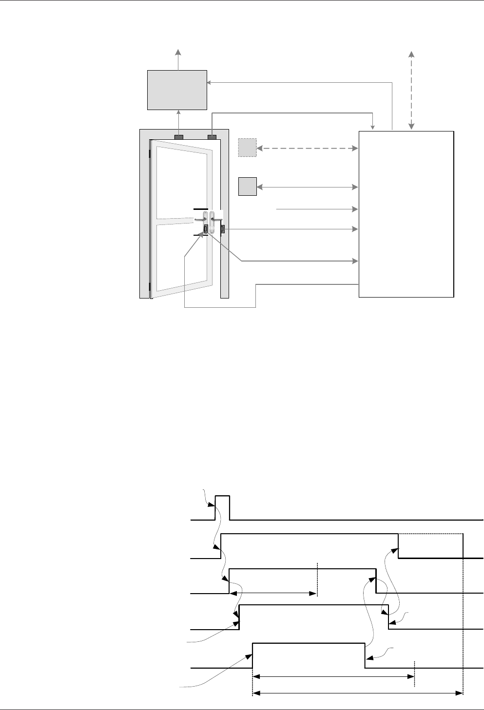
4.9.2 'Motor Bolt' Operating Mode
(locked)
RS-232 A/B
Buzzer / LED
Motor bolt
Bolt monitoring
Access allowed
Frame contact
(Alarm bypass)
(Access control)
Registration unit A
Blocking contact
Registration unit B
Door opener key
Intrusion
detection
system
Alarm
Access manager /
Door manager
The 'motor bolt' operating mode mainly operates doors with electrical locking ele-
ments.
The 'authorized access' signal is generated through being triggered by an authorized
booking or the door opener key. So that subsequent door opening does not gener-
ate an alarm, the 'authorized access' signal activates the alarm bypass.
Then the motor bolt is activated. The door is now released for opening and the set re-
lay operation time starts to run. When opening the door, the pre-alarm and alarm
time start to run ('Door open too long').
The motor bolt is activated until the frame contact signals that the door is closed
again. Only then will the lock of the motor bolt be extended again. If the motor bolt
is not extended (e.g. in the event of a defect or tampering), then an alarm ('Bolt posi-
tion incorrect') is triggered.
Authorised booking
or door opener key
trigger a door
opening
Frame contact
Access allowed
Pre-alarm time
Alarm time
Access control
Door open
Access control
Door closed
Motor bolt
Bold monitoring
Relay operation time
Access control
Door unlocked
Access control
Door locked
Technical Manual Design and function
3704045708 - 04/2016Kaba Remote Reader 91 25-AM (US/
CAN)
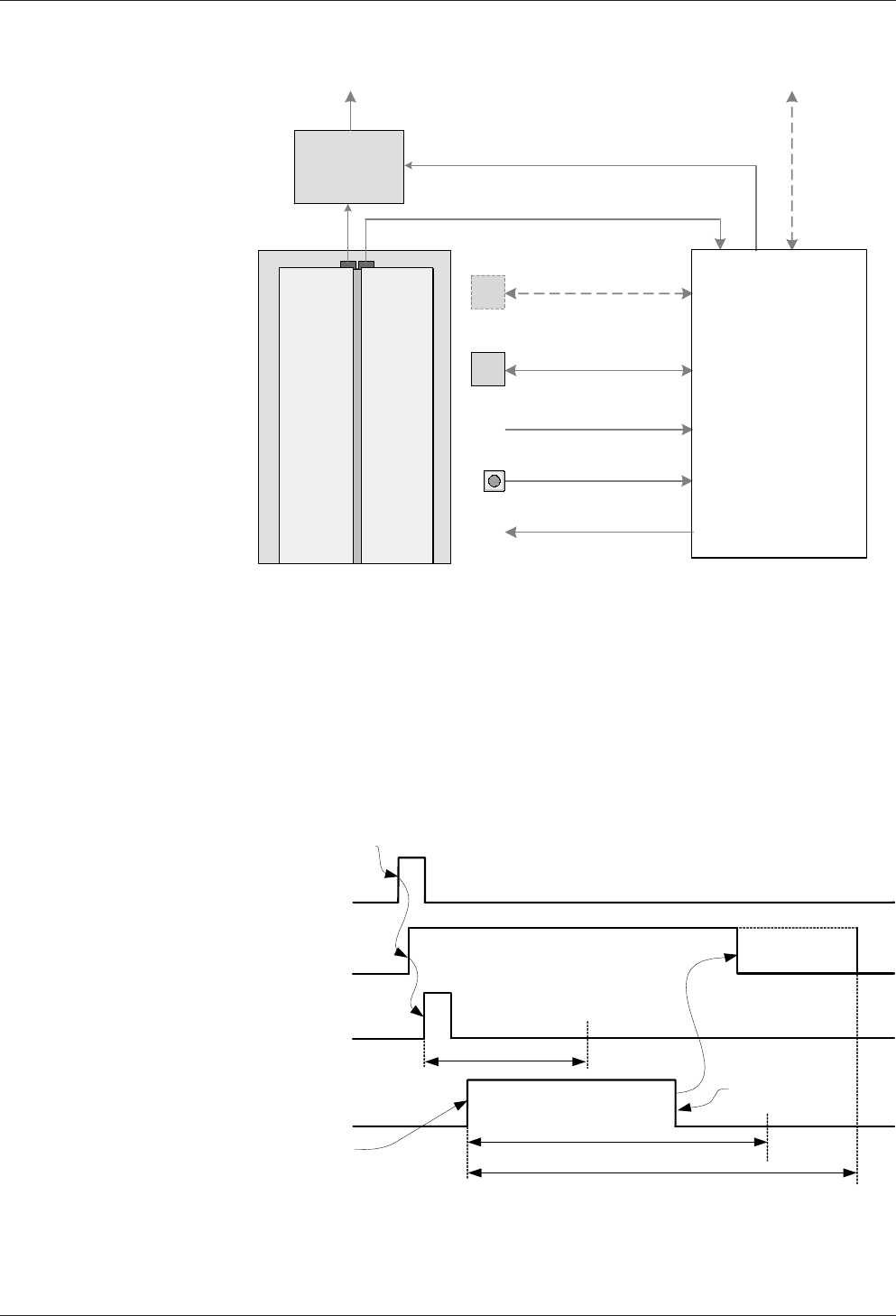
4.9.3 'Automatic door' operating mode
Release pulse
RS-232 A/B
Buzzer / LED
Access allowed
Intrusion
detection
system
Frame contact
(Alarm bypass)
(Access control)
Registration unit A
Blocking contact
Registration unit B
Alarm
Door opener key
Access manager /
Door manager
The 'Automatic doors' operating mode is mainly used to operate doors with their
own control electronics (e.g. sliding doors). The control is carried out using a release
pulse.
The 'Access authorised' signal is generated triggered by an authorised booking or the
door opener key. So that subsequent door opening does not trigger an alarm, the
'Access authorised' signal activates the alarm bypass.
The release pulse (approx. 1s) is then sent to the control electronics. The set relay op-
eration time starts to run. If the door is opened within the relay operation time, then
the pre-alarm and alarm time start to run ('Door open too long').
If the door is opened outside of the relay operation time, then unauthorised door
opening is present.
Authorised booking,
door opener key or
door handle trigger
a door opening
Frame contact
Access allowed
Pre-alarm time
Alarm time
Access control
Door open
Access control
Door closed
Release pulse (not used
with a door handle)
Relais operation time
1s
Design and function Technical Manual
38 04045708 - 04/2016 Kaba Remote Reader 91 25-AM (US/
CAN)
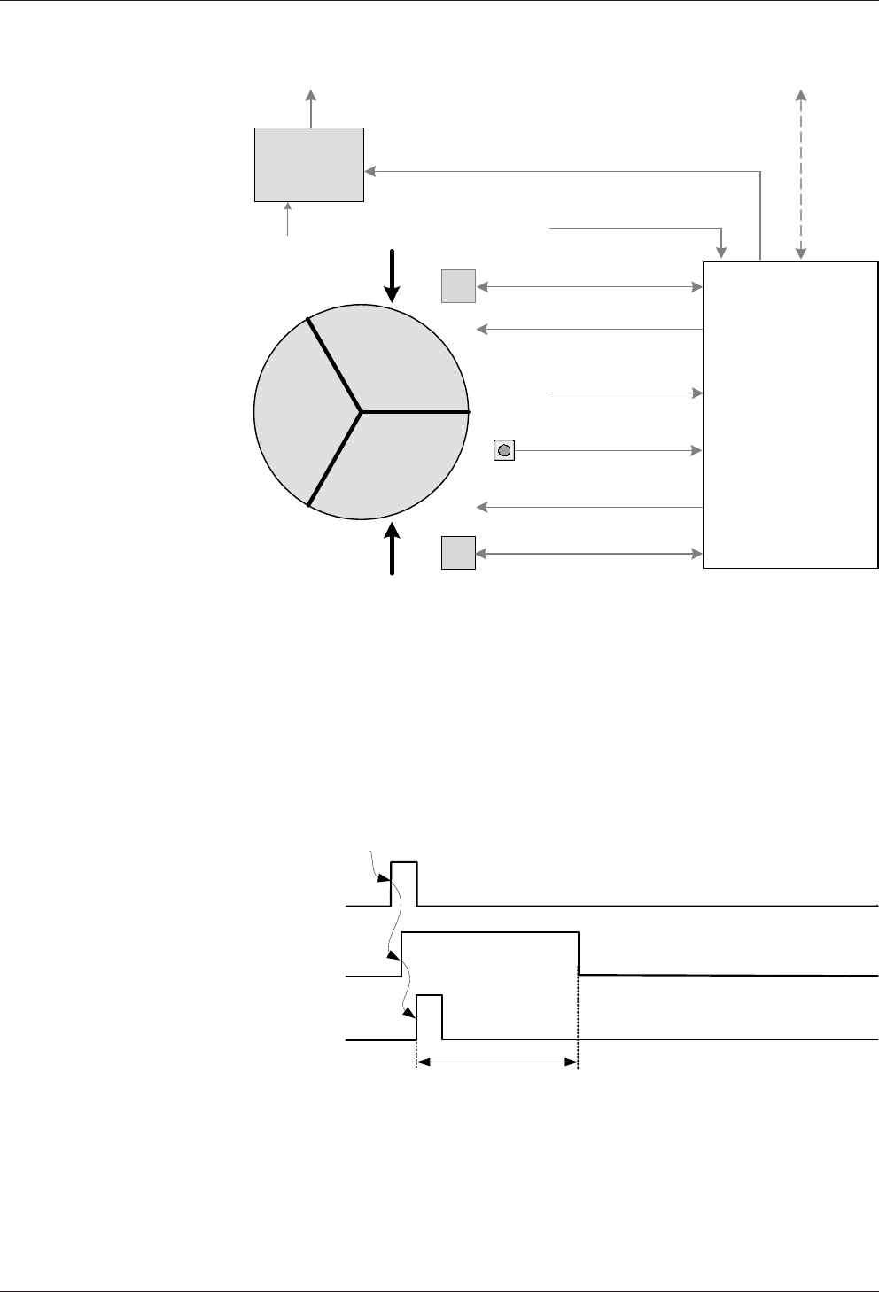
4.9.4 'Turnstile' operating mode
Release pulse
RS-232 A/B
Buzzer / LED
Buzzer / LED
Release pulse
Outside
Inside
Frame contact
(direction-dependent)
(direction-dependent)
Access allowed
Intrusion
detection
system
Frame contact
(Alarm bypass)
(Access control)
Registration unit A
Blocking contact
Registration unit B
Alarm
Door opener key
Access manager /
Door manager
The 'Turnstile' operating mode is mainly used to operate turnstiles/tripod barriers
with their own control electronics (triggered with direction-dependent release
pulses). The turnstile is an access point in which the access point sides (outside/in-
side) are released in a direction-dependent manner. Therefore two opposite direc-
tions of rotation are possible.
The 'access authorised' signal is triggered by authorised booking or the door opener
key. So that subsequent door opening does not trigger an alarm, the 'Access autho-
rised' signal activates the alarm bypass.
Then the direction-dependent release pulse (approx. 1s) is sent to the control elec-
tronics and the set relay operation time starts to run. If the door is opened outside of
the relay operation time, then unauthorised door opening is present.
Authorised booking,
door opener key
trigger a door
opening
Access allowed
Direction-dependent
release puls
Relais operation time
1s
Technical Manual Design and function
3904045708 - 04/2016Kaba Remote Reader 91 25-AM (US/
CAN)
4.9.5 'Night lock' operating mode
RS-232 A/B
Buzzer / LED
Motor bolt
Access allowed
Frame contact
(Alarm bypass)
(Access control)
Registration unit A
Blocking contact
Registration unit B
Door opener key
Intrusion
detection
system
Alarm
Bolt monitoring
(locked)
Electric strike
Access manager /
Door manager
The 'Night lock' operating mode is mainly used to operate doors with the two ele-
ments electric strike and motor bolt. Therefore during the day only the door opener
relay needs to be enabled, and the door can be additionally locked at night (e.g. X-
Lock motor lock with control unit; but without bolt monitoring).
The 'access authorised' signal is triggered by authorised booking or the door opener
key. So that subsequent door opening does not trigger an alarm, the Access autho-
rised signal activates the alarm bypass.
Then the motor bolt is triggered. As soon as the motor bolt is retracted (motor bolt
monitoring), the electric strike is triggered and the door is released for opening. The
set relay operation time starts to run. When the door is opened the pre-alarm and
alarm time start to run ('Door open too long').
• The time profile saved for the night lock only works in online mode.
• Offline mode always corresponds to the night setting. Motor bolt and door
opener relay are controlled.
Design and function Technical Manual
40 04045708 - 04/2016 Kaba Remote Reader 91 25-AM (US/
CAN)
Authorised booking,
door opener key or
door handle trigger
a door opening
Frame contact
Access allowed
Pre-alarm time
Alarm time
Access control
Door open
Access control
Door closed
Motor bolt (not used
with a door handle)
Bolt monitoring (not used
with a door handle)
Relais operation time
Electric strike (not used
with a door handle)
Access control
Door unlocked
Access control
Door locked
Technical Manual Design and function
4104045708 - 04/2016Kaba Remote Reader 91 25-AM (US/
CAN)
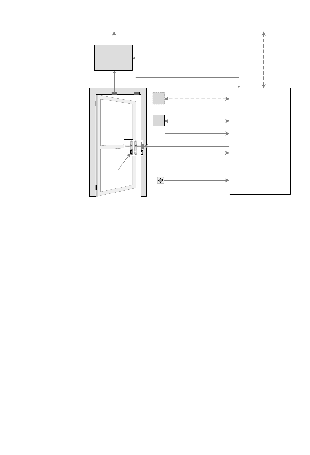
4.9.6 'Motor bolt with panic function' operating mode
(locked)
RS-232 A/B
Buzzer / LED
Motor bolt
Bolt monitoring
Access allowed
Frame contact
(Alarm bypass)
(Access control)
Registration unit A
Blocking contact
Registration unit B
Door handle contact
Intrusion
detection
system
Alarm
Access manager /
Door manager
The 'Motor bolt with panic function' operating mode is implemented in the same
way as the 'Motor bolt' operating mode. Instead of the door opener key, the door
handle contact is assessed for mechanical panic opening.
The 'access authorised' signal is triggered by an authorised booking or the door han-
dle. So that subsequent door opening does not trigger an alarm, the 'Access autho-
rised' signal activates the alarm bypass.
The door is now released for opening and the set relay operating time starts to run.
When the door is opened the pre-alarm and alarm time start to run ('Door open too
long').
The motor bolt is controlled until the frame contact signals that the door is closed
again. Only then will the bolt of the motor lock be extended again. If the motor bolt
is not extended (e.g. in the event of a defect or tampering), then an alarm ('Bolt posi-
tion incorrect') is triggered.
Authorised booking
or door handle
trigger a door
opening
Frame contact
Access allowed
Pre-alarm time
Alarm time
Access control
Door open
Access control
Door closed
Motor bolt (not used
with a door handle)
Bolt monitoring (not used
with a door handle)
Relay operation time
Access control
Door unlocked
Access control
Door locked

Design and function Technical Manual
42 04045708 - 04/2016 Kaba Remote Reader 91 25-AM (US/
CAN)
4.9.7 'Motor bolt type II with panic function' operating mode (2 outputs)
(locked)
RS-232 A/B
Buzzer / LED
Lock motor bolt
Bolt monitoring
Access allowed
Frame contact
(Alarm bypass)
(Access control)
Registration unit A
Blocking contact
Registration unit B
Door handle contact
Intrusion
detection
system
Alarm
Unlock motor bolt
Access manager /
Door manager
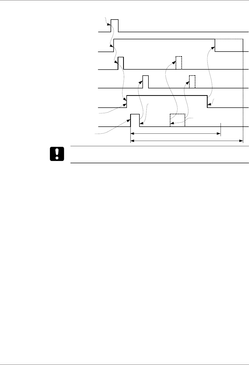
The 'Motor bolt type II' operating mode is implemented in the same way as the 'Mo-
tor bolt with panic function' operating mode. In place of the static 'Motor bolt' signal,
there is one line each for 'Motor bolt unlocking' and 'Motor bolt locking' connected
to the lock (e.g. MIWA AL-02/AL-3M).
The 'access authorised' signal is triggered by an authorised booking or the door han-
dle. So that subsequent door opening does not trigger an alarm, the 'Access autho-
rised' signal activates the alarm bypass.
Then the motor bolt is retracted with the 'unlock' pulse. The door is now released for
opening. When the door is opened the pre-alarm and alarm time start to run ('Door
open too long').
If the frame contact signals that the door is closed again, then the bolt of the motor
lock is extended again via the 'lock' pulse. If the motor bolt is not extended (e.g. in
the event of a defect or tampering), then an alarm ('Bolt position incorrect') is trig-
gered. If the unlocked door (bolt monitoring) is opened again, no alarm will be gen-
erated.
Technical Manual Design and function
4304045708 - 04/2016Kaba Remote Reader 91 25-AM (US/
CAN)
No alarm!
Unlock motor bolt (not
used with a door handle)
Lock motor bolt (not used
with a door handle)
Authorised booking
or door handle
trigger a door
opening
Frame contact
Access allowed
Access control
Door open
Access control
Door unlocked
Bolt monitoring (not used
with a door handle) Access control
Door closed
Access control
Door locked
Pre-alarm time
Alarm time
Depending on the door used, it may be the case that a door opener key is parame-
terised as the door component in Kabaexos instead of a door handle.

Design and function Technical Manual
44 04045708 - 04/2016 Kaba Remote Reader 91 25-AM (US/
CAN)
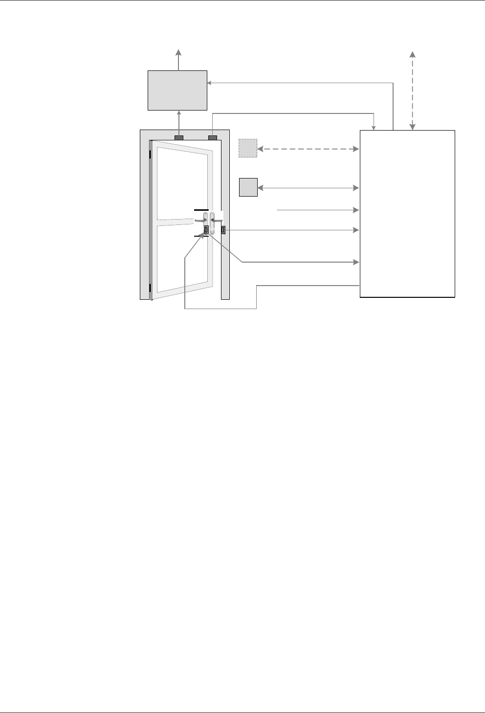
4.9.8 'Motor bolt type III with panic function' operating mode (1 output)
(locked)
RS-232 A/B
Buzzer / LED
Lock motor bolt
Bolt monitoring
Access allowed
Frame contact
(Alarm bypass)
(Access control)
Registration unit A
Blocking contact
Registration unit B
Door handle contact
Intrusion
detection
system
Alarm
Unlock motor bolt
Access manager /
Door manager
The 'Motor bolt type III' operating mode is implemented in the same way as the 'Mo-
tor bolt with panic function' operating mode. Instead of the static 'Motor bolt' sig-
nals, the 'Motor bolt unlocking' pulse is generated on one output and the 'Motor bolt
locking' pulse is generated on the other output.
The 'access authorised' signal is triggered by an authorised booking or the door han-
dle. So that subsequent door opening does not trigger an alarm, the 'Access autho-
rised' signal activates the alarm bypass.
Then the motor bolt is retracted with the 'unlock' pulse. Now the door is released for
opening. When the door is opened the pre-alarm and alarm time start to run ('Door
open too long').
If the frame contact signals that the door is closed again, then the bolt of the motor
lock is extended again via the 'lock' pulse. If the motor bolt is not extended (e.g. in
the event of a defect or tampering), then an alarm ('Bolt position incorrect') is trig-
gered.
Unlock motor bolt
Lock motor bolt
(not used with a door handle)
Authorised booking or
door handle trigger a
door opening
Frame contact
Access allowed
Pre-alarm time
Alarm time
Access control
Door open
Access control
Door closed
Access control
Door unlocked
Access control
Door locked
Bolt monitoring (not used
with a door handle)

Technical Manual Design and function
4504045708 - 04/2016Kaba Remote Reader 91 25-AM (US/
CAN)
Depending on the door used, it may be the case that a door opener key is parame-
terised as the door component in Kabaexos instead of a door handle.
Design and function Technical Manual
46 04045708 - 04/2016 Kaba Remote Reader 91 25-AM (US/
CAN)
4.9.9 'Electric lock with panic function' operating mode
(locked)
RS-232 A/B
Buzzer / LED
Electric lock
Bolt monitoring
Access allowed
Frame contact
(Alarm bypass)
(Access control)
Registration unit A
Blocking contact
Registration unit B
Door handle contact
Intrusion
detection
system
Alarm
Access manager /
Door manager
The 'Electric lock with panic function' operating mode is implemented in the same
way as the 'Motor bolt with panic function' operating mode. An electric lock (e.g. X-
Lock electric lock, MIWA AUTA/ALTA) is controlled instead of the motor bolt.
The 'access authorised' signal is triggered by an authorised booking or the door han-
dle. So that subsequent door opening does not trigger an alarm, the 'Access autho-
rised' signal activates the alarm bypass.
Then the electric lock is triggered. The door is now released for opening and the set
relay operating time starts to run. When the door is opened the pre-alarm and alarm
time start to run ('Door open too long').
The 'Access authorised' signal is enabled during the alarm time until the door is
locked.
If the door is opened again during this alarm time, then no alarm is generated.
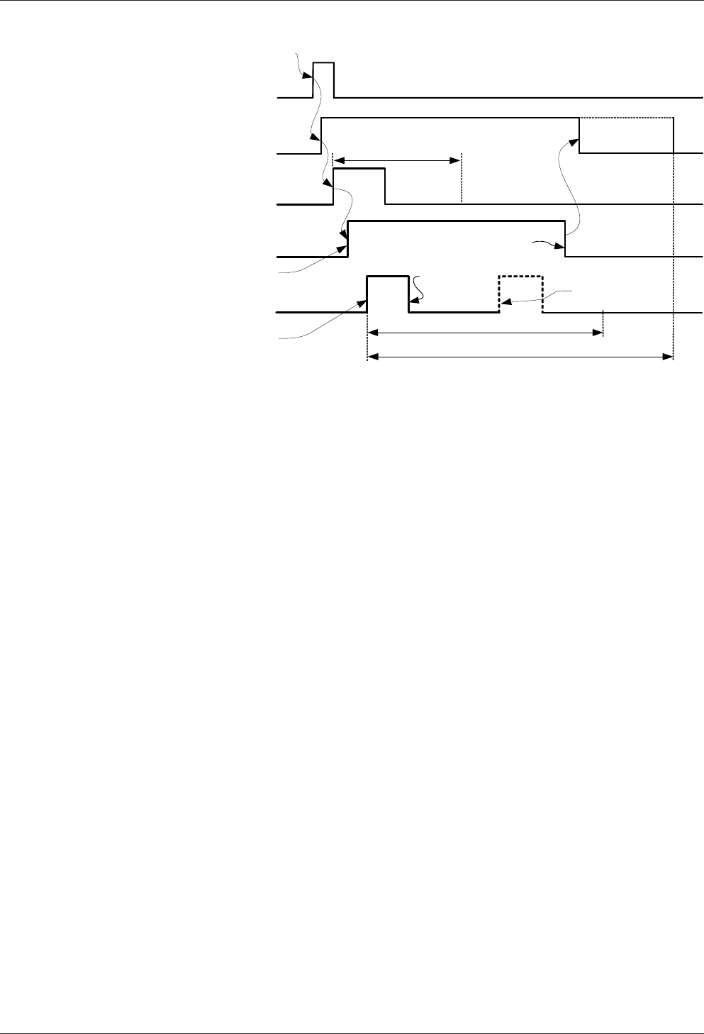
Technical Manual Design and function
4704045708 - 04/2016Kaba Remote Reader 91 25-AM (US/
CAN)
Frame contact
Access allowed
Pre-alarm time
Alarm time
Access control
Door open
No alarm!
Electric lock (not used
with a door handle)
Deadbolt contact
Relay operation time
Access control
Door unlocked
Access control
Door locked
Access control
Door closed
Authorised booking
or door handle
trigger a door
opening
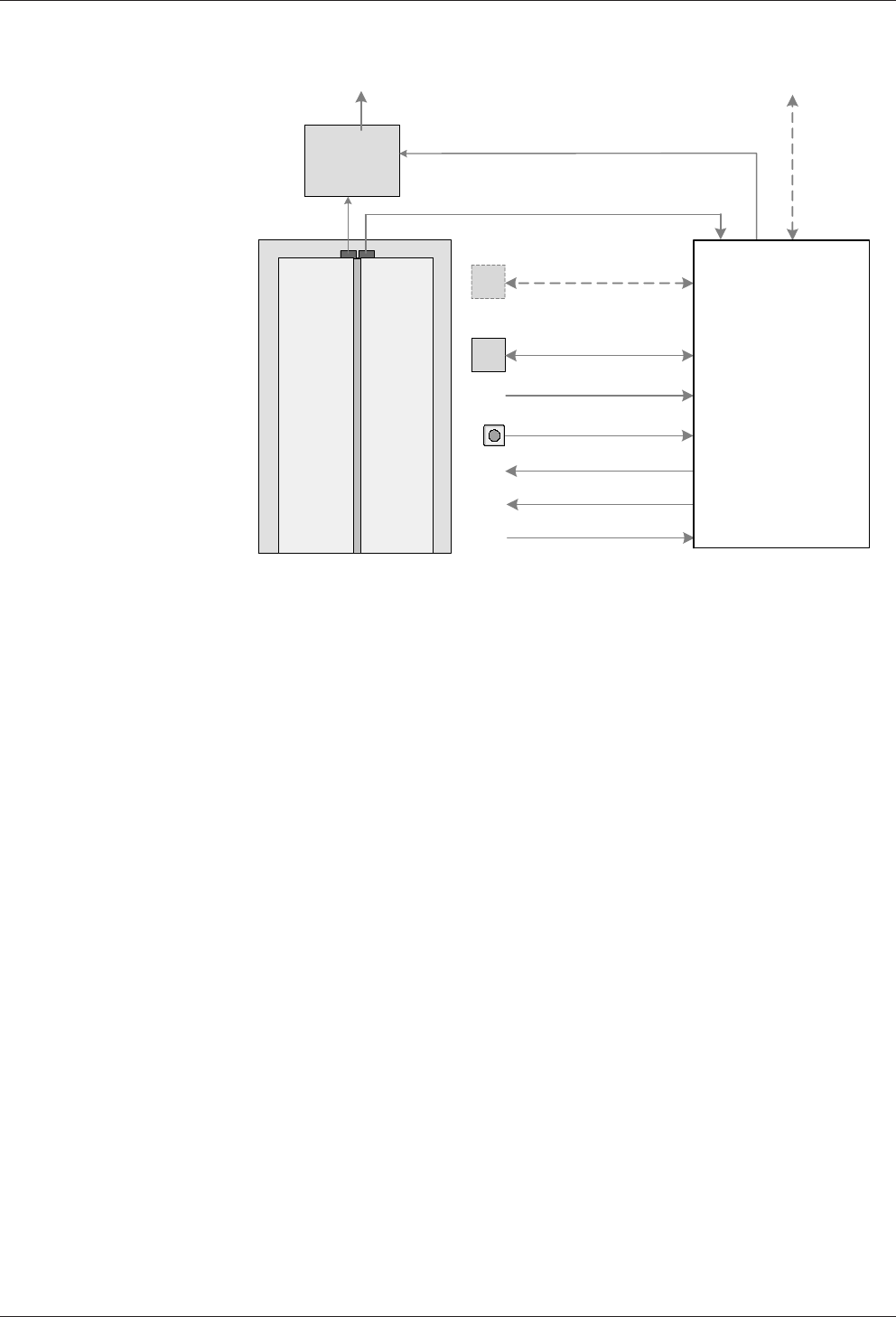
Design and function Technical Manual
48 04045708 - 04/2016 Kaba Remote Reader 91 25-AM (US/
CAN)
4.9.10 'Automatic door with night lock' operating mode
Release pulse
Alarm RS-232 A/B
Intrusion
detection
system
Access allowed
(Alarm bypass)
Frame contact
(Access control)
Registration unit B
Buzzer / LED
Registration unit A
Blocking contact
Motor bolt
Door opener key
Bolt monitoring
Access manager /
Door manager
The 'Automatic door with night lock' mode is used to operate automatic doors with
the two elements release pulse and motor bolt. This means that during the day only
the release pulse is active and at night the door is additionally locked.
The 'access authorised' signal is triggered by authorised booking or the door opener
key. So that subsequent door opening does not trigger an alarm, the 'Access autho-
rised' signal activates the alarm bypass.
Then the motor bolt is triggered. As soon as the bolt is retracted (bolt monitoring),
the release pulse (approx. 1s) is sent to the control electronics. The set relay opera-
tion time starts to run. If the door is opened within the relay operation time, then the
pre-alarm and alarm time start to run ('Door open too long').
If the door is opened outside of the relay operation time, then unauthorised door
opening is present.
• The time profile saved for the night lock only works in online mode.
• Offline mode always corresponds to the night setting. Motor bolt and door
opener relay are controlled.
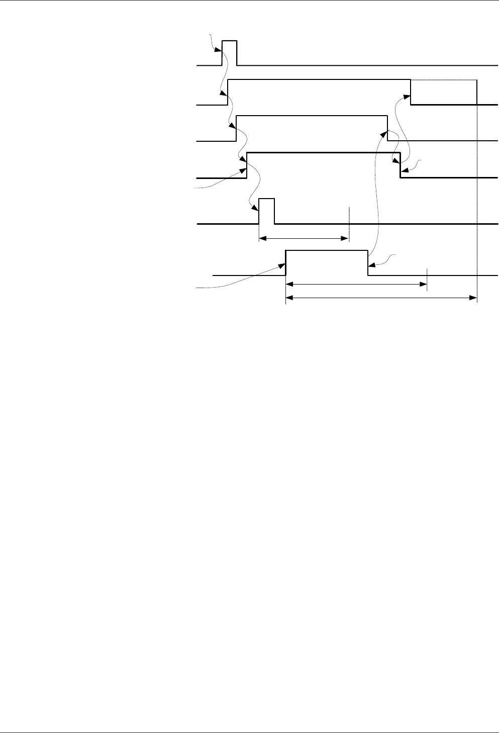
Technical Manual Design and function
4904045708 - 04/2016Kaba Remote Reader 91 25-AM (US/
CAN)
1s
Authorised booking
or door handle
trigger a door
opening
Frame contact
Access allowed
Access control
Door open
Motor bolt (not used
with a door handle)
Bolt monitoring (not used
with a door handle)
Access control
Door unlocked
Release pulse (not used
with a door handle)
Pre-alarm time
Alarm time
Access control
Door closed
Relay operation time
Access control
Door locked
4.9.11 'Online Operation' Operating Mode
The 'Online operation' operating mode is used for purely online operation. If commu-
nication to the host system is interrupted, then no locking elements will be activated.
All connected outputs and relays drop off.

Installation Technical Manual
50 04045708 - 04/2016 Kaba Remote Reader 91 25-AM (US/
CAN)
5 Installation
This chapter describes the installation of the device.
5.1 Installation process
Procedure
1. Determine the installation site.
Installation site [}5.2.2]
2. Lay the installation cables.
Installation lines [}5.4]
3. Secure the device.
4. Connect registration units.
'Ant. A' and 'Ant. B' Connections [}5.6.4],
Coaxial Cable to the Registration Units [}5.4.4],
Coaxial Cable Terminal [}5.4.6.4]
5. Check read behavior without system configuration:
Book with an ISO 14443 A medium or Legic Prime medium.
ðIf the medium can be read, the registration unit signals this as unauthorized
access.
6. Connect keypads or system-dependent functions.
RS-232 A and RS-232 B Interfaces
7. Connect the inputs.
Inputs IN1 – IN4, tamper and input 5 [}5.6.8]
8. Connect the relay outputs.
Output OUT1 – OUT3 [}5.6.9]
9. Plug in/connect extension modules where required.
10. Connect Kaba remote reader 91 25 and host device to the RS-485 bus cable.
RS-485 interface [}5.6.3]
Configure the device after installation.
Configuring [}5.7]
Also see about this
25.5Mounting the device and extension modules [}60]
25.4Installation lines [}53]
25.7Configuring [}68]

Technical Manual Installation
5104045708 - 04/2016Kaba Remote Reader 91 25-AM (US/
CAN)
5.2 Installation conditions
5.2.1 General
An accurate installation of all components is a basic requirement for a properly func-
tioning device. The following installation instructions must be adhered to.
5.2.2 Installation site
The device is assembled on a DIN rail in a housing or IT cabinet.
The device should be installed in a tamper-proof location within the area to be se-
cured.
Electromagnetic fields
The device must not be installed in the area of strong electromagnetic fields caused
by switching power supply, power lines, phase controllers, etc.!
5.2.3 Connections
The following connections must be available at the location where the access man-
ager is to be installed:
• Power supply for the device
• RS-485 cable to the host device
• Cables to door openers and switches
• Coaxial cable to registration units
The installation lines have to be flush with the surface or be laid in the vandal-proof
area.
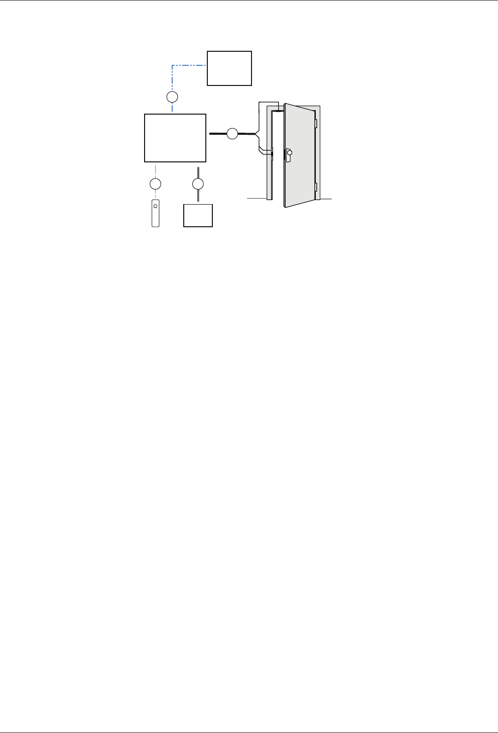
Installation Technical Manual
52 04045708 - 04/2016 Kaba Remote Reader 91 25-AM (US/
CAN)
5.3 Installation layout (example)
91 25
4
B
56
3
1
2
C
A
D
DC
1 Kaba remote reader 91 25
2 Kaba access manager 92 00
3 Door frame contact
4 Door contact, door opener
5 Power supply
6 Kaba registration unit
Installation cables
A Data line
B Power supply line
C Line to the door opener and door contacts (if required)
D Coaxial cable
Technical Manual Installation
5304045708 - 04/2016Kaba Remote Reader 91 25-AM (US/
CAN)
5.4 Installation lines
This chapter describes:
• Line requirements
• Maximum permitted line length
• Grounding concept
The chapter Connections describes the assignment of connections and switch set-
tings.
Only connect the terminals when the power is switched off.
5.4.1 Power supply line
The device can be supplied with power in the following ways:
• From the host control device (power supply and data line in one cable)
• From a separate power supply
NOTICE
Voltage drops, caused by line resistance, must be taken into consideration for
long lines.
The given cable types and diameters are examples and serve as recommendations.
The technical specifications of the cable manufacturer are authoritative for the pre-
cise determination of the cable diameter/cross section and the resulting maximum
cable lengths. The voltage drop across the cable length is decisive in this case. As
such, the voltage that is available at the end of the cable may, under no circum-
stances, be less than the minimum permitted supply voltage of the connected com-
ponents. This always applies in consideration of the maximum power consumption
of the connected components.
Only connect the terminals when the power is switched off.
The device may only be supplied with SELV (Safety Extra Low Voltage) and LPS (Lim-
ited Power Source), according to IEC/UL/CSA 60950-1.
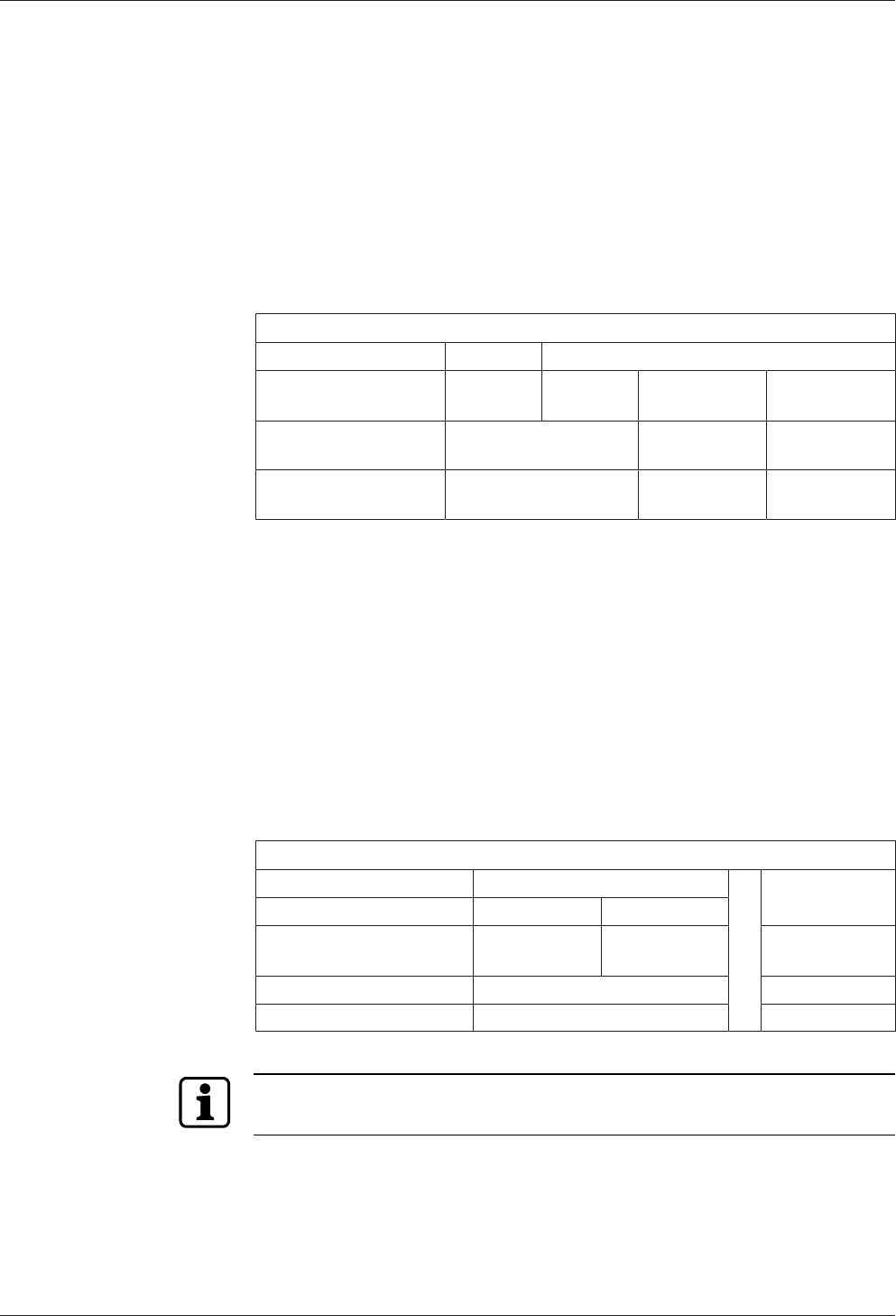
Installation Technical Manual
54 04045708 - 04/2016 Kaba Remote Reader 91 25-AM (US/
CAN)
5.4.1.1 Power supply from the host control device
(Central power supply)
Power is supplied from the host control device.
In the case of bus wiring, the power supply and data line can be carried in one cable
(maximum total length of 350m).
In the case of star wiring, the power supply and data line can be carried in one cable
(maximum length per stub of 20m).
A separate power supply must be used for greater distances.
Permissible Cable Lengths and Cable Types
Type of wiring: Star Bus
Max. cable length: < 20m
(per stub)
< 50m
(total)
< 100m
(total)
< 350m
(total)
Cable type CAT.5 S-UTP
*
4 x 2 x AWG 24 4 x 2 x AWG 22 4 x 2 x AWG 20
Cable type J-Y (ST) 4 x 2 x ø 0.6mm 4 x 2 x ø
0.8mm
4 x 2 x ø
1.0mm
*S-UTP (screened unshielded twisted pair)
Do not ground the device.
5.4.1.2 Power supply and data transfer in separate cables
(Local power supply)
Data lines and power supply lines are carried with one of each in a cable.
Power is supplied locally, e.g. from a power supply unit.
A local power supply can be used in the following cases:
• in long data lines
• if there are increased requirements regarding the operational safety of the de-
vice (offline capability).
Permissible Cable Lengths and Cable Types
Data line RS-485 Power supply
Type of wiring: Star Bus
Max. cable length: < 100m
(per stub)
< 1200m
(total)
< 10m
Cable type CAT.5 S-UTP * 2 x 2 x AWG 24 1 x 2 x AWG 24
Cable type J-Y (ST) 2 x 2 x ø 0.6mm 1 x 2 x ø 0.6mm
*S-UTP (screened unshielded twisted pair)
The device may only be supplied with SELV (Safety Extra Low Voltage) and LPS (Lim-
ited Power Source), according to IEC/UL/CSA 60950-1.
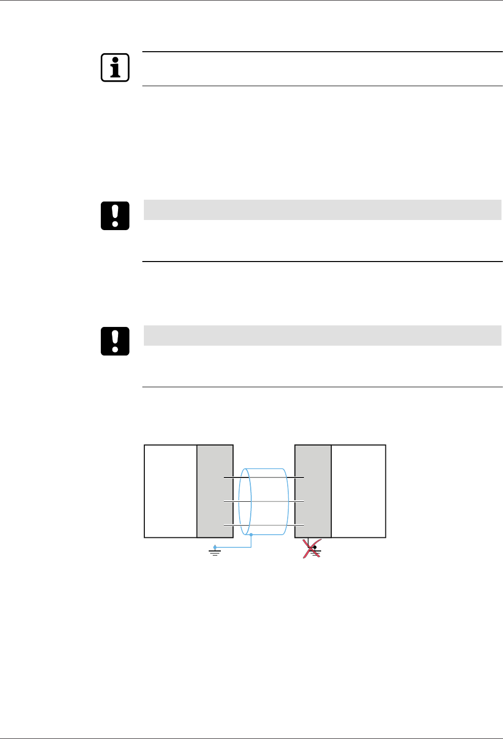
Technical Manual Installation
5504045708 - 04/2016Kaba Remote Reader 91 25-AM (US/
CAN)
5.4.2 Data line RS-485
Only connect the terminals when the power is switched off.
The device is connected to the host control device via a two-wire party line connec-
tion (RS-485).
For information on permissible cable lengths and cable types, please see:
•
•
5.4.2.1 Cable
NOTICE
Local legal provisions (e.g., VDE) must be observed during installation of compo-
nents.
For notes on structured cabling, see the standard EN 50173.
The cables recommended in the chapter have a foil screen and are designed based
on S-UTP (screened unshielded twisted pair). The wire pairs are not individually
shielded against each other (unshielded). Each pair comprises two color-coded wires
that are twisted together (twisted pair).
NOTICE
It must be ensured that the screen is applied with the aid of the drain wire. The drain
wire must be insulated to avoid short circuits on the circuit boards of the connected
devices using a shrink-on tube or similar.
5.4.2.2 Connection RS-485
Lines A and B are arranged as a twisted wire pair.
Lines A and B must not be crossed.
1
A
B
C
RS-485
A
B
C
RS-485
2
1 Host control device 2 Kaba remote reader 91 25
Connecting shielding
1. On the host device connect the shielding of the RS-485 cable (blue) to the
ground.
Do not ground the Kaba remote reader 91 25.
2. Connect all shieldings pertaining to the RS-485 cables used (blue) to each other.
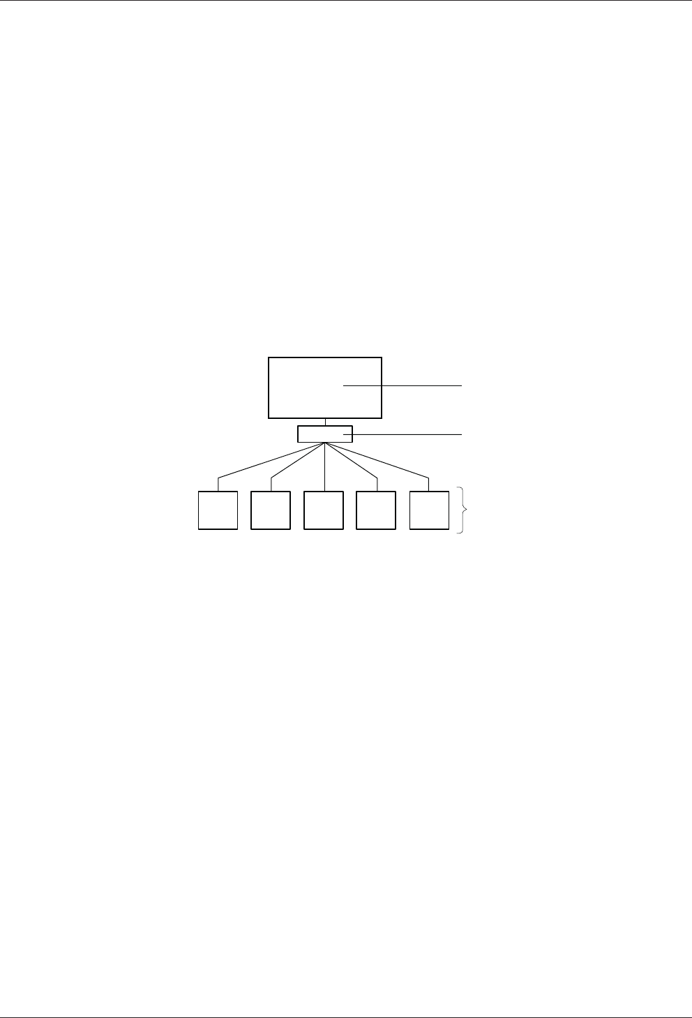
Installation Technical Manual
56 04045708 - 04/2016 Kaba Remote Reader 91 25-AM (US/
CAN)
5.4.2.3 Using several remote readers
If several Kaba remote reader 91 25 are to be connected to a host control device, ei-
ther bus wiring or star wiring can be used.
See:
• Star wiring
• Bus wiring
5.4.2.4 Star wiring
Max. eight devices can be operated on a party line.
Power supply and data line in one cable: Maximum cable length per remote reader or
stub: 20m
Power supply and data line in separate cables: Maximum data line length per remote
reader or stub: 100m
4
,7
kΩ4
,7
kΩ4
,7
kΩ 4
,7
kΩ4
,7
kΩ
120 Ω
RS-485
2
1
3
1 Host control device (Kaba access manager)
2 Distributor (e.g. screw terminal)
3 Kaba remote reader 9125
See also
Connection RS-485 [}5.4.2.2]
Set RS-485 termination resistances
Set peripheral addresses [}5.7.4]
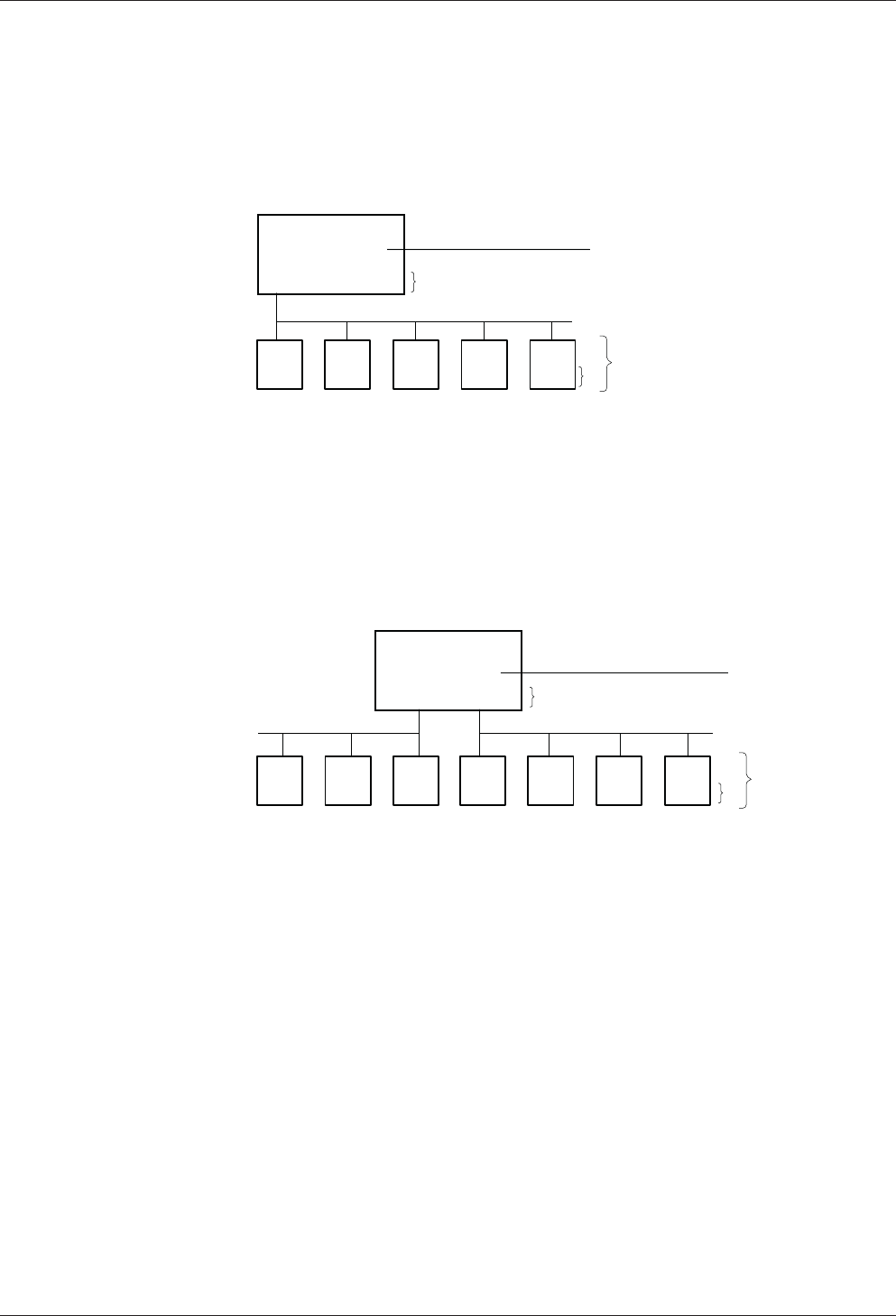
Technical Manual Installation
5704045708 - 04/2016Kaba Remote Reader 91 25-AM (US/
CAN)
5.4.2.5 Bus wiring
A maximum of eight devices can be operated on a party line.
Maximum total length of data lines (incl. stubs): 1200m
A stub itself may be a maximum of 100m in length.
The length of the party line can be increased using a repeater.
5.4.2.5.1 Bus wiring with 1 bus
120ΩOPENOPENOPENOPEN
RS-485
120 Ω
1
2
3
3
1 Host control device (Kaba access manager)
2 Kaba remote reader 91 25
3 Terminating resistors
See also
Connection RS-485 [}5.4.2.2]
Set RS-485 termination resistances
Set peripheral addresses [}5.7.4]
5.4.2.5.2 Bus wiring with two buses
120Ω120Ω
RS-485RS-485
OPEN
2
3
3
OPEN OPENOPENOPENOPEN
1
1 Host control device (Kaba access manager)
2 Kaba remote reader 91 25
3 Terminating resistors
See also
Connection RS-485 [}5.4.2.2]
Set RS-485 termination resistances
Set peripheral addresses [}5.7.4]
5.4.3 Line to the door opener and door contacts
Line requirements: Cable diameters from 0.5 mm to 0.8 mm.
Recommended cable: CAT.5 S-UTP 4 x 2 AWG 24 or AWG 22 (according to EIA/
TIA568) or higher.

Installation Technical Manual
58 04045708 - 04/2016 Kaba Remote Reader 91 25-AM (US/
CAN)
5.4.4 Coaxial Cable to the Registration Units
Cable Type
RG174/U
Coaxial cable 50Ohm, item No. 161.250
Maximum cable lengths:
Cable type RG174: up to 30m
Cable type RG178/U: up to 30m (RU 90 02: up to 10m)
Recommended ca-
ble length
< 10m
Max. cable length 30m
5.4.5 RS-232 Connection
Cable type CAT.5 S-
UTP
2 x 2 x AWG 24
Cable type J-Y (ST) 2 x 2 x 0.6mm
Max. cable length 15m
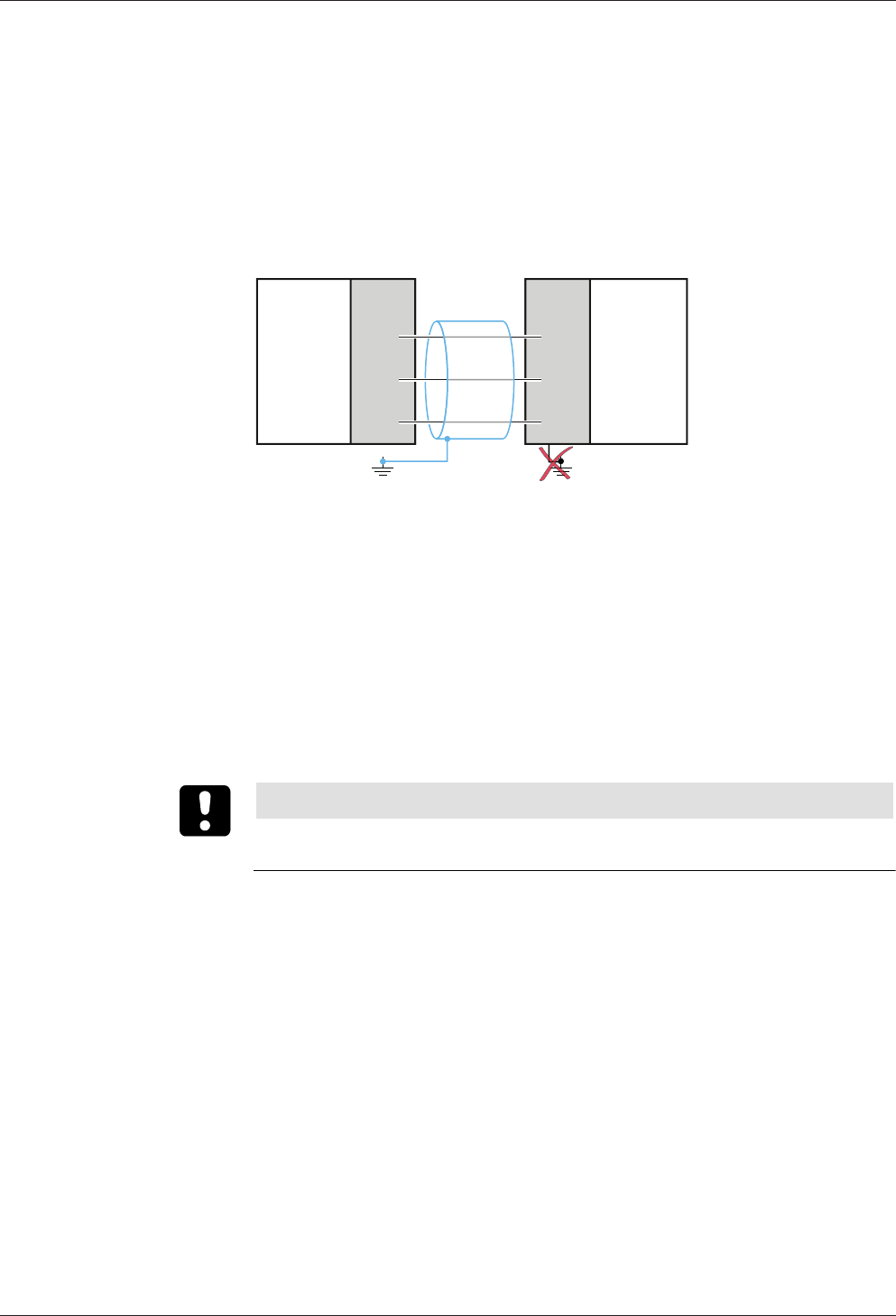
Technical Manual Installation
5904045708 - 04/2016Kaba Remote Reader 91 25-AM (US/
CAN)
5.4.6 Grounding Concept
5.4.6.1 Power supply
The divice is in a plastic housing and is not grounded.
The power supply can be operated floating or grounded.
5.4.6.2 Communication lines
1. On the host control device connect the shielding of the RS-485 cable (blue) to
the ground.
Do not ground the Kaba remote reader 91 25.
1
A
B
C
RS-485
A
B
C
RS-485
2
1 Host control device 2 Kaba remote reader 91 25
1. Connect all shieldings pertaining to the RS-485 cables used (blue) to each other.
5.4.6.3 RS-232 Connection
The RS-232 connection lines are not electrically isolated.
Measures to reduce faults:
• Use shielded cables.
• Connect the shield to the 0V line (ground) of the RS-232 connection.
5.4.6.4 Coaxial Cable Terminal
NOTICE
Inner conductor A+ and shield AS of the coaxial cable may be connected to the
ground.
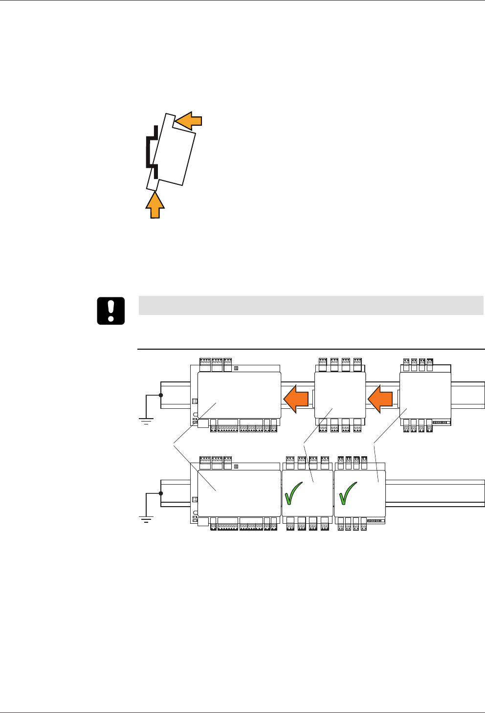
Installation Technical Manual
60 04045708 - 04/2016 Kaba Remote Reader 91 25-AM (US/
CAN)
5.5 Mounting the device and extension modules
Mount the device on a 35mm DIN rail (EN 50022).
1. Install the rail.
2. Screw grounding terminal to the rail.
Click
Push
1.
2.
3. Hang the device on the bottom of the DIN rail – without tilting – and press it up-
wards and keep it pressed.
4. Press the device upwards against the rail at the same time until it can be hung on
the rail.
Connecting extension modules
NOTICE
Attaching live extension modules may cause damage to the devices.
Always switch off the power supply before attaching the extension modules.
132
1. 2.
1 Kaba remote reader 91 25
2 Extension module 90 30
3 Extension module 90 31
1. Firstly, carefully insert all extension modules 90 30 into the device (1) or an exten-
sion module 90 30 (push the devices together on the rail).
ðAll extension modules 90 30 are inserted.
2. Then insert extension modules 90 31.
ðThe extension module 90 31 which is closer to the device (1) is designated as
module 1. The next module is designated as module 2.
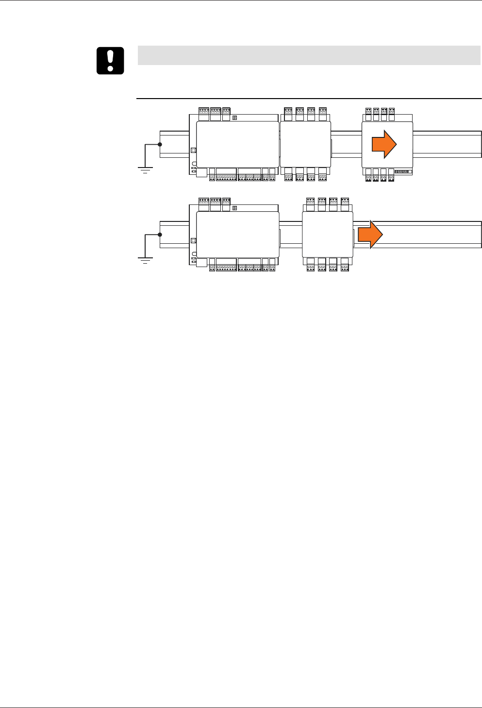
Technical Manual Installation
6104045708 - 04/2016Kaba Remote Reader 91 25-AM (US/
CAN)
Removing extension modules
NOTICE
Removing live extension modules may cause damage to the devices.
Always switch off the power supply before removing the extension modules.
1.
2.
1. Push the extension module away from the adjacent module until the contact is
fully disconnected.
2. Remove the disconnected extension module from the rail.
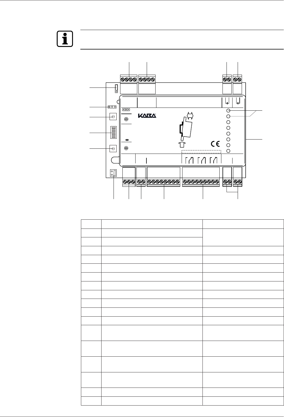
Installation Technical Manual
62 04045708 - 04/2016 Kaba Remote Reader 91 25-AM (US/
CAN)
5.6 Connections
Only connect the terminals when the power is switched off.
0
1
2
3
4
5
6
7
8
9
A
B
C
D
E
F
0
1
2
3
4
5
6
7
8
9
A
B
C
D
E
F
Mode
7
1
8 Service
ON OFF
GND
GND
GND
GND
GND
State
IN1
IN2
IN3
IN4
OUT1
OUT2
OUT3
5V
Rx
Tx
Rx
Tx
0V
IN5/TP
IN1
IN2
IN3
IN4
Vs-
Vs-
Vs+
Vs+
Function
OUT1
OUT2
OUT3
A
B
C
Supply 10-34VDCOutput max. 34VDC/27VAC/2AInput max. 5VDCRS-485
5V
0V
RS-232 B RS-232 A Ant. B Ant. A
AS
A+
AS
A+
:
Address
Prog.
Relay Output Class II
91 25
2.
1. Push
Click
DIN-Rail
91 25
0 - F
0 - F
8 7
5
6
13
14
15
16
17
1 2 3 4
9101112
Item Connection/switch Remark
1 RS-232 interface B Connection of peripherals
2 RS-232 interface A
3 Antenna B Registration unit B (antenna B)
4 Antenna A Registration unit A (antenna A)
5 LED Displays
6 Interface for Extension Modules e.g. 90 30/90 31
7 Power supply 10–34 VDC
8 Relay outputs OUT1–OUT3
9 Inputs IN1–IN4
10 Tamper switch
11 RS-485 interfaces A, B and C Connection to the host system
12 Bus termination RS-485 Jumper for adjustment of the
termination resistance
13 Addressing RS-485, 1–8 Rotary switch for selecting the
address
14 Function DIP switch for selecting the
function
15 Operating modes 'Mode' rotary switch for select-
ing the operating mode
16 Interface for Kaba programmer PD 1460
17 Not used
Technical Manual Installation
6304045708 - 04/2016Kaba Remote Reader 91 25-AM (US/
CAN)
The functions and connections of the interfaces, inputs, relay outputs, rotary and DIP
switches are described in the chapterConnecting.
5.6.1 Connections, General
Only connect the terminals when the power is switched off.
Connection Type Connection Occupancy
Pluggable screw terminals The occupancy of the connection termi-
nals can be taken from the following ta-
bles
5.6.2 Power Supply
2 x 2 clamps are available for the power supply. These are connected in parallel.
Terminal Meaning
Supply Vs+ 10–34VDC Current consumption max. 330mA, without
external wiring
Supply Vs- 0VDC
Supply voltage for
RS-232 and extension
modules at 25°C
5VDC, max. 1A
The device may only be supplied with SELV (Safety Extra Low Voltage) and LPS (Lim-
ited Power Source), according to IEC/UL/CSA 60950-1.
5.6.3 RS-485 interface
The device communicates with the host system (access hub) via the RS-485 interface.
Terminal Meaning
A RS-485 wire A
B RS-485 wire B
C RS-485 wire C (Common)
Set RS-485 termination resistances
Set peripheral addresses [}5.7.4]
5.6.4 'Ant. A' and 'Ant. B' Connections
The connections 'Ant. A' and 'Ant. B' are for the connection of the registration units to
the device. Coaxial cables are used for the connection. LED and acoustic signal trans-
mitter of the registration unit are controlled via the coaxial cable.
Terminal Meaning
A+ Antenna cable inner conductor
AS Antenna cable shield wire

Installation Technical Manual
64 04045708 - 04/2016 Kaba Remote Reader 91 25-AM (US/
CAN)
5.6.5 RS-232 A and RS-232 B Interfaces
The required power supply is provided via the Kaba remote reader 91 25.
Terminal Meaning
5V 5VDC
Rx RXD (Receive/in)
Tx TXD (Transmit/out)
0V 0V
Further information about the system-dependent functions:
• System documentation
5.6.6 Programming Interface
For connecting the Kaba programmer.
Usage:
• Firmware update, see Chapter Firmware Update/LEGIC OS Update
5.6.7 Interface for Extension Modules
For the connection of:
• Kaba extension module 90 30
• Kaba extension module 90 31
Number of Supported Extension Modules [}3.5.1]
Also see about this
23.5.1Number of Supported Extension Modules [}18]
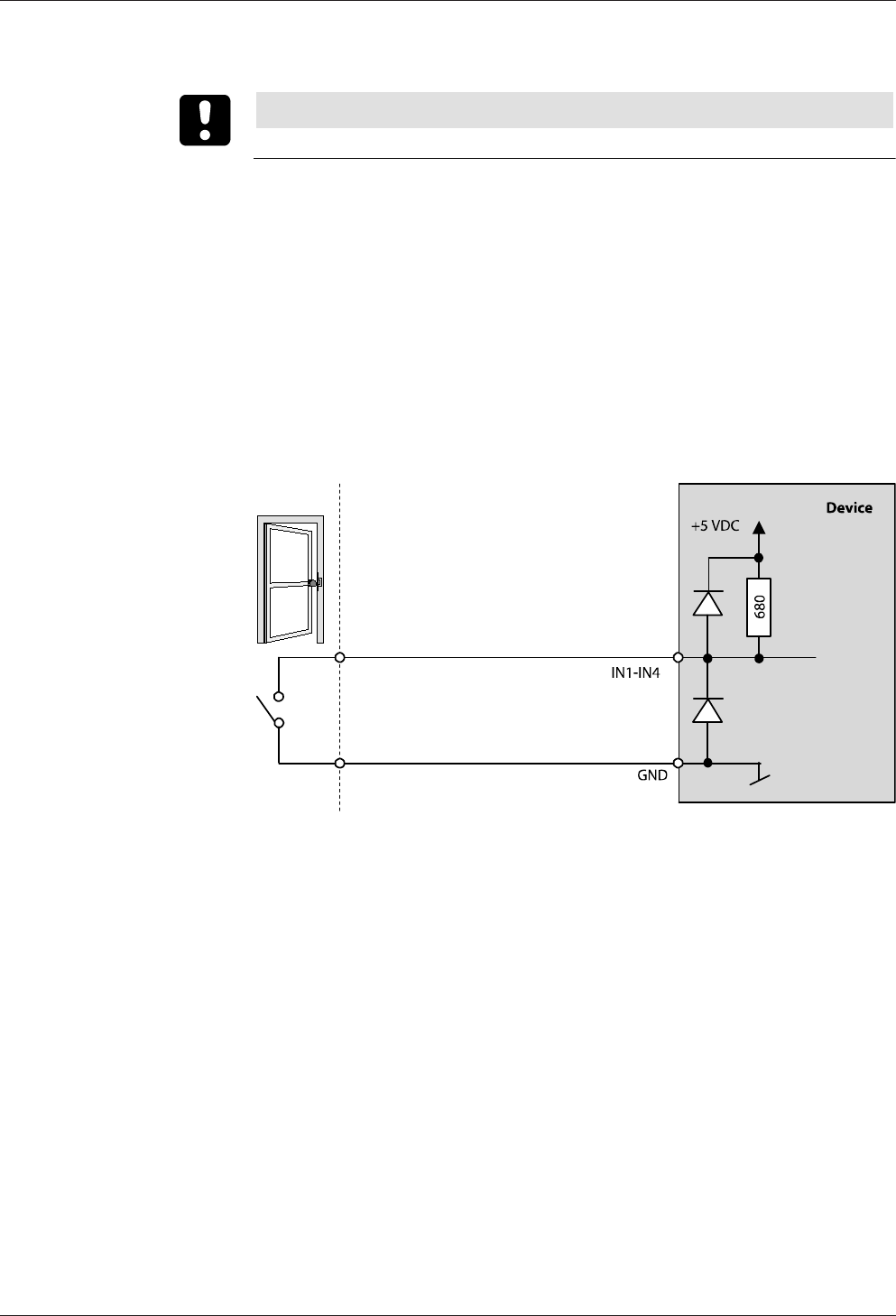
Technical Manual Installation
6504045708 - 04/2016Kaba Remote Reader 91 25-AM (US/
CAN)
5.6.8 Inputs IN1 – IN4, tamper and input 5
NOTICE
Connecting Isolated Inputs.
The logic (normally open/normally closed) of the inputs can be changed by the host
system.
If the Kaba remote reader 91 25 needs to behave in the same way in both online and
offline operation, the inputs and relay outputs must be connected according to the
operating mode and configured with the DIP switches.
IN1 and IN4 can, when necessary, be used as line-monitored inputs.
5.6.8.1 Inputs IN1 – IN4 (Without Line Monitoring)
If no inputs with line monitoring are used, no additional resistors need to be con-
nected.
Internal wiring without line monitoring

Installation Technical Manual
66 04045708 - 04/2016 Kaba Remote Reader 91 25-AM (US/
CAN)
5.6.8.2 Inputs IN1 – IN4 With Line Monitoring
Any tampering with the lines between the Kaba remote reader 91 25 and, for exam-
ple, the door frame contact is detected.
1. Activate/deactivate line monitoring:
Activate or deactivate line monitoring for each input on the host system.
2. Inputs with line monitoring:
Attach resistors (R=680 Ω, ¼ W 2%), ensuring they are tamper-proof.
IN1-IN4
GND
1
2
+5 V DC
680 Ω
680 Ω
680 Ω
1 Kaba remote reader 91 25
2 Tamper-proof area
3. Using inputs with and without line monitoring at the same time:
No resistors need to be connected to lines without line monitoring.
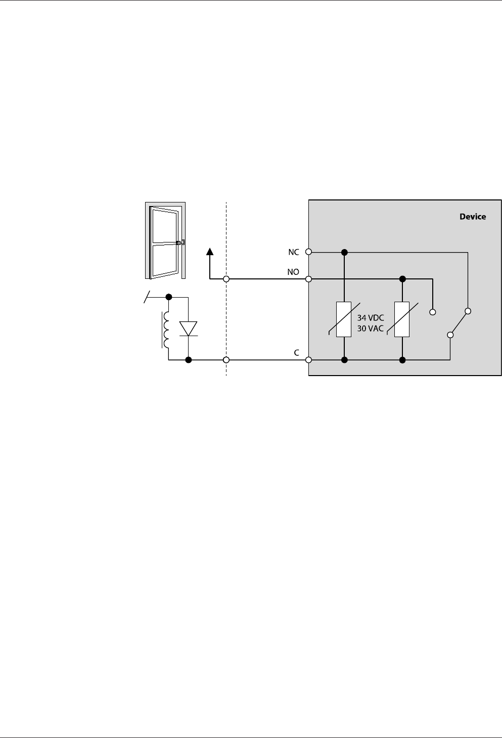
Technical Manual Installation
6704045708 - 04/2016Kaba Remote Reader 91 25-AM (US/
CAN)
5.6.8.3 Input Tamper
The input tamper is connected as a line-monitored input. Its logical status is enabled
open. If the Kaba remote reader 91 25 is offline and the tamper enabled, this event is
entered in the logbook of the Kaba remote reader 91 25.
5.6.8.4 Input IN5 (only in the Kaba exos lock operating mode)
Input 5 is an internal input for the door handle contact of the Kaba exos lock. The sig-
nal is transferred via the coaxial cable and evaluated in the Kaba remote reader 91 25
as input 5.
5.6.9 Output OUT1 – OUT3
Usage e.g.:
• electric strike
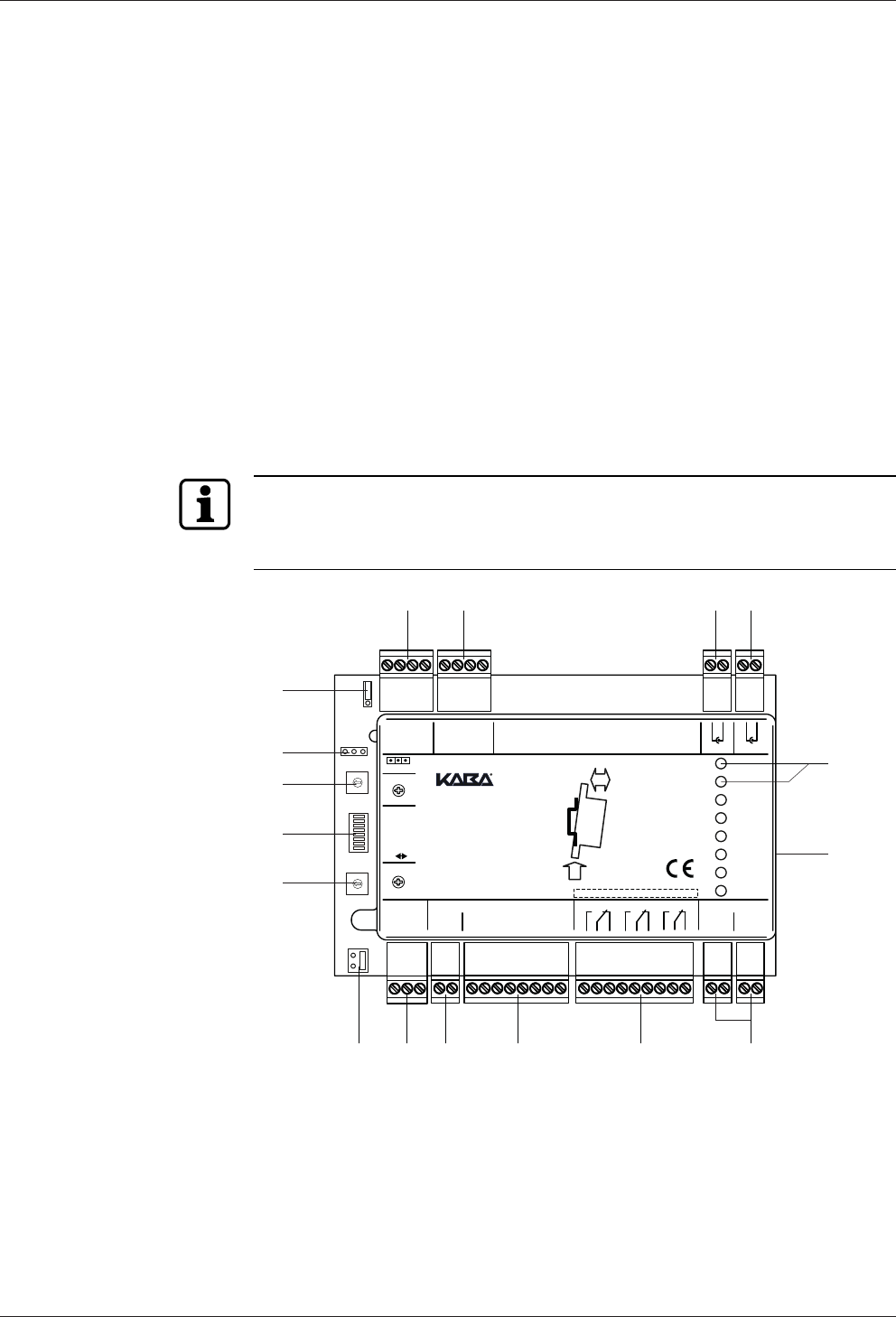
Installation Technical Manual
68 04045708 - 04/2016 Kaba Remote Reader 91 25-AM (US/
CAN)
5.7 Configuring
5.7.1 Configuration process
1. Set address of the Kaba remote reader 91 25, see chapter
Addressing.
Note down the address. It is required for the configuration in the host system.
2. Set termination resistance on the RS-485 bus as per the bus topology, see chap-
ter
Bus termination RS-485
3. Set operating mode according to the door configuration, see chapter
Set Operating Mode
4. Set extended functions for the selected operating mode, see chapter
Extended functions of the operating modes [}5.7.6.1]
5. Activate or deactivate monitoring of all inputs, see chapter
Activate monitoring of all inputs (DIP switch 7)
5.7.2 Change Settings
Jumper, DIP switch and rotary switch settings must only be made when the power is
switched off.
Changes of jumper-, DIP switch- and rotary switch settings are only activated after
turning on the power supply (cold start).
0
1
2
3
4
5
6
7
8
9
A
B
C
D
E
F
0
1
2
3
4
5
6
7
8
9
A
B
C
D
E
F
Mode
7
1
8 Service
ON OFF
GND
GND
GND
GND
GND
State
IN1
IN2
IN3
IN4
OUT1
OUT2
OUT3
5V
Rx
Tx
Rx
Tx
0V
IN5/TP
IN1
IN2
IN3
IN4
Vs-
Vs-
Vs+
Vs+
Function
OUT1
OUT2
OUT3
A
B
C
Supply 10-34VDCOutput max. 34VDC/27VAC/2AInput max. 5VDCRS-485
5V
0V
RS-232 B RS-232 A Ant. B Ant. A
AS
A+
AS
A+
:
Address
Prog.
Relay Output Class II
91 25
2.
1. Push
Click
DIN-Rail
91 25
0 - F
0 - F
8 7
5
6
13
14
15
16
17
1 2 3 4
9101112
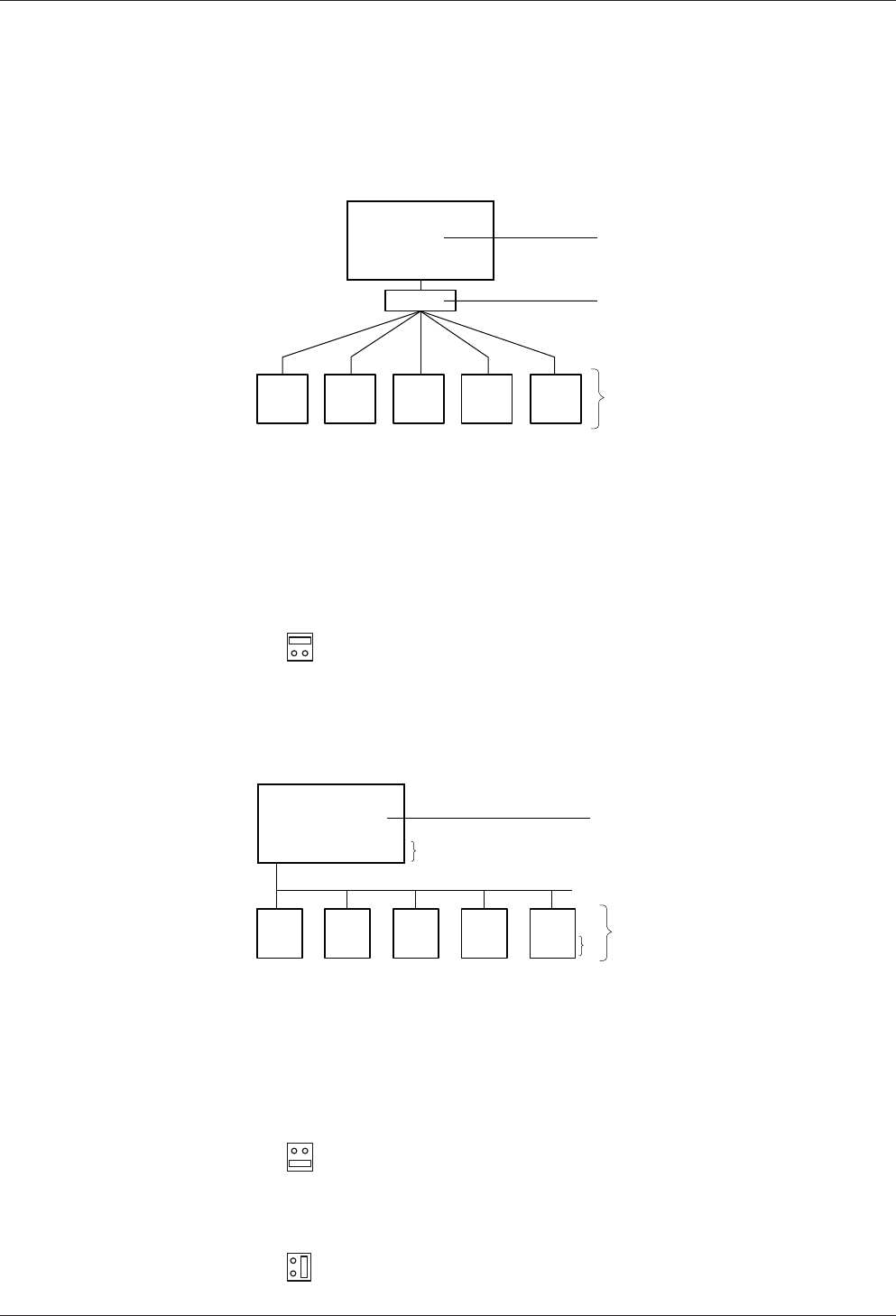
Technical Manual Installation
6904045708 - 04/2016Kaba Remote Reader 91 25-AM (US/
CAN)
5.7.3 Set RS-485 termination resistances
The connection architecture determines the terminating resistors.
Star wiring
4
,7
kΩ4
,7
kΩ4
,7
kΩ 4
,7
kΩ4
,7
kΩ
120 Ω
RS-485
2
1
3
1 Host control device (Kaba access manager AM)
2 Distributor (e.g. screw terminal)
3 Terminating resistors Kaba remote reader 9125
1. Set the terminating resistor to 4.7kΩ on the Kaba remote reader 9125 using the
jumper (12).
2. Set the terminating resistor to 120Ω on the host control system (1).
Bus wiring with 1 bus
120ΩOPENOPENOPENOPEN
RS-485
120 Ω
1
2
3
3
1 Host control device (Kaba access manager AM)
2 Kaba remote reader 9125
3 Terminating resistors
1. Set the terminating resistor to 120Ω on the last Kaba remote reader 9125 of the
bus wiring.
2. Set the terminating resistor to open on all other Kaba remote reader 9125 of the
bus wiring.

Installation Technical Manual
70 04045708 - 04/2016 Kaba Remote Reader 91 25-AM (US/
CAN)
3. Set the terminating resistor to 120Ω on the host control system.
Bus wiring with two buses
120Ω120Ω
RS-485RS-485
OPEN
2
3
3
OPEN OPENOPENOPENOPEN
1
1 Host control device (Kaba access manager AM)
2 Kaba remote reader 9125
3 Terminating resistors
1. Set the terminating resistor to 120Ω on both terminal devices of the bus wiring.
2. Set the terminating resistor to open on all other Kaba remote reader 9125 of the
bus wiring.
3. Set the terminating resistor to open on the host control system.
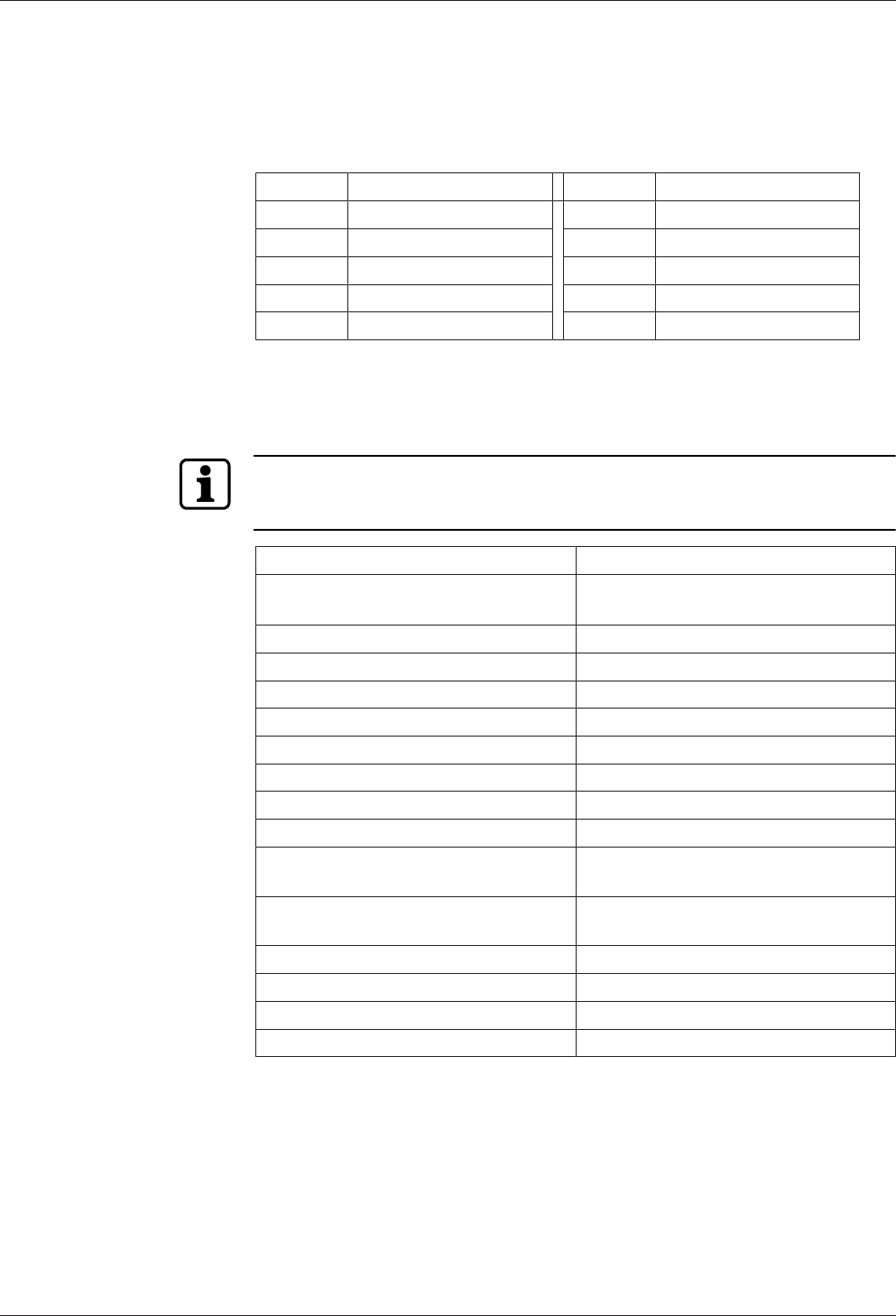
Technical Manual Installation
7104045708 - 04/2016Kaba Remote Reader 91 25-AM (US/
CAN)
5.7.4 Set peripheral addresses
Each device connected to an RS-485 bus must have a unique address.
1. Assign the Kaba remote reader 91 25 with rotary switch (13) a unique peripheral
address.
Position Peripheral address Position Peripheral address
0 Default, not used 5 5
1 1 6 6
2 2 7 7
3 3 8 8
4 4 9–F Not used
5.7.5 Set Operating Mode
The door configuration determines the operating mode of the Kaba remote reader
91 25.
The operating mode is set with the rotary switch (15).
In order to define the offline behavior of the device, the "extended functions" must
be set in addition to the operating mode. The Chapter [}5.7.6.1] explains the ex-
tended functions.
Kaba remote reader 91 25
Position
Rotary switch
Operating mode
0 Electric strike
1 Motor bolt
2 Automatic door
3 Turnstile
4 Night lock
5 Kabaexos lock
6 Cylinder interface LI-EL
7 Motor bolt with panic function
8 Motor bolt type II with panic function (2
outputs)
9 Motor bolt type III with panic function (1
output)
A Electric lock with panic function
B Automatic door with night lock
C–E Not used
F Online operation
The chapter Operating modes [}4.9] describes the operating modes.
Installation Technical Manual
72 04045708 - 04/2016 Kaba Remote Reader 91 25-AM (US/
CAN)
5.7.6 Set functions
The following functions can be set with the DIP switches (14):
DIP switch
Number
Function
1–6 Extended functions (according to operating modes)
7 Not used
8 ON Service mode
5.7.6.1 Extended functions of the operating modes
The DIP switches 1–6 (14) are used to set the extended functions of the operating
modes.
The chapter Operating modes describes the operating modes.
If the Kaba remote reader 91 25 needs to behave in the same way in both online and
offline operation, the inputs and relay outputs must be connected according to the
operating mode and configured with the DIP switches.
The parameterization of the access point must match the selected configuration in
the host system. See also chapter Operating Types [}4.8]
NOTICE
The DIP switches should only be put to ON if the relevant component is also con-
nected to the device.
The following chapters describe the individual operating modes with their connec-
tions and configurations.

Technical Manual Installation
7304045708 - 04/2016Kaba Remote Reader 91 25-AM (US/
CAN)
5.7.6.1.1 Operating Mode 0; Electric Strike
Access point Designation Connection/function DIP switch
ON
Outside Ant. A Registration unit A -
RS-232 A Optional -
Ant. A Hold-open mode DIP 2
Door OUT1 Electric strike -
OUT2 Authorized access DIP 1
IN2 Frame contact DIP 4
IN3 Blocking contact DIP 5
OUT3 Alarm buzzer DIP 6
Inside Ant. B Registration unit B -
RS-232 B Optional -
IN1 Door opener key DIP 3
- IN4 Freely available (only on-
line)
-
5.7.6.1.2 Operating Mode 1; Motor Bolt
Access point Designation Connection/function DIP switch
ON
Outside Ant. A Registration unit A -
RS-232 A Optional -
Ant. A Hold-open mode DIP 2
Door OUT1 Motor bolt -
IN4 Deadbolt contact (locked) -
OUT2 Authorized access DIP 1
IN2 Frame contact DIP 4
IN3 Blocking contact DIP 5
OUT3 Alarm buzzer DIP 6
Inside Ant. B Registration unit B -
RS-232 B Optional -
IN1 Door opener key DIP 3
5.7.6.1.3 Operating Mode 2; Automatic Doors
Access point Designation Connection/function DIP switch
ON
Outside Ant. A Registration unit A -
RS-232 A Optional -
Door OUT1 Enable pulse for automatic
door
-
OUT2 Authorized access DIP 1
IN2 Frame contact DIP 4
IN3 Blocking contact DIP 5
OUT3 Alarm buzzer DIP 6

Installation Technical Manual
74 04045708 - 04/2016 Kaba Remote Reader 91 25-AM (US/
CAN)
Access point Designation Connection/function DIP switch
ON
Inside Ant. B Registration unit B -
RS-232 B Optional -
IN1 Door opener key DIP 3
- IN4 Freely available -

Technical Manual Installation
7504045708 - 04/2016Kaba Remote Reader 91 25-AM (US/
CAN)
5.7.6.1.4 Operating Mode 3; Turnstile
Access point Designation Connection/function DIP switch
ON
Outside Ant. A Registration unit A -
RS-232 A Optional -
OUT1 Direction-dependent en-
able pulse
-
Door OUT2 Authorized access DIP 1
IN2 Frame contact DIP 4
IN3 Blocking contact DIP 5
Inside Ant. B Registration unit B -
RS-232 B Optional -
OUT3 Direction-dependent en-
able pulse
-
IN1 Door opener key DIP 3
- IN4 Freely available -
5.7.6.1.5 Operating Mode 4; Night Lock
Access point Designation Connection/function DIP switch
ON
Outside Ant. A Registration unit A -
RS-232 A Optional -
Ant. A Hold-open mode DIP 2
Door OUT1 Electric strike -
OUT3 Motor bolt -
IN4 Deadbolt contact -
OUT2 Authorized access DIP 1
IN2 Frame contact DIP 4
IN3 Blocking contact DIP 5
Inside Ant. B Registration unit B -
RS-232 B Optional -
IN1 Door opener key DIP 3

Installation Technical Manual
76 04045708 - 04/2016 Kaba Remote Reader 91 25-AM (US/
CAN)
5.7.6.1.6 Operating Mode 7; Motor Bolt with Panic Function
Access point Designation Connection/function DIP switch
ON
Outside Ant. A Registration unit A -
RS-232 A Optional -
Ant. A Hold-open mode DIP 2
Door OUT1 Motor bolt -
IN4 Deadbolt contact (locked) -
OUT2 Authorized access DIP 1
IN2 Frame contact DIP 4
IN3 Blocking contact DIP 5
OUT3 Alarm buzzer DIP 6
Inside Ant. B Registration unit B -
RS-232 B Optional -
IN1 Door handle contact DIP 3
5.7.6.1.7 Operating Mode 8; Motor bolt type II with panic function (2 outputs)
Access point Designation Connection/function DIP switch
ON
Outside Ant. A Registration unit A -
RS-232 A Optional -
Ant. A Hold-open mode DIP 2
Door OUT1 Lock motor bolt -
OUT3 Unlock motor bolt -
IN4 Deadbolt contact (locked) -
OUT2 Authorized access DIP 1
IN2 Frame contact DIP 4
IN3 Blocking contact DIP 5
Inside Ant. B Registration unit B -
RS-232 B Optional -
IN1 Door handle contact DIP 3

Technical Manual Installation
7704045708 - 04/2016Kaba Remote Reader 91 25-AM (US/
CAN)
5.7.6.1.8 Operating Mode 9; Motor bolt type III with panic function (1 output)
Access point Designation Connection/function DIP switch
ON
Outside Ant. A Registration unit A -
RS-232 A Optional -
Ant. A Hold-open mode DIP 2
Door OUT1 Motor bolt -
IN4 Deadbolt contact (locked) -
OUT2 Authorized access DIP 1
IN2 Frame contact DIP 4
IN3 Blocking contact DIP 5
OUT3 Alarm buzzer DIP 6
Inside Ant. B Registration unit B -
RS-232 B Optional -
IN1 Door handle contact DIP 3

Installation Technical Manual
78 04045708 - 04/2016 Kaba Remote Reader 91 25-AM (US/
CAN)
5.7.6.1.9 Operating Mode A; Electric Lock with Panic Function
Access point Designation Connection/function DIP switch
ON
Outside Ant. A Registration unit A -
RS-232 A Optional -
Ant. A Hold-open mode DIP 2
Door OUT1 Electric lock -
IN4 Deadbolt contact (locked) -
OUT2 Authorized access DIP 1
IN2 Frame contact DIP 4
IN3 Blocking contact DIP 5
OUT3 Alarm buzzer DIP 6
Inside Ant. B Registration unit B -
RS-232 B Optional -
IN1 Door handle contact DIP 3 off
IN1 Door opener key DIP 3 on
5.7.6.1.1
0
Operating Mode B; Automatic Door with Night Lock
Access point Designation Connection/function DIP switch
ON
Outside Ant. A Registration unit A -
RS-232 A Optional -
Ant. A Hold-open mode DIP 2
Door OUT1 Enable pulse for automatic
door
-
OUT3 Motor bolt -
IN4 Deadbolt contact -
OUT2 Authorized access DIP 1
IN2 Frame contact DIP 4
IN3 Blocking contact DIP 5
Inside Ant. B Registration unit B -
RS-232 B Optional -
IN1 Door opener key DIP 3
5.7.6.2 Hold-open mode (DIP switch 2)
In hold-open mode, the door remains open upon an authorized access (identifica-
tion) for as long as the badge remains within range of the antenna (field). The hold-
open mode only works without PIN entry. Kaba exos lock and cylinder interface LI-EL
are not supported.
• Hold-open mode applies for antenna A and antenna B
Technical Manual Installation
7904045708 - 04/2016Kaba Remote Reader 91 25-AM (US/
CAN)
5.7.6.3 Activate the monitoring of inputs
Line monitoring can only be activated and deactivated by the host system.
The position of DIP switch 7 does not affect line monitoring.
5.7.6.4 Service mode (DIP switch 8)
Service mode is only used for service, e.g. for
• commissioning Hyper X
• Reset Kaba remote reader 91 25 to the basic status, see Chapter
DIP switch 8 activates service mode.
DIP switch position Meaning
ON Service mode activated
OFF Service mode deactivated
If the device is in service mode, then the access point is blocked and no configura-
tion data will be accepted.

Start-up Technical Manual
80 04045708 - 04/2016 Kaba Remote Reader 91 25-AM (US/
CAN)
6 Start-up
6.1 Putting into operation process
üThe device is installed.
Installation process [}5.1]
üThe device is configured.
Configuring
1. Reset device to its basic state.
Factory Reset/Reset Device to the Basic Status
2. Connect the power supply to the Kaba remote reader 91 25, see chapter
Power Supply [}5.6.2]
ðLED state illuminates green – LED state flashes green as soon as the RS-485
interface is in the receive or send mode (online).
3. Put the device into operation in accordance with the following chapter.
6.2 "Standalone Access Control without Host System" Commissioning
(Construction site mode)
The Remotereader can already be used on a host system even before connection.
This allows for the use of the remote reader, e.g., during the construction phase.
By connecting the remote reader to a host control device (host system), the func-
tions of the remote reader described in this chapter are replaced by parameteriza-
tion of the system.
Also see about this
21.4Supplementary Documents [}8]
6.2.1 Using LEGIC
If using "Standalone access control (without host system)", only the LEGIC stamp
(segment search key) is checked. To authorize access, the user medium's stamp must
match the stamp of the remote reader.
• If using "Standalone access control (without host system)" the remote reader can
only be used with one stamp (segment search key).
Preparation
1. Use security cardC1 (IAM) to define the stamp of masterA (only LEGIC ISO
14443A) (see RM_LEGIC_advant_Media_Definition).
Putting into operation
1. Carry out factory reset on the remote reader, see Chapter
2. Present Master A (only LEGIC ISO 14443A) to the connected registration unit.
ðIn the event of successful transfer of the stamp: 3x short beep
ðThe stamp (segment search key) was transferred onto the remote reader.
ðThe remote reader is now ready for bookings.
Functions
• Book
• Save the following events (max. 2000):
– Door forced open

Technical Manual Start-up
8104045708 - 04/2016Kaba Remote Reader 91 25-AM (US/
CAN)
– Doors opened using the button/door handle
– Door open too long
• Not saved:
– Access events
– The time and date stamps are incorrect/invalid because the clock on the re-
mote reader has not been set yet.
Book
1. Present a LEGIC user medium (LEGIC prime, ISO 14443A or ISO 15693) to the con-
nected registration unit.
ðIf the stamp (segment search key) of the remote reader matches a stamp of
the user medium: Access authorized
Connection to the host control device (host system)
After connecting the remote reader to the host control device (host system), the
saved events are sent to the control device. The time and date stamps are not cor-
rect/invalid because the clock of the remote reader had not yet been set (at the time
the events were saved).
6.2.2 Using MIFARE
If using "Standalone access control (without host system)", only the site key/fabrica-
tion key is checked. During the check, the medium's fabrication key is not replaced.
To authorize access, the user medium's site key must match one of the remote
reader's site keys.
• A security cardC, a masterA, or a masterB medium can contain up to eight site
keys.
• On the medium, the site key's identification file must match the "default ARIOS
configuration"; the applicationID, fileID, and coding of the identification number
must match. Media with changed applicationIDs or non-standard identification
number coding will not be recognized.
Putting into operation
1. Carry out factory reset on the remote reader, see Chapter
2. Hold security card C, a master A or a master B medium in front of the connected
registration unit.
ðIn the event of successful transfer of the stamp: 3x short beep
ðA maximum of eight site keys are transferred onto the remote reader.
ðThe remote reader is now ready for bookings.
Functions
• Book
• Save the following events (max. 2000):
– Door forced open
– Doors opened using the button/door handle
– Door open too long
• Not saved:
– Access events
– The time and date stamps are incorrect/invalid because the clock on the re-
mote reader has not been set yet.

Start-up Technical Manual
82 04045708 - 04/2016 Kaba Remote Reader 91 25-AM (US/
CAN)
Book
1. Present a MIFARE user medium (MIFARE DESFire or MIFARE Classic) to the con-
nected registration unit.
ðIf the user medium's site key matches one of the remote reader's site keys:
Access authorized
Connection to the host control device (host system)
After connecting the remote reader to the host control device (host system), the
saved events are sent to the control device. The time and date stamps are not cor-
rect/invalid because the clock of the remote reader had not yet been set (at the time
the events were saved).

Technical Manual Start-up
8304045708 - 04/2016Kaba Remote Reader 91 25-AM (US/
CAN)
6.3 Functional Test (RS-232 A/B)
Requirements
• Remote reader is installed and connected, see Chapter Installing and Connecting
• Remote reader is configured, see Chapter Configuring
• Remote reader is parameterized, see Chapter Parameterizing
• Remote reader is connected to the power supply, see Chapter Connect Power
Supply
Functions
If the requirements listed above are met, then the parent control unit informs the re-
mote reader which units are connected to the RS-232 interface. The remote reader
communicates with the connected units according to the settings. The remote
reader stores the settings of the connected units. The Chapter Factory Reset/Reset
Device to the Basic Status describes the deletion of this stored settings.
Commissioning Hyper X
• For the commissioning of a Hyper X, the distributor code must be scanned with a
booking in service mode.

Start-up Technical Manual
84 04045708 - 04/2016 Kaba Remote Reader 91 25-AM (US/
CAN)
6.4 Issue Write/Read Authorization (Launch)
A write/read authorization is required in the following cases:
• If the Remotereader needs to write on a write-protected segment of a medium,
e.g. in the case of CardLink applications, validate write-protected CardLink seg-
ments
• If the Remotereader needs to read a read-protected segment of a medium
In this chapter, the term "Write authorization" will be used for the terms "Write au-
thorization" and "Read authorization".
Write authorization with a LEGIC prime SAM 63 card is only valid for LEGIC prime.
Write authorization with a LEGIC advant SAM 63 card is only valid for LEGIC prime
and LEGIC advant 15693 and 14443A.
In this chapter, the designation "Security card C2" will be used for the card designa-
tions "SAM 63" and "Security card C2 (SC-C2)".
The signaling is carried via the registration unit on which the card is presented.
Requirement
• For the write authorization, a security card C2 with corresponding segment area
is required.
• ISO standard 14443A must have been activated using security card C2.
• The ISO standard of the SAM 63 card must match the parameterized ISO stan-
dard.
• The device should be in regular operation and waiting for an RFID entry.
Procedure
1. Present the security card C2 to the connected registration unit without interrup-
tion (approx. 15s).
ðThe Registration unit illuminates green during the process.
ðSignaling after successful write authorization: 3x beeps
If the Remotereader has previously been granted write authorization using
the same security card C2, this will be signaled immediately by 3x beeps
No indications are made on the exos lock or cylinder interface LI-EL following
successful write authorization.
ðNo signaling: Write authorization has not been granted.
Possible reasons
- The security card C2 was removed from the RFID field too early
- ISO 14443A is not activated in the system
- If SAM+ media are being used: No credit is available
2. Remove the security card C2 from the field.

Technical Manual Start-up
8504045708 - 04/2016Kaba Remote Reader 91 25-AM (US/
CAN)
6.5 Cancel Write/Read Authorization
The write/read authorization needs to be canceled in the following cases:
• If the Remotereader no longer needs to write on write-protected segments of a
medium
• If the Remotereader no longer needs to read read-protected segments of a
medium
In this chapter, the term "Write authorization" will be used for the terms "Write au-
thorization" and "Read authorization".
In this chapter, the term "Writing right" will be used for the terms "Writing right" and
"Reading right".
6.5.1 Cancel all writing rights granted by a write authorization
1. Reset remote reader to the basic status, see Chapter
6.5.2 Cancel a particular writing right granted by a write authorization:
Use the SAM 64 card to delete the relevant stamp.
The signaling is carried via the registration unit on which the card is presented.
Requirement
• In order to cancel the write authorization, a SAM 64 card with the relevant seg-
ment range is required.
• The device is in normal operation and waits for an RFID entry.
Procedure
1. Present the SAM 64 card to the connected registration unit without interruption
(approx. 15s).
ðThe Registration unit illuminates green during the process.
ðSignaling after successful cancellation of the write authorization:
3x Beep
If the write authorization has already previously been canceled with the
same SAM 64 card, this will be signaled immediately with 3x beeps.
ðNo signaling: unsuccessful cancellation of write authorization
Possible reasons
- The SAM 64 card was removed from the RFID field too early (no signaling)
- ISO 14443A is not enabled in the system
- If SAM+ media are used: there are no credits available
2. Remove the SAM 64 card from the field.
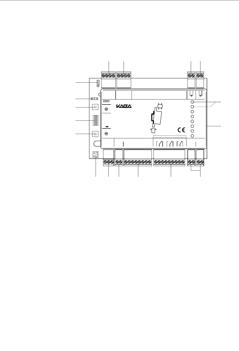
Servicing Technical Manual
86 04045708 - 04/2016 Kaba Remote Reader 91 25-AM (US/
CAN)
7 Servicing
7.1 Programming interface
A 3-pin connection (16) to connect to the Kaba programmer 1460 is located on the
front of the Kaba remote reader 91 25. The connection (16) is used to update the
firmware.
0
1
2
3
4
5
6
7
8
9
A
B
C
D
E
F
0
1
2
3
4
5
6
7
8
9
A
B
C
D
E
F
Mode
7
1
8 Service
ON OFF
GND
GND
GND
GND
GND
State
IN1
IN2
IN3
IN4
OUT1
OUT2
OUT3
5V
Rx
Tx
Rx
Tx
0V
IN5/TP
IN1
IN2
IN3
IN4
Vs-
Vs-
Vs+
Vs+
Function
OUT1
OUT2
OUT3
A
B
C
Supply 10-34VDCOutput max. 34VDC/27VAC/2AInput max. 5VDCRS-485
5V
0V
RS-232 B RS-232 A Ant. B Ant. A
AS
A+
AS
A+
:
Address
Prog.
Relay Output Class II
91 25
2.
1. Push
Click
DIN-Rail
91 25
0 - F
0 - F
8 7
5
6
13
14
15
16
17
1 2 3 4
9101112
7.2 Restart
Consequences of the restart
• Duration approx. 3 seconds
• The access point is blocked during the restart.
• The saved parameter settings and data remain in place.
• The device is restarted.
1. Switch the power supply off and on again.
ðThe LED state goes out.
ðThe access point is blocked.
2. After the restart, the LED state changes back to green.
ðOffline mode: If the device is parameterized for offline mode, the access
point is now ready for bookings.
ðOnline mode: After the connection has been set up with the host control
device, the remote reader is ready for operation in online mode.
Restarting resets the internal clock. After restarting, the clock will read 01/01/2010
00:00. Logbook entries will be saved with an incorrect date stamp as a result until the
next online operation.

Technical Manual Servicing
8704045708 - 04/2016Kaba Remote Reader 91 25-AM (US/
CAN)
7.3 Service mode
Service mode is part ...
• of the factory reset
• of the firmware update
7.3.1 Enable service mode
Procedure
1. Disconnect device from the power supply
ðThe access point is blocked while in service mode
2. If the write authorization has to be canceled: set 'Mode' rotary switch to 'F'
3. Set DIP switch 8 to 'ON' (in the event of uninterrupted power supply, a change in
the status of the DIP switch has no effect)
ðService mode is activated
7.3.2 Disable service mode
Procedure
1. Disconnect device from the power supply
2. Set DIP switch 8 to 'OFF'.
ðService mode is deactivated

Servicing Technical Manual
88 04045708 - 04/2016 Kaba Remote Reader 91 25-AM (US/
CAN)
7.4 Factory Reset/Reset Device to the Basic Status
Consequences of the factory reset
• The device is returned to its basic state (factory settings).
• The parameter settings are deleted.
• If the Mode rotary switch is set to F, the write authorization (launch data) will be
deleted.
• The stamps are deleted.
• The factory reset lasts approximately 3seconds.
• The access point is blocked during the factory reset.
The factory reset is controlled by the following switches:
• DIP switch for selecting the function, see chapterDevice structure
• 'Mode' rotary switch for selecting the operating mode, see chapter Device struc-
ture
Procedure Signaling
Remote reader
Signaling
Registration unit
1. Disconnect the device from the power supply.
• The access point is blocked during the factory re-
set.
2. If the write authorization is to be deleted (launch
data): Set 'Mode' rotary switch to F
3. Set DIP switch 8 to ON.
(Switching the DIP switch when the power supply is
connected has no effect).
• Service mode is activated.
4. Connect the device to the power supply.
• Device is reset to the factory settings (for further
effects, see above, consequences of the factory
reset).
2 x short beep, then red/
green flashing
State: permanent orange
IN1–IN4: permanent or-
ange
If 'Mode' rotary switch is
set to 'F'*:
OUT1–3: permanent red
5. Wait until the IN LEDs flash orange.
6. Disconnect the device from the power supply.
7. Set DIP switch 8 to OFF.
• Service mode is deactivated.
8. Set the desired operating mode on the 'Mode' rotary
switch.
9. Connect device to the power supply.

Technical Manual Servicing
8904045708 - 04/2016Kaba Remote Reader 91 25-AM (US/
CAN)
• The device is in operation again.
• In the event of online connection: The host con-
trol device loads the current parameters on the
remote reader.
• The access point is ready for bookings.
State: permanent green
or flashing green
permanent green
* The write authorization (launch data) is deleted.

Servicing Technical Manual
90 04045708 - 04/2016 Kaba Remote Reader 91 25-AM (US/
CAN)
7.5 Firmware Update/LEGIC OS Update
An update can be performed in the following ways:
• Using the access manager service tool via access manager (via Ethernet and the
RS-485 interface)
• Using the Kaba EAC service tool and programmer 1460
NOTICE
Consequences of the firmware update:
• Device is reset to the factory settings(basic status)
• The parameterization is deleted
• The data is deleted
• The stamps are deleted
7.5.1 Firmware update/LEGIC OS update via access manager
The firmware/LEGIC OS is updated using the access manager service tool via access
manager (via Ethernet and the RS-485 interface). The access manager reference man-
ual describes the process.
7.5.2 Firmware Update / LEGIC OS Update with programmer 1460
The firmware update/LEGICOS update lasts around 120 seconds.
Requirements
• The firmware has been transferred from the Kaba EAC service tool to the programmer 1460 (the LEGIC OS is in-
tegrated into the firmware).
• The user is familiar with the handling of the programmer and the Kaba EAC service tool.
• Kaba EAC service tool ≥ V 2.6.1 is installed.
• FTDI driver (using the operating system) for Kaba programmer 1460 is installed (FTDI CDM supports D2XX and
VCP functionality) http://www.ftdichip.com/FTDrivers.htm
• Microsoft .Net Framework 4 Client Profile is installed http://www.microsoft.com/net/
Procedure Signaling
Remote reader
Signaling
Registration unit
1. Disconnect the device from the power
supply.
(Switching DIP switch 8 when the
power supply is connected has no ef-
fect.)
• The access point is blocked during
the firmware update.
2. Turn DIP switch 8 to ON.
• Service mode is activated.
3. Connect the device to the power sup-
ply.

Technical Manual Servicing
9104045708 - 04/2016Kaba Remote Reader 91 25-AM (US/
CAN)
IN1–4 flash orange 2 x short beep, then alternate
red/green flashing
If the programmer is connected
before switching on the power
supply, then there is no flashing.
If the programmer is connected
before switching on the power
supply, then there is no flashing.
4. Connect the programmer to the device
using the programming cable.
LED off or permanent orange LED off
NOTICE
During the firmware update, the power supply and the connection to the program-
mer must not be interrupted.
5. On the programmer, select the
firmware to be transferred and then
download.
After successful download:
6. Disconnect the device from the power
supply.
If the programmer is removed
before the power supply is inter-
rupted, then the LEDs flash ac-
cording to the update mode.
If the programmer is removed
before the power supply is inter-
rupted, then the LEDs flash ac-
cording to the update mode.
7. Set DIP switch 8 to OFF.
• Service mode is deactivated.
8. Disconnect the programmer from the
device.
9. Connect the device to the power sup-
ply.
• The device is in operation again.
• In the event of online connection:
The host control device loads the
current parameters on the remote
reader.
• The access point is ready for book-
ings.
State: permanent green or flash-
ing green
permanent green
The settings of the rotary switch (operating modes, addressing) have no influence on
the service mode.

Servicing Technical Manual
92 04045708 - 04/2016 Kaba Remote Reader 91 25-AM (US/
CAN)
7.6 Crossgrade
A crossgrade can be used to amend the functional type of a device. For example, a
device with the functional type access manager (AM) can be turned into a device
with the functional type AMC.
The process for changing the functional type is described in the user manual for Kaba
programmer1460, document nok1evo809.
7.6.1 Device with Bxxx firmware (MRD)
Remote reader type before
crossgrade
Remote reader type after
crossgrade
Functional
type
Functional
type
MRD
(multi RFID de-
vice)
• AM
• AMC
Crossgrade
⇨
MRD
(multi RFID de-
vice)
• AMC
• AM
Illustrative example
Only Bxxx firmware (MRD) can be transferred to a device with Bxxx firmware (MRD).
It is possible to change functional type.
It is possible to change between LEGIC and MIFARE.

Technical Manual Troubleshooting
9304045708 - 04/2016Kaba Remote Reader 91 25-AM (US/
CAN)
8 Troubleshooting
8.1 LED Displays on the Remote Reader
LED desig-
nation
LED signaling Meaning Measures
State red permanent • Incorrect firmware
• Remote reader de-
fective
• Carry out firmware up-
date
• Replace remote reader
flashes green
and orange
After an interruption in
communication, until
the Kaba remote reader
91 25 is queried for the
first time by the host
system
orange perma-
nent
Service mode
IN1–IN4
(Assign-
ments:
IN5 to IN1
IN6 to IN2)
orange perma-
nent
Short circuit Check DIP switch 7 or lines/
resistances, see chapter
5.7.6.2
red permanent interruption
OUT1–
OUT3
flashes green • Undervoltage (Vs)
or
• relay defective
• Check voltage (Vs)
• Replace remote reader
8.2 During Installation
Error Possible cause Measures
Host system does
not recognize the
remote reader
Communication between re-
mote reader and host system
defective
Check communication using
the LED state and adjust
The address set on the remote
reader does not match the ad-
dress set in the system
Check address settings on the
remote reader and in the host
system
Incorrect termination resis-
tances
Adjust RS-485 termination re-
sistances
Interruption Check/repair cable and con-
nections

Troubleshooting Technical Manual
94 04045708 - 04/2016 Kaba Remote Reader 91 25-AM (US/
CAN)
Error Possible cause Measures
Remote reader
does not read cor-
rectly
Interruption Check/repair connection of
registration units
Incorrect customer medium
used
Check whether the correct
customer medium was used
when putting it into operation
Medium does not match the
definition in the system
Check whether the medium
found and its definitions are
parameterized correctly in the
system
Several devices which are con-
nected to the RS485 bus have
the same address
Give a unique address to each
divice which is connected to
the RS485 bus
RF standard not parameter-
ized in the host system
Adjust the configuration in the
host system
8.3 During operation
Error Possible cause Measures
Host system does
not recognize or
only temporarily
recognizes the re-
mote reader
Facility changed by user Adjust facility
New sources of interference
(e.g. new or replaced hubs,
cash dispensers or other secu-
rity systems)
Reduce influence of the
sources of interference (en-
large distance, shielding)
Cabling changed Adjust cabling
Configuration of the access
point in the host system
changed
Adjust configuration of the ac-
cess point in the host system
Several devices connected to
the RS-485 bus have the same
address
Assign a unique address to
each device connected to the
RS-485 bus
Remote reader
does not read cor-
rectly
Facility changed by user Adjust facility
New sources of interference
(e.g. new or replaced hubs,
cash dispensers or other secu-
rity systems)
Reduce influence of the
sources of interference (en-
large distance, shielding)
Cabling changed Adjust cabling
Incorrect handling of the
medium
Inform user of correct use of
the medium and the registra-
tion unit
RF standard not set correctly
Structure of the medium or its
structure in the system not
correct
Adjust structure of the
medium or its structure in the
system

Technical Manual Troubleshooting
9504045708 - 04/2016Kaba Remote Reader 91 25-AM (US/
CAN)
Error Possible cause Measures
Time-related se-
quence of the ac-
cess point control
is incorrect
Configuration of the access
point in the host system
changed
Adjust DIP switch settings
Memory of the remote reader
deleted via factory reset and
the data of the host system
has not yet been written to
the remote reader
Adjust times in the host sys-
tem and transfer to the re-
mote reader
Check whether the data has
been loaded from the control
device onto the remote reader
after a factory reset
Check whether the desired
times have been defined in
the host system
Cabling changed Adjust cabling
Remotereader
does not write on
the media
Remotereader has no write
authorization
Issue write authorization, see
chapter 6.4
CardLink settings in the host
control device are incorrect
Adjust the configuration of the
host control device
Packaging/Return Technical Manual
96 04045708 - 04/2016 Kaba Remote Reader 91 25-AM (US/
CAN)
9 Packaging/Return
Incorrectly packaged assemblies and devices may cause expenses due to damage
during transport.
Please observe the following information when sending Kaba products.
Kaba shall not be liable for damage to products which can be attributed to insuffi-
cient packaging.
9.1 Complete Devices
The original packaging is specially adapted for the device. It offers the greatest possi-
ble protection against transport damage.
Always use the original packaging for returns.
If this is not possible, then ensure the packaging prevents damage to the device.
• Use a stable, thick-walled transport crate or a box. The transport crate should be
large enough that there is 8–10cm space between the device and the container
wall.
• Wrap the device in suitable film or put in a bag.
• Pad generously around the device e.g. using foam padding or bubble wrap. It
must be ensured that the device does not move within the packaging.
• Only use dust-free environmentally-friendly filling material.
9.2 Electronic Assemblies
Electronic assemblies sensitive to ESD, such as circuit boards, readers, etc., must be
stored, transported and sent in suitable ESD protective packaging. The packaging of
electronic assemblies may only be carried out in ESD-protected workplaces by per-
sons who are familiar with and follow the general ESD protective regulations.
The return of electronic assemblies in packaging with sufficient ESD protection is a
condition for
• making guarantee claims in the event of malfunctions of any kind.
• replacement delivery of electronic circuit boards and components when an ex-
change is provided.
In order to guarantee a high quality standard, electronic components supplied in
packaging without sufficient ESD protection will be neither analyzed nor repaired,
but instead disposed of directly.
9.3 Marking
Complete return papers and correct labeling allow us to process matters quickly.
Please ensure that a delivery note is included with the package. The delivery note
should include the following information:
• Number of devices or components per package.
• Item numbers, serial numbers, designations.
• Address of your company/contact.
• Reason for the return, e.g. repair exchange.
• Informative description of the fault.

Technical Manual Packaging/Return
9704045708 - 04/2016Kaba Remote Reader 91 25-AM (US/
CAN)
In the event of returns from outside of the EU, a customs invoice with the real cus-
toms value will also be required. In some countries (e.g. Switzerland) a preference will
be required.
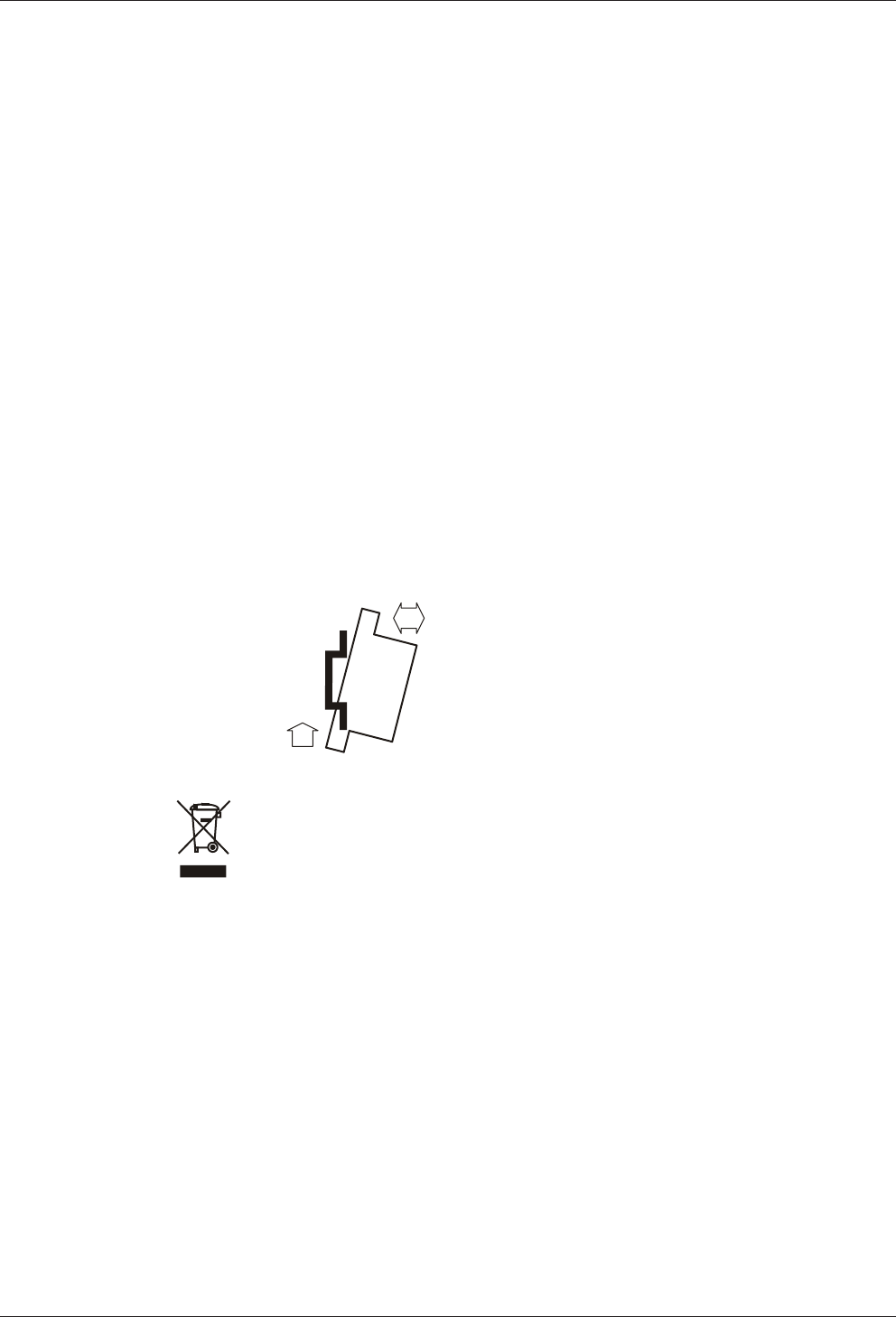
Disposal Technical Manual
98 04045708 - 04/2016 Kaba Remote Reader 91 25-AM (US/
CAN)
10 Disposal
This chapter provides important information on disposal.
10.1 Decommissioning
The following steps should be executed for the decommissioning of the device in an
access control system:
1. For online operation: Check configuration of the host system
2. Disconnect the device from the power supply
3. Disconnect RS-485 connection from the host system
10.2 Dismantling
üThe device has been decommissioned.
1. If available, unplug extension modules
2. Disconnect relay outputs from the device
3. Disconnect inputs from the device
4. Disconnect RS-232 interface and/or keypads, biometrics or system-dependent
functions from the device
5. Disconnect registration units from the device
6. Remove device from the rail
2
1
Click
Push
10.3 Disposal
This product meets the requirements of the WEEE Directive and, in accordance with
DIN standard EN 50419, is labeled with the WEEE crossed-out garbage can symbol.
The symbol indicates the separate disposal of electric and electronic equipment in
EU countries.
Do not dispose of the device with household waste under any circumstances.
Used devices contain valuable recyclable materials that should be recycled. Used de-
vices should therefore be disposed of via the collection system used in your country.
Disposal in Germany:
After use, Kaba GmbH undertakes to carry out the proper disposal of the supplied
goods in line with legal requirements (such as the ElektroG law in Germany). All costs
incurred for the transport of goods to the manufacturer's plant will be borne by the
owner of the used electronic equipment.
Disposal in Switzerland:
Send the device to an electronic equipment collection facility as per the VREG regula-
tion.
In the EU, electrical devices should be disposed of in accordance with national waste
disposal and environmental directives.
The erasure of personal data before disposal must be carried out self-dependent.

Technical Manual Disposal
9904045708 - 04/2016Kaba Remote Reader 91 25-AM (US/
CAN)
Dispose of packaging in an environmentally-friendly manner.
The packaging materials are recyclable. Please do not put the packaging in with
household waste, instead dispose of with waste for recycling.

Disposal Technical Manual
100 04045708 - 04/2016 Kaba Remote Reader 91 25-AM (US/
CAN)
Index
C
CE conformity ............................................................................. 22
Conformity................................................................................... 22
D
Designated use .......................................................................... 11
Disposal ........................................................................................ 98
Door contact ............................................................................... 52
Door frame contact .................................................................. 52
Door opener................................................................................ 52
E
Electromagnetic fields............................................................. 51
EMC directive.............................................................................. 22
ESD protective measures........................................................ 12
Extension modules ................................................................... 18
F
Factory reset................................................................................ 88
Firmware update....................................................................... 90
G
Grouped safety messages...................................................... 11
I
Identification plate ................................................................... 24
Installation cables ..................................................................... 52
L
LED Display............................................................................30, 93
LEGICOS update........................................................................ 90
Low voltage directive .............................................................. 22
O
Offline Operation ................................................................31, 32
Online operation .................................................................31, 32
P
Packaging..................................................................................... 96
Power supply line...................................................................... 53
Programming interface........................................................... 86
R
R&TTE directive ................................................................ 22
Return............................................................................................ 96
RoHS............................................................................................... 22
RS-485 bus termination .......................................................... 69
S
Safety ............................................................................................. 11
Safety messages ........................................................................ 11
Supplementary Documentation.............................................8
T
Troubleshooting........................................................................ 93