dresden elektronik ingenieurtechnik MEGA23M12 2.4GHz IEEE 802.15.4 compliant radio module User Manual 15 MEGA23M12 UserMan
dresden elektronik ingenieurtechnik gmbh 2.4GHz IEEE 802.15.4 compliant radio module 15 MEGA23M12 UserMan
Contents
- 1. 15_MEGA23M12_User _Manual
- 2. 15_MEGA23M12_UserMan
- 3. Users Manual
15_MEGA23M12_UserMan
![User Manual Version 1.0 2016-06-15 ConBee - USB Dongle www.dresden-elektronik.de Page 5 of 25 Abbreviations Abbreviation Description IEEE 802.15.4 Communication standard, applicable to low-rate Wireless Personal Area Networks (WPAN) CE Consumer Electronics ETSI European Telecommunications Standards Institute FCC Federal Communications Commission GPIO Generals Purpose Input Output JTAG Joint Test Action Group, digital interface for debugging of embedded devices, also known as IEEE 1149.1 standard interface MAC Medium (Media) Access Control MCU, µC Microcontroller Unit OS Operating System RF Radio Frequency RPi Raspberry Pi, a famous inexpensive single board computer in credit card size R&TTE Radio and Telecommunications Terminal Equipment (Directive of the European Union) U[S]ART Universal [Synchronous/]Asynchronous Receiver Transmitter ZigBee Low-cost, low-power wireless mesh network standard. The ZigBee Alliance is a group of companies that maintain and publish the ZigBee standard. ZHA ZigBee Home Automation profile ZLL ZigBee Light Link profile](https://usermanual.wiki/dresden-elektronik-ingenieurtechnik/MEGA23M12.15-MEGA23M12-UserMan/User-Guide-3049926-Page-5.png)
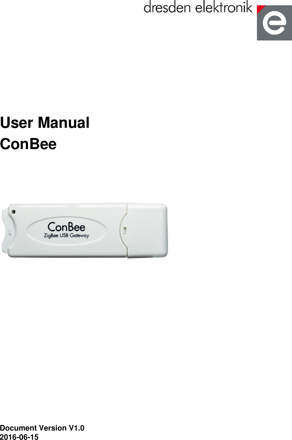
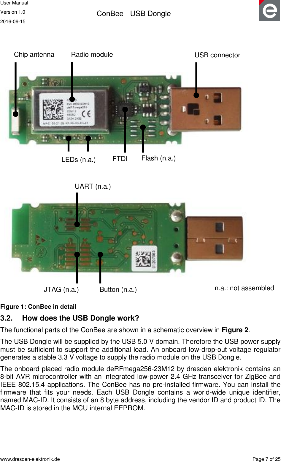
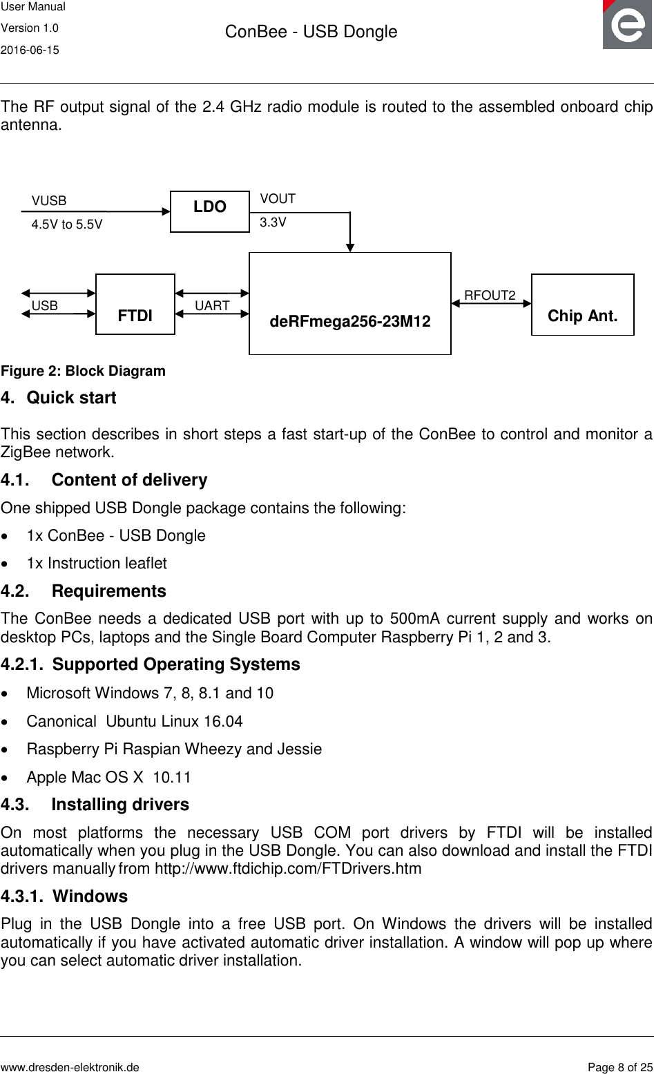
![User Manual Version 1.0 2016-06-15 ConBee - USB Dongle www.dresden-elektronik.de Page 6 of 25 1. Overview The ConBee is the platform independent USB Dongle that turns your host into a full functional wireless node which can be seamlessly integrated into ZigBee networks. This will enhance the application range of your host with monitoring and controlling ZigBee networks. ZigBee compatible devices are available from a lot of manufacturers. This USB Dongle contains a powerful radio module with integrated power amplifier and low noise amplifier. Together with the assembled onboard chip antenna which has been optimally tuned ensures a superior RF performance. The ConBee is shipped with a bootloader application for simple firmware uploads and updates. The ZigBee firmware is interfaced by a software called deCONZ which runs on Windows, Linux and Mac OS X and is responsible for ZigBee network control and monitoring. Basically, the USB Dongle is a reference design for the ZigBee radio module deRFmega256-23M12 by dresden elektronik. 2. Applications Mainly the ConBee is designed to handle ZigBee Light Link (ZLL) and ZigBee Home Automation (ZHA) applications in connection with the ZigBee firmware and software deCONZ. A more detailed description of the ZLL standard, the features, benefits and available certified products can be found on the official alliance website [1]. It is also possible to use a custom firmware for wireless applications. Follow the instructions in Section 5 and Section 10 for detailed instructions on software installation and customer modifications. Note: Please note that depending on the modifications the radio certification and compliance may become invalid. Please get in contact with us to advise you for a custom FCC certified and/or compliant design. 3. Features The ConBee contains the features listed below. Figure 1 illustrates the feature parts in a detailed view. 3.1. Short facts Slim size: 70.7 x 23.0 x 8.3 mm Supply voltage: USB powered 5.0V / DC Onboard 2.4 GHz ZigBee radio module „deRFmega256-23M12‟ Application interfaces: USB](https://usermanual.wiki/dresden-elektronik-ingenieurtechnik/MEGA23M12.15-MEGA23M12-UserMan/User-Guide-3049926-Page-6.png)
![User Manual Version 1.0 2016-06-15 ConBee - USB Dongle www.dresden-elektronik.de Page 9 of 25 4.3.2. Linux No further driver installation is needed. All common Linux distributions include the necessary COM port drivers. 4.3.3. Mac OS X No further driver installation is needed. Mac OS X includes the necessary COM port drivers. 4.4. Using the USB Dongle with deCONZ application The deCONZ1 application allows the configuration, operation, monitoring and maintenance of ZigBee networks. 4.4.1. Windows 1. Download and install the deCONZ software from: https://www.dresden-elektronik.de/funktechnik/products/software/pc/deconz/ Important Note: The next step will bring up a windows firewall warning. This happens because deCONZ runs a webserver to provide the WebApp and is using a discovery mechanism via Internet so that your devices can find the WebApp. For proper operation it‟s required to confirm the firewall exception. 2. Start the deCONZ application from the start menu. 3. The application automatically connects to the USB Dongle and a blue coordinator node with address 0x0000 appears. 4. In a browser navigate to http://www.dresden-elektronik.de/discover/ 5. Login as user: delight and password: delight For further instructions on the WebApp refer to the Quick Start Guide [3]. 4.4.2. Raspbian Linux 4.4.2.1. Required software packages 1. Download and install Qt 4.8 $ sudo apt-get install libqt4-core 4.4.2.2. Download and install deCONZ 1. Download deCONZ software package: $ wget http://www.dresden-elektronik.de/rpi/deconz/stable/deconz-latest.deb 2. Install deCONZ software package: $ sudo dpkg -i deconz-latest.deb 4.4.2.3. Start and run the application 1. If not already running start the desktop environment 1 See https://www.dresden-elektronik.de/funktechnik/products/software/pc-software/deconz/?L=1](https://usermanual.wiki/dresden-elektronik-ingenieurtechnik/MEGA23M12.15-MEGA23M12-UserMan/User-Guide-3049926-Page-9.png)
![User Manual Version 1.0 2016-06-15 ConBee - USB Dongle www.dresden-elektronik.de Page 10 of 25 $ startx 2. Start the deCONZ application via start menu Menu / Programming /deCONZ 3. In a browser navigate to http://www.dresden-elektronik.de/discover/ 4. Login as user: delight and password: delight For further instructions on the WebApp refer to the Quick Start Guide [3]. 4.4.2.4. Execute the application at start-up 1. Create the folder “autostart”: $ mkdir -p /home/pi/.config/autostart/ 2. Create and edit the file “deCONZ.desktop”: $ nano /home/pi/.config/autostart/deCONZ.desktop 3. Insert the following lines and save the file: [Desktop Entry] Type=Application Name=deCONZ Exec=deCONZ-autostart.sh StartupNotify=false Now, the application will run automatically after start-up of the Raspberry Pi. 4.4.3. Ubuntu Linux 1. Download the deCONZ (Ubuntu Linux) software from: https://www.dresden-elektronik.de/funktechnik/products/software/pc/deconz 2. In the file manager right click on the downloaded .deb file and chose “Open With / Ubuntu Software Center”. In the software center click on the install button. 3. Start the deCONZ application from the applications menu. 4. The application automatically connects to the USB Dongle and a blue coordinator node with address 0x0000 appears. 5. In a browser navigate to http://www.dresden-elektronik.de/discover/ 6. Login as user: delight and password: delight For further instructions on the WebApp refer to the Quick Start Guide [3]. 4.4.4. Mac OS X 1. Download the deCONZ (OS X) software from: https://www.dresden-elektronik.de/funktechnik/products/software/pc/deconz 2. Unzip the package and drag the deCONZ.app file to applications folder. 3. For the first start you need to right click the deCONZ application in Finder and chose open. After that deCONZ can be started from Launchpad.](https://usermanual.wiki/dresden-elektronik-ingenieurtechnik/MEGA23M12.15-MEGA23M12-UserMan/User-Guide-3049926-Page-10.png)
![User Manual Version 1.0 2016-06-15 ConBee - USB Dongle www.dresden-elektronik.de Page 11 of 25 4. The application automatically connects to the USB Dongle and a blue coordinator node with address 0x0000 appears. 5. In a browser navigate to http://www.dresden-elektronik.de/discover/ 6. Login as user: delight, password: delight For further instructions on the WebApp refer to the Quick Start Guide [3]. 5. Installing individual firmware with GCFFlasher GCFFlasher is a command line tool which can be used to update the USB Dongle without additional programming hardware. It is also used by deCONZ to update the ZigBee firmware. The GCFFlasher communicates with the USB Dongle bootloader via COM port interface. Note 1: GCFFlasher accepts firmware files in binary file format (.bin) and in dresden elektronik‟s proprietary GCF file format. There is no EEPROM programming support within GCFFlasher. EEPROM programming must be done within your application code. Please note that modifying the EEPROM may cause irreversibly damage to your USB Dongle. Use with care. GCFFlasher also provides the option „-r‟ to power cycle the target device. Note 2: It is not possible to perform the update while running the deCONZ application. Therefore it is necessary to close the deCONZ application before updating the firmware with GCFFlasher. Note 3: For help on the GCFFlasher options run: GCFFlasher -h 5.1. Windows 1. Download GCFFlasher (Windows) from: https://www.dresden-elektronik.de/funktechnik/service/downloads/software 2. Unzip the package and double click the GCFFlasherCommandline.bat file. A command prompt will open and output a list of all connected device(s). 3. Put the firmware file in the same folder as GCFFlasher.exe 4. To upload the firmware, invoke GCFFlasher from the command prompt as follows: GCFFlasher –d <device> -f <YourApplication.bin[.GCF]> For example: GCFFlasher –d 0 –f deCONZ_0x26050500.bin.GCF Note: You can list the devices with: GCFFlasher –l 5.2. Raspbian Linux 1. Download GCFFlasher $ wget http://www.dresden-elektronik.de/rpi/gcfflasher/gcfflasher-latest.deb 2. Install GCFFlasher $ sudo dpkg -i gcfflasher-latest.deb 3. To upload the firmware, invoke GCFFlasher (superuser rights required) as follows:](https://usermanual.wiki/dresden-elektronik-ingenieurtechnik/MEGA23M12.15-MEGA23M12-UserMan/User-Guide-3049926-Page-11.png)
![User Manual Version 1.0 2016-06-15 ConBee - USB Dongle www.dresden-elektronik.de Page 12 of 25 $ sudo GCFFlasher –d <device> -f <YourApplication.bin[.GCF]> For example: $ sudo GCFFlasher –d 0 –f deCONZ_0x26050500.bin.GCF Note: You can list all devices with: $ sudo GCFFlasher –l 5.3. Ubuntu Linux 1. Download GCFFlasher (Ubuntu Linux) from: https://www.dresden-elektronik.de/funktechnik/service/downloads/software 2. In the file manager right click on the downloaded .deb file and chose “Open With / Ubuntu Software Center”. In the software center click on the install button. 3. To upload the firmware, invoke GCFFlasher (superuser rights required) as follows: $ sudo GCFFlasher –d <device> -f <YourApplication.bin[.GCF]> For example: $ sudo GCFFlasher –d 0 –f deCONZ_0x26050500.bin.GCF Note: You can list all devices with: $ sudo GCFFlasher –l 5.4. Mac OS X 1. Download GCFFlasher (OS X) from: https://www.dresden-elektronik.de/funktechnik/service/downloads/software 2. In Finder unzip the package by double click on it. 3. Put the firmware file in the unzipped folder 4. Open a terminal and cd into the GCFFlasher folder 5. To upload the firmware, invoke GCFFlasher from the command line as follows: $ sudo GCFFlasher –d <device> -f <YourApplication.bin[.GCF]> For example: $ sudo GCFFlasher –d 0 –f deCONZ_0x26050500.bin.GCF Note: You can list all devices with: $ sudo GCFFlasher –l 5.5. Notes on custom firmware When using the JTAG interface, do not modify sensitive EEPROM areas like Bootloader control section, ZigBee firmware settings, NV-section containing i.e. MAC address, unless you are absolutely sure what you are doing. Please also note that dresden elektronik will neither provide firmware images of the bootloader nor support restoring the bootloader or EEPROM once overwritten. 5.6. Example with BitCatcher BitCatcher is a software tool for analyzing wireless transmissions in ZigBee based networks and allows the monitoring of complex network structures as well as observe data flows and runtime performance in detail without additional effort.](https://usermanual.wiki/dresden-elektronik-ingenieurtechnik/MEGA23M12.15-MEGA23M12-UserMan/User-Guide-3049926-Page-12.png)
![User Manual Version 1.0 2016-06-15 ConBee - USB Dongle www.dresden-elektronik.de Page 13 of 25 5.6.1. Software 1. Download and install the Luxoft BitCatcher ZigBee Network Analyzer from: http://www.luxoft.com/embedded-systems-development/bitcatcher 5.6.2. Firmware 1. Download the BitCatcher firmware for ConBee from: https://www.dresden-elektronik.de/funktechnik/service/downloads/software/ 2. Execute the steps of section 5.1, 5.2 and 5.3 depending on your operating system. 5.7. EEPROM layout The radio module contained on the ConBee uses the following EEPROM sections. If developing custom firmware, please do not modify the sections already used. Table 1: EEPROM sections EEPROM sections address range content / remark 0x0000 ... 0x00FF Bootloader specific 0x0100 ... 0x1EFF user available 0x1F00 ... 0x1FDF ZigBee firmware specific 0x1FE0 ... 0x1FFF NV-section 5.8. Fuse setting The table below shows the recommended fuse byte settings for the ConBee which the board also comes with in factory new condition. Please refer to the radio module user manual [4] for their description and alternative configurations. Table 2: Fuse settings Fuse bytes Setting Description EXTENDED 0xF8 Extended fuse byte HIGH 0x90 Fuse high byte LOW 0xCE Fuse low byte 6. Technical data The USB Dongle contains the 2.4 GHz IEEE 802.15.4 radio module „deRFmega256-23M12‟ by dresden elektronik. A detailed description of the module‟s characteristics and properties can be found in the radio module user manual [4].](https://usermanual.wiki/dresden-elektronik-ingenieurtechnik/MEGA23M12.15-MEGA23M12-UserMan/User-Guide-3049926-Page-13.png)
![User Manual Version 1.0 2016-06-15 ConBee - USB Dongle www.dresden-elektronik.de Page 16 of 25 6.1. Output power and channel settings The ConBee is able to provide an output power greater than 10 dBm. Table 9 defines the power settings of the TX_PWR register [4], which must be set to fulfill all national requirements of Europe (EN 300 328) and the United States (CFR 47 Ch. I FCC Part 15). Note: Channel 26 must be deactivated for using the USB Dongle in the United States to fulfill the band edge requirements of FCC Part 15 Subpart C § 15.247. Table 9: Output power settings Device ConBee Region ETSI (EU) FCC (US) Channel TX_PWR TX_PWR 11 0xF 0xE 12 0xF 0xE 13 0xF 0xE 14 0xF 0xE 15 0xF 0xE 16 0xF 0xE 17 0xF 0xE 18 0xF 0xE 19 0xF 0xE 20 0xF 0xE 21 0xF 0xE 22 0xF 0xE 23 0xF 0xE 24 0xF 0xE 25 0xF 0xF 26 0xF Not used](https://usermanual.wiki/dresden-elektronik-ingenieurtechnik/MEGA23M12.15-MEGA23M12-UserMan/User-Guide-3049926-Page-16.png)
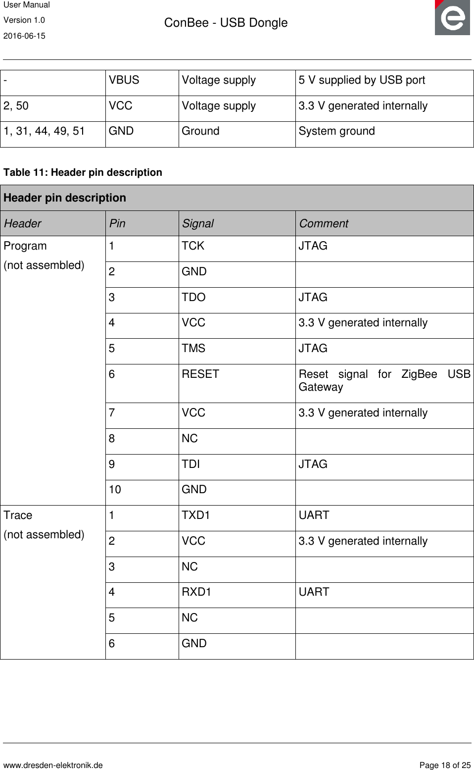
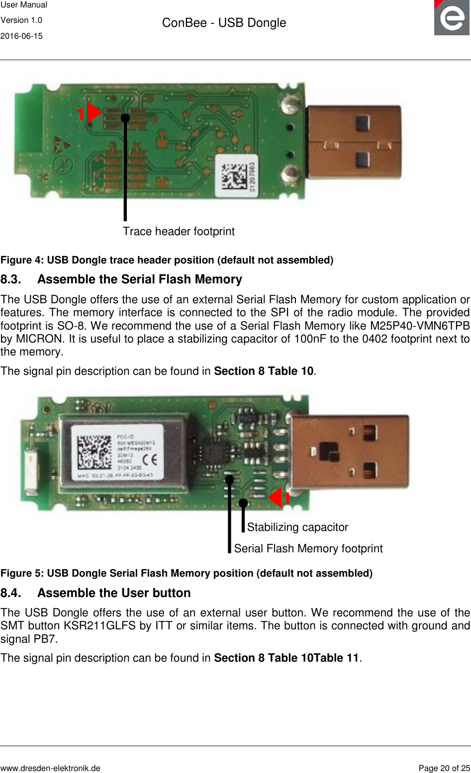
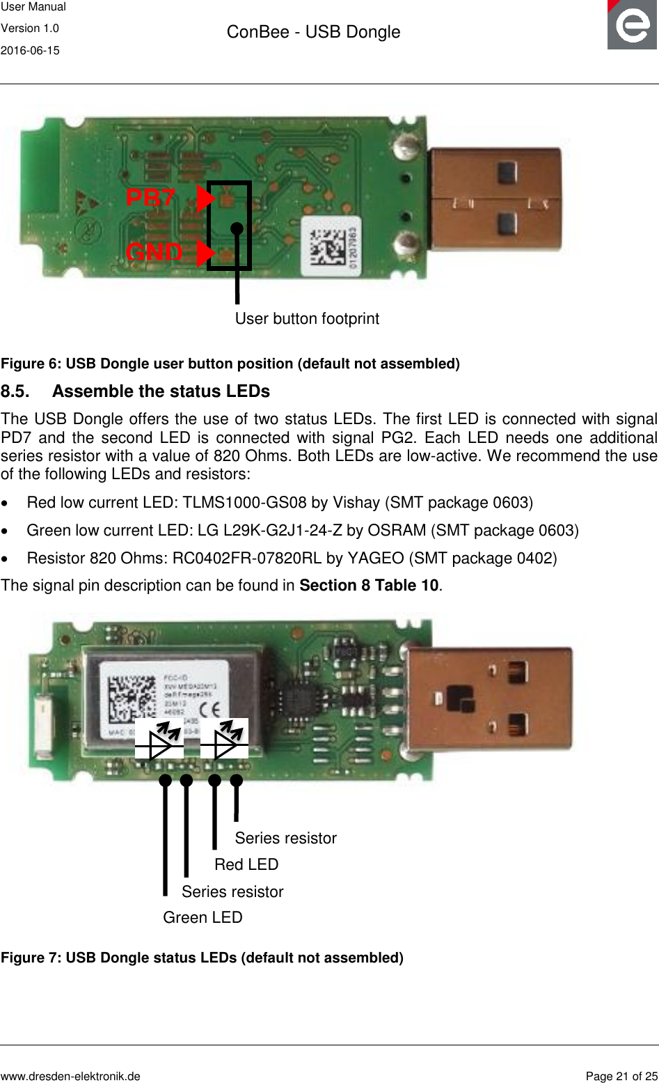
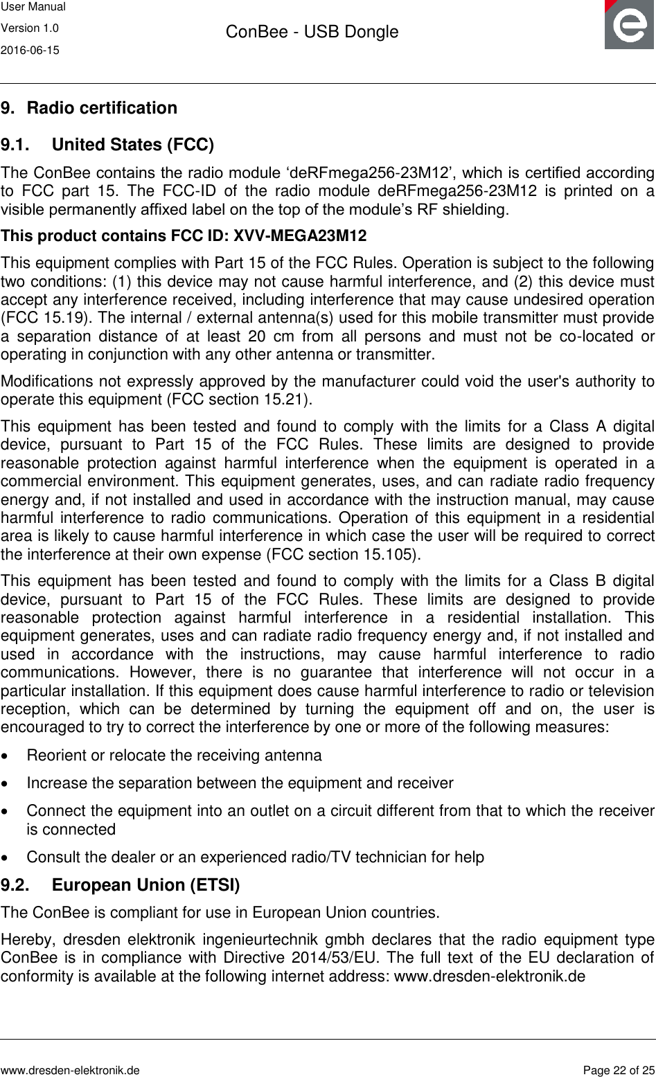
![User Manual Version 1.0 2016-06-15 ConBee - USB Dongle www.dresden-elektronik.de Page 19 of 25 8. Hardware modifications for development Besides the factory-default USB Dongle configuration it is also possible to modify the hardware to enhance its functionality. 8.1. Assemble the program header The program header provides the microcontroller programming interface of the radio module. Assemble a 50 mil 10-pin SMT header on the bottom side. We recommend the use of the header FTSH-105-04-LM-DV-P by SAMTEC or a similar item. The header pin description can be found in Section 8 Table 11 . A detailed description of suitable programmers and related software tools are listed in [5]. Figure 3: USB Dongle program header position (default not assembled) Note: Improper handling in respect of erasing or overwriting the MCU internal flash or EEPROM completely or in parts may result in an unusable USB Dongle unit. Modification of the pre-allocated EEPROM memory sections or removal of the pre-installed bootloader will irreversibly preclude restoring, booting or upgrading the shipping firmware at all. dresden elektronik will not support such modifications (see Section 5.3 for details). 8.2. Assemble the trace header The trace header provides the microcontroller UART interface of the radio module. Assemble a 50 mil 6-pin SMT header on the bottom side. We recommend the use of the header FTSH-103-01-F-DV by SAMTEC or a similar item. The header pin description can be found in Section 8 Table 11. Program header footprint 1](https://usermanual.wiki/dresden-elektronik-ingenieurtechnik/MEGA23M12.15-MEGA23M12-UserMan/User-Guide-3049926-Page-19.png)
![User Manual Version 1.0 2016-06-15 ConBee - USB Dongle www.dresden-elektronik.de Page 24 of 25 12. References [1] ZigBee Light Link, URL: http://www.zigbee.org/zigbee-for-developers/applicationstandards/zigbee-light-link/ [2] User Manual deCONZ; URL: https://www.dresden-elektronik.de/funktechnik/service/downloads/documentation/ [3] Quick Start Guide Wireless Light Control, URL: https://www.dresden-elektronik.de/funktechnik/service/downloads/documentation/ [4] User Manual deRFmega256 radio modules; URL: https://www.dresden-elektronik.de/funktechnik/service/downloads/documentation/ [5] Software Programming User Manual; URL: https://www.dresden-elektronik.de/funktechnik/service/downloads/documentation/](https://usermanual.wiki/dresden-elektronik-ingenieurtechnik/MEGA23M12.15-MEGA23M12-UserMan/User-Guide-3049926-Page-24.png)