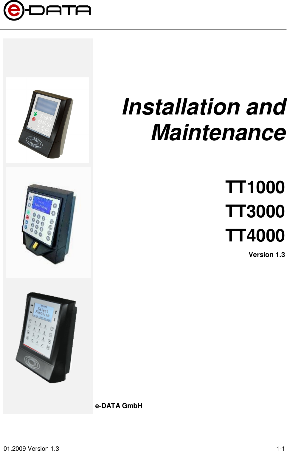
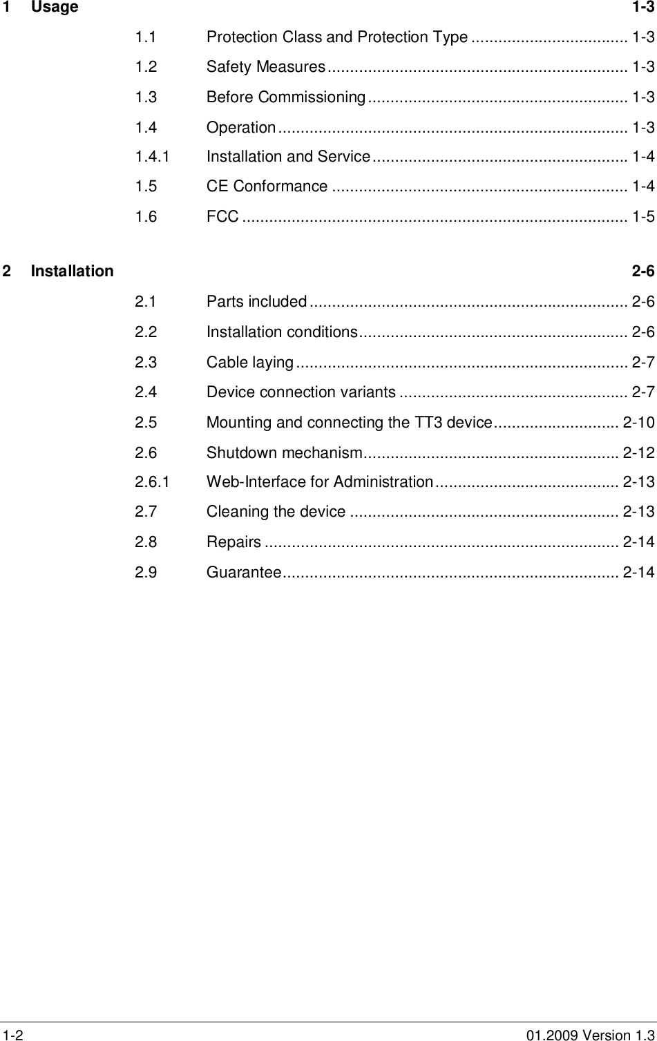
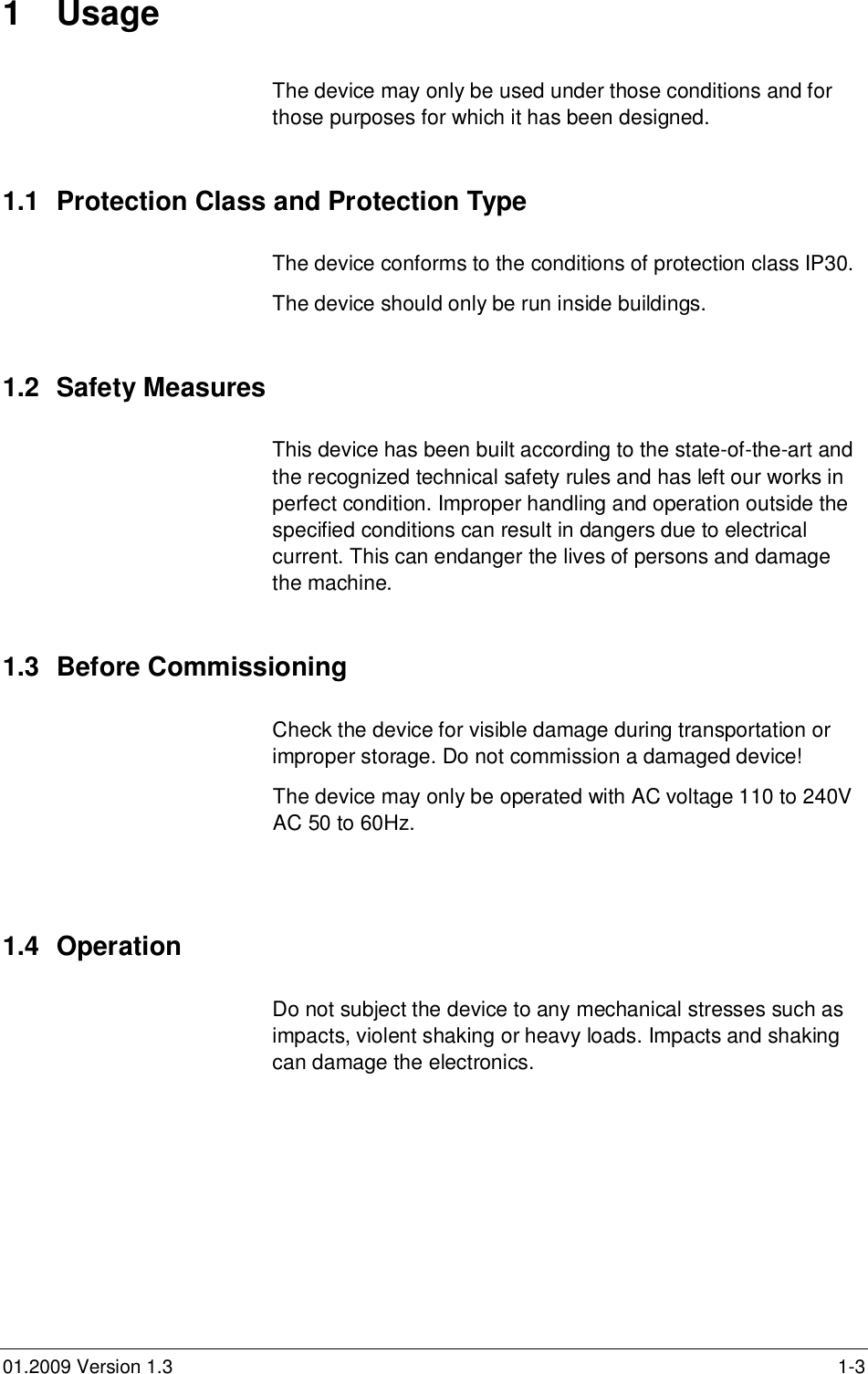
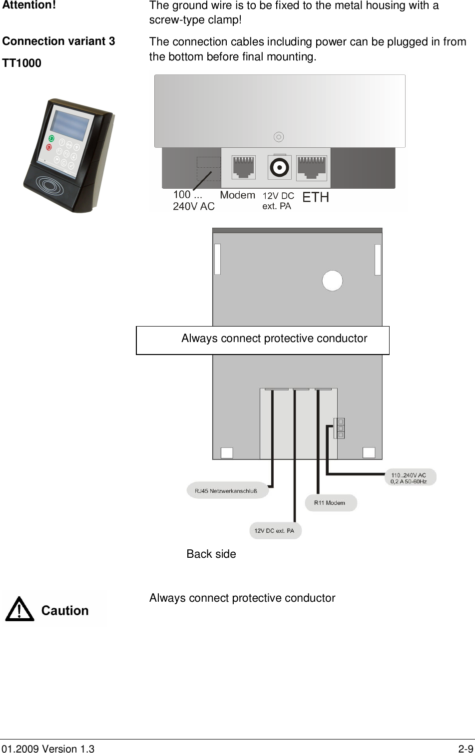
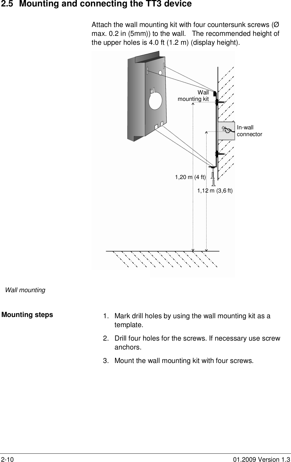
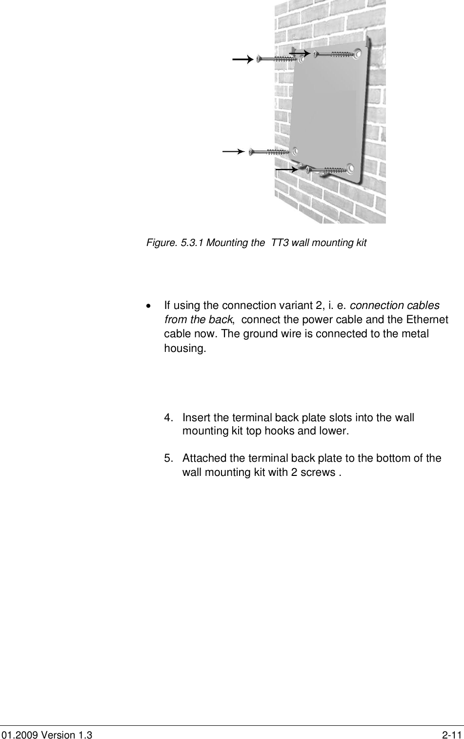
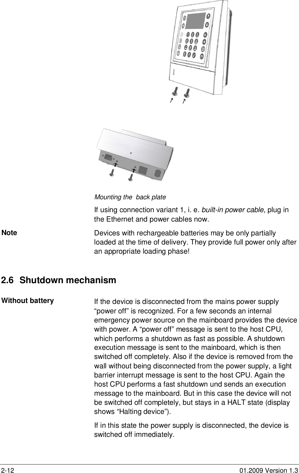
e DATA TT1000 Badge Reader User Manual installation

e-DATA GmbH Badge Reader installation

Contents

installation user manual

01.2009 Version 1.3 1-1Installation andMaintenanceTT1000TT3000TT4000Version 1.3e-DATA GmbH
1-2 01.2009 Version 1.31Usage 1-31.1 Protection Class and Protection Type ................................... 1-31.2 Safety Measures................................................................... 1-31.3 Before Commissioning.......................................................... 1-31.4 Operation.............................................................................. 1-31.4.1 Installation and Service......................................................... 1-41.5 CE Conformance .................................................................. 1-41.6 FCC ...................................................................................... 1-52Installation 2-62.1 Parts included....................................................................... 2-62.2 Installation conditions............................................................ 2-62.3 Cable laying.......................................................................... 2-72.4 Device connection variants ................................................... 2-72.5 Mounting and connecting the TT3 device............................ 2-102.6 Shutdown mechanism......................................................... 2-122.6.1 Web-Interface for Administration......................................... 2-132.7 Cleaning the device ............................................................ 2-132.8 Repairs ............................................................................... 2-142.9 Guarantee........................................................................... 2-14
01.2009 Version 1.3 1-31 UsageThe device may only be used under those conditions and forthose purposes for which it has been designed.1.1  Protection Class and Protection TypeThe device conforms to the conditions of protection class IP30.The device should only be run inside buildings.1.2  Safety MeasuresThis device has been built according to the state-of-the-art andthe recognized technical safety rules and has left our works inperfect condition. Improper handling and operation outside thespecified conditions can result in dangers due to electricalcurrent. This can endanger the lives of persons and damagethe machine.1.3  Before CommissioningCheck the device for visible damage during transportation orimproper storage. Do not commission a damaged device!The device may only be operated with AC voltage 110 to 240VAC 50 to 60Hz.1.4 OperationDo not subject the device to any mechanical stresses such asimpacts, violent shaking or heavy loads. Impacts and shakingcan damage the electronics.
1-4 01.2009 Version 1.31.4.1  Installation and ServiceThe device should only be opened by suitably trained technicalpersonnel.Before opening disconnect the device from the power source.You should carry out repairs only in consultation withe-DATA GmbH1.5  CE ConformanceSafety requirements This device is manufactured according to the safetyrequirements of EN 60950.Interference resistance This device complies to the interference resistance criteriaaccording to EN 55024Emitted interference This terminal complies to the emitted interference criteriaaccording to:EN 55022EN 61000Emitted interferenceTT1000EN 55022EN 61000CSA 60950 und FCC
01.2009 Version 1.3 1-51.6 FCCThis equipment complies with Part 15 of the FCC rules. Any changes or modifications notexpressly approved by the Manufacturer could void the user's authority to operate theequipment. This device complies with Part 15 of the FCC rules subject tothefollowing two conditions:1.  This device may not cause harmful interference2.  This device must accept all interference received, including interference that maycause undesired operation.NOTE:This equipment has been tested and found to comply with the limits for a Class A digitaldevice, pursuant to part 15 of the FCC Rules. These limits are designed to providereasonable protection against harmful interference when the equipment is operatedin a commercial environment.This equipment generates, uses, and can radiate radio frequency energy and, if not installedand used in accordance with the instruction manual, may cause harmful interference to radiocommunications. Operation of this equipment in a residential area is likely to cause harmfulinterference in which case the user will be required to correct the interference at his ownexpense.
2-6 01.2009 Version 1.32 InstallationDanger of current shocks!The device should only be opened by suitably trained technicalpersonnel.2.1  Parts included1 device for Time & Attendance1 wall mounting kit2.2  Installation conditionsSurface wall installation with hidden screws. The cables arefed on the back of the device under the plaster or as analternative from the bottom of the device.Data lines to the higher or lower-level device are providedby the customer.If using the connection variant 2, i.e.connection cables fromthe back, please ensure, that the in-wall connector islocated at the right position. See figure 5.3The power supply is provided by the customer.Security advice To limit the input voltage of the device to overvoltagecategory II the customer provides an appropriateovervoltage protection unit!Also an appropriate, easily accessible separator for thepower circuit is provided by the customer.The power supply provided by the customer must use solidconductors or a build-in power cable and a power outlet!Possibly national regulations apply.Network connections are only allowed within the same building!
01.2009 Version 1.3 2-7Before mounting the device to the wall, please check thefollowing pre-conditions:Clearance Enough clearance must be available for mounting the device(see casing dimensions in fig. 4.1).Make sure enough clearance is available for the cables thatmight be fed from the back.2.3  Cable layingGeneral hints Do not lay the data lines in parallel with cables that carry highvoltage. If this cannot be avoided, lay the lines in closed steeltubes and keep a distance of 3 ft. for the protection fromelectromagnetic influences.2.4  Device connection variantsConnection variant 1TT3000 und TT4000For this variant a fix built-in power cable to be connected to awall outlet is used. The connection cables for the device can beplugged in at the bottom side of the device.The connectors COM1 and COM3 can only be reached frombeneath.Figure 5.1 Connections TT3 bottom side   COM1/         COM3      ETH   Console        ISDN/                        ModemBuilt-inpower cablelength 1,50 m(5 ft)100 ... 240V AC
2-8 01.2009 Version 1.3Connection variant 2TT3000 und TT4000For this variant there is no preinstalled power cable. Theconnection cables including power can be plugged in from theback through a hole in the back plate.The IO clamp can only be reached from the back.sConnections TT3000 / 4000 back side                                       ground wire    pluggable clamp                  L               USB                     power                 N                                                                      ETH pluggable clamp         IO                     Power cable                     LAN Ethernet cableground wire
01.2009 Version 1.3 2-9Attention! The ground wire is to be fixed to the metal housing with ascrew-type clamp!Connection variant 3TT1000The connection cables including power can be plugged in fromthe bottom before final mounting.Back sideAlways connect protective conductorAlways connect protective conductor
2-10 01.2009 Version 1.32.5  Mounting and connecting the TT3 deviceAttach the wall mounting kit with four countersunk screws (Ømax. 0.2 in (5mm)) to the wall.   The recommended height ofthe upper holes is 4.0 ft (1.2 m) (display height).  Wall mountingMounting steps 1.  Mark drill holes by using the wall mounting kit as atemplate.2.  Drill four holes for the screws. If necessary use screwanchors.3.  Mount the wall mounting kit with four screws.1,20 m (4 ft)            1,12 m (3,6 ft)Wallmounting kitIn-wallconnector
01.2009 Version 1.3 2-11Figure. 5.3.1 Mounting the  TT3 wall mounting kit  If using the connection variant 2, i. e. connection cablesfrom the back, connect the power cable and the Ethernetcable now. The ground wire is connected to the metalhousing.4.  Insert the terminal back plate slots into the wallmounting kit top hooks and lower.5.  Attached the terminal back plate to the bottom of thewall mounting kit with 2 screws .
2-12 01.2009 Version 1.3Mounting the  back plateIf using connection variant 1, i. e. built-in power cable, plug inthe Ethernet and power cables now.Note Devices with rechargeable batteries may be only partiallyloaded at the time of delivery. They provide full power only afteran appropriate loading phase!2.6  Shutdown mechanismWithout battery If the device is disconnected from the mains power supply“power off” is recognized. For a few seconds an internalemergency power source on the mainboard provides the devicewith power. A “power off” message is sent to the host CPU,which performs a shutdown as fast as possible. A shutdownexecution message is sent to the mainboard, which is thenswitched off completely. Also if the device is removed from thewall without being disconnected from the power supply, a lightbarrier interrupt message is sent to the host CPU. Again thehost CPU performs a fast shutdown und sends an executionmessage to the mainboard. But in this case the device will notbe switched off completely, but stays in a HALT state (displayshows “Halting device”).If in this state the power supply is disconnected, the device isswitched off immediately.
01.2009 Version 1.3 2-13With rechargeable battery If mains “power off” is recognized, the device switches tobattery operation. The new state is sent to the host CPU and (ifthe battery is loaded) nothing else happens.If in this state the device is removed from the wall, a light barrierinterrupt message is sent to the host CPU. The host CPUperforms a fast shutdown und sends an execution message tothe mainboard. The mainboard turns off the battery, thusswitching off the device.Also if the device is removed from the wall without beingdisconnected from the mains power supply, a light barrierinterrupt message is sent to the host CPU. Again the host CPUperforms a fast shutdown und sends an execution message tothe mainboard. But in this case the device will not be switchedoff completely, but stays in a HALT state (display shows“Halting device”).If in this state the mains power supply is disconnected, thedevice is switched off immediately (without using the battery).2.6.1  Web-Interface for AdministrationFor accessing the webinterface of the terminal, please pointyour browser to thehttp://terminal-ip-adress e.g http://192.168.0.100 of the terminal.Choose your language and enter with the password “admin”Danger of current shocks!Disconnect the device from the power source before opening!2.7  Cleaning the device
2-14 01.2009 Version 1.3Organic solvents and scouring agents can damage the device.Clean the device with a moist, non-fluffing cloth.2.8 RepairsRepairs may only be carried out by permission ofTimelink International.Repairs must be carried out professionally. Only originalcomponents may be used as spare parts.2.9 GuaranteeThe elements of guarantee are established by legal regulation.e-DATA GmbHMollenbachstrasse 19D-71229 LeonbergGermanyPhone 0049(0) 71 52 93979 -0Fax 0049(0) 71 52 93079 -50Installation and Maintenance TT DevicesVersion 1.3Copyright 2009 e-DATA GmbHThis manual is protected. Reproduction or translation of themanual or its transmission on other electronic media, even inextract form, is only allowed with the express written permissionof e-DATA GmbHe-DATA GmbH reserves the right to make changes to the usermanual without prior notice.e-DATA GmbH does not accept any liability whatever for directand indirect damage, especially loss of data, that result from theusage of the device, the software or the manual!

Navigation menu