ePrep EPREP-01 ePrep Sample Preparation Workstation User Manual PowerPoint Presentation

ePrep Pty Ltd ePrep Sample Preparation Workstation PowerPoint Presentation

Contents

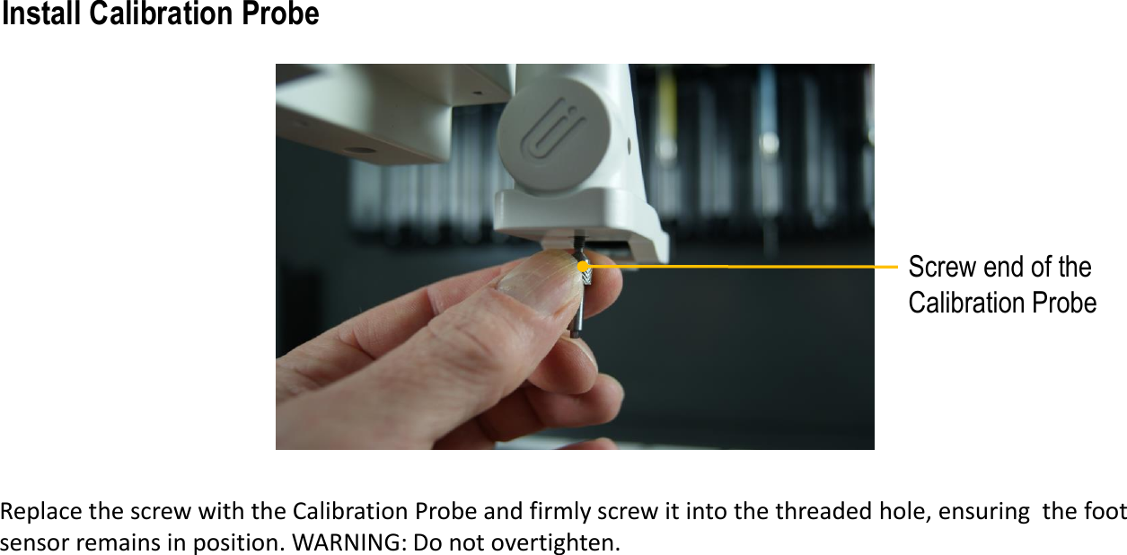
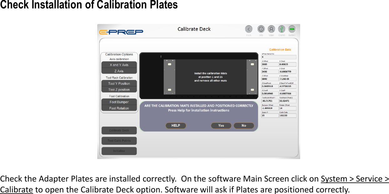
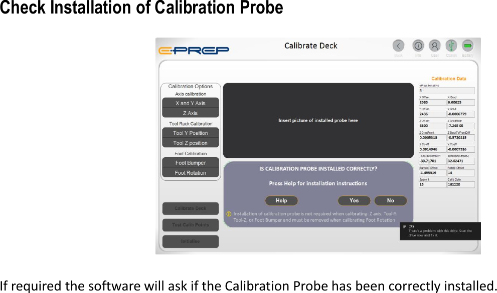
Tablet installation procedure

Place ePrep on a clean flat surface with no obstruction to the axis movement. Adjust ePrep feet to level instrument if required. ePrep Location Pub No. 99-10010-01
Power up the Tablet Computer and open the ePrep software via the desktop ePrepApp icon shown above. Further installation instructions can be found on the Tablet.Connect USB Cable and Open Tablet Software
Go to System>Quick Start for further setup instructions.ePrep Software Main Menu
IMPORTANT SAFETY WARNINGSDo not enter the instrument work space or place any part of your body near moving axes during operation.If the equipment is used in a manner not specified by the manufacturer, the protection provided by the equipment may be impaired. Good Laboratory Practice (GLP) should be followed when using the ePrep.  Refer: 21CFR58, 21CFR58, Directive 2004/9/EC and specific product GLP DirectivesePrep is fitted with an Emergency Stop Button found at the front right side of the instrument. Pressing the button will cut off all power to the instrument. To reinstate power, rotate the emergency button 90°clockwise.Only approved accessories and consumables can be used with the instrument. Eprep assumes no liability for the customer’s failure to comply with these requirements.
Drip Tray PositionInstall the Drip Tray below the deck area. The Tray is located in the front panel (first removed panel) of theePrep box.Install Drip Tray
Park StationBefore powering up the ePrep, manually move axis so XCHANGE change coupling is sitting on the Park Station.Manually Park the SystemManually move the XCHANGE axis onto the Park Station
Electrical Connection from ePrepUnderside of  Wash Station Deck Plate showing pumpsWash Station Electrical ConnectionEnsure ePrep power is switched off. Before installing the Wash Station deck plate, connect Pumps to ePrep via the electrical connection shown. Electrical Connection from Wash Station
Locking Screw Calibration Probe Storage PositionInstall the Wash Station Deck PlateInstall the Wash Station deck plate and lock it down using in installation screw.Location pin
Waste (Out) ConnectorWash Solution (≥600mL)Wash (In) Connector Wash Station Liquid ConnectionsInstall tubing to the Wash (IN) and Wash (OUT). Connect Wash (IN) to a receptacle bottle with at least 600mLof wash solution and wash (OUT) to a waste receptacle bottle.
Locking ScrewRear Right Deck PlateInstall Rear-Right PlateLocate and lock the Rear Right deck plate to the ePrep frame using the supplied installation screws.Location Pin
Tablet USB Cable ConnectionPower SwitchPower Pack Connection Slide Lock on Power Pack ConnectionConnect the Power Pack to ePrep and the mains power using a Country Specific IEC C13 cable (NOT SUPPLIED). Connect Tablet to ePrep with the supplied USB cable. Switch ePrep on. When the Tablet has established USB connection with ePrep the         icon will appear at the top right of the tablet screen. Cable Connection
Emergency Stop Button Ensure the Emergency Stop button is released by turning it 90° in the direction of the arrow. Note: press to engage (switches power OFF to ePrep) and rotate to release allows ePrep to be powered by the Power Switch.  Emergency Stop Button
Status Indicator Lights NO LIGHT  No power to the instrument  ORANGE Workflow  paused by user with the option to abort or continue.SOLID BLUE  ePrep ready for operation  RED Bumper  or instrument error. Check for obstructions to the rotating foot. Typically, items placed on the deck or different height vial in a rack. Faults with instrument hardware, see trouble shooting information. GREEN Workflow running and will remain green until completion or interruption of workflowFLASHBLUE Workflow completed successfullyFLASH PURPLE Workflow aborted by user Mains power disconnected and ePrep running on battery power. Battery life approximately 20 min.FLASH RED Workflow  aborted by system or Failure to detect racks or Failure to detect tubes.
Adapter Plates in Position 1 and 15Install supplied Adapter Plates in deck positions 1 and 15. Remove all other Adapter Plates from the deck.Install Vial Adapter Plates for Calibration
Screw Thread EndHex End Locate the Calibration Probe found  in the ePrep Accessories Box.Calibration Probe
Use the Hex end of the tool to undo the Sensor Retaining Screw at the base of the ePrep Rotating Foot. Hold the Bumper so that it does not fall off when the screw is removed. Hex end of the Calibration ProbeSensor retaining screwRemove the Sensor Retaining Screw
Screw end of the Calibration ProbeReplace the screw with the Calibration Probe and firmly screw it into the threaded hole, ensuring  the foot sensor remains in position. WARNING: Do not overtighten.Install Calibration Probe
Check the Adapter Plates are installed correctly. On the software Main Screen click on System > Service > Calibrate to open the Calibrate Deck option. Software will ask if Plates are positioned correctly. Check Installation of Calibration Plates
If required the software will ask if the Calibration Probe has been correctly installed.Check Installation of Calibration Probe
If Adapter Plates and Probe are installed, the following calibration options are available: X-Axis, Y-Axis, Z-Axis, Tool-Y, Tool-Z, Foot Sensor, Foot Rotation Note: user will be prompted to remove the calibration probe for foot rotation *. Calibration Data panel records and displays the calibration data used to calculate operational parameters. Calibration points are saved on the instrument firmware for real time calculation of positional data.Calibrate Deck: starts or stops (Aborts) the calibration. If required, a system initialisation will be performed.Test Calibrate Points button can be used to test the X, Y and Z calibration at four points on the deck. If required user will be prompted to remove the probe during the procedure.Deck Calibration
On initial installation and commissioning, all calibration options should be selected. Note: the software does allow for selective “optional” calibration depending on installation of Probe and Adapter Plates. Select ALL Calibration OptionsCalibration Options
Click on “Calibrate Deck”. ePrep will move the Calibration Probe to allocated positions on the deck and tool rack to record instrument calibration data. Full calibration takes around 10 minutes.Trigger Calibrate DeckCalibrate Deck Button
When complete the calibration dialogue will display "Calibration updated successfully". Calibration data is automatically written to the instrument EEPROM to be used during operation.Calibration Completion and Data Write
Remove the Probe and replace the Holding ScrewWhen prompted, remove the Calibration Probe and replace the Holding Screw before proceeding. Store the Calibration Probe in the threaded hole next to the Wash Station.Remove Calibration Probe
Wash StationCalibration probe storage positionScrew the Calibration Probe into its deck position next to the Wash Station for storage. Store Calibration Probe
Correct Orientation of Syringe on Cassette RackRFID TagMagnet for tool location identificationePrep Syringes and tools are fitted with RFID identification collars. Place the tool in the cassettes in the correct orientation (as shown) with the plunger fully down and the Tool Retainer Clip covering the plunger button.Installing Syringes and Tools
Large PinsRack Position No. Vial PositionsPlate Position IndicatorSmall PinsVial Adapter Plates are polarised with the rear pins larger than the front pins. The engraved Plate Position Indictor is used to align the rack position number on the front of the deck.Vial Adapter Plates and Vials
Specified RacksSpecified Syringes and ToolsONLY Vial Racks, Syringes and Tools that are specified in the software can be used with ePrep.  On initial identification, Tools must be registered to enable the software to identify registered assets have corresponding software profile for simple programming within a Workflow.Software Specified Vial Racks and Tools - IMPORTANT Registered Syringes and Tools
RFID Tag on Post RFID Tag on RackePrep requires an RFID tag for identification of all vial racks on the deck. RFID tags are located on the rack itself or on a plate post. All vials within a rack must be the same height and type as the first vial because only the height of the first vial is sensed.RFID Rack Identification

Navigation menu