ecobee orporated EBSTATSI01 Smart Thermostat User Manual IIT2 WHS 02
ecobee Incorporated Smart Thermostat IIT2 WHS 02
UserManual.wiki
>
ecobee orporated
>
EBSTATSI01 User Manual
>
Users Manual Bryant
Contents
1.
Users Manual Climate Master Revised
2.
Users Manual Daikin Revised
3.
Users Manual Bryant
4.
Users Manual Carrier
5.
Users Manual EMS Si
6.
Users Manaul Smart SI
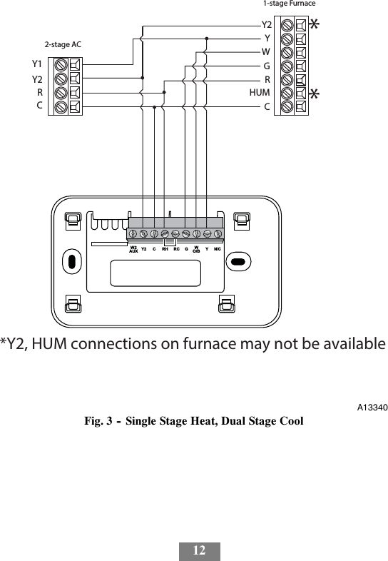
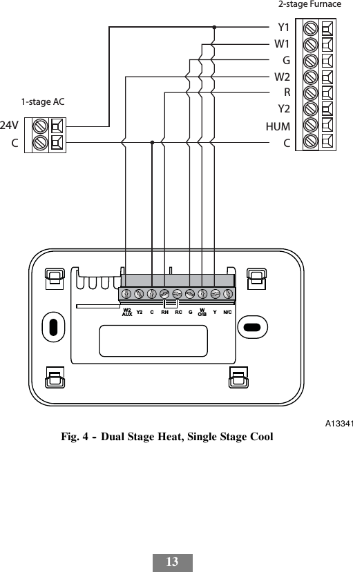
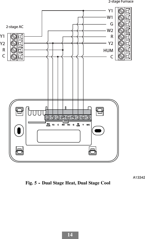
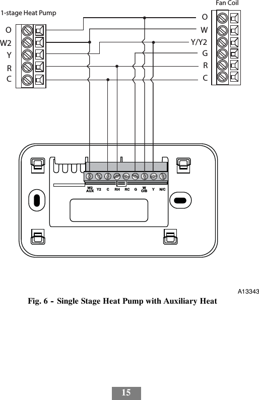
Users Manual Bryant
Navigation menu
Upload a User Manual
Namespaces
Wiki Guide
HTML
PDF
Info
Views
User Manual
Discussion / Help
Navigation
![22dMENU Pressing MENU displays a list of all available options. Ifa menu is currently displayed, pressing MENU will cancel anyunsaved changes and return to the Home screen.MENUA13357dBACK On a menu screen, press BACK to go back to the previ-ous screen.BACKA13358On--Screen KeyboardIf you need to type in any information, an on--screen keyboard willappear. To enter a letter or number, move to the character by pressing thearrow keys and then press OK to select it.Select the [Caps] key to enter capital letters; select the [&@#] key toenter commonly used symbols. If you make a mistake, press the [X]backspace key to delete the text.To keep your changes, select Save. To cancel your changes, pressBACK.](https://usermanual.wiki/ecobee-orporated/EBSTATSI01.Users-Manual-Bryant/User-Guide-2930769-Page-24.png)