ecobee orporated EBSTATSI01 Smart Thermostat User Manual EMS Si
ecobee Incorporated Smart Thermostat Users Manual EMS Si
UserManual.wiki
>
ecobee orporated
>
EBSTATSI01 User Manual
>
Users Manual EMS Si
Contents
1.
Users Manual Climate Master Revised
2.
Users Manual Daikin Revised
3.
Users Manual Bryant
4.
Users Manual Carrier
5.
Users Manual EMS Si
6.
Users Manaul Smart SI
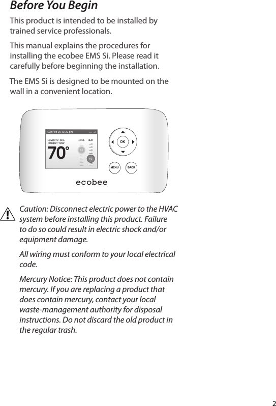
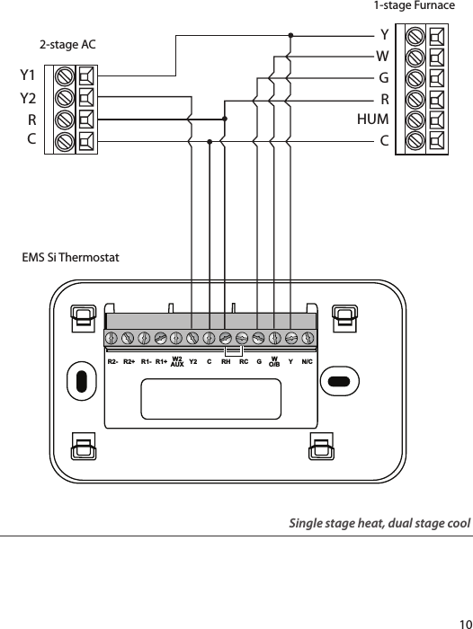
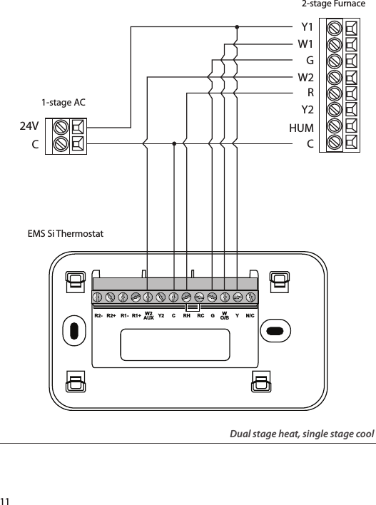
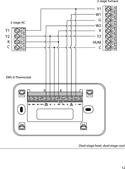
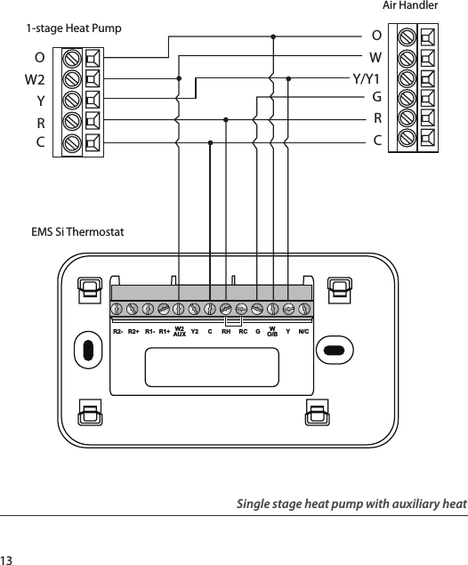
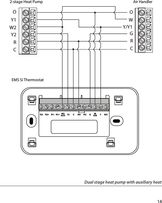
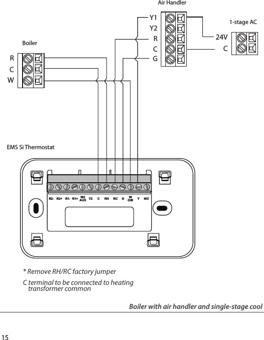
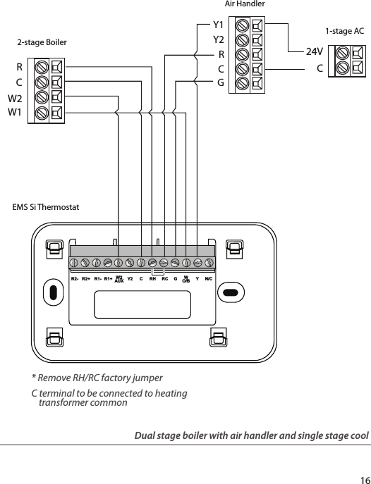
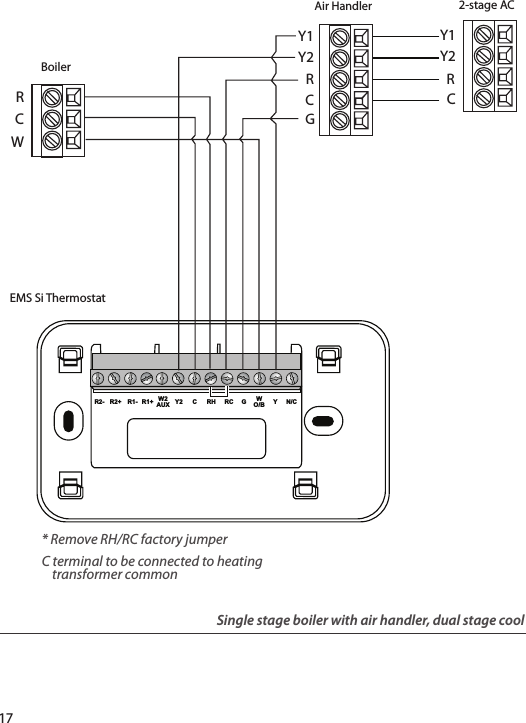
Users Manual EMS Si
Navigation menu
Upload a User Manual
Namespaces
Wiki Guide
HTML
PDF
Info
Views
User Manual
Discussion / Help
Navigation