ecobee orporated EBSTATSI01 Smart Thermostat User Manual Daikin Revised
ecobee Incorporated Smart Thermostat Users Manual Daikin Revised
Contents
Users Manual Daikin Revised
www.DaikinENVi.com
Daikin North America LLC.
5151 San Felipe Dr, Suite 500
Houston, TX 77056 USA
DACA-TS1-1
Daikin ENVi Thermostat
Installation Manual

SAFETY CONSIDERATIONS
Read these SAFETY CONSIDERATIONS for Installation carefully before installing the
Daikin ENVi thermostat kit. After completing the installation, make sure that the unit
operates properly.
Instruct the customer on how to operate and maintain the thermostat. Inform
customers that they should store this Installation Manual with the Operation
Manual for future reference.
Always use a licensed installer or contractor to install this product. Improper
installation can result in electric shock or re.
All electrical work must be carried out in accordance with local, state and national
regulations.
Safely dispose all packing materials in accordance with federal/state/local laws or
ordinances.
Only qualied personnel must carry out the installation work. Installation must be
done in accordance with this installation manual. Improper installation may result
in electric shock or re.
Use only specied accessories and parts for installation work. Failure to use
specied parts may result in electric shock, re or the unit failing.
Make sure that all wiring is secured, that specied wires are used, and that no
external forces act on the terminal connections or wires. Improper connections or
installation may result in re.
Before touching electrical parts, turn o the unit.
Do not touch the thermostat with wet ngers. Touching the thermostat with wet
ngers can cause electric shock.
Do not allow children to play with the unit to prevent injury.
Do not install the thermostat in the following locations:
- Where a mineral oil mist or oil spray or vapor is produced, for example, in a
kitchen.
- Where corrosive gas such as sulfurous acid gas is produced.
- Near machinery emitting electromagnetic waves. Electromagnetic waves may
disturb the operation of the control system and cause the unit to malfunction.
Disposal of the unit must be done in accordance with the relevant local, state and
national regulations.
CONTENTS
GETTING STARTED 1
Welcome 1
Contractor Thermostat Registration 1
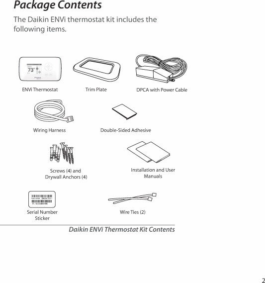
Package Contents 2
Before You Begin 3
Daikin System Compatibility 4
Specications 5
Wiring Requirements 6
INSTALLING THE THERMOSTAT KIT 6
Step 1. Power O the Daikin Indoor Unit 6
Step 2. Position and Wire the DPCA 7
Step 3. Install the Daikin ENVi Thermostat 9
Step 4. Connect the Thermostat Wiring 11
Step 5. Mount the DPCA 12
Step 6. Power On Daikin Indoor Unit 12
NAVIGATING THE MENUS 13
Using the Navigation Buttons 13
CONFIGURING THE DAIKIN ENVi THERMOSTAT 15
Preferences 15
Installation Settings 16
Reset Equipment or User Settings 21
Rebooting the Daikin ENVi thermostat 22
Sensors 22
CONFIGURING REMINDERS AND ALERTS 23
List of Alerts 25
ONE-YEAR LIMITED WARRANTY 26
Approvals 27
FCC Compliance Statement 28
IC Statement 29
GETTING STARTED
Welcome
The Daikin ENVi thermostat kit has been
designed to ensure the installation process
is simple and ecient. This step-by-step
Installation Manual will walk you through all
aspects of the installation.
To ensure an on-going service relationship with
your customers, please register all of your Daikin
ENVi thermostats in your Contractor Portal.
Contractor Thermostat
Registration
Use the serial number sticker (included in
package) for Contractor Portal registration.
1
Before You Begin
This product is intended to be installed by
trained service professionals.
This manual explains the procedures for
installing the Daikin ENVi thermostat.
Please read it carefully before beginning the
installation.
For information on how to operate the Daikin
ENVi thermostat, please see the Daikin ENVi User
Manual.
The Daikin ENVi thermostat is designed to be
mounted on the homeowner’s wall in a
convenient location.
Caution: Disconnect electric power to the
Daikin Indoor Unit before installing this
product. Failure to do so could result in electric
shock and/or equipment damage.
All wiring must conform to your local electrical
code.
Mercury Notice: This product does not contain
mercury. If you are replacing a product that
does contain mercury, contact your local
waste-management authority for disposal
instructions. Do not discard the old product in
the regular trash.
!
3

4
Daikin System Compatibility
The Daikin ENVi thermostat is designed to
operate only with the Daikin Heat Pump and
Cooling Indoor Units where the BRC944 wired
remote controller is applicable.
The Daikin ENVi thermostat supports the
following systems:
Single-Split system
Multi-Split system (2 to 8 ports)
SkyAir FTXS Indoor Units
Applicable indoor unit models:
FTK, FTKN, FTKS, FTXG, FTX, FTXS, FTXN
(09/12 K(E)VJU requires KRP980B1 interface
adapter), CTXS, FDXS, CDXS and FVXS.
Models numbers ending in NMVJU will
require an interface adapter (KRP067A41 or
KRP980B2). Please consult the Daikin indoor
unit installation manual for the appropriate
adapter use.
The Daikin ENVi thermostat can also support a
single-stage auxiliary heater.
Any auxiliary heater that requires air ow
from the Indoor Unit should be equipped
with an air ow switch for safety. The indoor
unit fan could stop during the defrost cycle
and other situations.
!
Specications
Thermostat Specications
Temperature
Heat Set Point Range 45 to 80 °F (7 to 26.5 °C)
Cool Set Point Range 65 to 95 °F (18.5 to 35 °C)
Display Range 40 to 100 °F (5 to 37 °C)
Sensitivity +/- 1 °F (0.5 °C)
Operating Range 32 to 130 °F (0 to 55 °C)
Humidity
Display Range 20 to 90% R.H.
Sensitivity +/- 5% R.H.
Operating Range 5 to 95% R.H.
(non-condensing)
Auxiliary Heater Relay
Electric Rating 30VAC, Max Current 3A
Dimensions
Width x Height x Depth 5.5 x 3.25 x 1 inches
(139.5 x 82.5 x 25 mm)
Power
24 VAC (3VA maximum) (provided from the DPCA)
DPCA Specications
Temperature
Operating Range 20 to 140 °F (–7 to 60 °C)
Humidity
Operating Range 5 to 95% R.H.
(non-condensing)
Dimensions
Width x Height x Depth 4.7 x 2.0 x 1.3 inches
(120 x 50 x 32.5 mm)
Power
208/230 VAC (provided from Indoor Unit)
5

6
Wiring Requirements
The Daikin ENVi thermostat uses 4-wire low-voltage cable to
connect to the Daikin Power and Communication Adapter
(DPCA) which in turn connects to the Indoor Unit.
The maximum wire length between the Daikin ENVi thermostat
and the DPCA is as follows:
18 AWG: 1250 ft/380 m
20 AWG: 800 ft/240 m
22 AWG: 500 ft/150 m
INSTALLING THE THERMOSTAT KIT
There are 5 steps to install the Daikin ENVi thermostat kit:
Step 1. Power O the Daikin Indoor Unit
Step 2. Position and Wire the DPCA
Step 3. Install the Daikin ENVi thermostat
Step 4. Connect the Thermostat Wiring
Step 5. Mount the DPCA
Step 6. Power On Daikin Indoor Unit
Step 1. Power O the Daikin Indoor Unit
Before installing the Daikin ENVi thermostat kit, disconnect the
power to the Indoor Unit.
WARNING: The Indoor Unit uses a high-voltage 208/230V
power source. Always DISCONNECT power to the Indoor Unit
before connecting any power wires. Failure to do can result in
death, re, or electrical shock
Step 2. Position and Wire the DPCA
The Daikin Power and Communication Adapter (DPCA) provides
an interface between the thermostat and Indoor Unit.
To install the DPCA:
1. Position the DPCA in a suitable location, away from water
and near the Indoor Unit (for example, a backside cavity of
a wall-mounted unit). The DPCA is not plenum rated and
should be mounted in a non-plenum space.
2. Connect the DPCA power cable to the Indoor Unit power
supply terminals. Ensure that the electrical connections are
securely tightened.
3. Remove the DPCA cover by grasping both sides and pulling
along the length of the DPCA.
4. Use the Wiring Harness to connect the P2 terminal
on the DPCA to the S21 terminal on the Indoor Unit’s
main PCB. Refer to the Daikin system installation
manual for information about accessing the S21
terminal.
7
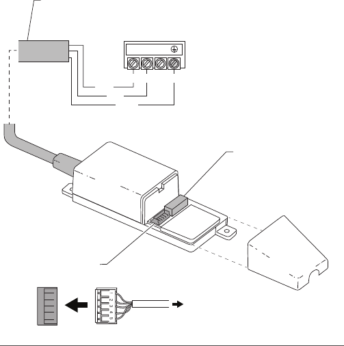
P1 Terminal
4-wire low-voltage
cable to thermostat
(not included)
P2 Terminal
Wire harness to Indoor Unit (included)
Power Cable
Power cable to terminal block on Indoor Unit
DPCA
123
Indoor Unit Terminal Block
Wire Harness
P2
Black
L1 L2 G
Red
Green
Wires to outdoor unit
are not shown
To terminal S21
on Indoor Unit
main control board
Cover
DPCA Wiring Connectors
8

Step 3. Install the Daikin ENVi Thermostat
The ideal location for the thermostat is approximately 5 ft (1.5 m)
above oor level in the main living area.
Do not install the thermostat:
Close to sources of heat such as incandescent lights
Near supply heating/cooling sources
In direct sunlight
On exterior, non-insulated or poorly insulated walls
In the kitchen or other areas of potentially high heat and/or
humidity
In an area that could restrict air ow
To install the thermostat:
1. If necessary, remove the previous thermostat.
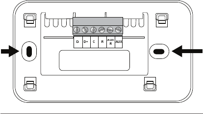
1. Gently separate the backplate from the Daikin ENVi
thermostat.
2. Place the thermostat backplate on the wall. Make sure that
any existing wires can be inserted through the opening for
the wiring.
If the backplate does not adequately cover the area where
the previous thermostat was installed, attach the trim plate
to the back of the backplate to increase its coverage.
3. Using the backplate as a template, mark the location of the
mounting holes on the wall as shown.
9
4. Move the backplate out of the way and make holes where
indicated in the previous step. The mounting holes can
accommodate a #6 pan-head screw. It is recommended to
use the included fasteners to ensure proper tting of the
front housing.
5. Use the included drywall plugs (or other suitable anchors) to
ensure the thermostat can be mounted securely to the wall.
6. Fasten the backplate and optional trim plate to the wall
using the screws provided (or other suitable screws).
The solid color indicates mounting holes
10
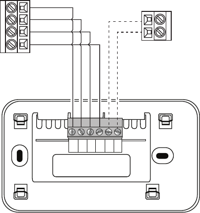
Step 4. Connect the Thermostat
Wiring
Use the eld-supplied 4-wire low-voltage cable
to connect the thermostat to the DPCA.
To connect the thermostat to the DPCA:
1. Connect the wires as shown:
2. Attach the Daikin ENVi thermostat to the
backplate. Ensure that the pins on the
thermostat align with the terminal block on
the backplate.
AUXRCD+D- AUX
R
P1 Terminal on DPCA
Daikin ENVi Thermostat
Optional Auxiliary Heater
R
C
D+
D-
24VAC
C
11
Step 5. Mount the DPCA
After you make the necessary wiring
connections, mount the DPCA by using the
adhesive sticker or mounting screws as needed.
Step 6. Power On Daikin Indoor
Unit
After you’ve completed the wiring, you can
apply power to the Daikin Indoor Unit. The
Daikin ENVi thermostat receives power from the
equipment and will automatically power on.
After you power on the Indoor Unit:
1. Verify the green LED on the DPCA has turned
on. Upon verication, re-attach the DPCA
cover.
2. Use the wire ties to secure the wires as
needed.
12
NAVIGATING THE MENUS
The Daikin ENVi thermostat has an easy-to-read
color screen that displays all the information
you need to congure the thermostat. Use
the navigation buttons on the right to quickly
change the temperature, access features, and
congure settings.
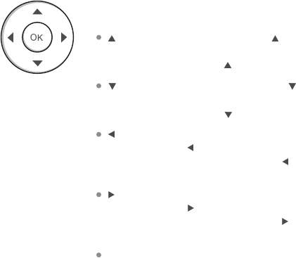
Using the Navigation Buttons
The navigation buttons let you select options
and control the Daikin ENVi thermostat.
(up) On the Home screen, press to
increase the temperature set point by 1°F
(0.5°C). For menus, press to move up.
(down) On the Home screen, press to
decrease the temperature set point by 1°F
(0.5°C). For menus, press to move down.
(left) On the Home screen, if Auto mode
is enabled, press to switch between heat
and cool set points. For menus, press to go
back to the previous screen.
(right) On the Home screen, if Auto mode
is enabled, press to switch between heat
and cool set points. For menus, press to
choose the currently highlighted option.
OK On a menu screen, press OK to choose
the currently highlighted option. If a
conguration option is selected, pressing OK
will keep its new value and return back to the
previous screen.
13
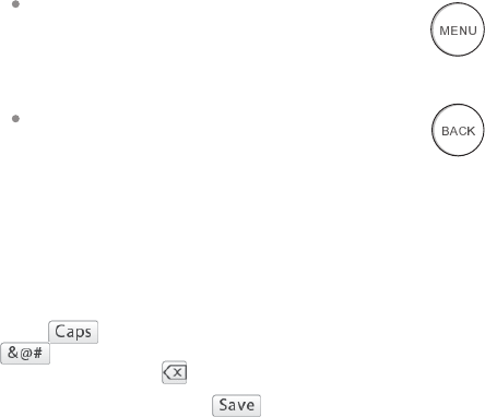
MENU Pressing MENU displays a list of
all available options. If a menu is currently
displayed, pressing MENU will cancel any
unsaved changes and return to the Home
screen.
BACK On a menu screen, press BACK to go
back to the previous screen.
On-Screen Keyboard
If you need to type in any information, an on-
screen keyboard will appear. To enter a letter or
number, move to the character by pressing the
arrow keys and then press OK to select it.
Select to enter capital letters; select
to enter commonly used symbols. If you
make a mistake, press to delete the text .
To keep your changes, select . To cancel
your changes, press BACK.
14

CONFIGURING THE DAIKIN
ENVi THERMOSTAT
The rst step after installing the Daikin ENVi
thermostat is to congure the thermostat
settings for the Indoor Unit.
Preferences
This section describes the user preferences that
should be congured during installation. For a
complete description of all user preferences, see
the Daikin ENVi User Manual.
Intelligent Eye
Some models of the Indoor Unit include an
intelligent eye, an infrared sensor that detects
room occupancy. It adjust the set point by 3.6°F
(2°C) if no movement is detected in order to
save energy (+3.6°F/+2°C if cooling, –3.6°F/–2°C
if heating).
To use intelligent eye, you must enable this
option in the Daikin ENVi thermostat and
then enable it with the Daikin wireless remote
controller. If enabled, the thermostat’s Smart
Recovery and Temp Alert functions are not
available.
By default, intelligent eye is disabled on the
thermostat.
Do NOT enable the intelligent eye with the Daikin
wireless remote controller when it is disabled on
the thermostat as this may cause suboptimal
operation and result in invalid recovery and alert
messages. Also, if an auxiliary heater is congured,
enabling intelligent eye may energize the auxiliary
heater more often than would normally be
required.
To congure the
intelligent eye:
From the Home screen,
press MENU.
Select Settings
Preferences.
Select Intelligent Eye.
Enable (Yes) or disable
(No) the intelligent eye
sensor.
15
Installation Settings
The Installation Settings let you congure
the equipment connected to the Daikin ENVi
thermostat.
Allow Auto Heat/Cool
Enabling this option allows the user to select
auto change-over as a system mode.
Only visible if the Indoor Unit supports heat or an
auxiliary heat source is congured.
Heat/Cool Min Delta
Sets the minimum dierence between the heat
mode set temperature and the cool mode set
temperature when the system mode is in auto-
changeover. The delta is adjustable from 2 to 10
°F (1.1 to 5.5 °C). The default value is 5 °F (2.8 °C).
Only visible if the Indoor Unit supports heat or an
auxiliary heat source is congured.
System Settings
The System Settings let you congure general
heat pump settings.
Min Cycle O Time Sets the minimum
equipment o time between cycles: 240 to
900 seconds (default is 240 seconds).
Min Cycle On Time Sets the minimum
equipment run time in cool mode: 1 to 20
min (default is 3 min).
Min Outdoor Temp Disables the compressor
when the outside air temperature reaches
the congured minimum setting. This
performs two functions. It prevents the
compressor from running when the outdoor
temperature is too low, thus resulting in
To congure the
system settings:
From the Home screen,
press MENU.
Select Settings
Installation Settings.
Congure the devices
connected to the
thermostat.
16

damage to the compressor. You can also set
this value to determine when you want the
auxiliary heat (if installed) to engage to help
meet the set temperature. The temperature
range is adjustable from –10 to 65 °F (–23.3 to
18.3 °C) or disabled by default.
This feature uses the Internet to obtain the
current outdoor temperature. If no Internet is
available, the Outdoor Unit’s temperature sensor
is used instead.
Cool Dierential Temp The minimum
dierence between the current temperature
and set temperature before the system calls
for cool. A smaller dierence means shorter
cycle times, whereas a larger dierence results
in longer cycle times. The temperature range
is adjustable from 0.5 to 3 °F (0.3 to 1.7 °C) in
0.5°F (0.3°C) increments.
Cool Dissipation Time The amount of time
the fan will run after the cool has been turned
o. Running the fan for a period of time allows
for any cooled air left in the ducts to circulate
throughout the home. The time is adjustable
from 0 to 900 seconds (default is 0 seconds).
AC Overcool Max When using the AC to
dehumidify, the setting congures how
many degrees below the current set point
the thermostat will run in order to reach the
dehumidify set point. Options are Disabled
(default) and 0.5 to 3 °F (0.3 to 1.8°C) in 0.5 F
(0.3°C) increments.
Heat Dierential Temp The minimum
dierence between the current temperature
and set temperature before the system calls
for heat. A smaller dierence means shorter
cycle times, whereas a larger dierence results
17

in longer cycle times. The temperature range
is adjustable from 0.5 to 3 °F (0.3 to 1.7 °C) in
0.5°F (0.3°C) increments. The default oset is
0.5°F (0.3°C).
If the Indoor Unit is AC only and an auxiliary
heater is congured, this option appears under
the Aux Heat Settings menu.
Heat Dissipation Time The amount of time
the fan will run after the heat set point has
been reached and the call for heat has been
turned o. Running the fan for a period
of time allows for heated air to circulate
throughout the home. The time is adjustable
from 0 to 900 seconds (default is 0 seconds).
If the Indoor Unit is AC only and an auxiliary
heater is congured, this option appears under
the Aux Heat Settings menu.
Indoor Unit Temp Oset Depending on its
type, the Indoor Unit uses a temperature
oset for the heating set point, taking
into consideration the higher sensing
temperature. The Daikin ENVi thermostat
applies the oset to the set point which is
sent to the Indoor Unit. The oset should be
3.5°F (2.0°C) for wall-mounted and ducted
indoor units, and 0°F (0°C) for oor-standing
indoor units (available in the future). The
oset range is adjustable from 0°F (0°C) to
5.5 °F (3.0°C) in 0.5°F (0.3°C) increments to
allow for future indoor unit expansions. The
default oset is 3.5°F (2.0°C).
Heat Pump to Aux Temp Delta The
minimum dierence between the current
temperature and the set temperature that
will activate Aux Heat (regardless if the
maximum run time of the heat pump was
18

reached). Options are Auto (default) and 1 to
10 °F (0.6 to 5.6°C).
Only visible if Indoor Unit supports heat and an
auxiliary heat source is also congured.
Heat Pump to Aux Runtime The maximum
amount of time the heat pump will run
before engaging Aux Heat. Options are Auto
(default), Disabled, and 10 to 180 minutes.
Only visible if Indoor Unit supports heat and an
auxiliary heat source is also congured.
Aux Heat Settings
The Aux Heat Settings congure an auxiliary heat
source.
If you want to test the auxiliary heater during
installation, set Aux Heat Installed to Yes and set
Allow HP with Aux Heat to No. Then, adjust the heat
set point to enable the auxiliary heater.
Aux Heat Installed When set to Yes,
congures the thermostat to control an
auxiliary heat source.
Aux Heat Requires Fan When set to Yes,
congures the thermostat to control the fan
when auxiliary heat is used.
Allow HP with Aux Heat When set to Yes,
it will turn on auxiliary heat in addition to
the heat pump. For information about how
auxiliary heat will be engaged with the heat
pump, see the settings Heat Pump to Aux
Temp Delta and Heat Pump to Aux Runtime.
Aux Min On Time Sets the minimum
equipment run time for auxiliary heat: 1 to 20
min (default is 5 min).
Max Outdoor Temp Congures the
maximum outdoor temperature threshold.
19

Above this level, the auxiliary heat will not be
activated. The temperature is adjustable from 0
to 80 °F (-17.8 to 26.5 °C) in increments of 0.5°F
(0.3°C). The default value is 70°F (21°C).
Fan Conguration
The Fan Conguration settings map the Indoor
Unit’s internal fan speeds to the fan speed options
displayed to the user on the thermostat.
Heating Mode Speeds Congures fan speed
when the user selects High, Medium or Low
while the system is in heat mode. The possible
speeds for each value are High, Medium High,
Medium, Medium Low, and Low.
Cooling Mode Speeds Congures fan speed
when the user selects High, Medium or Low
while the system is in cool mode. The possible
speeds for each value are High, Medium High,
Medium, Medium Low, and Low.
Fan Only Mode Speeds Congures fan speed
when the user selects High, Medium or Low
while the system is not actively cooling or
heating the room. The possible speeds for
each value are High, Medium High, Medium,
Medium Low, and Low.
Aux Fan Min Speed Congures minimum fan
speed used when Aux Heat requires a fan. The
possible speed is High, Medium High, Medium,
Medium Low, or Low.
Force System O
Force System O is used to clear a latched system
error status in the indoor unit by turning o the
equipment for ve seconds after system servicing.
Operation will automatically resume with the
previous settings once complete.
20

Tstat Temp Correction
Lets you program an oset between the
real temperature at the thermostat and the
displayed temperature. If you nd that the
temperature where the thermostat is located
does not represent the room temperature,
change the oset to compensate for the
dierence. The correct temperature is adjustable
from +/- 10°F (+/-5 .6°C) in 0.5°F (0.3°C)
increments.
Installer Code
To prevent accidental modications to the
installation settings, you can enable the
following installer code: 3262. The code is xed
and cannot be changed.
Reset Equipment or User Settings
You can restore equipment or user settings on
the Daikin ENVi thermostat back to their factory
defaults.
Reset Registration Resets the connection
between the Daikin ENVi thermostat and the
user’s personalized Web Portal.
Preferences and Schedule Resets
all preferences, reminders, alerts and
programming back to the default state.
HVAC Equipment Settings Resets the
conguration of the Indoor Unit and/or
auxiliary heat equipment.
All Settings Resets the Daikin ENVi
thermostat back to its default factory
settings.
To reset the Daikin ENVi
thermostat:
From the Home screen,
press MENU.
Select Settings Reset.
Select the desired reset
method.
21
Reset Contractor Info Resets any
information about the Contractor who
installed the Daikin ENVi thermostat.
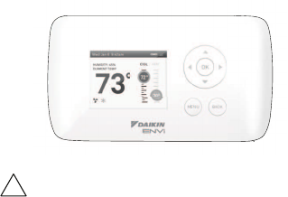
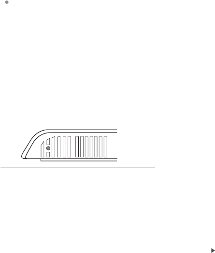
Rebooting the Daikin ENVi
thermostat
You can reboot the Daikin ENVi thermostat by
pressing the physical hardware reset button,
located through an opening in the bottom left
corner of the Daikin ENVi thermostat. Rebooting
will not alter programming or conguration
options.
Sensors
By default, the Daikin ENVi thermostat’s Internal
Sensor is used for an accurate indication of the
room temperature (recommended setting).
The Indoor Unit is also equipped with a room
temperature sensor which you can use instead.
You can also enable both sensors to provide
an average sensing temperature. However, the
Indoor Unit sensor and averaging methods are
not recommended because the Indoor Unit
sensor, especially wall-mounted models, can be
aected by certain operations such as starting
up and defrosting in a short time which may
cause improper control of the indoor unit by the
ENVi Thermostat.
Reset button
To select the
temperature sensor:
From the Home screen,
press MENU.
Select Sensors
Congure.
Enable or disable each
sensor by selecting
Internal Sensor or Indoor
Unit and then selecting
Yes or No.
22
CONFIGURING REMINDERS
AND ALERTS
The Daikin ENVi thermostat can generate
periodic maintenance reminders that help the
homeowner know when to perform periodic
maintenance.
The thermostat can also generate alerts if the
system detects an error or if the temperature in
the home goes over or under a pre-programmed
level (which protects the home from damage
due to freezing and/or excessive heat).
Alerts are displayed on the screen. They include
a description, error code (in the case of a
system error), and optional technician contact
information.
If the homeowner registers the thermostat, the
alert will be emailed to them and be displayed in
the web portal.
System Service
The system service (maintenance) reminder
generates an alert telling the homeowner that
regularly scheduled maintenance is required.
This reminder, along with technician contact
information, can be displayed on the screen.
If homeowners register their thermostats, the
reminders will be emailed to them and be
displayed in the web portal.
You can set the Last Service date, turn the
Reminder On or O, and to set the Frequency of
the maintenance interval in months.
To congure Reminders
and Alerts
From the Home screen,
press MENU.
Select Reminders and
Alerts.
Congure the Reminder
and Alert settings as
required.
23

Low Temp Limit
Sets the temperature at which the thermostat
will generate a Low Temperature Limit alert. The
range can be:
Disabled – No alert will be generated.
Enabled –Set temperature range of 35 to 68
°F (1.5 to 20 °C).
High Temp Limit
Sets the temperature at which the thermostat
will generate a High Temperature Limit alert. The
range can be:
Disabled – No alert will be generated.
Enabled – Set temperature range of 60 to
104 °F (15.5 to 40 °C).
Display Alerts on Thermostat
Select No if you do not want any of the alerts
to be displayed on the Daikin ENVi thermostat
screen. Alerts will continue to be displayed on
the web portal and sent via email.
Enable Heating/Cooling Alerts
Select No to disable alerts for heat/cool error
conditions. If disabled, alerts indicating that the
system failed to heat or cool will not be appear
in the screen, web portal, or emails.
24

List of Alerts
Below is a complete list of alerts. Depending on your conguration,
some of these may not apply.
Low Temp Limit Temperature in the home is too low.
High Temp Limit Temperature in the home is too high.
Heat Not
Responding
The system has failed to heat the home.
Cool Not
Responding
The system has failed to cool the home.
System Service HVAC system due for regular maintenance.
Auxiliary Heat Run
Time
Auxiliary heat source is running too often.
Auxiliary Outdoor
Temperature
Your auxiliary heat has been called to run when the
outdoor temperature exceeds the programmed set
point.
System error, service
required
A system error occurred.
If the Indoor Unit’s status LED is blinking after
the error has been corrected, select Settings
Installation Settings Force System O to reset
the latched error status and turn o the blinking
LED.
Lost communication Communication with the Indoor Unit has been lost.
Check the wiring connections between the DPCA,
ENVi thermostat and Indoor Unit. The green LED on
DPCA should be on and solid.
Upon initial power up of the system communication,
this alert may be generated. Wait up 10 minutes
for system to initialized before troubleshooting.
The alert will be removed automatically once
communication has been established.
25
ONE-YEAR LIMITED WARRANTY
Daikin North American LLC, (“Daikin”) warrants that for a period of one (1) year from the date of
purchase by the end-user (“Customer”), the Daikin ENVi thermostat (the “Product”) shall be free of
defects in materials and workmanship under normal use and service. During the limited warranty
period, Daikin shall, at its option, repair or replace any defective Products, at no charge. Any
replacement and/or repaired device are warranted for the remainder of the original limited warranty
or ninety (90) days, whichever is longer.
NO LABOR WARRANTY
This limited warranty will apply with respect to parts only and not labor. Accordingly, subject to the
conditions and limitations set forth herein, the limited warranty entitles the Customer to receive, at
the option of Daikin only, a repaired or replacement part.
If the Product is defective, please call the third party contractor (“Installing Contractor”). After
consulting with the Installing Contractor, Daikin will make the determination whether a replacement
Product can be sent to you or whether the Product should be returned to the following address:
Daikin North American LC., 5151 San Felipe Dr, Suite 500, Houston, TX 77056. In the event of a failure
of a Product, Customer may:
• contact the Installing Contractor from whom the Product was purchased to obtain an
equivalent replacement product, provided the Installing Contractor determines that the
returned Product is defective and Customer is otherwise eligible to receive a replacement
product
This limited warranty does not cover removal, freight or reinstallation costs and shall not apply if the
damages were found to be caused by something other than defects in materials or workmanship. The
limited warranty will be void and of no eect, and Daikin will have no liability to Customer or anyone,
including without limitation, if the Product:
• was operated/stored in abnormal use or maintenance conditions not prescribed in the User
Manual;
• is repaired, modied or altered by any source other than Daikin, its agents or a licensed Heating
Ventilating and Air Conditioning (HVAC) contractor and Daikin expressly authorizes such repair;
• the Product was subjected to misuse, abuse, negligence , electrical fault, improper handling or
improper or inadequate maintenance accident or acts of nature;
• the Product is not operated or maintained and serviced in compliance with the printed
instructions and recommendations of Daikin;
• the serial number of the Product has been altered, defaced, or removed;
• the Product is mishandled by Customer or any third party;
• lightning, uctuations in electrical power or acts of God have occurred;
• problems arise from normal wear and tear;
• the Product has not been purchased from an authorized Daikin distributor or sales
representative (an “Authorized Seller”) or from a party or contractor who has purchased the
Product from an Authorized Seller;
• was not installed by a licensed Heating Ventilating and Air Conditioning (HVAC) contractor or
was installed improperly.
26
The limited warranty is for repair or replacement of parts or Product only. Except to that limited
extent, Daikin will not under any circumstances be liable for any loss, cost, damage, or expense of
any kind arising out of a breach of this limited warranty or otherwise. Without intending to limit
the foregoing sentence, it is specically provided as follows: DAIKIN SHALL NOT BE LIABLE FOR ANY
INDIRECT, INCIDENTAL, CONSEQUENTIAL, EXEMPLARY, SPECIAL, OR PUNITIVE DAMAGES, OR FOR
ANY LOSS OF REVENUE, PROFIT OR USE, ARISING OUT OF A BREACH OF THIS LIMITED WARRANTY
(INCLUDING BUT NOT LIMITED TO DAMAGE RESULTING FROM MOLD OR OTHER CONTAMINATES)
OR IN CONNECTION WITH THE SALE, MAINTENANCE, USE, OPERATION, SERVICING OR REPAIR OF
ANY DAIKIN PRODUCT. IN NO EVENT WILL DAIKIN BE LIABLE FOR ANY AMOUNT GREATER THAN THE
PURCHASE PRICE OF A DEFECTIVE PRODUCT.
THIS LIMITED WARRANTY IS THE SOLE AND EXCLUSIVE WARRANTY FOR DAIKIN PRODUCT, AND IS
IN LIEU OF ALL OTHER WARRANTIES EXPRESS OR IMPLIED, IN LAW OR IN FACT. DAIKIN SPECIFICALLY
DISCLAIMS ALL OTHER WARRANTIES EXPRESS OR IMPLIED, INCLUDING BUT NOT LIMITED TO ALL
IMPLIED WARRANTIES OF MERCHANTABILITY AND OF FITNESS FOR A PARTICULAR USE OR PURPOSE
OR OF NON-INFRINGEMENT, OR ANY IMPLIED WARRANTY ARISING OUT OF A COURSE OF DEALING
OR OF PERFORMANCE OR USAGE OF TRADE. NO PERSON OR ENTITY IS AUTHORIZED TO BIND DAIKIN
TO ANY OTHER WARRANTY, OBLIGATION OR LIABILITY FOR ANY DAIKIN PRODUCT. ACCEPTANCE,
INSTALLATION, OPERATION OR USE OF THE DAIKIN PRODUCT FOR WHICH THIS WARRANTY IS ISSUED
WILL CONSTITUTE ACCEPTANCE OF THE TERMS HEREOF.
SOME JURISDICTIONS MAY NOT ALLOW THE EXCLUSION OR LIMITATION OF INDIRECT, INCIDENTAL
OR CONSEQUENTIAL DAMAGES, OR OF ANY EXPRESS OR IMPLIED WARRANTIES, SO TO SUCH EXTENT
THE ABOVE EXCLUSIONS MAY NOT APPLY TO CERTAIN CUSTOMERS. THIS LIMITED WARRANTY
PROVIDED BY DAIKIN GIVES CUSTOMERS SPECIFIC LEGAL RIGHTS, AND CUSTOMERS MAY ALSO
HAVE OTHER RIGHTS WHICH VARY FROM JURISDICTION TO JURISDICTION. The disclaimers of liability
included in this limited warranty shall remain in eect and shall continue to be enforceable in the
event that any remedy herein shall fail of its essential purpose
No one is authorized by Daikin to modify this limited warranty in any respect or to create for Daikin
any other obligation or liability in connection with the Product unless done so in a written agreement
bearing the handwritten signature of the President of Daikin. Customer agrees that any purported
change by Daikin shall be null and void unless the President of Daikin shall have expressly so agreed
to such change.
This limited warranty gives you specic rights, and you may also have other rights which vary from
jurisdiction to jurisdiction. If you have any questions regarding this limited warranty, please write
Daikin North America LLC., 5151 San Felipe Dr, Suite 500, Houston TX 77056.
Approvals
This product was designed and built in accordance to RoHS directive
2002/95/EC and contains no hazardous substances as dened by this
directive.
27
28
FCC Compliance Statement
Compliance notice:
This equipment has been tested and found to comply with the limits for a
Class B digital device, pursuant to part 15 of the FCC Rules. These limits are
designed to provide reasonable protection against harmful interference in
a residential installation. This equipment generates, uses and can radiate
radio frequency energy and, if not installed and used in accordance with
the instructions, may cause harmful interference to radio communications.
However, there is no guarantee that interference will not occur in a
particular installation. If this equipment does cause harmful interference
to radio or television reception, which can be determined by turning
the equipment o and on, the user is encouraged to try to correct the
interference by one or more of the following measures:
• Reorient or relocate the receiving antenna.
• Increase the separation between the equipment and receiver.
• Connect the equipment into an outlet on a circuit dierent from that to
which the receiver is connected.
• Consult the dealer or an experienced radio/TV technician for help.
This device complies with part 15 of FCC rules. Operation is subject to the
following two conditions:
1. This device may not cause harmful interference.
2. This device must accept any interference received, including
interference that may cause undesired operation.
Change or modications that are not expressly approved by the
manufacturer could void the user’s authority to operate the equipment.
RF Exposure Information
This equipment complies with FCC radiation exposure limits set forth for an
uncontrolled environment. In order to avoid the possibility of exceeding the
FCC radio frequency exposure limits, human proximity to the antenna shall
not be less than 8 inches during normal operation.

Industry Canada (IC)
Compliance Notice:
This device complies with Industry Canada license-exempt RSS standard(s).
Operation is subject to the following two conditions:
1. This device may not cause interference, and
2. This device must accept any interference, including interference that
may cause undesired operation of the device.
This Class B digital apparatus complies with Canadian ICES-003.
RF Exposure Statement:
This equipment complies with IC RSS-102 radiation exposure limits set
forth for an uncontrolled environment. This transmitter must be installed to
provide a separation distance of at least 20 cm from all persons and must
not be collocated or operating in conjunction with any other antenna or
transmitter.
FCC ID: XF6-RS91-10N1102 IC: 8407A-91101102
Warning: Changes or modications not expressly approved by Daikin North
America LLC. could void the user’s authority to operate the equipment.
29