ecobee orporated EBSTATSI01 Smart Thermostat User Manual TC WHS 02SI
ecobee Incorporated Smart Thermostat TC WHS 02SI
Contents
Users Manual Carrier
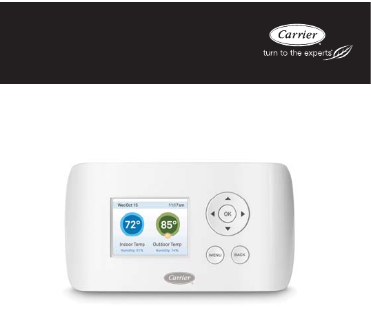
TC-WHS01
Comfort™ Series Wi-FirThermostat
Installation Instructions
NOTE: Read the entire instruction manual before starting the installation.
TABLE OF CONTENTS
PAGE
GETTING STARTED 1...........................................
Safety Considerations 1...........................................
Before You Begin 2..............................................
HVAC System Compatibility Information 3...........................
Approvals 4....................................................
FCC Compliance Statement 4......................................
Specifications 6.................................................
Wiring Requirements 7...........................................
INSTALLATION 8...............................................
Step 1. Power Off HVAC Equipment 8...............................
Step 2. Remove Existing Thermostat 8...............................
Step 3. Install the Thermostat 8.....................................
Step 4. Connect the Wiring 10......................................
Step 5. Power On the HVAC Equipment 20...........................
NAVIGATING THE MENUS 21....................................
CONFIGURING THE THERMOSTAT 23............................
Equipment 23..................................................
Thresholds 25..................................................
Test Equipment 28..............................................
Reset HVAC Equipment Settings 29.................................
Performing a Hardware Reset 29...................................
Rebooting the thermostat 29.......................................
Configuring Reminders and Alerts 30................................
Alerts 31......................................................
List of Alerts 32................................................

1
GETTING STARTED
Safety Considerations
Improper installation, adjustment, alteration, service, maintenance, or use
can cause explosion, fire, electrical shock, or other conditions which may
cause death, personal injury or property damage. Consult a qualified
installer, service agency or your distributor or branch for information or
assistance. The qualified installer or agency must use factory--authorized
kits or accessories when modifying this HVAC system. Refer to the
individual instructions packaged with the kits or accessories when
installing.
Follow all safety codes. Wear safety glasses, protective clothing, and
work gloves. Have a fire extinguisher available. Read these instructions
thoroughly and follow all warnings and cautions included in literature
and attached to the unit. Consult local building codes and the current
edition of the National Electrical Code (NEC) NFPA 70. In Canada, refer
to the current editions of the Canadian Electrical Code CSA C22.1.
Recognize safety information. When you see this symbol on the unit
and in instructions or manuals, be alert to the potential for personal
injury. Understand the signal words DANGER,WARNING,and
CAUTION. These words are used with the safety--alert symbol.
DANGER identifies the most serious hazards, which will result in severe
personal injury or death. WARNING signifies hazards, which could
result in personal injury or death. CAUTION is used to identify unsafe
practices, which may result in minor personal injury or product and
property damage. NOTE is used to highlight suggestions which will
result in enhanced installation, reliability, or operation.
2
Before You Begin
This product is intended to be installed by trained service professionals.
This manual explains the procedures for installing the Carrier
ComforttSeries Wi--FiThermostat. Please read it carefully before
beginning the installation.
For information on how to operate the Comfort Series Wi--Fi Thermostat,
please see the Comfort Series Wi--Fi Thermostat Owner’s Manual.
The Comfort Series Wi--Fi Thermostat is designed to be mounted on the
homeowner’s wall in a convenient location.
A13335
PERSONAL INJURY HAZARD
Disconnect electric power to the HVAC system before
installing this product. Failure to do so could result in electric
shock and/or equipment damage.
All wiring must conform to your local electrical code.
Mercury Notice: This product does not contain mercury. If
you are replacing a product that does contain mercury, contact
your local waste--management authority for disposal
instructions. Do not discard the old product in the regular
trash.
CAUTION
!

3
HVAC System Compatibility Information
The Comfort Series Wi--Fi Thermostat is designed to operate with
low--voltage heating and cooling systems. It is not designed for use with
line--voltage or millivolt heating and cooling systems.
The Comfort Series Wi--Fi Thermostat supports:
dUp to 2 heat and 2 cool stages on a conventional system.
dUp to 3 heat and 2 cool stages on a heat pump system.
The Comfort Series Wi--Fi Thermostat supports the following
equipment:
Equipment Supported?
Gas / Oil / Electric heating
(uptotwostages)
YES
Heat pump with auxiliary heat
(up to three stages)
YES
Geothermal Heat Pump YES
Dual fuel systems YES
Standard electric cooling
(uptotwostages)
YES
Boilers YES

4
Approvals
This product was designed and built in accordance to RoHS directive
2002/95/EC and contains no hazardous substances as defined by this
directive.
Federal Communications Commission (FCC)
Compliance Notice:
This equipment has been tested and found to comply with the limits for a
Class B digital device, pursuant to part 15 of the FCC Rules. These limits
are designed to provide reasonable protection against harmful
interference in a residential installation. This equipment generates, uses
and can radiate radio frequency energy and, if not installed and used in
accordance with the instructions, may cause harmful interference to radio
communications. However, there is no guarantee that interference will
not occur in a particular installation. If this equipment does cause harmful
interference to radio or television reception, which can be determined by
turning the equipment off and on, the user is encouraged to try to correct
the interference by one or more of the following measures:
dReorient or relocate the receiving antenna.
dIncrease the separation between the equipment and receiver.
dConnect the equipment into an outlet on a circuit different from
that to which the receiver is connected.
dConsult the dealer or an experienced radio/TV technician for help.
This device complies with part 15 of FCC rules. Operation is subject to
the following two conditions:
1. This device may not cause harmful interference.
2. This device must accept any interference received, including inter-
ference that may cause undesired operation.
Change or modifications that are not expressly approved by the
manufacturer could void the user’s authority to operate the equipment.

5
RF Exposure Information
This equipment complies with FCC radiation exposure limits set forth for
an uncontrolled environment. In order to avoid the possibility of
exceeding the FCC radio frequency exposure limits, human proximity to
the antenna shall not be less than 20cm during normal operation.
Industry Canada (IC)
Compliance Notice:
This device complies with Industry Canada license--exempt RSS
standard(s).
Operation is subject to the following two conditions:
1. This device may not cause interference, and
2. This device must accept any interference, including interference
that may cause undesired operation of the device.
This Class B digital apparatus complies with Canadian ICES--003.
RF Exposure Statement:
This equipment complies with IC RSS--102 radiation exposure limits set
forth for an uncontrolled environment. This transmitter must be installed
to provide a separation distance of at least 20 cm from all persons and
must not be collocated or operating in conjunction with any other
antenna or transmitter.

6
Specifications
Temperature Ranges
Heat: 50to88°F (10 to 31°C) by default,
adjustable from 50 to 90°F (10 to 32°C)
Cool: 52to90°F(11to32°C) by default,
adjustable from 50 to 90°F (10 to 32°C)
Display: 40 to 100°F(5to37°C)
Sensitivity: +/-- 1°F(0.5°C)
Operating 32 to 130°F(0to55°C)
Humidity Range
Display: 20 to 90% R.H.
Sensitivity: +/-- 5% R.H.
Operating: 5 to 95% R.H. (non--condensing)
Dimensions
Thermostat: 5.5” W x 3.25” H x 1” D
(139.5mm W x 82.5mm H x 25mm D)
Power Consumption
24VAC (3VA maximum)
7
Wiring Requirements
The following table shows the maximum wire lengths allowed:
Thermostat to HVAC Equipment
18 AWG 20 AWG 22 AWG
128 ft (380m) 80 ft (240m) 50 ft (150m)
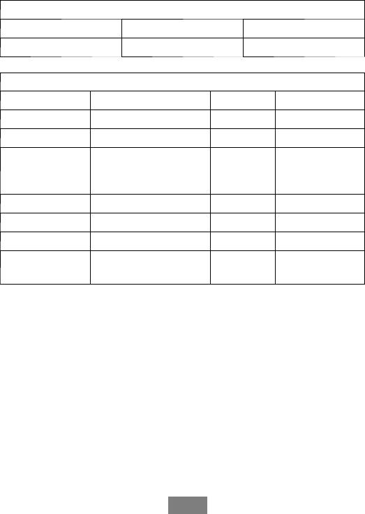
Terminal Description and Electrical Ratings
Terminal Description Voltage Current (Max)
N/C Unused N/A N/A
Y 1st Stage Compressor 24V AC 2A
W(O/B) 1st Stage Heating or
Reversing Valve
Changeover
24V AC 2A
GFan 24V AC 2A
CCommon 24V AC 2A
Y2 2nd Stage Compressor 24V AC 2A
W2 (AUX) 2nd Stage Heating or
1st Stage Aux Heat
24V AC 2A
NOTE: Factory jumper installed between RC and RH. Remove jumper for
2--transformer applications. See wiring diagrams for additional information.

8
INSTALLATION
There are 5 steps to install the thermostat:
Step 1 — Power Off HVAC Equipment
Step 2 — Remove Existing Thermostat
Step 3 — Install the Wi--Fi Thermostat
Step 4 — Connect the Wiring
Step 5 — Power On HVAC Equipment
Step 1. Power Off HVAC Equipment
Before disconnecting the existing thermostat, or installing the Comfort
Series Wi--Fi Thermostat, disconnect the power to the heating and air
conditioning equipment.
Step 2. Remove Existing Thermostat
Disconnect the wires to the existing thermostat and remove it from the
wall.
Step 3. Install the Comfort Series Wi--Fi Thermostat
The ideal location for the thermostat is approximately 5 ft (1.5 m) above
floor level in the main living area.
Do not install the thermostat:
dClose to sources of heat such as incandescent lights
dNear supply heating/cooling sources
dIn direct sunlight
dOn exterior, non--insulated or poorly insulated walls
dIn the kitchen or other areas of potentially high heat and/or hu-
midity
dIn an area that could restrict air flow
9
To install the thermostat:
3. Gently separate the backplate from the thermostat.
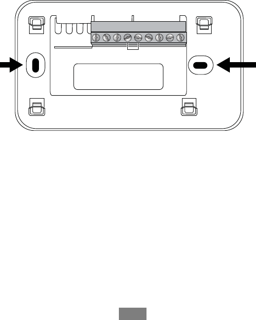
4. Place the thermostat backplate on the wall. Make sure that any ex-
isting wires can be inserted through the opening on the backplate.
5. Using the backplate as a template, mark the location of the mount-
ing holes on the wall as shown below.
YN/C
W
O/B
GRCRHCY2
W2
AUX
A13338
Fig. 1 -- The solid color indicates mounting holes
6. Move the backplate out of the way and make holes where indicat-
ed in Step 3. The mounting holes can accommodate a #6 pan--
head screw. It is recommended to use the included fasteners to en-
sure proper fitting of the front housing.
7. Use the included drywall plugs (or other suitable anchors) to en-
sure the thermostat can be mounted securely to the wall.
8. Fasten the backplate to the wall using the screws provided (or oth-
er suitable screws).

10
Step 4. Connect the Wiring
You need to use low--voltage cable to connect the thermostat to the
HVAC equipment. Check the wiring diagrams on the proceeding pages
for the number of wires required.
NOTE: There is a factory installed jumper between R/H and R/C.
Ensure any unused wires do not have exposed bare copper conductors.
To connect the thermostat to the equipment:
1. Connect the wires as shown in the wiring diagrams.
2. Attach the The Comfort Series Wi--Fi Thermostat to the backplate.
Ensure that the pins on the thermostat align with the terminal
block on the backplate.
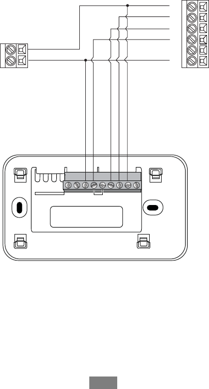
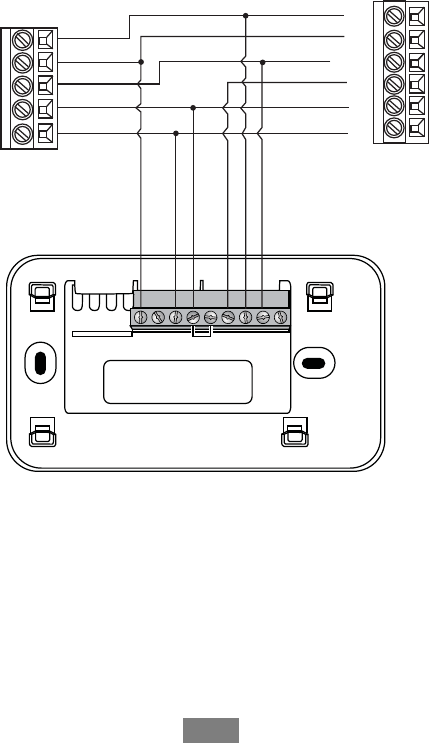
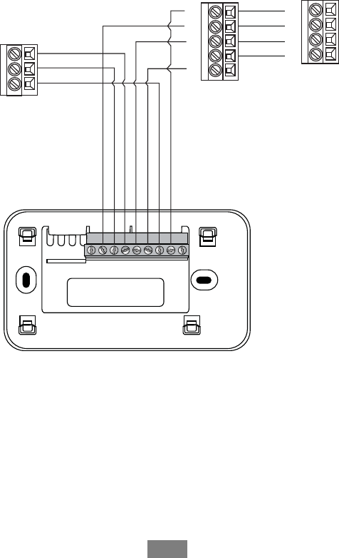
Wiring Diagrams
The following diagrams show how to connect the thermostat terminals to
various HVAC equipment.
11
YN/C
W
O/B
GRCRHCY2
W2
AUX
1-stage AC
C
24V
Y
G
R
W
C
HUM
1-stage Furnace
A13339
Fig. 2 -- Single Stage Heat / Cool
12
2-stage AC
Y2
R
C
Y1
Y
G
R
W
C
HUM
1-stage Furnace
YN/C
W
O/B
GRCRHCY2
W2
AUX
Y2
*
*Y2, HUM connections on furnace may not be available
*
A13340
Fig. 3 -- Single Stage Heat, Dual Stage Cool
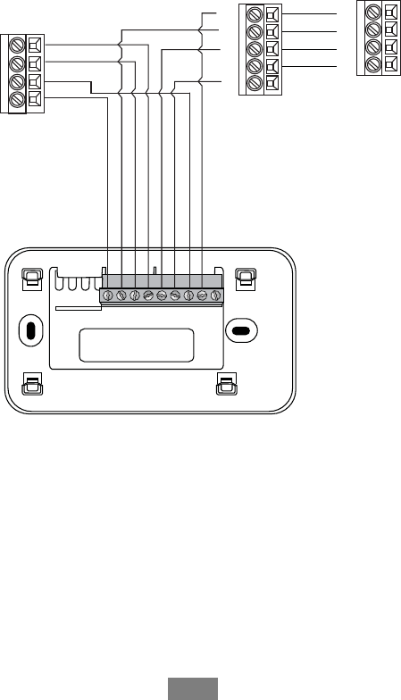
13
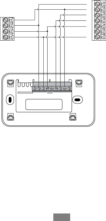
YN/C
W
O/B
GRCRHCY2
W2
AUX
Y1
G
W2
W1
HUM
C
R
Y2
2-stage Furnace
1-stage AC
C
24V
A13341
Fig. 4 -- Dual Stage Heat, Single Stage Cool
14
YN/C
W
O/B
GRCRHCY2
W2
AUX
Y1
G
W2
W1
HUM
C
R
Y2
2-stage Furnace
2-stage AC
Y2
R
C
Y1
A13342
Fig. 5 -- Dual Stage Heat, Dual Stage Cool
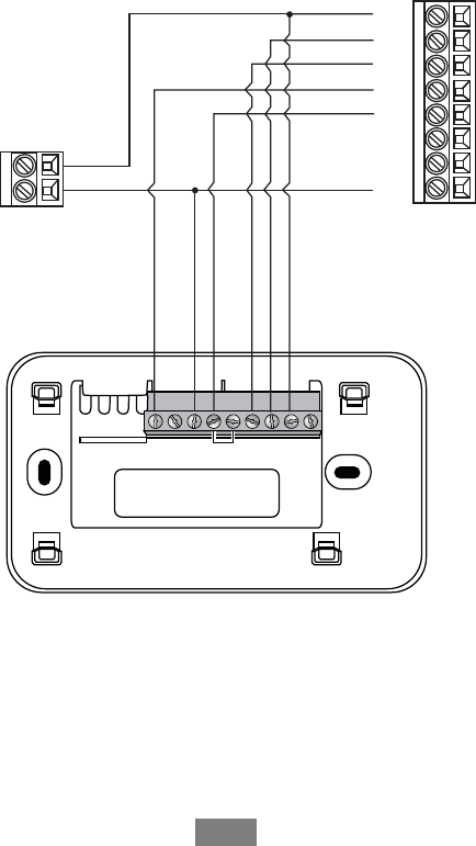
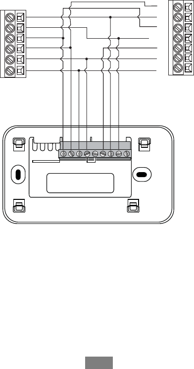
15
YN/C
W
O/B
GRCRHCY2
W2
AUX
O
W
Y/Y2
C
G
R
Fan Coil
1-stage Heat Pump
W2
R
Y
C
O
A13343
Fig. 6 -- Single Stage Heat Pump with Auxiliary Heat
16
YN/C
W
O/B
GRCRHCY2
W2
AUX
O
W
Y1
C
G
R
Fan Coil
2-stage Heat Pump
W2
Y1
R
Y2
C
O
Y2
*
*Y2 connection on fan coil may not be available
A13344
Fig. 7 -- Dual Stage Heat Pump with Auxiliary Heat
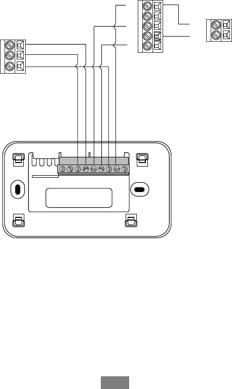
17
YN/C
W
O/B
GRCRHCY2
W2
AUX
1-stage AC
C
24V
Boiler
C
R
W
Y1
R
C
Y2
G
Fan Coil
* Remove RH/RC factory jumper
C terminal to be connected to heating
transformer common
A13345
Fig. 8 -- Boiler with Fan Coil and Single Stage Cool
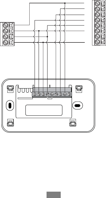
18
YN/C
W
O/B
GRCRHCY2
W2
AUX
1-stage AC
C
24V
2-stage Boiler
C
W2
R
W1
Y1
R
C
Y2
G
Fan Coil
* Remove RH/RC factory jumper
C terminal to be connected to heating
transformer common
A13346
Fig. 9 -- Dual Stage Boiler with Fan Coil and Single Stage Cool
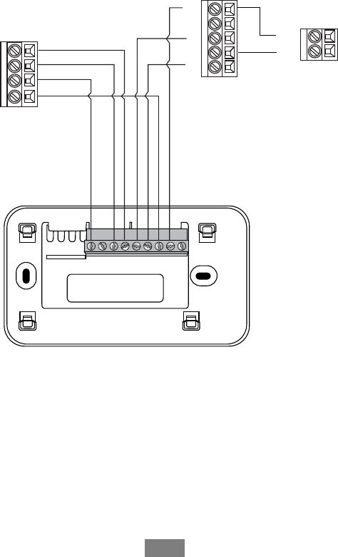
19
YN/C
W
O/B
GRCRHCY2
W2
AUX
2-stage AC
C
Boiler
C
W
R
Y1
RR
C
Y2
Y1
Y2
G
Fan Coil
* Remove RH/RC factory jumper
C terminal to be connected to heating
transformer common
A13347
Fig. 10 -- Single Stage Boiler with Fan Coil, Dual Stage Cool
20
YN/C
W
O/B
GRCRHCY2
W2
AUX
2-stage AC
C
2-stage Boiler
C
W2
W1
R
Y1
RR
C
Y2
Y1
Y2
G
Fan Coil
* Remove RH/RC factory jumper
C terminal to be connected to heating
transformer common
A13348
Fig. 11 -- Dual Stage Boiler with Fan Coil, Dual Stage Cool
Step 5. Power On HVAC Equipment
After you’ve completed the wiring, you can apply power to the heating
and air conditioning equipment. The Comfort Series Wi--Fi Thermostat
receives power from the equipment and will automatically power on.

21
NAVIGATING THE MENUS
The Comfort Series Wi--Fi Thermostat has an easy--to--read color screen
that displays all the information you need to configure the thermostat.
Use the navigation buttons on the right to quickly change the
temperature, access features, and configure settings.
Using the Navigation Buttons
The navigation buttons located on the right of the Comfort Series Wi--Fi
Thermostat let you select options and control the thermostat.
OK
A13356
dY(up) On the Home screen, press Yto increase the temperature
set point by 1°F(0.5°C). For menus, press Yto move up.
dB(down) On the Home screen, press Bto decrease the tempera-
ture set point by 1°F(0.5°C). For menus, press Bto move
down.
dA(left) On the Home screen, if Auto mode is enabled, press A
to switch between heat and cool set points. For menus, press Ato
go back to the previous screen.
d"(right) On the Home screen, if Auto mode is enabled, press "
to switch between heat and cool set points. For menus, press "to
choose the currently highlighted option.
dOK On a menu screen, press OK to choose the currently high-
lighted option. If a configuration option is selected, pressing OK
will keep its new value and return back to the previous screen.

22
dMENU Pressing MENU displays a list of all available options. If
a menu is currently displayed, pressing MENU will cancel any
unsaved changes and return to the Home screen.
MENU
A13357
dBACK On a menu screen, press BACK to go back to the previ-
ous screen.
BACK
A13358
On--Screen Keyboard
If you need to type in any information, an on--screen keyboard will
appear. To enter a letter or number, move to the character by pressing the
arrow keys and then press OK to select it.
Select the [Caps] key to enter capital letters; select the [&@#] key to
enter commonly used symbols. If you make a mistake, press the [X]
backspace key, to delete the text.
To keep your changes, select Save. To cancel your changes, press
BACK.

23
Configuring the Thermostat
The first step after installing the Comfort Series Wi--Fi Thermostat is to
configure the settings for the various devices (such as a furnace or air
conditioner) that are being connected.
Equipment
The Equipment settings let you configure the devices connected to the
thermostat.
To configure the equipment settings:
From the Home screen, press MENU.
Select Settings "Installation Settings.
Select Equipment.
Configure the devices connected to the thermostat.
Heat Pump
This section lets you configure a heat pump with up to 2 heat/2 cool
stages plus an auxiliary heat source.
dGeothermal heat pump Select Yes if you are using a geothermal
heat pump. This helps the thermostat determine optimum perfor-
mance and default settings. If you select No, the system will opti-
mize the settings for an air--to--air heat pump.
dOB energize on cool If you choose Yes, the reversing valve out-
put (O/B terminal) will activate when there is a call for cooling. If
you select No, the relay will activate when there is call for heat.
dMin Cycle Off Time Configures the minimum compressor off
time between cycles (240 to 900 seconds).
dMin Outdoor Temp Disables the compressor when the outside
air temperature reaches the configured minimum setting. This
performs two functions. It prevents the compressor from running
when the outdoor temperature is too low, thus resulting in dam-
age to the compressor. You can also set this value to determine
when you want the auxiliary heat (if installed) to engage to help

24
meet the set temperature. The temperature range is adjustable
from 0 to 65°F (–17.8 to 18.3°C) or can be completely disabled.
Note: You need an Internet connection for this feature to operate
properly.
dAllow HP with Aux Heat If you select Yes and there is a source
of auxiliary heat, it will turn on in addition to the heat pump. The
heat pump will be energized for the first 30 minutes. If, after 30
minutes, the set point has not been met, the auxiliary heat will be
energized to assist the heat pump in meeting the load.
If you select No, the heat pump will be energized for up to 2
hours. If after 2 hours the set point has not been met, the thermo-
stat will shutdown the heat pump and energize the auxiliary heat
to meet the set point. This option should also be used for installa-
tion where the heat pump evaporator coil is upstream from the
source of auxiliary heat.
This setting is only available when the Comp to Aux Temp Delta
and Comp to Aux Runtime settings are both set to Auto (default).
Furnace
Allows you to enable and configure up to a 2--stage conventional heat
source. If you have selected a heat pump as your primary source, this
feature allows you to configure the 1st stage of auxiliary heat connected
to the system.
dFurnace Type Allows you to configure the type of furnace. This
helps the thermostat optimize its algorithms based on the type of
fuel and typical characteristics of the chosen system. Choose the
option that best represents the type of heating system installed.
dHeat Fan Control Configures the furnace fan to be controlled by
the thermostat or the HVAC system during heat cycles. Normally
the HVAC system controls the fan during heat cycles.
Air Conditioner
Configures up to 2 stages of air conditioning. If you require a second
stage, you must enable the Y2 relay.

25
Thresholds
This section configures the temperature and time thresholds associated
with the heating and cooling equipment.
You must configure the Equipment settings (page 22) before setting the
thresholds. Only the applicable threshold settings will be displayed (i.e. if
no air conditioner is configured, you will not see the options related to air
conditioners).
To configure threshold settings:
From the Home screen, press MENU.
Select Settings "Installation Settings.
Select Thresholds.
Configure the temperature threshold settings.
Allow Auto Heat/Cool
Enabling this option allows the user to select auto change--over as a
system mode.
Heat/Cool Min Delta
The minimum difference between the heat mode set temperature and the
cool mode set temperature when the system mode is in auto change--over.
The delta is adjustable from 2 to 10°F(1.1to5.5°C). The default value
is 5°F(2.8°C).
Compressor Settings
dMin Cycle Off Time Configures the compressor off time be-
tween cycles. This ensures the compressor does not short cycle
(which could affect the operating life of the system). This time is
adjustable from 240–900 seconds.
dMin Outdoor Temp Configures the minimum outside air tem-
perature at which the compressor will be disabled. This performs
two functions. It prevents the compressor from running when the
outdoor temperature is too low, thus resulting in damage to the
compressor. You can also set this value to determine when you

26
want the auxiliary heat (if installed) to engage to help meet the set
temperature. The temperature range is adjustable from 0 to 65°F
(–17.8 to 18.3°C) or can be completely disabled. Note: You need
an Internet connection for this feature to operate properly.
Aux Heat Settings
dMax Outdoor Temperature Configures the maximum outdoor
temperature threshold. Above this level, the auxiliary heat will
not be activated. The temperature is adjustable from 0 to 80°F
(26.5°C) in increments of 0.5°F(0.3°C). The default value is
70°F(21°C).
Common Heat/Cool Settings
dHeat Differential Temp The minimum difference between the
current temperature and set temperature before the system calls
for heat. A smaller difference means shorter cycle times, whereas
a larger difference results in longer cycle times. The temperature
range is adjustable from 0 to 3°F (--17.5 to 26.5°C) in 0.5°F
(0.3°C) increments.
dHeat Dissipation Time The amount of time the fan will run after
the heat set point has been reached and the call for heat has been
turned off. Running the fan for a period of time allows for any
heated air left in the ducts to circulate throughout the home. The
time is adjustable from 0 to 900 seconds. The default value is 30
seconds.
dCool Differential Temp The minimum difference between the
current temperature and set temperature before the system calls
for cool. A smaller difference means shorter cycle times, whereas
a larger difference results in longer cycle times. The temperature
range is adjustable from 0 to 3°F(0.3to1.7°C) in 0.5°F(0.3°
C) increments.
dCool Dissipation Time The amount of time the fan will run after
the cool has been turned off. Running the fan for a period of time
allows for any cooled air left in the ducts to circulate throughout
the home. The time is adjustable from 0 to 900 seconds. The de-
fault value is 30 seconds.

27
Advanced Settings
These options customize how long each stage will run before the next
stage turns on. You may also program when a particular stage is turned
on based on the temperature delta between the set temperature and the
current temperature.
dReverse Staging If enabled, the thermostat will cycle down from
the higher stages so that when it approaches set point it will only
be running in stage 1. The thermostat calculates which stage to
start the HVAC equipment in depending on the indoor tempera-
ture and set point temperature delta. The HVAC equipment will
start in stage 1. As the stage 1 temperature delta is exceeded, the
second stage will engage. Once the equipment has brought the
current temperature back to within the heat or cool differential
setting, stage 2 will disengage and stage 1 will remain running
until the set point is met.
dStage 2 Temp Delta The minimum difference between the cur-
rent temperature and the set temperature that will activate the
auxiliary heat (regardless if the maximum run time of the previ-
ous stage was reached). Options are Auto (default) and 1 to 10°F
(0.6 to 5.6°C).
dStage 1 Max Runtime The maximum amount of time stage 1
will run before engaging the next stage. Options are Auto (de-
fault) and 10 to 120 minutes.
dComp to Aux Runtime The maximum amount of time this stage
will run before engaging the next stage. Options are Auto (de-
fault)and1to10°F(0.6to5.6°C).
dComp to Aux Temp Delta The minimum difference between the
current temperature and the set temperature that will activate this
stage (regardless if the maximum run time of the previous stage
was reached). Options are Auto (default), Disabled, and 1 to 10°
F(0.6to5.6°C).
dCoolMinOnTimeSets the minimum equipment run time in
cool mode: 1 to 20 min (default is 5 min).
dHeatMinOnTimeSets the minimum equipment run time in
heat mode: 1 to 20 min (default is 5 min).
28
Temp Correction
Lets you program an offset between the real temperature at thermostat
and the displayed temperature. If you find that the temperature where the
thermostat is located does not represent the room temperature, change the
offset to compensate for the difference. The correct temperature is
adjustable from +/-- 10°Fin0.5°F(0.3°C) increments.
Installer Code
To prevent accidental modifications to the installation settings, you can
enable a 4--digit installer code. This code is pre--programmed to 3262.
Test Equipment
These options let you test the wiring and connections of the devices
connected to the thermostat by turning them on or off.
The equipment will turn off when you exit the menu.
EQUIPMENT DAMAGE HAZARD
Failure to follow this warning could result in equipment
damage.
Compressor protection and minimum run--time features are not
enforced while in this mode.
!WARNING
To test the equipment:
From the Home screen, press MENU.
Select Settings "Installation Settings.
Select Test Equipment.
Select OK.
Test the equipment connected to the thermostat by turning each
component on and off.

29
Reset HVAC Equipment Settings
You can quickly restore all HVAC equipment settings on the thermostat
back to their factory defaults. Any user setting (not related to the
equipment installed) will remain unchanged.
If you need to reset the entire thermostat back to its original factory
default settings, including user settings and registration, select Reset All
Settings instead.
To reset the Comfort Series Wi--Fi Thermostat:
From the Home screen, press MENU.
Select Settings "Reset.
Select HVAC Equipment Settings.
Select Yes.
Performing a Hardware Reset
In rare circumstances, static electricity or power surges may interrupt the
operation of the thermostat, forcing a hardware reset.
Rebooting the Comfort Series Wi--Fi Thermostat
You can reboot the thermostat by removing the thermostat carefully from
the wall, wait three seconds and reattach to the thermostat wall plate. The
thermostat will reboot but will not alter programming or configuration
options.

30
Configuring Reminders and Alerts
The Reminders and Alerts list displays the reminders and alerts that help
the homeowner know when to perform periodic maintenance.
NOTE: In order to utilize and receive email alerts, this thermostat must
be connected to the Internet via a Wi--Fi signal and the end--user must
have a valid email address.
HVAC Service
The HVAC Service (maintenance) reminder generates an alert telling the
homeowner that regularly scheduled maintenance is required.
This reminder, along with technician contact information, can be
displayed on the screen. If homeowners register their thermostats, the
reminders will be emailed to them and be displayed on the Web Portal.
You can set the Last Service date, turn the Reminder On or Off, and set
the Frequency of the maintenance interval in months.
Furnace Filter
Generates an alert that indicates it is time to clean or replace the filter on
the furnace. You can set the Last Filter Change date, turn the Reminder
On or Off, and set the Frequency of the maintenance interval.
UV Lamp
If the HVAC system uses a UV lamp for air purification, the Comfort
Series Wi--Fi Thermostat can generate an alert indicating that it is time to
clean or replace the lamp. You can set the Last Lamp Change date, turn
the Reminder On or Off, and set the Frequency of the maintenance
interval.

31
Alerts
The Comfort Series Wi--Fi Thermostat can generate alerts if the
temperature in the home goes over or under a pre--programmed level.
This alert, along with optional technician contact information, will be
displayed on the screen. If the homeowner registers the thermostat, the
alert will be emailed to them and be displayed in the Web Portal.
Low Temp Alert Sets the temperature at which the thermostat will
generate a Low Temperature Alert.
The range can be:
dOff – no alert will be generated.
dSet temperature range of 35 to 68°F(1.5to20°C).
High Temp Alert Sets the temperature at which the thermostat will
generate a High Temperature Alert.
The range can be:
dOff – no alert will be generated.
dSet temperature range of 60 to 104°F(15.5to40°C).
Display Alerts on Thermostat
Select No if you do not want any of the alerts to be displayed on the
Comfort Series Wi--Fi Thermostat screen. Alerts will continue to be
displayed on the Web Portal and sent via email.
Enable Heating/Cooling Alerts
Select No to disable alerts for heat/cool error conditions. If disabled,
alerts indicating that the system failed to heat or cool will not appear on
the screen, Web Portal, or emails.

32
List of Alerts
Below is a complete list of alerts. Depending on your configuration,
some of these may not apply.
Furnace Air Filter Furnace filter needs to be
cleaned or changed.
UV Lamp UV lamp needs to be
changed.
Low Temp Alert Temperature in the home is
too low.
High Temp Alert Temperature in the home is
too high.
Heat Not Responding The system has failed to
heat the home.
Cool Not Responding The system has failed to
cool the home.
Maintenance Reminder HVAC system due for regu-
lar maintenance.
Auxiliary Heat Run Time Auxiliary heat source is
running too often.
Auxiliary Outdoor
Temperature
Your Comfort Series Wi--Fi
Thermostat auxiliary heat
has been called to run when
the outdoor temperature ex-
ceeds the programmed set
point.

www.Carrier.com/homecomfort S1--800--CARRIER
Copyright 2016 Carrier Corp. S7310 W. Morris St. SIndianapolis, IN 46231
Edition Date: 1/16
Manufacturer reserves the right to change, at any time, specifications
and designs without notice and without obligations. R e p l a c e s : T C --- W H S --- 0 1 S I
C a t a l o g N o : T C --- W H S --- 0 2 S I