ecobee orporated EBSTATSI01 Smart Thermostat User Manual Users Manaul Smart SI
ecobee Incorporated Smart Thermostat Users Manaul Smart SI
Contents
Users Manaul Smart SI

Smart Si
Thermostat
Installation
Manual
CONTENTS
1
1
1
2
3
4
5
6
6
6
6
8
GETTING STARTED
Welcome
Technical Support
Before You Begin
HVAC System Compatibility Information
Specifications
Wiring Requirements
INSTALLING THE SMART Si THERMOSTAT
Step 1. Power Off HVAC Equipment
Step 2. Remove Existing Thermostat
Step 3. Install the Smart Si Thermostat
Step 4. Connect the Wiring
Step 5. Power On HVAC Equipment 19
19
21
21
23
27
28
28
28
29
30
31
NAVIGATING THE MENUS
CONFIGURING THE SMART Si THERMOSTAT
Equipment
Thresholds
Test Equipment
Reset HVAC Equipment Settings
Performing a Hardware Reset
Rebooting the Smart Si Thermostat
Conguring Reminders and Alerts
Alerts
List of Alerts
3-YEAR LIMITED WARRANTY
APPROVALS & COMPLIANCE
32
33
GETTING STARTED
Welcome
The ecobee Smart Si thermostat has been
designed in partnership with HVAC contractors
to ensure the installation process is simple
and ecient. This step-by-step Installation
Manual will walk you through all aspects of the
installation.
To ensure an on-going service relationship
with your customers, please register all of your
ecobee thermostats in your Contractor Portal.
Technical Support
Our technical support team is available to
answer your questions at 1.877.932.6233, or via
email at support@ecobee.com.
1
2
Before You Begin
This product is intended to be installed by
trained service professionals.
This manual explains the procedures for
installing the ecobee Smart Si thermostat.
Please read it carefully before beginning the
installation.
For information on how to operate the ecobee
Smart Si thermostat, please see the Smart Si
Thermostat User Manual.
The Smart Si thermostat is designed to be
mounted on the homeowner’s wall in a
convenient location.
Caution: Disconnect electric power to the HVAC
system before installing this product. Failure
to do so could result in electric shock and/or
equipment damage.
All wiring must conform to your local electrical
code.
Mercury Notice: This product does not contain
mercury. If you are replacing a product that
does contain mercury, contact your local
waste-management authority for disposal
instructions. Do not discard the old product in
the regular trash.
ecobee
OK
MENU BACK
!

HVAC System Compatibility
Information
The Smart Si thermostat is designed to operate
with low-voltage heating and cooling systems.
It is not designed for use with line-voltage or
millivolt heating and cooling systems.
The Smart Si thermostat supports:
Up to 2 heat and 2 cool stages on a
conventional system.
Up to 3 heat and 2 cool stages on a heat
pump system.
The ecobee Smart Si thermostat supports the
following equipment:
Supported?
Yes
Yes
Yes
Yes
Yes
Equipment
Gas/Oil/Electric heating
(up to two stages)
Heat pump with auxiliary heat
(up to three stages)
Geothermal Heat Pump
Dual fuel systems
Standard electric cooling
(up to two stages)
Boilers Yes
3
Heat: 45 to 79 °F (7 to 26 °C)
Cool: 45 to 92 °F (14 to 33 °C)
Display: 40 to 100 °F (5 to 37 °C)
Sensitivity: +/- 1 °F (0.5 °C)
Operating: 32 to 130 °F (0 to 55 °C)
Humidity Range
Display: 20 to 90% R.H.
Sensitivity: +/- 5% R.H.
Operating: 5 to 95% R.H (non-condensing)
Dimensions
Thermostat: 5.5”W x 3.25”H x 1”D
(139.5mm H x 82.5mm W x 25mm D)
Power
24 VAC (3VA minimum)
4
Specifications
Temperature ranges

Wiring Requirements
The following table shows the maximum wire lengths allowed:
Thermostat to HVAC Equipment
18 AWG 20 AWG 22 AWG
128 ft/380 m 80 ft/240 m 50 ft/150 m
Terminal Description and Electrical Ratings
Terminal Description Voltage Current Max
N/C Unused N/A N/A
Y 1st stage compressor 30V AC 3A
W (O/B) 1st stage heating 30V AC 3A
or reversing valve
changeover
G Fan 30V AC 3A
RC Cool transformer * 30V AC 3A
RH Heat transformer * 30V AC 3A
C Common 30V AC 3A
Y2 2nd stage compressor 30V AC 3A
W2 (AUX) 2nd stage heating or 30V AC 3A
1st stage auxiliary heat
* Factory jumper installed between RC and RH. Remove jumper
for 2-transformer applications. See wiring diagrams for additional
information.
5

INSTALLING THE SMART Si
THERMOSTAT
There are 5 steps to install the ecobee Smart Si thermostat:
Step 1. Power O HVAC Equipment
Step 2. Remove Existing Thermostat
Step 3. Install the Smart Si Thermostat
Step 4. Connect the Wiring
Step 5. Power On HVAC Equipment
Step 1. Power O HVAC Equipment
Before disconnecting the existing thermostat, or installing the
Smart Si thermostat, disconnect the power to the heating and air
conditioning equipment.
Step 2. Remove Existing Thermostat
Disconnect the wires to the existing thermostat and remove it
from the wall (if you are installing the Smart Si thermostat in the
same location).
Step 3. Install the Smart Si Thermostat
The ideal location for the thermostat is approximately 5 ft (1.5 m)
above oor level in the main living area.
Do not install the thermostat:
Close to sources of heat such as incandescent lights
Near supply heating/cooling sources
In direct sunlight
On exterior, non-insulated or poorly insulated walls
6
In the kitchen or other areas of potentially high heat and/or
humidity
In an area that could restrict air ow
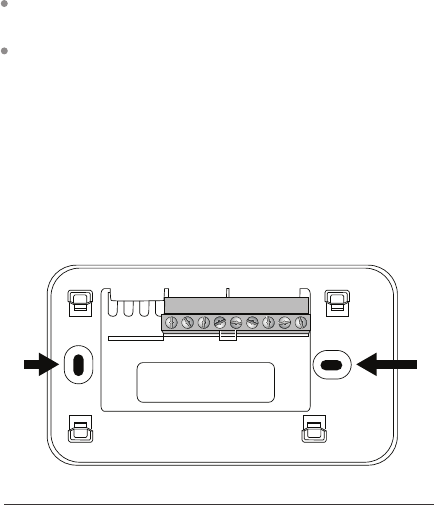
To install the thermostat:
1. Gently separate the backplate from the thermostat.
2. Place the thermostat backplate on the wall. Make sure that
any existing wires can be inserted through the opening for the
wiring.
3. Using the backplate as a template, mark the location of the
mounting holes on the wall as shown below.
4. Move the backplate out of the way and make holes where
indicated in step 3. The mounting holes can accommodate a #6
pan-head screw. It is recommended to use the included fasteners
to ensure proper tting of the front housing.
5. Use the included drywall plugs (or other suitable anchors) to
ensure the thermostat can be mounted securely to the wall.
6. Fasten the backplate to the wall using the screws provided (or
other suitable screws).
Y N/C
W
O/B
GRCRHCY2
W2
AUX
The solid color indicates mounting holes
7
8
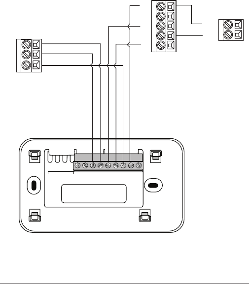
Step 4. Connect the Wiring
You need to use low-voltage cable to connect the thermostat to the HVAC
equipment. Check the wiring diagrams on pages 8 to 17 for the number of
wires required.
Note: There is a factory installed jumper between R/H and R/C. Ensure any
unused wires do not have exposed bare copper conductors.
To connect the thermostat to the equipment:
1. Connect the wires as shown in the wiring diagrams.
2. Attach the Smart Si thermostat to the backplate. Ensure that the pins on
the thermostat align with the terminal block on the backplate.
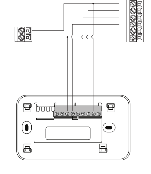
Wiring Diagrams
The following diagrams show how to connect the thermostat terminals to
various HVAC equipment.
9
YN/C
W
O/B
GRCRHCY2
W2
AUX
1-stage AC
C
24V
Y
G
R
W
C
HUM
1-stage Furnace
Smart Si Thermostat
Single stage heat/cool
10
2-stage AC
Y2
R
C
Y1
Y
G
R
W
C
HUM
1-stage Furnace
Smart Si Thermostat
YN/C
W
O/B
GRCRHCY2
W2
AUX
Single stage heat, dual stage cool
11
YN/C
W
O/B
GRCRHCY2
W2
AUX
Y1
G
W2
W1
HUM
C
R
Y2
2-stage Furnace
Smart Si Thermostat
1-stage AC
C
24V
Dual stage heat, single stage cool
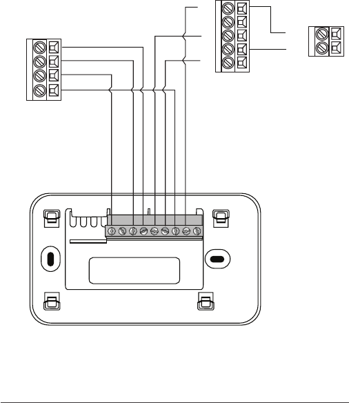
12
YN/C
W
O/B
GRCRHCY2
W2
AUX
Y1
G
W2
W1
HUM
C
R
Y2
2-stage Furnace
Smart Si Thermostat
2-stage AC
Y2
R
C
Y1
Dual stage heat, dual stage cool
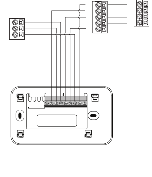
13
YN/C
W
O/B
GRCRHCY2
W2
AUX
O
W
Y/Y1
C
G
R
Air Handler
Smart Si Thermostat
1-stage Heat Pump
W2
R
Y
C
O
Single stage heat pump with auxiliary heat
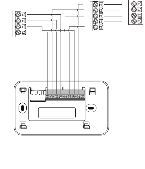
14
YN/C
W
O/B
GRCRHCY2
W2
AUX
O
W
Y/Y1
C
G
R
Air Handler
Smart Si Thermostat
2-stage Heat Pump
W2
Y1
R
Y2
C
O
Dual stage heat pump with auxiliary heat
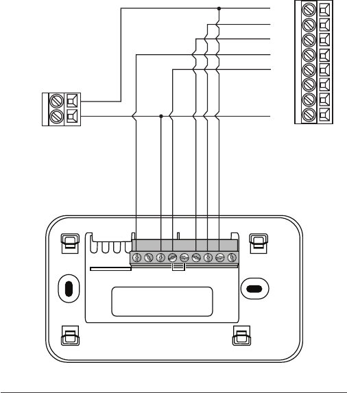
15
YN/C
W
O/B
GRCRHCY2
W2
AUX
1-stage AC
C
24V
Boiler
C
R
W
Y1
R
C
Y2
G
Air Handler
Smart Si Thermostat
Boiler with air handler and single-stage cool
* Remove RH/RC factory jumper
C terminal to be connected to heating
transformer common
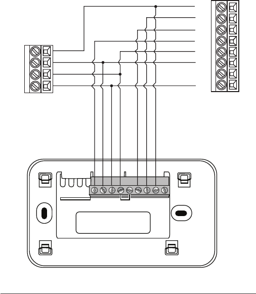
16
YN/C
W
O/B
GRCRHCY2
W2
AUX
1-stage AC
C
24V
2-stage Boiler
C
W2
R
W1
Y1
R
C
Y2
G
Air Handler
Smart Si Thermostat
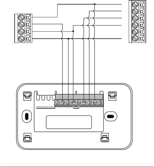
Dual stage boiler with air handler and single stage cool
* Remove RH/RC factory jumper
C terminal to be connected to heating
transformer common
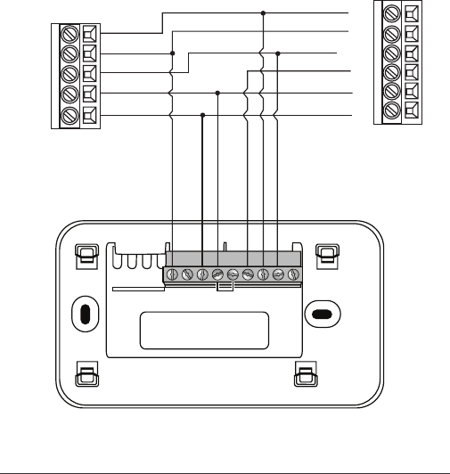
17
YN/C
W
O/B
GRCRHCY2
W2
AUX
2-stage AC
C
Boiler
C
W
R
Y1
RR
C
Y2
Y1
Y2
G
Air Handler
Smart Si Thermostat
Single stage boiler with air handler, dual stage cool
* Remove RH/RC factory jumper
C terminal to be connected to heating
transformer common
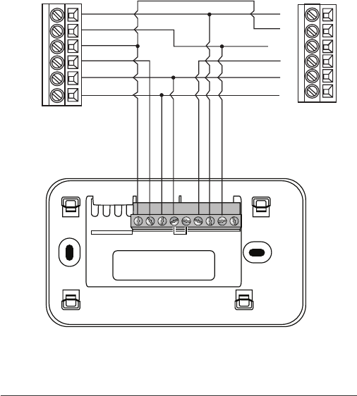
18
YN/C
W
O/B
GRCRHCY2
W2
AUX
2-stage AC
C
2-stage Boiler
C
W2
W1
R
Y1
RR
C
Y2
Y1
Y2
G
Air Handler
Smart Si Thermostat
Dual stage boiler with air handler, dual stage cool
* Remove RH/RC factory jumper
C terminal to be connected to heating
transformer common
Step 5. Power On HVAC
Equipment
After you’ve completed the wiring, you can
apply power to the heating and air conditioning
equipment. The Smart Si thermostat
receives power from the equipment and will
automatically power on.
NAVIGATING THE MENUS
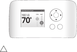
The Smart Si thermostat has an easy-to-read
color screen that displays all the information
you need to congure the thermostat. Use
the navigation buttons on the right to quickly
change the temperature, access features, and
congure settings.
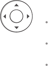
Using the Navigation Buttons
The navigation buttons located on the right of
the Smart Si thermostat let you select options
and control the Smart Si thermostat.
▲ (up) On the Home screen, press ▲ to
increase the temperature set point by 1°F
(0.5°C). For menus, press ▲ to move up.
▼ (down) On the Home screen, press ▼ to
decrease the temperature set point by 1°F
(0.5°C). For menus, press ▼ to move down.
◀(left) On the Home screen, if Auto mode is
enabled, press ◀ to switch between heat and
cool set points. For menus, press ◀ to go back
to the previous screen.
OK
19
▶(right) On the Home screen, if Auto mode
is enabled, press ▶ to switch between heat
and cool set points. For menus, press ▶ to
choose the currently highlighted option.
OK On a menu screen, press OK to choose
the currently highlighted option. If a
conguration option is selected, pressing OK
will keep its new value and return back to the
previous screen.
MENU Pressing MENU displays a list of all
available options. If a menu is currently
displayed, pressing MENU will cancel any
unsaved changes and return to the Home
screen.
BACK On a menu screen, press BACK to go
back to the previous screen.
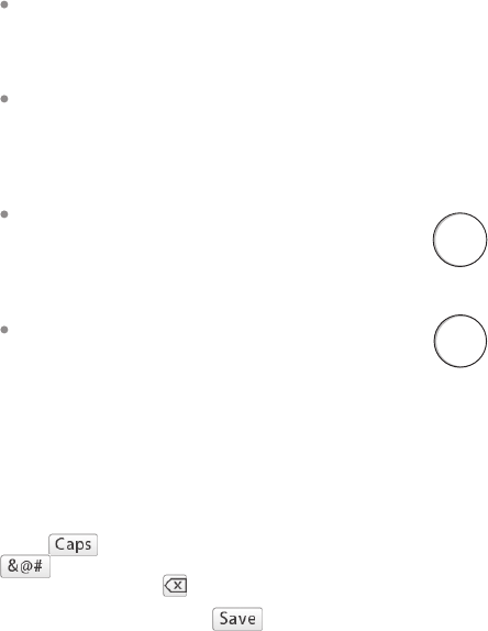
On-Screen Keyboard
If you need to type in any information, an on-
screen keyboard will appear. To enter a letter or
number, move to the character by pressing the
arrow keys and then press OK to select it.
Select to enter capital letters; select
to enter commonly used symbols. If you
make a mistake, press to delete the text .
To keep your changes, select . To cancel
your changes, press BACK.
MENU
BACK
20

CONFIGURING THE SMART
Si THERMOSTAT
The rst step after installing the Smart Si
thermostat is to congure the settings for
the various devices (such as a furnace or air
conditioner) that are being connected.
Equipment
The Equipment settings let you congure the
devices connected to the thermostat.
Heat Pump
This section lets you congure a heat pump with
up to 2 heat/2 cool stages plus an auxiliary heat
source.
Geothermal heat pump Select Yes if you are
using a geothermal heat pump. This helps the
thermostat determine optimum performance
and default settings. If you select No, the
system will optimize the settings for an air-to-
air heat pump.
OB energize on cool If you choose Yes, the
reversing valve output (O/B terminal) will
activate when there is a call for cooling. If you
select No, the relay will activate when there is
call for heat.
Min Cycle O Time Congures the minimum
compressor o time between cycles (240 to
900 seconds).
Min Outdoor Temp Disables the compressor
when the outside air temperature reaches the
congured minimum setting. This performs
two functions. It prevents the compressor
To congure the
equipment settings:
From the Home screen,
press MENU.
Select Settings ▶
Installation Settings.
Select Equipment.
Congure the devices
connected to the
thermostat.
21

from running when the outdoor temperature
is too low, thus resulting in damage to the
compressor. You can also set this value to
determine when you want the auxiliary heat
(if installed) to engage to help meet the
set temperature. The temperature range is
adjustable from 0 to 65 °F (–17.8 to 18.3 °C) or
can be completely disabled. Note: You need
an internet connection for this feature to
operate properly.
Allow HP with Aux Heat If you select Yes
and there is a source of auxiliary heat, it will
turn on in addition to the heat pump. The
heat pump will be energized for the rst 30
minutes. If, after 30 minutes, the set point
has not been met, the auxiliary heat will be
energized to assist the heat pump in meeting
the load.
If you select No, the heat pump will be
energized for up to 2 hours. If after 2 hours the
set point has not been met, the thermostat
will shutdown the heat pump and energize
the auxiliary heat to meet the set point. This
option should also be used for installation
where the heat pump evaporator coil is
downstream from the source of auxiliary heat.
This setting is only available the Comp to
Aux Temp Delta and Comp to Aux Runtime
settings are both set to Auto (default)
Furnace
Allows you to enable and congure up to a
2-stage conventional heat source. If you have
selected a heat pump as your primary source,
this feature allows you to congure the 1st stage
of auxiliary heat connected to the system.
Furnace Type Allows you to congure the
type of furnace. This helps the thermostat 22

optimize its algorithms based on the type
of fuel and typical characteristics of the
chosen system. Choose the option that
best represents the type of heating system
installed.
Heat Fan Control Congures the furnace fan
to be controlled by the Smart Si thermostat or
the HVAC system during heat cycles. Normally
the HVAC system controls the fan during heat
cycles.
Air Conditioner
Congures up to 2 stages of air conditioning. If
you require a second stage, you must enable the
Y2 relay.
Thresholds
This section congures the temperature and
time thresholds associated with the heating and
cooling equipment.
You must congure the Equipment settings
(page 10) before setting the thresholds. Only the
applicable threshold settings will be displayed
(i.e. if no air conditioner is congured, you will
not see the options related to air conditioners).
Allow Auto Heat/Cool
Enabling this option allows the user to select
auto change-over as a system mode.
Heat/Cool Min Delta
The minimum dierence between the heat
mode set temperature and the cool mode set
temperature when the system mode is in auto
change-over. The delta is adjustable from 2 to 10
°F (1.1 to 5.5 °C). The default value is 5 °F (2.8 °C).
To congure threshold
settings:
From the Home screen,
press MENU.
Select Settings ▶
Installation Settings.
Select Thresholds.
Congure the
temperature threshold
settings.
23
Compressor Settings
Min Cycle O Time Congures the
compressor o time between cycles. This
ensures the compressor does not short cycle
(which could aect the operating life of the
system). This time is adjustable from 240–900
seconds.
Min Outdoor Temp Congures the minimum
outside air temperature at which the
compressor will be disabled. This performs
two functions. It prevents the compressor
from running when the outdoor temperature
is too low, thus resulting in damage to the
compressor. You can also set this value to
determine when you want the auxiliary heat
(if installed) to engage to help meet the
set temperature. The temperature range is
adjustable from 0 to 65 °F (–17.8 to 18.3 °C) or
can be completely disabled. Note: You need
an internet connection for this feature to
operate properly.
Aux Heat Settings
Max Outdoor Temperature Congures the
maximum outdoor temperature threshold.
Above this level, the auxiliary heat will not
be activated. The temperature is adjustable
from 0 to 80 °F (26.5 °C) in increments of 0.5°F
(0.5°C). The default value is 70°F (21°C).
Common Heat/Cool Settings
Heat Dierential Temp The minimum
dierence between the current temperature
and set temperature before the system calls
for heat. A smaller dierence means shorter
cycle times, whereas a larger dierence results
in longer cycle times. The temperature range
24

is adjustable form 0 to 3 °F (-17.5 to 26.5 °C) in
0.5°F (0.5°C) increments.
Heat Dissipation Time The amount of time
the fan will run after the heat set point has
been reached and the call for heat has been
turned o. Running the fan for a period of
time allows for any heated air left in the ducts
to circulate throughout the home. The time is
adjustable from 0 to 900 seconds. The default
value is 30 seconds.
Cool Dierential Temp The minimum
dierence between the current temperature
and set temperature before the system calls
for cool. A smaller dierence means shorter
cycle times, whereas a larger dierence results
in longer cycle times. The temperature range
is adjustable from 0 to 3 °F (0.3 to 1.7 °C) in
0.5°F (0.3°C) increments.
Cool Dissipation Time The amount of time
the fan will run after the cool has been turned
o. Running the fan for a period of time allows
for any cooled air left in the ducts to circulate
throughout the home. The time is adjustable
from 0 to 900 seconds. The default value is 30
seconds.
Advanced Settings
These options customize how long each stage
will run before the next stage turns on. You may
also program when a particular stage is turned
on based on the temperature delta between the
set temperature and the current temperature.
Reverse Staging If enabled, the thermostat
will cycle down from the higher stages so
that as it approaches set point it will only be
running in stage 1. The HVAC equipment will
25

start in stage 1. As the stage 1 temperature
delta is exceeded, the second stage will
engage. Once the equipment has brought
the current temperature back to within the
heat or cool dierential setting, stage 2 will
disengage and stage 1 will remain running
until the set point is meet.
Stage 2 Temp Delta The minimum dierence
between the current temperature and the set
temperature that will activate the auxiliary
heat (regardless if the maximum run time of
the previous stage was reached). Options are
Auto (default) and 1 to 10 °F (0.6 to 5.6 °C).
Stage 1 Max Runtime The maximum amount
of time stage 1 will run before engaging the
next stage. Options are Auto (default) and 10
to 120 minutes.
Comp to Aux Temp Delta The maximum
amount of time this stage will run before
engaging the next stage. Options are Auto
(default) and 1 to 10 °F (0.6 to 5.6 °C).
Comp to Aux Runtime The minimum
dierence between the current temperature
and the set temperature that will activate this
stage (regardless if the maximum run time of
the previous stage was reached). Options are
Auto (default), Disabled, and 1 to 10 °F (0.6 to
5.6°C).
Cool Min On Time Sets the minimum
equipment run time in cool mode: 1 to 20 min
(default is 5 min).
Heat Min On Time Sets the minimum
equipment run time in heat mode: 1 to 20 min
(default is 5 min).
26

Temp Correction
Lets you program an oset between the real
temperature at thermostat and the displayed
temperature. If you nd that the temperature
where the thermostat is located does not
represent the room temperature, change the
oset to compensate for the dierence. The
correct temperature is adjustable from +/- 10°F
in 0.5°F (0.3°C) increments.
Installer Code
To prevent accidental modications to the
installation settings, you can enable a 4-digit
installer code. This code is pre-programmed to
3262.
Test Equipment
These options let you test the wiring and
connections of the devices connected to the
thermostat by turning them on or o.
The equipment will turn o when you exit the
menu.
Warning: Compressor protection and
minimum run-time features are not
enforced while in this mode.
To test the equipment:
From the Home screen,
press MENU.
Select Settings ▶
Installation Settings.
Select Test Equipment.
Select OK.
Test the equipment
connected to the
thermostat by turning each
component on and o.
!
Reset HVAC Equipment Settings
You can quickly restore all HVAC equipment
settings on the Smart Si thermostat back to their
factory defaults. Any user setting (not related to
the equipment installed) will remain unchanged.
If you need to reset the entire thermostat back
to its original factory default settings, including
user settings and registration, select Reset All
Settings instead.
Performing a Hardware Reset
In rare circumstances, static electricity or power
surges may interrupt the operation of the
thermostat, forcing a hardware reset.
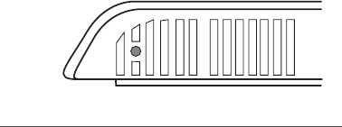
Rebooting the Smart Si
Thermostat
You can reboot the Smart Si thermostat by
pressing the physical hardware reset button,
located through an opening in the bottom left
corner of the Smart Si thermostat. Rebooting
will not alter programming or conguration
options.
To reset the Smart Si
thermostat:
From the Home screen,
press MENU.
Select Settings ▶Reset.
Select HVAC Equipment
Settings.
Select Ye s.
Reset button
27
Reset HVAC Equipment Settings
You can quickly restore all HVAC equipment
settings on the Smart Si thermostat back to their
factory defaults. Any user setting (not related to
the equipment installed) will remain unchanged.
If you need to reset the entire thermostat back
to its original factory default settings, including
user settings and registration, select Reset All
Settings instead.
Performing a Hardware Reset
In rare circumstances, static electricity or power
surges may interrupt the operation of the
thermostat, forcing a hardware reset.
Rebooting the Smart Si
Thermostat
You can reboot the Smart Si thermostat by
pressing the physical hardware reset button,
located through an opening in the bottom left
corner of the Smart Si thermostat. Rebooting
will not alter programming or conguration
options.
To reset the Smart Si
thermostat:
From the Home screen,
press MENU.
Select Settings ▶ Reset.
Select HVAC Equipment
Settings.
Select Ye s.
Reset button
28
Conguring Reminders and
Alerts
The Reminders and Alerts list displays the
reminders and alerts described below.
HVAC Service
The HVAC Service (maintenance) reminder
generates an alert telling the homeowner that
regularly scheduled maintenance is required.
This alert, along with technician contact
information can be displayed on the screen.
If homeowners register their thermostats, the
reminders will be emailed to them and be
displayed in the web portal.
You can set the Last Service date, turn the
Reminder On or O, and to set the Frequency of
the maintenance interval in months.
Furnace Filter
Generates an alert for cleaning or changing
the lter. You can set the Last Filter Change
date, turn the Reminder On or O, and set the
Frequency of the maintenance interval.
UV Lamp
Sets the reminder period for cleaning or
replacing the UV lamp. You can set the Last
Lamp Change date, turn the Reminder On or
O, and set the Frequency of the maintenance
interval.
To congure Reminders
and Alerts
From the Home screen,
press MENU.
Select Reminders and
Alerts.
Congure the Reminder
and Alert settings as
required.
29

Alerts
The Smart Si thermostat can generate alerts if the
temperature in the home goes over or under a pre-
programmed level. This protects the home from
damage due to freezing and/or excessive heat.
This alert, along with optional technician contact
information will be displayed on the screen. If the
homeowner registers the thermostat, the alert will
be emailed to them and be displayed in the web
portal.
Low Temp Alert Sets the temperature at which the
thermostat will generate a Low Temperature Alert.
The range can be:
O – no alert will be generated.
Set temperature range of 35 to 68 °F (1.5 to 20
°C).
High Temp Alert Sets the temperature at which
the thermostat will generate a High Temperature
Alert. The range can be:
O – no alert will be generated.
Set temperature range of 60 to 104 °F (15.5 to
40 °C).
Display Alerts on Thermostat
Select No if you do not want any of the alerts to be
displayed on the Smart Si thermostat screen. Alerts
will continue to be displayed on the web portal and
sent via email.
Enable Heating/Cooling Alerts
Select No to disable alerts for heat/cool error
conditions. If disabled, alerts indicating that the
system failed to heat or cool will not be appear in
the screen, web portal, or emails.
30
List of Alerts
Below is a complete list of alerts. Depending
on your conguration, some of these may not
apply.
Furnace Air
Filter
UV Lamp
Low Temp Alert
High Temp Alert
Heat Not
Responding
Cool Not
Responding
Maintenance
Reminder
Auxiliary Heat Run
Time
Auxiliary Outdoor
Temperature
Furnace lter needs to be
cleaned or changed.
UV lamp needs to be changed.
Temperature in the home is too
low.
Temperature in the home is too
high.
The system has failed to heat
the home.
The system has failed to cool the
home.
HVAC system due for regular
maintenance.
Auxiliary heat source is running
too often.
Your Smart Si thermostat
auxiliary heat has been called
to run when the outdoor
temperature exceeds the
programmed set point.
31
3-YEAR LIMITED WARRANTY
ecobee warrants that for a period of three (3) years from the date of purchase by the
consumer (“Customer”), the ecobee Smart Si thermostat (the “Product”) shall be free
of defects in materials and workmanship under normal use and service. During the
warranty period, ecobee shall, at its option, repair or replace any defective Products, at
no charge. Any replacement and/or repaired device are warranted for the remainder of
the original warranty or ninety (90) days, whichever is longer.
If the product is defective, call Customer Service at 1-877-932-6233. ecobee will make
the determination whether a replacement product can be sent to you or whether the
product should be returned to the following address: ecobee Customer Service, 250
University Avenue, Suite 400, Toronto, ON M5H 3E5, Canada. In the event of a failure
of a Product, Customer may:
(a) if Customer did not purchase the Product directly from ecobee, contact the third
party contractor from whom the Product was purchased to obtain an equivalent
replacement product, provided the contractor determines that the returned Product is
defective and Customer is otherwise eligible to receive a replacement product;
(b) contact ecobee directly for service assistance at 1-877-932-6233 and ecobee will
make the determination whether an advance equivalent replacement Product can
be sent to Customer with return shipping supplies (in which case a hold shall be put
on Customer’s credit card for the value of the replacement Product until ecobee has
received the defective Product). Product should be returned to the following
address: ecobee Customer Service, 250 University Avenue, Suite 400, Toronto, ON
M5H 3E5, Canada. If the returned Product is found by ecobee to be defective and
Customer is otherwise eligible to receive a replacement product, no amount shall
be charged to Customer’s credit card; or
(c) ship the defective Product directly to ecobee, in which case Customer shall contact
ecobee directly at 1-877-932-6233, so ecobee can make the required shipping
arrangements. Upon receipt of the defective Product, ecobee will ship an equivalent
replacement product to Customer, provided the returned Product is found by ecobee to
be defective and Customer is otherwise eligible to receive a replacement product.
This warranty does not cover removal or reinstallation costs and shall not apply if the
damages were found to be caused by something other than defects in materials or
workmanship, including without limitation, if the Product:
was operated/stored in abnormal use or maintenance conditions;
was subject to abuse, neglect, electrical fault, improper handling, accident or acts
32
of nature;
was not installed by a licensed Heating Ventilating and Air Conditioning (HVAC)
contractor; or
was installed improperly.
ecobee’s sole responsibility shall be to repair or replace the Product within the terms
stated above. ECOBEE SHALL NOT BE LIABLE FOR ANY LOSS OR DAMAGE OF ANY KIND,
INCLUDING ANY SPECIAL, INCIDENTAL OR CONSEQUENTIAL DAMAGES RESULTING,
DIRECTLY OR INDIRECTLY, FROM ANY BREACH OF ANY WARRANTY, EXPRESS OR
IMPLIED, OR ANY OTHER FAILURE OF THIS PRODUCT. Some US states and Canadian
provinces do not allow the exclusion or limitation of incidental or consequential
damages, so the above limitation or exclusion may not apply to you.
limited to repair and replacement as set forth in this warranty statement. All express
and implied warranties for the product, including but not limited to any implied
limited to the three-year duration of this limited warranty. No warranties, whether
express or implied, will apply after the limited warranty period has expired. Some
US states and Canadian provinces do not allow limitations on how long an implied
warranty lasts, so this limitation may not apply.
ecobee neither assumes responsibility for nor authorizes any other person purporting
to act on its behalf to modify or to change this warranty, nor to assume for it any other
warranty or liability concerning this product.
from jurisdiction to jurisdiction. If you have any questions regarding this warranty,
please write ecobee Customer Service, 250 University Avenue, Suite 400, Toronto, ON
M5H 3E5, Canada.
Approvals
This product was designed and built in accordance to RoHS directive 2002/95/EC and
contains no hazardous substances as defined by this directive.
FCC Compliance Statement
This equipment has been tested and found to comply with the limits for a Class B
digital device, pursuant to part 15 of the FCC Rules. These limits are designed to
provide reasonable protection against harmful interference in a residential installation.
This equipment generates, uses and can radiate radio frequency energy and, if not
installed and used in accordance with the instructions, may cause harmful interference
to radio communications. However, there is no guarantee that interference will not
occur in a particular installation. If this equipment does cause harmful interference to
radio or television reception, which can be determined by turning the equipment off
33
34
and on, the user is encouraged to try to correct the interference by one or more of the
following measures:
• Reorient or relocate the receiving antenna.
• Increase the separation between the equipment and receiver.
• Connect the equipment into an outlet on a circuit different from that to which the
receiver is connected.
• Consult the dealer or an experienced radio/TV technician for help.
This device complies with part 15 of FCC rules. Operation is subject to the following two
conditions:
1. This device may not cause harmful interference.
2. This device must accept any interference received, including interference that may
cause undesired operation.
Change or modifications that are not expressly approved by the manufacturer could
void the user’s authority to operate the equipment.
RF Exposure Information
This equipment complies with FCC radiation exposure limits set forth for an
uncontrolled environment. In order to avoid the possibility of exceeding the FCC radio
frequency exposure limits, human proximity to the antenna shall not be less than 20cm
during normal operation.
Industry Canada (IC)
Compliance Notice:
This device complies with Industry Canada license-exempt RSS standard(s).
Operation is subject to the following two conditions:
1. This device may not cause interference, and
2. This device must accept any interference, including interference that may cause
undesired operation of the device.
Le présent appareil est conforme aux CNR d’Industrie Canada applicable aux appareils
radio exempts de licence. L’exploitation est autorisée aux deux conditions suivantes:
1. l’appareil ne doit pas produire de brouillage, et
2. l’utilisateur de l’appareil doit accepter tout brouillage radioélectrique subi, même si le
brouillage est susceptible d’en compromettre le fonctionnement.
This Class B digital apparatus complies with Canadian ICES-003.
Cet appareil numérique de la classe B est conforme à la norme NMB-003 du Canada.
FCC ID: WR9EBSTATSI01 IC: 7981A-EBSTATSI01
Warning: Changes or modifications not expressly approved by ecobee Inc. could void
the user’s authority to operate the equipment.
RF Exposure Statement:
This equipment complies with IC RSS-102 radiation exposure limits set forth for an
uncontrolled environment. This transmitter must be installed to provide a separation
distance of at least 20 cm from all persons and must not be collocated or operating in
conjunction with any other antenna or transmitter.
Cet équipement est conforme avec IC RSS-102 des limites d'exposition aux
rayonnements définies pour un environnement non contrôlé. Cet émetteur doit être
installé à au moins 20 cm de toute personne et ne doit pas être colocalisé ou
fonctionner en association avec une autre antenne ou émetteur.
35

© 2014 ecobee
250 University Avenue, Suite 400
Toronto, ON M5H 3E5, Canada
ecobee is a registered trademark of ecobee inc.
All rights reserved.
We’re here to help
Connect with us online
support@ecobee.com | 1.877.932.6233
@ecobee facebook.com/ecobee