f u n k e AVIONICS FSG90 VHF/AM aviation analogue voice COMM transceiver User Manual FSG90F Installation Operation 11 2000
f.u.n.k.e. AVIONICS GmbH VHF/AM aviation analogue voice COMM transceiver FSG90F Installation Operation 11 2000
Contents
- 1. FSG 90EPC Portable case manual part one
- 2. FSG 90EPC Portable case manual part two
- 3. Frontpanel Module without case part one
- 4. Frontpanel Module without case part two
- 5. Desktop case with front module part one
- 6. Desktop case with front module part two
- 7. FSG 90F ops manual part one
- 8. FSG 90 Maintenance Manual part one
- 9. FSG 90 Maintenance Manual part two
FSG 90F ops manual part one

6 Watt FSG 90F
10 Watt FSG 90F-H1
No. LBA.O.10.911/98 JTSO
DFS-No.: B-7850/97
6 Watt – 10 Watt Dual Mode
VHF/AM AIRBAND TRANSCEIVERS
118.000 ... 136.975 MHz
8.33 kHz/25 kHz or ‘25 kHz only’ channel spacing
Installation & Operation
applies for FSG 90F article no. F10194
applies for FSG 90F-H1 article no. F10306
Before installing and operating the transceiver,
read this manual thoroughly, please!
Please observe the Safety Information!
Keep for further use!
Document No.: IM 034.00
Article-No.: D10033
Date of Issue November 2000
Avionics Division
Erpftinger Strasse 36 « D-86899 Landsberg « GERMANY
Telephone +49 8191/ 3351-0 « Fax +49 8191/ 3351-49
e-mail: firma@dittel.com « Internet: http://www.dittel.com

FSG 90F System
Airband Transceiver
Page 2November 2000
W. Dittel GmbH
Warranty - Copyright - Service
Warranty
The details and data in this operator's manual correspond to the respective
state of technology on the day of printing. We reserve our right to change
without prior notice due to new technological design or corresponding new
production technology.
Walter Dittel GmbH takes no guarantee for these documents with respect to
application and interpretation.
Walter Dittel GmbH ("Warrantor") warrants to the purchaser of new radio
equipment of the warrantor's manufacture that such equipment shall be free
from defects in material and workmanship for a period of 24 month from the
date of delivery. Equipment and accessory items not manufactured by the
Warrantor carry the standard warranty (12 month) of the manufacturer
thereof.
This warranty does not cover equipment which has been
1. damaged or not maintained as reasonable and necessary,
2. modified in any way,
3. improperly installed,
4. repaired by someone other than the warrantor or an authorized
warranty avionics shop, or
5. used in a manner or purpose for which the equipment was not
intended.
This warranty shall not extend to incidental or consequential damages arising
from operation of the equipment or from any claimed breach of this warranty.
Copyright 1998 Walter Dittel GmbH
All rights reserved. This document contains proprietary information and such
information may not be disclosed to others for any purpose nor used for
manufacturing purposes without prior written permission of the manufacturer
Walter Dittel GmbH, Luftfahrtgeraetebau, D-86899 Landsberg am Lech,
Germany.
In this document no mention is made of patents, trademark rights, or other
proprietary rights which may attach to certain words or entries. The absence
of such mention, however, in no way implies that the words or entries in
question are exempt from such rights.
Service
The information in this Operator's Manual does not profess to include all the
details of design, production, or variation of the equipment, or to cover all the
possible contingencies which may arise during operation or maintenance.
Should any unusual problem arise or further information be desired, please
contact the Walter Dittel GmbH Service Department, Erpftinger Strasse 36,
D-86899 Landsberg am Lech, Germany.
Subject to technical changes Printed in Germany 14.09.01

FSG 90F System
Table of Content
November 2000 Page 3
W. Dittel GmbH
Table of Content
Page
Warranty - Copyright - Service..................................................................................... 2
Table of Content............................................................................................................ 3
List of Illustrations........................................................................................................ 5
Abbreviations................................................................................................................ 6
Section 1, Safety Information....................................................................................... 7
1.1 Used Symbols.................................................................................................... 8
Section 2, General Description.................................................................................... 9
2.1 Introduction ........................................................................................................ 9
2.2 Models of the FSG 90F System .......................................................................... 9
2.3 Application.......................................................................................................... 9
2.4 Brief Description............................................................................................... 10
2.5 System and Type Approval Information ........................................................... 12
2.6 Operating License............................................................................................ 13
2.7 Equipment supplied.......................................................................................... 13
2.8 Optional Accessories ....................................................................................... 14
2.9 Accessories required, but not supplied ............................................................ 15
2.10 Microphone hints.............................................................................................. 15
Section 3, Installation................................................................................................. 17
3.1 General ............................................................................................................ 17
3.2 Unpacking and Inspecting Equipment.............................................................. 17
3.3 Pre-installation Test ......................................................................................... 17
3.3.1 Particular Remarks to FSG 90F(X) transmitter modulation .................................... 18
3.4 Mechanical Installation..................................................................................... 20
3.4.1 Transceiver installation ......................................................................................... 20
3.4.2 Compass deviation ............................................................................................... 20
3.4.3 Antenna installation............................................................................................... 23
3.5 Airborne wiring ................................................................................................. 24
3.5.1 General recommendations.................................................................................... 24
3.5.2 Microphone Connection ........................................................................................ 28
3.5.3 Intercom (IC)......................................................................................................... 28
3.5.4 Loudspeaker / Headset interconnection................................................................ 29
3.5.5 AF External Operation .......................................................................................... 29
3.5.6 Lighting the Frequency Display............................................................................. 29
3.5.7 Connection to a 28 Vdc airborne system .............................................................. 30
3.6 Post-installation Check..................................................................................... 30
3.6.1 Testing on the Ground with Engine Off................................................................. 30
3.6.2 Ground checks with engine running...................................................................... 30

FSG 90F System
Table of Content
Page 4November 2000
W. Dittel GmbH
Table of Content
Page
Section 4, Functional Description ............................................................................. 33
4.1 Introduction....................................................................................................... 33
4.2 Operator's Controls .......................................................................................... 33
4.3 Frequency Display, 5-digit or 6-digit Liquid Crystal Display (LCD). .................. 36
4.4 Connectors at rear side.................................................................................... 37
Section 5, Set-up Procedure ...................................................................................... 39
5.1 Calling SET-UP without password.................................................................... 40
5.2 Calling SET-UP with password......................................................................... 40
5.3 Interrupt the SET-UP procedure....................................................................... 41
5.4 SET-UP procedure........................................................................................... 41
5.4.1 Adjusting the automatic squelch threshold ............................................................41
5.4.2 Adjusting the microphone sensitivity (Dynamic or amplified/carbon microphones) 41
5.4.3 Adjusting the Intercom volume ..............................................................................42
5.4.4 Adjusting the Sidetone volume ..............................................................................43
5.4.5 Adjusting the headset volume ...............................................................................43
5.4.6 Selecting '25 kHz only' or combined 8.33/25 kHz channel spacing........................44
5.4.7 Deleting occupied channel memories....................................................................44
5.4.8 Selecting AF EXTERNAL (ON/OFF) .....................................................................45
5.4.9 Selecting 'CHANNEL MODE ONLY' or 'NO RESTRICTION' .................................45
5.4.10 Selecting 'Transmitter Blocking' during receive (ON/OFF).....................................45
5.4.11 Service (ON/OFF) .................................................................................................46
5.4.12 Optional module (ON/OFF) ...................................................................................46
5.4.13 Entering a password..............................................................................................46
5.4.14 Reset.....................................................................................................................47
Section 6, Operating Instruction................................................................................ 49
6.1 Introduction....................................................................................................... 49
6.2 Turning ON - Selecting Frequency/Channel Name - Volume........................... 49
6.3 Receive (Listen) Operation............................................................................... 50
6.4 Transmit (Talk) Operation ................................................................................ 51
6.5 Storing a new Frequency/Channel Name......................................................... 52
6.6 Recall of stored Frequency/Channel Name...................................................... 52
6.7 Squelch (SQ) Operation................................................................................... 52
6.8 Intercom ........................................................................................................... 53
6.9 AF External....................................................................................................... 53
6.10 Lighting............................................................................................................. 53
6.11 Turning OFF..................................................................................................... 53
6.12 Checking the A/C onboard supply.................................................................... 54
6.13 Operating times with radio supplied from 12 V battery only ............................. 55
6.14 Emergency Operation ...................................................................................... 55

FSG 90F System
Table of Content
November 2000 Page 5
W. Dittel GmbH
Table of Content
Page
Appendix A, Technical Summary .............................................................................. 57
A1 General ............................................................................................................ 57
A2 Dimensions, Weight, Fuses ............................................................................. 58
A3 Approvals ......................................................................................................... 58
A4 Receiver Characteristics .................................................................................. 59
A5 Transmitter Characteristics .............................................................................. 61
Appendix B, Environmental Performance Classification........................................ 62
Appendix C, ICAO Frequency-Channel pairing plan for combined
8.33 kHz /25 kHz Operation ................................................................. 63
Appendix D, Certificates............................................................................................. 64
List of Illustrations
Fig. Page
3-1 Test Setup, Envelope Detector................................................................................... 19
3-2 Deviation of a compass by an operating FSG 90F(X), dependent on
the distance between compass center and contour of transceiver.............................. 20
3-3 FSG 90F(X), Dimensions, Installation Drawing............................................................ 21
3-4 FSG 90F(X), Installation of the Fastener Strips ........................................................... 22
3-5 Hook-up Diagram using wire harness F10189, 1-2 dynamic microphone(s)............... 25
3-6 Hook-up Diagram using wire harness F10190,
1-2 dynamic microphone(s) and Intercom .................................................................. 26
3-7 Hook-up Diagram, 2 amplified/carbon microphones and Intercom ............................. 27
4-1 Operator's Controls and Indicators............................................................................. 33

FSG 90F System
Abbreviations
Page 6November 2000
W. Dittel GmbH
Abbreviations
A/C Aircraft
A/N Article Number (DITTEL)
AGC Automatic Gain Control
Ah Ampere hour
AM Amplitude Modulation
ANT Antenna
Ass'y Assembly
AWG American Wire Gauge
ccw Counterclockwise (turn left ?)
CH Channel
CTS Ready-to-Transmit
cw Clockwise (turn right ?)
dB Decibel
dia. Diameter
EMF Electromotive Force (voltage of
an open circuit)
F/CH Frequency/Channel
FL Flight Level
gAcceleration due to gravity
GND Ground
HI High Power
Hz Hertz
ICAO International Civil Aviation Organization
IF Intermediate Frequency
kHz Kilohertz
LCD Liquid Crystal Display
LED Light Emitting Diode
LO Low Power
LOS Line-Of-Sight
mModulation
mA Milliamperes
MD Mode
MHz Megahertz
MIC Microphone
mW Milliwatt
NM Nautical miles
nW Nanowatt (10-9)
PEP Peak Envelope Power
PLL Phase-Locked Loop
ppm parts per million
PTT Push-To-Talk
pW Picowatt (10-12)
PWR Power
RF Radio Frequency
rms Effective value (root mean
square)
RTS Invitation to send
RX Receive
RxD Receive data
S+N/N Signal-to-Noise Ratio
SINAD Ratio: Signal noise distortion
noise distortion
+ +
+
SPKR Loudspeaker
SQ Squelch
STBY Standby
STO Store
SWR Standing-Wave Ratio
TOT Time out timer
TX Transmit
TxD Transmit data
VCO Voltage-Controlled Oscillator
Vdc Volts, direct current
VHF Very-High Frequency
VOL Volume
VSWR Voltage Standing-Wave Ratio
WWatt
OOhm
°C Degrees Centigrade
°F Degrees Fahrenheit

FSG 90F System
1. Safety Information
November 2000 Page 7
W. Dittel GmbH
Section 1 Safety Information
Every radio, when transmitting, radiates energy into the atmosphere that may, under
certain conditions, cause the generation of sparks. All users of our radios should be
aware of the following warning:
Do not operate this radio in an explosive atmosphere (petroleum fuels,
solvents, dust, etc.)!
During normal use, the radio will subject you to radio frequency energy substantially
below the level where any kind of harm is reported.
TO ENSURE PERSONAL SAFETY, please observe the following simple rules:
• DO NOT transmit when the antenna is very close to, or touching, exposed parts of the
body, especially the face and eyes.
• DO NOT transmit on a busy channel.
• DO NOT press the transmit (PTT) key when not actually desiring to transmit.
• DO NOT transmit in closed aircraft or vehicles with the antenna (or part of it) inside the
cabin. This may cause malfunction of the avionics or trigger the airbag! Always operate
the radio FSG 90F(X) with a suitable outside / external antenna! Assure appropriate
lightning protection where elevated outdoor antennas are used.
• DO NOT operate the radio whilst driving. It should also be noticed that the use of a
hand held microphone while driving could constitute an offence under the Road Traffic
Regulations in certain countries.
• DO NOT allow children to play with any radio equipment containing a transmitter.
• DO NOT call radio’s SET-UP in flight or whilst driving a vehicle. Transmit and receive
are partially disabled!
• After each SET-UP check all settings of the radio and cockpit instruments for correct
function before the next flight or application!
• Always switch OFF the radio first when installing the unit into vehicles or aircraft when
removing from it!
• Always switch OFF the radio first when starting an engine or vehicle!
• When operating the FSG 90F(X) on a 24 Vdc source a suitable Voltage Converter
24 Vdc/12 Vdc of at least 4 Amps must be used!
• The FSG 90F(X) may be used exclusively for communication on the airband
frequencies.
• Unauthorized modifications and changes of the system are forbidden.
• When replacing defective parts use only original spare parts or standard parts
recommended by the manufacturer!
• In aircraft or vehicles a suitable noise canceling microphone or headset for aircraft
radios shall be used.
• A backup microphone should always be carried during any flight. Even new
microphones can fail.
• Volume is very important. Increasing speaking levels while the lips are facing the
microphone, but not straining or pushing to yelling levels will increase clarity.

FSG 90F System
1. Safety Information
Page 8November 2000
W. Dittel GmbH
• Prior to any flight verify proper FSG 90F(X) functions by means of a short
communications test. It has to be taken into account that with a faulty antenna or
cable this COM test may absolutely turn out positive at the airfield or in short distance
to the ground station. But at distances of 2 to 6 miles a faulty antenna and/or cable
will cause communication breakdown!
• Push-to-Talk keys may stick occasionally. Therefore, observe while transmitting the
transmit (TX) symbol at the FSG 90F(X) display. This TX symbol must disappear
when releasing the PTT key. After 2 minutes continuous TX the built-in transmit time
out timer disables the transmitter in order to avoid continuous channel blocking.
Then, the whole display warns by continuous flashing. Refer to appropriate hints in
this manual.
• Replace blown fuse only against correct type with specified nominal value.
Investigate the cause.
1.1 Used Symbols
In this manual the following symbols are used:
DANGER!
describes an immediate threatening danger! Failing to observe the note
may cause death or heavy injuries!
CAUTION!
describes a special note for operation. Failing to observe the note may
cause damage of the transceiver and/or stored data may be deleted (SET-
UP or user programmed memory)!
IMPORTANT!
describes explanations and other useful hints. Failing to observe the note
may cause degraded performance and/or unsatisfying operation!

FSG 90F System
2. General Description
November 2000 Page 9
W. Dittel GmbH
Section 2 General Description
2.1 Introduction
This installation and operating manual IM 034.00 contains instructions and descriptions
for application, installation, presetting operation and testing, as well as interconnecting
diagrams of the multi-use FSG 90F / FSG 90F-H1 VHF/AM Transceiver System of Walter
Dittel GmbH, Luftfahrtgeraetebau, D-86899 Landsberg, Germany.
The maintenance manual MRM 034.00 contains detailed circuit description, repair
instructions, alignment procedures, testing instructions, and an illustrated parts list.
2.2 Models of the FSG 90F System
This manual refers to 2 out of 8 models available up to now.
F10194, VHF/AM Dual Mode Airband Transceiver FSG 90F
Frequency range: 118.000 to 136.975 MHz, channel spacing 8.33 kHz/25 kHz, results in
2,278 channels, or 118.000 to 136.975 MHz, channel spacing 25 kHz, results in 760
channels. 99 channel memories for combined 8.33/25 kHz mode, additional 99 memory
channels for '25 kHz only' mode, 6 Watt RF output power, 10 - 16.5 Vdc supply. The
radio fits a standard ARINC NORM rectangular opening.
IDENT.: MODEL 90F-25/8.33 (ED-23B CLASS C / CLASS E RECEIVER, CLASS 4 / CLASS 6
TRANSMITTER).
F10306, VHF/AM Dual Mode Mode Airband Transceiver FSG 90F-H1
Frequency range: 118.000 to 136.975 MHz, channel spacing 8.33 kHz/25 kHz, results in
2,278 channels, or 118.000 to 136.975 MHz, channel spacing 25 kHz, results in 760
channels. 99 channel memories for combined 8.33/25 kHz mode, additional 99 memory
channels for '25 kHz only' mode, 10 Watt RF output power, 10 - 16.5 Vdc supply. The
radio fits a standard ARINC NORM rectangular opening.
IDENT.: MODEL 90F-H1-25/8.33 (ED-23B CLASS C / CLASS E RECEIVER, CLASS 4 / CLASS 6
TRANSMITTER).
2.3 Application
The equipment is well suited for operation in powered aircraft and helicopter with
reciprocating turboprop and turbojet engine.
Ultra low power consumption in conjunction with extremely wide DC supply voltage
range, small dimensions and wide scope of accessories allow universal FSG 90F(X)
airborne applications in any powered aircraft, motor glider and Ultralight, and in glider
and balloon, for primary or (also battery supplied) backup operation.

FSG 90F System
2. General Description
Page 10 November 2000
W. Dittel GmbH
2.4 Brief Description
Both radios out of the FSG 90F System are miniaturized, lightweight, panel-mounted
1.8" high flat-pack VHF/AM transceivers operating in the airband frequency range
118.000 MHz ... 136.975 MHz, thus providing either 2,278 channels with 8.33 kHz/
25 kHz channel spacing, or 760 channels only with 25 kHz channel spacing, covering a
standard communications distance of 100 NM (nautical miles) at FL 70.
Case dimensions of all models will fit into a standard ARINC NORM rectangular opening
of the instrument panel or console, fixing is done by 4 DZUS fasteners. Depth including
wiring is 215 mm.
All control and display elements are located on the front panel. Connections to the
electrical environment are made through a 25-pole SUB-D connector and a BNC female
connector at the rear panel of the units.
The ICAO channel name (8.33 kHz/25 kHz spacing) and / or operating frequency
(25 kHz spacing), supply indicator, transmit indicator, channel memory number and
SET-UP information are all indicated at a two-line Liquid Crystal Display (LCD, can be
back-lit).
Three display modes are user selectable:
• Use/STBY Mode: Active channel name or frequency, selectable standby channel
name / frequency
• Channel Mode: Active channel name or frequency, associated preset channel
memory number (1 … 99)
• Direct Tune Mode: Active channel name or frequency only.
With the Dual Mode models FSG 90F and FSG 90F-H1, up to 99 channel memories in
8.33 kHz / 25 kHz CH spacing (6-digit display), and another set of up to 99 channels in
the '25 kHz only' CH spacing (5-digit display) can be preset. After change to the other
operating mode (from 8.33/25 kHz to 25 kHz only, or from 25 kHz only to 8.33/25 kHz),
each stored set of up to 99 channel memories remains available.
Preset channel memories remain available also after manual or automatic power-off.
The non-volatile channel memories of the FSG 90F(X) can easily reprogrammed also
during flight or ground operation.
Programming can be done in the actual (8.33/25 kHz or 25 kHz only) mode.
Deleting channel memories is only possible during SET-UP.
For ground applications, limitation to use preset channel(s) only can be determined in
(password protected) SET-UP.
Channel name / frequency, or preset channel memories are selected with the dual
function F/CH switch.
Both Transmit and Receive use the same digital frequency synthesizer and one
temperature calibrated reference crystal (accuracy 1 ppm).
The dual Superhet receiver offers very high immunity against in-band and out-of-band
interference and intermodulation (Annex 10 FM immunity).
The automatic AM/FM Squelch (threshold adjustable in 4 levels, SET-UP) and the
normally active transmitter blocking during Receive are disabled by pushing the SQ
button, and enabled when the SQ button is pushed again.
An audio low pass filter for areas using Climax operation in 25 kHz spacing is
incorporated.
Separate Audio amplifiers power the speaker (4 Watts / 4 Ohms or 8 Watts / 2 Ohms),
and the headphones (100 mW / 600 Ohms).
The solid state transmitter is wideband tuned from 118 to 137 MHz and delivers at least
an RF carrier power of 6 Watts or 10 Watts for the FSG 90F-H1 model.

FSG 90F System
2. General Description
November 2000 Page 11
W. Dittel GmbH
Transmit frequency / channel name is tuned simultaneously with Receive frequency /
channel name (Simplex operation).
A keyed transmitter is indicated by a transmit symbol at the LC display.
Two independent microphone inputs (separate pins) allow universal accessory
operation:
• For powered aircraft use Standard Carbon, amplified Dynamic or Electret
microphones,
• For gliders, portable, vehicle mobile, and fixed base operation use non-amplified
Dynamic microphones.
The microphone inputs may also be continuously activated. This allows during Receive
continuous intercommunication (no additional accessories needed) between pilot and
crew (intercom wiring harness), using headsets.
A separate AF input allows interconnection of external audio source(s) especially in
aircraft using other COM, VOR/LOC, DME, MKR and / or electric variometers. This
allows signal monitoring during Receive by speaker and / or headphone.
30 mA current consumption saving can be achieved in standby mode (Squelch ON),
when the FSG 90F(X) is used in installations, where no external audio is required for
speaker output. Listening through headphone remains however possible. This external
AF OFF function may be selected in SET-UP. This reduces the standby current
consumption to only 80 mA and will extend battery supplied operating time significantly.
The transceiver can be supplied either directly from a 12 to 14 Vdc A/C bus, or through
a suitable DC regulator from 28 Vdc-buses.
In aircraft without onboard electric power generation system (UL, Glider etc.), operation
from a rechargeable 12 Vdc battery (min. 6 Ah) is suitable.
The DC supply voltage is monitored continuously while the radio is ON. When supply
drops below 11 Vdc, the Supply Indicator at the LC display starts blinking as a low
supply warning.
Below 8.5 to 9.5 Vdc, the FSG 90F(X) turns OFF itself automatically, and will resume
operation with supply above 9.5 to 10 Vdc. The last used settings remain active.
A voice processor is incorporated to achieve identical acoustic voice quality during
Transmit and Receive, as well as Audio Leveling in Receive, and in addition prevents
overmodulation in both Single and Dual channel spacing Mode. Usual testing employs
sinusoidal tone signals only; this feature especially considers the specific characteristic
of the voice. It ensures also VERY HIGH AVERAGE DEPTH OF MODULATION of
some 80% AM, causing transmission signals sounding normal and very strong.
The radios are equipped with a time out timer. This avoids blocked channel after 2
minutes continuous TX (stuck button does no longer block a channel continuously) and
is indicated by a continuously blinking display. Should the malfunction continue the
FSG 90F(X) is ready for another 2 minutes transmission period when turning OFF and
ON again (e.g. for emergency transmissions).
The transmitter blocking feature avoids transmission on a busy channel. Transmitter
blocking is usually active, but may be disabled permanently in SET-UP or manually by
pushing the SQ button.

FSG 90F System
2. General Description
Page 12 November 2000
W. Dittel GmbH
2.5 System and Type Approval Information
The Dual VHF/AM Airband Transceivers FSG 90F(X) comply for both, the combined
8.33 kHz/25 kHz as well as "25 kHz only" channel spacing with all applicable National
and International Type Approval requirements, for any airborne and ground operations.
2.5.1 JTSO Authorization LBA.O.10.911/98 JTSO (LBA Luftfahrt-Bundesamt) based on
*EUROCAE ED-23B Airborne requirement is met besides 8.33 kHz requirements also
for the 25 kHz ONLY channel spacing.
This also includes Immunity according to ICAO ANNEX 10 against FM Broadcast
Interference.
This also includes fulfillment of specific audio filtering required in areas with CLIMAX
operation in 25 kHz channel spacing.
* Associated EUROCAE ED-14C / RTCA DO-160C Environmental requirements.
* Associated EUROCAE ED-12B Software requirements based on ED-23B.
2.5.2 Reg TP No. A132937J, stringent German Type Approval requirements Reg TP
321 ZV 034 (airborne) and Reg TP 321 ZV 039 (ground).
2.5.3 DFS (Deutsche Flugsicherung) No. B-7850/97 (ground) German Type Approval
requirements.
2.5.4 BZT No. B132705J, CE Conformity,
* Associated with DIN/ISO 7637-1 DC supply in 12 V vehicle.
IMPORTANT!
• For the first time after one year, then every 2nd year, ground
applications using 8.33 kHz channel spacing require checking of
the high precision reference frequency (tolerance less than
± 1.5 ppm) and recalibration, if necessary!
• Every 4th year, airborne applications using 8.33 kHz channel
spacing require checking of the high precision reference frequency
(tolerance less than ± 5 ppm) and recalibration, if necessary!
• All applications in the 25 kHz channel spacing require no
recalibration (frequency accuracy tolerance less than ± 20 ppm).
• All tolerances include the full operating temperature range of
-20°C ... +55°C / -4°F ... +131°F.
• Checking and recalibration must be performed by the equipment
manufacturer or through authorized and approved avionics
services. This requires use of specified test equipment as well as
applicable test procedures (software) released by the manufacturer.

FSG 90F System
2. General Description
November 2000 Page 13
W. Dittel GmbH
2.6 Operating License
IMPORTANT!
• Both VHF/AM airborne and ground operation always requires an
individual operating license. Depending on national regulations,
such license must be applied for at appropriate National
Authorities, using suitable application forms.
• Besides aircraft registration, operator's name, address and
operating license payment details, state radio type, Serial number,
JTSO number LBA.O.10.911/98 JTSO, and Reg TP number
A132937J.
2.7 Equipment supplied
Description Walter Dittel
Article number
Dual Mode 6 Watt VHF/AM Transceiver FSG 90F, Installation and
Operation manual, Operating instructions, Warranty card to cover
24 months F10194
Dual Mode 10 Watt VHF/AM Transceiver FSG 90F-H1, Installation and
Operation manual, Operating instructions, Warranty card to cover
24 months F10306

FSG 90F System
2. General Description
Page 14 November 2000
W. Dittel GmbH
2.8 Optional Accessories
Description Article no
Connector kit, SUB-D 25-pin, incl. mounting hardware F10212
Folded-top antenna, for gliders, antistatic, 118-137 MHz, 9 m/29.5 ft
cable RG-58C/U, BNC connector. Applies for wood or GRP tail-fin,
not metal or carbon fiber tail-fin! F10057
Aircraft whip antenna, swivel type, 5 m/16.5 ft cable, w/out RF plug W00066
BNC antenna connector, male, solder type E08980
Wiring harness, 2.9 m/9.5 ft, complete with all connectors F10189
Intercom wiring harness, 2.9 m/9.5 ft, complete with IC switch F10190
Aircraft loudspeaker 10 Watt / 4 ?, small, robust case, two 5-pole
sockets to connect 2 microphones or headsets, terminal for PTT key,
mates harness F10189 or F10190, F10061
Dynamic headset, noise cancelling, coiled cord, 4-pole plug U-174/U W00048
Adapter cable for headset W00048, to mate F10061 A/C speaker F10036
Dynamic goose neck microphone 600 ?, 3 m/9.8 ft cable, 5-pole
connector, specially for gliders and motor gliders F10039
Dynamic microphone, for PC portable, and for car mobile use, coiled
cord, PTT key, 5-pole plug F10041
Holding clamp device for microphone F10041 E24907
Dynamic fist microphone, 600 ?, coiled cord, PTT key, 5-pole plug F10043
Dynamic microphone-loudspeaker, coiled cord, PTT key, 5-pole plug,
sealed F10042
PTT key, 3.5 m/11.5 ft cable, permanent installation on the yoke F10050
Inline PTT key U-94A/U, coiled cord, 5-pole plug, mate A/C speaker
A/N F10061, and noise canceling Headset, A/N W00048, clip allows
attaching to clothing F10125
Aircraft Power Supply, 12 Vdc/6.5 Ah lead calcium battery, complete
with rugged steel/aluminum case, circuit breaker, 5-LED test set, 2-
pole socket, mounting bracket F10023
Automatic battery charger DL-50, 115/230 Vac. Output 13.8 Vdc /
600 mA. For all airborne and portable 12 V lead batteries F10130

FSG 90F System
2. General Description
November 2000 Page 15
W. Dittel GmbH
2.9 Accessories required, but not supplied
a) VHF aircraft antenna with coax cable RG-58C/U and BNC connector (Male)
b) Headphone (8 ... 600 Ohms, typical) and/or loudspeaker (2 ... 16 Ohms)
c) Non-amplified dynamic microphone, (4 ... 600 Ohm), or amplified/carbon microphone
(amplified dynamic or Electret mike,), with or without PTT key (separate mike inputs
amplified/non-amplified)
d) Alternatively to b) and c) headsets with similar specifications
e) Battery power supply unit 12 Vdc, minimum 6 Ah, for aircraft without electrical system
f) Push-to-talk key permanently installed on yoke (if a microphone w/out PTT key is
used)
g) 25 pole SUB-D connector type DA-25 S and cover, if no pre-manufactured wiring
harness exists.
2.10 Microphone hints
IMPORTANT
a) Radio system reliability and performance significantly depends on quality
acoustic accessories.
b) Extremely high performance requirements - especially for 8.33 kHz
Technology - demand after installation completion proper acoustics
leveling through SET-UP in order to maintain best radio capability.
Therefore, please do not use low performance acoustics accessories.
c) Dynamic microphone requires shielded wiring. Essential requirement is
consequent separation of microphone ground / shield from any other
ground. This means, dynamic mike ground / shield must be separated
from any other grounds for DC input and DC output, AF input and AF
output like speaker, phone, PTT and external AF input. Other grounds for
DC input and output, speaker, phone, PTT and external AF may be
connected together with the amplified mike ground.
d) Amplified microphones may contain dynamic or Electret acoustics
transducers.
e) Always ensure IDENTICAL microphones are used for parallel operation.
Similar requirements are applicable for headphone characteristics.
f) Always ensure that during SET-UP all of the many FSG 90F(X) functions
are adjusted to achieve optimized radio system performance.
g) Operation of amplified microphone systems close to the radiating
antenna (portable case or located right behind of the cockpit) may be
influenced from strong antenna RF field strength and become unstable,
oscillates or causes modulation distortion. Verify this effects -possible
caused by- by RF replacing the radiating antenna against artificial
antenna / RF dummy load temporarily

FSG 90F System
2. General Description
Page 16 November 2000
W. Dittel GmbH
THIS PAGE
INTENTIONALLY
LEFT BLANK

FSG 90F System
3. Installation
November 2000 Page 17
W. Dittel GmbH
Section 3 Installation
3.1 General
This section contains instructions and suggestions to be considered before installing the
radio FSG 90F(X) into an aircraft. Close adherence to these suggestions will assure
more satisfactory performance from the equipment.
Information in this section are intended for certified avionics shops only. Work such as
installation, wiring and testing should only be carried out by a qualified technician!
IMPORTANT!
•
If installation into an aircraft is made by other than a certified avionics
shop, you have to consult your responsible aircraft Avionics inspector -
before the installation – to get authorized certification of your completed
installation.
•
The conditions and tests required for FAA-TSO approval of this article
are minimum performance standards. It is the responsibility of those
desiring to install this article either on or within a specific type or class of
aircraft to determine that the aircraft installation conditions are within the
FAA-TSO standards. If not within the FAA-TSO standards, the article
may be installed only if further evaluation by the applicant documents an
acceptable installation and is approved by the Administrator.
3.2 Unpacking and Inspecting Equipment
Unpack the equipment carefully and inspect each item for evidence of damage incurred
during shipment. FSG 90F model number and serial number must comply with relevant
details mentioned in Airworthiness Approval Tag and delivery note details attached to
the shipment.
If a damage claim must be filed, save the shipping container and all packing materials to
substantiate your claim. The claim should be filed with the transportation company as
soon as possible.
If a damage is noted after the first test, notify the transportation company in writing with
advance phone or fax advice about hidden transport damage.
A copy of such a claim including all information from the type label is to be forwarded
without delay also to Walter Dittel GmbH.
3.3 Pre-installation Test
Before installing the radio into an aircraft or vehicle, a short but comprehensive
functional test by a certified avionics shop is recommended.
a) Interconnect the radio with a test wiring harness (according to figure 3-1) to the test
bench setup. For FSG 90F set supply to 13.8 Vdc at radio input terminals. For
FSG 90F-H1 set supply to 14.0 Vdc at radio input terminals. Turn ON the radio with
the ON/OFF/VOL switch on front panel. Switch OFF the Squelch (push SQ button).
b) In receive mode set the VOL control to mid position. On all channels within 118 ...
136.975 MHz, almost identical, strong, continuous acoustic noise must be audible.
c) Receiver sensitivity on all channels must comply with technical data (make sensitivity
tests to cover the whole frequency range).
d) Switch ON the Squelch (push SQ button again). The squelch threshold (depending on
SET-UP presetting) shall be within 0.5 µV and 5 µV / 50 Ohms (vary signal generator
output level).

FSG 90F System
3. Installation
Page 18 November 2000
W. Dittel GmbH
e) Connect a 50 Ohm Wattmeter and a 20 or 30 dB throughline RF attenuator pad. Key
the transmitter and check RF output level (more than 6 Watts carrier, or more than
10 Watts carrier for FSG 90F-H1 model).
f) Adjust audio generator to 1,000 Hz (via attenuator for dynamic microphone or directly
via decoupling capacitor) connected to
Amplified/Carbon Microphone Input
With 100 mV rms input, the transmitter shall achieve more than 70% AM. Increase AF
input to 1.0 V rms, observe modulation envelope, no overmodulation shall occur; depth
of modulation must remain less than 95% AM.
Dynamic Microphone Input
With some 1 mV rms input, the transmitter shall achieve more than 70% AM (depending
on SET-UP presetting). Increase AF input to 10 mV rms and observe modulation
envelope. No overmodulation shall occur; depth of modulation must remain less than
95% AM.
3.3.1 Particular Remarks to FSG 90F(X) transmitter modulation
For the combined 8.33 kHz and 25 kHz channel spacing airband radio technology,
highly demanding, specific requirements shall be comprehensively considered as
follows:
1. Voice modulation with its typical dynamic peaks (fast and large level changes) shall
modulate the transmitter with peak AM depth of less than 85%.
2. Factory setting of the very specific FSG 90F(X) voice processor results in a
remarkable AVERAGE of approximately 80% AM depth (voice and sine
modulation!). Thus, optimized usage of the RF carrier is achieved.
3. Do not change this setting, otherwise the stringent Transmitter Spectrum Mask is no
longer maintained.
4. The Walter Dittel GmbH FSG 90F System incorporates a special Dittel VOICE
PROCESSOR, which is matched best to meet the requirements of the particular
environmental noise level situation.
a) This ensures always loud and clear transmitter modulation, under
consideration of specific test requirements.
b) Due to the voice processor voice signal transfer is IDENTICAL in both the
8.33 kHz and in the 25 kHz channel spacing mode.
c) Even under these very specific conditions, fulfillment of the critical, highly
demanding Spectrum Mask is achieved.
5. Although due to the specific voice processor compression of modulation peaks,
when tested with maximum sine wave modulation signal, a conventional testing of
"standard modulation distortion measurements" is possible. This does however refer
only to sine wave testing. It will be therefore higher than the usual 2% ... 10% sine
modulation distortion, but will stay far below the maximum allowed 25% modulation
distortion factor with sine modulation.
6. Therefore, judgement of the effectively occupied total transmitter band width
(spectrum mask) is the only true, real measurement method. Such measurements
can be made only with specific test setup.
7. For tests of the FSG 90F(X) modulation capability, a sine modulation signal is useful
only below some 70% AM depth, and is on the other hand helpful only in determining
of possible overmodulation, but is not applicable to judge "voice distortion" anymore.

FSG 90F System
3. Installation
November 2000 Page 19
W. Dittel GmbH
Audio Gen
Audio Mic
18
5
6
4
1
13
2
14
17
7
23
11
12
10
25
3
Amplified/Carbon Microphone
Dynamic Microphone (HI)
Dynamic Microphone (LO)
AF External
Loudspeaker OUT
Power Ground
Headphone (HI) OUT
Microphone GND
Push-to Talk Switch
Intercom
Display Lighting (HI)
+13.8 Vdc Power
+13.8 Vdc Power
Display Lighting (LO)
Power Ground
Headphone (LO) OUT
FSG 90F(X)
Antenna
Audio
Generator
180R 22R
2K2
Scope
Distortion
Analyzer and
Millivolt Meter
AF
Phone
AF Speaker
Power Supply
13.8 Vdc / 5 A
¬¬ VHF Signal
Generator
R&S, SMG
AF Millivolt
Meter
Dynamic microphone/s or
amp/carbon microphone/s
Equivalent
resistor
4 Ω / 5 Watt
Headphone 4 - 600 Ω
+
-
A
V
Audio Mic
Audio Gen
Dyn. Mic (open)
Amp Mic
DA-25S
UG88C/U
Amp Mic
Dyn. Mic
Speaker 2-200 Ω
¬Transmitter Check
¬¬ Receiver Check
¬Modulation
Analyzer
¬ Distortion
Analyzer ¬ Scope
¬ Frequency
Counter
> 15 W
Dummy load,
if
required
¬ VHF
Wattmeter
DO NOT wire other
pins than noted!
or ROHDE & SCHWARZ
RADIOCOMMUNICATION
TESTER CMT/CMTA
OR
Dyn. microphone/s or
amp/carbon microphone/s
Audio Mic
DO NOT wire other
pins than noted!
Equivalent
resistor
4 Ω / 5 Watt
18
5
6
4
1
13
2
14
17
7
23
11
12
10
25
3
Amplified/Carbon Microphone
Dynamic Microphone (HI)
Dynamic Microphone (LO)
AF External
Loudspeaker OUT
Power Ground
Headphone (HI) OUT
Microphone GND
Push-to Talk Switch
Intercom
Display Lighting (HI)
+13.8 Vdc Power
+13.8 Vdc Power
Display Lighting (LO)
Power Ground
Headphone (LO) OUT
FSG 90F(X)
Antenna
180R 22R
2K2
Audio
Phone
Audio Speaker
Headphone 4 - 600 Ω
Power Supply
13.8 Vdc / 5 A
+
-
A
V
Audio Mic
Audio Gen
Dyn. Mic (open)
Amp Mic
DA-25S
UG88C/U
Amp Mic
Dyn. Mic Audio Gen
Speaker 2-200 Ω
ROHDE & SCHWARZ
RADIOCOMMUNICATION
TESTER CMT/CMTA
Fig. 3-1: FSG 90F System
Test Setup

FSG 90F System
3. Installation
Page 20 November 2000
W. Dittel GmbH
3.4 Mechanical Installation
3.4.1 Transceiver installation
Any radio installation into an aircraft shall be coordinated with both, the licensed
inspector who certifies the installation, and with the aircraft manufacturer's installation
instructions.
Certifying the aircraft installation may be subject to specific National Regulations.
FSG 90F(X) VHF/AM transceivers are designed to be installed into the instrument panel
or operating console from its front side. Fixing is made by four DZUS fasteners (ARINC
NORM SIZE). All dimensions to install the FSG 90F(X) refer to Figure 3-3. For installation
of the fastener strips refer to Figure 3-4.
If there is no suitable cutout, one can be made following the dimensions given in Figure
3-4. Using flat fastener strips (type PR 35-1) is recommended.
Select a radio location distant to heat sources. All equipment controls shall be readily
accessible from the pilot's normal seated position. The appropriate operator/crew
member(s) shall have an unobstructed view of the display when in the normal seated
position.
Sufficient room (at least 230 mm / 9 in.) behind front panel must be left for wiring
accommodation.
3.4.2 Compass deviation
Compass deviation caused by FSG 90F(X) is less than 30 cm for 1° deflection.
(Category Z in accordance with EUROCAE ED-14C / RTCA DO-160C environmental
test conditions).
Compass Deviation Distance
0.5° 13 cm/5.1 in.
1.0° 10 cm/3.9 in.
1.5° 9.25 cm/3.7 in.
2.0° 9.0 cm/3.6 in.
2.5° 8.25 cm/3.3 in.
3.0° 7.5 cm/3 in.
0
1
2
510 13
0.5
1.0
1.5
2.0
2.5
3.0
x
x
x
x
x
x
Distance
[cm]
Compass
Deviation
[ ° ]
FIG. 3 - 2: DEVIATION OF A COMPASS BY AN OPERATING FSG 90F(X), DEPENDS ON THE DISTANCE
BETWEEN COMPASS CENTER AND CONTOUR OF TRANSCEIVER

FSG 90F System
3. Installation
November 2000 Page 21
W. Dittel GmbH
146 mm
122 mm
165.5 mm
182.5 mm
6
24 mm
47.5 mm
FIG. 3-3: FSG 90F(X)
DIMENSIONS
INSTALLATION DRAWING

FSG 90F System
3. Installation
Page 22 November 2000
W. Dittel GmbH
Fig. 3-4: FSG 90F(X)
Installation of the Fastener Strip
DZUS
FASTENER STRIPS
TYPE PR 35-1
DZUS
FASTENER
STRIPS
TYPE PR 35
Instrument
Panel
Flat aluminium
profile
8 x 20 mm

FSG 90F System
3. Installation
November 2000 Page 23
W. Dittel GmbH
3.4.3 Antenna installation
Your radio FSG 90F(X) is only as good as the antenna!
For operation, a vertical polarized 50 Ohm broadband aircraft COM antenna is required.
The antenna must be able to radiate RF energy evenly and omnidirectional:
• First of all, look-up the aircraft's manual for antenna installation instructions.
• The antenna installation location must be carefully planned. It would be the best to
consult the aircraft certifying inspector. In order to achieve best results into all
directions, installation instructions must be fully complied with.
• For aircraft with metal fuselage, we recommend our antenna, article No. W00066.
The antenna is mounted vertically (as possible) on or under the fuselage. Location
should be even away from horizontally screening metal parts like propeller,
undercarriage, vertical metal fins etc., for maximum radio range into all (horizontal)
directions.
• Distance to other aircraft antennas, like another COM, NAV antenna, should be at
least 1.5 m/5 ft. When using two radios FSG 90F(X), a distance of 1 m/3.3 ft. between
COM antennas is sufficient.
• The antenna mounting area should be as flat as possible.
• The metallic contact between aircraft surface/structure and the antenna cable outer
conductor (shield) must be robust. The electrical contact shall remain continuously
good safe against vibration.
• For wood and fiberglass (GRP) aircraft, 3 or 4 aluminum counter weight strips (ea.
60 cm/2 ft. long - 5 cm/2 in. wide) are recommended, but shall be placed (mostly)
horizontally with a (if possible rectangular) shape as a star or cross.
• These counter weights must be centrally screwed together with the antenna socket,
with continuous, electrically good contact.
• Alternatively, for aircraft with non metallic surface structure inside the fuselage, a
metal foil (min. 60 x 60 cm/2 ft. x 2 ft.) can be glued in. The antenna socket will then
be placed in the foil center, together with a metallic ground contact support plate.
• For aircraft with fuselage and/or tail-fin made of non conductive material our vertical
folded top antenna, article no. F10057, is suitable. Installation is made best during
manufacturing the tail-fin. A installation drawing is available on request.
IMPORTANT: Carbon fiber is conducting and may shield the antenna!
• Careful sealing of all openings of the outer skin is mandatory. Make sure, that
electrical contacts remain continuously good, even under bad environmental
conditions.
• Use only high quality 50 Ohm coax cable type RG-58C/U. Avoid any sharp cable
bend (radius > 50 mm), and any excessive coax cable length.
• Place all wiring including antenna cable distant to other wiring which carries heavy
AC currents, and distant to any aircraft controls.
• Any operating kinematics, trimming and all control handles must be absolutely free in
all directions.
• Ensure the BNC antenna plug is not shortened between inner and outer connector
(Ohmmeter). Resistance 0.0 Ohms indicates a short inside antenna connector, while
some 0.6 to 1 Ohm indicates the antenna cable resistance, while an internally (static)
protected antenna is used. A whip antenna is tested for low resistive contact between
inner cable conductor and radiator, and outer conductor to counter weight.
• Check the antenna matching using 50 Ohm SWR meter over the whole frequency
range for SWR < 3:1. It may be helpful/necessary to change slightly the length of the
middle radiator, or counter weight length for optimized antenna efficiency and
matching.
• REMEMBER: A good antenna is the best RF amplifier!

FSG 90F System
3. Installation
Page 24 November 2000
W. Dittel GmbH
3.5 Airborne wiring
Refer to Figures 3-5 to 3-7 of on-board wiring.
3.5.1 General recommendations
• Always ensure continuously good, stable electrical contacts, and efficient RF
interference suppression of all electrical systems like generator/alternator, ignition
etc., especially consider vibration and corrosion effects. Consult the aircraft
installation licensing inspector.
• Do not allow the harness to droop between clamps, especially if it is a heavy
harness.
• Do not allow the wires in the harness to come in contact with sharp surfaces or ride
against any movable surface.
• Do not install without allowing for service loops, this will help to prevent undue stress
on the connectors and allow for easier repair of wire terminations.
• Do not allow harness to route through high heat areas without adequate thermo
protection.
• Do not install harnesses in areas that are subject to chemical damage.
• Radio wiring shall be located most distant to other, high AC currents carrying leads.
Route all wiring including antenna cable distant from aircraft control and handling
components. Place DC power lines at least 15 cm away from compass.
• Use only aviation grade wiring material (LN 9251 resp. LN 9253) in self-extinguishing
quality, and with > 500 Volt isolation.
• Prescribed cable diameters must be complied with.
• Ground loops must be avoided.
• Cables are soldered to the DA-25S connector. Solder joints shall be supported by
shrinking or rubber sleeves. Cable connector case mounting shall not clamp or
damage the wiring.
• The FSG 90F(X) is protected against reversed polarity only when using a suitable DC
supply protection fuse. For 6 Watt models, we suggest a 3.15 Amp. quick acting fuse
or an automatic 3 amp circuit breaker. For 10 Watt models (suffix “-H1), we suggest
a 5 amp quick acting fuse, or an automatic 5 amp circuit breaker. Without proper fuse
protection, the radio unit may become severely damaged, warranty validity
terminates.
• Power bus circuit breakers are to be mounted in the A/C breaker panel or instrument
panel such that they will be accessible in flight and safe from physical damage.
• Before first connection to the FSG 90F(X) radio is made, carefully cross-check all
wiring details, especially DC supply polarity.
• Secure the plugged SUB-D connector by the sliding lock retainer to avoid unwanted
loosening.
• For easy installation, prefabricated wiring harnesses for all kind of aircraft are
available from Walter Dittel GmbH.
• Electronic variometer seldom comply with airborne type approval requirements. All of
the known models at printing time of this manual have - to our knowledge - a too high
radiated RF interference emission. In transmit mode, the operator may even be faced
with radio energy based functional variometer influence. Slight improvement may be
achieved when the variometer wiring is both shielded and routed not in parallel but
distant to the radio wiring. Perhaps, short but bulky grounding contacts between all
radio and variometer cases may improve this E-variometer RF susceptibility.
Further measures to improve RF immunity may be obtained from variometer
manufacturer.

FSG 90F System
3. Installation
November 2000 Page 25
W. Dittel GmbH
Dimmer or
Lighting switch
(not included in
wire harness)
A/C Speaker out
Headphone (HI) out
Headphone (LO) out
AF External
Dynamic Microphone (HI)
Dynamic Microphone (LO)
Intercom
RTS
RxD
Display Lighting LO
+13.75 V A/C Power
+ 13.75 V A/C Power
Power Ground
Microphone GND
RX Signal
AF Sum
PTT Key
Amp/Carbon Microphone
AF Modem out
CTS
Data Ground
TxD
+13.75 V Lighting HI
Switched 13.3 Vdc OUT
Power Ground
FSG 90F(X)
Antenna cable
RG 58 C/U
A/C antenna
1
2
3
4
5
6
7
8
9
10
11
12
13
14
15
16
17
18
19
20
21
22
23
24
25
Antenna
#18-#20 AWG
0.6-0.75 mm²
blue
A/C Power
Supply
Lead-Calcium
Battery
e.g. F10023
12 V/6.5 Ah
yel
vio
1
2
3
4
5
A/C Speaker
30 W/4 O
A/N F10061
1
2
3
4
5
6
12345
1
2
3
4
5
6
bwn
wht
grn
PTT key/s on
the yoke
(as required)
To connect a 2
nd
microphone with
PTT key or a 2nd
headset
PTT key
(as required)
Dynamic
microphone
Headphone
(as required)
+
-
#18-#20 AWG
0.6-0.75 mm²
red
1
5
Headset or dynamic
microphone with
built-in PTT key
9 8
NOTES:
DO NOT wire other pins than noted!
Unless otherwise noted, all wires are #22 AWG (0.3 -0.4 sq. mm).
Built-in circuit breaker when using Walter Dittel Battery A/C Power Supply, A/N F10023.
Length of pre-fabricated wire harness F10189: 2.9 m/ 9.5 ft.
and coax antenna cable are not included in wire harness F10189!
FIG. 3-5: FSG 90F System
HOOK-UP DIAGRAM USING WIRE HARNESS F10189
1 - 2 DYNAMIC MICROPHONES

FSG 90F System
3. Installation
Page 26 November 2000
W. Dittel GmbH
A/C Speaker out
Headphone (HI) out
Headphone (LO) out
AF External
Dynamic Microphone (HI)
Dynamic Microphone (LO)
Intercom
RTS
RxD
Display Lighting LO
+13.75 V A/C Power
+ 13.75 V A/C Power
Power Ground
Microphone GND
RX Signal
AF Sum
PTT Switch
Amp/Carbon Microphone
AF Modem out
CTS
Data Ground
TxD
+13.75 V Lighting HI
Switched 13.3 Vdc OUT
Power Ground
FSG 90F(X)
Antenna cable
RG 58 C/U
A/C Antenna
1
2
3
4
5
6
7
8
9
10
11
12
13
14
15
16
17
18
19
20
21
22
23
24
25
Antenna
Dimmer or lighting
switch
(not included in wire
harness)
A/C Power
Supply
Lead-Calcium
Battery
12 V/≥ 3,4 Ah
e.g. F10023
yel
vio
1
2
3
4
5
A/C Speaker
30 W/4 O
A/N F10061
1
2
3
4
5
6
1
2
3
4
5
1
2
3
4
5
6
bwn
wht
grn
Stick PTT switch/es
(as required)
To connect a 2
nd
dyn. hand-held
microphone with
PTT switch or a
2nd headset
PTT Switch
(as required)
Dynamic
Microphone
Headphone
(as required)
+
-
#18-#20 AWG
0.6-0.75 mm²
red
#18-#20 AWG
0.6-0.75 mm²
blue
1
5
Headset or hand-
held dynamic
microphone with
PTT switch
INTERCOM-
Switch
ON
ô
OFF
9 8
NOTES:
DO NOT wire other pins than noted!
All wires #22 AWG (0.3 -0.4 sq. mm) unless otherwise noted.
Intercom operation requires a microphone which provides audio OUT with the PTT key
de-energized (not keyed).
Built-in circuit breaker when using Walter Dittel GmbH Battery A/C Power Supply,
A/N F10023
Length of pre-fabricated wire harness F10190: 2.9 m/ 9.5 ft
and coax antenna cable are not included in wire harness F10190!
FIG. 3-6: FSG 90F System
HOOK-UP DIAGRAM USING WIRE HARNESS F10190
1 - 2 DYNAMIC MICROPHONES AND INTERCOM
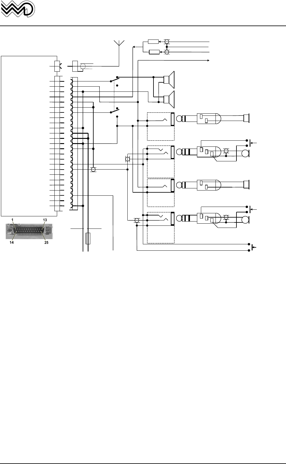
FSG 90F System
3. Installation
November 2000 Page 27
W. Dittel GmbH
13.75 V Lighting HI
from Dimmer or
lighting switch
A/C Speaker out
Headphone (HI) out
Headphone (LO) out
AF External
Dynamic Microphone (HI)
Dynamic Microphone (LO)
Intercom
RTS
RxD
Display Lighting LO
+13.75 V A/C Power
+ 13.75 V A/C Power
Power Ground
Microphone GND
RX Signal
AF Sum
PTT Switch
Amp/Carbon Microphone
AF Modem out
CTS
Data Ground
TxD
+13.75 V Lighting HI
Switched 13.3 Vdc OUT
Power Ground
FSG 90F(X)
Antenna cable
RG 58 C/U
A/C antenna
1
2
3
4
5
6
7
8
9
10
11
12
13
14
15
16
17
18
19
20
21
22
23
24
25
Antenna
+-
#18 AWG
1 mm² red
#18 AWG
1 mm²
blue
INTERCOM-
Switch ¬OFF
ô
ON
A/C POWER
13.75 V
*Built-in stick
PTT switch
Pilot
Amplified/Carbon
microphone *with
PTT switch
1
2
A/N E08639
Headphone
Jack
JJ-034
1
2
1
2
3
Microphone
Jack
JJ-033
A/N E08640
12
3
Headphone Plug PJ-055
A/N E08941
Microphone Plug
PJ-068, A/N E08942
Pilot
Headphone
Copilot
Amplified/Carbon
microphone *with
PTT switch
1
2
A/N E08639
Headphone
Jack
JJ-034
1
2
1
2
3
Microphone
Jack
JJ-033
A/N E08640
12
3
Headphone Plug PJ-055
A/N E08941
Microphone Plug
PJ-068, A/N E08942
Copilot
Headphone
1 or 2 A/C speaker
4 Ω to ∞
¬¬
AF External input
e.g. COM 2, NAV, MKR
Audio OUT to Audio Panel
(as required)
470 R
470 R
¬¬
#20 AWG
#20 AWG
DA-25S
NOTES:
DO NOT wire other pins than noted!
Unless otherwise noted all wires #22 AWG (0.3 -0.4 mm²).
Unless otherwise noted all Power Grounds are airframe grounds.
Intercom operation requires a microphone which provides audio OUT with the PTT key
de-energized (not keyed).
Intercom operation requires a selector switch, double pole, double throw.
Terminate audio shields at one end only.
Power bus circuit breakers are to be mounted in the A/C breaker panel or instrument
panel such that they will be accessible in flight and safe from physical damage.
* PTT Key/s either at hand-held microphone/s or permanently installed on the yoke.
¬Wiring without Intercom: connect A/C speaker direct to pins 11 and 15.
¬¬ If more than one AF source, isolation resistors 470 Ohm shall be installed.
¬¬¬ Fuse 3.15 Amp, quick acting, or circuit breaker 3 Amp.
FIG. 3-7: FSG 90F System
HOOK-UP DIAGRAM
2 AMPLIFIED/CARBON MICROPHONES
AND INTERCOM

FSG 90F System
3. Installation
Page 28 November 2000
W. Dittel GmbH
3.5.2 Microphone Connection
Independent of each other, almost any non-amplified dynamic microphone, or amplified
Electret or amplified dynamic or carbon standard microphones can be connected to the
FSG 90F System, without internal jumper setting or soldering.
A amplified/carbon microphone is connected to pin 18, a dynamic microphone is
connected to pin 5 of the 25-pole SUB-D receptacle. Avoid any ground loop in
microphone wiring (dynamic non-amplified mike shield shall not be connected to any
other aircraft wiring, except directly at the assigned pin in the accessory connector).
Up to two IDENTICAL microphones for pilot and copilot can be operated in parallel
simultaneously. Even two low impedance (4 Ohm) dynamic microphones may be
connected in parallel as well. However, for microphones with less than 30 Ohms, it may
be necessary to use a suitable microphone transformer.
The associated microphone ground (shield) for dynamic microphones must be
consequently routed galvanically isolated, in order to avoid any ground loop.
This means, dynamic mike ground/shield must be separated from any other grounds for
DC input or DC output, AF input and AF output like speaker, phone, PTT and external
Audio).
In this context, due to the extremely wide mike input level adjustment range, it is
mandatory to understand that correctly matched FSG 90F(X) mike input sensitivity (SET-
UP) will be good ONCE FOREVER for this configuration and to ensure stable operation
without audio feedback.
IMPORTANT!
The 3-pole mike connector type PJ-069 MUST NEVER be used when using
non-amplified dynamic microphones, because ground for mike and PTT is
identical. This would create a ground loop and cause unstable / distorted
modulation. This PJ-068 is allowed only for amplified/carbon mikes.
However, the PJ-068/PJ-55 connector system must be regularly cleaned,
contacts shall have sufficient spring-loaded force. This is especially
mandatory under vibration operating conditions.
3.5.3 Intercom (IC)
Intercom is suitable for twin seater aircraft with noisy cockpit. Intercom as well as radio
operation should employ suitable aircraft headsets which must be matched properly to
the transceiver (refer to SET-UP).
Hand-held microphones may be useful for intercom, if audio is not switched/keyed ON /
OFF by the PTT function. Keying the mike audio may cause awful cracks, depending on
mike technology.
To control the intercom capability, aircraft radio wiring must have a two-pole toggle
switch (refer to figure 3-6 or 3-7). The intercom switch disconnects the loudspeaker
during IC operation in the IC ON position. Simultaneously, pin 7 of the 25-pole connector
is set to ground to select IC ON by continuously activating the microphone amplifier
input signal.
With the IC switch in "ON" position it is possible anytime to perform normal transmitting
(with the normal PTT key), it also allows continuous intercommunication during receive
between pilot and copilot/crew (no PTT action is required for any IC operation).
During receive, while IC is ON, both the IC loudness and external audio volume are
temporarily reduced to improve receive intelligibility.
Receiving volume is set on the FSG 90F(X) front panel (VOL), while intercom volume
can be optimized with a SET-UP adjustment.

FSG 90F System
3. Installation
November 2000 Page 29
W. Dittel GmbH
3.5.4 Loudspeaker / Headset interconnection
Two separate audio outputs are provided. The speaker output pin 1 can continuously
supply up to two speakers each with 4 Ohms (load > 2 Ohms), while the headphone
audio output pins 2 and 3 can accommodate up to 2 or more headphones each with
some 600 Ohms, or all may be connected also simultaneously.
When no speaker is installed, this Pin 1 may remain not connected, no spare load is
required.
CAUTION!
• The magnet compass will be deflected by the speaker's magnetic
field. Therefore, when using the Walter Dittel compact speaker box
F10061, a minimum distance of 1.3 m/4.3 ft. between compass and
speaker is required.
3.5.5 AF External Operation
The AF external input pin 4 may be connected to any external (selectable) audio output
of any other audio source. 1 Volt rms is necessary to obtain maximum audio volume.
Higher AF input may cause audio distortion. External AF will be audible only in Receive
mode and in Standby mode, and may be heard in both speaker and headphones.
During transmit, the external AF input is disabled.
Continuous interconnection of an external audio source(s) will be suitable especially in
aircraft using just one COM and one NAV. Then the NAV headphone output may be
connected directly to the FSG 90F(X) external AF input.
This allows in addition to the receiving and intercom function also the simultaneous
listening of COM and NAV audio either by headphones or speaker.
Interconnection of more than one external audio source requires additional external
decoupling/isolation resistors (470 Ohms, refer to figure 3-7).
The individual audio volume is set directly at the particular external equipment.
IMPORTANT!
• If external audio sources should be audible via A/C speaker, the external
AF input must be enabled in the SET-UP. The 30 mA current saving in
standby mode is then disabled.
To achieve in External Audio operation the maximum FSG 90F(X) AF output power, a
minimum AF input level of 1 Volt rms is required (approx. 10 kOhm input impedance).
Interconnecting AF wiring must use shielded wires in order to avoid interference from
strong electrical fields. A possible magnetic interference coupling shall be especially
regarded (distance from high current carrying wiring).
3.5.6 Lighting the Frequency Display
IMPORTANT!
• Lighting operates separately and will not be controlled by the radio.
• In order to save current while supplied from battery an external suitable
illumination switch is suggested.
The FSG 90F(X) includes a display which can be back-lit. Pin 23 may be connected
either directly to 14 Volt or to the switched 13.3 Vdc output Pin 24 (perhaps via a
suitable dimmer). For dimmer operation from 28 Vdc supply, insert a 680 Ohm resistor /
0.5 W, connected in series.
CAUTION!
• This way of matching to 28 Volt is only suitable for the lighting!
• The FSG 90F(X) always requires a 12 to 14 Volts DC supply.

FSG 90F System
3. Installation
Page 30 November 2000
W. Dittel GmbH
3.5.7 Connection to a 28 Vdc airborne system
Interconnection of the FSG 90F(X) transceivers to a 28 Vdc supply requires a capable
voltage converter. Interconnection wiring shall be according to instructions of the DC
converter's manufacturer. For lighting interconnection refer to Section 3.5.6.
3.6 Post-installation Check
3.6.1 Testing on the Ground with Engine Off
Verification after installation completion
After installing the unit, check all aircraft control movements to be sure no electrical
cable interfere with their operation. All aircraft and radio functions shall be tested after
installation completion to identify, whether malfunctions caused by mechanical and/or
electrical installation work occurs.
This must be performed by an Authorized Aircraft Electronics Inspector.
Testing of antenna matching between the FSG 90F(X) antenna socket (BNC) and the
BNC antenna cable connector is required, using a suitable 50 Ohm VHF Reflectometer
(VSWR meter), or a directional Wattmeter.
The VSWR must be less than 3 : 1 over the full frequency range, tested at least in 1
MHz steps (reflected power shall be less than 25% of the forward RF power output). If
this limit is exceeded, this indicates a mismatched antenna and may be caused by
wrong antenna radiator or counterweight length/dimensions, poor contacts, or damaged
or wrong (no 50 Ohm) coaxial cable.
In order to optimize radio range, it is suggested to care for an VSWR of less than 2 : 1
(reflected power shall be less than 11% of the forward RF power output).
After completion of the antenna matching measurements, perform the following test
sequence:
• All audio level settings (microphone(s), phone(s), speaker, intercom through the
SET-UP (refer to Section 5).
• Check radio with a known base station, as well as with distant airborne station(s).
IMPORTANT!
• If the antenna is belly mounted, perform antenna matching
measurements if possible in flight, or at least while the fuselage is lifted
upwards, using wood/non metallic supporting material. This avoids
antenna mismatch caused from ground proximity.
• Using known, but distant located fixed stations (VOLMET, ATIS) will also
help in determining the radio range, especially in comparison with known,
other radio range results of another aircraft at the same position on the
ground at a known airfield location, or outside of the hangar or workshop.
3.6.2 Ground checks with engine running
It must be ensured that the aircraft's electrical DC system voltage at the FSG 90F(X)
input terminals is within the tolerances permitted at 14 Vdc (or 28 V with DC converter).
Battery only supplied systems operate from 10 to 16.5 Vdc. Such testing requires
normal RPM rated at cruising speed.
This testing evaluates both the audio / noise influence, and RF radio range, at least from
10 to 30 km distance to the ground radio station. With cruising RPM, cabin noise
background content shall almost not exist. Instead, loud and clear communications shall
be achieved!
The microphone shall be in both transmit and intercom mode placed right at the lips in
order to obtain maximum voice level at lowest cabin noise content. Speak loud and