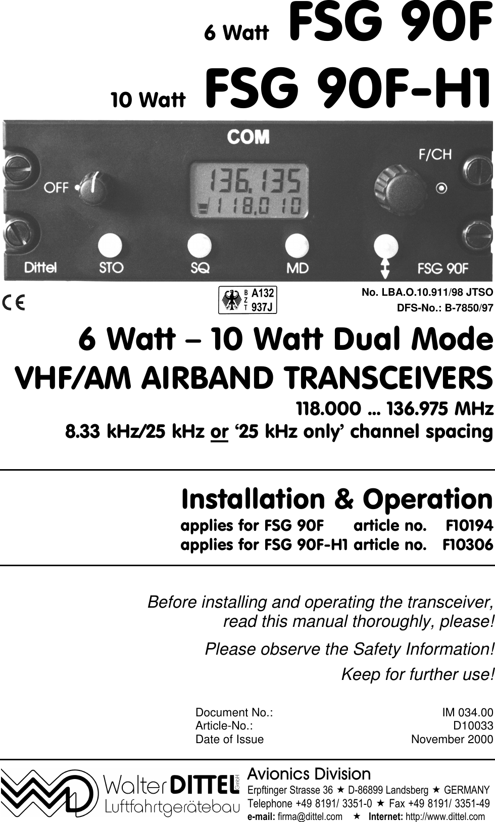
f u n k e AVIONICS FSG90 VHF/AM aviation analogue voice COMM transceiver User Manual FSG90F Installation Operation 11 2000

f.u.n.k.e. AVIONICS GmbH VHF/AM aviation analogue voice COMM transceiver FSG90F Installation Operation 11 2000

FSG 90F ops manual part one
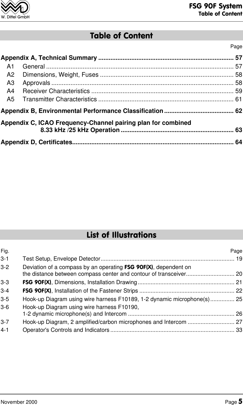
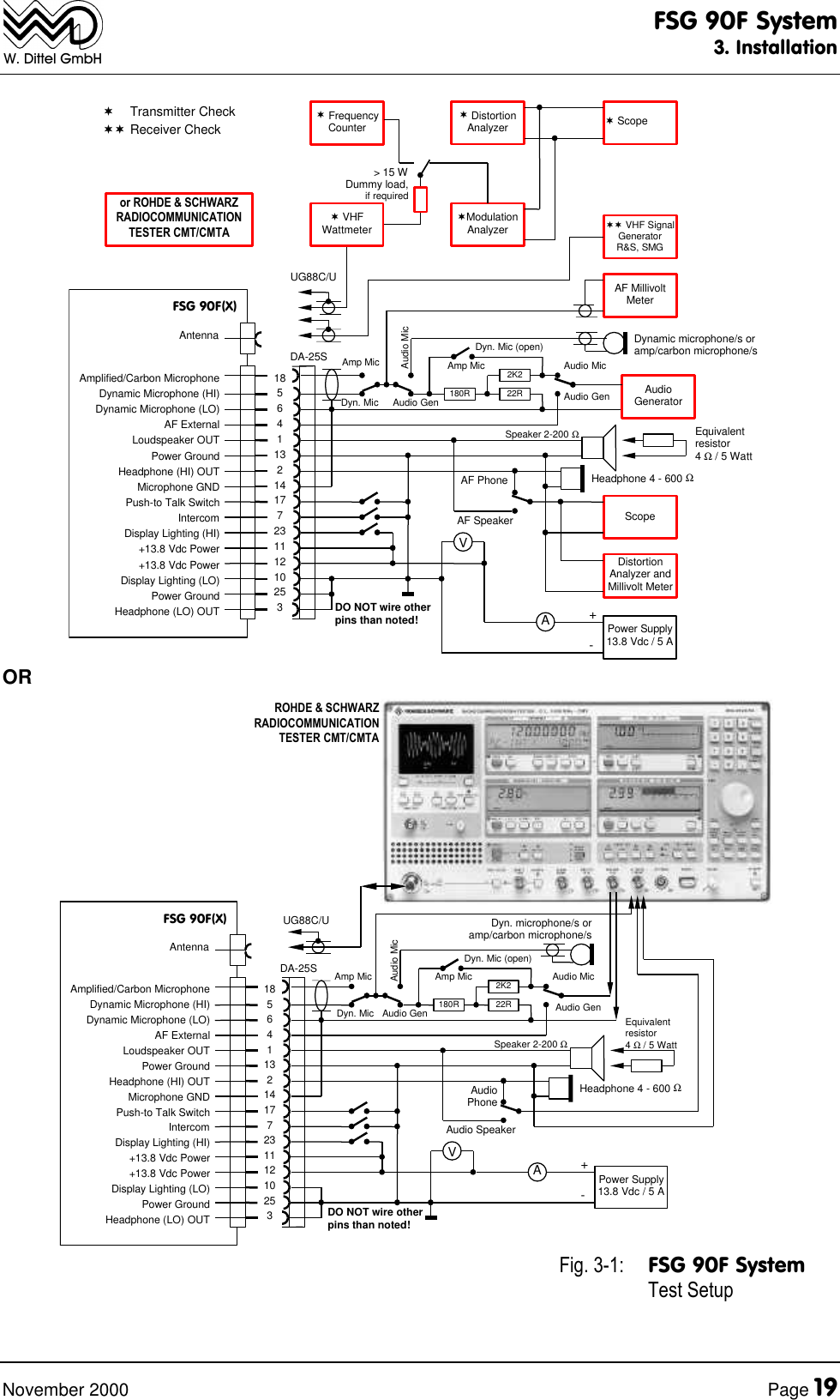
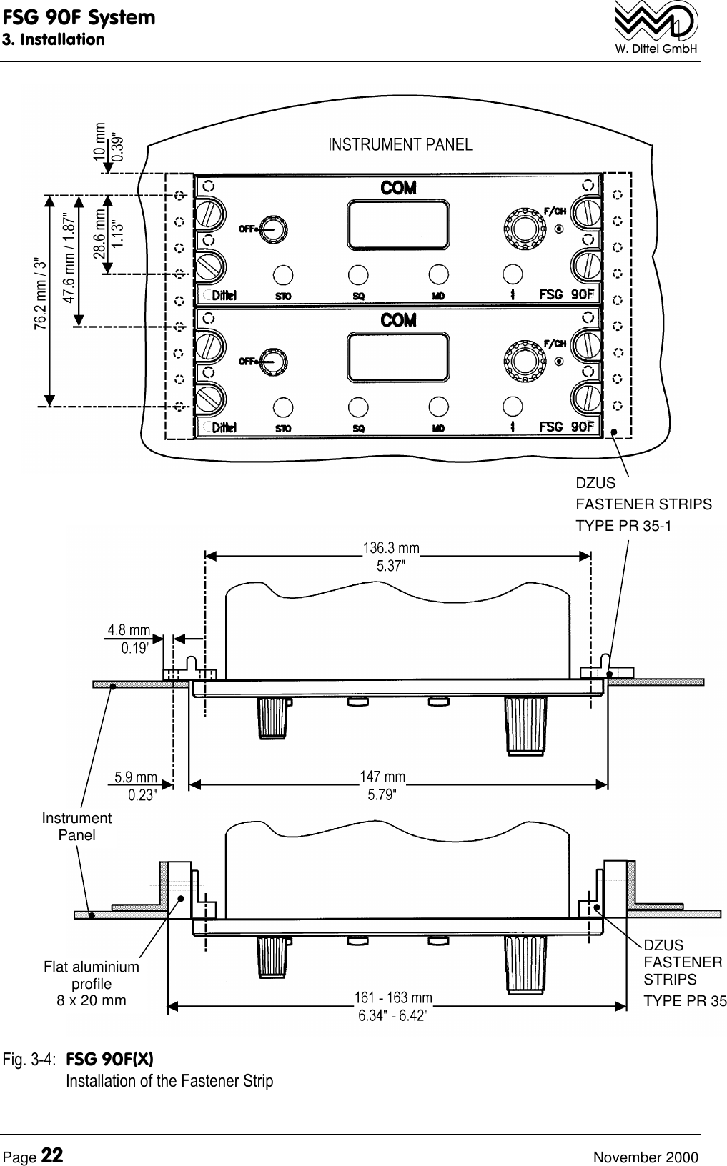
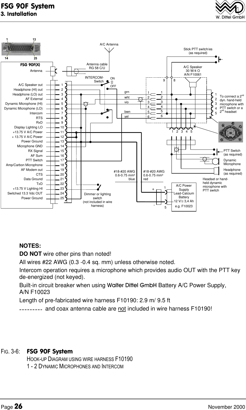
6 Watt FSG 90F10 Watt FSG 90F-H1No. LBA.O.10.911/98 JTSODFS-No.: B-7850/976 Watt – 10 Watt Dual ModeVHF/AM AIRBAND TRANSCEIVERS118.000 ... 136.975 MHz8.33 kHz/25 kHz or ‘25 kHz only’ channel spacingInstallation & Operationapplies for FSG 90F article no. F10194applies for FSG 90F-H1 article no. F10306Before installing and operating the transceiver,read this manual thoroughly, please!Please observe the Safety Information!Keep for further use!Document No.: IM 034.00Article-No.: D10033Date of Issue November 2000Avionics DivisionErpftinger Strasse 36 « D-86899 Landsberg « GERMANYTelephone +49 8191/ 3351-0 « Fax +49 8191/ 3351-49e-mail: firma@dittel.com    «   Internet: http://www.dittel.com
FSG 90F SystemAirband TransceiverPage 2November 2000W. Dittel GmbHWarranty - Copyright - ServiceWarrantyThe details and data in this operator's manual correspond to the respectivestate of technology on the day of printing. We reserve our right to changewithout prior notice due to new technological design or corresponding newproduction technology.Walter Dittel GmbH takes no guarantee for these documents with respect toapplication and interpretation.Walter  Dittel GmbH ("Warrantor") warrants to the purchaser of new radioequipment of the warrantor's manufacture that such equipment shall be freefrom defects in material and workmanship for a period of 24 month from thedate of delivery. Equipment and accessory items not manufactured by theWarrantor carry the standard warranty (12 month) of the manufacturerthereof.This warranty does not cover equipment which has been1. damaged or not maintained as reasonable and necessary,2. modified in any way,3. improperly installed,4. repaired by someone other than the warrantor or an authorizedwarranty avionics shop, or5. used in a manner or purpose for which the equipment was notintended.This warranty shall not extend to incidental or consequential damages arisingfrom operation of the equipment or from any claimed breach of this warranty.Copyright  1998 Walter Dittel GmbHAll rights reserved. This document contains proprietary information and suchinformation may not be disclosed to others for any purpose nor used formanufacturing purposes without prior written permission of the manufacturerWalter Dittel GmbH, Luftfahrtgeraetebau, D-86899 Landsberg am Lech,Germany.In this document no mention is made of patents, trademark rights, or otherproprietary rights which may attach to certain words or entries. The absenceof such mention, however, in no way implies that the words or entries inquestion are exempt from such rights.ServiceThe information in this Operator's Manual does not profess to include all thedetails of design, production, or variation of the equipment, or to cover all thepossible contingencies which may arise during operation or maintenance.Should any unusual problem arise or further information be desired, pleasecontact the Walter Dittel GmbH Service Department, Erpftinger Strasse 36,D-86899 Landsberg am Lech, Germany.Subject to technical changes Printed in Germany 14.09.01
FSG 90F SystemTable of ContentNovember 2000 Page 3W. Dittel GmbHTable of ContentPageWarranty - Copyright - Service..................................................................................... 2Table of Content............................................................................................................ 3List of Illustrations........................................................................................................ 5Abbreviations................................................................................................................ 6Section 1, Safety Information....................................................................................... 71.1 Used Symbols.................................................................................................... 8Section 2, General Description.................................................................................... 92.1 Introduction ........................................................................................................ 92.2 Models of the FSG 90F System .......................................................................... 92.3 Application.......................................................................................................... 92.4 Brief Description............................................................................................... 102.5 System and Type Approval Information ........................................................... 122.6 Operating License............................................................................................ 132.7 Equipment supplied.......................................................................................... 132.8 Optional Accessories ....................................................................................... 142.9 Accessories required, but not supplied ............................................................ 152.10 Microphone hints.............................................................................................. 15Section 3, Installation................................................................................................. 173.1 General ............................................................................................................ 173.2 Unpacking and Inspecting Equipment.............................................................. 173.3 Pre-installation Test ......................................................................................... 173.3.1 Particular Remarks to FSG 90F(X) transmitter modulation .................................... 183.4 Mechanical Installation..................................................................................... 203.4.1 Transceiver installation ......................................................................................... 203.4.2 Compass deviation ............................................................................................... 203.4.3 Antenna installation............................................................................................... 233.5 Airborne wiring ................................................................................................. 243.5.1 General recommendations.................................................................................... 243.5.2 Microphone Connection ........................................................................................ 283.5.3 Intercom (IC)......................................................................................................... 283.5.4 Loudspeaker / Headset interconnection................................................................ 293.5.5 AF External Operation .......................................................................................... 293.5.6 Lighting the Frequency Display............................................................................. 293.5.7 Connection to a 28 Vdc airborne system .............................................................. 303.6 Post-installation Check..................................................................................... 303.6.1 Testing on the Ground with Engine Off................................................................. 303.6.2 Ground checks with engine running...................................................................... 30
FSG 90F SystemTable of ContentPage 4November 2000W. Dittel GmbHTable of ContentPageSection 4, Functional Description ............................................................................. 334.1 Introduction....................................................................................................... 334.2 Operator's Controls .......................................................................................... 334.3 Frequency Display, 5-digit or 6-digit Liquid Crystal Display (LCD). .................. 364.4 Connectors at rear side.................................................................................... 37Section 5, Set-up Procedure ...................................................................................... 395.1 Calling SET-UP without password.................................................................... 405.2 Calling SET-UP with password......................................................................... 405.3 Interrupt the SET-UP procedure....................................................................... 415.4 SET-UP procedure........................................................................................... 415.4.1 Adjusting the automatic squelch threshold ............................................................415.4.2 Adjusting the microphone sensitivity (Dynamic or amplified/carbon microphones) 415.4.3 Adjusting the Intercom volume ..............................................................................425.4.4 Adjusting the Sidetone volume ..............................................................................435.4.5 Adjusting the headset volume ...............................................................................435.4.6 Selecting '25 kHz only' or combined 8.33/25 kHz channel spacing........................445.4.7 Deleting occupied channel memories....................................................................445.4.8 Selecting AF EXTERNAL (ON/OFF) .....................................................................455.4.9 Selecting 'CHANNEL MODE ONLY' or 'NO RESTRICTION' .................................455.4.10 Selecting 'Transmitter Blocking' during receive (ON/OFF).....................................455.4.11 Service (ON/OFF) .................................................................................................465.4.12 Optional module (ON/OFF) ...................................................................................465.4.13 Entering a password..............................................................................................465.4.14 Reset.....................................................................................................................47Section 6, Operating Instruction................................................................................ 496.1 Introduction....................................................................................................... 496.2 Turning ON - Selecting Frequency/Channel Name - Volume........................... 496.3 Receive (Listen) Operation............................................................................... 506.4 Transmit (Talk) Operation ................................................................................ 516.5 Storing a new Frequency/Channel Name......................................................... 526.6 Recall of stored Frequency/Channel Name...................................................... 526.7 Squelch (SQ) Operation................................................................................... 526.8 Intercom ........................................................................................................... 536.9 AF External....................................................................................................... 536.10 Lighting............................................................................................................. 536.11 Turning OFF..................................................................................................... 536.12 Checking the A/C onboard supply.................................................................... 546.13 Operating times with radio supplied from 12 V battery only ............................. 556.14 Emergency Operation ...................................................................................... 55
FSG 90F SystemTable of ContentNovember 2000 Page 5W. Dittel GmbHTable of ContentPageAppendix A, Technical Summary .............................................................................. 57A1 General ............................................................................................................ 57A2 Dimensions, Weight, Fuses ............................................................................. 58A3 Approvals ......................................................................................................... 58A4 Receiver Characteristics .................................................................................. 59A5 Transmitter Characteristics .............................................................................. 61Appendix B, Environmental Performance Classification........................................ 62Appendix C, ICAO Frequency-Channel pairing plan for combined                       8.33 kHz /25 kHz Operation ................................................................. 63Appendix D, Certificates............................................................................................. 64List of IllustrationsFig. Page3-1 Test Setup, Envelope Detector................................................................................... 193-2 Deviation of a compass by an operating FSG 90F(X), dependent onthe distance between compass center and contour of transceiver.............................. 203-3 FSG 90F(X), Dimensions, Installation Drawing............................................................ 213-4 FSG 90F(X), Installation of the Fastener Strips ........................................................... 223-5 Hook-up Diagram using wire harness F10189, 1-2 dynamic microphone(s)............... 253-6 Hook-up Diagram using wire harness F10190,1-2 dynamic microphone(s) and Intercom .................................................................. 263-7 Hook-up Diagram, 2 amplified/carbon microphones and Intercom ............................. 274-1 Operator's Controls and Indicators............................................................................. 33
FSG 90F SystemAbbreviationsPage 6November 2000W. Dittel GmbHAbbreviationsA/C AircraftA/N Article Number (DITTEL)AGC Automatic Gain ControlAh Ampere hourAM Amplitude ModulationANT AntennaAss'y AssemblyAWG American Wire Gaugeccw Counterclockwise (turn left ?)CH ChannelCTS Ready-to-Transmitcw Clockwise (turn right ?)dB Decibeldia. DiameterEMF Electromotive Force (voltage ofan open circuit)F/CH Frequency/ChannelFL Flight LevelgAcceleration due to gravityGND GroundHI High PowerHz HertzICAO International Civil Aviation OrganizationIF Intermediate FrequencykHz KilohertzLCD Liquid Crystal DisplayLED Light Emitting DiodeLO Low PowerLOS Line-Of-SightmModulationmA MilliamperesMD ModeMHz MegahertzMIC MicrophonemW MilliwattNM Nautical milesnW Nanowatt (10-9)PEP Peak Envelope PowerPLL Phase-Locked Loopppm parts per millionPTT Push-To-TalkpW Picowatt (10-12)PWR PowerRF Radio Frequencyrms Effective value (root meansquare)RTS Invitation to sendRX ReceiveRxD Receive dataS+N/N Signal-to-Noise RatioSINAD Ratio:  Signal noise distortionnoise distortion+ ++SPKR LoudspeakerSQ SquelchSTBY StandbySTO StoreSWR Standing-Wave RatioTOT Time out timerTX TransmitTxD Transmit dataVCO Voltage-Controlled OscillatorVdc Volts, direct currentVHF Very-High FrequencyVOL VolumeVSWR Voltage Standing-Wave RatioWWattOOhm°C Degrees Centigrade°F Degrees Fahrenheit
FSG 90F System1. Safety InformationNovember 2000 Page 7W. Dittel GmbHSection 1 Safety InformationEvery radio, when transmitting, radiates energy into the atmosphere that may, undercertain conditions, cause the generation of sparks. All users of our radios should beaware of the following warning:Do not operate this radio in an explosive atmosphere (petroleum fuels,solvents, dust, etc.)!During normal use, the radio will subject you to radio frequency energy substantiallybelow the level where any kind of harm is reported.TO ENSURE PERSONAL SAFETY, please observe the following simple rules:• DO NOT transmit when the antenna is very close to, or touching, exposed parts of thebody, especially the face and eyes.• DO NOT transmit on a busy channel.• DO NOT press the transmit (PTT) key when not actually desiring to transmit.• DO NOT transmit in closed aircraft or vehicles with the antenna (or part of it) inside thecabin. This may cause malfunction of the avionics or trigger the airbag! Always operatethe radio FSG 90F(X) with a suitable outside / external antenna! Assure appropriatelightning protection where elevated outdoor antennas are used.• DO NOT operate the radio whilst driving. It should also be noticed that the use of ahand held microphone while driving could constitute an offence under the Road TrafficRegulations in certain countries.• DO NOT allow children to play with any radio equipment containing a transmitter.• DO NOT call radio’s SET-UP in flight or whilst driving a vehicle. Transmit and receiveare partially disabled!• After each SET-UP check all settings of the radio and cockpit instruments for correctfunction before the next flight or application!• Always switch OFF the radio first when installing the unit into vehicles or aircraft whenremoving from it!• Always switch OFF the radio first when starting an engine or vehicle!• When operating the FSG 90F(X) on a 24 Vdc source a suitable Voltage Converter24 Vdc/12 Vdc of at least 4 Amps must be used!• The FSG 90F(X) may be used exclusively for communication on the airbandfrequencies.• Unauthorized modifications and changes of the system are forbidden.• When replacing defective parts use only original spare parts or standard partsrecommended by the manufacturer!• In aircraft or vehicles a suitable noise canceling microphone or headset for aircraftradios shall be used.• A backup microphone should always be carried during any flight. Even newmicrophones can fail.• Volume is very important. Increasing speaking levels while the lips are facing themicrophone, but not straining or pushing to yelling levels will increase clarity.
FSG 90F System1. Safety InformationPage 8November 2000W. Dittel GmbH• Prior to any flight verify proper FSG 90F(X) functions by means of a shortcommunications test. It has to be taken into account that with a faulty antenna orcable this COM test may absolutely turn out positive at the airfield or in short distanceto the ground station. But at distances of 2 to 6 miles a faulty antenna and/or cablewill cause communication breakdown!• Push-to-Talk keys may stick occasionally. Therefore, observe while transmitting thetransmit (TX) symbol at the FSG 90F(X) display. This TX symbol must disappearwhen releasing the PTT key. After 2 minutes continuous TX the built-in transmit timeout timer disables the transmitter in order to avoid continuous channel blocking.Then, the whole display warns by continuous flashing. Refer to appropriate hints inthis manual.• Replace blown fuse only against correct type with specified nominal value.Investigate the cause.1.1 Used SymbolsIn this manual the following symbols are used:DANGER!describes an immediate threatening danger! Failing to observe the notemay cause death or heavy injuries!CAUTION!describes a special note for operation. Failing to observe the note maycause damage of the transceiver and/or stored data may be deleted (SET-UP or user programmed memory)!IMPORTANT!describes explanations and other useful hints. Failing to observe the notemay cause degraded performance and/or unsatisfying operation!
FSG 90F System2. General DescriptionNovember 2000 Page 9W. Dittel GmbHSection 2 General Description2.1 IntroductionThis installation and operating manual IM 034.00 contains instructions and descriptionsfor application, installation, presetting operation and testing, as well as interconnectingdiagrams of the multi-use FSG 90F / FSG 90F-H1 VHF/AM Transceiver System of WalterDittel GmbH, Luftfahrtgeraetebau, D-86899 Landsberg, Germany.The maintenance manual MRM 034.00 contains detailed circuit description, repairinstructions, alignment procedures, testing instructions, and an illustrated parts list.2.2 Models of the FSG 90F SystemThis manual refers to 2 out of 8 models available up to now.F10194, VHF/AM Dual Mode Airband Transceiver FSG 90FFrequency range: 118.000 to 136.975 MHz, channel spacing 8.33 kHz/25 kHz, results in2,278 channels, or 118.000 to 136.975 MHz, channel spacing 25 kHz, results in 760channels. 99 channel memories for combined 8.33/25 kHz mode, additional 99 memorychannels for '25 kHz only' mode, 6 Watt RF output power, 10 - 16.5 Vdc supply. Theradio fits a standard ARINC NORM rectangular opening.IDENT.: MODEL 90F-25/8.33 (ED-23B CLASS C / CLASS E RECEIVER, CLASS 4 / CLASS 6TRANSMITTER).F10306, VHF/AM Dual Mode Mode Airband Transceiver FSG 90F-H1Frequency range: 118.000 to 136.975 MHz, channel spacing 8.33 kHz/25 kHz, results in2,278 channels, or 118.000 to 136.975 MHz, channel spacing 25 kHz, results in 760channels. 99 channel memories for combined 8.33/25 kHz mode, additional 99 memorychannels for '25 kHz only' mode, 10 Watt RF output power, 10 - 16.5 Vdc supply. Theradio fits a standard ARINC NORM rectangular opening.IDENT.: MODEL 90F-H1-25/8.33 (ED-23B CLASS C / CLASS E RECEIVER, CLASS 4 / CLASS 6TRANSMITTER).2.3 ApplicationThe equipment is well suited for operation in powered aircraft and helicopter withreciprocating turboprop and turbojet engine.Ultra low power consumption in conjunction with extremely wide DC supply voltagerange, small dimensions and wide scope of accessories allow universal FSG 90F(X)airborne applications in any powered aircraft, motor glider and Ultralight, and in gliderand balloon, for primary or (also battery supplied) backup operation.
FSG 90F System2. General DescriptionPage 10 November 2000W. Dittel GmbH2.4 Brief DescriptionBoth radios out of the FSG 90F System are miniaturized, lightweight, panel-mounted1.8" high flat-pack VHF/AM transceivers operating in the airband frequency range118.000 MHz ... 136.975 MHz, thus providing either 2,278 channels with 8.33 kHz/25 kHz channel spacing, or 760 channels only with 25 kHz channel spacing, covering astandard communications distance of 100 NM (nautical miles) at FL 70.Case dimensions of all models will fit into a standard ARINC NORM rectangular openingof the instrument panel or console, fixing is done by 4 DZUS fasteners. Depth includingwiring is 215 mm.All control and display elements are located on the front panel. Connections to theelectrical environment are made through a 25-pole SUB-D connector and a BNC femaleconnector at the rear panel of the units.The ICAO channel name (8.33 kHz/25 kHz spacing) and / or operating frequency(25 kHz spacing), supply indicator, transmit indicator, channel memory number andSET-UP information are all indicated at a two-line Liquid Crystal Display (LCD, can beback-lit).Three display modes are user selectable:• Use/STBY Mode: Active channel name or frequency, selectable standby channelname / frequency• Channel Mode: Active channel name or frequency, associated preset channelmemory number (1 … 99)• Direct Tune Mode: Active channel name or frequency only.With the Dual Mode models FSG 90F and FSG 90F-H1, up to 99 channel memories in8.33 kHz / 25 kHz CH spacing (6-digit display), and another set of up to 99 channels inthe '25 kHz only' CH spacing (5-digit display) can be preset. After change to the otheroperating mode (from 8.33/25 kHz to 25 kHz only, or from 25 kHz only to 8.33/25 kHz),each stored set of up to 99 channel memories remains available.Preset channel memories remain available also after manual or automatic power-off.The non-volatile channel memories of the FSG 90F(X) can easily reprogrammed alsoduring flight or ground operation.Programming can be done in the actual (8.33/25 kHz or 25 kHz only) mode.Deleting channel memories is only possible during SET-UP.For ground applications, limitation to use preset channel(s) only can be determined in(password protected) SET-UP.Channel name / frequency, or preset channel memories are selected with the dualfunction F/CH switch.Both Transmit and Receive use the same digital frequency synthesizer and onetemperature calibrated reference crystal (accuracy 1 ppm).The dual Superhet receiver offers very high immunity against in-band and out-of-bandinterference and intermodulation (Annex 10 FM immunity).The automatic AM/FM Squelch (threshold adjustable in 4 levels, SET-UP) and thenormally active transmitter blocking during Receive are disabled by pushing the SQbutton, and enabled when the SQ button is pushed again.An audio low pass filter for areas using Climax operation in 25 kHz spacing isincorporated.Separate Audio amplifiers power the speaker (4 Watts / 4 Ohms or 8 Watts / 2 Ohms),and the headphones (100 mW / 600 Ohms).The solid state transmitter is wideband tuned from 118 to 137 MHz and delivers at leastan RF carrier power of 6 Watts or 10 Watts for the FSG 90F-H1 model.
FSG 90F System2. General DescriptionNovember 2000 Page 11W. Dittel GmbHTransmit frequency / channel name is tuned simultaneously with Receive frequency /channel name (Simplex operation).A keyed transmitter is indicated by a transmit symbol at the LC display.Two independent microphone inputs (separate pins) allow universal accessoryoperation:• For powered aircraft use Standard Carbon, amplified Dynamic or Electretmicrophones,• For gliders, portable, vehicle mobile, and fixed base operation use non-amplifiedDynamic microphones.The microphone inputs may also be continuously activated. This allows during Receivecontinuous intercommunication (no additional accessories needed) between pilot andcrew (intercom wiring harness), using headsets.A separate AF input allows interconnection of external audio source(s) especially inaircraft using other COM, VOR/LOC, DME, MKR and / or electric variometers. Thisallows signal monitoring during Receive by speaker and / or headphone.30 mA current consumption saving can be achieved in standby mode (Squelch ON),when the FSG 90F(X) is used in installations, where no external audio is required forspeaker output. Listening through headphone remains however possible. This externalAF OFF function may be selected in SET-UP. This reduces the standby currentconsumption to only 80 mA and will extend battery supplied operating time significantly.The transceiver can be supplied either directly from a 12 to 14 Vdc A/C bus, or througha suitable DC regulator from 28 Vdc-buses.In aircraft without onboard electric power generation system (UL, Glider etc.), operationfrom a rechargeable 12 Vdc battery (min. 6 Ah) is suitable.The DC supply voltage is monitored continuously while the radio is ON. When supplydrops below 11 Vdc, the Supply Indicator at the LC display starts blinking as a lowsupply warning.Below 8.5 to 9.5 Vdc, the FSG 90F(X) turns OFF itself automatically, and will resumeoperation with supply above 9.5 to 10 Vdc. The last used settings remain active.A voice processor is incorporated to achieve identical acoustic voice quality duringTransmit and Receive, as well as Audio Leveling in Receive, and in addition preventsovermodulation in both Single and Dual channel spacing Mode. Usual testing employssinusoidal tone signals only; this feature especially considers the specific characteristicof the voice. It ensures also VERY HIGH AVERAGE DEPTH OF MODULATION ofsome 80% AM, causing transmission signals sounding normal and very strong.The radios are equipped with a time out timer. This avoids blocked channel after 2minutes continuous TX (stuck button does no longer block a channel continuously) andis indicated by a continuously blinking display. Should the malfunction continue theFSG 90F(X) is ready for another 2 minutes transmission period when turning OFF andON again (e.g. for emergency transmissions).The transmitter blocking feature avoids transmission on a busy channel. Transmitterblocking is usually active, but may be disabled permanently in SET-UP or manually bypushing the SQ button.
FSG 90F System2. General DescriptionPage 12 November 2000W. Dittel GmbH2.5 System and Type Approval InformationThe Dual VHF/AM Airband Transceivers FSG 90F(X) comply for both, the combined8.33 kHz/25 kHz as well as "25 kHz only" channel spacing with all applicable Nationaland International Type Approval requirements, for any airborne and ground operations.2.5.1 JTSO Authorization LBA.O.10.911/98 JTSO (LBA Luftfahrt-Bundesamt) based on*EUROCAE ED-23B Airborne requirement is met besides 8.33 kHz requirements alsofor the 25 kHz ONLY channel spacing.This also includes Immunity according to ICAO ANNEX 10 against FM BroadcastInterference.This also includes fulfillment of specific audio filtering required in areas with CLIMAXoperation in 25 kHz channel spacing.* Associated EUROCAE ED-14C / RTCA DO-160C Environmental requirements.* Associated EUROCAE ED-12B Software requirements based on ED-23B.2.5.2 Reg TP No. A132937J, stringent German Type Approval requirements Reg TP321 ZV 034 (airborne) and Reg TP 321 ZV 039 (ground).2.5.3 DFS (Deutsche Flugsicherung) No. B-7850/97 (ground) German Type Approvalrequirements.2.5.4  BZT No. B132705J, CE Conformity,* Associated with DIN/ISO 7637-1 DC supply in 12 V vehicle.IMPORTANT!• For the first time after one year, then every 2nd year, groundapplications using 8.33 kHz channel spacing require checking ofthe high precision reference frequency (tolerance less than± 1.5 ppm) and recalibration, if necessary!• Every 4th year, airborne applications using 8.33 kHz channelspacing require checking of the high precision reference frequency(tolerance less than ± 5 ppm) and recalibration, if necessary!• All applications in the 25 kHz channel spacing require norecalibration (frequency accuracy tolerance less than ± 20 ppm).• All tolerances include the full operating temperature range of-20°C ... +55°C / -4°F ... +131°F.• Checking and recalibration must be performed by the equipmentmanufacturer or through authorized and approved avionicsservices. This requires use of specified test equipment as well asapplicable test procedures (software) released by the manufacturer.
FSG 90F System2. General DescriptionNovember 2000 Page 13W. Dittel GmbH2.6 Operating License IMPORTANT!• Both VHF/AM airborne and ground operation always requires anindividual operating license. Depending on national regulations,such license must be applied for at appropriate NationalAuthorities, using suitable application forms.• Besides aircraft registration, operator's name, address andoperating license payment details, state radio type, Serial number,JTSO number LBA.O.10.911/98 JTSO, and Reg TP numberA132937J.2.7 Equipment suppliedDescription Walter DittelArticle numberDual Mode 6 Watt VHF/AM Transceiver FSG 90F, Installation andOperation manual, Operating instructions, Warranty card to cover24 months F10194Dual Mode 10 Watt VHF/AM Transceiver FSG 90F-H1, Installation andOperation manual, Operating instructions, Warranty card to cover24 months F10306
FSG 90F System2. General DescriptionPage 14 November 2000W. Dittel GmbH2.8 Optional AccessoriesDescription Article noConnector kit, SUB-D 25-pin, incl. mounting hardware F10212Folded-top antenna, for gliders, antistatic, 118-137 MHz, 9 m/29.5 ftcable RG-58C/U, BNC connector. Applies for wood or GRP tail-fin,not metal or carbon fiber tail-fin! F10057Aircraft whip antenna, swivel type, 5 m/16.5 ft cable, w/out RF plug W00066BNC antenna connector, male, solder type E08980Wiring harness, 2.9 m/9.5 ft, complete with all connectors F10189Intercom wiring harness, 2.9 m/9.5 ft, complete with IC switch F10190Aircraft loudspeaker 10 Watt / 4 ?, small, robust case, two 5-polesockets to connect 2 microphones or headsets, terminal for PTT key,mates harness F10189 or F10190, F10061Dynamic headset, noise cancelling, coiled cord, 4-pole plug U-174/U W00048Adapter cable for headset W00048, to mate F10061 A/C speaker F10036Dynamic goose neck microphone 600 ?, 3 m/9.8 ft cable, 5-poleconnector, specially for gliders and motor gliders F10039Dynamic microphone, for PC portable, and for car mobile use, coiledcord, PTT key, 5-pole plug F10041Holding clamp device for microphone F10041 E24907Dynamic fist microphone, 600 ?, coiled cord, PTT key, 5-pole plug F10043Dynamic microphone-loudspeaker, coiled cord, PTT key, 5-pole plug,sealed F10042PTT key, 3.5 m/11.5 ft cable, permanent installation on the yoke F10050Inline PTT key U-94A/U, coiled cord, 5-pole plug, mate A/C speakerA/N F10061, and noise canceling Headset, A/N W00048, clip allowsattaching to clothing F10125Aircraft Power Supply, 12 Vdc/6.5 Ah lead calcium battery, completewith rugged steel/aluminum case, circuit breaker, 5-LED test set, 2-pole socket, mounting bracket F10023Automatic battery charger DL-50, 115/230 Vac. Output 13.8 Vdc /600 mA. For all airborne and portable 12 V lead batteries F10130
FSG 90F System2. General DescriptionNovember 2000 Page 15W. Dittel GmbH2.9 Accessories required, but not supplieda) VHF aircraft antenna with coax cable RG-58C/U and BNC connector (Male)b) Headphone (8 ... 600 Ohms, typical) and/or loudspeaker (2 ... 16 Ohms)c)  Non-amplified dynamic microphone, (4 ... 600 Ohm), or amplified/carbon microphone(amplified dynamic or Electret mike,), with or without PTT key (separate mike inputsamplified/non-amplified)d) Alternatively to b) and c) headsets with similar specificationse) Battery power supply unit 12 Vdc, minimum 6 Ah, for aircraft without electrical systemf) Push-to-talk key permanently installed on yoke (if a microphone w/out PTT key isused)g) 25 pole SUB-D connector type DA-25 S and cover, if no pre-manufactured wiringharness exists.2.10 Microphone hintsIMPORTANTa) Radio system reliability and performance significantly depends on qualityacoustic accessories.b) Extremely high performance requirements - especially for 8.33 kHzTechnology - demand after installation completion proper acousticsleveling through SET-UP in order to maintain best radio capability.Therefore, please do not use low performance acoustics accessories.c) Dynamic microphone requires shielded wiring. Essential requirement isconsequent separation of microphone ground / shield from any otherground. This means, dynamic mike ground / shield must be separatedfrom any other grounds for DC input and DC output, AF input and AFoutput like speaker, phone, PTT and external AF input. Other grounds forDC input and output, speaker, phone, PTT and external AF may beconnected together with the amplified mike ground.d) Amplified microphones may contain dynamic or Electret acousticstransducers.e) Always ensure IDENTICAL microphones are used for parallel operation.Similar requirements are applicable for headphone characteristics.f) Always ensure that during SET-UP all of the many FSG 90F(X) functionsare adjusted to achieve optimized radio system performance.g) Operation of amplified microphone systems close to the radiatingantenna (portable case or located right behind of the cockpit) may beinfluenced from strong antenna RF field strength and become unstable,oscillates or causes modulation distortion. Verify this effects -possiblecaused by- by RF replacing the radiating antenna against artificialantenna / RF dummy load temporarily
FSG 90F System2. General DescriptionPage 16 November 2000W. Dittel GmbHTHIS PAGEINTENTIONALLYLEFT BLANK
FSG 90F System3. InstallationNovember 2000 Page 17W. Dittel GmbHSection 3 Installation3.1 GeneralThis section contains instructions and suggestions to be considered before installing theradio FSG 90F(X) into an aircraft. Close adherence to these suggestions will assuremore satisfactory performance from the equipment.Information in this section are intended for certified avionics shops only. Work such asinstallation, wiring and testing should only be carried out by a qualified technician!IMPORTANT!•If installation into an aircraft is made by other than a certified avionicsshop, you have to consult your responsible aircraft Avionics inspector -before the installation – to get authorized certification of your completedinstallation.•The conditions and tests required for FAA-TSO approval of this articleare minimum performance standards. It is the responsibility of thosedesiring to install this article either on or within a specific type or class ofaircraft to determine that the aircraft installation conditions are within theFAA-TSO standards. If not within the FAA-TSO standards, the articlemay be installed only if further evaluation by the applicant documents anacceptable installation and is approved by the Administrator.3.2 Unpacking and Inspecting EquipmentUnpack the equipment carefully and inspect each item for evidence of damage incurredduring shipment. FSG 90F model number and serial number must comply with relevantdetails mentioned in Airworthiness Approval Tag and delivery note details attached tothe shipment.If a damage claim must be filed, save the shipping container and all packing materials tosubstantiate your claim. The claim should be filed with the transportation company assoon as possible.If a damage is noted after the first test, notify the transportation company in writing withadvance phone or fax advice about hidden transport damage.A copy of such a claim including all information from the type label is to be forwardedwithout delay also to Walter Dittel GmbH.3.3 Pre-installation TestBefore installing the radio into an aircraft or vehicle, a short but comprehensivefunctional test by a certified avionics shop is recommended.a) Interconnect the radio with a test wiring harness (according to figure 3-1) to the testbench setup. For FSG 90F set supply to 13.8 Vdc at radio input terminals. ForFSG 90F-H1 set supply to 14.0 Vdc at radio input terminals. Turn ON the radio withthe ON/OFF/VOL switch on front panel. Switch OFF the Squelch (push SQ button).b) In receive mode set the VOL control to mid position. On all channels within 118 ...136.975 MHz, almost identical, strong, continuous acoustic noise must be audible.c) Receiver sensitivity on all channels must comply with technical data (make sensitivitytests to cover the whole frequency range).d) Switch ON the Squelch (push SQ button again). The squelch threshold (depending onSET-UP presetting) shall be within 0.5 µV and 5 µV / 50 Ohms (vary signal generatoroutput level).
FSG 90F System3. InstallationPage 18 November 2000W. Dittel GmbHe) Connect a 50 Ohm Wattmeter and a 20 or 30 dB throughline RF attenuator pad. Keythe transmitter and check RF output level (more than 6 Watts carrier, or more than10 Watts carrier for FSG 90F-H1 model).f) Adjust audio generator to 1,000 Hz (via attenuator for dynamic microphone or directlyvia decoupling capacitor) connected toAmplified/Carbon Microphone InputWith 100 mV rms input, the transmitter shall achieve more than 70% AM. Increase AFinput to 1.0 V rms, observe modulation envelope, no overmodulation shall occur; depthof modulation must remain less than 95% AM.Dynamic Microphone InputWith some 1 mV rms input, the transmitter shall achieve more than 70% AM (dependingon SET-UP presetting). Increase AF input to 10 mV rms and observe modulationenvelope. No overmodulation shall occur; depth of modulation must remain less than95% AM.3.3.1 Particular Remarks to FSG 90F(X) transmitter modulationFor the combined 8.33 kHz and 25 kHz channel spacing airband radio technology,highly demanding, specific requirements shall be comprehensively considered asfollows:1. Voice modulation with its typical dynamic peaks (fast and large level changes) shallmodulate the transmitter with peak AM depth of less than 85%.2. Factory setting of the very specific FSG 90F(X) voice processor results in aremarkable AVERAGE of approximately 80% AM depth (voice and sinemodulation!). Thus, optimized usage of the RF carrier is achieved.3. Do not change this setting, otherwise the stringent Transmitter Spectrum Mask is nolonger maintained.4. The Walter Dittel GmbH FSG 90F System incorporates a special Dittel VOICEPROCESSOR, which is matched best to meet the requirements of the particularenvironmental noise level situation.a) This ensures always loud and clear transmitter modulation, underconsideration of specific test requirements.b) Due to the voice processor voice signal transfer is IDENTICAL in both the8.33 kHz and in the 25 kHz channel spacing mode.c) Even under these very specific conditions, fulfillment of the critical, highlydemanding Spectrum Mask is achieved.5. Although due to the specific voice processor compression of modulation peaks,when tested with maximum sine wave modulation signal, a conventional testing of"standard modulation distortion measurements" is possible. This does however referonly to sine wave testing. It will be therefore higher than the usual 2% ... 10% sinemodulation distortion, but will stay far below the maximum allowed 25% modulationdistortion factor with sine modulation.6. Therefore, judgement of the effectively occupied total transmitter band width(spectrum mask) is the only true, real measurement method. Such measurementscan be made only with specific test setup.7. For tests of the FSG 90F(X) modulation capability, a sine modulation signal is usefulonly below some 70% AM depth, and is on the other hand helpful only in determiningof possible overmodulation, but is not applicable to judge "voice distortion" anymore.
FSG 90F System3. InstallationNovember 2000 Page 19W. Dittel GmbHAudio GenAudio Mic1856411321417723111210253Amplified/Carbon MicrophoneDynamic Microphone (HI)Dynamic Microphone (LO)AF ExternalLoudspeaker OUTPower GroundHeadphone (HI) OUTMicrophone GNDPush-to Talk SwitchIntercomDisplay Lighting (HI)+13.8 Vdc Power+13.8 Vdc PowerDisplay Lighting (LO)Power GroundHeadphone (LO) OUTFSG 90F(X)AntennaAudioGenerator180R 22R2K2ScopeDistortionAnalyzer andMillivolt MeterAF PhoneAF SpeakerPower Supply13.8 Vdc / 5 A¬¬ VHF SignalGeneratorR&S, SMGAF MillivoltMeterDynamic microphone/s oramp/carbon microphone/sEquivalentresistor4 Ω / 5 WattHeadphone 4 - 600 Ω+-AVAudio MicAudio GenDyn. Mic (open)Amp MicDA-25SUG88C/UAmp MicDyn. MicSpeaker 2-200 Ω¬Transmitter Check¬¬ Receiver Check¬ModulationAnalyzer¬ DistortionAnalyzer ¬ Scope¬ FrequencyCounter> 15 WDummy load,if required¬ VHFWattmeterDO NOT wire otherpins than noted!or ROHDE & SCHWARZRADIOCOMMUNICATIONTESTER CMT/CMTAORDyn. microphone/s oramp/carbon microphone/sAudio MicDO NOT wire otherpins than noted!Equivalentresistor4 Ω / 5 Watt1856411321417723111210253Amplified/Carbon MicrophoneDynamic Microphone (HI)Dynamic Microphone (LO)AF ExternalLoudspeaker OUTPower GroundHeadphone (HI) OUTMicrophone GNDPush-to Talk SwitchIntercomDisplay Lighting (HI)+13.8 Vdc Power+13.8 Vdc PowerDisplay Lighting (LO)Power GroundHeadphone (LO) OUTFSG 90F(X)Antenna180R 22R2K2AudioPhoneAudio SpeakerHeadphone 4 - 600 ΩPower Supply13.8 Vdc / 5 A+-AVAudio MicAudio GenDyn. Mic (open)Amp MicDA-25SUG88C/UAmp MicDyn. Mic Audio GenSpeaker 2-200 ΩROHDE & SCHWARZRADIOCOMMUNICATIONTESTER CMT/CMTAFig. 3-1: FSG 90F SystemTest Setup
FSG 90F System3. InstallationPage 20 November 2000W. Dittel GmbH3.4 Mechanical Installation3.4.1 Transceiver installationAny radio installation into an aircraft shall be coordinated with both, the licensedinspector who certifies the installation, and with the aircraft manufacturer's installationinstructions.Certifying the aircraft installation may be subject to specific National Regulations.FSG 90F(X) VHF/AM transceivers are designed to be installed into the instrument panelor operating console from its front side. Fixing is made by four DZUS fasteners (ARINCNORM SIZE). All dimensions to install the FSG 90F(X) refer to Figure 3-3. For installationof the fastener strips refer to Figure 3-4.If there is no suitable cutout, one can be made following the dimensions given in Figure3-4. Using flat fastener strips (type PR 35-1) is recommended.Select a radio location distant to heat sources. All equipment controls shall be readilyaccessible from the pilot's normal seated position. The appropriate operator/crewmember(s) shall have an unobstructed view of the display when in the normal seatedposition.Sufficient room (at least 230 mm / 9 in.) behind front panel must be left for wiringaccommodation.3.4.2 Compass deviationCompass deviation caused by FSG 90F(X) is less than 30 cm for 1° deflection.(Category Z in accordance with EUROCAE ED-14C / RTCA DO-160C environmentaltest conditions).Compass Deviation Distance0.5° 13 cm/5.1 in.1.0° 10 cm/3.9 in.1.5° 9.25 cm/3.7 in.2.0° 9.0 cm/3.6 in.2.5° 8.25 cm/3.3 in.3.0° 7.5 cm/3 in.012510 130.51.01.52.02.53.0xxxxxxDistance[cm]CompassDeviation[ ° ]FIG. 3 - 2: DEVIATION OF A COMPASS BY AN OPERATING FSG 90F(X), DEPENDS ON THE DISTANCEBETWEEN COMPASS CENTER AND CONTOUR OF TRANSCEIVER
FSG 90F System3. InstallationNovember 2000 Page 21W. Dittel GmbH146 mm122 mm165.5 mm182.5 mm624 mm47.5 mmFIG. 3-3: FSG 90F(X)DIMENSIONSINSTALLATION DRAWING
FSG 90F System3. InstallationPage 22 November 2000W. Dittel GmbHFig. 3-4: FSG 90F(X)Installation of the Fastener StripDZUSFASTENER STRIPSTYPE PR 35-1DZUSFASTENERSTRIPSTYPE PR 35InstrumentPanelFlat aluminiumprofile8 x 20 mm
FSG 90F System3. InstallationNovember 2000 Page 23W. Dittel GmbH3.4.3 Antenna installationYour radio FSG 90F(X) is only as good as the antenna!For operation, a vertical polarized 50 Ohm broadband aircraft COM antenna is required.The antenna must be able to radiate RF energy evenly and omnidirectional:• First of all, look-up the aircraft's manual for antenna installation instructions.• The antenna installation location must be carefully planned. It would be the best toconsult the aircraft certifying inspector. In order to achieve best results into alldirections, installation instructions must be fully complied with.• For aircraft with metal fuselage, we recommend our antenna, article No. W00066.The antenna is mounted vertically (as possible) on or under the fuselage. Locationshould be even away from horizontally screening metal parts like propeller,undercarriage, vertical metal fins etc., for maximum radio range into all (horizontal)directions.• Distance to other aircraft antennas, like another COM, NAV antenna, should be atleast 1.5 m/5 ft. When using two radios FSG 90F(X), a distance of 1 m/3.3 ft. betweenCOM antennas is sufficient.• The antenna mounting area should be as flat as possible.• The metallic contact between aircraft surface/structure and the antenna cable outerconductor (shield) must be robust. The electrical contact shall remain continuouslygood safe against vibration.• For wood and fiberglass (GRP) aircraft, 3 or 4 aluminum counter weight strips (ea.60 cm/2 ft. long - 5 cm/2 in. wide) are recommended, but shall be placed (mostly)horizontally with a (if possible rectangular) shape as a star or cross.• These counter weights must be centrally screwed together with the antenna socket,with continuous, electrically good contact.• Alternatively, for aircraft with non metallic surface structure inside the fuselage, ametal foil (min. 60 x 60 cm/2 ft. x 2 ft.) can be glued in. The antenna socket will thenbe placed in the foil center, together with a metallic ground contact support plate.• For aircraft with fuselage and/or tail-fin made of non conductive material our verticalfolded top antenna, article no. F10057, is suitable. Installation is made best duringmanufacturing the tail-fin. A installation drawing is available on request.IMPORTANT: Carbon fiber is conducting and may shield the antenna!• Careful sealing of all openings of the outer skin is mandatory. Make sure, thatelectrical contacts remain continuously good, even under bad environmentalconditions.• Use only high quality 50 Ohm coax cable type RG-58C/U. Avoid any sharp cablebend (radius > 50 mm), and any excessive coax cable length.• Place all wiring including antenna cable distant to other wiring which carries heavyAC currents, and distant to any aircraft controls.• Any operating kinematics, trimming and all control handles must be absolutely free inall directions.• Ensure the BNC antenna plug is not shortened between inner and outer connector(Ohmmeter). Resistance 0.0 Ohms indicates a short inside antenna connector, whilesome 0.6 to 1 Ohm indicates the antenna cable resistance, while an internally (static)protected antenna is used. A whip antenna is tested for low resistive contact betweeninner cable conductor and radiator, and outer conductor to counter weight.• Check the antenna matching using 50 Ohm SWR meter over the whole frequencyrange for SWR < 3:1. It may be helpful/necessary to change slightly the length of themiddle radiator, or counter weight length for optimized antenna efficiency andmatching.• REMEMBER: A good antenna is the best RF amplifier!
FSG 90F System3. InstallationPage 24 November 2000W. Dittel GmbH3.5 Airborne wiringRefer to Figures 3-5 to 3-7 of on-board wiring.3.5.1 General recommendations• Always ensure continuously good, stable electrical contacts, and efficient RFinterference suppression of all electrical systems like generator/alternator, ignitionetc., especially consider vibration and corrosion effects. Consult the aircraftinstallation licensing inspector.• Do not allow the harness to droop between clamps, especially if it is a heavyharness.• Do not allow the wires in the harness to come in contact with sharp surfaces or rideagainst any movable surface.• Do not install without allowing for service loops, this will help to prevent undue stresson the connectors and allow for easier repair of wire terminations.• Do not allow harness to route through high heat areas without adequate thermoprotection.• Do not install harnesses in areas that are subject to chemical damage.• Radio wiring shall be located most distant to other, high AC currents carrying leads.Route all wiring including antenna cable distant from aircraft control and handlingcomponents. Place DC power lines at least 15 cm away from compass.• Use only aviation grade wiring material (LN 9251 resp. LN 9253) in self-extinguishingquality, and with > 500 Volt isolation.• Prescribed cable diameters must be complied with.• Ground loops must be avoided.• Cables are soldered to the DA-25S connector. Solder joints shall be supported byshrinking or rubber sleeves. Cable connector case mounting shall not clamp ordamage the wiring.• The FSG 90F(X) is protected against reversed polarity only when using a suitable DCsupply protection fuse. For 6 Watt models, we suggest a 3.15 Amp. quick acting fuseor an automatic 3 amp circuit breaker. For 10 Watt models (suffix “-H1), we suggesta 5 amp quick acting fuse, or an automatic 5 amp circuit breaker. Without proper fuseprotection, the radio unit may become severely damaged, warranty validityterminates.• Power bus circuit breakers are to be mounted in the A/C breaker panel or instrumentpanel such that they will be accessible in flight and safe from physical damage.• Before first connection to the FSG 90F(X) radio is made, carefully cross-check allwiring details, especially DC supply polarity.• Secure the plugged SUB-D connector by the sliding lock retainer to avoid unwantedloosening.• For easy installation, prefabricated wiring harnesses for all kind of aircraft areavailable from Walter Dittel GmbH.• Electronic variometer seldom comply with airborne type approval requirements. All ofthe known models at printing time of this manual have - to our knowledge - a too highradiated RF interference emission. In transmit mode, the operator may even be facedwith radio energy based functional variometer influence. Slight improvement may beachieved when the variometer wiring is both shielded and routed not in parallel butdistant to the radio wiring. Perhaps, short but bulky grounding contacts between allradio and variometer cases may improve this E-variometer RF susceptibility.Further measures to improve RF immunity may be obtained from variometermanufacturer.
FSG 90F System3. InstallationNovember 2000 Page 25W. Dittel GmbHDimmer orLighting switch(not included inwire harness)A/C Speaker outHeadphone (HI) outHeadphone (LO) outAF ExternalDynamic Microphone (HI)Dynamic Microphone (LO)IntercomRTSRxDDisplay Lighting LO+13.75 V A/C Power+ 13.75 V A/C PowerPower GroundMicrophone GNDRX SignalAF SumPTT KeyAmp/Carbon MicrophoneAF Modem outCTSData GroundTxD+13.75 V Lighting HISwitched 13.3 Vdc OUTPower GroundFSG 90F(X)Antenna cableRG 58 C/UA/C antenna12345678910111213141516171819202122232425Antenna#18-#20 AWG0.6-0.75 mm²blueA/C PowerSupplyLead-CalciumBatterye.g. F1002312 V/6.5 Ahyelvio12345A/C Speaker30 W/4 OA/N F1006112345612345123456bwnwhtgrnPTT key/s onthe yoke(as required)To connect a 2ndmicrophone withPTT key or a 2ndheadsetPTT key(as required)DynamicmicrophoneHeadphone(as required)+-#18-#20 AWG0.6-0.75 mm²red15Headset or dynamicmicrophone withbuilt-in PTT key9 8NOTES:DO NOT wire other pins than noted!Unless otherwise noted, all wires are #22 AWG (0.3 -0.4 sq. mm).Built-in circuit breaker when using Walter Dittel Battery A/C Power Supply, A/N F10023.Length of pre-fabricated wire harness F10189: 2.9 m/ 9.5 ft.and coax antenna cable are not included in wire harness F10189!FIG. 3-5: FSG 90F SystemHOOK-UP DIAGRAM USING WIRE HARNESS F101891 - 2 DYNAMIC MICROPHONES
FSG 90F System3. InstallationPage 26 November 2000W. Dittel GmbHA/C Speaker outHeadphone (HI) outHeadphone (LO) outAF ExternalDynamic Microphone (HI)Dynamic Microphone (LO)IntercomRTSRxDDisplay Lighting LO+13.75 V A/C Power+ 13.75 V A/C PowerPower GroundMicrophone GNDRX SignalAF SumPTT SwitchAmp/Carbon MicrophoneAF Modem outCTSData GroundTxD+13.75 V Lighting HISwitched 13.3 Vdc OUTPower GroundFSG 90F(X)Antenna cableRG 58 C/UA/C Antenna12345678910111213141516171819202122232425AntennaDimmer or lightingswitch(not included in wireharness)A/C PowerSupplyLead-CalciumBattery12 V/≥ 3,4 Ahe.g. F10023yelvio12345A/C Speaker30 W/4 OA/N F1006112345612345123456bwnwhtgrnStick PTT switch/es(as required)To connect a 2nddyn. hand-heldmicrophone withPTT switch or a2nd headsetPTT Switch(as required)DynamicMicrophoneHeadphone(as required)+-#18-#20 AWG0.6-0.75 mm²red#18-#20 AWG0.6-0.75 mm²blue15Headset or hand-held dynamicmicrophone withPTT switchINTERCOM-SwitchONôOFF9 8NOTES:DO NOT wire other pins than noted!All wires #22 AWG (0.3 -0.4 sq. mm) unless otherwise noted.Intercom operation requires a microphone which provides audio OUT with the PTT keyde-energized (not keyed).Built-in circuit breaker when using Walter Dittel GmbH Battery A/C Power Supply,A/N F10023Length of pre-fabricated wire harness F10190: 2.9 m/ 9.5 ftand coax antenna cable are not included in wire harness F10190!FIG. 3-6: FSG 90F SystemHOOK-UP DIAGRAM USING WIRE HARNESS F101901 - 2 DYNAMIC MICROPHONES AND INTERCOM
FSG 90F System3. InstallationNovember 2000 Page 27W. Dittel GmbH13.75 V Lighting HIfrom Dimmer orlighting switchA/C Speaker outHeadphone (HI) outHeadphone (LO) outAF ExternalDynamic Microphone (HI)Dynamic Microphone (LO)IntercomRTSRxDDisplay Lighting LO+13.75 V A/C Power+ 13.75 V A/C PowerPower GroundMicrophone GNDRX SignalAF SumPTT SwitchAmp/Carbon MicrophoneAF Modem outCTSData GroundTxD+13.75 V Lighting HISwitched 13.3 Vdc OUTPower GroundFSG 90F(X)Antenna cableRG 58 C/UA/C antenna12345678910111213141516171819202122232425Antenna+-#18 AWG1 mm² red#18 AWG1 mm² blueINTERCOM-Switch ¬OFFôONA/C POWER13.75 V*Built-in stickPTT switchPilotAmplified/Carbonmicrophone *withPTT switch12A/N E08639HeadphoneJackJJ-03412123MicrophoneJackJJ-033A/N E08640123Headphone Plug PJ-055A/N E08941Microphone PlugPJ-068, A/N E08942PilotHeadphoneCopilotAmplified/Carbonmicrophone *withPTT switch12A/N E08639HeadphoneJackJJ-03412123MicrophoneJackJJ-033A/N E08640123Headphone Plug PJ-055A/N E08941Microphone PlugPJ-068, A/N E08942CopilotHeadphone1 or 2 A/C speaker4 Ω to ∞¬¬AF External inpute.g. COM 2, NAV, MKRAudio OUT to Audio Panel(as required)470 R470 R¬¬#20 AWG#20 AWGDA-25SNOTES:DO NOT wire other pins than noted!Unless otherwise noted all wires #22 AWG (0.3 -0.4 mm²).Unless otherwise noted all Power Grounds are airframe grounds.Intercom operation requires a microphone which provides audio OUT with the PTT keyde-energized (not keyed).Intercom operation requires a selector switch, double pole, double throw.Terminate audio shields at one end only.Power bus circuit breakers are to be mounted in the A/C breaker panel or instrumentpanel such that they will be accessible in flight and safe from physical damage.* PTT Key/s either at hand-held microphone/s or permanently installed on the yoke.¬Wiring without Intercom: connect A/C speaker direct to pins 11 and 15.¬¬ If more than one AF source, isolation resistors 470 Ohm shall be installed.¬¬¬ Fuse 3.15 Amp, quick acting, or circuit breaker 3 Amp.FIG. 3-7: FSG 90F SystemHOOK-UP DIAGRAM2 AMPLIFIED/CARBON MICROPHONESAND INTERCOM
FSG 90F System3. InstallationPage 28 November 2000W. Dittel GmbH3.5.2 Microphone ConnectionIndependent of each other, almost any non-amplified dynamic microphone, or amplifiedElectret or amplified dynamic or carbon standard microphones can be connected to theFSG 90F System, without internal jumper setting or soldering.A amplified/carbon microphone is connected to pin 18, a dynamic microphone isconnected to pin 5 of the 25-pole SUB-D receptacle. Avoid any ground loop inmicrophone wiring (dynamic non-amplified mike shield shall not be connected to anyother aircraft wiring, except directly at the assigned pin in the accessory connector).Up to two IDENTICAL microphones for pilot and copilot can be operated in parallelsimultaneously. Even two low impedance (4 Ohm) dynamic microphones may beconnected in parallel as well. However, for microphones with less than 30 Ohms, it maybe necessary to use a suitable microphone transformer.The associated microphone ground (shield) for dynamic microphones must beconsequently routed galvanically isolated, in order to avoid any ground loop.This means, dynamic mike ground/shield must be separated from any other grounds forDC input or DC output, AF input and AF output like speaker, phone, PTT and externalAudio).In this context, due to the extremely wide mike input level adjustment range, it ismandatory to understand that correctly matched FSG 90F(X) mike input sensitivity (SET-UP) will be good ONCE FOREVER for this configuration and to ensure stable operationwithout audio feedback. IMPORTANT!The 3-pole mike connector type PJ-069 MUST NEVER be used when usingnon-amplified dynamic microphones, because ground for mike and PTT isidentical. This would create a ground loop and cause unstable / distortedmodulation. This PJ-068 is allowed only for amplified/carbon mikes.However, the PJ-068/PJ-55 connector system must be regularly cleaned,contacts shall have sufficient spring-loaded force. This is especiallymandatory under vibration operating conditions. 3.5.3 Intercom (IC)Intercom is suitable for twin seater aircraft with noisy cockpit. Intercom as well as radiooperation should employ suitable aircraft headsets which must be matched properly tothe transceiver (refer to SET-UP).Hand-held microphones may be useful for intercom, if audio is not switched/keyed ON /OFF by the PTT function. Keying the mike audio may cause awful cracks, depending onmike technology.To control the intercom capability, aircraft radio wiring must have a two-pole toggleswitch (refer to figure 3-6 or 3-7). The intercom switch disconnects the loudspeakerduring IC operation in the IC ON position. Simultaneously, pin 7 of the 25-pole connectoris set to ground to select IC ON by continuously activating the microphone amplifierinput signal.With the IC switch in "ON" position it is possible anytime to perform normal transmitting(with the normal PTT key), it also allows continuous intercommunication during receivebetween pilot and copilot/crew (no PTT action is required for any IC operation).During receive, while IC is ON, both the IC loudness and external audio volume aretemporarily reduced to improve receive intelligibility.Receiving volume is set on the FSG 90F(X) front panel (VOL), while intercom volumecan be optimized with a SET-UP adjustment.
FSG 90F System3. InstallationNovember 2000 Page 29W. Dittel GmbH3.5.4 Loudspeaker / Headset interconnectionTwo separate audio outputs are provided. The speaker output pin 1 can continuouslysupply up to two speakers each with 4 Ohms (load > 2 Ohms), while the headphoneaudio output pins 2 and 3 can accommodate up to 2 or more headphones each withsome 600 Ohms, or all may be connected also simultaneously.When no speaker is installed, this Pin 1 may remain not connected, no spare load isrequired. CAUTION!• The magnet compass will be deflected by the speaker's magneticfield. Therefore, when using the Walter Dittel compact speaker boxF10061, a minimum distance of 1.3 m/4.3 ft. between compass andspeaker is required.3.5.5 AF External OperationThe AF external input pin 4 may be connected to any external (selectable) audio outputof any other audio source. 1 Volt rms is necessary to obtain maximum audio volume.Higher AF input may cause audio distortion. External AF will be audible only in Receivemode and in Standby mode, and may be heard in both speaker and headphones.During transmit, the external AF input is disabled.Continuous interconnection of an external audio source(s) will be suitable especially inaircraft using just one COM and one NAV. Then the NAV headphone output may beconnected directly to the FSG 90F(X) external AF input.This allows in addition to the receiving and intercom function also the simultaneouslistening of COM and NAV audio either by headphones or speaker.Interconnection of more than one external audio source requires additional externaldecoupling/isolation resistors (470 Ohms, refer to figure 3-7).The individual audio volume is set directly at the particular external equipment. IMPORTANT!• If external audio sources should be audible via A/C speaker, the externalAF input must be enabled in the SET-UP. The 30 mA current saving instandby mode is then disabled.To achieve in External Audio operation the maximum FSG 90F(X) AF output power, aminimum AF input level of 1 Volt rms is required (approx. 10 kOhm input impedance).Interconnecting AF wiring must use shielded wires in order to avoid interference fromstrong electrical fields. A possible magnetic interference coupling shall be especiallyregarded (distance from high current carrying wiring).3.5.6 Lighting the Frequency Display IMPORTANT!• Lighting operates separately and will not be controlled by the radio.• In order to save current while supplied from battery an external suitableillumination switch is suggested.The FSG 90F(X) includes a display which can be back-lit. Pin 23 may be connectedeither directly to 14 Volt or to the switched 13.3 Vdc output Pin 24 (perhaps via asuitable dimmer). For dimmer operation from 28 Vdc supply, insert a 680 Ohm resistor /0.5 W, connected in series. CAUTION!• This way of matching to 28 Volt is only suitable for the lighting!• The FSG 90F(X) always requires a 12 to 14 Volts DC supply.
FSG 90F System3. InstallationPage 30 November 2000W. Dittel GmbH3.5.7 Connection to a 28 Vdc airborne systemInterconnection of the FSG 90F(X) transceivers to a 28 Vdc supply requires a capablevoltage converter. Interconnection wiring shall be according to instructions of the DCconverter's manufacturer. For lighting interconnection refer to Section 3.5.6.3.6 Post-installation Check3.6.1 Testing on the Ground with Engine OffVerification after installation completionAfter installing the unit, check all aircraft control movements to be sure no electricalcable interfere with their operation. All aircraft and radio functions shall be tested afterinstallation completion to identify, whether malfunctions caused by mechanical and/orelectrical installation work occurs.This must be performed by an Authorized Aircraft Electronics Inspector.Testing of antenna matching between the FSG 90F(X) antenna socket (BNC) and theBNC antenna cable connector is required, using a suitable 50 Ohm VHF Reflectometer(VSWR meter), or a directional Wattmeter.The VSWR must be less than 3 : 1 over the full frequency range, tested at least in 1MHz steps (reflected power shall be less than 25% of the forward RF power output). Ifthis limit is exceeded, this indicates a mismatched antenna and may be caused bywrong antenna radiator or counterweight length/dimensions, poor contacts, or damagedor wrong (no 50 Ohm) coaxial cable.In order to optimize radio range, it is suggested to care for an VSWR of less than 2 : 1(reflected power shall be less than 11% of the forward RF power output).After completion of the antenna matching measurements, perform the following testsequence:• All audio level settings (microphone(s), phone(s), speaker, intercom through theSET-UP (refer to Section 5).• Check radio with a known base station, as well as with distant airborne station(s). IMPORTANT!• If the antenna is belly mounted, perform antenna matchingmeasurements if possible in flight, or at least while the fuselage is liftedupwards, using wood/non metallic supporting material. This avoidsantenna mismatch caused from ground proximity.• Using known, but distant located fixed stations (VOLMET, ATIS) will alsohelp in determining the radio range, especially in comparison with known,other radio range results of another aircraft at the same position on theground at a known airfield location, or outside of the hangar or workshop.3.6.2 Ground checks with engine runningIt must be ensured that the aircraft's electrical DC system voltage at the FSG 90F(X)input terminals is within the tolerances permitted at 14 Vdc (or 28 V with DC converter).Battery only supplied systems operate from 10 to 16.5 Vdc. Such testing requiresnormal RPM rated at cruising speed.This testing evaluates both the audio / noise influence, and RF radio range, at least from10 to 30 km distance to the ground radio station. With cruising RPM, cabin noisebackground content shall almost not exist. Instead, loud and clear communications shallbe achieved!The microphone shall be in both transmit and intercom mode placed right at the lips inorder to obtain maximum voice level at lowest cabin noise content. Speak loud and

Navigation menu