iControl Networks CH1000 Icontrol One Link User Manual QIG NA301P draft V1 1 0416
iControl Networks Inc. Icontrol One Link QIG NA301P draft V1 1 0416
UserManual.wiki
>
iControl Networks
>
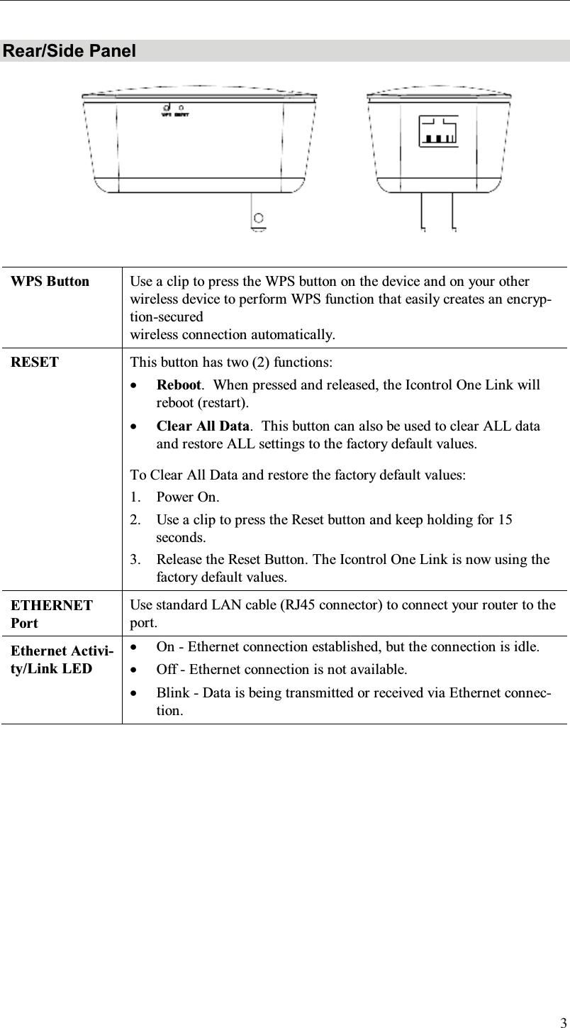
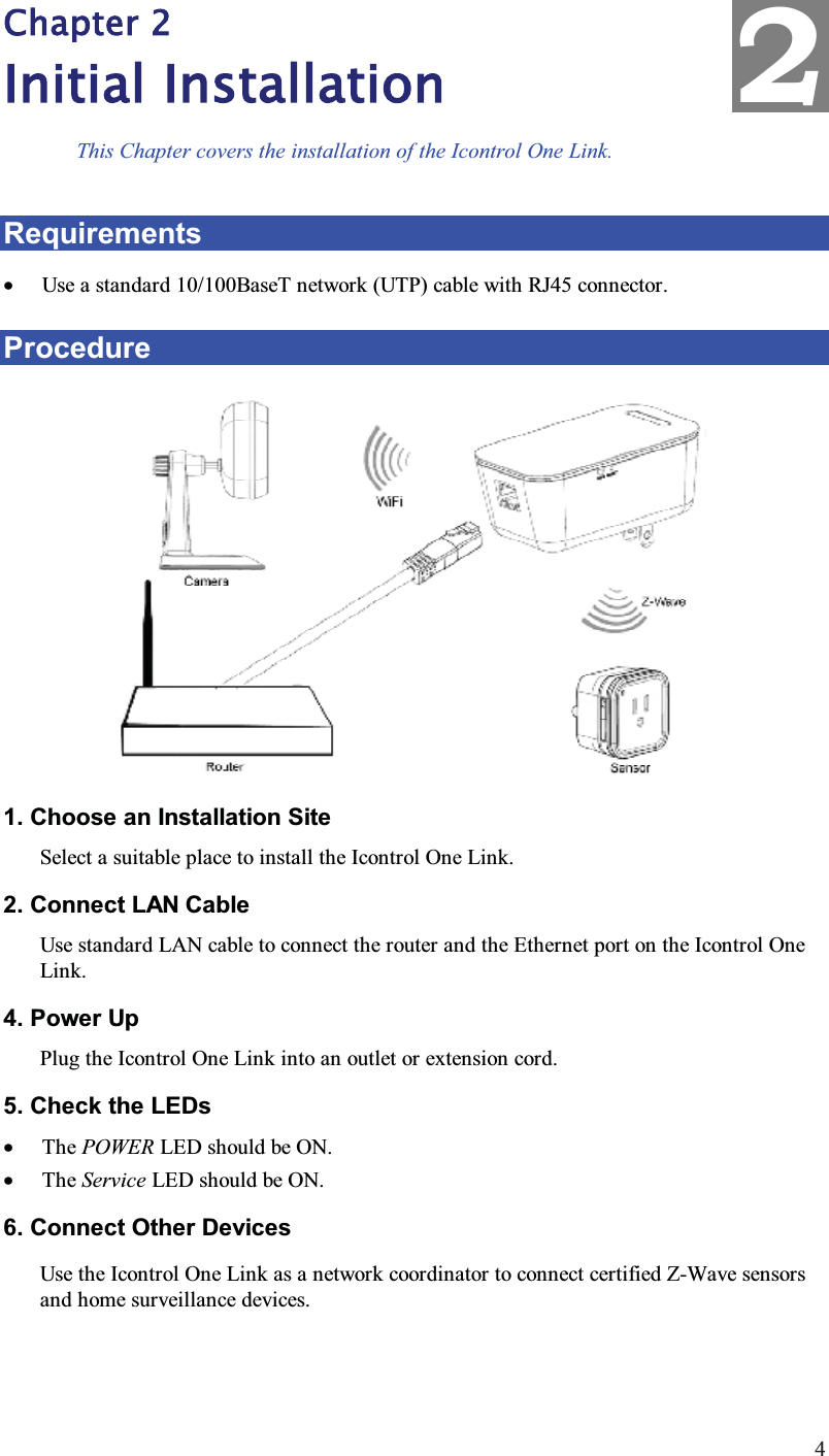
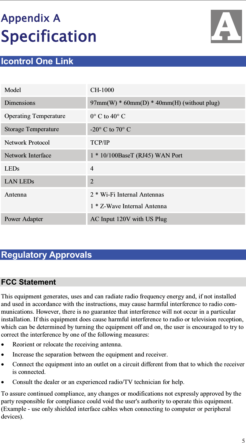
CH1000 User Manual
User Manual
Navigation menu
Upload a User Manual
Namespaces
Wiki Guide
HTML
PDF
Info
Views
User Manual
Discussion / Help
Navigation