iControl Networks CH1000 Icontrol One Link User Manual QIG NA301P draft V1 1 0416
iControl Networks Inc. Icontrol One Link QIG NA301P draft V1 1 0416
User Manual
i
Icontrol One Link
User Guide
CH-1000

ii
Table of Contents
CHAPTER 1 INTRODUCTION ......................................................................................... 1
Package Contents.......................................................................................................... 1
Features......................................................................................................................... 1
LEDs ............................................................................................................................. 2
CHAPTER 2 INITIAL INSTALLATION........................................................................... 4
Requirements................................................................................................................ 4
Procedure...................................................................................................................... 4
APPENDIX A SPECIFICATION ........................................................................................ 5
Icontrol One Link ......................................................................................................... 5
Regulatory Approvals ................................................................................................... 5
Copyright ©2015. All Rights Reserved.
Document Version: 1.1
All trademarks and trade names are the properties of their respective owners.

1
Chapter 1
Introduction
This Chapter provides an overview of the Icontrol One Link's features and
capabilities.
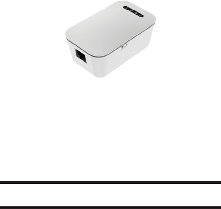
Congratulations on the purchase of your new Icontrol One Link. This device is a primary
controller and gateway, which includes Wi-Fi and Z-Wave home automation radios, provid-
ing connectivity to security systems and devices (including cameras and sensors).
Package Contents
The following items should be included:
•The Icontrol One Link Unit x 1
•Ethernet Cable x 1
•Quick Installation Guide
If any of the above items are damaged or missing, please contact your dealer immediately.
Features
•MT7620A processor with128MB Flash and 128MB SDRAM
•One Ethernet port with RJ45 connector
•Front panel LEDs
•Z-Wave transceiver
•WPS button
•Reset button
•AC power plug (US)
•Internal antenna for Wi-Fi and Z-Wave
1
2
LEDs
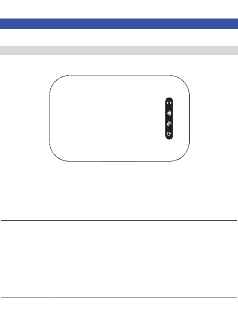
Top-mounted LEDs
The Icontrol One Link has four LEDs.
Service •On (Green) - The CPE device is activated in iControl network.
•Off - The CPE device is not activated in iControl network.
•Flashing - The CPE device can not communicated with iControl
network.
Wi-Fi •On - Wi-Fi device attached.
•Off - Wi-Fi connection is not available or no Wi-Fi device at-
tached.
•Flashing - WPS function is activated.
Z-Wave •On (Green) - Z-Wave devices attached.
•Off - Z-Wave function disabled, or no Z-Wave devices attached.
•Flashing - Learn/exclusion/inclusion mode on.
POWER •On (Green) - Power On/Normal operation
•Off -PowerOff
•Flashing - Booting or Firmware upgrade.
3
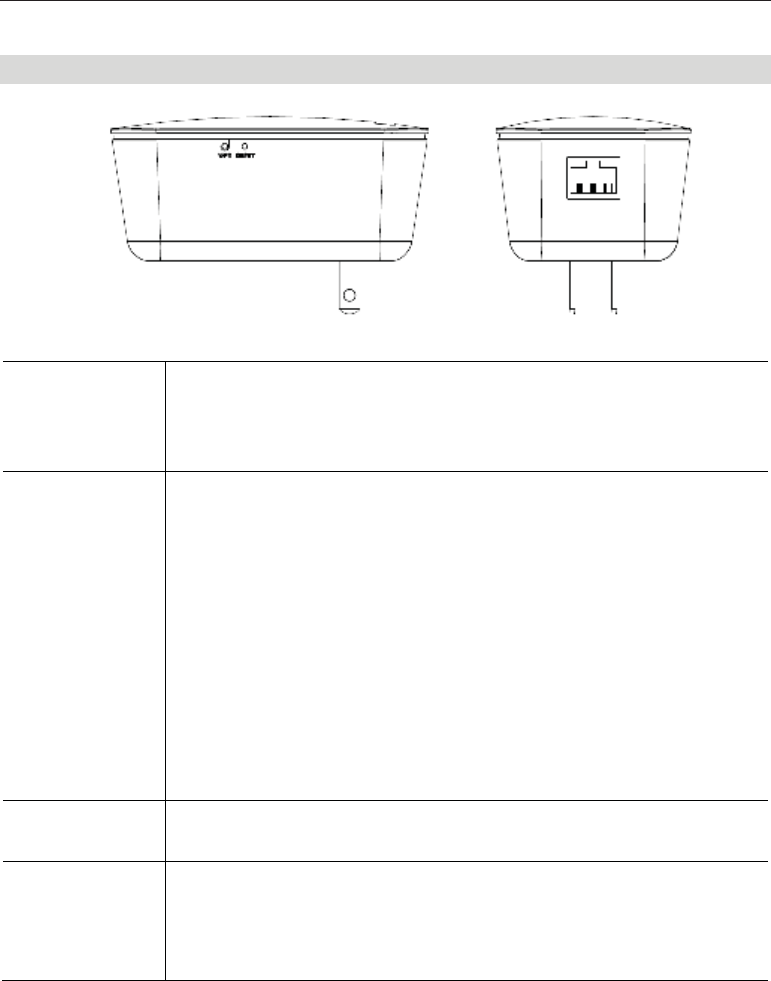
Rear/Side Panel
WPS Button Use a clip to press the WPS button on the device and on your other
wireless device to perform WPS function that easily creates an encryp-
tion-secured
wireless connection automatically.
RESET This button has two (2) functions:
•Reboot. When pressed and released, the Icontrol One Link will
reboot (restart).
•Clear All Data. This button can also be used to clear ALL data
and restore ALL settings to the factory default values.
To Clear All Data and restore the factory default values:
1. Power On.
2. Use a clip to press the Reset button and keep holding for 15
seconds.
3. Release the Reset Button. The Icontrol One Link is now using the
factory default values.
ETHERNET
Port
Use standard LAN cable (RJ45 connector) to connect your router to the
port.
Ethernet Activi-
ty/Link LED
•On - Ethernet connection established, but the connection is idle.
•Off - Ethernet connection is not available.
•Blink - Data is being transmitted or received via Ethernet connec-
tion.
4
Chapter 2
Initial Installation
This Chapter covers the installation of the Icontrol One Link.
Requirements
•Use a standard 10/100BaseT network (UTP) cable with RJ45 connector.
Procedure
1. Choose an Installation Site
Select a suitable place to install the Icontrol One Link.
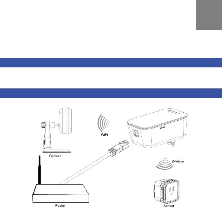
2. Connect LAN Cable
Use standard LAN cable to connect the router and the Ethernet port on the Icontrol One
Link.
4. Power Up
Plug the Icontrol One Link into an outlet or extension cord.
5. Check the LEDs
•The POWER LED should be ON.
•The Service LED should be ON.
6. Connect Other Devices
Use the Icontrol One Link as a network coordinator to connect certified Z-Wave sensors
and home surveillance devices.
2

5
Appendix A
Specification
Icontrol One Link
Model CH-1000
Dimensions 97mm(W) * 60mm(D) * 40mm(H) (without plug)
Operating Temperature 0°Cto40°C
Storage Temperature -20°Cto70°C
Network Protocol TCP/IP
Network Interface 1 * 10/100BaseT (RJ45) WAN Port
LEDs 4
LAN LEDs 2
Antenna 2 * Wi-Fi Internal Antennas
1 * Z-Wave Internal Antenna
Power Adapter AC Input 120V with US Plug
Regulatory Approvals
FCC Statement
This equipment generates, uses and can radiate radio frequency energy and, if not installed
and used in accordance with the instructions, may cause harmful interference to radio com-
munications. However, there is no guarantee that interference will not occur in a particular
installation. If this equipment does cause harmful interference to radio or television reception,
which can be determined by turning the equipment off and on, the user is encouraged to try to
correct the interference by one of the following measures:
•Reorient or relocate the receiving antenna.
•Increase the separation between the equipment and receiver.
•Connect the equipment into an outlet on a circuit different from that to which the receiver
is connected.
•Consult the dealer or an experienced radio/TV technician for help.
To assure continued compliance, any changes or modifications not expressly approved by the
party responsible for compliance could void the user's authority to operate this equipment.
(Example - use only shielded interface cables when connecting to computer or peripheral
devices).
A

6
FCC Radiation Exposure Statement
This equipment complies with FCC RF radiation exposure limits set forth for an uncontrolled
environment. This equipment should be installed and operated with a minimum distance of 20
centimeters between the radiator and your body.
This device complies with Part 15 of the FCC Rules. Operation is subject to the following two
conditions:
(1) This device may not cause harmful interference, and
(2) This device must accept any interference received, including interference that may cause
undesired operation.
This transmitter must not be co-located or operating in conjunction with any other antenna or
transmitter.