iControl Networks SMCTB01Z Zigbee Alarm Takeover Module User Manual SMCMT02 Z Motion Sensor Quick Start Guide
iControl Networks, Inc. Zigbee Alarm Takeover Module SMCMT02 Z Motion Sensor Quick Start Guide
UserManual.wiki
>
iControl Networks
>
SMCTB01Z User Manual
User manual
Navigation menu
Upload a User Manual
Namespaces
Wiki Guide
HTML
PDF
Info
Views
User Manual
Discussion / Help
Navigation
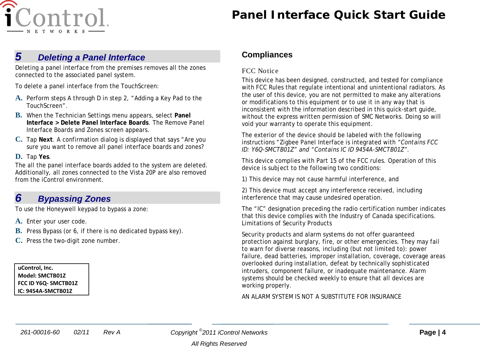
![iControl OpenHome™ Converge Panel Interface Quick Start Guide Congratulations on purchasing your Panel Interface. The iControl Networks, Inc. OpenHome Converge Panel Interface is a professional state-of-the-art device that allows you to manage your Honeywell Vista 20P system and sensors from your TouchScreen. For UL/ETL applications: • The Panel Interface module MUST be located behind the Vista 20P keypad and installed within an industry standard PVC box. This box must be designed and listed for use with non-metallic sheathed cable in accordance with Article 314 of the National Electrical Code®. All boxes must be listed to UL514C. This box is not provided as part of the installation kit. It must be provided by the installer. • The Panel Interface module must be installed in the same room as the alarm control panel and keypad. 1 Installation Guidelines Important: The Panel Interface module must be installed at least 0.3 inches (0.8 cm) away from any metal structure and be used at distances of more than 8 inches (20 cm) away from the user. A. Prior to installation of the Panel Interface module, each Vista 20P keypad must be programmed to unique keypad address of 16-23, or to the non-addressable mode (31). Do the following to change the address of the Vista 20P keypad: 1. Enter address mode. 2. Power up the keypad. 3. Within 60 seconds of power-up, press and hold down the [1] and [3] keys at the same time for 3 seconds. Note: If unable to enter the Address mode, power up and try again. The current keypad address is displayed. The cursor is under the tens digit. Note: If 10 seconds have passed with no key entry, the keypad automatically exits address mode. You must power down, power up and start address mode again. B. Remove AC power and the red and flying leads from the battery located in the Vista 20P alarm panel. C. Remove the existing Vista20P keypad(s) from the mounting surface. D. Cut the cable that connects the Vista 20P keypad to the alarm panel using care to not allow the wire coming from the alarm panel to fall back into the wall. E. Strip cable ends and attach the cut ends of the cable to the iControl Panel Interface as illustrated. Connect cable wires based on their color as in the diagram above. The wire colors identify their functions:](https://usermanual.wiki/iControl-Networks/SMCTB01Z/User-Guide-1431749-Page-1.png)
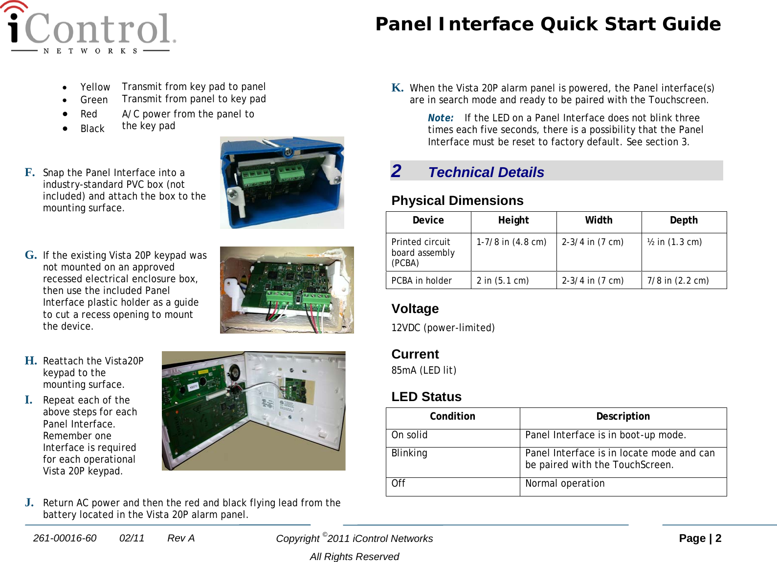
![Panel Interface Quick Start Guide Copyright ©2011 iControl Networks Page | 3 All Rights Reserved 261-00016-60 02/11 Rev A 3 Setting the Panel Interface to Factory Default Perform the following steps within 10 minutes of power-up to set the Panel Interface to factory default. A. Press and hold the [1] and [*] keys at the same time until the keypad beeps. B. Press and hold the [3] and [#] keys at the same time until the keypad beeps. C. Press and hold the [1] and [*] keys at the same time until the keypad beeps. D. Press and hold the [3] and [#] keys at the same time until the keypad beeps. The keypad should then display either “Welcome to uControl SMA” or “iControl OpenHome.” If so, the Panel Interface has been defaulted. 4 Adding a Panel Interface A. From the TouchScreen Home screen, tap the Settings app. B. When the TouchScreen Keypad screen appears, tap the numbers to enter the Installer keypad code (this code is the same for all TouchScreens installed by your company). C. When the Technician keyboard pad appears, enter your Technician ID and touch Done. D. When the Technician Settings menu appears, tap Home Devices. The Home Devices menu appears. E. Tap Panel Interface > Add Panel Interface Boards. The Locating Key Pads screen appears. The Panel Interface can be located only within the first 90 seconds of being powered up. The Alarm Panel Alphanumeric Keypad should be displaying “Scanning for Network.” If not, then press any button on the keypad to restart the process or cycle power to the Panel Interface. F. Touch Next, and the system scans the premises for Panel Interfaces that can be added, which must meet the following requirements: - Defaulted - Not currently paired with another TouchScreen. - In Search Mode (LED blinking 3 times every 5 seconds) G. Follow the system prompts to complete the add process and pair the key pad with the TouchScreen. Note: If no available Panel Interfaces are found, tap Done to return to the Technician Settings menu without adding. H. When all the Panel Interfaces are found, tap Next. The TouchScreen begins locating the Zones connected to the Panel system. This operation can take a few minutes. When all the zones are found, an icon for each is displayed in the Configure Panel Interface Sensors screen. I. Tap a Zone icon to configure the following: o Display icon (such as a window or door icon) o Zone Function (Entry/Exit, Perimeter, or 24-Hour Inform) o Zone Label (a user-defined identifier for the zone) J. After all the zones are configured, tap Next. Congratulations! You have successfully added your panel interfaces. The Vista 20P system key pad can now be used to enter key pad codes to disarm the iControl OpenHome Converge system during Entry delay. Additionally, the key pad information screen displays messages from the iControl system.](https://usermanual.wiki/iControl-Networks/SMCTB01Z/User-Guide-1431749-Page-3.png)