iControl Networks SMCTB01Z Zigbee Alarm Takeover Module User Manual SMCMT02 Z Motion Sensor Quick Start Guide
iControl Networks, Inc. Zigbee Alarm Takeover Module SMCMT02 Z Motion Sensor Quick Start Guide
User manual
iControl OpenHome™ Converge Panel Interface
Quick Start Guide
Congratulations on purchasing your Panel Interface.
The iControl Networks, Inc. OpenHome Converge Panel Interface is a professional state-of-the-art device that allows you to manage your
Honeywell Vista 20P system and sensors from your TouchScreen.
For UL/ETL applications:
• The Panel Interface module MUST be located
behind the Vista 20P keypad and installed
within an industry standard PVC box. This box
must be designed and listed for use with non-
metallic sheathed cable in accordance with
Article 314 of the National Electrical Code®.
All boxes must be listed to UL514C. This box is
not provided as part of the installation kit. It
must be provided by the installer.
• The Panel Interface module must be installed in the same room as
the alarm control panel and keypad.
1 Installation Guidelines
Important: The Panel Interface module must be installed at least 0.3
inches (0.8 cm) away from any metal structure and be used at
distances of more than 8 inches (20 cm) away from the user.
A. Prior to installation of the Panel Interface module, each Vista 20P
keypad must be programmed to unique keypad address of 16-23, or
to the non-addressable mode (31).
Do the following to change the address of the Vista 20P keypad:
1. Enter address mode.
2. Power up the keypad.
3. Within 60 seconds of power-up, press and hold down the [1]
and [3] keys at the same time for 3 seconds.
Note: If unable to enter the Address mode, power up and try
again.
The current keypad address is displayed. The cursor is under the
tens digit.
Note: If 10 seconds have passed with no key entry, the
keypad automatically exits address mode. You must power
down, power up and start address mode again.
B. Remove AC power and the red and flying leads from the battery
located in the Vista 20P alarm panel.
C. Remove the existing Vista20P keypad(s) from the mounting surface.
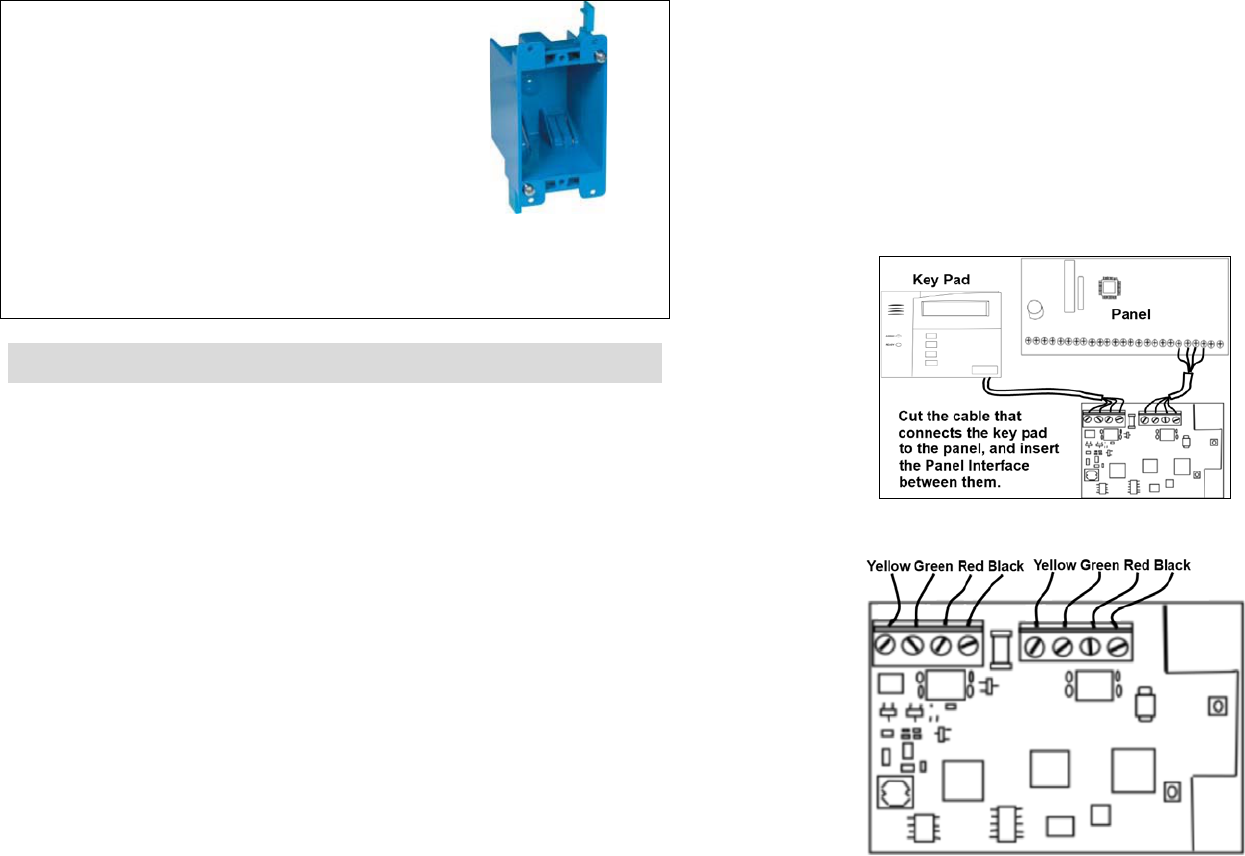
D. Cut the cable that connects the Vista 20P keypad to the alarm
panel using care to not allow the wire coming from the alarm panel
to fall back into the wall.
E. Strip cable ends and attach the cut ends of the cable to the
iControl Panel Interface as illustrated.
Connect cable wires based on their color as in the diagram above.
The wire colors identify their functions:
Panel Interface Quick Start Guide
Copyright ©2011 iControl Networks Page | 2
All Rights Reserved
261-00016-60 02/11 Rev A
•
Yellow
Transmit from key pad to panel
• Green Transmit from panel to key pad
•
Red
A/C power from the panel to
the key pad
•
Black
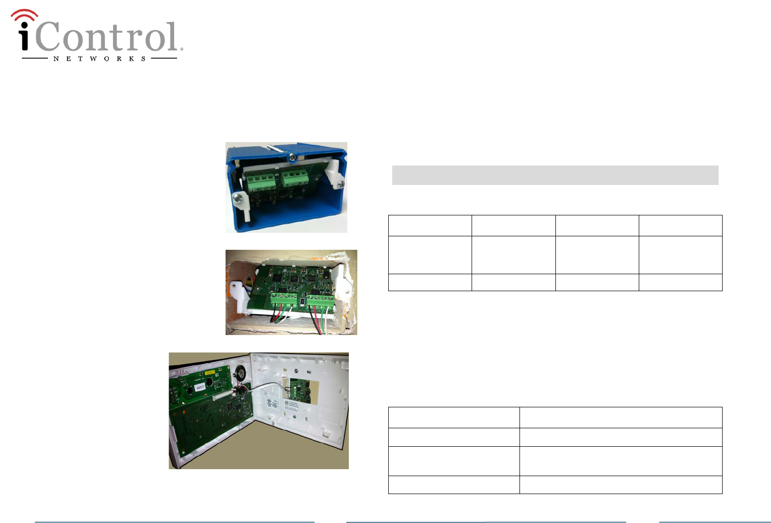
F. Snap the Panel Interface into a
industry-standard PVC box (not
included) and attach the box to the
mounting surface.
G. If the existing Vista 20P keypad was
not mounted on an approved
recessed electrical enclosure box,
then use the included Panel
Interface plastic holder as a guide
to cut a recess opening to mount
the device.
H. Reattach the Vista20P
keypad to the
mounting surface.
I. Repeat each of the
above steps for each
Panel Interface.
Remember one
Interface is required
for each operational
Vista 20P keypad.
J. Return AC power and then the red and black flying lead from the
battery located in the Vista 20P alarm panel.
K. When the Vista 20P alarm panel is powered, the Panel interface(s)
are in search mode and ready to be paired with the Touchscreen.
Note: If the LED on a Panel Interface does not blink three
times each five seconds, there is a possibility that the Panel
Interface must be reset to factory default. See section 3.
2 Technical Details
Physical Dimensions
Device Height Width Depth
Printed circuit
board assembly
(PCBA)
1-7/8 in (4.8 cm) 2-3/4 in (7 cm) ½ in (1.3 cm)
PCBA in holder 2 in (5.1 cm) 2-3/4 in (7 cm) 7/8 in (2.2 cm)
Voltage
12VDC (power-limited)
Current
85mA (LED lit)
LED Status
Condition Description
On solid
Panel Interface is in boot-up mode.
Blinking
Panel Interface is in locate mode and can
be paired with the TouchScreen.
Off
Normal operation

Panel Interface Quick Start Guide
Copyright ©2011 iControl Networks Page | 3
All Rights Reserved
261-00016-60 02/11 Rev A
3 Setting the Panel Interface to Factory
Default
Perform the following steps within 10 minutes of power-up to set the
Panel Interface to factory default.
A. Press and hold the [1] and [*] keys at the same time until the
keypad beeps.
B. Press and hold the [3] and [#] keys at the same time until the
keypad beeps.
C. Press and hold the [1] and [*] keys at the same time until the
keypad beeps.
D. Press and hold the [3] and [#] keys at the same time until the
keypad beeps.
The keypad should then display either “Welcome to uControl SMA” or
“iControl OpenHome.” If so, the Panel Interface has been defaulted.
4 Adding a Panel Interface
A. From the TouchScreen Home screen, tap the Settings app.
B. When the TouchScreen Keypad screen appears, tap the numbers to
enter the Installer keypad code (this code is the same for all
TouchScreens installed by your company).
C. When the Technician keyboard pad appears, enter your Technician
ID and touch Done.
D. When the Technician Settings menu appears, tap Home Devices.
The Home Devices menu appears.
E. Tap Panel Interface > Add Panel Interface Boards. The Locating
Key Pads screen appears.
The Panel Interface can be located only within the first 90 seconds
of being powered up. The Alarm Panel Alphanumeric Keypad should
be displaying “Scanning for Network.” If not, then press any button
on the keypad to restart the process or cycle power to the Panel
Interface.
F. Touch Next, and the system scans the premises for Panel Interfaces
that can be added, which must meet the following requirements:
- Defaulted
- Not currently paired with another TouchScreen.
- In Search Mode (LED blinking 3 times every 5 seconds)
G. Follow the system prompts to complete the add process and pair
the key pad with the TouchScreen.
Note: If no available Panel Interfaces are found, tap Done to
return to the Technician Settings menu without adding.
H. When all the Panel Interfaces are found, tap Next. The
TouchScreen begins locating the Zones connected to the Panel
system. This operation can take a few minutes. When all the zones
are found, an icon for each is displayed in the Configure Panel
Interface Sensors screen.
I. Tap a Zone icon to configure the following:
o Display icon (such as a window or door icon)
o Zone Function (Entry/Exit, Perimeter, or 24-Hour Inform)
o Zone Label (a user-defined identifier for the zone)
J. After all the zones are configured, tap Next.
Congratulations!
You have successfully added your panel interfaces. The Vista
20P system key pad can now be used to enter key pad codes
to disarm the iControl OpenHome Converge system during
Entry delay. Additionally, the key pad information screen
displays messages from the iControl system.

Panel Interface Quick Start Guide
Copyright ©2011 iControl Networks Page | 4
All Rights Reserved
261-00016-60 02/11 Rev A
5 Deleting a Panel Interface
Deleting a panel interface from the premises removes all the zones
connected to the associated panel system.
To delete a panel interface from the TouchScreen:
A. Perform steps A through D in step 2, “Adding a Key Pad to the
TouchScreen”.
B. When the Technician Settings menu appears, select Panel
Interface > Delete Panel Interface Boards. The Remove Panel
Interface Boards and Zones screen appears.
C. Tap Next. A confirmation dialog is displayed that says “Are you
sure you want to remove all panel interface boards and zones?
D. Tap Yes.
The all the panel interface boards added to the system are deleted.
Additionally, all zones connected to the Vista 20P are also removed
from the iControl environment.
6 Bypassing Zones
To use the Honeywell keypad to bypass a zone:
A. Enter your user code.
B. Press Bypass (or 6, if there is no dedicated bypass key).
C. Press the two-digit zone number.
uControl, Inc.
Model: SMCTB01Z
FCC ID Y6Q- SMCTB01Z
IC: 9454A-SMCTB01Z
Compliances
FCC Notice
This device has been designed, constructed, and tested for compliance
with FCC Rules that regulate intentional and unintentional radiators. As
the user of this device, you are not permitted to make any alterations
or modifications to this equipment or to use it in any way that is
inconsistent with the information described in this quick-start guide,
without the express written permission of SMC Networks. Doing so will
void your warranty to operate this equipment.
The exterior of the device should be labeled with the following
instructions “Zigbee Panel Interface is integrated with “Contains FCC
ID: Y6Q-SMCTB01Z” and “Contains IC ID 9454A-SMCTB01Z”.
This device complies with Part 15 of the FCC rules. Operation of this
device is subject to the following two conditions:
1) This device may not cause harmful interference, and
2) This device must accept any interference received, including
interference that may cause undesired operation.
The “IC” designation preceding the radio certification number indicates
that this device complies with the Industry of Canada specifications.
Limitations of Security Products
Security products and alarm systems do not offer guaranteed
protection against burglary, fire, or other emergencies. They may fail
to warn for diverse reasons, including (but not limited to): power
failure, dead batteries, improper installation, coverage, coverage areas
overlooked during installation, defeat by technically sophisticated
intruders, component failure, or inadequate maintenance. Alarm
systems should be checked weekly to ensure that all devices are
working properly.
AN ALARM SYSTEM IS NOT A SUBSTITUTE FOR INSURANCE

Panel Interface Quick Start Guide