lantronix WIPORTG WIRELESS EMBEDDED DEVICE SERVER User Manual users guide
lantronix WIRELESS EMBEDDED DEVICE SERVER users guide
UserManual.wiki
>
lantronix
>
WIPORTG User Manual
>
users guide
Contents
1.
integration guide
2.
users guide
3.
USERS GUIDE
users guide
Navigation menu
Upload a User Manual
Namespaces
Wiki Guide
HTML
PDF
Info
Views
User Manual
Discussion / Help
Navigation


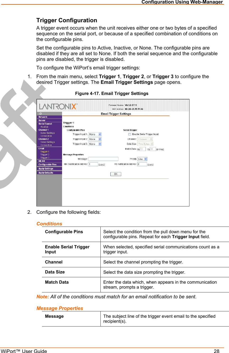
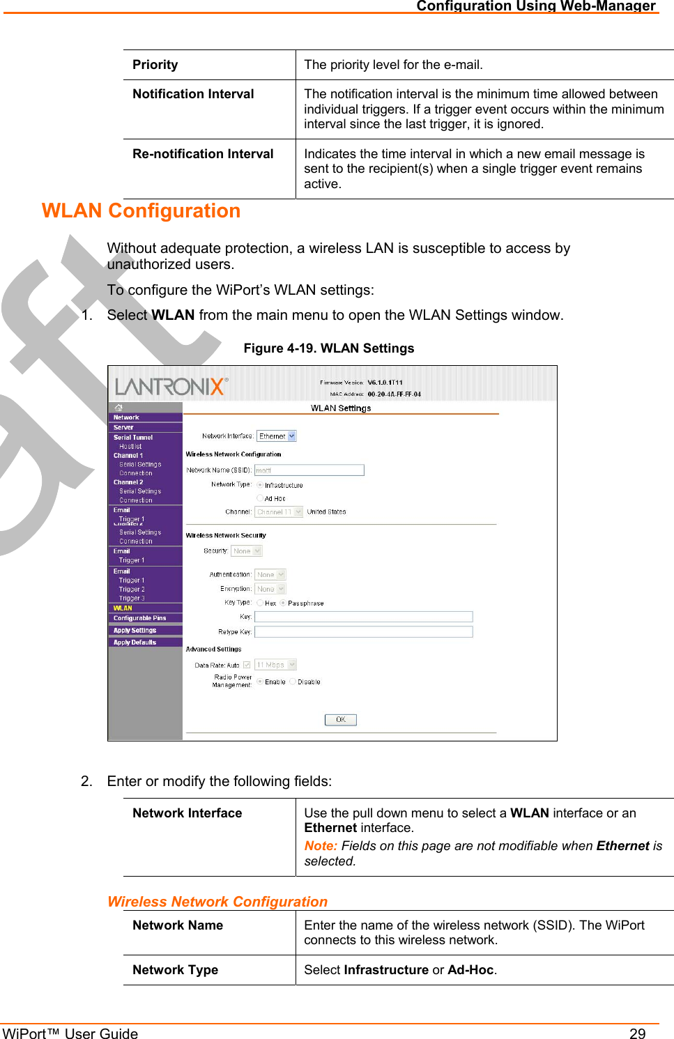
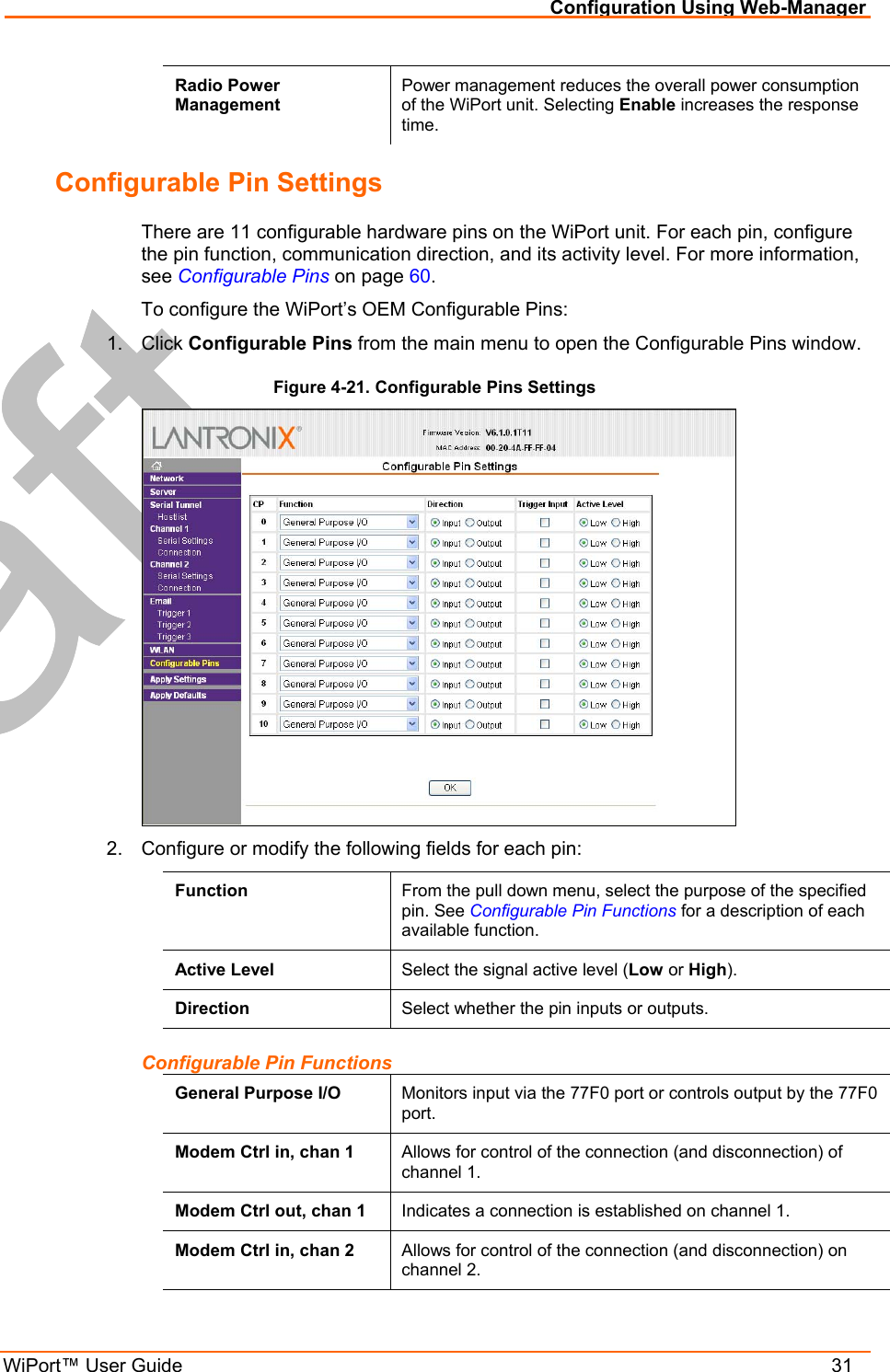
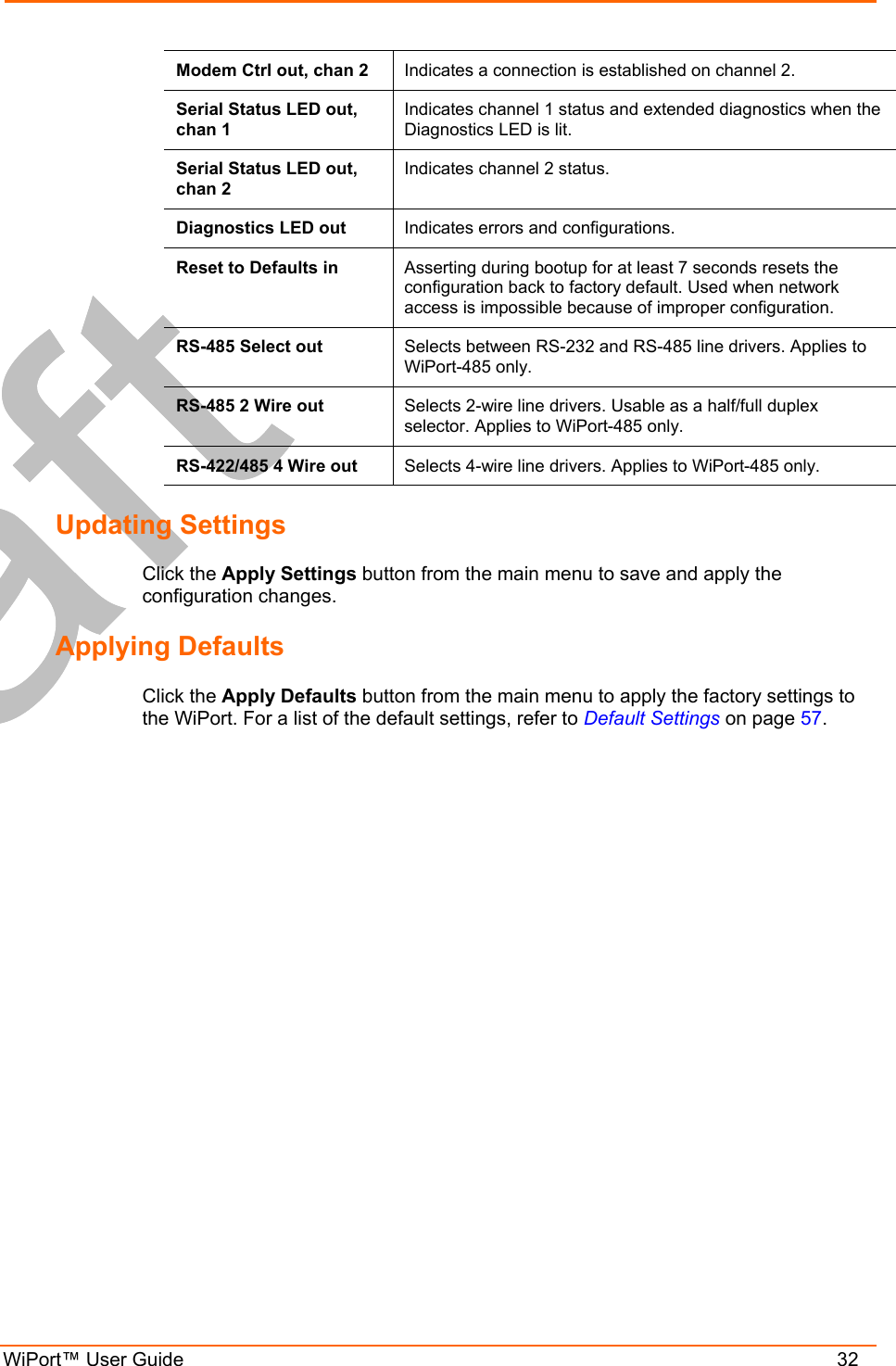
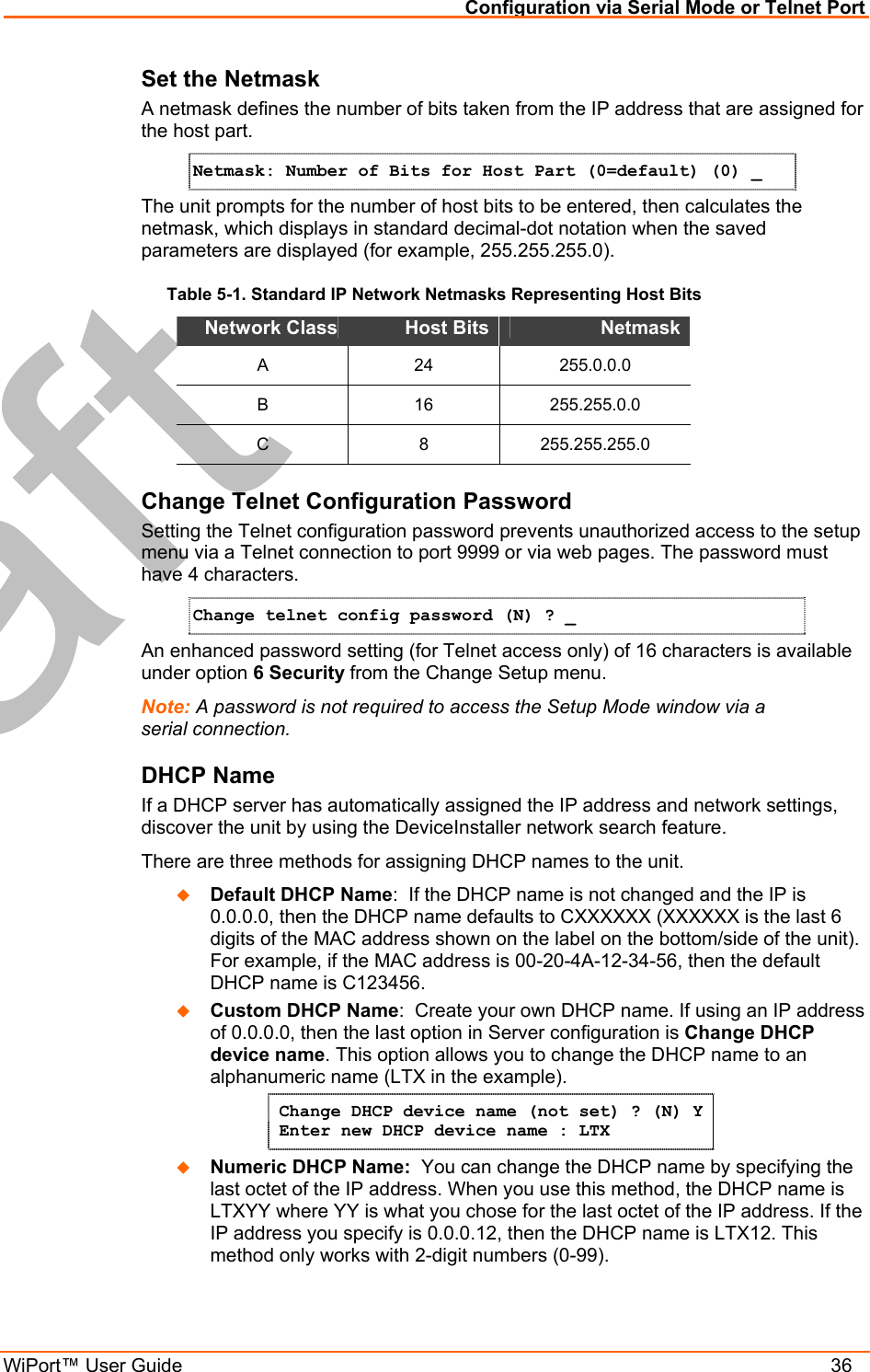
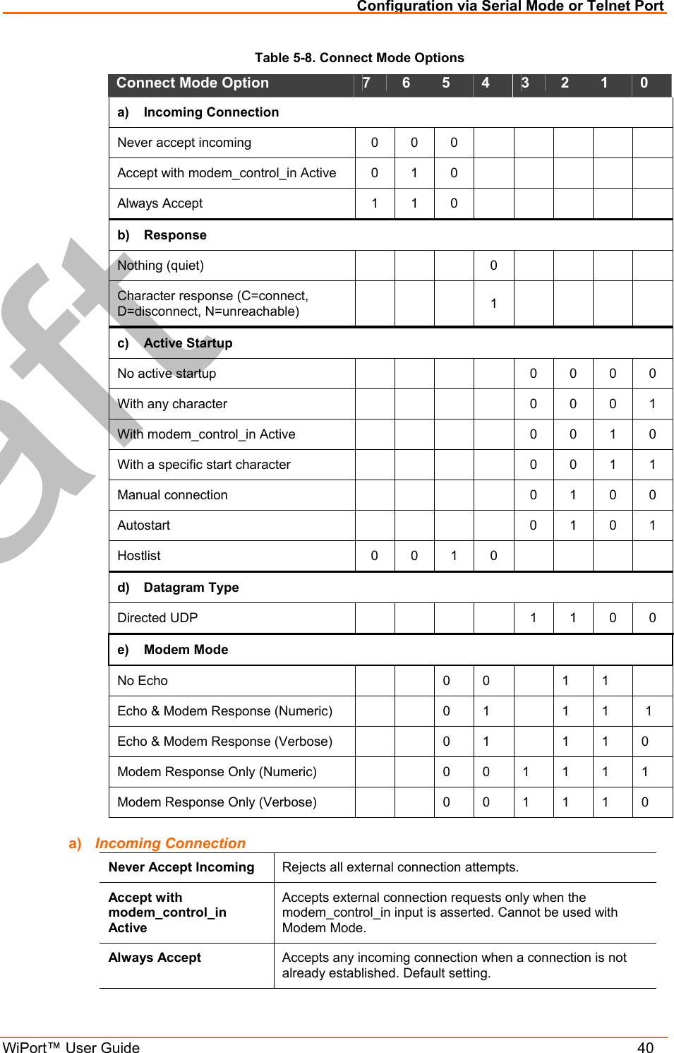
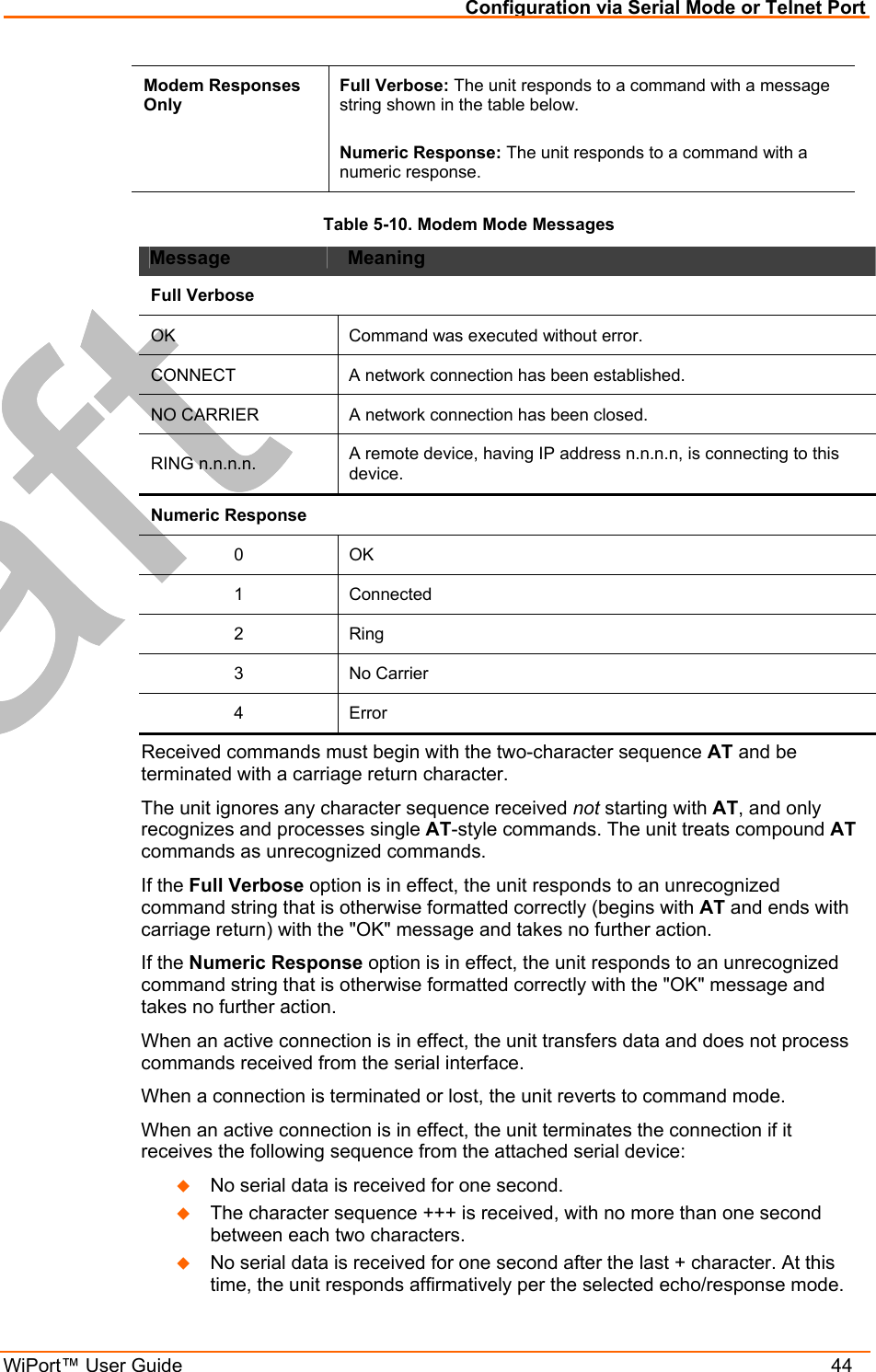
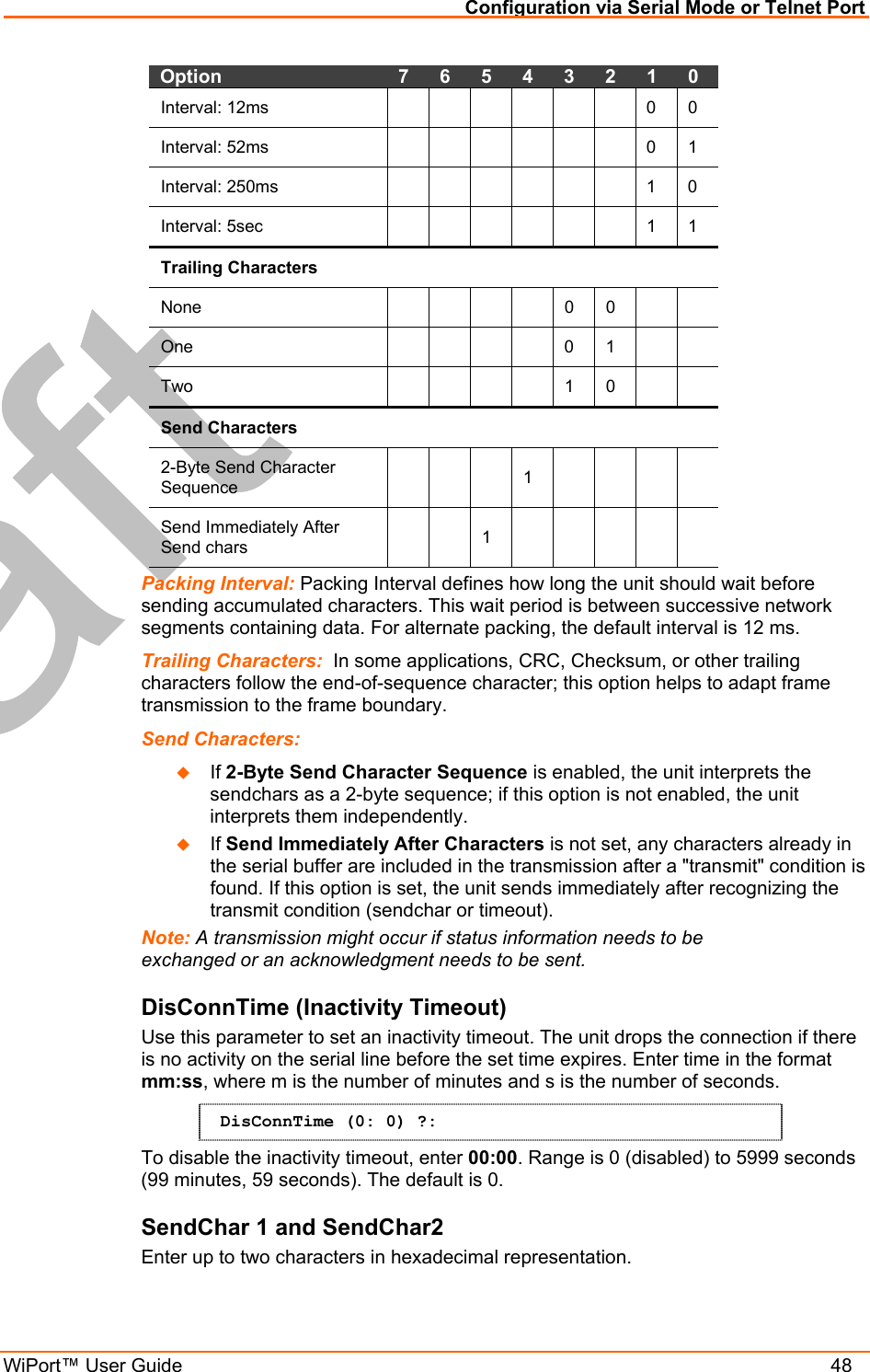
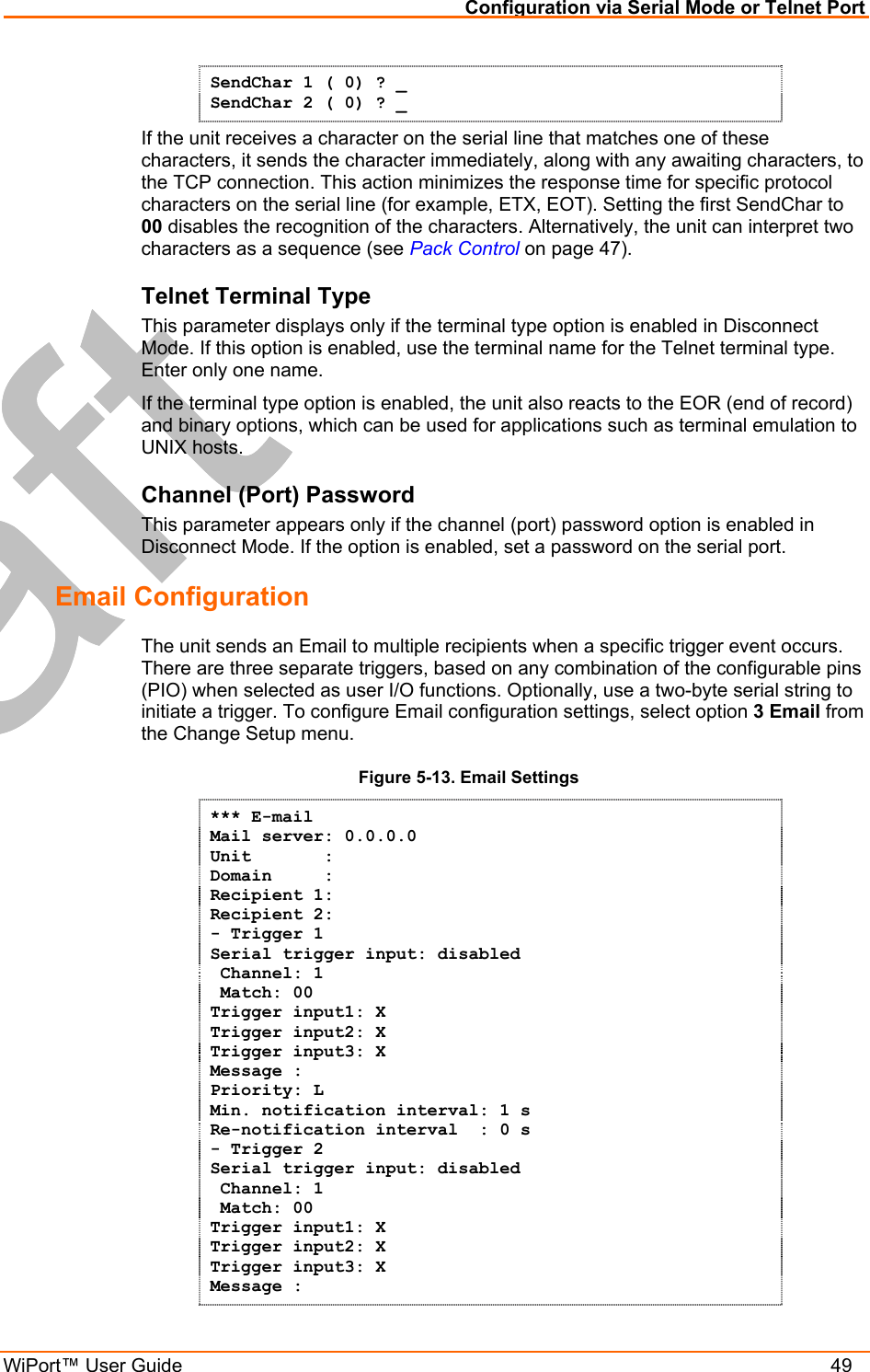
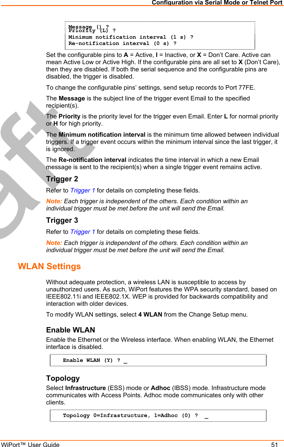
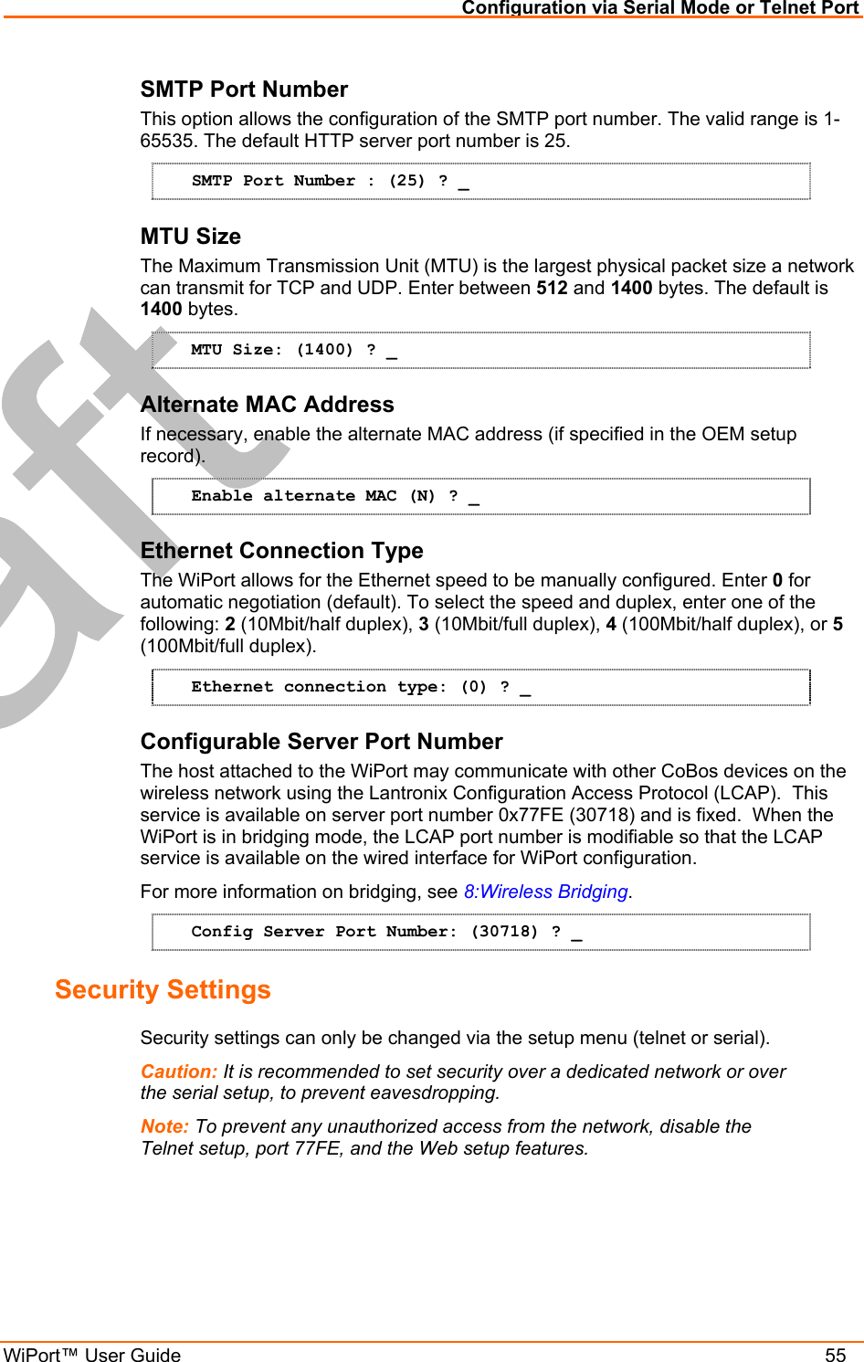
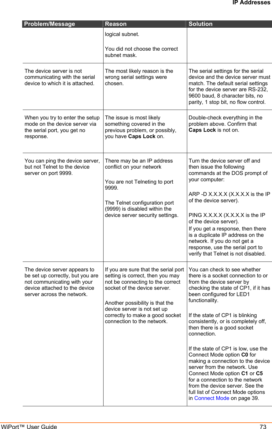
![Configuration via Serial Mode or Telnet Port WiPort™ User Guide 50 Priority: L Min. notification interval: 1 s Re-notification interval : 0 s - Trigger 3 Serial trigger input: disabled Channel: 2 Match: 00 Trigger input1: X Trigger input2: X Trigger input3: X Message : Priority: L Min. notification interval: 1 s Re-notification interval : 0 s Server (0.0.0.0) ? ( 0) _ Mail Server Enter the IP address of the mail server. Enter each 3-digit section and press Enter between each section inputted. The current value is displayed in parentheses. Mail Server (0.0.0.0) ? ( 0) _ Unit Name Enter the username used by the WiPort to send Email messages. The current value is displayed in parentheses. Spaces are not permitted. Unit name () ? _ Domain Name Enter the Email server’s domain name. The current value is displayed in parentheses. Domain name () ? _ Recipient 1 Enter the full Email address of the trigger email recipient. The current value is displayed in parentheses. Recipient 1 () ? _ Recipient 2 Enter the full Email address of the trigger email recipient. The current value is displayed in parentheses. Recipient 2 () ? _ Trigger 1 A trigger event occurs when the unit receives the specified trigger input because of a specified combination of conditions on the configurable pins. Enable serial trigger input (N) ? Trigger input1 [A/I/X] (X) ? Trigger input1 [A/I/X] (X) ? Trigger input1 [A/I/X] (X) ?](https://usermanual.wiki/lantronix/WIPORTG.users-guide/User-Guide-671300-Page-50.png)