lantronix WIPORTG WIRELESS DEVICE SERVER User Manual USERS GUIDE
lantronix WIRELESS DEVICE SERVER USERS GUIDE
UserManual.wiki
>
lantronix
>
WIPORTG User Manual
>
USERS GUIDE
Contents
1.
integration guide
2.
users guide
3.
USERS GUIDE
USERS GUIDE
Navigation menu
Upload a User Manual
Namespaces
Wiki Guide
HTML
PDF
Info
Views
User Manual
Discussion / Help
Navigation
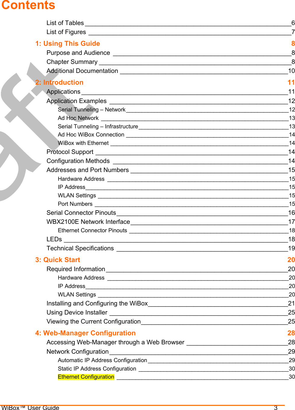

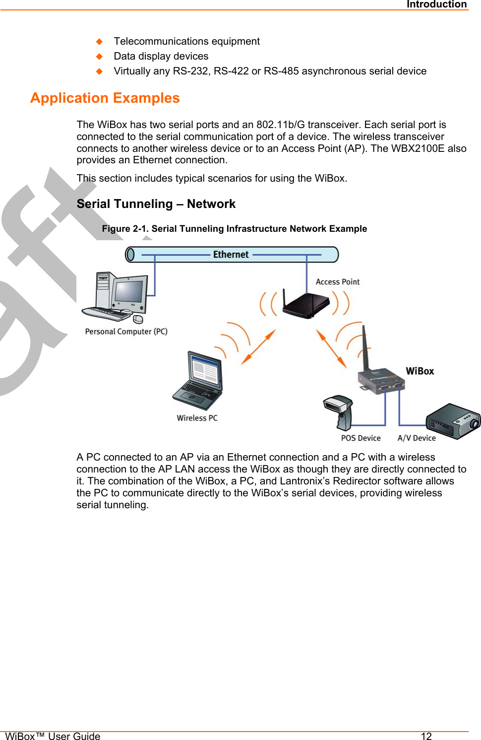
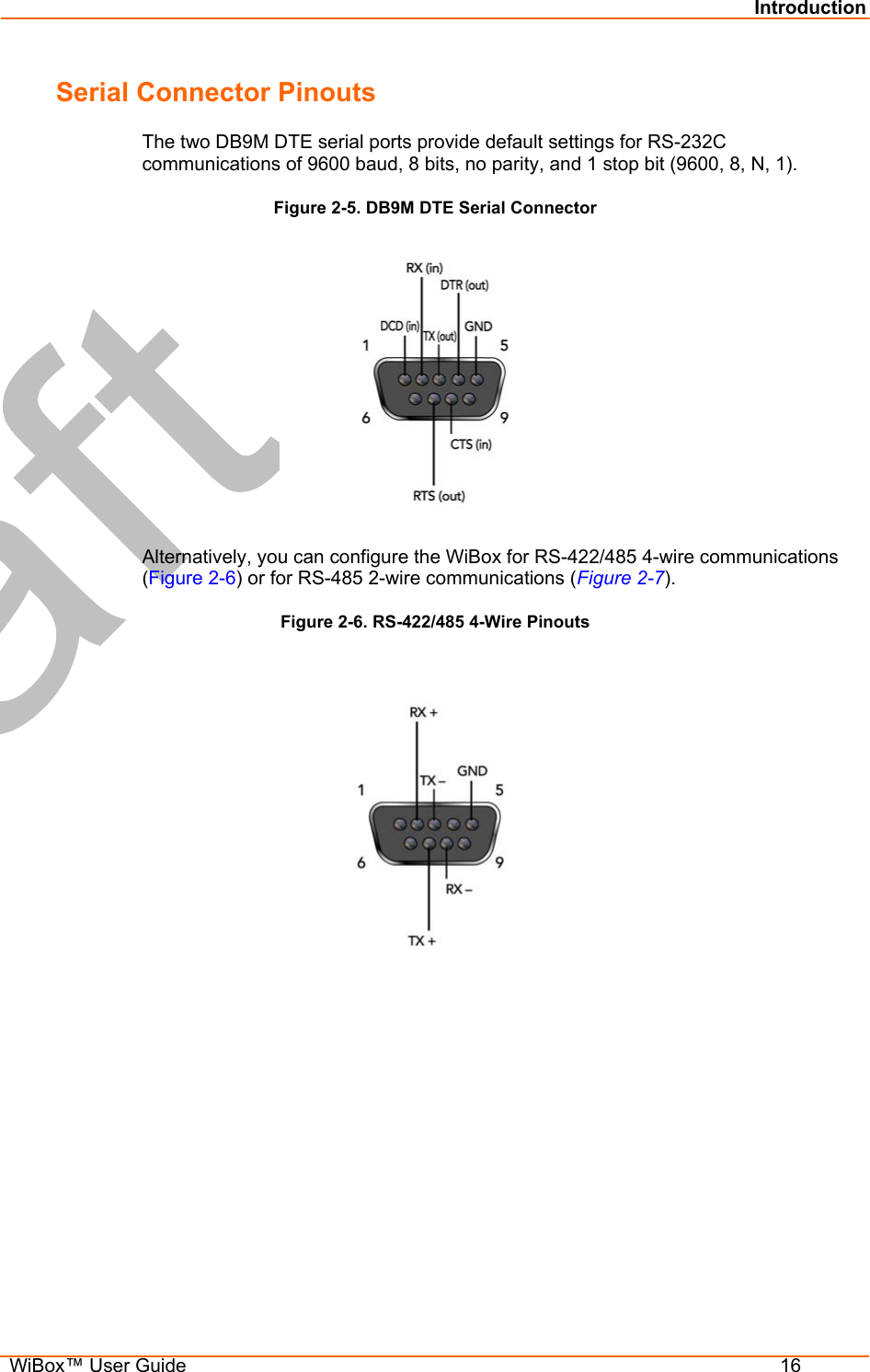

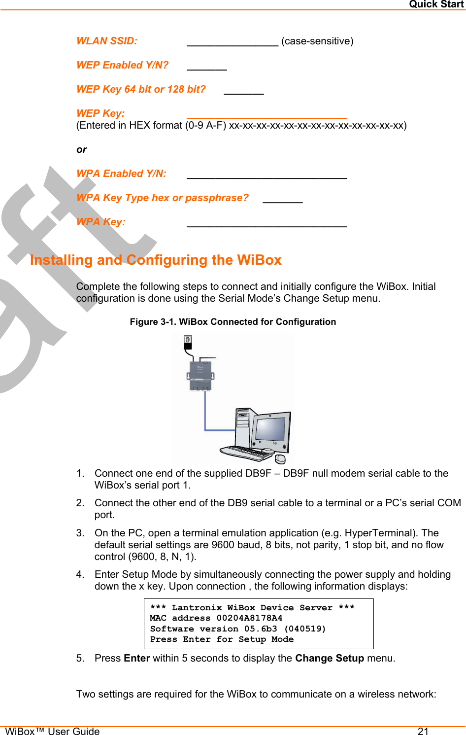
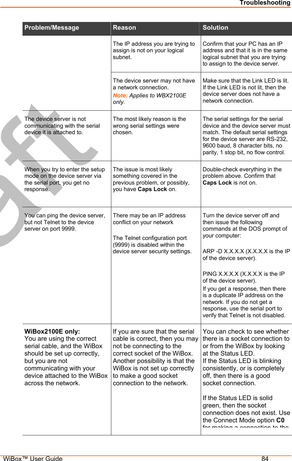
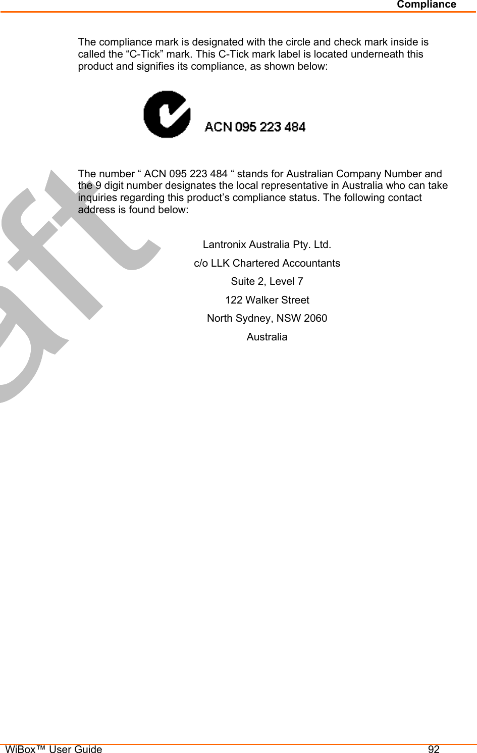
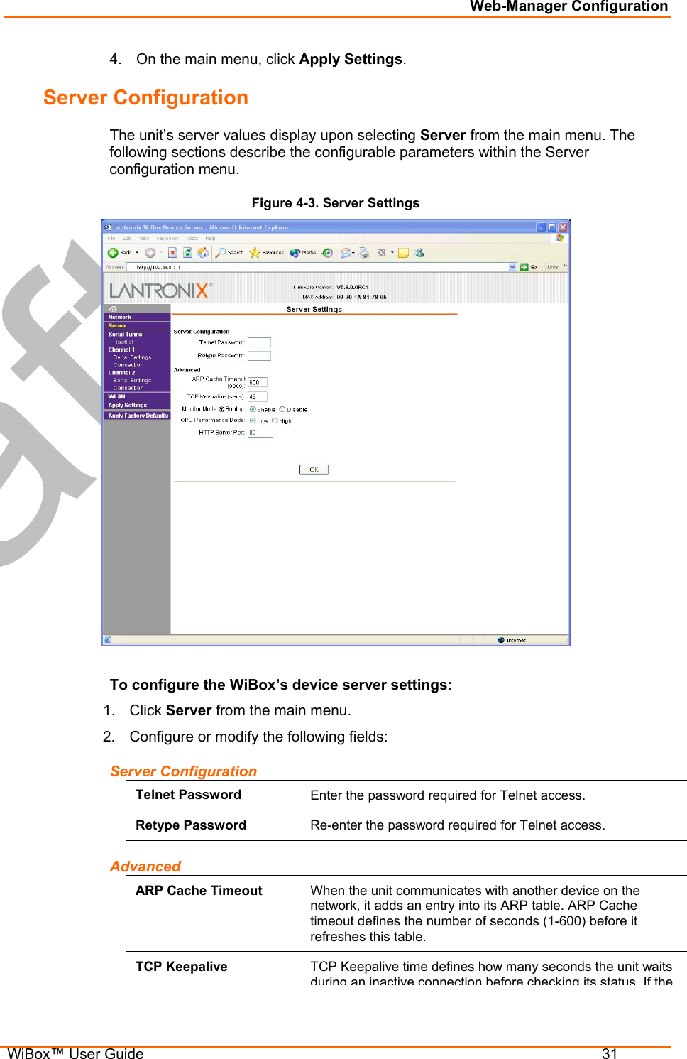
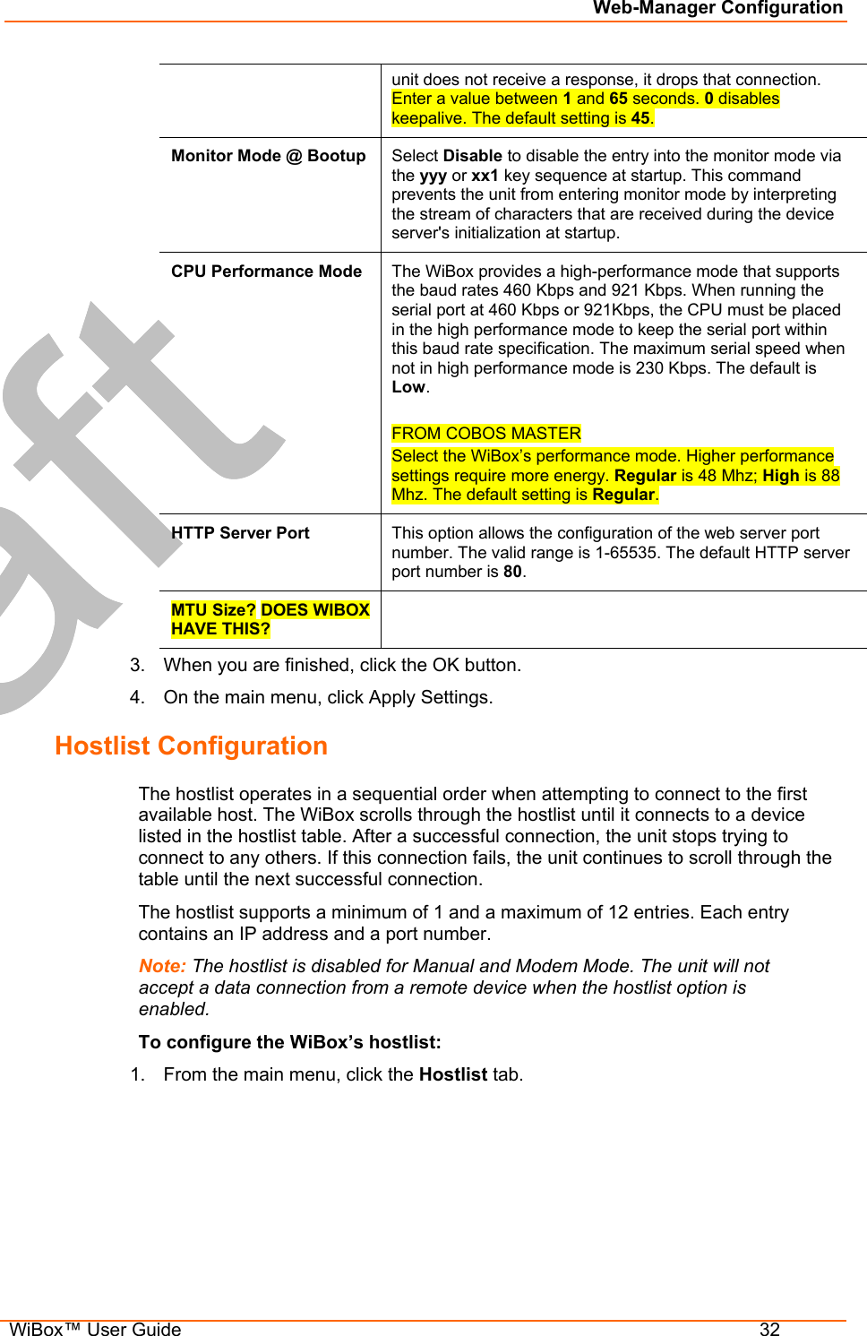
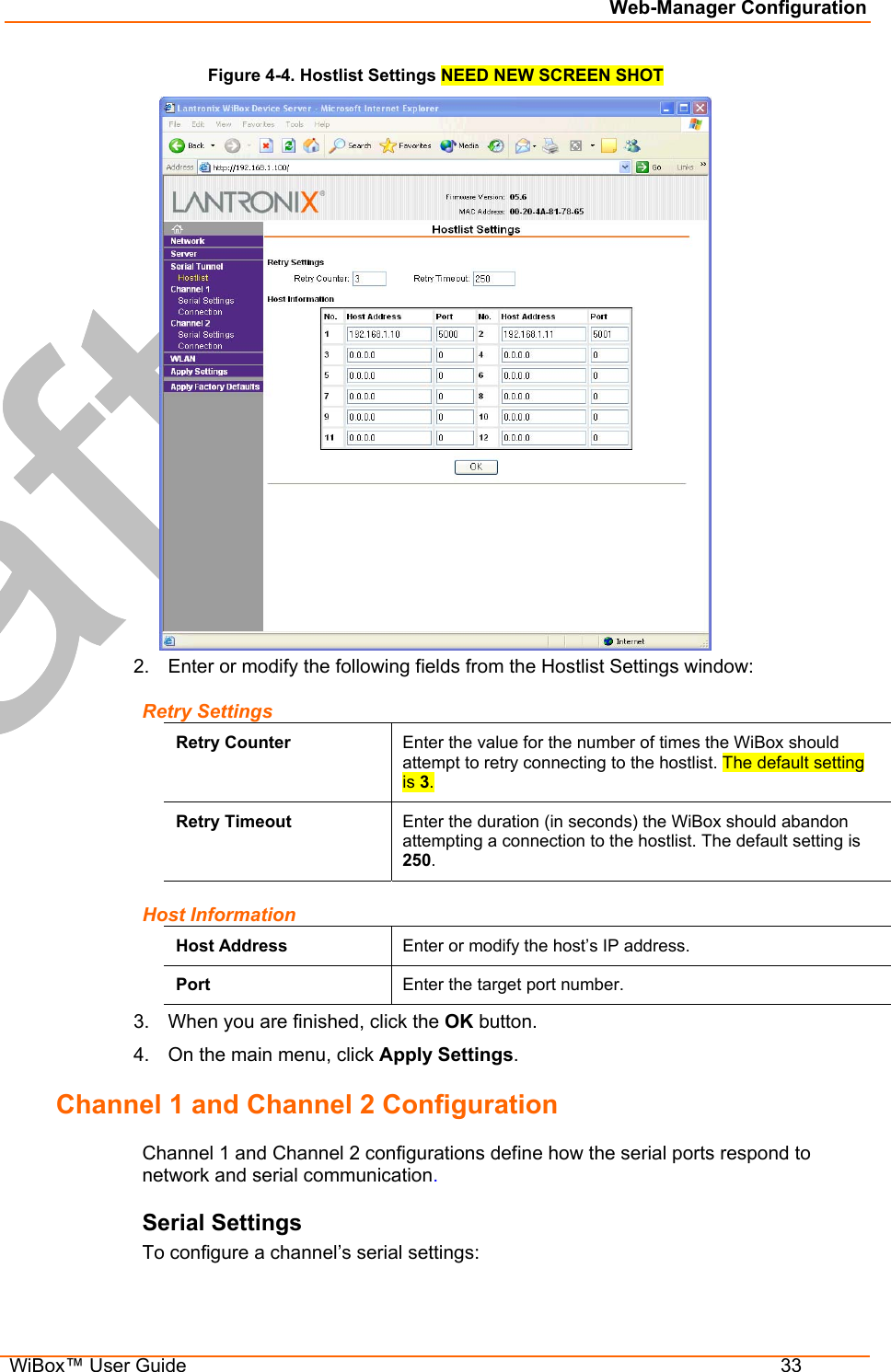
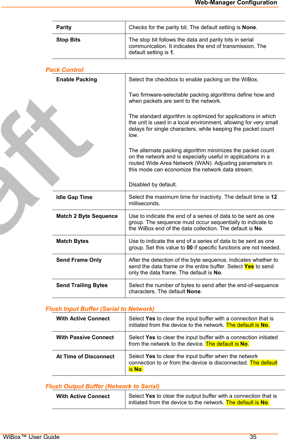
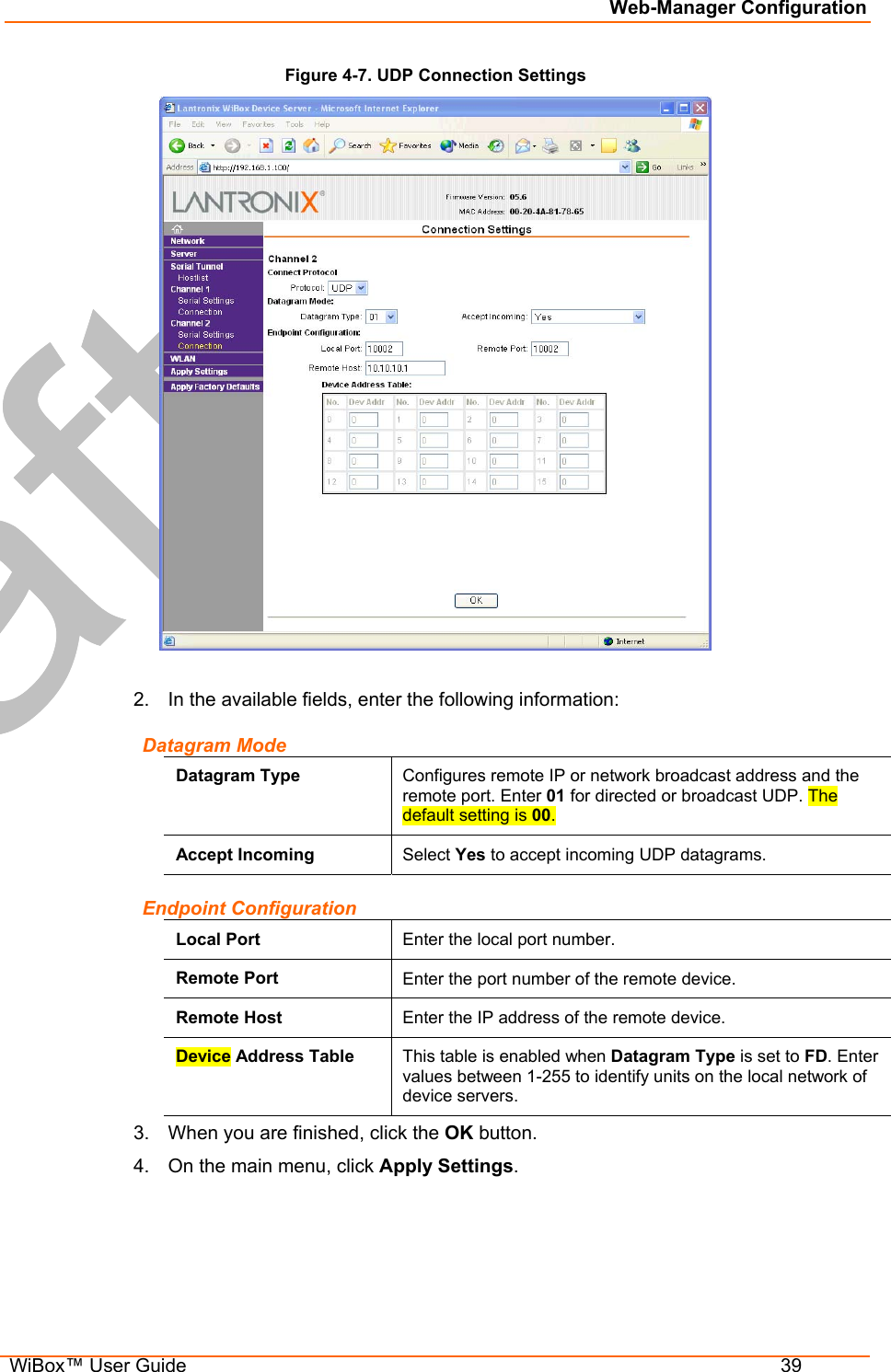
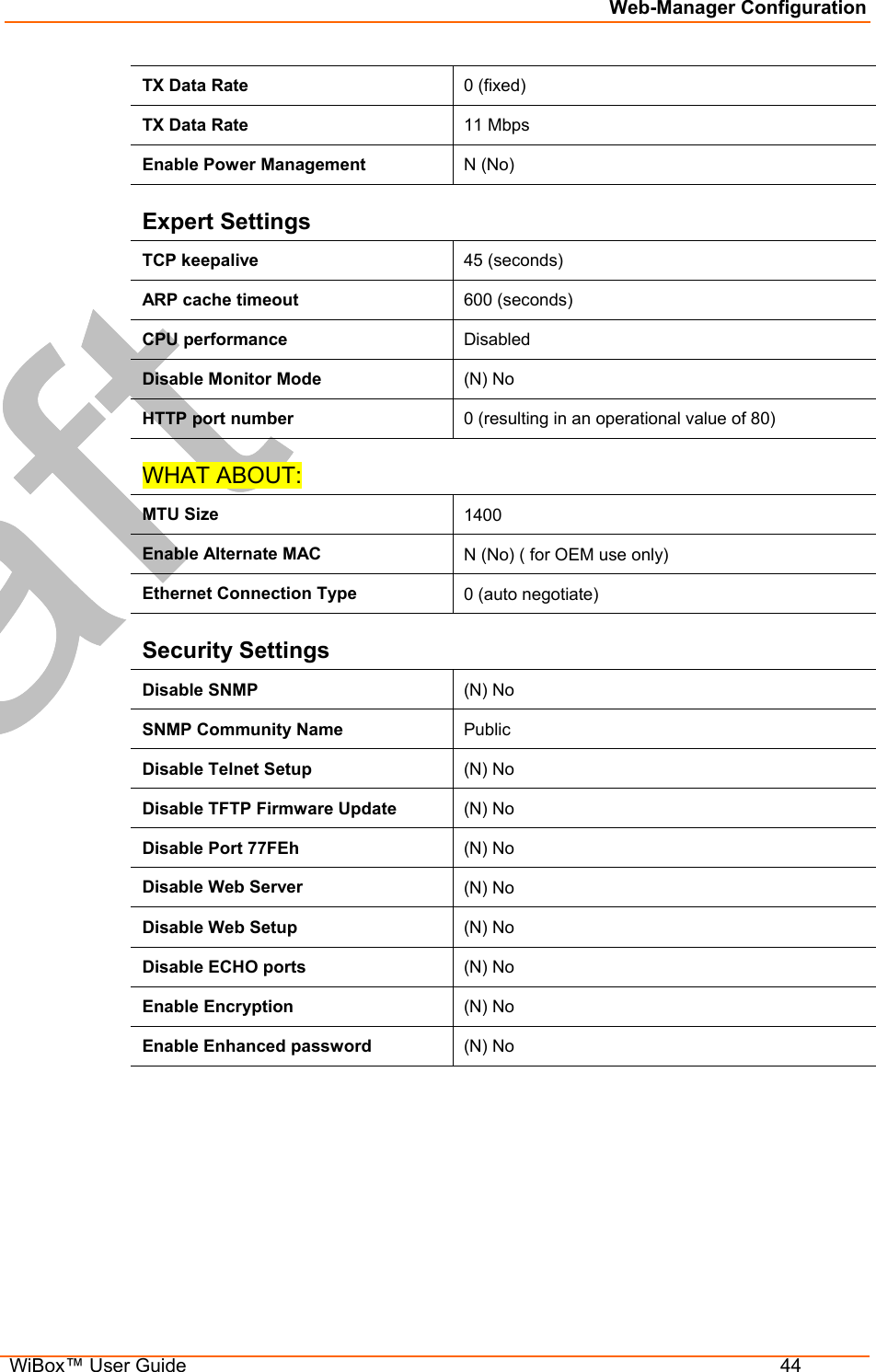
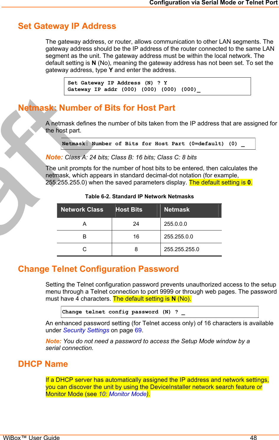
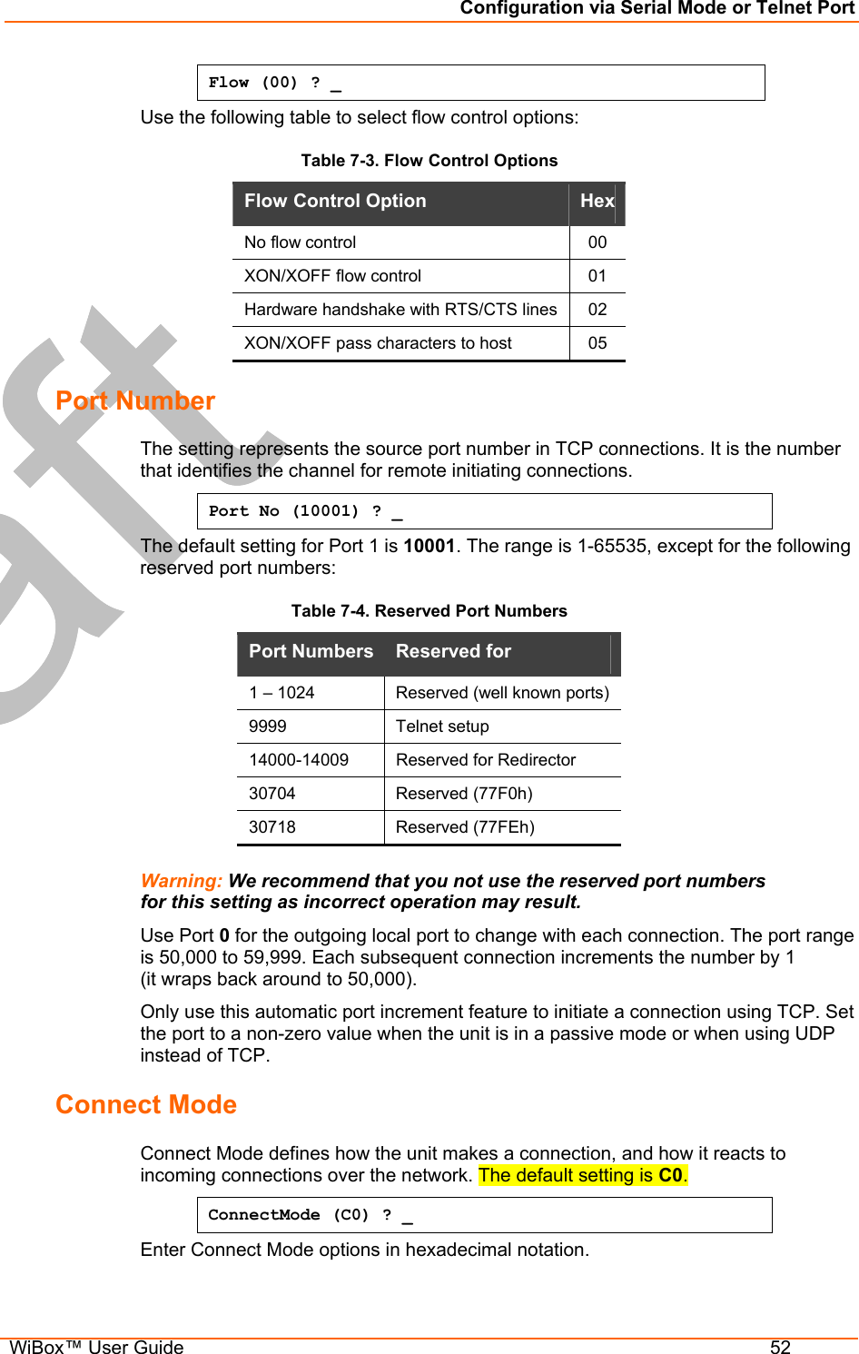
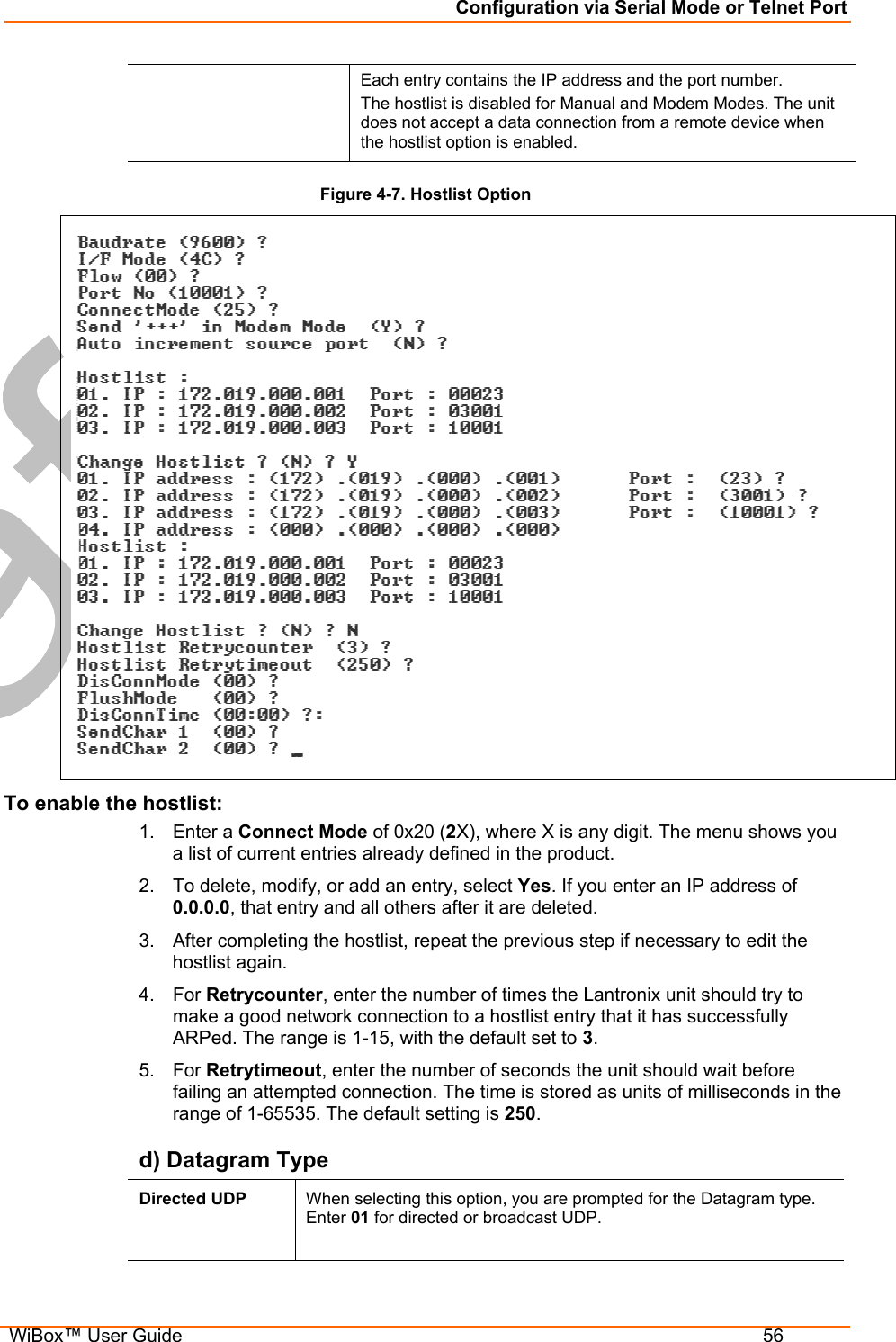
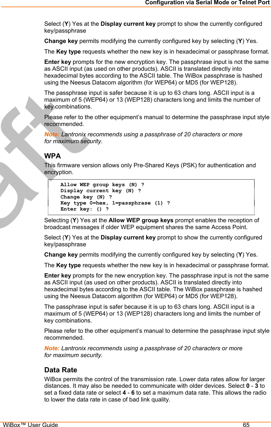
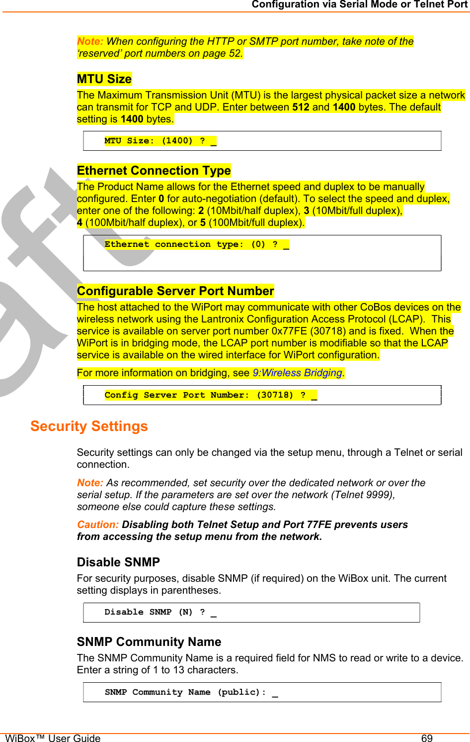
![Quick Start WiBox™ User Guide 22 The Server (0) settings The WLAN (4) settings Current settings display in parentheses. Note: Due to regulations, the country-specific setting has been removed from the setup menu and Web-Manager. We provide a separate utility for changing the Country/Zone setting. The utility is called SetZone and is included in the WiBox package. It is also available for download from the Lantronix web site. The syntax is SetZone <IP address> [<zone abbreviation>] Leaving the zone blank causes the utility to report the current setting only. Following are valid zone abbreviations. These settings are consistent with IEEE802.11b/G zones: US=United States and CanadaFR=France JP=Japan OT=Others, such as Europe (excluding France), Asia, Africa, and Australia 6. To configure the Server settings, select 0 from the Change Setup menu and edit the following fields: a) IP Address: The IP address must be set to a unique value in the network. Enter each octet and press Enter between each section inputted. IP Address: IP Address : ( 0) ( 0) ( 0) ( 0) _ b) Set Gateway IP Address: The gateway address should be the IP address of the router connected to the same LAN segment as the WiBox unit. Set Gateway IP Address (N) ? Y Gateway IP addr ( 0) ( 0) ( 0) ( 0)_ c) Netmask: A netmask defines the number of bits taken from the IP address that are assigned for the host part. Netmask: Number of Bits for Host Part (0=default)(0)_ d) Change Telnet Configuration Password: Change the Telnet configuration password to prevent unauthorized access to the Change Setup menu and Web-Manager. Change telnet config password (N) ? _ e) Change DHCP Device Name: Change the DHCP name if the network is DHCP-enabled. Change DHCP device name (not set) ? (N) N Enter new DHCP device name : 7. To modify WLAN settings, select 4 WLAN from the Change Setup menu and edit the following fields: a) Enable WLAN: Enable the Ethernet or the Wireless interface. When enabling WLAN, the Ethernet interface is disabled. Enable WLAN (Y) ? _ b) Topology: Select Infrastructure (ESS) mode or Adhoc (IBSS) mode. Infrastructure mode communicates with Access Points. Adhoc mode communicates only with other clients.](https://usermanual.wiki/lantronix/WIPORTG.USERS-GUIDE/User-Guide-672039-Page-22.png)
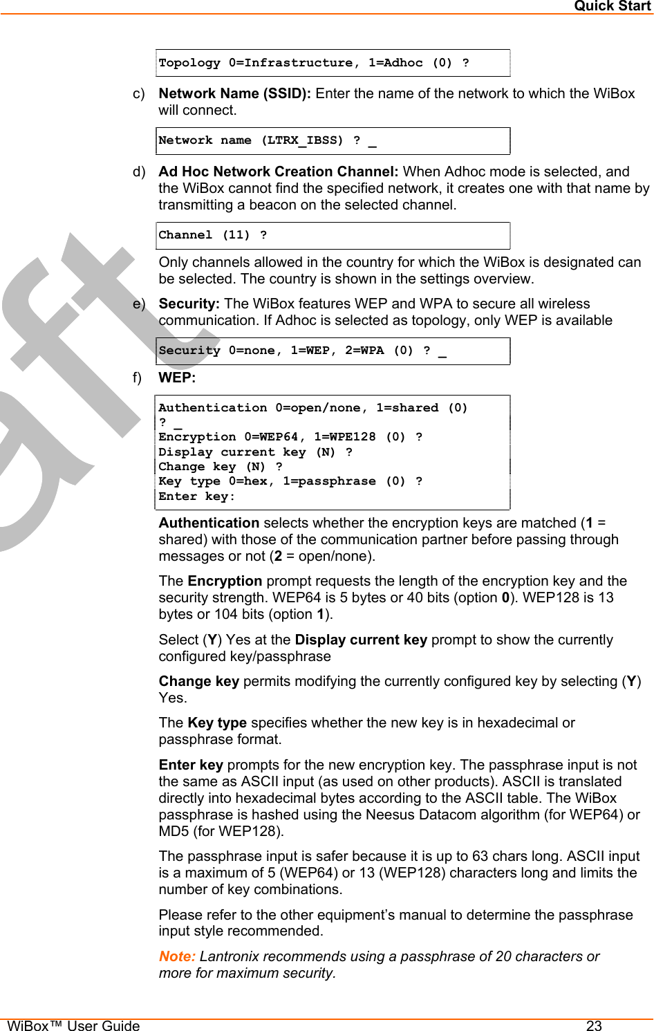

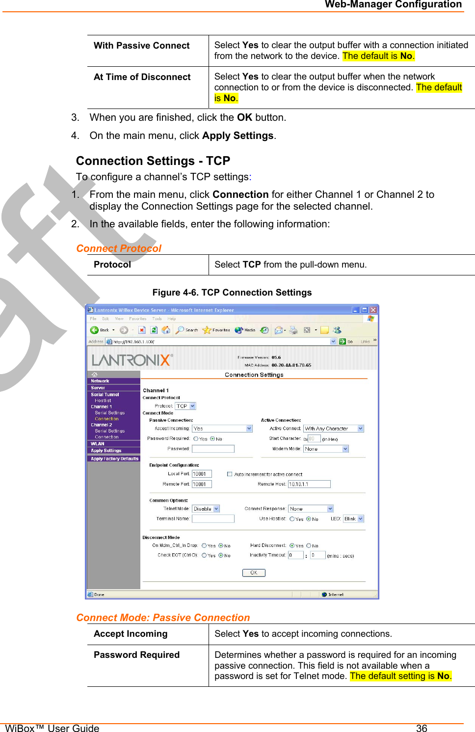
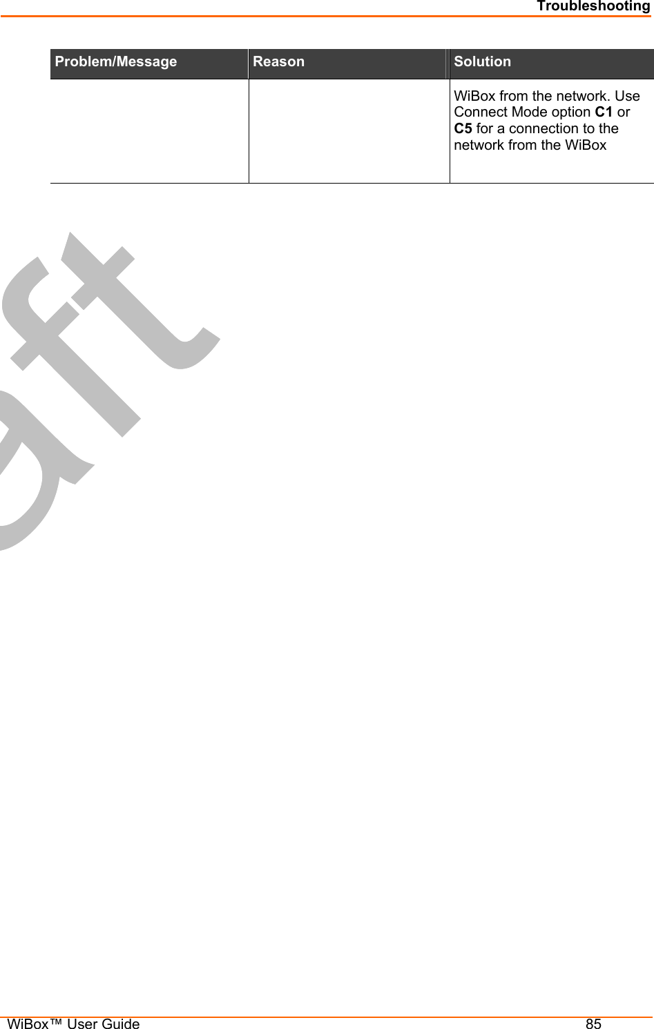
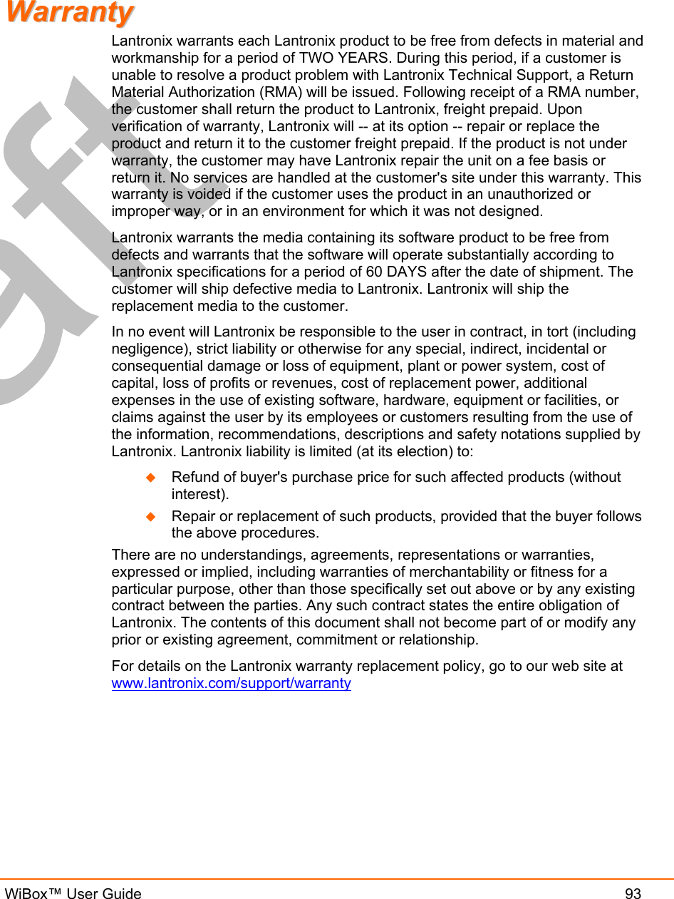
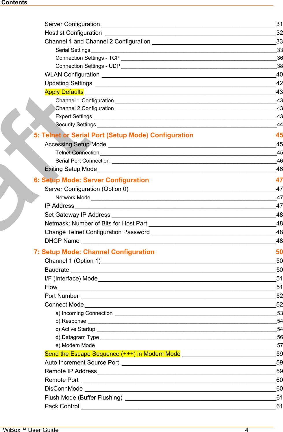
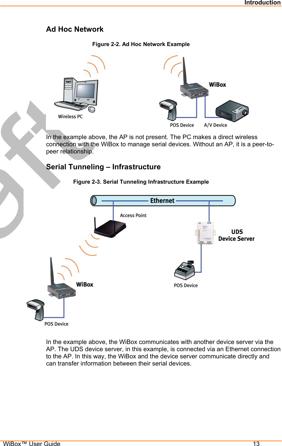
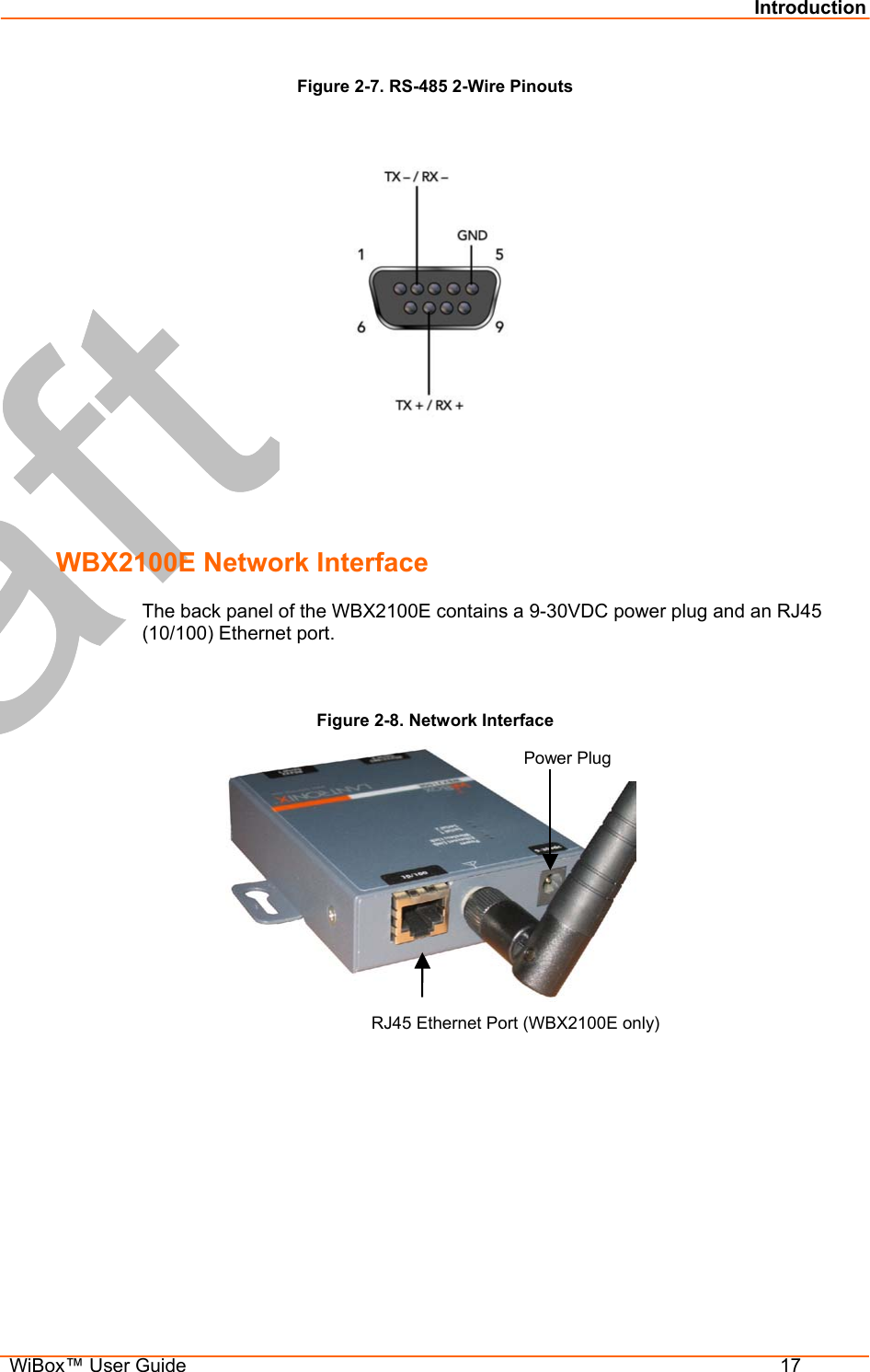
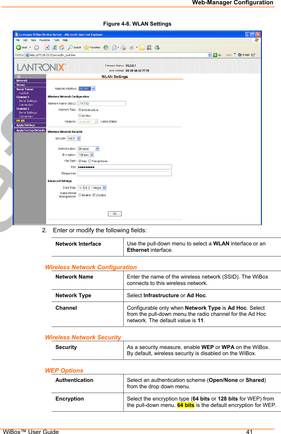
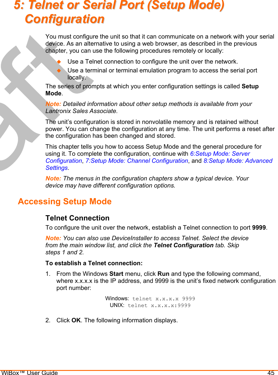
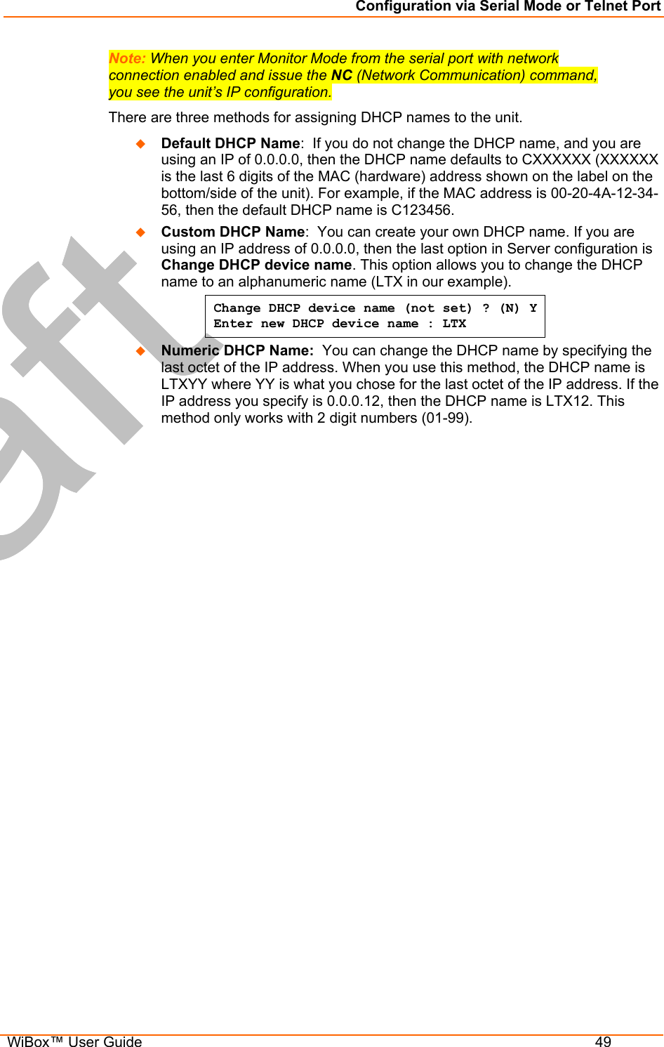
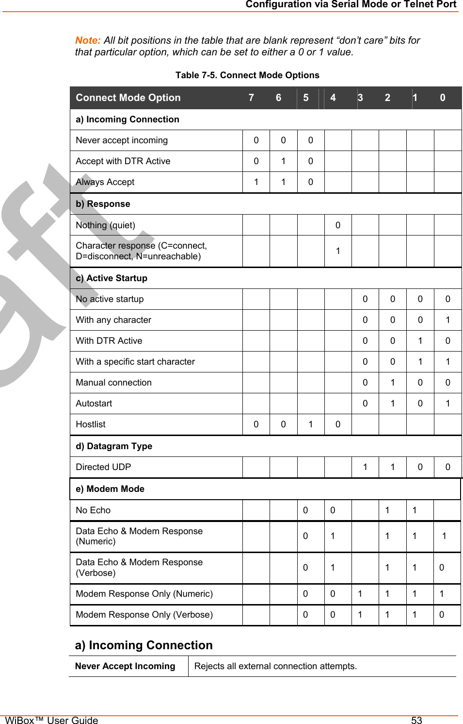
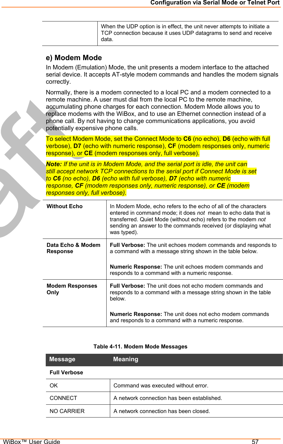
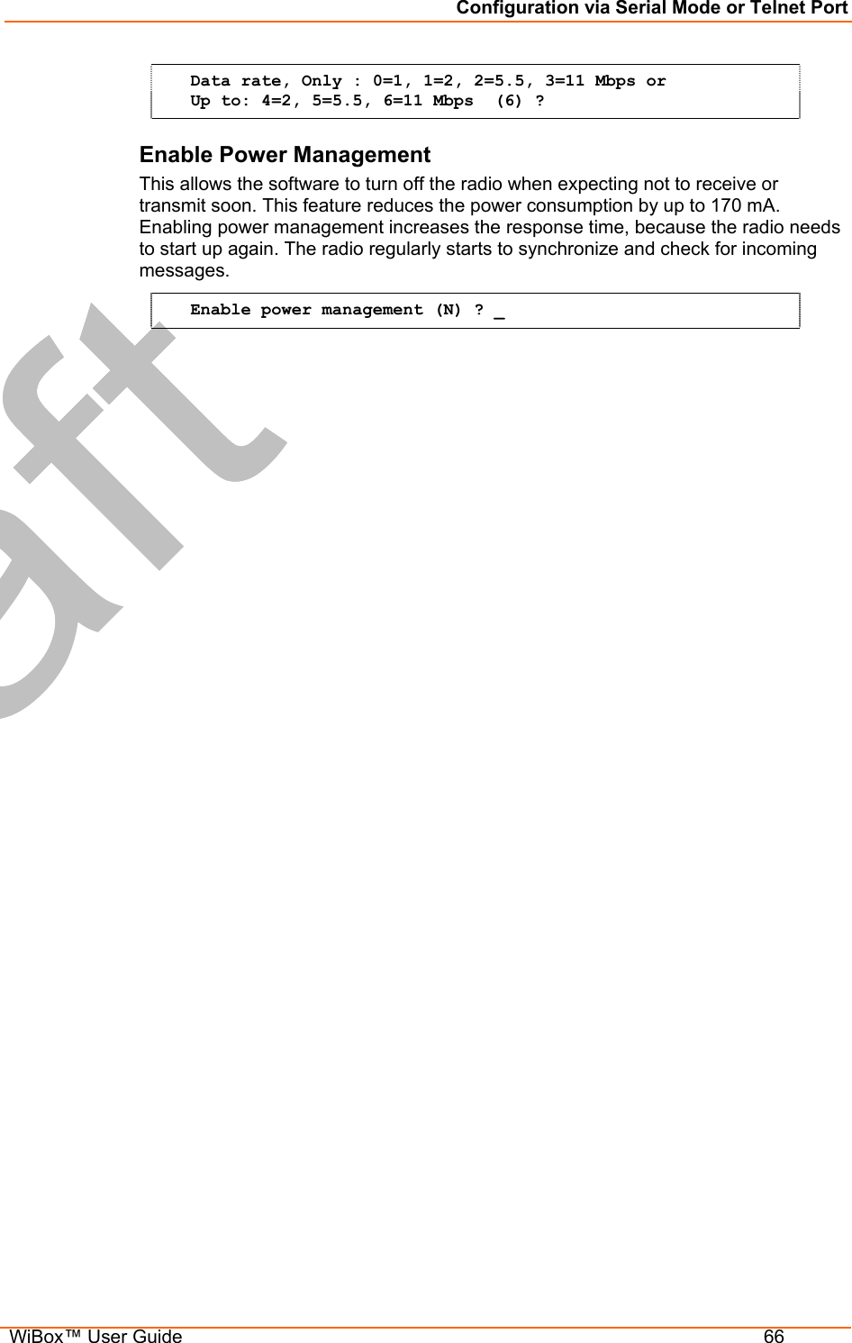
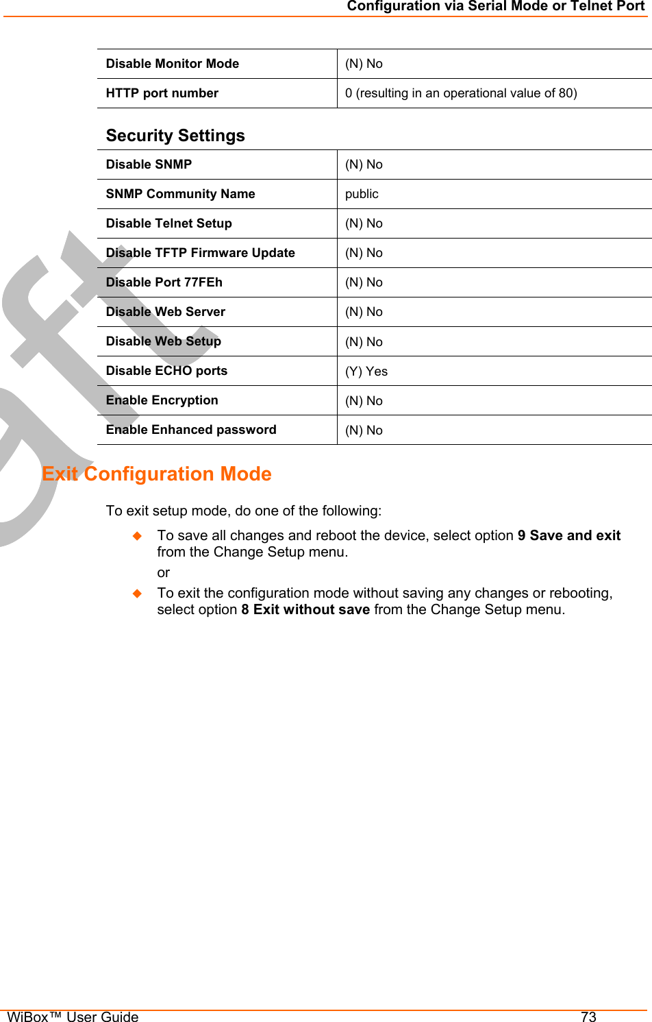
![Web-Manager Configuration WiBox™ User Guide 40 WLAN Configuration Without adequate protection, a wireless LAN is susceptible to access by unauthorized users. The WiBox WLAN Settings menu permits the following actions: Configuration of the wireless network profile available for activation. Configuration of the wireless network security settings. Configuration of advanced settings such as radio power management. Note: Due to regulations, the country-specific setting has been removed from the setup menu and Web-Manager. We do, however, provide a separate utility for changing the Country/Zone setting. The utility is called SetZone and is included in the WiBox package. It is also available for download from the Lantronix web site. The syntax is SetZone <IP address> [<zone abbreviation>] Leaving the zone blank causes the utility to report the current setting only. Following are valid zone abbreviations. These settings are consistent with IEEE802.11b/G zones: US=United States and CanadaFR=France JP=Japan OT=Others, such as Europe (excluding France), Asia, Africa, and Australia To configure the WiBox’s WLAN settings: 1. Select WLAN from the main menu to open the WLAN Settings window.](https://usermanual.wiki/lantronix/WIPORTG.USERS-GUIDE/User-Guide-672039-Page-40.png)
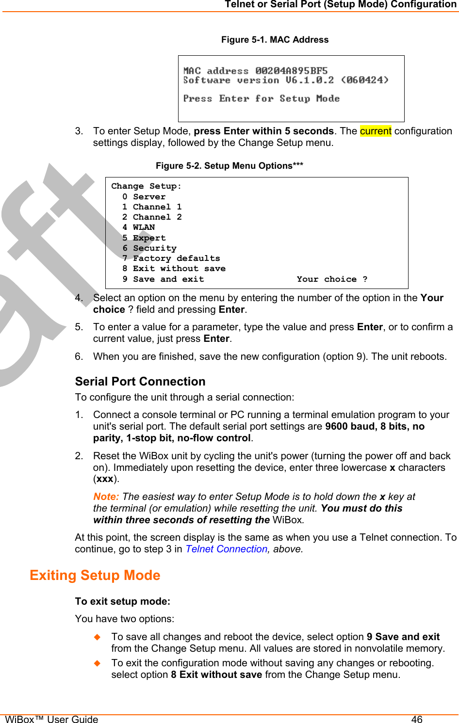
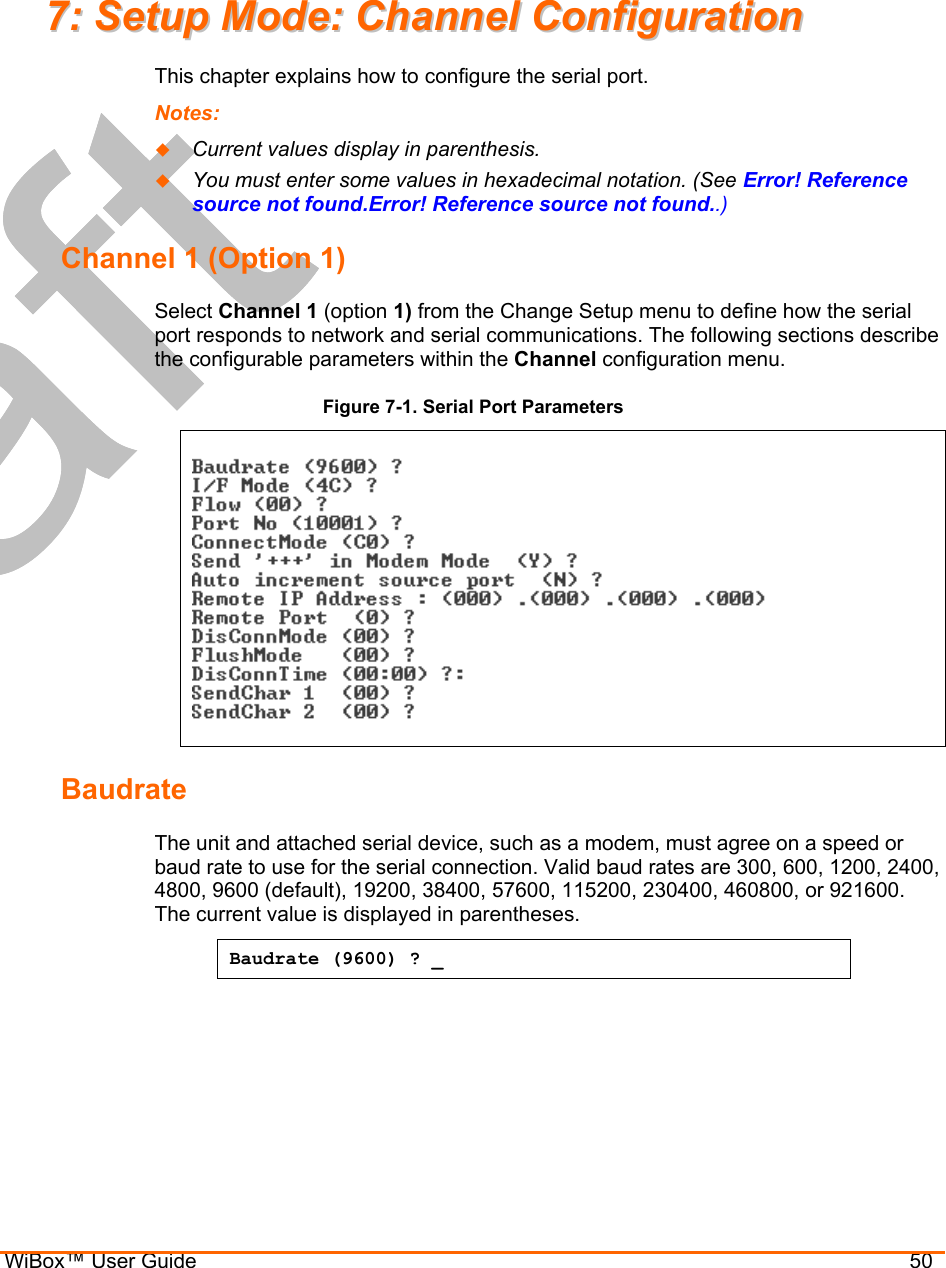
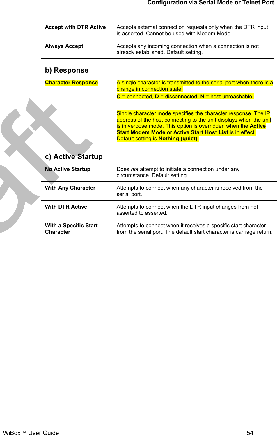
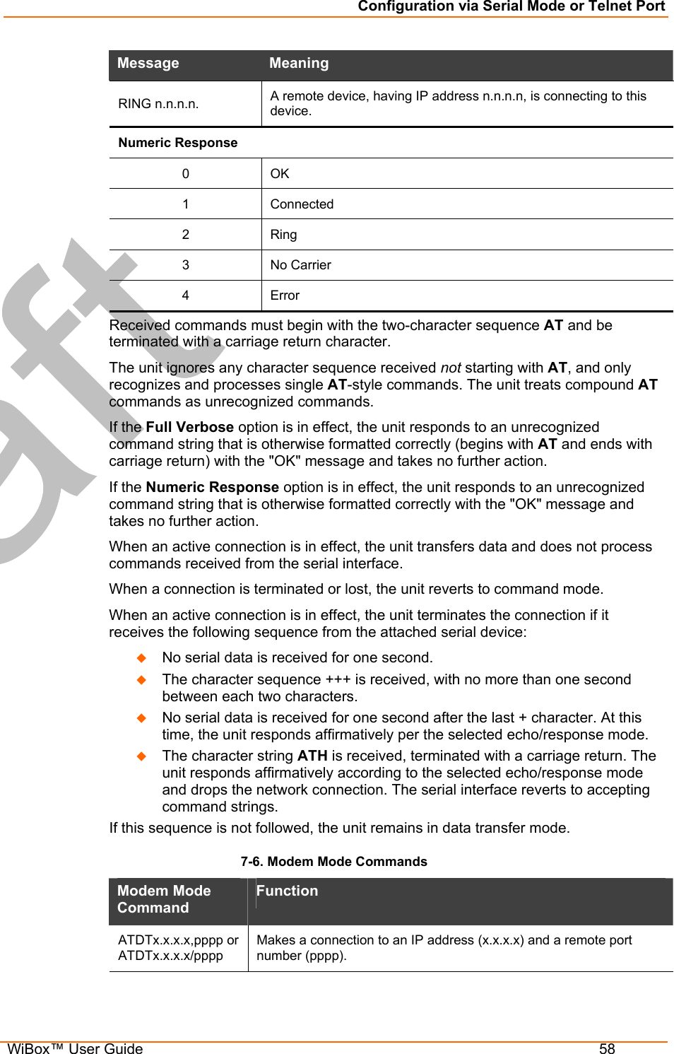
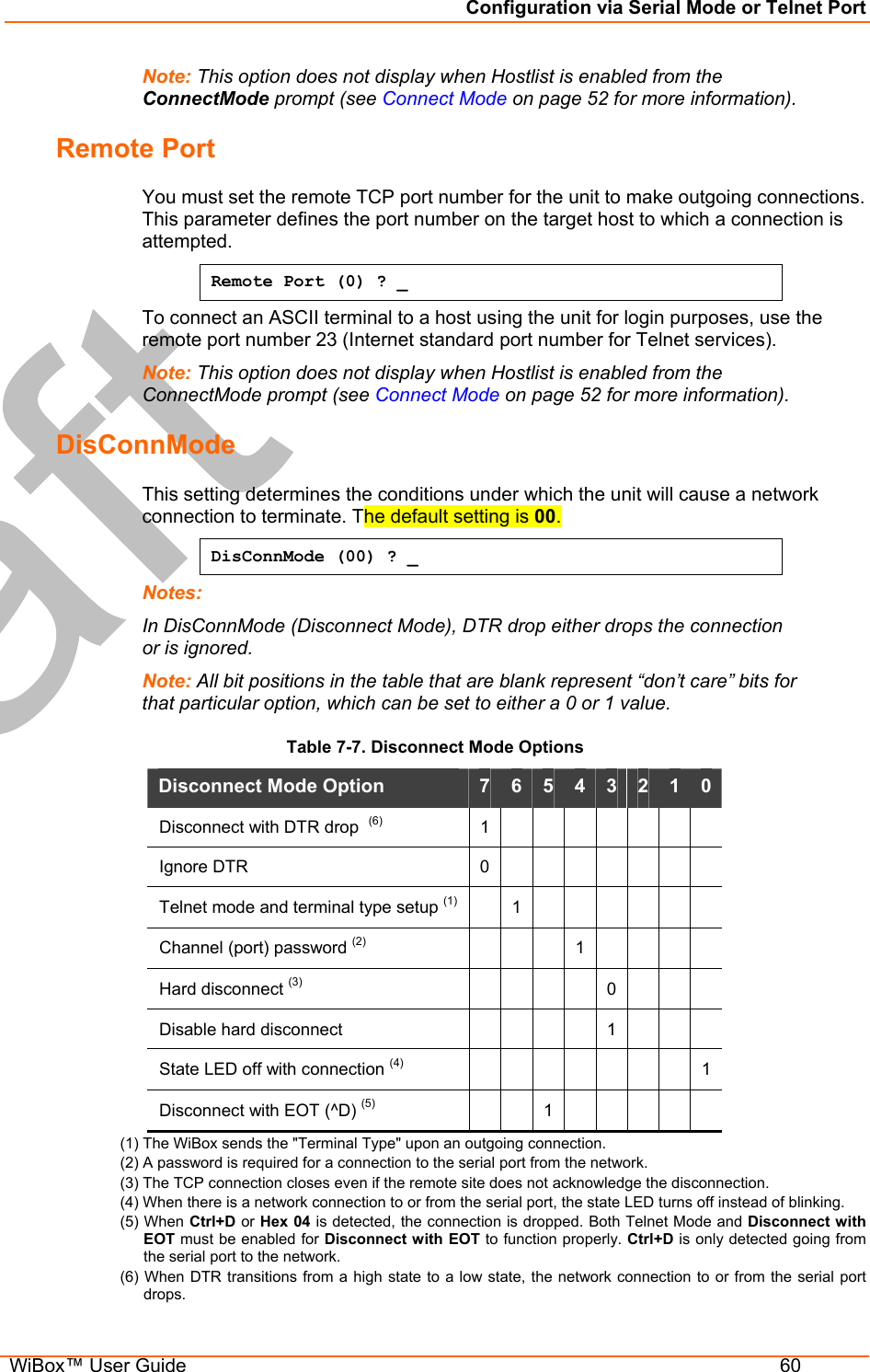
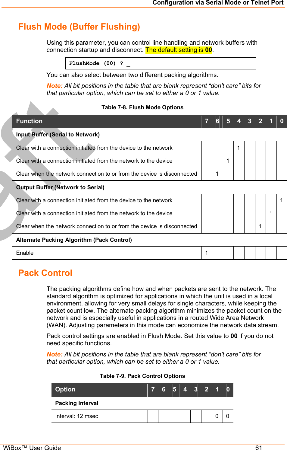
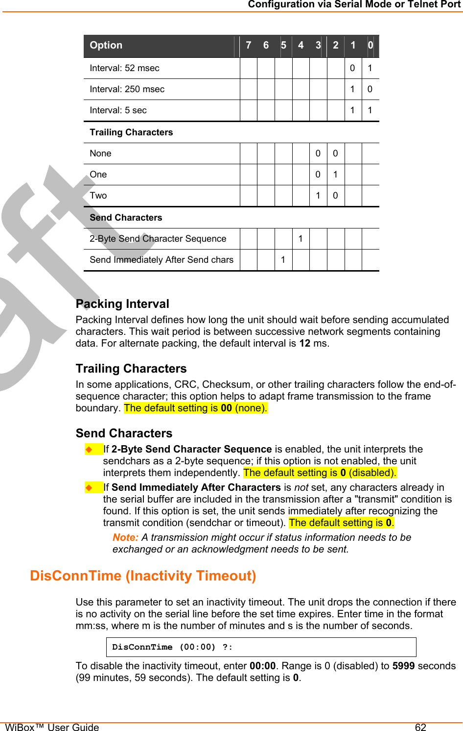
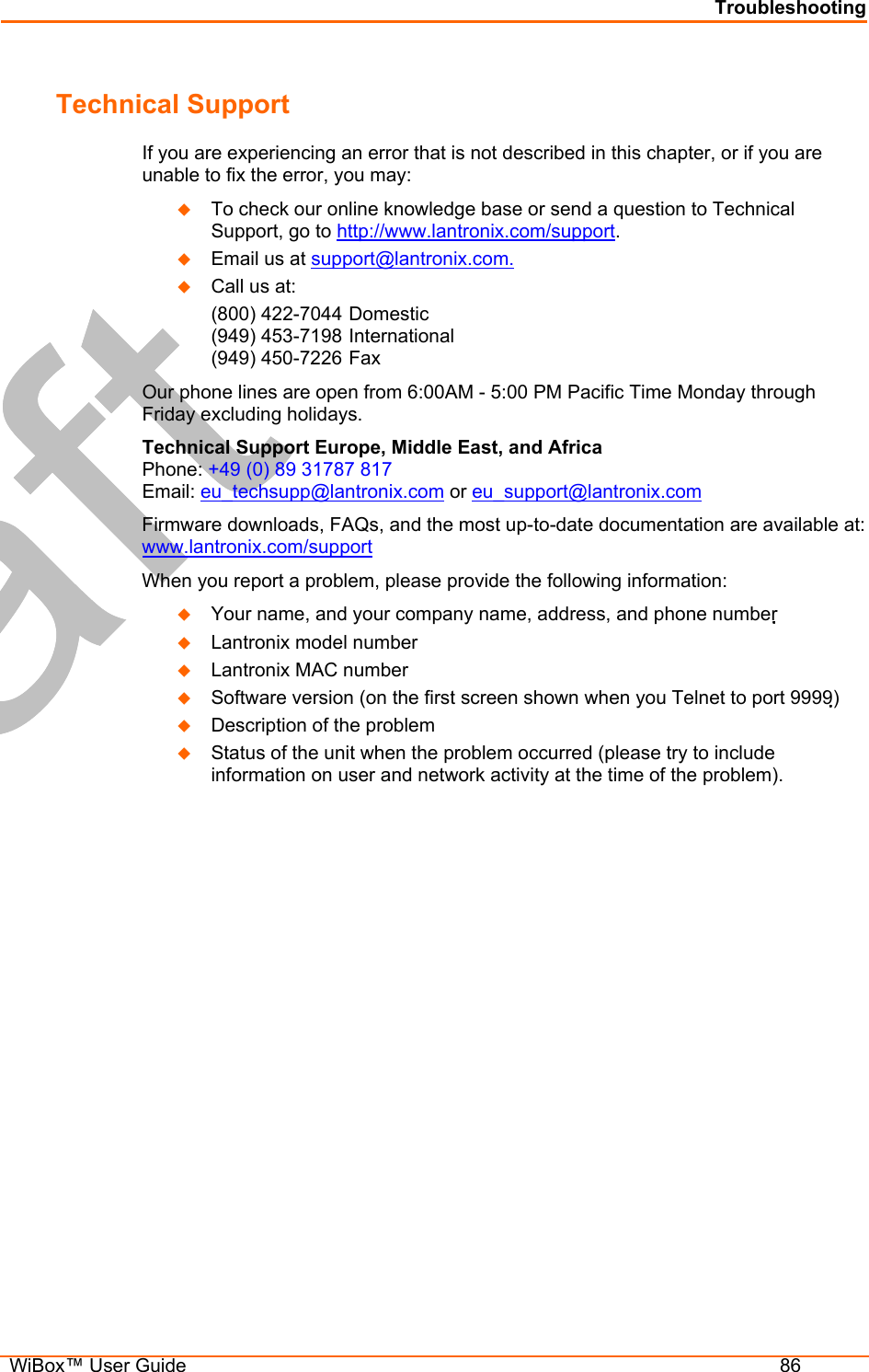
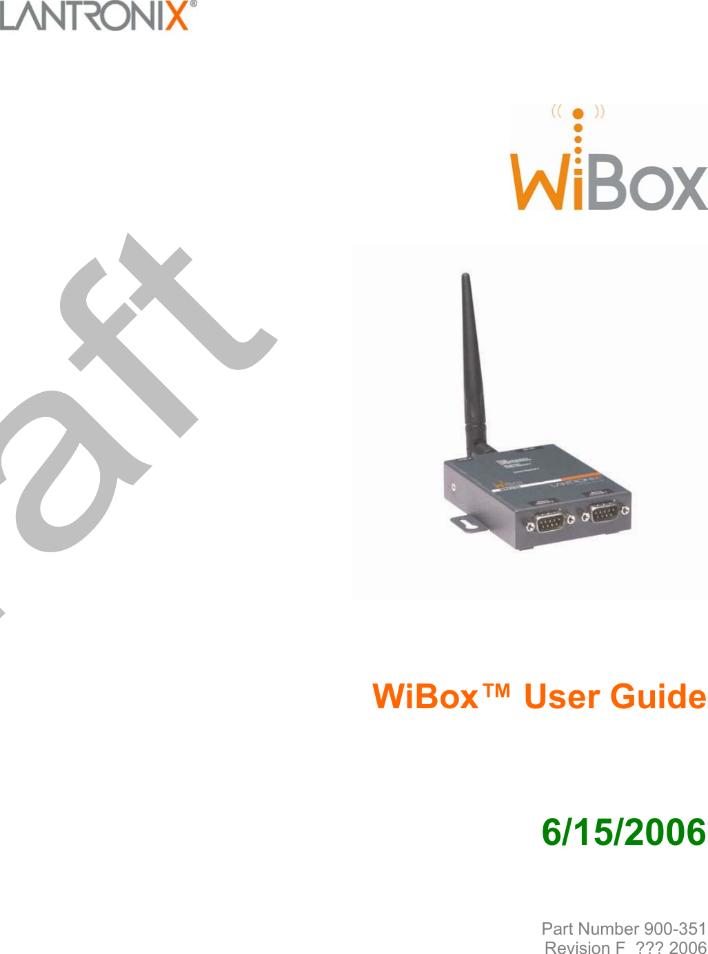
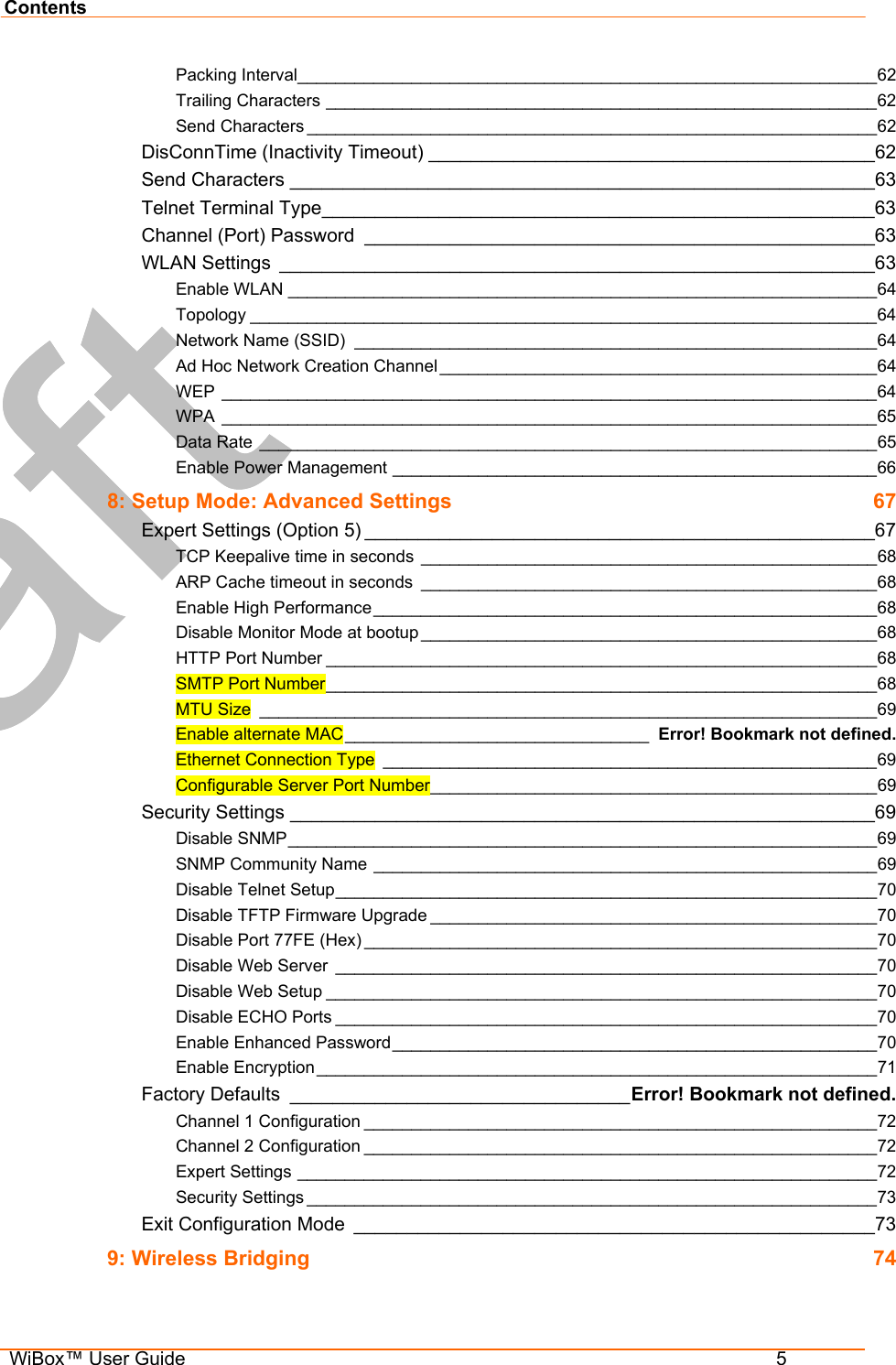
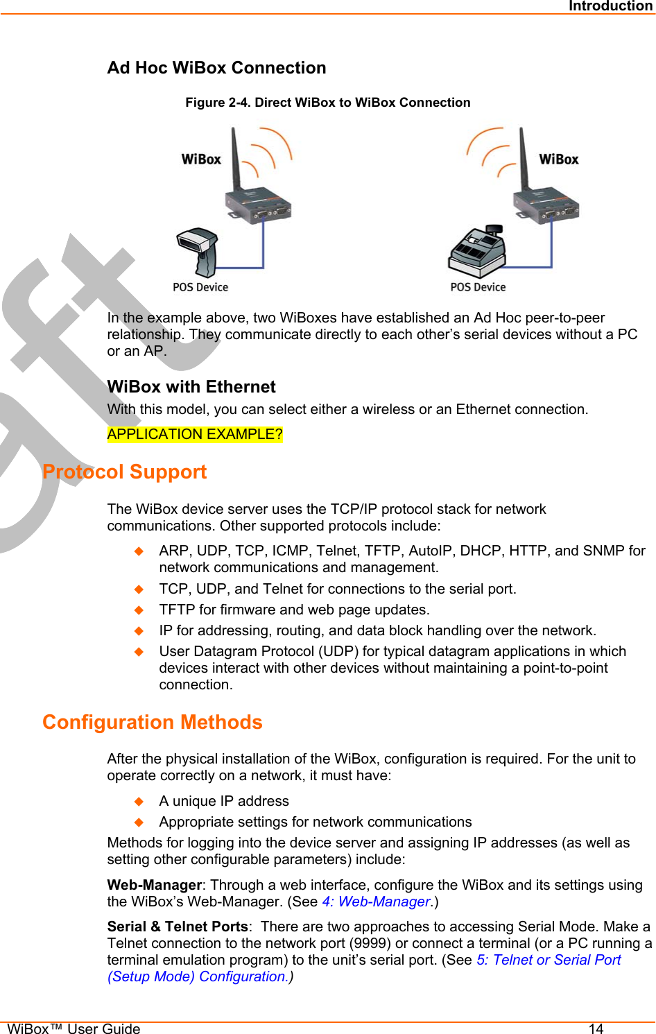
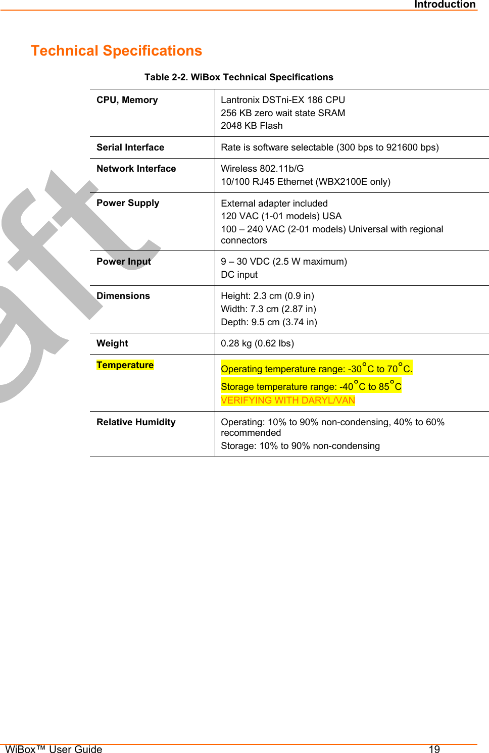
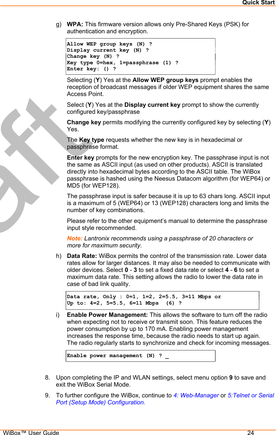
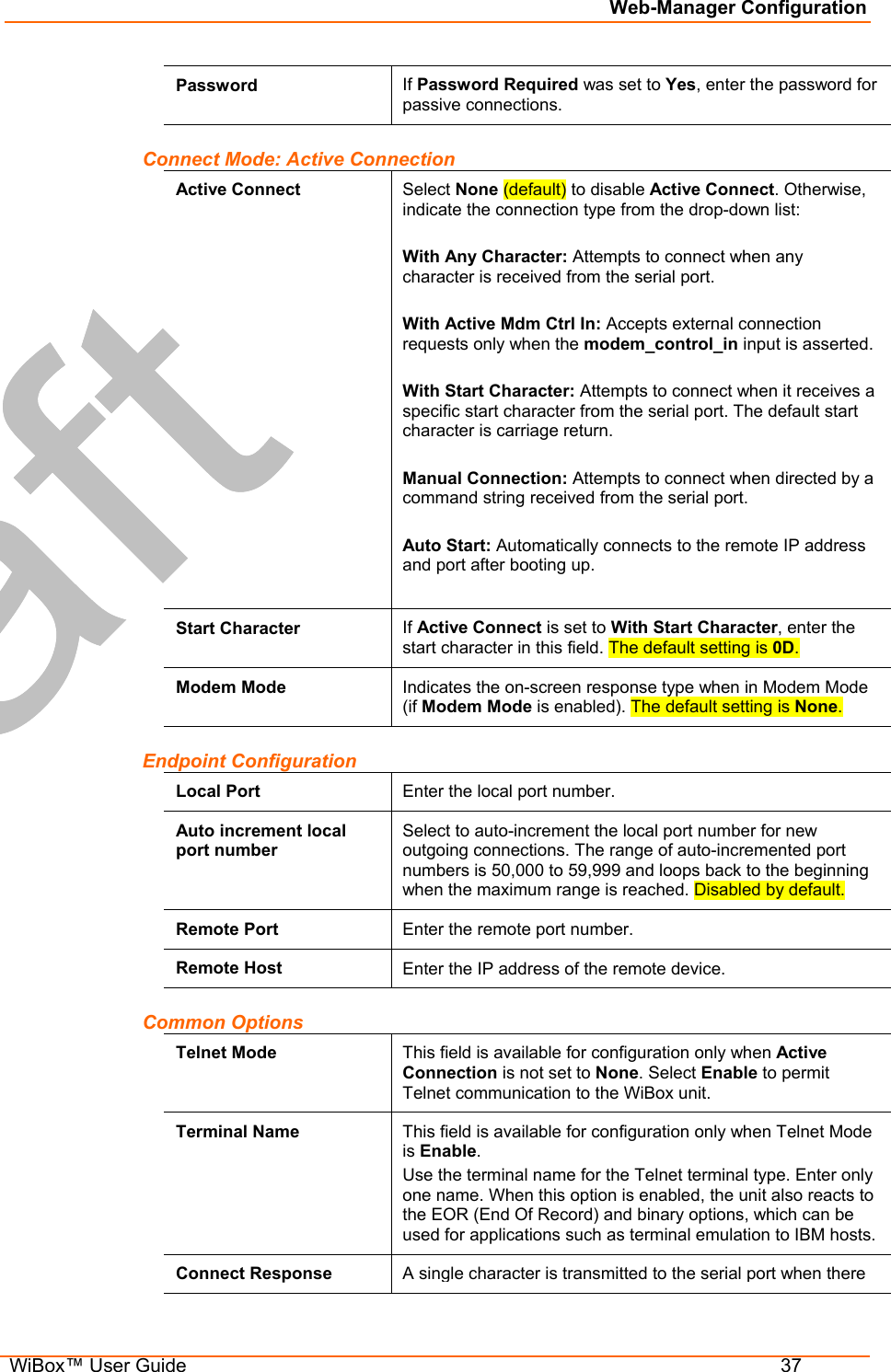
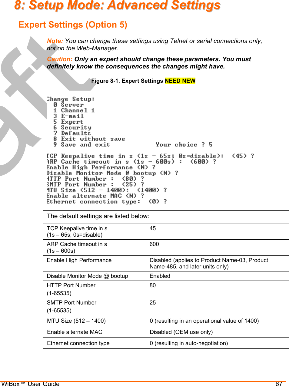
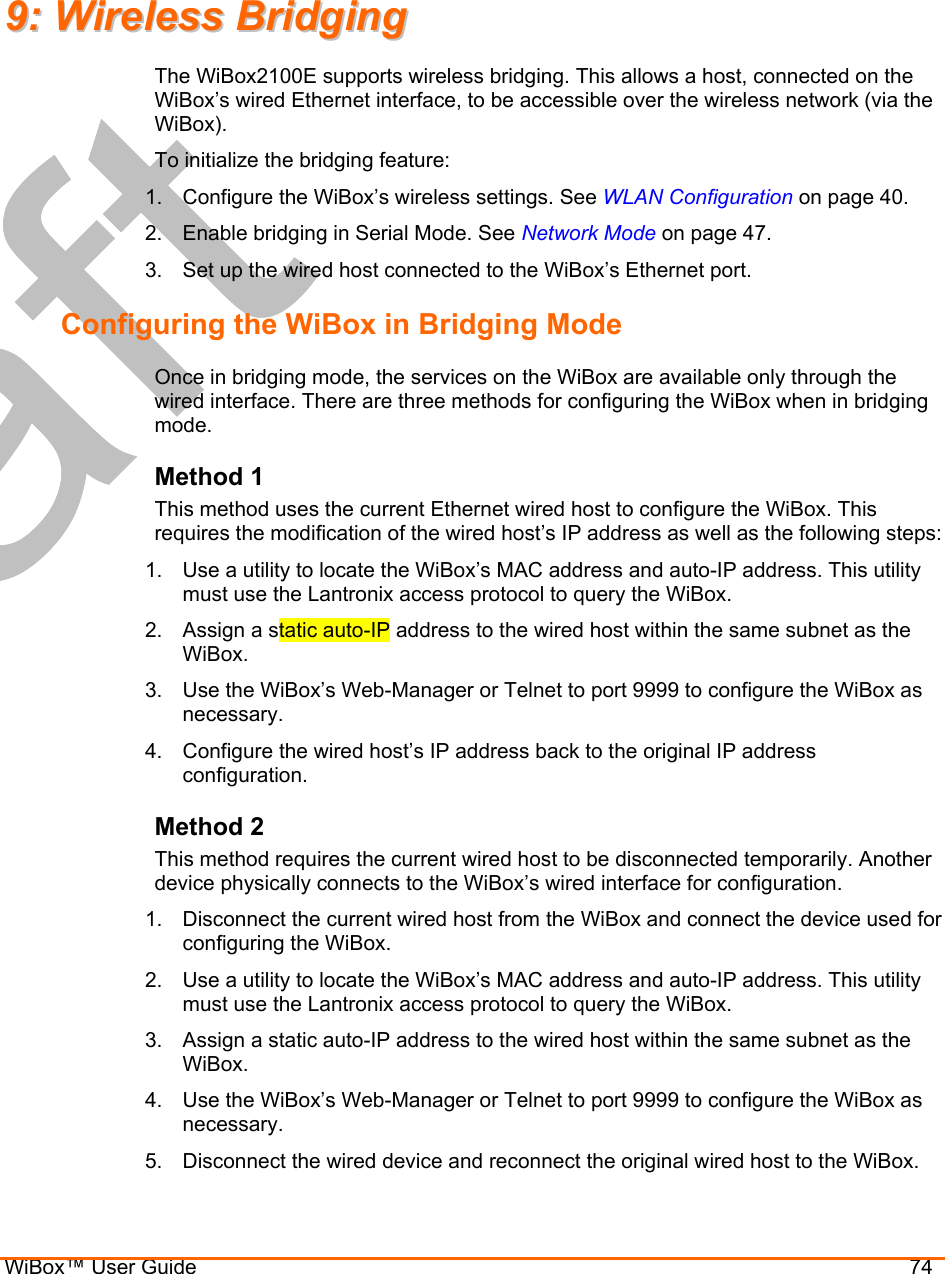
![Configuration via Serial Mode or Telnet Port WiBox™ User Guide 63 Send Characters Enter up to two characters in hexadecimal representation in sendchar. SendChar 1 (00) ? _ SendChar 2 (00) ? _ If the unit receives a character on the serial line that matches one of these characters, it sends the character immediately, along with any awaiting characters, to the TCP connection. This action minimizes the response time for specific protocol characters on the serial line (for example, ETX, EOT). Setting the first sendchar to 00 disables the recognition of the characters. Alternatively, the unit can interpret two characters as a sequence (see Pack Control on page 61). The default setting is 00. Telnet Terminal Type This parameter displays only if you enabled the terminal type option in Disconnect Mode. With this option enabled, you can use the terminal name for the Telnet terminal type. Enter only one name. With terminal type option enabled, the unit also reacts to the EOR (end of record) and binary options, useful for applications like terminal emulation to IBM hosts. Channel (Port) Password This parameter displays only if the channel (port) password option is enabled in Disconnect Mode. With this option enabled, you can set a password on the serial port. The default setting is all 0s. WLAN Settings Without adequate protection, a wireless LAN is susceptible to access by unauthorized users. WiBox features the WPA security standard, based on IEEE802.11i and IEEE802.1X. WEP is provided for backwards compatibility and interaction with older devices. Without adequate protection, a wireless LAN is susceptible to access by unauthorized users. The WiBox WLAN Settings menu permits the following actions: Configuration of the wireless network profile available for activation. Configuration of the wireless network security settings. Configuration of advanced settings such as radio power management. NOT IN COBOS MASTER: Note: Due to regulations, the country-specific setting has been removed from the setup menu and Web-Manager. We do, however, provide a separate utility for changing the Country/Zone setting. The utility is called SetZone and is included in the package. It is also available for download from the Lantronix web site. The syntax is: SetZone <IP address> [<zone abbreviation>] Leaving the zone blank causes the utility to report the current setting only. Following are valid zone abbreviations. These settings are consistent with IEEE802.11b/G zones:](https://usermanual.wiki/lantronix/WIPORTG.USERS-GUIDE/User-Guide-672039-Page-63.png)
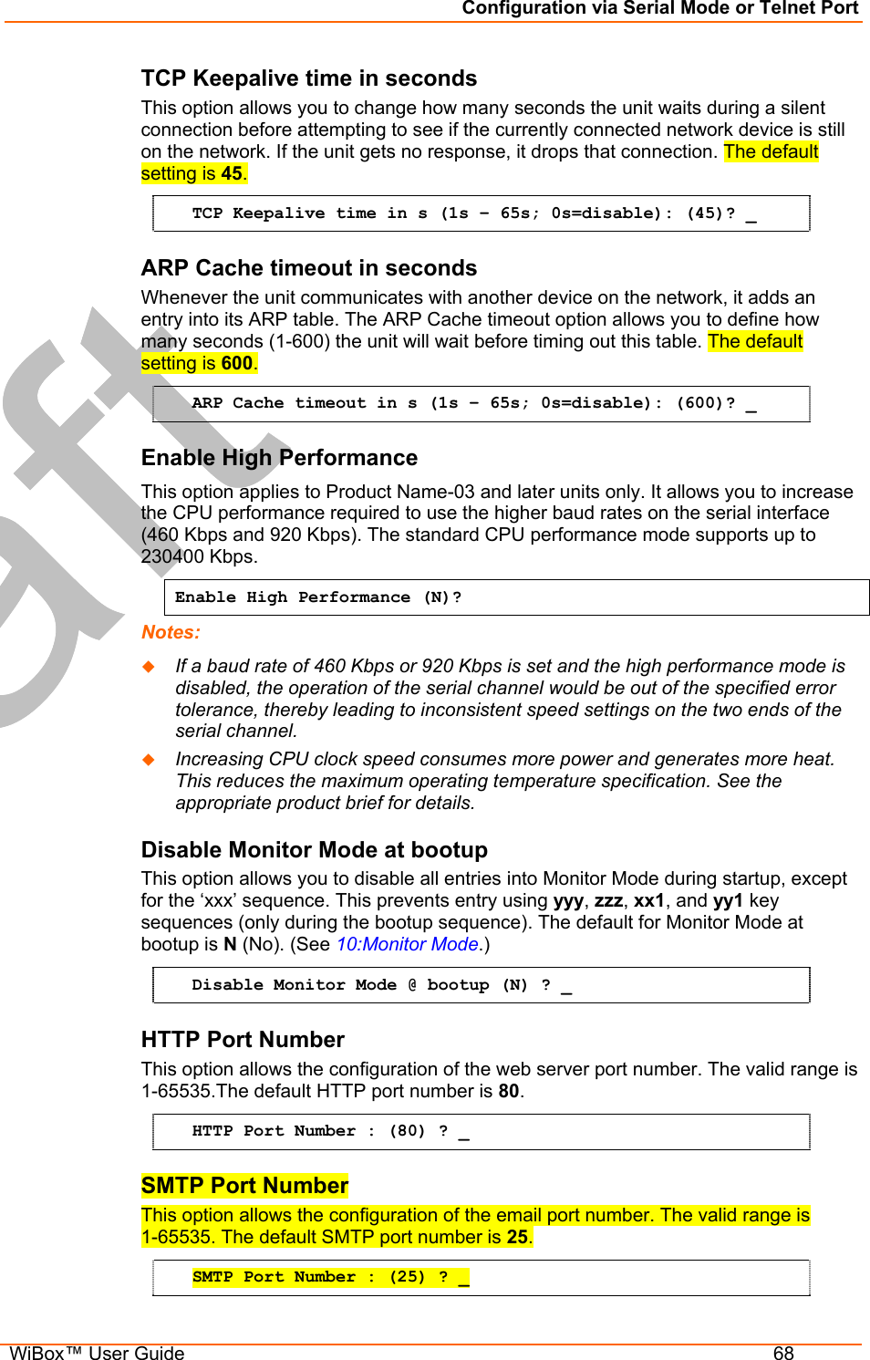


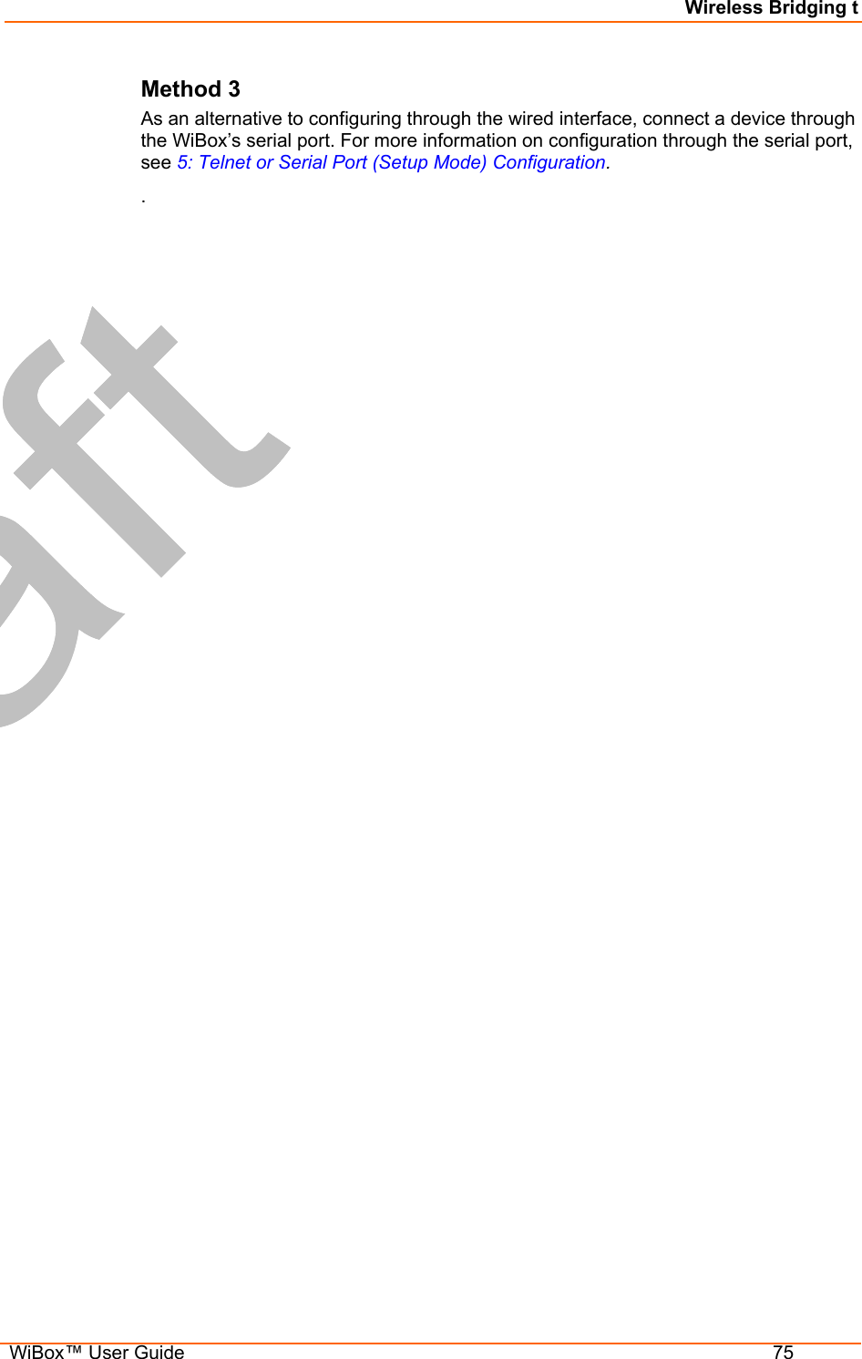

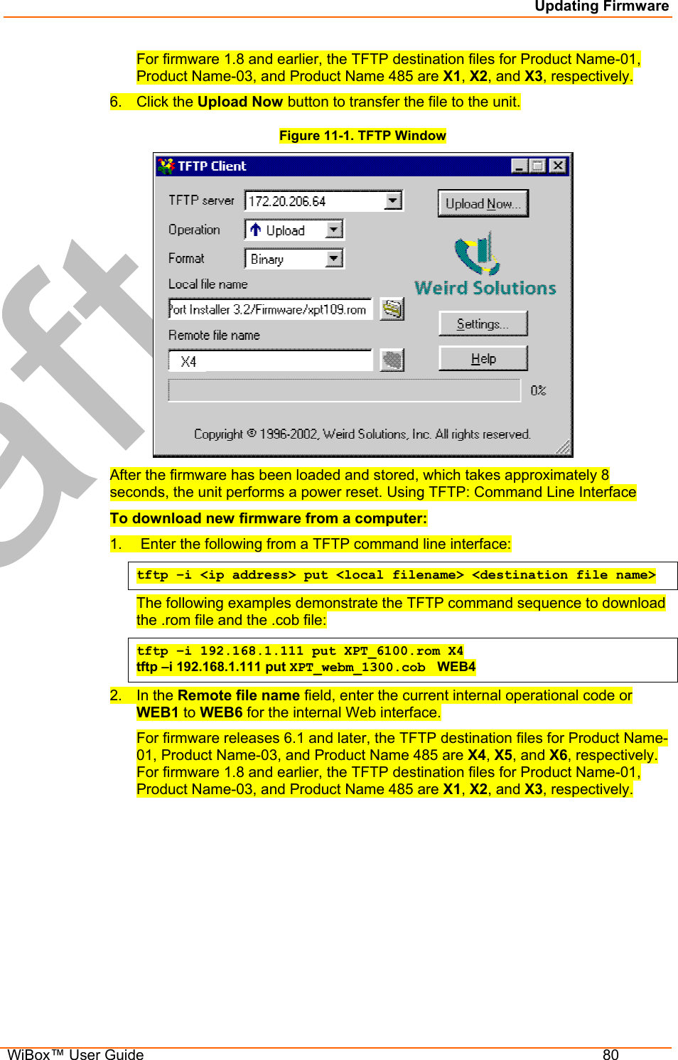
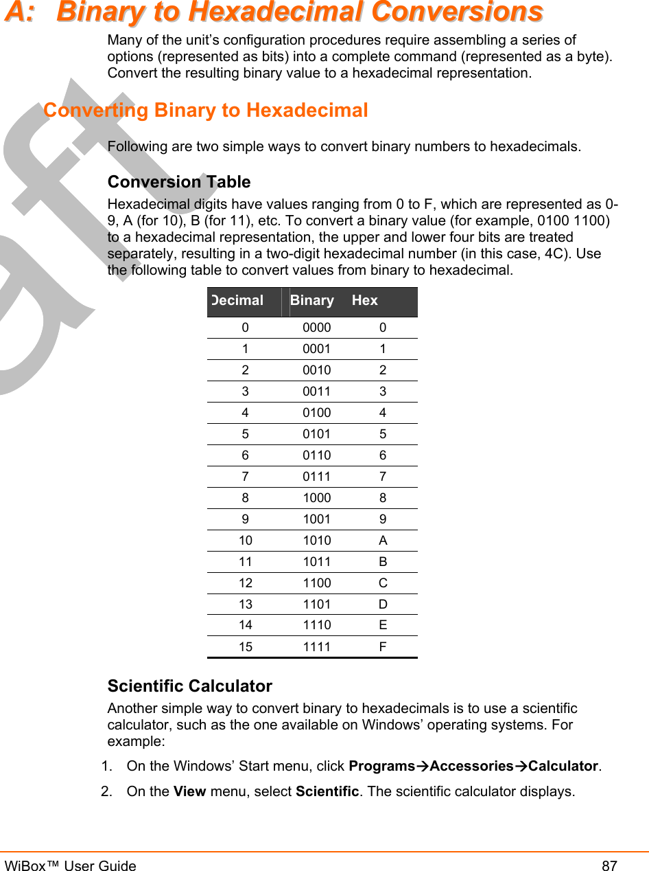
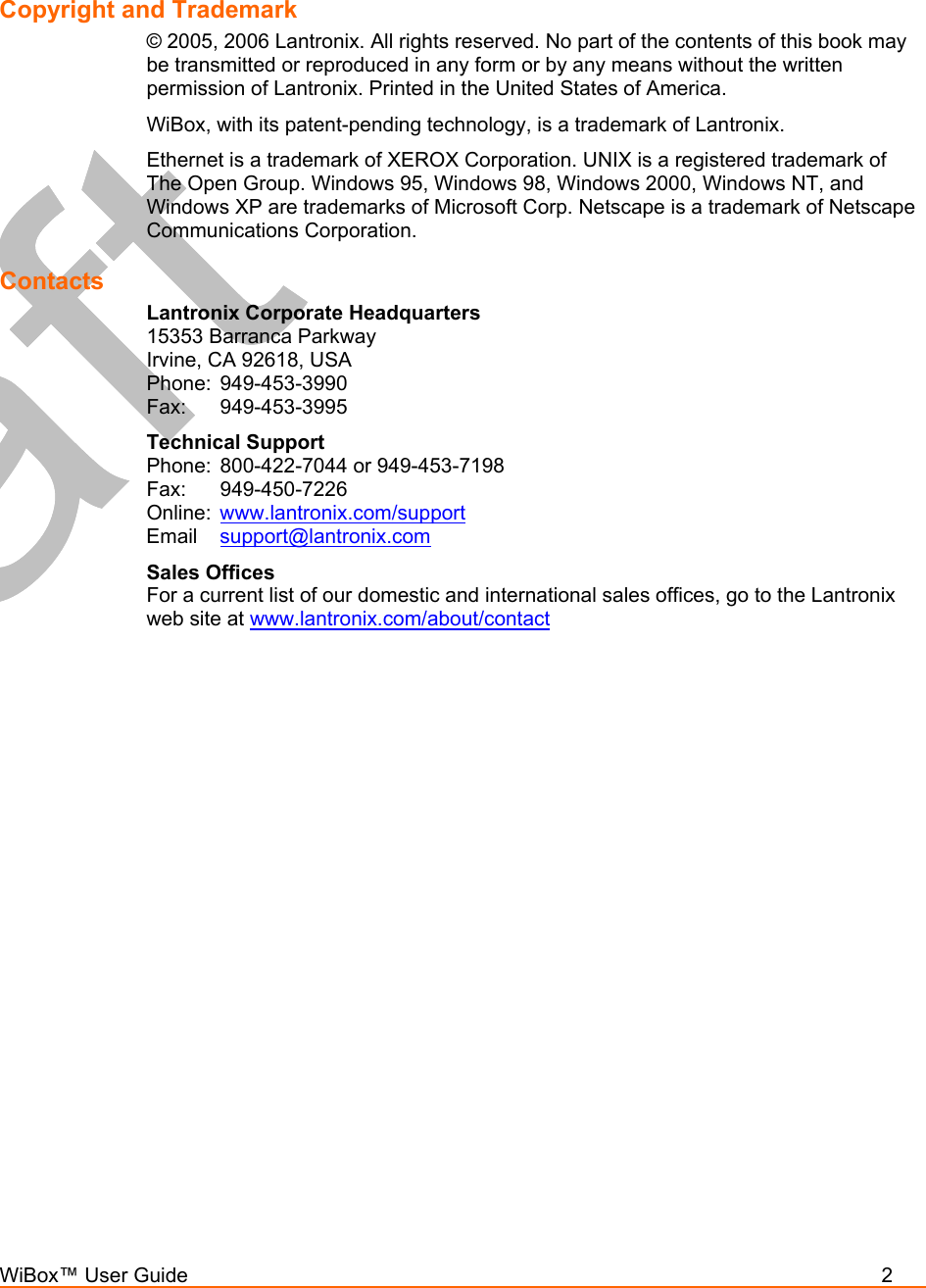
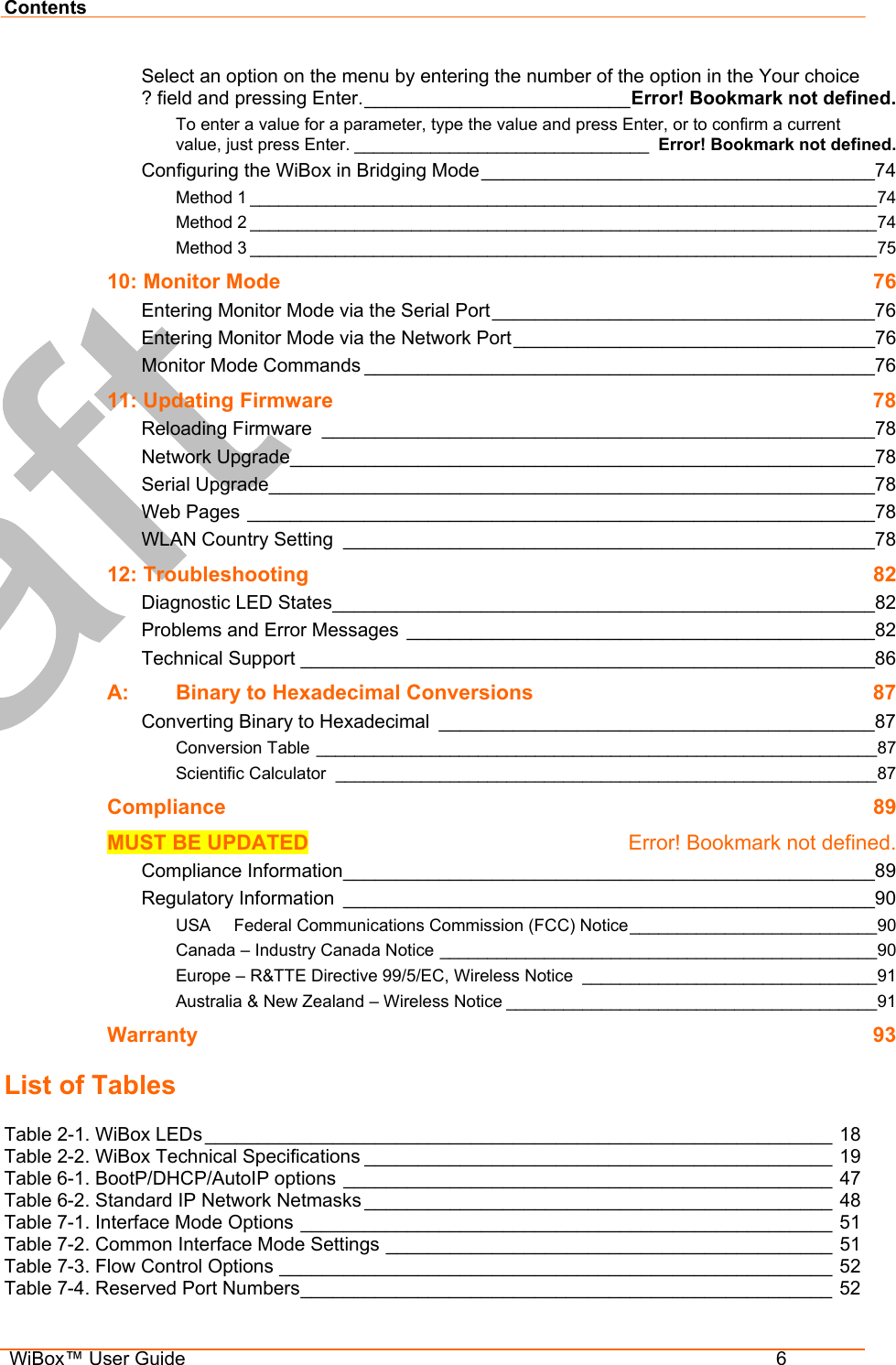
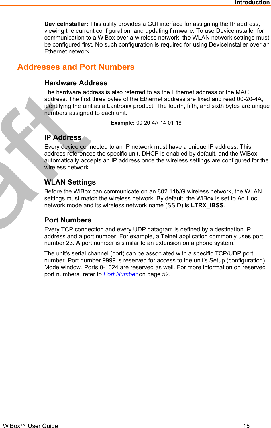
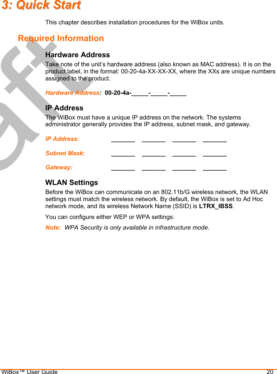
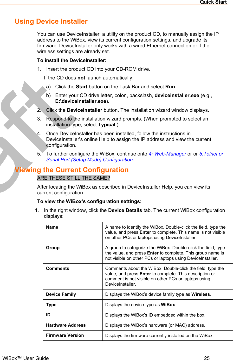
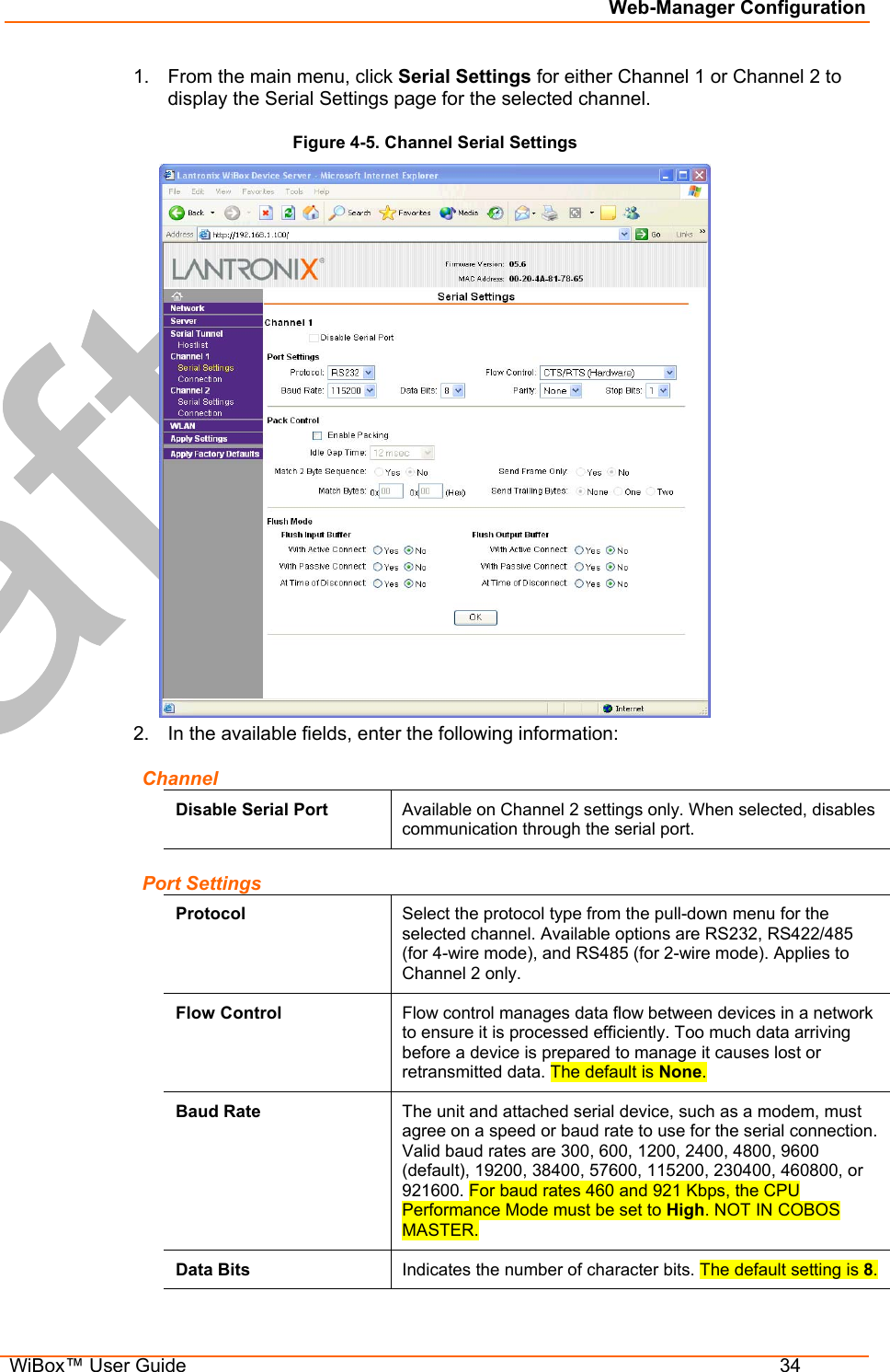
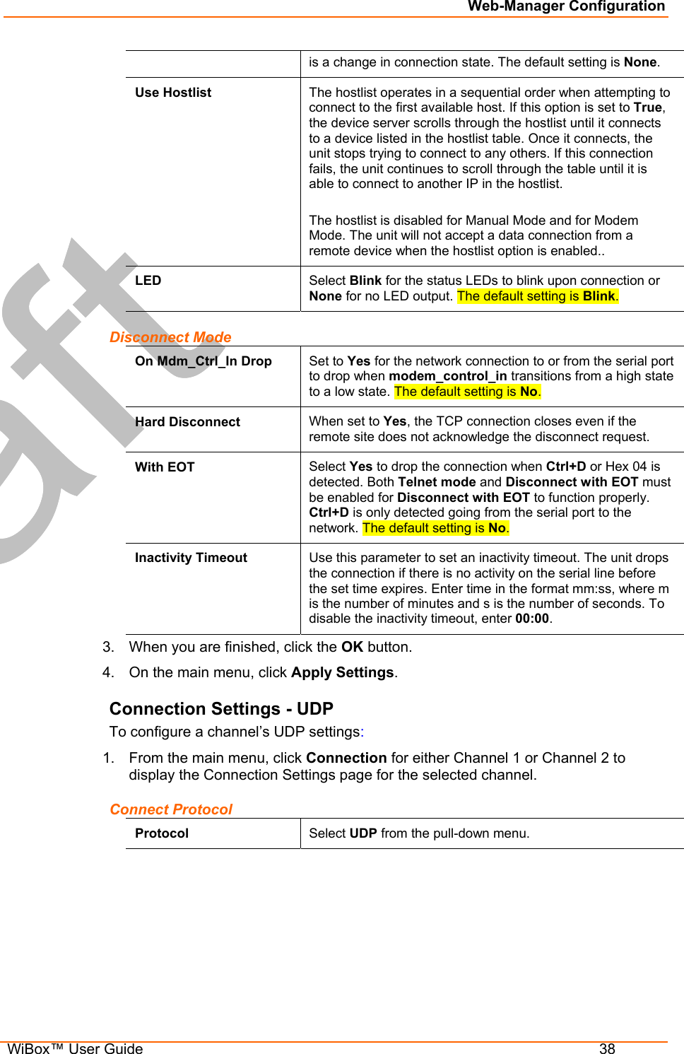
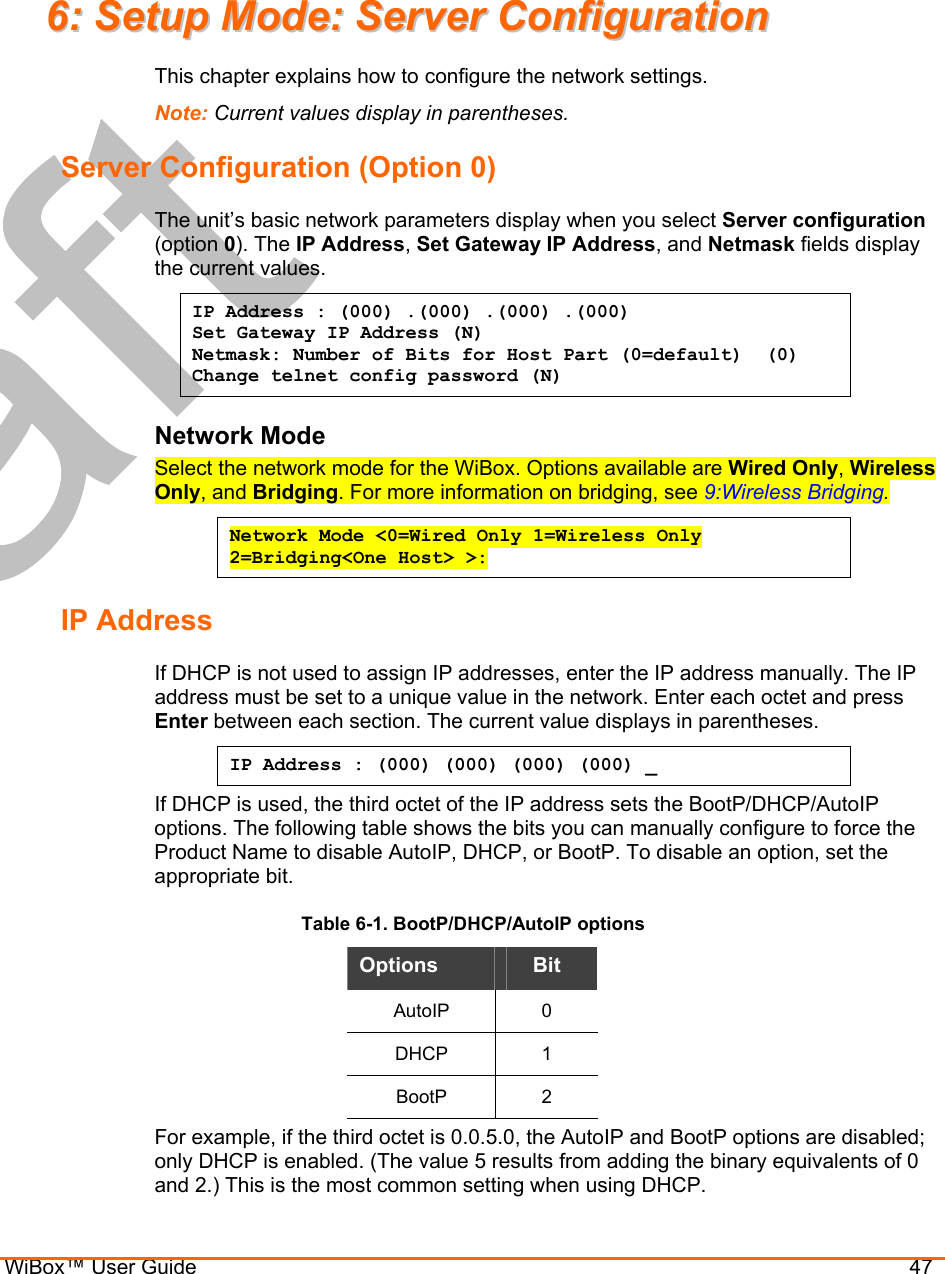
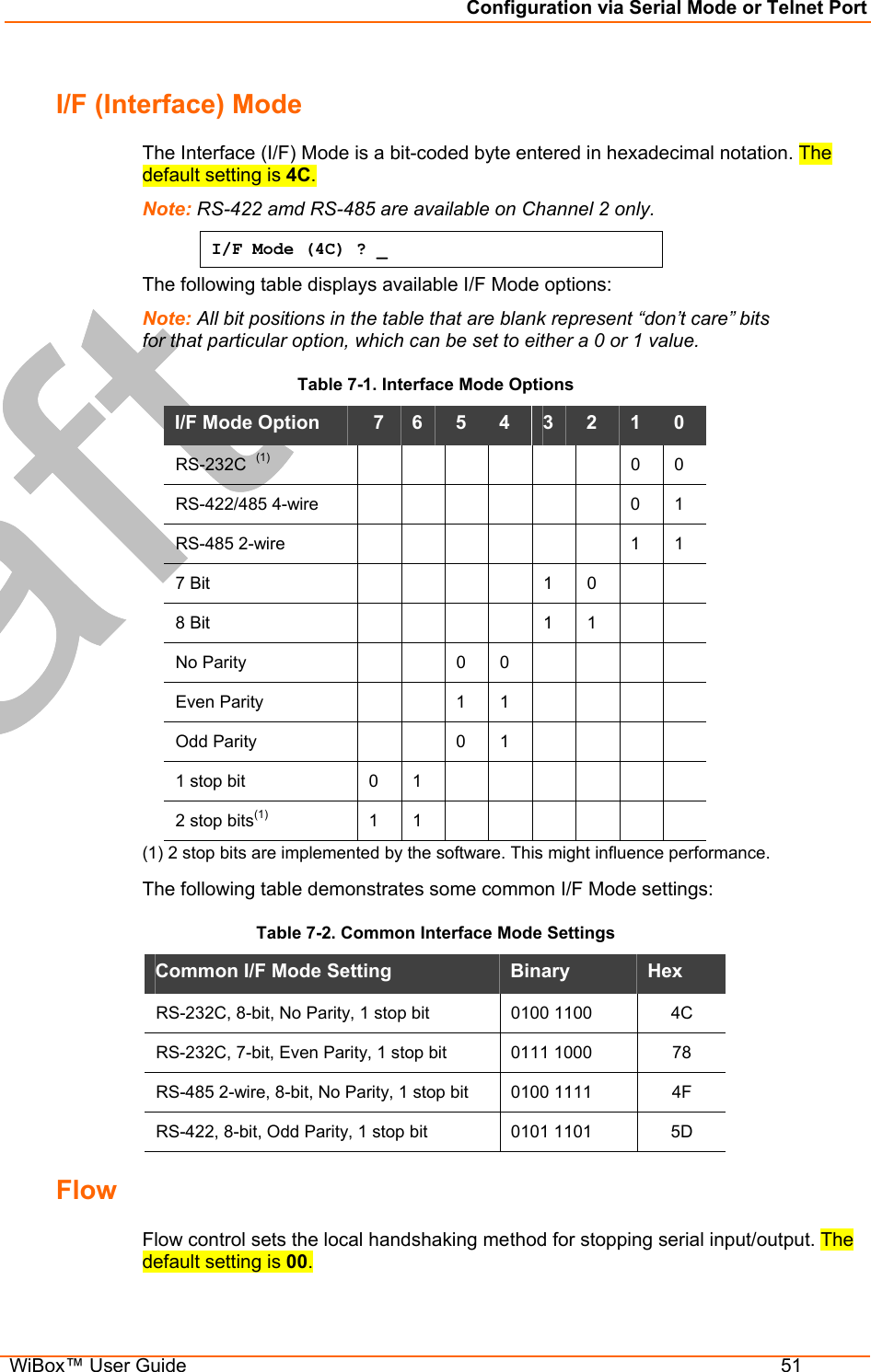
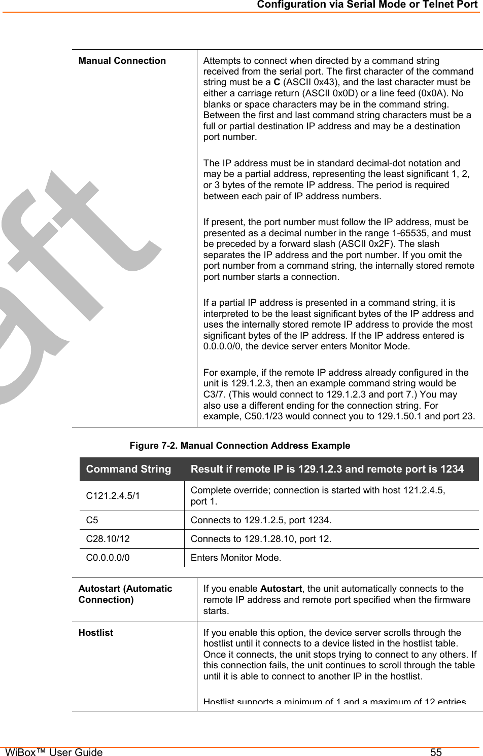
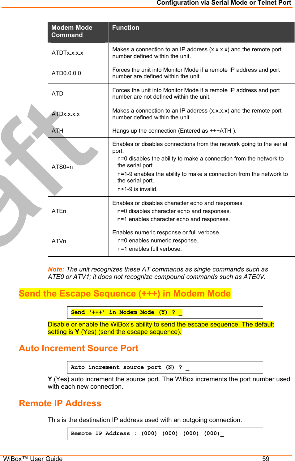
![Updating Firmware WiBox™ User Guide 79 The syntax is: SetZone <IP address> [<zone abbreviation>] Leaving the zone blank causes the utility to report the current setting only. Following are valid zone abbreviations. These settings are consistent with IEEE802.11b/G zones: US=United States and CanadaFR=France JP=Japan OT=Others, such as Europe (excluding France), Asia, Africa, and Australia THE FOLLOWING IS WHAT WE HAVE IN THE COBOS MASTER: Obtaining Firmware You can obtain the most up-to-date firmware and release notes for the unit from the Lantronix web site (www.lantronix.com) or by using anonymous FTP (ftp.lantronix.com). Reloading Firmware Note: For details on upgrading to version 6.1.0.0 from pre-6.1.0.0, see the Product Name Upgrade Notice on the Lantronix ftp site (ftp.lantronix.com). There are several ways to update the unit's internal operational code (*.ROM): using DeviceInstaller (the preferred way), using TFTP, or using the serial port. You can also update the unit's internal Web interface (*.COB) using TFTP or DeviceInstaller. Here are typical names for those files. Check the Lantronix web site for the latest versions and release notes. Table 11-2. Firmware Files ROM File COB XPT_6100.rom XPT_webm_1300.cob Please refer to the DeviceInstaller online Help for information about reloading firmware using DeviceInstaller. The other methods are discussed below. Using TFTP: Graphical User Interface To download new firmware from a computer: 1. Use a TFTP client to send a binary file to the unit (*.ROM to upgrade the unit's internal operational code and *.COB to upgrade its internal Web interface). Note: TFTP requires the .ROM (binary) version of the unit's internal operational code. 2. In the TFTP server field, enter the IP address of the unit being upgraded. 3. Select Upload operation and Binary format. 4. Enter the full path of the firmware file in the Local file name field. 5. In the Remote file name field, enter the current internal operational code or WEB1 to WEB6 for the internal Web interface. For firmware releases 6.1 and later, the TFTP destination files for Product Name-01, Product Name-03, and Product Name 485 are X4, X5, and X6, respectively.](https://usermanual.wiki/lantronix/WIPORTG.USERS-GUIDE/User-Guide-672039-Page-79.png)