lantronix WIPORTG WIRELESS EMBEDDED DEVICE SERVER User Manual integration guide
lantronix WIRELESS EMBEDDED DEVICE SERVER integration guide
UserManual.wiki
>
lantronix
>
WIPORTG User Manual
>
integration guide
Contents
1.
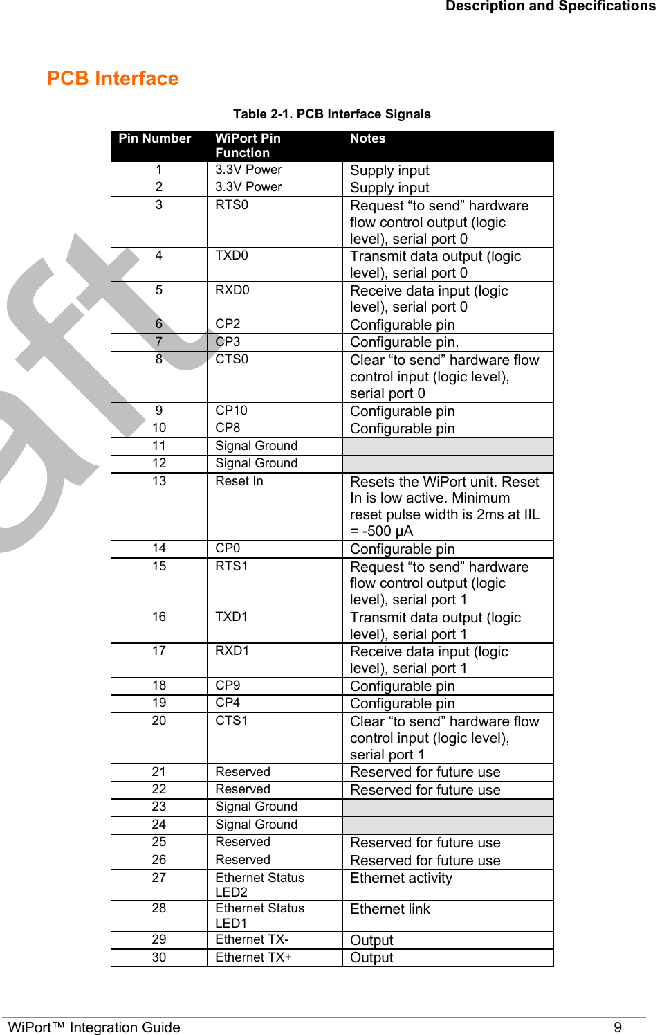
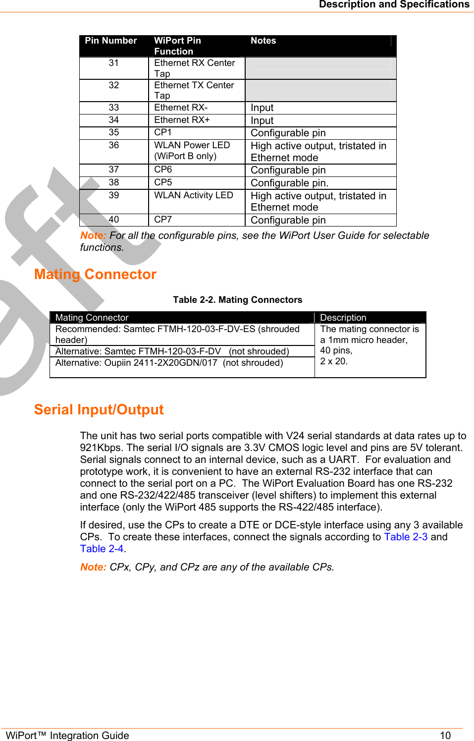
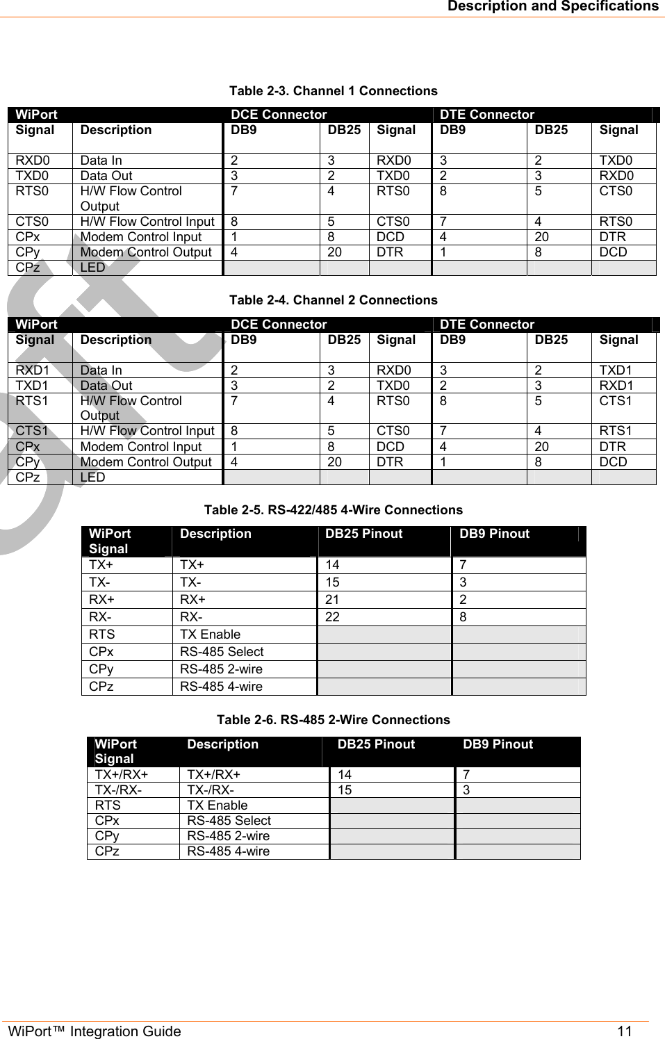
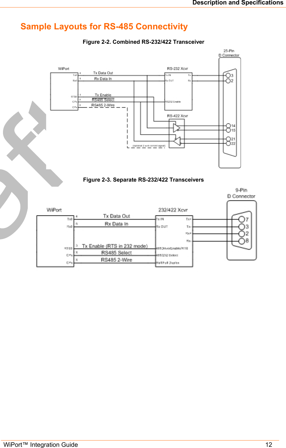
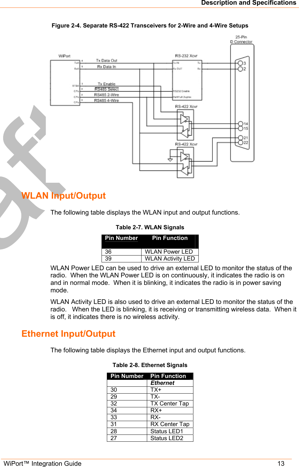
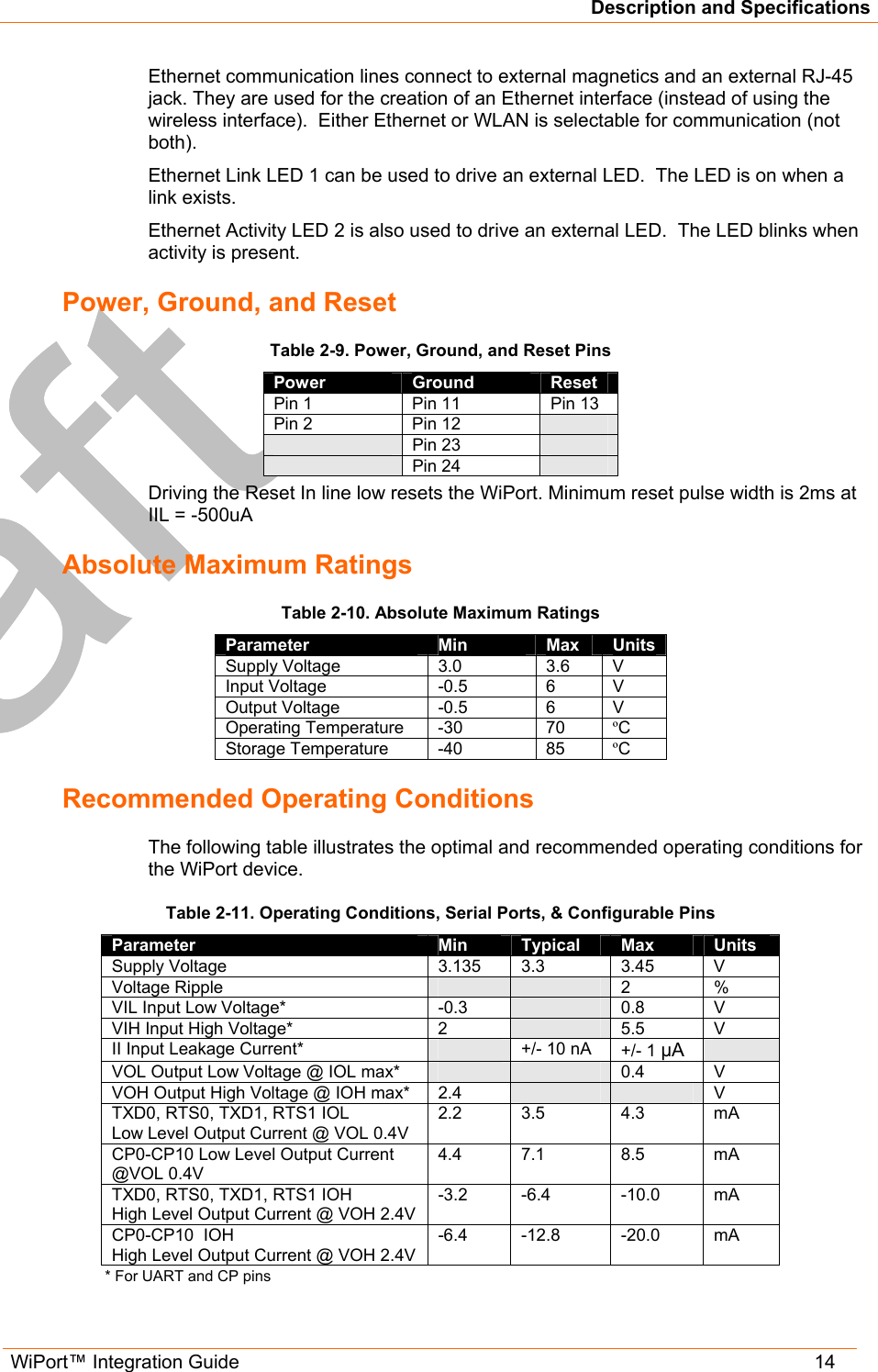
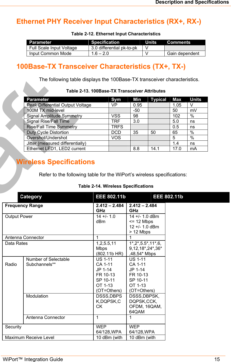
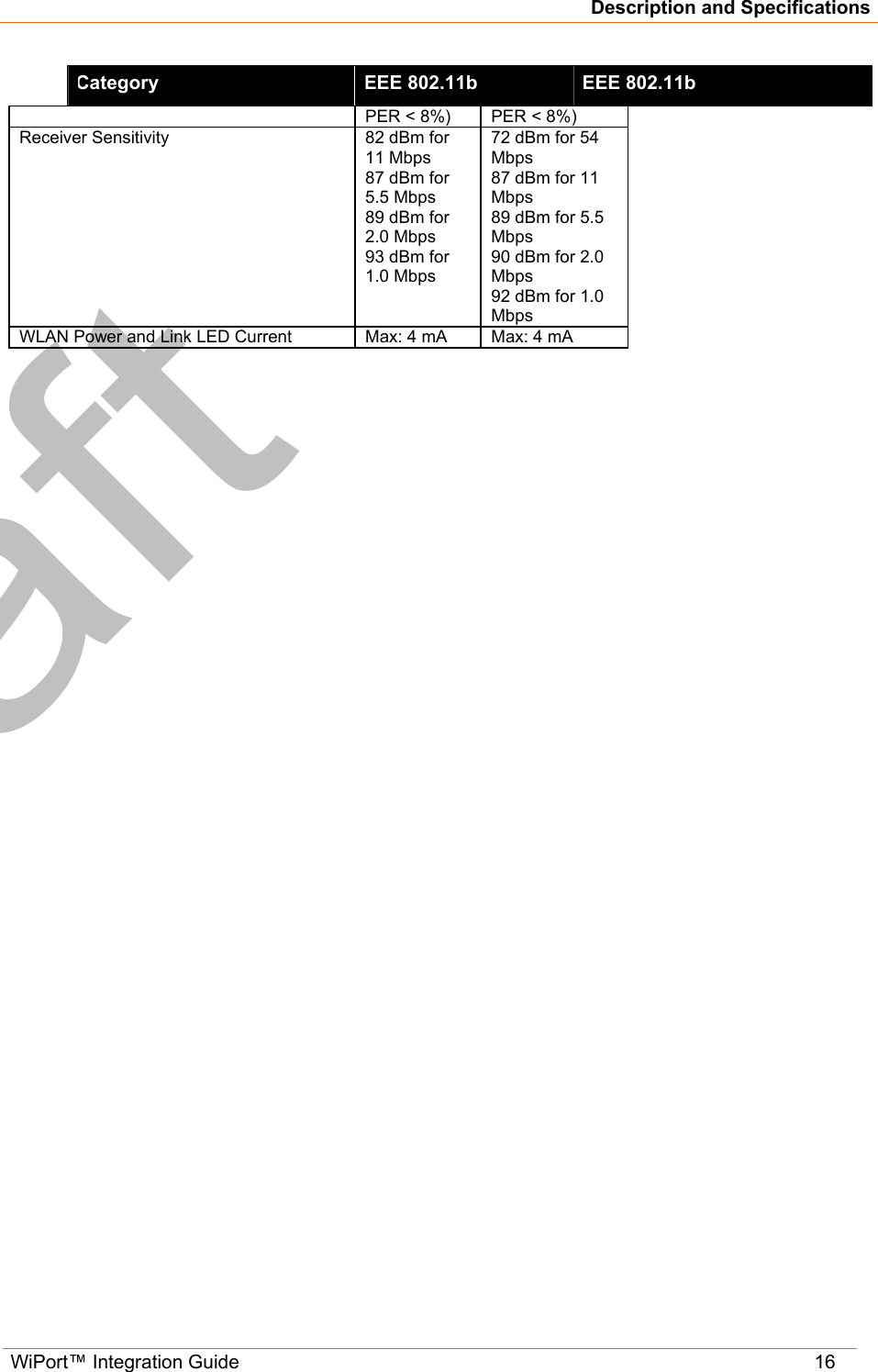
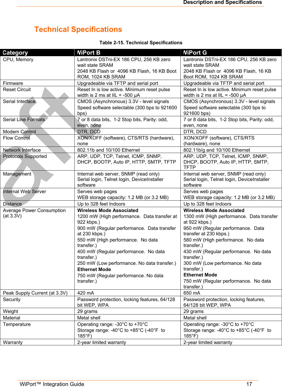
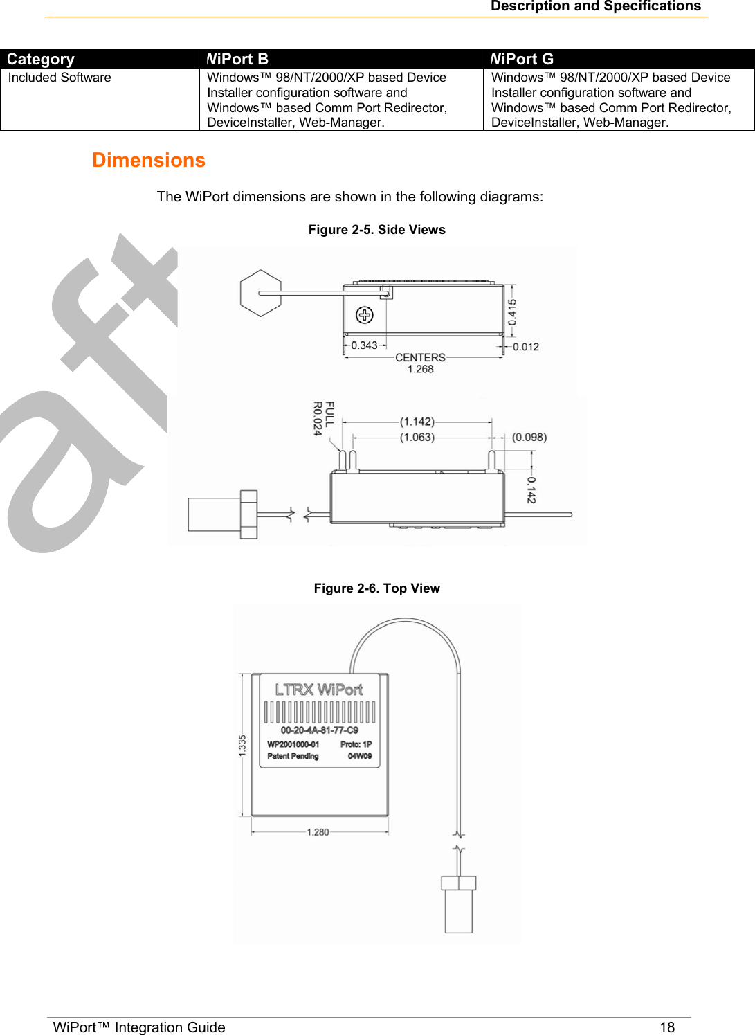
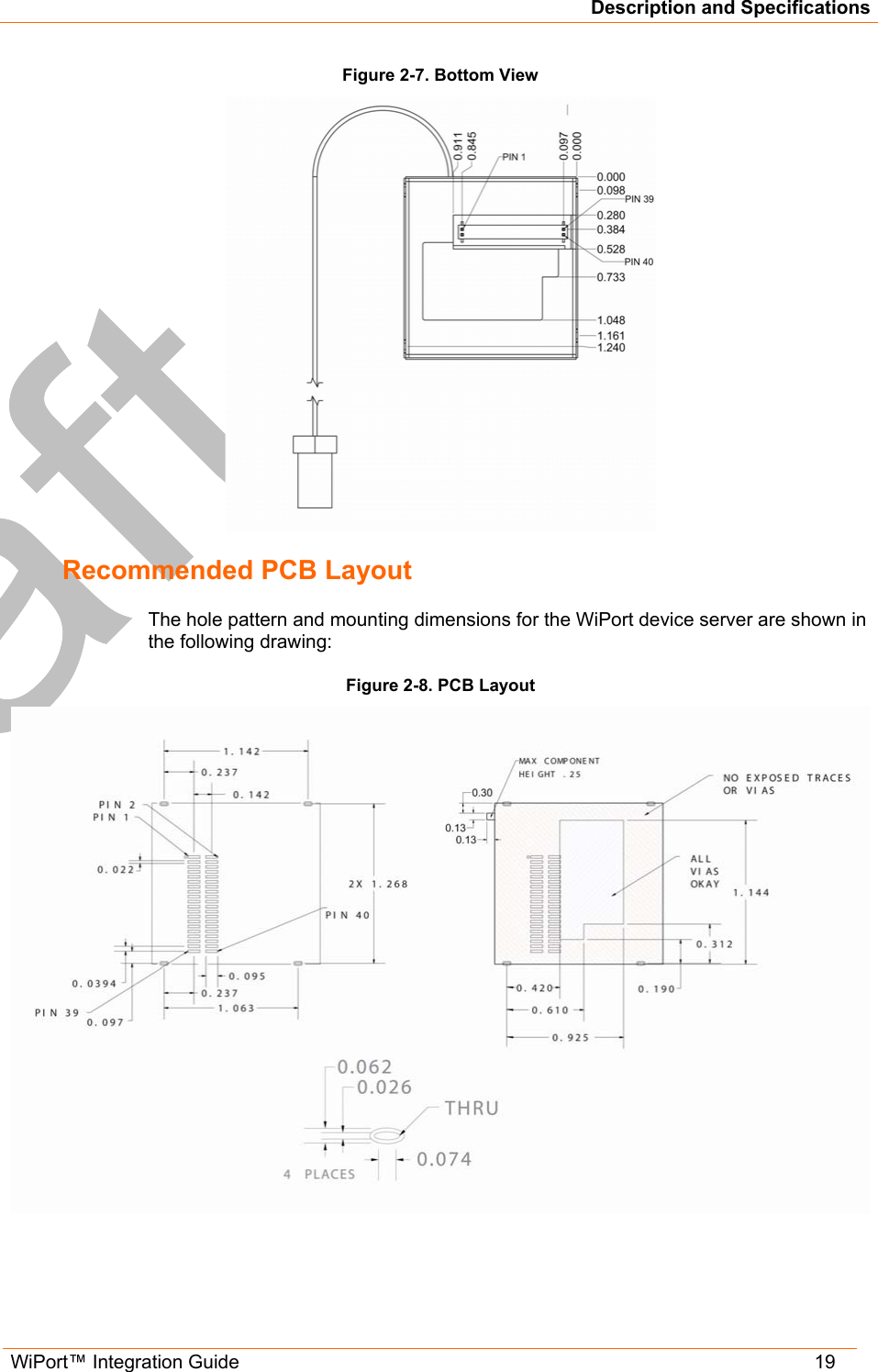
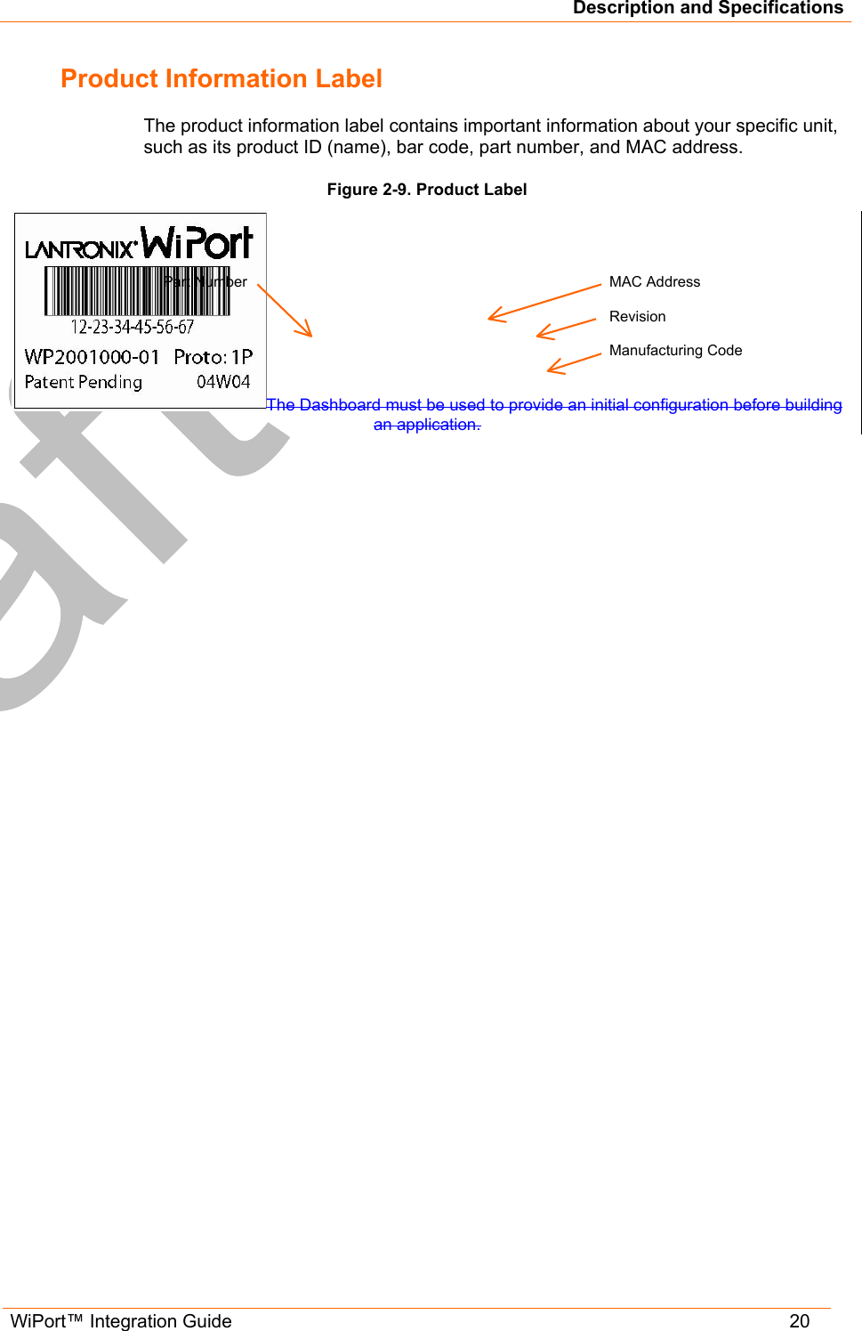
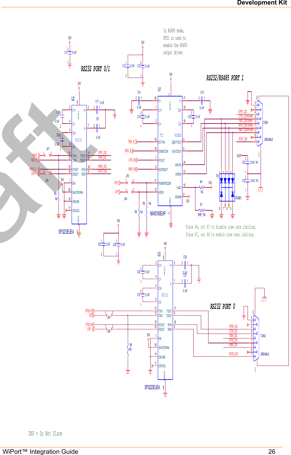
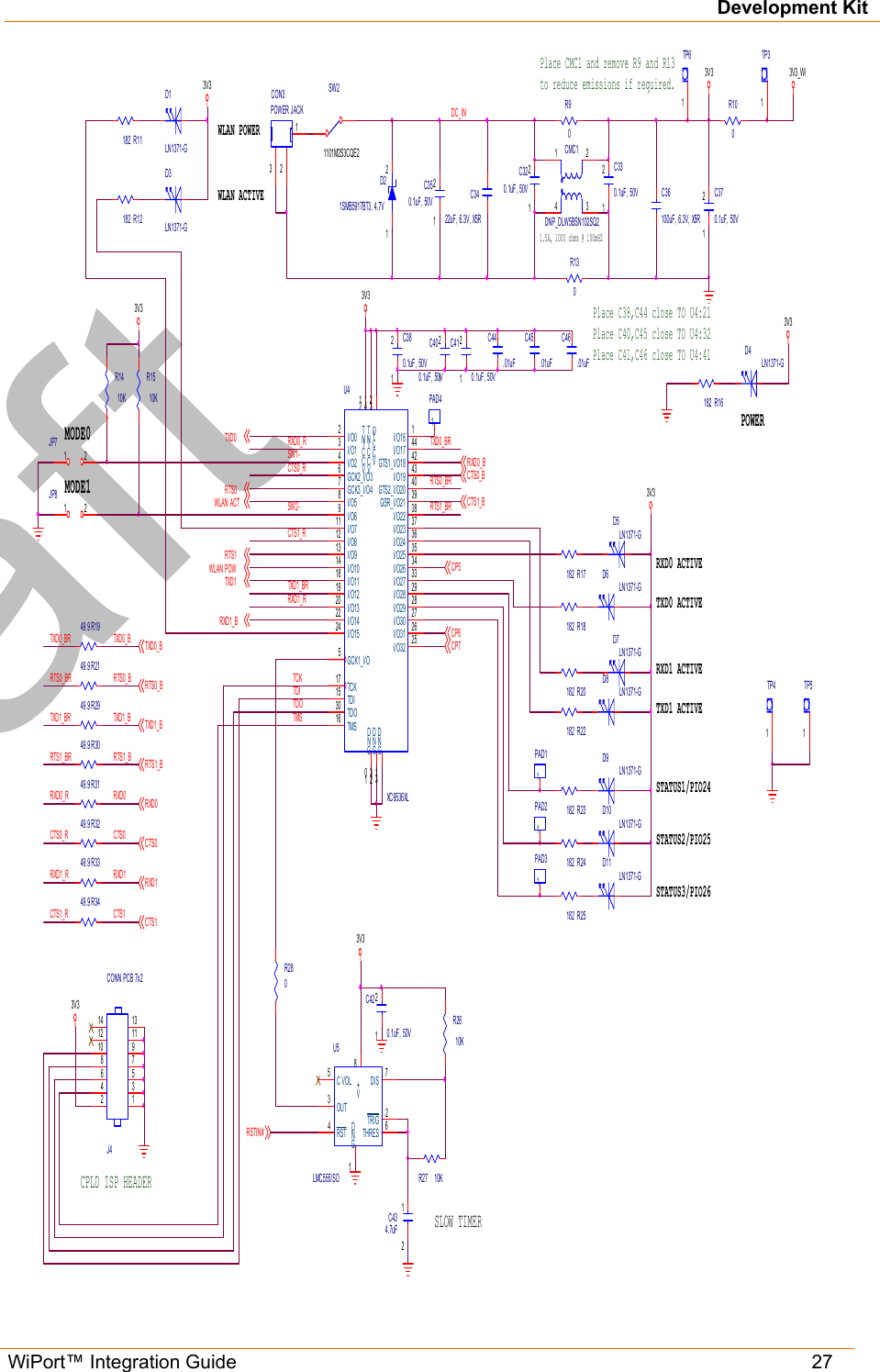
integration guide
2.
users guide
3.
USERS GUIDE
integration guide
Navigation menu
Upload a User Manual
Namespaces
Wiki Guide
HTML
PDF
Info
Views
User Manual
Discussion / Help
Navigation