metraTec QR15HL RFID Module User Manual TU5200 ISO

metraTec GmbH RFID Module TU5200 ISO

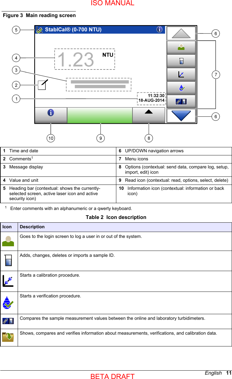
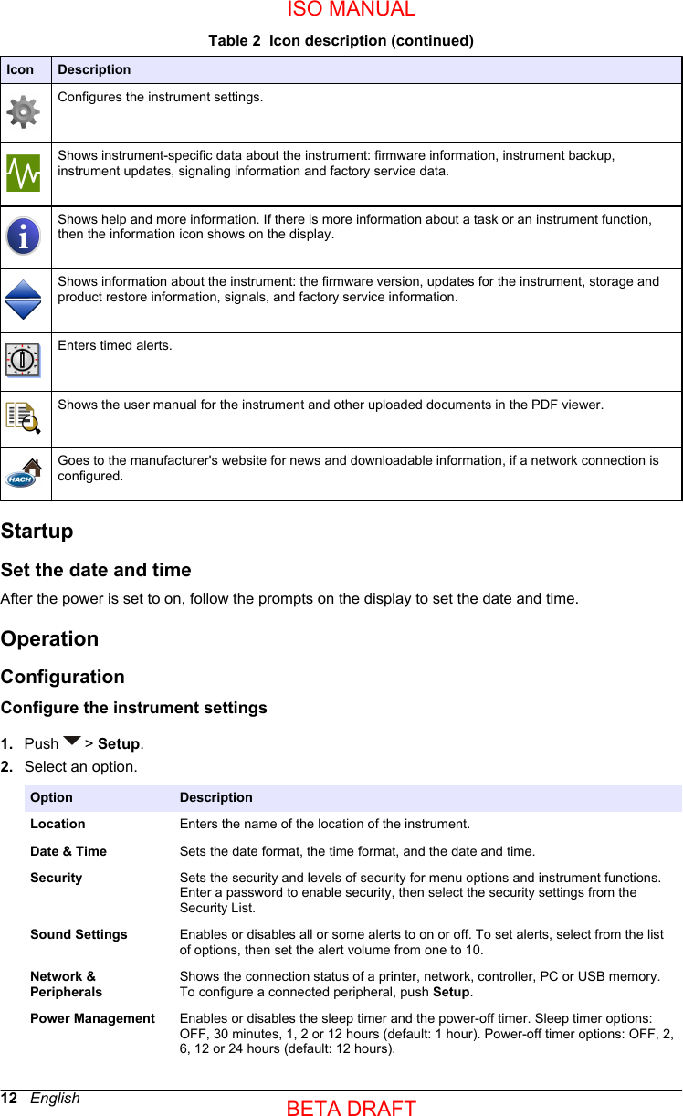
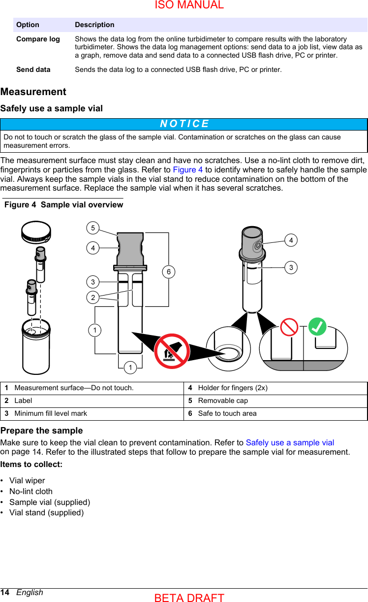
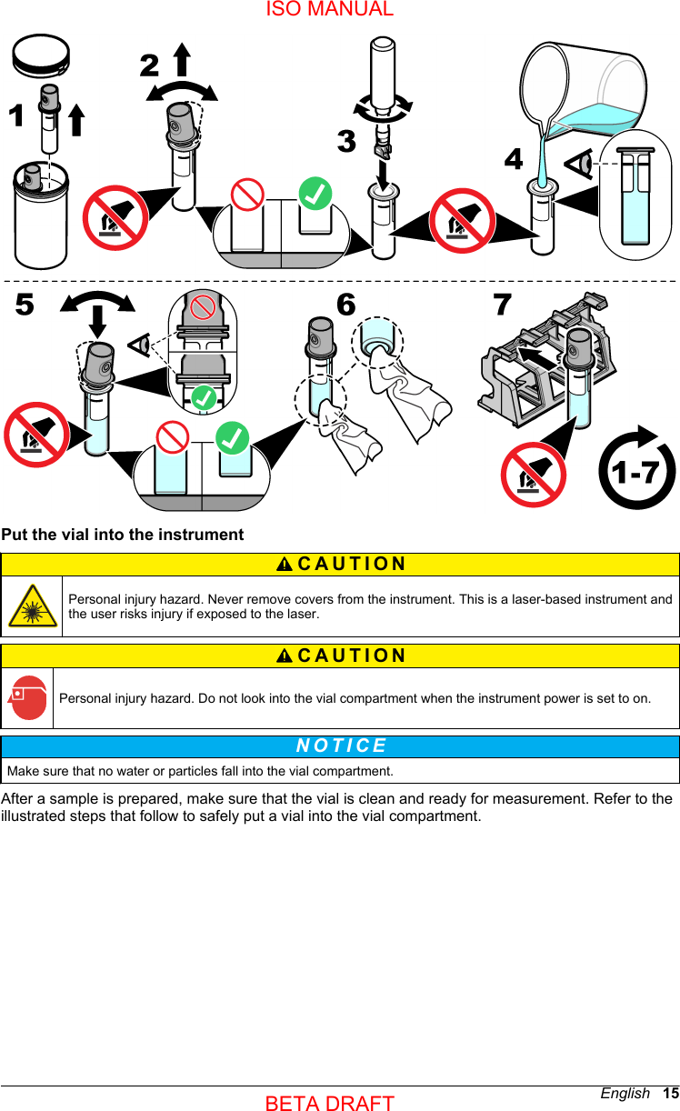
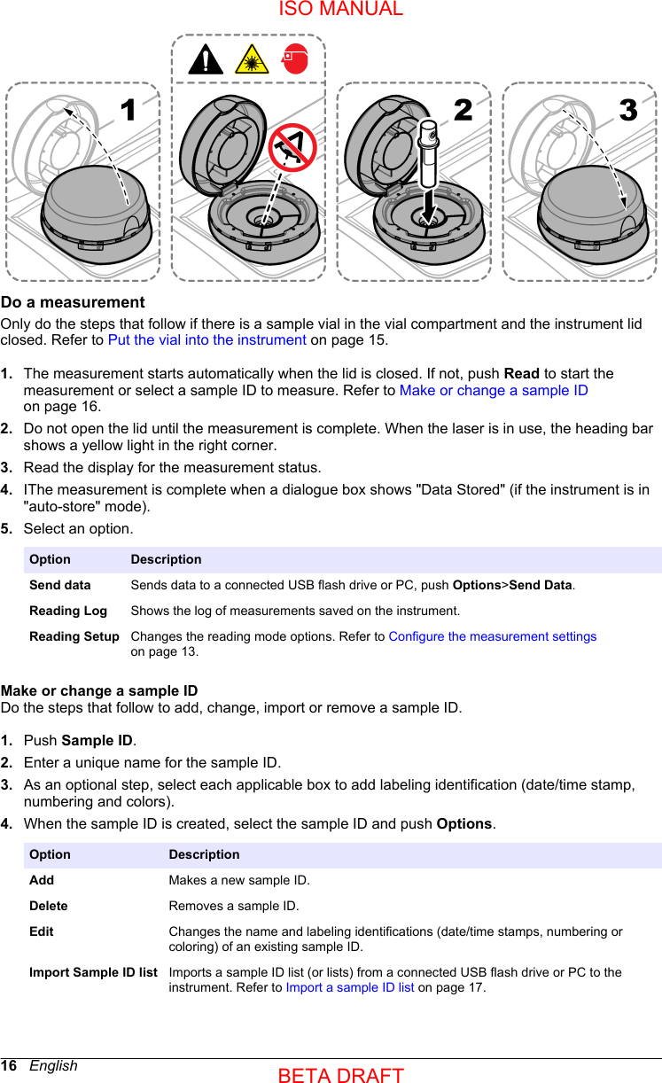
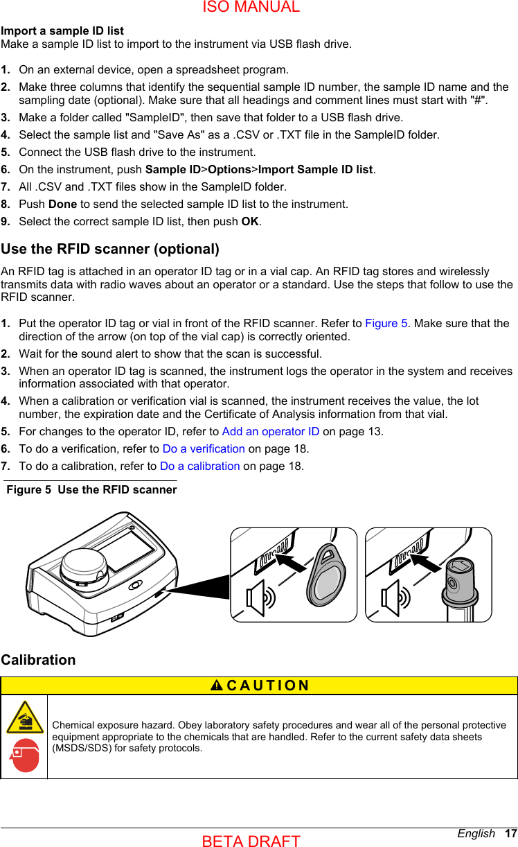
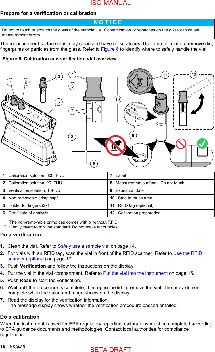
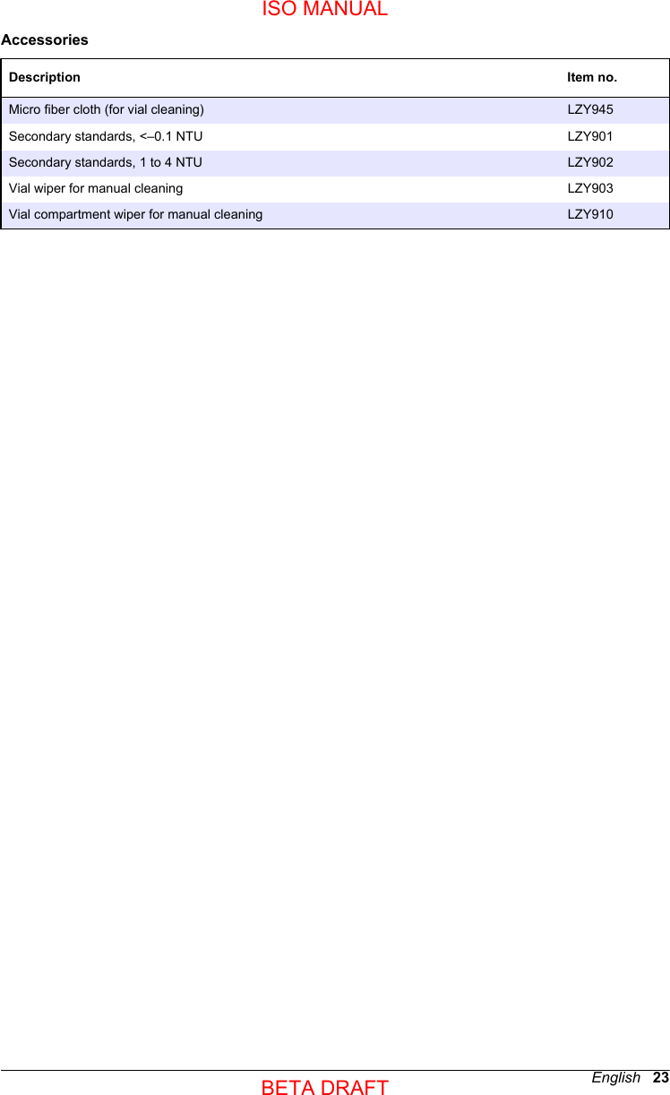
user manual TU5200 ISO

DOC022.53.80489TU520009/2014, Edition 1User ManualISO MANUALBETA DRAFT
ISO MANUALBETA DRAFT
Table of ContentsSpecifications..............................................................................................................3General information..................................................................................................4Safety information........................................................................................................4Use of hazard information....................................................................................4Precautionary labels.............................................................................................5Class 1 laser product............................................................................................5RFID module........................................................................................................6Safety information for RFID modules............................................................6FCC conformance for RFID........................................................................... 6Certification ........................................................................................................... 7Product overview.........................................................................................................7Product components....................................................................................................8Installation.....................................................................................................................9Installation guidelines..................................................................................................9Electrical installation....................................................................................................9Connect to external devices (optional).................................................................9Connect to power...............................................................................................10User interface and navigation............................................................................10Display description..................................................................................................... 10Startup........................................................................................................................... 12Set the date and time................................................................................................. 12Operation.....................................................................................................................12Configuration.............................................................................................................12Configure the instrument settings.......................................................................12Add an operator ID.............................................................................................13Configure the measurement settings.................................................................. 13Configure the Link2SC settings..........................................................................13Measurement.............................................................................................................14Safely use a sample vial.....................................................................................14Prepare the sample............................................................................................14Put the vial into the instrument...........................................................................15Do a measurement.............................................................................................16Make or change a sample ID......................................................................16Import a sample ID list................................................................................. 17Use the RFID scanner (optional)...............................................................................17Calibration .................................................................................................................. 17Prepare for a verification or calibration...............................................................18Do a verification..................................................................................................18Do a calibration................................................................................................... 18Data management.....................................................................................................19Configure the data log........................................................................................19Maintenance...............................................................................................................19Clean spills................................................................................................................20Clean the instrument.................................................................................................. 20Clean the vial.............................................................................................................201ISO MANUALBETA DRAFT
Clean the vial compartment.......................................................................................20Troubleshooting.......................................................................................................20Read the diagnostics information..............................................................................22Replacement parts and accessories...............................................................22Table of Contents2ISO MANUALBETA DRAFT
SpecificationsSpecifications are subject to change without notice.Specification DetailsDimensions (W x D x H) 41 x 28 x 12.5 cm (16 x 11 x 7.7 in.)Weight 2.37 kg (5.23 lb)Enclosure rating IP20 Protection class III (for the instrument and the external power supply)Pollution degree/installation category 2, IIPower connector via external powersupplyInput: 100–240 V, 50/60 HzOutput: 15 VDC, 2AAltitude 2500 to 3100 m (8202 to 10,171 ft) maximumRelative humidity 5 to 95% at different temperatures, non-condensingOperating temperature 10 to 40 °C (50 to 104 °F)Storage temperature –30 to 60 °C (–22 to 140 °F)Measurement method 90-degree nephelometry, 360 degrees around the axis of the incident lightbeamDisplay 17.8 mm (7 in.) color touch screenRegulatory compliance DIN EN ISO 7027 Laser Class 1 laser product: contains a non-user serviceable laserOptical light source 850 nm, maximum 0.79 mWMeasurement modes NTU, FNU, TE/F, FTU, EBC, mNTU or mFNURange 0 to 1000 FNUStray light <0.010  FNUAccuracy +/- 2 % of reading plus 0.01  FNU from 0 to 40  FNU 1+/- 10 % of reading from 40 to 1000 FNU1Linearity Better than 1 % 0 to 40 NTU on formazin at 25 °C (77 °F). Allows foraccurate calibration at 20  FNURepeatability ± 1% of the reading or ± 0.01  FNU, whichever value is moreSignal average time Off, 5 to 90 seconds (default=30 seconds)Detection limit 0.0003  FNUCalibration options StablCal®: at 20  FNU from 0 to 40  FNU; at 20  FNU and 600  FNU for fullrangeUser prepared formazin, SDVB, kaolin or EBC via factory-defined orcustom curvesVerification options StablCal®, formazin (0.1 to 40 NTU), Hach solid verification standardsVerification (Link2SC) Verification of the measurement value to compare values to a onlineinstrument via Link2SC.English   3ISO MANUALBETA DRAFT
Specification DetailsCertifications CE compliant; US FDA accession number: 1420492-xxx. This productcomplies with IEC/EN 60825-1 and to 21 CFR 1040.10 in accordance withLaser Notice No. 50.Warranty EU: 2 years1This is based on formazin primary standard.General informationIn no event will the manufacturer be liable for direct, indirect, special, incidental or consequentialdamages resulting from any defect or omission in this manual. The manufacturer reserves the right tomake changes in this manual and the products it describes at any time, without notice or obligation.Revised editions are found on the manufacturer’s website.Safety informationN O T I C E The manufacturer is not responsible for any damages due to misapplication or misuse of this product including,without limitation, direct, incidental and consequential damages, and disclaims such damages to the full extentpermitted under applicable law. The user is solely responsible to identify critical application risks and installappropriate mechanisms to protect processes during a possible equipment malfunction.Please read this entire manual before unpacking, setting up or operating this equipment. Payattention to all danger and caution statements. Failure to do so could result in serious injury to theoperator or damage to the equipment.Make sure that the protection provided by this equipment is not impaired. Do not use or install thisequipment in any manner other than that specified in this manual.Use of hazard informationD A N G E R Indicates a potentially or imminently hazardous situation which, if not avoided, will result in death or serious injury.WARNING Indicates a potentially or imminently hazardous situation which, if not avoided, could result in death or seriousinjury.CAUTION Indicates a potentially hazardous situation that may result in minor or moderate injury.N O T I C E Indicates a situation which, if not avoided, may cause damage to the instrument. Information that requires specialemphasis.4   EnglishISO MANUALBETA DRAFT
Precautionary labelsRead all labels and tags attached to the instrument. Personal injury or damage to the instrumentcould occur if not observed. A symbol on the instrument is referenced in the manual with aprecautionary statement.Electrical equipment marked with this symbol may not be disposed of in European domestic or publicdisposal systems. Return old or end-of-life equipment to the manufacturer for disposal at no charge tothe user.This symbol, if noted on the instrument, references the instruction manual for operation and/or safetyinformation.This symbol indicates that a risk of electrical shock and/or electrocution exists.This symbol indicates the need for protective eye wear.This symbol indicates a laser device is used in the equipment.This symbol identifies a risk of chemical harm and indicates that only individuals qualified and trainedto work with chemicals should handle chemicals or perform maintenance on chemical deliverysystems associated with the equipment.This symbol indicates radio waves.Class 1 laser productD A N G E R Personal injury hazard. Never remove covers from the instrument. This is a laser-based instrument andthe user risks injury if exposed to the laser.Class 1 laser product, IEC60825-1:2007, 860nm/max. 0,79mWLocation: Rear of the instrument.Conforms to U.S. regulations 21 CFR 1040.10 and 1040.11 in accordance withLaser Notice No. 50.Location: Rear of the instrument.English   5ISO MANUALBETA DRAFT
This instrument is a Class 1 Laser product. There is invisible laser radiation when the instrument isdefective and when the instrument lid is open. This product complies with EN 61010-1, "SafetyRequirements for Electrical Equipment for Measurement, Control and Laboratory Use" and withIEC/EN 60825-1, "Safety of Laser Products" and with 21 CFR 1040.10 in accordance with LaserNotice No. 50. Refer to the labels on the instrument that supply laser information.RFID moduleAn optional RFID module is available for this instrument. RFID technology is a radio application.Radio applications are subject to national conditions of authorization. The use of the sensor iscurrently permitted in the following countries: EU. The manufacturer advises that the use of thesensor outside of the above-mentioned regions may contravene national laws. The manufacturerreserves the right also to obtain authorization in other countries. In case of doubt, contact themanufacturer.The sensor contains an RFID module to receive and transmit information and data. The RFIDmodule operates with a frequency of 13.56 MHz.Safety information for RFID modulesWARNING Multiple hazards. Do not disassemble the instrument for maintenance. If the internal components mustbe cleaned or repaired, contact the manufacturer.WARNING Electromagnetic radiation hazard. Do not use the instrument in dangerous environments.N O T I C E This instrument is sensitive to electromagnetic and electromechanical interference. These interferences can havean effect on the analysis performance of this instrument. Do not put this instrument near equipment that cancause interference.Obey the safety information that follows to operate the instrument in accordance with local, regionaland national requirements.•Do not operate the instrument in hospitals and comparable establishments or near medicalequipment, such as pace makers or hearing aids.• Do not operate the instrument near highly flammable substances, such as fuels, highly flammablechemicals and explosives.• Do not operate the instrument near combustible gases, vapors or dust.• Keep the instrument away from strong vibration or shock.• The instrument can cause interference in immediate proximity to televisions, radios andcomputers.• The warranty does not cover improper use or wear.FCC conformance for RFIDThis instrument may contain a registered radio frequency identification device (RFID). Refer to Table 1 for the Federal Communications Commission (FCC) registration information.Table 1  Registration informationParameter ValueFCC identification number (FCC ID) YCB-ZBA987 IC 5879A-ZBA987 Frequency 13.56 MHz6   EnglishISO MANUALBETA DRAFT
CertificationCanadian Radio Interference-Causing Equipment Regulation, IECS-003, Class A:Supporting test records reside with the manufacturer.This Class A digital apparatus meets all requirements of the Canadian Interference-CausingEquipment Regulations.Cet appareil numérique de classe A répond à toutes les exigences de la réglementation canadiennesur les équipements provoquant des interférences.FCC Part 15, Class "A" LimitsSupporting test records reside with the manufacturer. The device complies with Part 15 of the FCCRules. Operation is subject to the following conditions:1. The equipment may not cause harmful interference.2. The equipment must accept any interference received, including interference that may causeundesired operation.Changes or modifications to this equipment not expressly approved by the party responsible forcompliance could void the user's authority to operate the equipment. This equipment has been testedand found to comply with the limits for a Class A digital device, pursuant to Part 15 of the FCC rules.These limits are designed to provide reasonable protection against harmful interference when theequipment is operated in a commercial environment. This equipment generates, uses and canradiate radio frequency energy and, if not installed and used in accordance with the instructionmanual, may cause harmful interference to radio communications. Operation of this equipment in aresidential area is likely to cause harmful interference, in which case the user will be required tocorrect the interference at their expense. The following techniques can be used to reduceinterference problems:1. Disconnect the equipment from its power source to verify that it is or is not the source of theinterference.2. If the equipment is connected to the same outlet as the device experiencing interference, connectthe equipment to a different outlet.3. Move the equipment away from the device receiving the interference.4. Reposition the receiving antenna for the device receiving the interference.5. Try combinations of the above.Product overviewD A N G E R Chemical exposure hazard. Obey laboratory safety procedures and wear all of the personal protectiveequipment appropriate to the chemicals that are handled. Refer to the current safety data sheets(MSDS/SDS) for safety protocols.The TU5200 turbidimeter measures low turbidity primarily in drinking water applications. Thislaboratory instrument is factory calibrated and measures scattered light at an angle of 90 degrees,360 degrees around the axis of the incident light beam. Use the touch screen to operate theinstrument. Refer to Figure 1.English   7ISO MANUALBETA DRAFT
Figure 1  Product overview1   Lid 6   USB port type A2   Vial compartment 7   USB port type B3   Display screen 8   Ethernet port4   Power button 9   RFID scanner (optional)5   Power connection 10   USB port type AProduct componentsMake sure that all components have been received. Refer to Figure 2. If any items are missing ordamaged, contact the manufacturer or a sales representative immediately.8   EnglishISO MANUALBETA DRAFT
Figure 2  Product components1   Turbidimeter 4   Power supply with adapters2   StablCal® calibration set 5   Dust cover3   Sample vials 6   Vial standInstallationCAUTION Multiple hazards. Only qualified personnel must conduct the tasks described in this section of thedocument.This instrument is rated for an altitude of 2000 m (6562 ft) maximum. Use of this instrument at analtitude higher than 2000 m can slightly increase the potential for the insulation to breakdown, whichcan result in an electric shock hazard. The manufacturer recommends that users with concernscontact technical support.Installation guidelinesInstall the instrument:•On a level surface• In a clean, dry, well ventilated, temperature controlled location• In a location with minimum vibrations that has no direct exposure to sunlight• In a location where there is sufficient clearance around it to make connections and to domaintenance tasks• In a location where the power button and power cord are visible and easily accessibleElectrical installationConnect to external devices (optional)The instrument has three USB ports and one ethernet port. Refer to Figure 1 on page 8. Refer to theoptional external device documentation for more information.• USB port—Connect to a printer, scanner, USB flash drive or a flow-through module.• Ethernet port—Connect to an external PC or a communications network.English   9ISO MANUALBETA DRAFT
Connect to powerCAUTION Personal injury hazard. Never remove covers from the instrument. This is a laser-based instrument andthe user risks injury if exposed to the laser.CAUTION Personal injury hazard. Do not look into the vial compartment when the instrument power is set to on.Refer to the illustrated steps that follow to connect power to the instrument and start the instrument.User interface and navigationDisplay descriptionRefer to Figure 3 for the home screen description. Refer to Table 2 for the icon description. Do notuse writing tips of pens or pencils or other sharp objects to make selections on the screen. Only usea clean, dry finger tip to navigate the functions of the touch screen.10   EnglishISO MANUALBETA DRAFT
Figure 3  Main reading screen1   Time and date 6   UP/DOWN navigation arrows2   Comments17   Menu icons3   Message display 8   Options (contextual: send data, compare log, setup,import, edit) icon4   Value and unit 9   Read icon (contextual: read, options, select, delete)5   Heading bar (contextual: shows the currently-selected screen, active laser icon and activesecurity icon)10   Information icon (contextual: information or backicon)1Enter comments with an alphanumeric or a qwerty keyboard.Table 2  Icon descriptionIcon DescriptionGoes to the login screen to log a user in or out of the system.Adds, changes, deletes or imports a sample ID.Starts a calibration procedure.Starts a verification procedure.Compares the sample measurement values between the online and laboratory turbidimeters.Shows, compares and verifies information about measurements, verifications, and calibration data.English   11ISO MANUALBETA DRAFT
Table 2  Icon description (continued)Icon DescriptionConfigures the instrument settings.Shows instrument-specific data about the instrument: firmware information, instrument backup,instrument updates, signaling information and factory service data.Shows help and more information. If there is more information about a task or an instrument function,then the information icon shows on the display.Shows information about the instrument: the firmware version, updates for the instrument, storage andproduct restore information, signals, and factory service information.Enters timed alerts.Shows the user manual for the instrument and other uploaded documents in the PDF viewer.Goes to the manufacturer's website for news and downloadable information, if a network connection isconfigured.StartupSet the date and timeAfter the power is set to on, follow the prompts on the display to set the date and time.OperationConfigurationConfigure the instrument settings1. Push   > Setup.2. Select an option.Option DescriptionLocation Enters the name of the location of the instrument.Date & Time Sets the date format, the time format, and the date and time.Security Sets the security and levels of security for menu options and instrument functions.Enter a password to enable security, then select the security settings from theSecurity List.Sound Settings Enables or disables all or some alerts to on or off. To set alerts, select from the listof options, then set the alert volume from one to 10.Network &PeripheralsShows the connection status of a printer, network, controller, PC or USB memory.To configure a connected peripheral, push Setup.Power Management Enables or disables the sleep timer and the power-off timer. Sleep timer options:OFF, 30 minutes, 1, 2 or 12 hours (default: 1 hour). Power-off timer options: OFF, 2,6, 12 or 24 hours (default: 12 hours).12   EnglishISO MANUALBETA DRAFT
Add an operator ID1. Push Login>Options.2. Select an option.Option DescriptionNew Adds a unique operator ID.Edit Changes an existing operator ID and assigns a security level to an operator ID.Delete Removes an existing operator ID.Initialize RFIDtagEnables an operator ID tag (optional) to be initialized. Refer to Use the RFID scanner(optional) on page 17. Select an existing operator ID, then put the operator ID tag infront of the RFID scanner. The screen shows the when RFID tag is activated.To overwrite an operator ID tag and assign it to a different operator, follow the instructionson the display.3. Push Save or Cancel.Configure the measurement settings1. At the main reading screen, push Options>Reading Setup.2. Select an option.Option DescriptionReading Sets the reading mode to single (default) or continuous. Sets the signal averaging timeto on (5 to 15 seconds) or off for a single reading. Sets the signal averaging time to on(5 to 90 seconds) or off for a continuous reading.Unit Selects the measurement units that are shown on the display and in the data log.Options: NTU, FNU, TE/F, FTU, EBC, mNTU or mFNU (default: FNU)Data Log Setup Sets the automatic storage settings, comments and automatic send to on or off. Setsthe data format storage to CSV or XML (default). Sets the print format to quick print ordetailed print (GLP) (default).Resolution Selects the number of decimal places shown in a calculation result. Options:0.001 (default) or 0.0001.Bubble Reject Sets the bubble reject to on (default) or off. When it is set to on, an algorithm is used toremove the influence of bubbles in the sample.Close lid to startreadingSets the instrument to on (default) or off to immediately start a reading when a vial is inthe vial compartment and the lid is closed.Configure the Link2SC settingsLink2SC is a secure networking method for the data exchange between the online and laboratoryturbidimeters. Refer to the online turbidimeter documentation to create a new job or select the job listto send to the laboratory turbidimeter. Use the RFID option, a LAN connection or an SD memory cardfor the data exchange. Refer to the Link2SC documentation on the manufacturer's website for adetailed description of the Link2SC procedure.1. Push LINK2SC>Compare.2. Select an option.Option DescriptionLINK2SC Setup Sets the acceptance range by value 1 to 50% (default: 10%) in NTU 0.001 to 100.0 NTU.English   13ISO MANUALBETA DRAFT
Option DescriptionCompare log Shows the data log from the online turbidimeter to compare results with the laboratoryturbidimeter. Shows the data log management options: send data to a job list, view data asa graph, remove data and send data to a connected USB flash drive, PC or printer.Send data Sends the data log to a connected USB flash drive, PC or printer.MeasurementSafely use a sample vialN O T I C E Do not to touch or scratch the glass of the sample vial. Contamination or scratches on the glass can causemeasurement errors.The measurement surface must stay clean and have no scratches. Use a no-lint cloth to remove dirt,fingerprints or particles from the glass. Refer to Figure 4 to identify where to safely handle the samplevial. Always keep the sample vials in the vial stand to reduce contamination on the bottom of themeasurement surface. Replace the sample vial when it has several scratches.Figure 4  Sample vial overview1   Measurement surface—Do not touch. 4   Holder for fingers (2x)2   Label 5   Removable cap3   Minimum fill level mark 6   Safe to touch areaPrepare the sampleMake sure to keep the vial clean to prevent contamination. Refer to Safely use a sample vialon page 14. Refer to the illustrated steps that follow to prepare the sample vial for measurement.Items to collect:• Vial wiper• No-lint cloth• Sample vial (supplied)• Vial stand (supplied)14   EnglishISO MANUALBETA DRAFT
Put the vial into the instrumentCAUTION Personal injury hazard. Never remove covers from the instrument. This is a laser-based instrument andthe user risks injury if exposed to the laser.CAUTION Personal injury hazard. Do not look into the vial compartment when the instrument power is set to on.N O T I C E Make sure that no water or particles fall into the vial compartment.After a sample is prepared, make sure that the vial is clean and ready for measurement. Refer to theillustrated steps that follow to safely put a vial into the vial compartment.English   15ISO MANUALBETA DRAFT
Do a measurementOnly do the steps that follow if there is a sample vial in the vial compartment and the instrument lidclosed. Refer to Put the vial into the instrument on page 15.1. The measurement starts automatically when the lid is closed. If not, push Read to start themeasurement or select a sample ID to measure. Refer to Make or change a sample IDon page 16.2. Do not open the lid until the measurement is complete. When the laser is in use, the heading barshows a yellow light in the right corner.3. Read the display for the measurement status.4. IThe measurement is complete when a dialogue box shows "Data Stored" (if the instrument is in"auto-store" mode).5. Select an option.Option DescriptionSend data Sends data to a connected USB flash drive or PC, push Options>Send Data.Reading Log Shows the log of measurements saved on the instrument.Reading Setup Changes the reading mode options. Refer to Configure the measurement settingson page 13.Make or change a sample IDDo the steps that follow to add, change, import or remove a sample ID.1. Push Sample ID.2. Enter a unique name for the sample ID.3. As an optional step, select each applicable box to add labeling identification (date/time stamp,numbering and colors).4. When the sample ID is created, select the sample ID and push Options.Option DescriptionAdd Makes a new sample ID.Delete Removes a sample ID.Edit Changes the name and labeling identifications (date/time stamps, numbering orcoloring) of an existing sample ID.Import Sample ID list Imports a sample ID list (or lists) from a connected USB flash drive or PC to theinstrument. Refer to Import a sample ID list on page 17.16   EnglishISO MANUALBETA DRAFT
Import a sample ID listMake a sample ID list to import to the instrument via USB flash drive.1. On an external device, open a spreadsheet program.2. Make three columns that identify the sequential sample ID number, the sample ID name and thesampling date (optional). Make sure that all headings and comment lines must start with "#".3. Make a folder called "SampleID", then save that folder to a USB flash drive.4. Select the sample list and "Save As" as a .CSV or .TXT file in the SampleID folder.5. Connect the USB flash drive to the instrument.6. On the instrument, push Sample ID>Options>Import Sample ID list.7. All .CSV and .TXT files show in the SampleID folder.8. Push Done to send the selected sample ID list to the instrument.9. Select the correct sample ID list, then push OK.Use the RFID scanner (optional)An RFID tag is attached in an operator ID tag or in a vial cap. An RFID tag stores and wirelesslytransmits data with radio waves about an operator or a standard. Use the steps that follow to use theRFID scanner.1. Put the operator ID tag or vial in front of the RFID scanner. Refer to Figure 5. Make sure that thedirection of the arrow (on top of the vial cap) is correctly oriented.2. Wait for the sound alert to show that the scan is successful.3. When an operator ID tag is scanned, the instrument logs the operator in the system and receivesinformation associated with that operator.4. When a calibration or verification vial is scanned, the instrument receives the value, the lotnumber, the expiration date and the Certificate of Analysis information from that vial.5. For changes to the operator ID, refer to Add an operator ID on page 13.6. To do a verification, refer to Do a verification on page 18.7. To do a calibration, refer to Do a calibration on page 18.Figure 5  Use the RFID scannerCalibrationCAUTION Chemical exposure hazard. Obey laboratory safety procedures and wear all of the personal protectiveequipment appropriate to the chemicals that are handled. Refer to the current safety data sheets(MSDS/SDS) for safety protocols.English   17ISO MANUALBETA DRAFT
Prepare for a verification or calibrationN O T I C E Do not to touch or scratch the glass of the sample vial. Contamination or scratches on the glass can causemeasurement errors.The measurement surface must stay clean and have no scratches. Use a no-lint cloth to remove dirt,fingerprints or particles from the glass. Refer to Figure 6 to identify where to safely handle the vial.Figure 6  Calibration and verification vial overview1   Calibration solution, 600  FNU 7   Label2   Calibration solution, 20  FNU 8   Measurement surface—Do not touch.3   Verification solution, 10FNU 9   Expiration date4   Non-removable crimp cap110   Safe to touch area5   Holder for fingers (2x) 11   RFID tag (optional)6   Certificate of analysis 12   Calibration preparation21The non-removable crimp cap comes with or without RFID.2Gently invert to mix the standard. Do not make air bubbles.Do a verification1. Clean the vial. Refer to Safely use a sample vial on page 14.2. For vials with an RFID tag, scan the vial in front of the RFID scanner. Refer to Use the RFIDscanner (optional) on page 17.3. Push Verification and follow the instructions on the display.4. Put the vial in the vial compartment. Refer to Put the vial into the instrument on page 15.5. Push Read to start the verification.6. Wait until the procedure is complete, then open the lid to remove the vial. The procedure iscomplete when the value and range shows on the display.7. Read the display for the verification information.The message display shows whether the verification procedure passed or failed.Do a calibrationWhen the instrument is used for EPA regulatory reporting, calibrations must be completed accordingto EPA guidance documents and methodologies. Contact local authorities for complianceregulations.18   EnglishISO MANUALBETA DRAFT
The instrument is factory calibrated. Do calibration procedures as necessary. Do the steps that followto do a full range calibration procedure.1. Clean the vial, then carefully invert the vial. Do not cause air bubbles. Refer to Prepare for averification or calibration on page 18.2. For vials with an RFID tag, scan the vial in front of the RFID scanner. Refer to Use the RFIDscanner (optional) on page 17.3. Push Calibration and follow the instructions on the display.4. Put the vial in the vial compartment. Refer to Put the vial into the instrument on page 15.5. Push Read to start the calibration.6. Wait until the procedure is complete, then open the lid to remove the vial. The procedure iscomplete when the value and range shows on the display.7. Remove the first calibration vial, then do steps 1 to 5 again for the second calibration vial.8. Read the display for the calibration information.9. Push Store to complete the calibration and keep the results.Data managementConfigure the data logThe data log keeps all saved comments and readings from measurements, calibrations andverifications. Use the steps that follow to select, manage and store data.1. Push Data Log and select a data log to show.2. Select an option.Option DescriptionFilter Sets the data filtering to on or off. If on, select and arrange data by time interval or operator ID.View details Shows information about a selected data log. Push the comments icon to enter any necessaryinformation.Options Shows the current options (contextual). View Graph—See data as a graph, set control limits toon or off (0.800 = upper control limit or 0.200 = lower control limit). Add data—Select a sampleID to add to the graph. Curve style(???WHAT IS THE PROPER NOUN???)—Selects thecurve style as crosses, rectangular dots or a line. Delete—Removes selected data from thedata log. Send data—Sends selected data to a connected USB flash drive or PC.MaintenanceCAUTION Multiple hazards. Only qualified personnel must conduct the tasks described in this section of thedocument.CAUTION Chemical exposure hazard. Obey laboratory safety procedures and wear all of the personal protectiveequipment appropriate to the chemicals that are handled. Refer to the current safety data sheets(MSDS/SDS) for safety protocols.CAUTION Personal injury hazard. Never remove covers from the instrument. This is a laser-based instrument andthe user risks injury if exposed to the laser.English   19ISO MANUALBETA DRAFT
N O T I C E Do not disassemble the instrument for maintenance. If the internal components must be cleaned or repaired,contact the manufacturer.Clean spillsCAUTION Chemical exposure hazard. Dispose of chemicals and wastes in accordance with local, regional andnational regulations.1. Obey all facility safety protocols for spill control.2. Discard the waste according to applicable regulations.Clean the instrumentClean the exterior of the instrument with a moist cloth, and then wipe the instrument dry.Clean the vialUse a vial wiper to clean the interior of the vial. Refer to Safely use a sample vial on page 14 to cleanthe exterior of the vial.Clean the vial compartmentD A N G E R Electrocution hazard. Remove power from the instrument before this procedure is started.Periodically clean the vial compartment to manually remove dust with a bellow, air duster, brush orvial compartment wiper. Make sure that the tool to clean the vial compartment has a soft surface anddoes not damage the instrument. Make sure to remove power to the instrument before the cleaningstarts.TroubleshootingProblem Possible cause SolutionThe self-check stopped or theinstrument does not operate.A hardware error. Set the instrument to off, then to on again. Ifnecessary, contact technical support.The instrument lid is open. Close the lid, then start the self-check again.The vial compartment is dirty. Refer to Clean the vial compartmenton page 20. If necessary, contact technicalsupport.The optical light source is notstable.Contact technical support.An "over measuring range"message shows.The instrument is only singlecalibrated at 40 NTU and thesample is between 40 to1000 FNU???WHAT IS THE SOLUTION???The range of the sample is overthe measuring range of theinstrument???WHAT IS THE SOLUTION???20   EnglishISO MANUALBETA DRAFT
Problem Possible cause SolutionThe standard value is too high. The wrong standard is in thevial compartment.Check the calibration standard and Do acalibration on page 18.There are bubbles in thestandard.???WHAT IS THE SOLUTION???There is dirt in the vialcompartment.Clean the vial compartment on page 20.The standard value is too low. The wrong standard is in thevial compartment.Check the calibration standard. Invert thestandard and Do a calibration on page 18.???WHAT IS THEPROBLEM???The standard value is out ofrange.Put the standards in ascending order. Invertthe standard, then Do a calibrationon page 18.A "verification failure" messageshows.The verification failed. •Do a verification on page 18 again.•Do a calibration on page 18.• If the verification and calibrationprocedures do not work, then restore thefactory settings. Refer to Read thediagnostics information on page 22.The measurement valuesbetween the online andbenchtop turbidimeters do notmatch.There is dirt or condensation onthe sample vial.Refer to Safely use a sample vial on page 14to remove dirt and condensation.The service time expired. Set the bubble elimination to on. Refer to Configure the measurement settingson page 13.There is an error with the onlineturbidimeter.Refer to the documentation for the onlineturbidimeter.The instrument update fails. The USB memory is notconnected.Connect the USB flash drive. Make sure thatthe file system "FAT32" is installed on theUSB memory. Set the power to off, then toon again. Connect the USB flash drive, thenstart the update procedure again.The instrument update file orscript is corrupt or missing.Remove the USB memory files, thendownload the files again. Connect the USBmemory to the instrument, then do theupdate procedure again.The copy from the USB memoryfailed.Remove large files that use too much space.Do the update procedure again.Delete the file from the USB memory.Download the file again to the USB memory.Connect the USB memory to the instrumentand start the update procedure again.There is not enough memory toupdate the instrument.Contact technical support.A user cannot login. The password is wrong. Enter the correct password. If necessary,contact technical support.A "No valid data found"message shows.No sample ID found on the USBmemory or shared networkdrive.???WHAT IS THE SOLUTION??????WHAT IS THEPROBLEM???The sampling date, sample IDor the date format is wrong orcannot be read.Refer to Import a sample ID list on page 17.Make sure that the date is entered correctly.English   21ISO MANUALBETA DRAFT
Problem Possible cause SolutionSelected documents do notshow on the display.The document is not a PDF file. Make sure that the document is a PDF file.The network connection doesnot show.There is no connection to theDHCP server.Contact the network administrator. Ifnecessary, contact technical support.The connection was notcorrectly configured.Make sure that the settings are correctlyentered.Read the diagnostics information1. Push Diagnostics.2. Select an option.Option DescriptionInstrument Information Shows specific information such as the instrument name, serial number,instrument version, location and MAC address.Signals Shows the signals for the lid, vial, turbidity, condensation, and fouling. If a USBflash drive or PC is connected to the instrument, send data.Instrument Backup Sets the instrument backup settings to store or restore.Instrument Update Connect the USB memory into a USB port and push OK to start the instrumentupdate.Service Time Shows the last service date and the next service date.Factory Service Only used by authorized factory service personnel.Replacement parts and accessoriesWARNING Personal injury hazard. Use of non-approved parts may cause personal injury, damage to theinstrument or equipment malfunction. The replacement parts in this section are approved by themanufacturer.Note: Product and Article numbers may vary for some selling regions. Contact the appropriate distributor or refer tothe company website for contact information.Replacement partsDescription Item no.Dust cover LZV947 Power supply, 100–240 V, 50/60 Hz LZV798 StablCal calibration set (20 NTU cal, 600 NTU cal, 10 NTU ver) with RFID LZY835 StablCal calibration set (20 NTU cal, 600 NTU cal, 10 NTU ver) with no RFID LZY898 Sample vials with protective caps (2x) LZV946 Vial stand LZV952 22   EnglishISO MANUALBETA DRAFT
AccessoriesDescription Item no.Micro fiber cloth (for vial cleaning) LZY945 Secondary standards, <–0.1 NTU LZY901 Secondary standards, 1 to 4 NTU LZY902 Vial wiper for manual cleaning LZY903 Vial compartment wiper for manual cleaning LZY910 English   23ISO MANUALBETA DRAFT
24   EnglishISO MANUALBETA DRAFT
ISO MANUALBETA DRAFT
HACH COMPANY World HeadquartersP.O. Box 389, Loveland, CO 80539-0389 U.S.A.Tel. (970) 669-3050(800) 227-4224 (U.S.A. only)Fax (970) 669-2932orders@hach.comwww.hach.comHACH LANGE GMBHWillstätterstraße 11D-40549 Düsseldorf, GermanyTel. +49 (0) 2 11 52 88-320Fax +49 (0) 2 11 52 88-210info@hach-lange.dewww.hach-lange.deHACH LANGE Sàrl6, route de Compois1222 VésenazSWITZERLANDTel. +41 22 594 6400Fax +41 22 594 6499© Hach Company/Hach Lange GmbH, 2014.All rights reserved. Printed in Germany.ISO MANUALBETA DRAFT

Navigation menu