testo Instruments 05601557 Digital manifold User Manual
testo Instruments (Shenzhen) Co., Ltd Digital manifold
UserManual.wiki
>
testo Instruments
>
05601557 User Manual
user manual
Navigation menu
Upload a User Manual
Namespaces
Wiki Guide
HTML
PDF
Info
Views
User Manual
Discussion / Help
Navigation

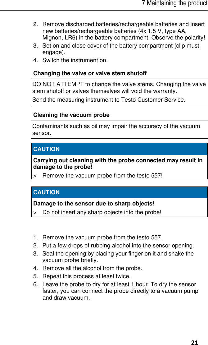
![2 Safety and the environment 4 Pos: 3 /TD/Übersc hriften/2. Sich erheit und Umwelt @ 0\mod_ 11737747193 51_79.docx @ 2 92 @ 1 @ 1 2 Safety and the environment Pos: 4 /TD/Übersc hriften/2.1 Zu di esem Dokum ent @ 0\mod _1173775252 351_79.docx @ 3 46 @ 2 @ 1 2.1. About this document Pos: 5 /TD/Sich erheit und Umwelt/Z u diesem Do kument/Ver wendung/Verwend ung (Standard) @ 0\mod_1 17377506855 4_79.docx @ 337 @ 5 @ 1 Use > Please read this documentation carefully and familiarize yourself with the product before putting it to use. Pay particular attention to the safety instructions and warning advice in order to prevent injuries and damage to the product. Pos: 6 /TD/Sich erheit und Umwelt/Z u diesem Do kument/Symb ole und Schreib konventionen/ Symbole und Schr eibkon v. [Standard_groß] @ 0\mod_1174 982140622_7 9.docx @ 515 @ 5 @ 1 Symbols and writing standards Representation Explanation Warning advice, risk level according to the signal word: Warning! Serious physical injury may occur. Caution! Slight physical injury or damage to the equipment may occur. > Implement the specified precautionary measures. Menu Elements of the instrument, the instrument display or the program interface. [OK] Control keys of the instrument or buttons of the program interface. Pos: 7 /TD/Übersc hriften/2.2 Sic herheit gewährl eisten @ 0\m od_11737807839 60_79.docx @ 366 @ 2 @ 1 2.2. Ensure safety Pos: 8 /TD/Sich erheit und Umwelt/ Sicherheit ge währleisten/G erät bei Beschä digungen nicht in Betrieb neh men @ 0\mod_ 11869859453 75_79.docx @ 2252 @ @ 1 > Do not operate the instrument if there are signs of damage at the housing, mains unit or hoses. Pos: 9 /TD/Sich erheit und Umwelt/ Sicherheit ge währleisten/K eine Messung a n spannungsführ enden Teilen @ 0\mod_117 5692564164_ 79.docx @ 592 @ @ 1 Pos: 10 /TD/Sic herheit und Um welt/Sicherheit g ewährleisten/Nic ht mit Lösung smitteln lagern @ 0\mod_1 175692375179_ 79.docx @ 583 @ @ 1 > Do not store the product together with solvents. Do not use any desiccants. Pos: 11 /TD/Sic herheit und Um welt/Sicherheit g ewährleisten/N ur beschriebene Wartungsarb eiten durchführe n @ 0\mod _1175692705195 _79.docx @ 60 1 @ @ 1 > Carry out only the maintenance and repair work on this instrument that is described in the documentation. Pos: 12 /TD/ Sicherheit un d Umwelt/Sicherh eit gewährleiste n/vor Ort gültige Sicherheitsbes timmungen beachten @ 0\ mod_118699 7107328_79.doc x @ 2298 @ @ 1 > Dangers may also arise from the refrigeration systems being measured or the measuring environment: Note the safety regulations valid in your area when performing the measurements.](https://usermanual.wiki/testo-Instruments/05601557/User-Guide-2634714-Page-4.png)
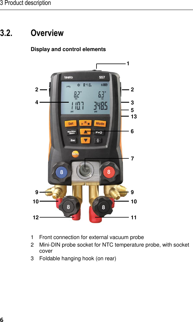
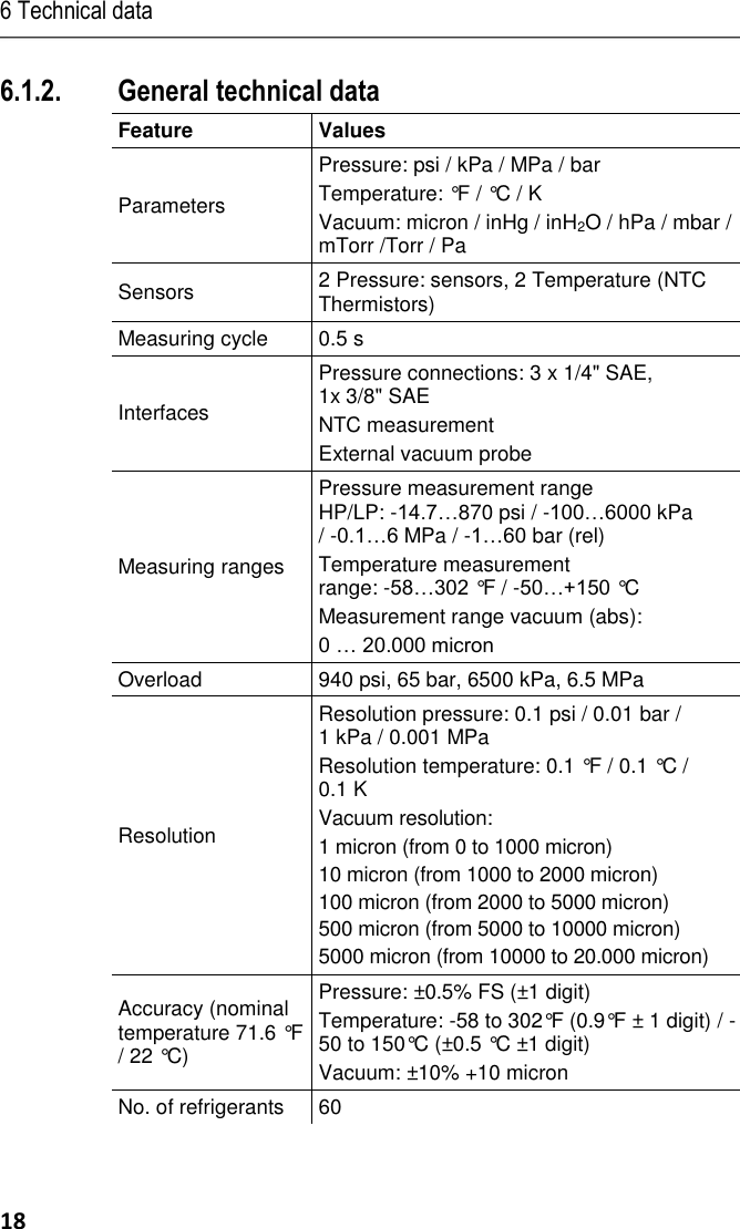
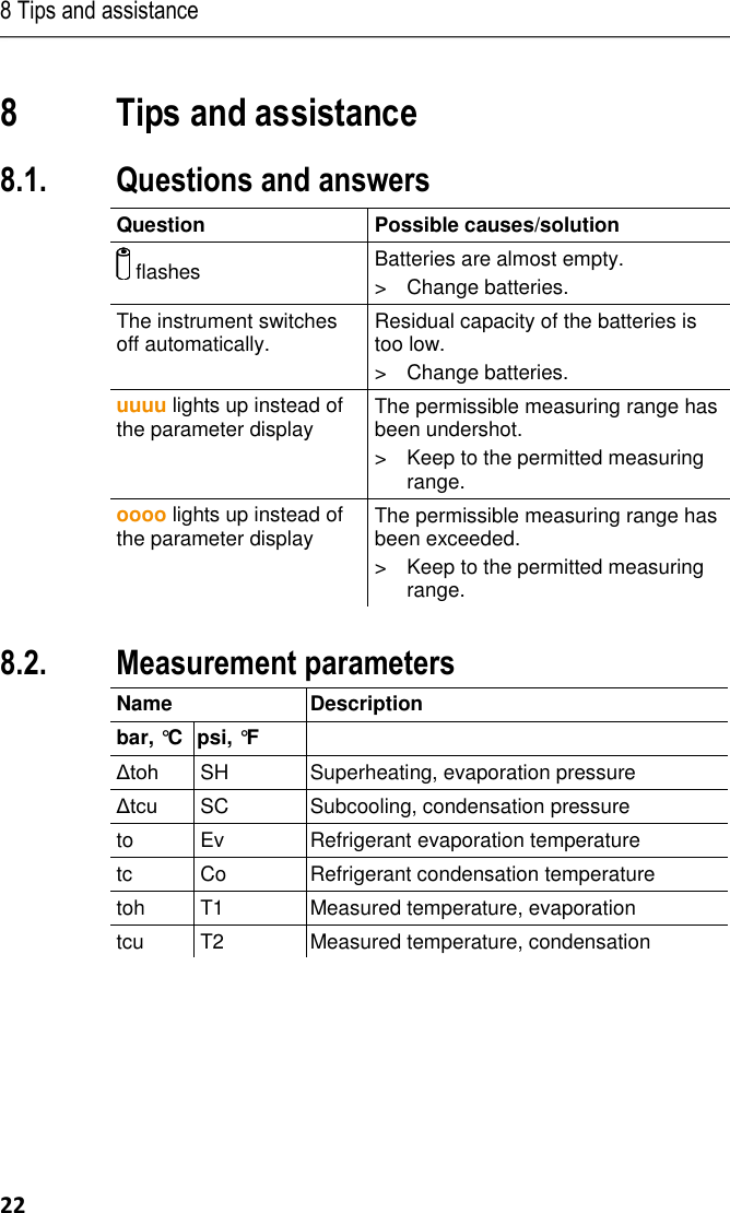
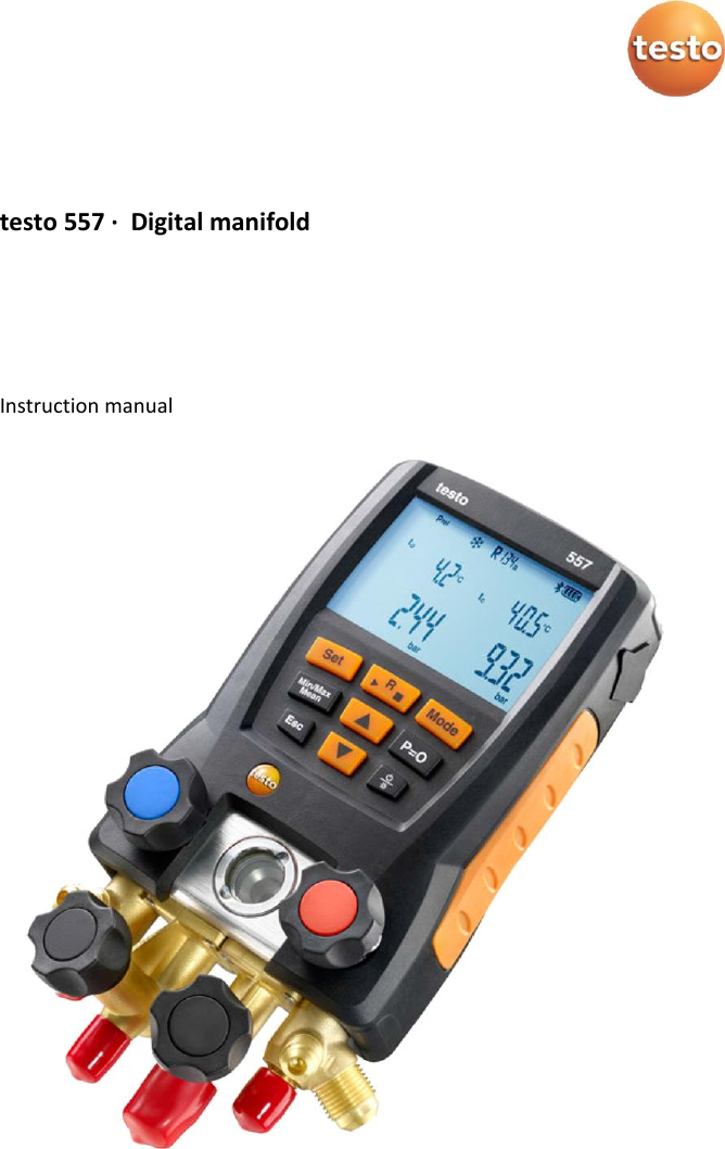
![3 Product description 7 4 Display. Instrument status icons: Icon Meaning Battery status Bluetooth® / / Select measuring mode 5 Battery compartment. The rechargeable batteries cannot be charged inside the instrument! 6 Control keys: Key Function [Set] Set units [R, ►, ■] Select refrigerant / Start-Stop leak test [Mode] Switch between measuring modes [Min/Max/Mean] Display min, max, mean values [▲] Up-key: Scroll through menu. [P=0] Pressure zeroing Esc Switches to the measurement/home view. [▼] Down-key: Scroll through menu. [ / ] Switching the instrument on/off Switching display ilumination on/off. 7 Sight glass for refrigerant flow. 8 4 x valve stem shutoff 94 x hose holders for refrigerant hoses 102 x Connection 1/4" SAE, brass. High pressure, for refrigerant hoses with quick release screw fitting, passage for valve actuator lockable. 11Connection 3/8" SAE, brass, for vacuum pump 12Connection 1/4" SAE, brass, for e.g. refrigerant cylinders 13 Mini-USB connection for firmware update, inside the battery compartment.](https://usermanual.wiki/testo-Instruments/05601557/User-Guide-2634714-Page-7.png)
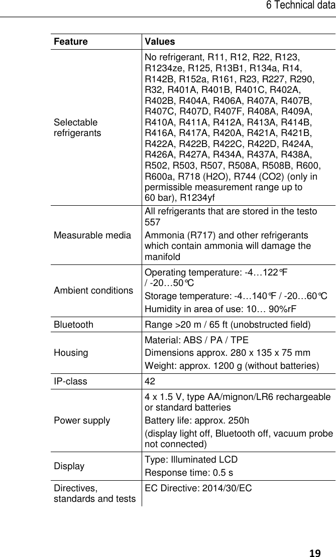
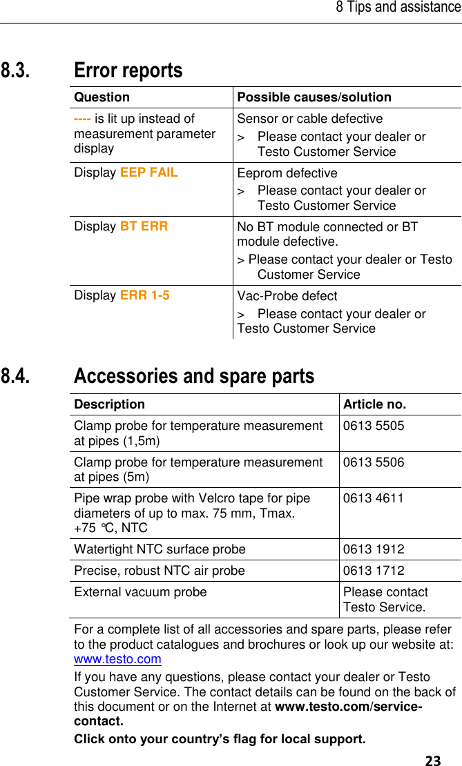
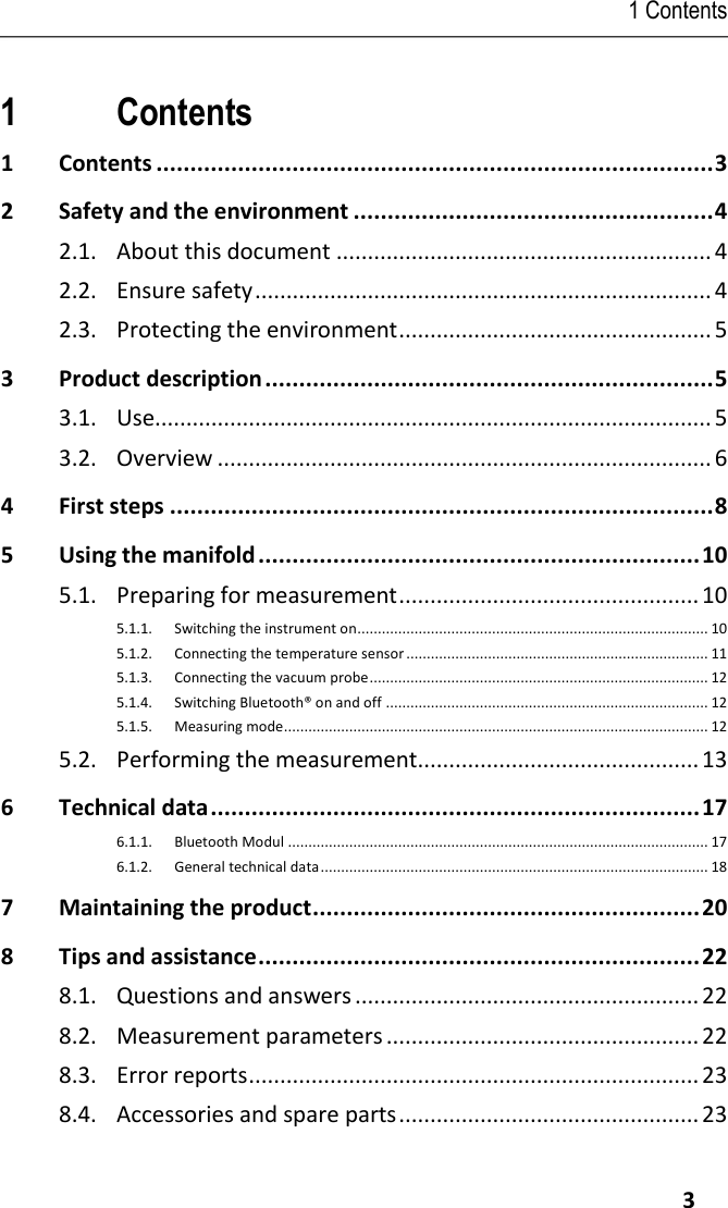
![4 First steps 8 : 24 /TD/--- Seitenwec hsel --- @ 0\mod_11737 74430601_0.d oc @ 281 Pos: 26 /TD/Üb erschriften/5. Erst e Schritte @ 0 \mod_117377 4895039_79.doc x @ 319 @ 1 @ 1 4 First steps Pos: 27 /TD/Erst e Schritte/testo 5571 @ 17\m od_14265010680 54_79.docx @ 211821 @ 555 5 @ 1 Inserting batteries/rechargeable batteries 1. Fold out the hanging hook and open the battery compartment by squeezing the clip lock. 2.Insert batteries (included in delivery) or rechargeable batteries (4x 1.5 V, type AA/Mignon/LR6) in the battery compartment. Observe the polarity! 3.Close the battery compartment. - After inserting the batteries, the instrument switches on automatically and goes into the settings menu. When not in use for long period: Remove batteries / rechargeable batteries. Units / Parameter selection 1. Press [Set] to confirm or change unit parameter settings 2. Press [▲] or [▼] to change the units / parameters. - The settings will be accepted once the last selection has been made. Key Functions Description [▲] or [▼] Change parameters and select units [Set] Confirm units / parameters Selectable parameters Description °C, °F Temperature unit bar, kPa, MPa, psi Unit for pressure. Pabs, Prel or psig Switch between absolute and relative pressure display micron, inHg, Pa, hPa, mTorr,Torr, inH2O, mbar Unit for vacuum pressure. / / Select measuring mode: heat pump / cooling / or Auto](https://usermanual.wiki/testo-Instruments/05601557/User-Guide-2634714-Page-8.png)
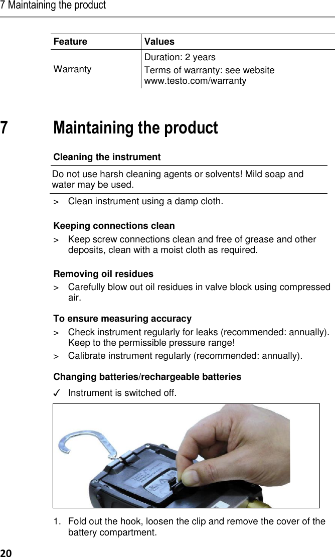
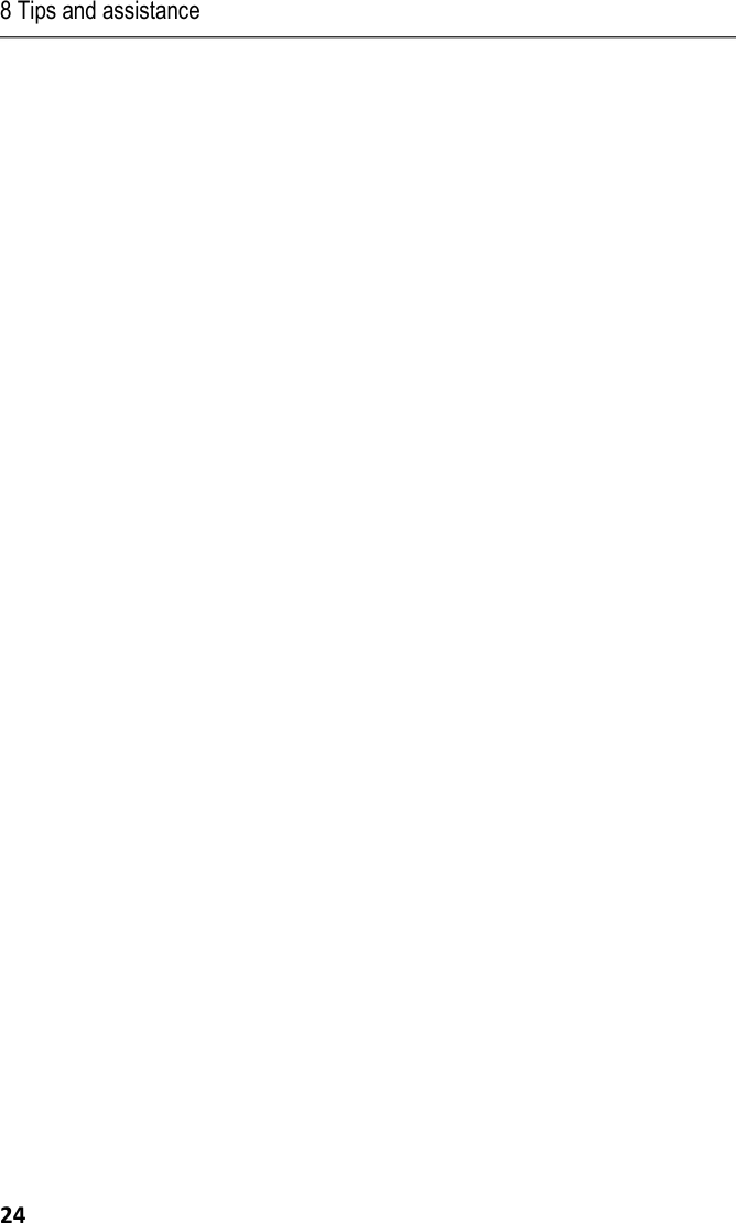
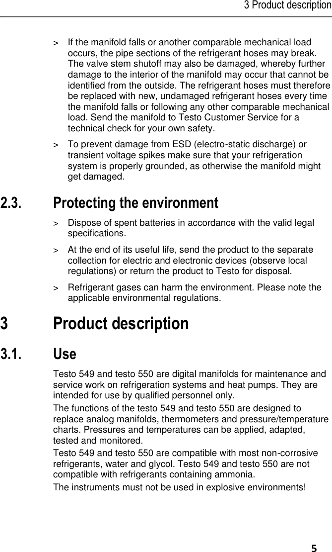
![5 Using the manifold 10 5 Using the manifold Pos: 29 /TD/Prod ukt verwenden/te sto 557/Anschli eßen, nullen, ei nstellen @ 7 \mod_128940 2475839_79. docx @ 73068 @ 23553555555 @ 1 5.1. Preparing for measurement 5.1.1. Switching the instrument on > Press [ / ]. Zero the pressure sensors before every measurement. ✓ All connections must be at ambient pressure. > Press [P=0] key for 3 seconds to execute zeroing. Connecting the refrigerant hoses Before each measurement check whether the refrigerant hoses are in flawless condition. ✓ Make sure the valve stem shutoffs are closed. 1.Connect the refrigerant hoses to the low-pressure side (blue) and high-pressure side (red). 2.Connect the refrigerant hoses to the AC/R system. WARNING Dropping this instrument or any other comparable mechanical shock can damage the refrigerant pipes and hoses. The valve actuators may also suffer damage, which in turn could result in further damage inside the instrument and may not be detectable from outside. > For your own safety you should return the manifold to the Testo Service Department for technical inspection. > You should therefore always replace the refrigerant hoses with new ones after an accidental drop has occurred or after any visible wear and tear. Choosing the refrigerant 1.Press [R, ►, ■]. - It activates the refrigerant menu and the currently selected refrigerant flashes. 2.Setting the refrigerant:](https://usermanual.wiki/testo-Instruments/05601557/User-Guide-2634714-Page-10.png)
![5 Using the manifold 11 Key functions Description [▲] or [▼] Selectng another refrigerant [R, ►, ■] Confirm the selection and exit the refrigerant menu Available refrigerants Representation Description R... Refrigerant number of refrigerant acc. to ISO 817 --- no refrigerant selected. Example: Setting refrigerant R401B 1.Press [R, ►, ■] to activate refrigerant menu. 2. Press [▲] or [▼] several times, until R401B flashes. 3.Press [R, ►, ■] to confirm the setting. Exiting the refrigerant selection > Press [R, ►, ■] or automatically after 30 s, if no other key has been pressed. 5.1.2. Connecting the temperature sensor Surface temperature sensor At least one NTC temperature probe must be connected to measure the pipe temperature, for automatic calculation of superheating and subcooling. Deactivating the surface compensation factor for insertion and air temperature sensor A surface compensation factor has been set in the measuring instrument to improve the measuring accuracy of surface temperature readings. If the manifold is used in combination with insertion or air temperature probe (optional), this factor must be deactivated: 1. Press [Set] repeatedly until Tfac is displayed. 2. Press [▲] or [▼] to set Tfac to Off. 3. Press [Set] to continue through the settings menu until the measurement/home view is displayed. - Tfac is shown on the display if Tfac is disabled.](https://usermanual.wiki/testo-Instruments/05601557/User-Guide-2634714-Page-11.png)
![5 Using the manifold 12 Pos: 30 /TD/Prod ukt verwenden/te sto 557/Vaku umsonde ansc hließen @ 16\ mod_142105 7560179_79.doc x @ 206127 @ 3 @ 1 5.1.3. Connecting the vacuum probe > Open the front cover of the connector and connect up the vacuum probe. Pos: 31 /TD/Prod ukt verwenden/te sto 557/Bluet ooth Überschrift 557 @ 16\ mod_1421058427 681_79.doc x @ 206167 @ 3 @ 1 5.1.4. Switching Bluetooth® on and off Pos: 32 /TD/Prod ukt verwenden/te sto 557/Bluet ooth ein-aussc halten @ 16\ mod_1418732 441244_79.docx @ 205497 @ @ 1 In order to to establish a connection via Bluetooth, on an Android or iOS device, the Testo App Refrigeration must be already installed. You can get the App for iOS instruments in the App Store or for Android instruments in the Play Store. Information about compatibility can be found in the relevant app store. 1. To turn on the Bluetooth press [▲] and [▼] simultaneously and hold down for 3 seconds. - Once the Bluetooth icon is shown on the display, Bluetooth is switched on.Display Description flashes There is no Bluetooth connection, or a potential connection is being searched for. is permanently displayed There is a Bluetooth connection. is not displayed Bluetooth is disabled. 2. To turn off the Bluetooth press [▲] and [▼] simultaneously and hold down for 3 seconds. - Once the Bluetooth icon is no longer shown on the display, Bluetooth is switched off.Pos: 33 /TD/Prod ukt verwenden/te sto 557/Mess modus testo 55 7 @ 7\mod_1 28940335025 0_79.docx @ 73 134 @ 3 @ 1 5.1.5. Measuring mode Display Mode Function Refrigeration system Normal function of the digital manifold Heat pump Normal function of the digital manifold](https://usermanual.wiki/testo-Instruments/05601557/User-Guide-2634714-Page-12.png)
![5 Using the manifold 14 condensation temperature Co/tc are displayed after evaporation and condensation are complete. Zeotropes (refrigerants blends mix together) can separate from each other, unlike azeotropes which mix together to become one. Zeoptropes often blend refrigerants with different boiling points (saturation temps), where one will change from liquid to vapor before the other as they go through the evaporator. The glide is the difference between the lowest boiling point and the highest boiling point. If they are 3 degrees apart, for example, the blend has a 3 degree glide.. The display illumination will flash if: • The critical pressure of the refrigerant is within 15 psi (1 bar) of the highest pressure (and temperature) where the refrigerant can still condense. • The maximum. permissible pressure of 870 psi (60 bar) is exceeded. Key functions > Press [▲] or [▼] to change the reading in the display. Possible display combinations: Refrigerant evaporation temperature Ev/to (°F/°C) Evaporation pressure (psi/bar) Refrigerant condensation temperature Co/tc (°F/°C) Condensation pressure (psi/bar) Measured temperature T1/toh (°F/°C) Evaporation pressure (psi/bar) Measured temperature T2/tcu (°F/°C) Condensation pressure (psi/bar) Superheating SH/Δtoh (°F/°C) Evaporation pressure (psi/bar) Subcooling SC/Δtcu (°F/°C) Condensation pressure (psi/bar)](https://usermanual.wiki/testo-Instruments/05601557/User-Guide-2634714-Page-14.png)
![5 Using the manifold 15 With both NTC temperature probes connected, Δt is also shown. > Press [Mean/Min/Max]: to display min. / max. readings and mean values. Leak test / pressure drop test Systems can be tested for tightness with the temperature-compensated leak test. The system pressure and the ambient temperature are measured over a defined period of time, typically with an inert gas such as Nitrogen. A temperature probe can be connected that measures the ambient temperature. : Optional air temperature probe, part. no. 0613 1712) is recommended. Measurement data of the temperature-compensated differential pressure and temperature, from start to the end of the test, is displayed. It is possible to perform a leak test without connecting a temperature probe. 1.Press [Mode] ΔP is displayed. 2.Start the leak test: Press [R, ►, ■]. ΔP is now flashing and hh:mm timer is on. 3.End the leak test: Press [R, ►, ■]. ΔP stops flashing and hh:mm timer stops. - Result is displayed. Note: Leak test time duration and ΔP value 4. Confirm the message: Press [Mode] to exit leak mode. Changeable - Evaporation Temperature (Ev) - Measured Temperature (T1) - Superheating (SH) Changeable - Condensation Temperature (Co) - Measured Temperature (T2) - Subcooling (SC) Condensation pressure Evaporation pressure](https://usermanual.wiki/testo-Instruments/05601557/User-Guide-2634714-Page-15.png)
![5 Using the manifold 16 Vacuum measurement ✓ The vacuum probe is plugged into the front connection of the manifold and connected to the system. 1. Press [Mode] the vacuum mode is displayed. If ambient pressure is applied to the vacuum probe, then oooo is shown on the display. 2. Start the vacuum pump. - Once the measuring range 0 to 20,000 microns is reached, the current vacuum value is shown on the instrument display. The instrument also displays the current ambient temperature, the water evaporation temperature, which corresponds to the vacuum reading, and the delta between these two temperatures. 3. To leave vacuum mode, remove the vacuum probe from the testo 557 or switch to the standard measurement view using the [Mode] button. Differential pressure start compared to actual Measured pressure beginning of test Duration of test Actual measured pressure](https://usermanual.wiki/testo-Instruments/05601557/User-Guide-2634714-Page-16.png)