testo Instruments 05601557 Digital manifold User Manual
testo Instruments (Shenzhen) Co., Ltd Digital manifold
user manual
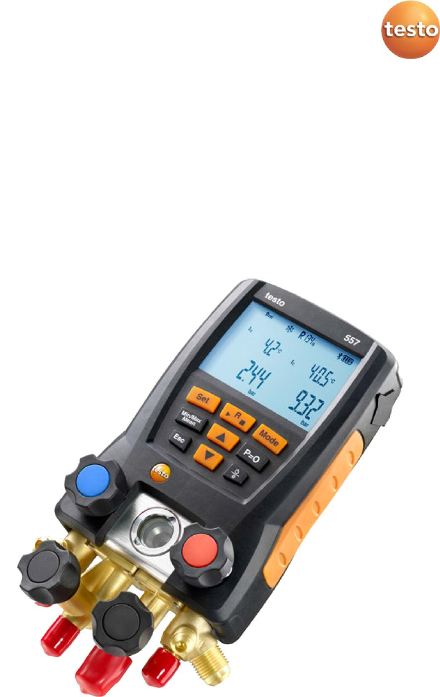
testo 557 · Digital manifold
Instruction manual

2

1 Contents
3
Pos: 1 /TD/Übersc hriften/1. Inhalt @ 0\mod_ 1177587817070 _79.docx @ 1 243 @ 1 @ 1
1 Contents
1 Contents .................................................................................. 3
2 Safety and the environment ..................................................... 4
2.1. About this document ............................................................ 4
2.2. Ensure safety ......................................................................... 4
2.3. Protecting the environment .................................................. 5
3 Product description .................................................................. 5
3.1. Use......................................................................................... 5
3.2. Overview ............................................................................... 6
4 First steps ................................................................................ 8
5 Using the manifold ................................................................. 10
5.1. Preparing for measurement ................................................ 10
5.1.1. Switching the instrument on...................................................................................... 10
5.1.2. Connecting the temperature sensor .......................................................................... 11
5.1.3. Connecting the vacuum probe ................................................................................... 12
5.1.4. Switching Bluetooth® on and off ............................................................................... 12
5.1.5. Measuring mode........................................................................................................ 12
5.2. Performing the measurement............................................. 13
6 Technical data ........................................................................ 17
6.1.1. Bluetooth Modul ....................................................................................................... 17
6.1.2. General technical data ............................................................................................... 18
7 Maintaining the product ......................................................... 20
8 Tips and assistance ................................................................. 22
8.1. Questions and answers ....................................................... 22
8.2. Measurement parameters .................................................. 22
8.3. Error reports ........................................................................ 23
8.4. Accessories and spare parts ................................................ 23
Pos: 2 /TD/--- Seiten wechsel --- @ 0\mod _1173774430601_ 0.docx @ 283 @ @ 1
2 Safety and the environment
4
Pos: 3 /TD/Übersc hriften/2. Sich erheit und Umwelt @ 0\mod_ 11737747193 51_79.docx @ 2 92 @ 1 @ 1
2 Safety and the environment
Pos: 4 /TD/Übersc hriften/2.1 Zu di esem Dokum ent @ 0\mod _1173775252 351_79.docx @ 3 46 @ 2 @ 1
2.1. About this document
Pos: 5 /TD/Sich erheit und Umwelt/Z u diesem Do kument/Ver wendung/Verwend ung (Standard) @ 0\mod_1 17377506855 4_79.docx @ 337 @ 5 @ 1
Use
> Please read this documentation carefully and familiarize
yourself with the product before putting it to use. Pay particular
attention to the safety instructions and warning advice in order
to prevent injuries and damage to the product.
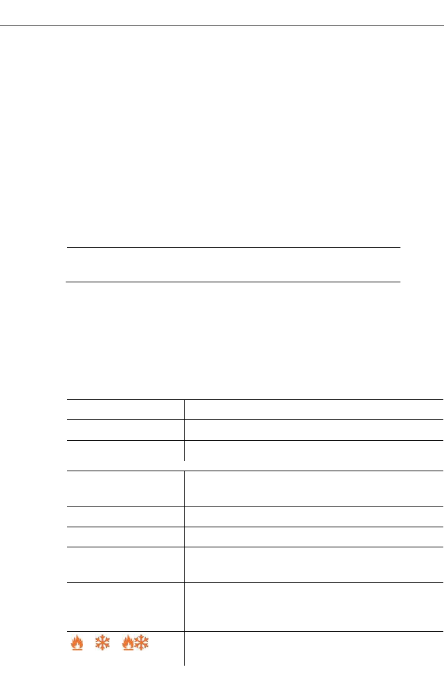
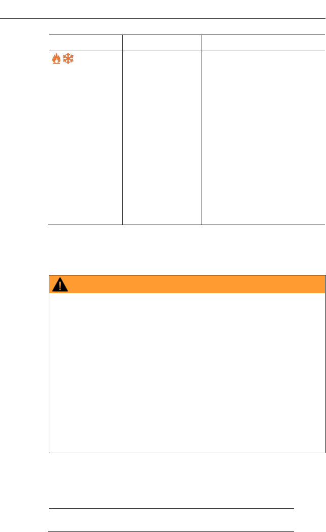
Pos: 6 /TD/Sich erheit und Umwelt/Z u diesem Do kument/Symb ole und Schreib konventionen/ Symbole und Schr eibkon v. [Standard_groß] @ 0\mod_1174 982140622_7 9.docx @ 515 @ 5 @ 1
Symbols and writing standards
Representation
Explanation
Warning advice, risk level according to the
signal word:
Warning! Serious physical injury may occur.
Caution! Slight physical injury or damage to
the equipment may occur.
> Implement the specified precautionary
measures.
Menu
Elements of the instrument, the instrument
display or the program interface.
[OK]
Control keys of the instrument or buttons of
the program interface.
Pos: 7 /TD/Übersc hriften/2.2 Sic herheit gewährl eisten @ 0\m od_11737807839 60_79.docx @ 366 @ 2 @ 1
2.2. Ensure safety
Pos: 8 /TD/Sich erheit und Umwelt/ Sicherheit ge währleisten/G erät bei Beschä digungen nicht in Betrieb neh men @ 0\mod_ 11869859453 75_79.docx @ 2252 @ @ 1
> Do not operate the instrument if there are signs of damage at
the housing, mains unit or hoses.
Pos: 9 /TD/Sich erheit und Umwelt/ Sicherheit ge währleisten/K eine Messung a n spannungsführ enden Teilen @ 0\mod_117 5692564164_ 79.docx @ 592 @ @ 1
Pos: 10 /TD/Sic herheit und Um welt/Sicherheit g ewährleisten/Nic ht mit Lösung smitteln lagern @ 0\mod_1 175692375179_ 79.docx @ 583 @ @ 1
> Do not store the product together with solvents. Do not use any
desiccants.
Pos: 11 /TD/Sic herheit und Um welt/Sicherheit g ewährleisten/N ur beschriebene Wartungsarb eiten durchführe n @ 0\mod _1175692705195 _79.docx @ 60 1 @ @ 1
> Carry out only the maintenance and repair work on this
instrument that is described in the documentation.
Pos: 12 /TD/ Sicherheit un d Umwelt/Sicherh eit gewährleiste n/vor Ort gültige Sicherheitsbes timmungen beachten @ 0\ mod_118699 7107328_79.doc x @ 2298 @ @ 1
> Dangers may also arise from the refrigeration systems being
measured or the measuring environment: Note the safety
regulations valid in your area when performing the
measurements.

3 Product description
5
Pos: 13 /TD/Sic herheit und Um welt/Sicherheit g ewährleisten/tes to 550/Mechanis che Belastu ng testo 550 @ 4\mod_12 52656121693_79. docx @ 49837 @ @ 1
> If the manifold falls or another comparable mechanical load
occurs, the pipe sections of the refrigerant hoses may break.
The valve stem shutoff may also be damaged, whereby further
damage to the interior of the manifold may occur that cannot be
identified from the outside. The refrigerant hoses must therefore
be replaced with new, undamaged refrigerant hoses every time
the manifold falls or following any other comparable mechanical
load. Send the manifold to Testo Customer Service for a
technical check for your own safety.
Pos: 14 /TD/Sic herheit und U mwelt/Sicherheit g ewährleisten/tes to 550/Ele ktrostatische Auflad ung testo 550 @ 6\mod_ 12767644280 65_79.docx @ 626 73 @ @ 1
> To prevent damage from ESD (electro-static discharge) or
transient voltage spikes make sure that your refrigeration
system is properly grounded, as otherwise the manifold might
get damaged.
Pos: 15 /TD/Üb erschriften/2.3 U mwelt schütze n @ 0\mod_1 17378084364 5_79.docx @ 37 5 @ 2 @ 1
2.3. Protecting the environment
Pos: 16.1 /TD/Sich erheit und U mwelt/Umwelt sc hützen/Akkus/B atterien ents orgen @ 0\mo d_117569363 7007_79.docx @ 619 @ @ 1
> Dispose of spent batteries in accordance with the valid legal
specifications.
Pos: 16.2 /TD/Sich erheit und U mwelt/Umwelt sc hützen/Produ kt entsorgen @ 0\mod_1173 780307072_79. docx @ 357 @ @ 1
> At the end of its useful life, send the product to the separate
collection for electric and electronic devices (observe local
regulations) or return the product to Testo for disposal.
Pos: 17 /TD/Sic herheit und Um welt/Umwelt sch ützen/testo 550/ Kältemittel können schade n testo 550 @ 4\ mod_125265 6710421_79.doc x @ 49869 @ @ 1
> Refrigerant gases can harm the environment. Please note the
applicable environmental regulations.
Pos: 18 /TD/Üb erschriften/3. Leist ungsbeschreib ung @ 0\m od_1173774791 554_79.docx @ 301 @ 1 @ 1
3 Product description
Pos: 19 /TD/Üb erschriften/3.1 Ver wendung @ 0\mod_11762 11016437_79.d ocx @ 695 @ 2 @ 1
3.1. Use
Pos: 20 /TD/Leist ungsbeschreib ung/Verwendu ng/testo 5xxtest o 557 @ 7\m od_12893928 71218_79.doc x @ 72935 @ @ 1
Testo 549 and testo 550 are digital manifolds for maintenance and
service work on refrigeration systems and heat pumps. They are
intended for use by qualified personnel only.
The functions of the testo 549 and testo 550 are designed to
replace analog manifolds, thermometers and pressure/temperature
charts. Pressures and temperatures can be applied, adapted,
tested and monitored.
Testo 549 and testo 550 are compatible with most non-corrosive
refrigerants, water and glycol. Testo 549 and testo 550 are not
compatible with refrigerants containing ammonia.
The instruments must not be used in explosive environments!
3 Product description
6
Pos: 21 /TD/Üb erschriften/3.2 T echnische Dat en @ 0\mod_117 6211088437_ 79.docx @ 7 04 @ 2 @ 1
Pos: 23 /TD/Üb erschriften/4. Prod uktbeschreibu ng @ 0\mod_ 11737748466 79_79.docx @ 3 10 @ 1 @ 1
Pos: 24 /TD/Üb erschriften/4.1 Ü bersicht @ 0\m od_117637994 6003_79.docx @ 733 @ 2 @ 1
3.2. Overview
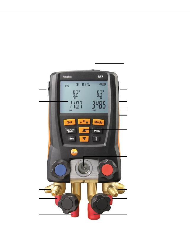
Pos: 25 /TD/Prod uktbeschreibung/Ü bersicht/test o 5571 @ 17 \mod_14265006 85437_79.doc x @ 211786 @ 5 @ 1
Display and control elements
1Front connection for external vacuum probe
2 Mini-DIN probe socket for NTC temperature probe, with socket
cover
3 Foldable hanging hook (on rear)
1
2
2
3
4
5
6
7
8
8
8
8
9
9
10
10
11
12
13
3 Product description
7
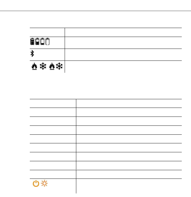
4 Display. Instrument status icons:
Icon
Meaning
Battery status
Bluetooth®
/ /
Select measuring mode
5 Battery compartment. The rechargeable batteries cannot be
charged inside the instrument!
6 Control keys:
Key
Function
[Set]
Set units
[R, ►, ■]
Select refrigerant / Start-Stop leak test
[Mode]
Switch between measuring modes
[Min/Max/Mean]
Display min, max, mean values
[▲]
Up-key: Scroll through menu.
[P=0]
Pressure zeroing
Esc
Switches to the measurement/home view.
[▼]
Down-key: Scroll through menu.
[ / ]
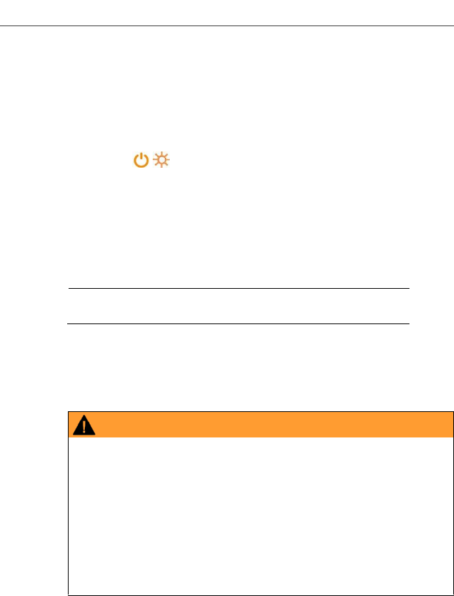
Switching the instrument on/off
Switching display ilumination on/off.
7 Sight glass for refrigerant flow.
8 4 x valve stem shutoff
94 x hose holders for refrigerant hoses
102 x Connection 1/4" SAE, brass.
High pressure, for refrigerant hoses with quick release screw
fitting, passage for valve actuator lockable.
11Connection 3/8" SAE, brass, for vacuum pump
12Connection 1/4" SAE, brass, for e.g. refrigerant cylinders
13 Mini-USB connection for firmware update, inside the battery
compartment.
4 First steps
8
: 24 /TD/--- Seitenwec hsel --- @ 0\mod_11737 74430601_0.d oc @ 281
Pos: 26 /TD/Üb erschriften/5. Erst e Schritte @ 0 \mod_117377 4895039_79.doc x @ 319 @ 1 @ 1
4 First steps
Pos: 27 /TD/Erst e Schritte/testo 5571 @ 17\m od_14265010680 54_79.docx @ 211821 @ 555 5 @ 1
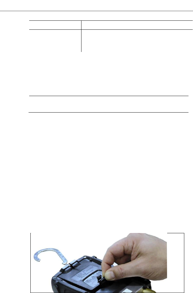
Inserting batteries/rechargeable batteries
1. Fold out the hanging hook and open the battery compartment
by squeezing the clip lock.
2.Insert batteries (included in delivery) or rechargeable batteries
(4x 1.5 V, type AA/Mignon/LR6) in the battery compartment.
Observe the polarity!
3.Close the battery compartment.
- After inserting the batteries, the instrument switches on
automatically and goes into the settings menu.
When not in use for long period: Remove batteries /
rechargeable batteries.
Units / Parameter selection
1. Press [Set] to confirm or change unit parameter settings
2. Press [▲] or [▼] to change the units / parameters.
- The settings will be accepted once the last selection has been
made.
Key Functions
Description
[▲] or [▼]
Change parameters and select units
[Set]
Confirm units / parameters
Selectable
parameters
Description
°C, °F
Temperature unit
bar, kPa, MPa, psi
Unit for pressure.
Pabs, Prel or psig
Switch between absolute and relative
pressure display
micron, inHg, Pa,
hPa, mTorr,Torr,
inH2O, mbar
Unit for vacuum pressure.
/ /
Select measuring mode: heat pump / cooling
/ or Auto
0
9
Selectable
parameters
Description
AUTO OFF
Activate or deactivate Automatic power-off.
Instrument switches off after 30 minutes if no
temperature probe is connected and there is
no pressure apart from ambient pressure
Tfac
Activate or deactivate surface temperature
compensation factor, icon is shown on the
display if the function is deactivated
- Settings will be applied following the final selection.
Operating the valve stem shutoffs
The digital manifold acts like a conventional two-way manifold with
regard to the refrigerant path: The passages are opened by
opening the valves. The adjacent pressure is measured with valves
closed as well as with them open.
> Open valve: Turn valve positioner counterclockwise.
> Close valve: Turn valve positioner clockwise.
WARNING
Over tightening the valve stem shutoffs may cause:
• Damage to the PTFE seal.
• Mechanical deformation of the valve piston leading to the
PTFE seal falling out.
• Damage to the thread of the threaded spindle and the valve
screw.
• valve knobs to brake.
Lightly tighten the valve knob. Do not use tools to tighten the valve
stem shutoffs.
Pos: 28 /TD/Üb erschriften/6. Prod ukt verwend en @ 0\mo d_1173774928554_ 79.docx @ 3 28 @ 1 @ 1
5 Using the manifold
10
5 Using the manifold
Pos: 29 /TD/Prod ukt verwenden/te sto 557/Anschli eßen, nullen, ei nstellen @ 7 \mod_128940 2475839_79. docx @ 73068 @ 23553555555 @ 1
5.1. Preparing for measurement
5.1.1. Switching the instrument on
> Press [ / ].
Zero the pressure sensors before every measurement.
✓ All connections must be at ambient pressure.
> Press [P=0] key for 3 seconds to execute zeroing.
Connecting the refrigerant hoses
Before each measurement check whether the refrigerant
hoses are in flawless condition.
✓ Make sure the valve stem shutoffs are closed.
1.Connect the refrigerant hoses to the low-pressure side (blue)
and high-pressure side (red).
2.Connect the refrigerant hoses to the AC/R system.
WARNING
Dropping this instrument or any other comparable mechanical
shock can damage the refrigerant pipes and hoses. The valve
actuators may also suffer damage, which in turn could result in
further damage inside the instrument and may not be
detectable from outside.
> For your own safety you should return the manifold to the
Testo Service Department for technical inspection.
> You should therefore always replace the refrigerant hoses with
new ones after an accidental drop has occurred or after any
visible wear and tear.
Choosing the refrigerant
1.Press [R, ►, ■].
- It activates the refrigerant menu and the currently selected
refrigerant flashes.
2.Setting the refrigerant:

5 Using the manifold
11
Key functions
Description
[▲] or [▼]
Selectng another refrigerant
[R, ►, ■]
Confirm the selection and exit the refrigerant
menu
Available refrigerants
Representation
Description
R...
Refrigerant number of refrigerant acc. to
ISO 817
---
no refrigerant selected.
Example: Setting refrigerant R401B
1.Press [R, ►, ■] to activate refrigerant menu.
2. Press [▲] or [▼] several times, until R401B flashes.
3.Press [R, ►, ■] to confirm the setting.
Exiting the refrigerant selection
> Press [R, ►, ■] or automatically after 30 s, if no other key has
been pressed.
5.1.2. Connecting the temperature sensor
Surface temperature sensor
At least one NTC temperature probe must be connected to
measure the pipe temperature, for automatic calculation of
superheating and subcooling.
Deactivating the surface compensation factor for insertion and
air temperature sensor
A surface compensation factor has been set in the measuring
instrument to improve the measuring accuracy of surface
temperature readings.
If the manifold is used in combination with insertion or air
temperature probe (optional), this factor must be deactivated:
1. Press [Set] repeatedly until Tfac is displayed.
2. Press [▲] or [▼] to set Tfac to Off.
3. Press [Set] to continue through the settings menu until the
measurement/home view is displayed.
- Tfac is shown on the display if Tfac is disabled.
5 Using the manifold
12
Pos: 30 /TD/Prod ukt verwenden/te sto 557/Vaku umsonde ansc hließen @ 16\ mod_142105 7560179_79.doc x @ 206127 @ 3 @ 1
5.1.3. Connecting the vacuum probe
> Open the front cover of the connector and connect up the
vacuum probe.
Pos: 31 /TD/Prod ukt verwenden/te sto 557/Bluet ooth Überschrift 557 @ 16\ mod_1421058427 681_79.doc x @ 206167 @ 3 @ 1
5.1.4. Switching Bluetooth® on and off
Pos: 32 /TD/Prod ukt verwenden/te sto 557/Bluet ooth ein-aussc halten @ 16\ mod_1418732 441244_79.docx @ 205497 @ @ 1
In order to to establish a connection via Bluetooth, on an
Android or iOS device, the Testo App Refrigeration must be
already installed.
You can get the App for iOS instruments in the App Store
or for Android instruments in the Play Store.
Information about compatibility can be found in the relevant
app store.
1. To turn on the Bluetooth press [▲] and [▼] simultaneously and
hold down for 3 seconds.
- Once the Bluetooth icon is shown on the display, Bluetooth is
switched on.
Display
Description
flashes
There is no Bluetooth connection, or a
potential connection is being searched for.
is permanently
displayed
There is a Bluetooth connection.
is not displayed
Bluetooth is disabled.
2. To turn off the Bluetooth press [▲] and [▼] simultaneously and
hold down for 3 seconds.
- Once the Bluetooth icon is no longer shown on the display,
Bluetooth is switched off.
Pos: 33 /TD/Prod ukt verwenden/te sto 557/Mess modus testo 55 7 @ 7\mod_1 28940335025 0_79.docx @ 73 134 @ 3 @ 1
5.1.5. Measuring mode
Display
Mode
Function
Refrigeration
system
Normal function of the digital
manifold
Heat pump
Normal function of the digital
manifold
5 Using the manifold
13
Display
Mode
Function
Automatic mode
If the automatic mode is
activated, the testo 557
digital manifold automatically
changes the display of the
high and low pressure. This
automatic change occurs
when the pressure on the
low-pressure side is 1 bar (15
psi) higher than the pressure
on the high-pressure side.
During the change, Load (2
s) is shown in the display.
This mode is especially
suited to air conditioning
systems which cool and heat
(heat pumps).
Pos: 34 /TD/Prod ukt verwenden/te sto 557/M essung durchfü hren testo 5571 @ 17\mod_1 426501166387_ 79.docx @ 2118 56 @ 255555 @ 1
5.2. Performing the measurement
WARNING
Risk of injury caused by refrigerant that is at high pressure,
hot, cold, or poisonous!
> Wear safety goggles and protective gloves..
> Before pressurizing the measuring instrument: Always fasten
the measuring instrument at the hanging hook in order to
prevent it from falling (risk of breakage)
> Check if the refrigerant hoses are intact and connected
correctly before each measurement. Do not use a tool to
connect the hoses. Only tighten the hoses by hand (max.
torque 5.0 Nm/3.7 ft*lb).
> Do not exceed the permissible measuring range (0 to 870 psi /
0 to 60 bar). Pay particular attention with systems with
refrigerant R744, as these are often operated with higher
pressures.
Measuring
1.Connect and apply pressure to the manifold.
2.See readings.
Note: With refrigerants that have a temperature glide,
“Zeotropes” the evaporation temperature Ev/to and

5 Using the manifold
14
condensation temperature Co/tc are displayed after
evaporation and condensation are complete.
Zeotropes (refrigerants blends mix together) can separate
from each other, unlike azeotropes which mix together to
become one. Zeoptropes often blend refrigerants with
different boiling points (saturation temps), where one will
change from liquid to vapor before the other as they go
through the evaporator. The glide is the difference between
the lowest boiling point and the highest boiling point. If they
are 3 degrees apart, for example, the blend has a 3 degree
glide..
The display illumination will flash if:
• The critical pressure of the refrigerant is within 15 psi (1 bar)
of the highest pressure (and temperature) where the
refrigerant can still condense.
• The maximum. permissible pressure of 870 psi (60 bar) is
exceeded.
Key functions
> Press [▲] or [▼] to change the reading in the display.
Possible display combinations:
Refrigerant evaporation
temperature Ev/to (°F/°C)
Evaporation pressure
(psi/bar)
Refrigerant condensation
temperature Co/tc (°F/°C)
Condensation pressure
(psi/bar)
Measured temperature T1/toh
(°F/°C)
Evaporation pressure
(psi/bar)
Measured temperature T2/tcu
(°F/°C)
Condensation pressure
(psi/bar)
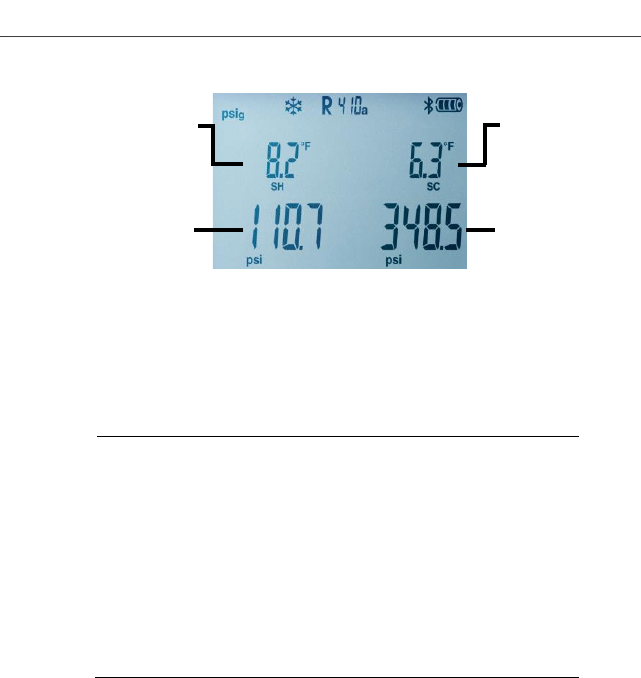
Superheating SH/Δtoh (°F/°C)
Evaporation pressure
(psi/bar)
Subcooling SC/Δtcu (°F/°C)
Condensation pressure
(psi/bar)
5 Using the manifold
15
With both NTC temperature probes connected, Δt is also shown.
> Press [Mean/Min/Max]: to display min. / max. readings and
mean values.
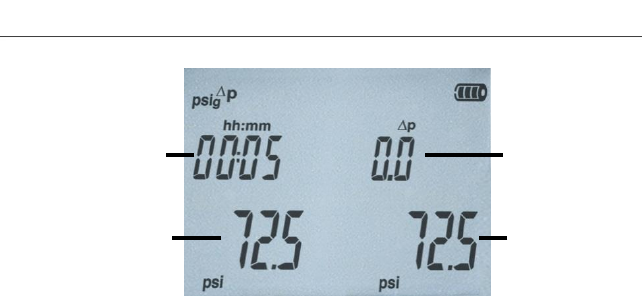
Leak test / pressure drop test
Systems can be tested for tightness with the temperature-
compensated leak test. The system pressure and the
ambient temperature are measured over a defined period of
time, typically with an inert gas such as Nitrogen. A
temperature probe can be connected that measures the
ambient temperature. : Optional air temperature probe,
part. no. 0613 1712) is recommended.
Measurement data of the temperature-compensated
differential pressure and temperature, from start to the end
of the test, is displayed. It is possible to perform a leak test
without connecting a temperature probe.
1.Press [Mode] ΔP is displayed.
2.Start the leak test: Press [R, ►, ■]. ΔP is now flashing and
hh:mm timer is on.
3.End the leak test: Press [R, ►, ■]. ΔP stops flashing and
hh:mm timer stops.
- Result is displayed. Note: Leak test time duration and ΔP value
4. Confirm the message: Press [Mode] to exit leak mode.
Changeable
- Evaporation
Temperature (Ev)
- Measured
Temperature (T1)
- Superheating (SH)
Changeable
- Condensation
Temperature (Co)
- Measured
Temperature (T2)
- Subcooling (SC)
Condensation
pressure
Evaporation
pressure
5 Using the manifold
16
Vacuum measurement
✓ The vacuum probe is plugged into the front connection of the
manifold and connected to the system.
1. Press [Mode] the vacuum mode is displayed.
If ambient pressure is applied to the vacuum probe, then oooo is
shown on the display.
2. Start the vacuum pump.
- Once the measuring range 0 to 20,000 microns is reached, the
current vacuum value is shown on the instrument display. The
instrument also displays the current ambient temperature, the
water evaporation temperature, which corresponds to the
vacuum reading, and the delta between these two
temperatures.
3. To leave vacuum mode, remove the vacuum probe from the
testo 557 or switch to the standard measurement view using the
[Mode] button.
Differential
pressure start
compared to
actual
Measured
pressure
beginning
of test
Duration
of test
Actual
measured
pressure

6 Technical data
17
6 Technical data
Pos: 22 /TD/Leist ungsbeschreib ung/Technische D aten/testo 557 1 @ 17\mo d_142650029 2878_79.docx @ 211611 @ 3 3 @ 1
6.1.1. Bluetooth Modul
The Bluetooth® option may only be operated in countries in
which it is type approved.
Feature
Values
Bluetooth
Range >20 m (free field)
Bluetooth type
LSD Science & Technology Co., Ltd
L Series BLE Module (08 Mai 2013)
based on TI CC254X chip
Qualified Design ID
B016552
Bluetooth radio
class
Class 3
Bluetooth company
10274
European Union
Austria, Belgium, Bulgaria, Croatia, Cyprus, Czech Republic,
Denmark, Estonia, Finland, France, Germany, Greece, Hungary,
Ireland, Italy, Latvia, Lithuania, Luxembourg, Malta, Netherlands,
Poland, Portugal, Romania, Slovakia, Slovenia, Spain, Sweden,
United Kingdom.
EFTA countries
Island, Suisse, Norway, Lichtenstein.
Other countries
USA, Canada, Turkey, Hong Kong, Australia, New Zealand.
Information from the FCC (Federal Communications Commission)
This device complies with part 15 of the FCC Rules. Its
commissioning is subject to the two following conditions: (1) This
instrument must not cause any harmful interference and (2) this
instrument must be able to cope with interference, even if this has
undesirable effects on operation.
Changes
The FCC demands that the user be informed that any changes or
modifications to the instrument that are not explicitly approved by
Testo AG may void the user's right to use this instrument.

6 Technical data
18
6.1.2. General technical data
Feature
Values
Parameters
Pressure: psi / kPa / MPa / bar
Temperature: °F / °C / K
Vacuum: micron / inHg / inH2O / hPa / mbar /
mTorr /Torr / Pa
Sensors
2 Pressure: sensors, 2 Temperature (NTC
Thermistors)
Measuring cycle
0.5 s
Interfaces
Pressure connections: 3 x 1/4" SAE,
1x 3/8" SAE
NTC measurement
External vacuum probe
Measuring ranges
Pressure measurement range
HP/LP: -14.7…870 psi / -100…6000 kPa
/ -0.1…6 MPa / -1…60 bar (rel)
Temperature measurement
range: -58…302 °F / -50…+150 °C
Measurement range vacuum (abs):
0 … 20.000 micron
Overload
940 psi, 65 bar, 6500 kPa, 6.5 MPa
Resolution
Resolution pressure: 0.1 psi / 0.01 bar /
1 kPa / 0.001 MPa
Resolution temperature: 0.1 °F / 0.1 °C /
0.1 K
Vacuum resolution:
1 micron (from 0 to 1000 micron)
10 micron (from 1000 to 2000 micron)
100 micron (from 2000 to 5000 micron)
500 micron (from 5000 to 10000 micron)
5000 micron (from 10000 to 20.000 micron)
Accuracy (nominal
temperature 71.6 °F
/ 22 °C)
Pressure: ±0.5% FS (±1 digit)
Temperature: -58 to 302°F (0.9°F ± 1 digit) / -
50 to 150°C (±0.5 °C ±1 digit)
Vacuum: ±10% +10 micron
No. of refrigerants
60

6 Technical data
19
Feature
Values
Selectable
refrigerants
No refrigerant, R11, R12, R22, R123,
R1234ze, R125, R13B1, R134a, R14,
R142B, R152a, R161, R23, R227, R290,
R32, R401A, R401B, R401C, R402A,
R402B, R404A, R406A, R407A, R407B,
R407C, R407D, R407F, R408A, R409A,
R410A, R411A, R412A, R413A, R414B,
R416A, R417A, R420A, R421A, R421B,
R422A, R422B, R422C, R422D, R424A,
R426A, R427A, R434A, R437A, R438A,
R502, R503, R507, R508A, R508B, R600,
R600a, R718 (H2O), R744 (CO2) (only in
permissible measurement range up to
60 bar), R1234yf
Measurable media
All refrigerants that are stored in the testo
557
Ammonia (R717) and other refrigerants
which contain ammonia will damage the
manifold
Ambient conditions
Operating temperature: -4…122°F
/ -20…50°C
Storage temperature: -4…140°F / -20…60°C
Humidity in area of use: 10… 90%rF
Bluetooth
Range >20 m / 65 ft (unobstructed field)
Housing
Material: ABS / PA / TPE
Dimensions approx. 280 x 135 x 75 mm
Weight: approx. 1200 g (without batteries)
IP-class
42
Power supply
4 x 1.5 V, type AA/mignon/LR6 rechargeable
or standard batteries
Battery life: approx. 250h
(display light off, Bluetooth off, vacuum probe
not connected)
Display
Type: Illuminated LCD
Response time: 0.5 s
Directives,
standards and tests
EC Directive: 2014/30/EC
7 Maintaining the product
20
Feature
Values
Warranty
Duration: 2 years
Terms of warranty: see website
www.testo.com/warranty
Pos: 35 /TD/Üb erschriften/7. Prod ukt instand halt en @ 0\mo d_11737898313 62_79.docx @ 3 97 @ 1 @ 1
7 Maintaining the product
Pos: 36 /TD/Prod ukt instand halt en/Gerät reinig en 5571 @ 17\ mod_14265 01226500_79.d ocx @ 211891 @ 2 @ 1
Cleaning the instrument
Do not use harsh cleaning agents or solvents! Mild soap and
water may be used.
> Clean instrument using a damp cloth.
Pos: 37 /TD/Prod ukt instand halt en/testo 550/Ins tandhalten test o 550 @ 4\ mod_1253262226 679_79.doc x @ 50494 @ 555 55 @ 1
Keeping connections clean
> Keep screw connections clean and free of grease and other
deposits, clean with a moist cloth as required.
Removing oil residues
> Carefully blow out oil residues in valve block using compressed
air.
To ensure measuring accuracy
> Check instrument regularly for leaks (recommended: annually).
Keep to the permissible pressure range!
> Calibrate instrument regularly (recommended: annually).
Changing batteries/rechargeable batteries
✓ Instrument is switched off.
1.Fold out the hook, loosen the clip and remove the cover of the
battery compartment.
7 Maintaining the product
21
2.Remove discharged batteries/rechargeable batteries and insert
new batteries/rechargeable batteries (4x 1.5 V, type AA,
Mignon, LR6) in the battery compartment. Observe the polarity!
3. Set on and close cover of the battery compartment (clip must
engage).
4.Switch the instrument on.
Changing the valve or valve stem shutoff
DO NOT ATTEMPT to change the valve stems. Changing the valve
stem shutoff or valves themselves will void the warranty.
Send the measuring instrument to Testo Customer Service.
Cleaning the vacuum probe
Contaminants such as oil may impair the accuracy of the vacuum
sensor.
CAUTION
Carrying out cleaning with the probe connected may result in
damage to the probe!
> Remove the vacuum probe from the testo 557!
CAUTION
Damage to the sensor due to sharp objects!
> Do not insert any sharp objects into the probe!
1. Remove the vacuum probe from the testo 557.
2. Put a few drops of rubbing alcohol into the sensor opening.
3. Seal the opening by placing your finger on it and shake the
vacuum probe briefly.
4. Remove all the alcohol from the probe.
5. Repeat this process at least twice.
6. Leave the probe to dry for at least 1 hour. To dry the sensor
faster, you can connect the probe directly to a vacuum pump
and draw vacuum.
8 Tips and assistance
22
Pos: 38 /TD/Üb erschriften/8. Tip ps und Hilfe @ 0\mod_11737 89887985_79.d ocx @ 406 @ 1 @ 1
8 Tips and assistance
Pos: 39 /TD/Üb erschriften/8.1 Fr agen und Ant worten @ 0\ mod_11774020170 78_79.docx @ 1093 @ 2 @ 1
8.1. Questions and answers
Pos: 40 /TD/Tip ps und Hilfe/Frag en und Ant worten/testo 550/FA Q testo 550 @ 5\mod_126 5185945986_79.d ocx @ 5696 4 @ @ 1
Question
Possible causes/solution
flashes
Batteries are almost empty.
> Change batteries.
The instrument switches
off automatically.
Residual capacity of the batteries is
too low.
> Change batteries.
uuuu lights up instead of
the parameter display
The permissible measuring range has
been undershot.
> Keep to the permitted measuring
range.
oooo lights up instead of
the parameter display
The permissible measuring range has
been exceeded.
> Keep to the permitted measuring
range.
Pos: 41 /TD/Tip ps und Hilfe/Frag en und Ant worten/testo 550/Mes sgrößen testo 550 @ 5\ mod_126518610 4485_79.docx @ 56996 @ 2 @ 1
8.2. Measurement parameters
Name
Description
bar, °C
psi, °F
Δtoh
SH
Superheating, evaporation pressure
Δtcu
SC
Subcooling, condensation pressure
to
Ev
Refrigerant evaporation temperature
tc
Co
Refrigerant condensation temperature
toh
T1
Measured temperature, evaporation
tcu
T2
Measured temperature, condensation
Pos: 42 /TD/Tip ps und Hilfe/Fe hlermeldungen/Fe hlermeldung en testo 550 @ 5\mod_12641 66753739_79.do cx @ 56778 @ 2 @ 1

8 Tips and assistance
23
8.3. Error reports
Question
Possible causes/solution
---- is lit up instead of
measurement parameter
display
Sensor or cable defective
> Please contact your dealer or
Testo Customer Service
Display EEP FAIL
Eeprom defective
> Please contact your dealer or
Testo Customer Service
Display BT ERR
No BT module connected or BT
module defective.
> Please contact your dealer or Testo
Customer Service
Display ERR 1-5
Vac-Probe defect
> Please contact your dealer or
Testo Customer Service
Pos: 43 /TD/Tip ps und Hilfe/Ser vice-Informati onen (für PoD)/ Kontaktdaten allg emein @ 3\m od_12222642 20446_79.doc x @ 23423 @ @ 1
Pos: 44 /TD/Üb erschriften/8.3 Z ubehör und Ers atzteile @ 0\ mod_1177402 058734_79.docx @ 1102 @ 2 @ 1
8.4. Accessories and spare parts
Pos: 45 /TD/Tip ps und Hilfe/Zu behör und Ersatz teile/Zubehör tes to 5571 @ 1 7\mod_14265 01312455_79. docx @ 21192 6 @ @ 1
Description
Article no.
Clamp probe for temperature measurement
at pipes (1,5m)
0613 5505
Clamp probe for temperature measurement
at pipes (5m)
0613 5506
Pipe wrap probe with Velcro tape for pipe
diameters of up to max. 75 mm, Tmax.
+75 °C, NTC
0613 4611
Watertight NTC surface probe
0613 1912
Precise, robust NTC air probe
0613 1712
External vacuum probe
Please contact
Testo Service.
For a complete list of all accessories and spare parts, please refer
to the product catalogues and brochures or look up our website at:
www.testo.com
If you have any questions, please contact your dealer or Testo
Customer Service. The contact details can be found on the back of
this document or on the Internet at www.testo.com/service-
contact.
Click onto your country’s flag for local support.

8 Tips and assistance
24
=== Ende der List e für Textmar ke Inhalt ===

0970 5571 en-US 01 V01.11
Testo Inc.
40 White Lake Road
Sparta, N. J. 07871
Phone: +1 862 354 5001
Fax: +1 862 354 5020
Email: info@testo.com
www.testo.com
Headquarter
testo AG
Testo-Straße 1
79853 Lenzkirch
Germany
Tel.: +49 7653 681-0
Fax: +49 7653 681-7699
Email: info@testo.de
Internet: www.testo.de
FCC statements:
This device complies with part 15 of the FCC rules. Operation is subject to the
following two conditions: (1) this device may not cause harmful interference, and (2)
this device must accept any interference received, including interference that may
cause undesired operation.
NOTE: The manufacturer is not responsible for any radio or TV interference caused
by unauthorized modifications or changes to this equipment. Such modifications or
changes could void the user’s authority to operate the equipment.
NOTE: This equipment has been tested and found to comply with the limits for a
Class B digital device, pursuant to part 15 of the FCC Rules. These limits are designed
to provide reasonable protection against harmful interference in a residential
installation. This equipment generates uses and can radiate radio frequency energy
and, if not installed and used in accordance with the instructions, may cause harmful
interference to radio communications. However, there is no guarantee that
interference will not occur in a particular installation. If this equipment does cause
harmful interference to radio or television reception, which can be determined by
turning the equipment off and on, the user is encouraged to try to correct the
interference by one or more of the following measures:
‐ Reorient or relocate the receiving antenna.
‐ Increase the separation between the equipment and receiver.
‐Connect the equipment into an outlet on a circuit different from that to which the
receiver is connected.
‐Consult the dealer or an experienced radio/TV technician for help.
This device complies with Industry Canada license‐exempt RSS standard(s).
Operation is subject to the following two conditions:
this device may not cause interference, and
(2) this device must accept any interference, including interference that may cause
undesired operation of the device.
Cet appareil est conforme avec Industrie Canada RSS exemptes de licence standard(s).
Son fonctionnement est soumis aux deux conditions suivantes:
(1) cet appareil ne peut pas provoquer d'interférences, et
(2) cet appareil doit accepter toute interférence, y compris celles pouvant causer un
mauvais fonctionnement de l'appareil.
RF exposure information: The Maximum Permissible Exposure (MPE) level has been
calculated based on a distance of d=5mm between the device and the human body.
To maintain compliance with RF exposure requirement, use product that maintain a
5mm distance between the device and human body.