u blox Malmo 090103AP Wireless Communication System Module User Manual Bluetooth Web Enabler
u-blox Malmo AB Wireless Communication System Module Bluetooth Web Enabler
Contents
- 1. Integration Manual Host
- 2. Users Manual Host
- 3. Integration Manual I
- 4. Integration Manual II
Users Manual Host

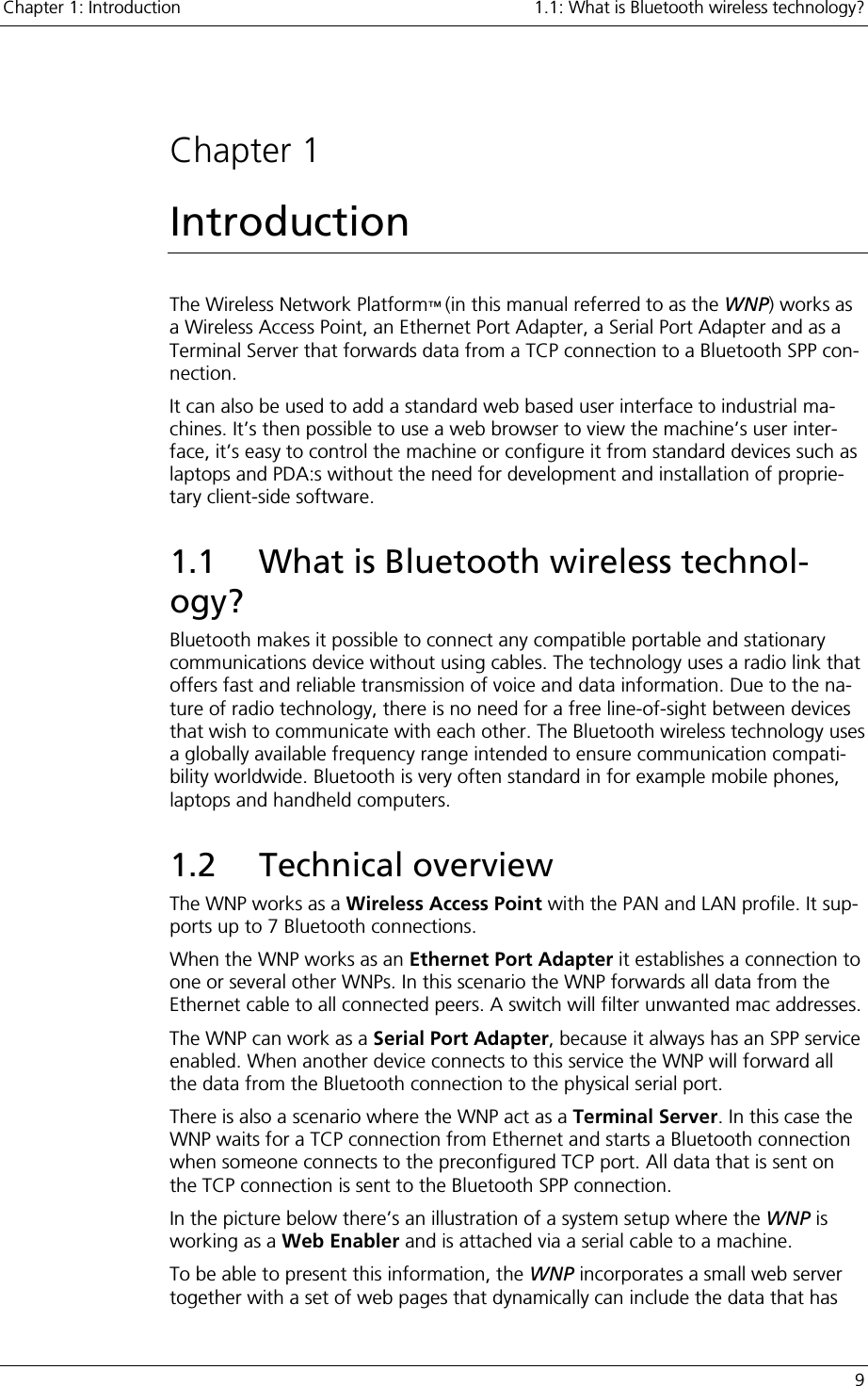
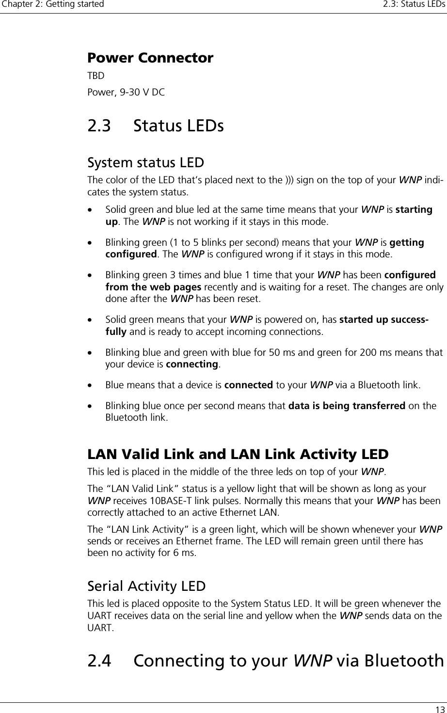
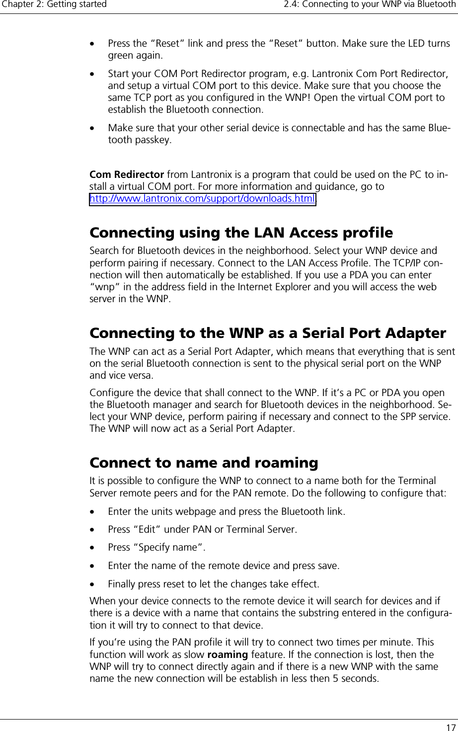
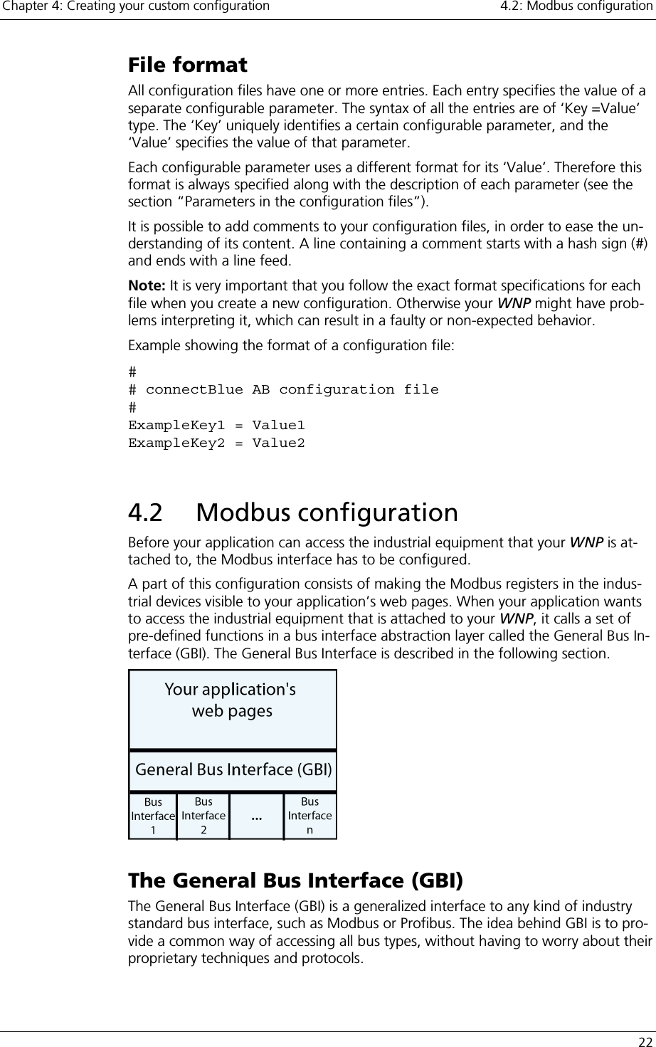
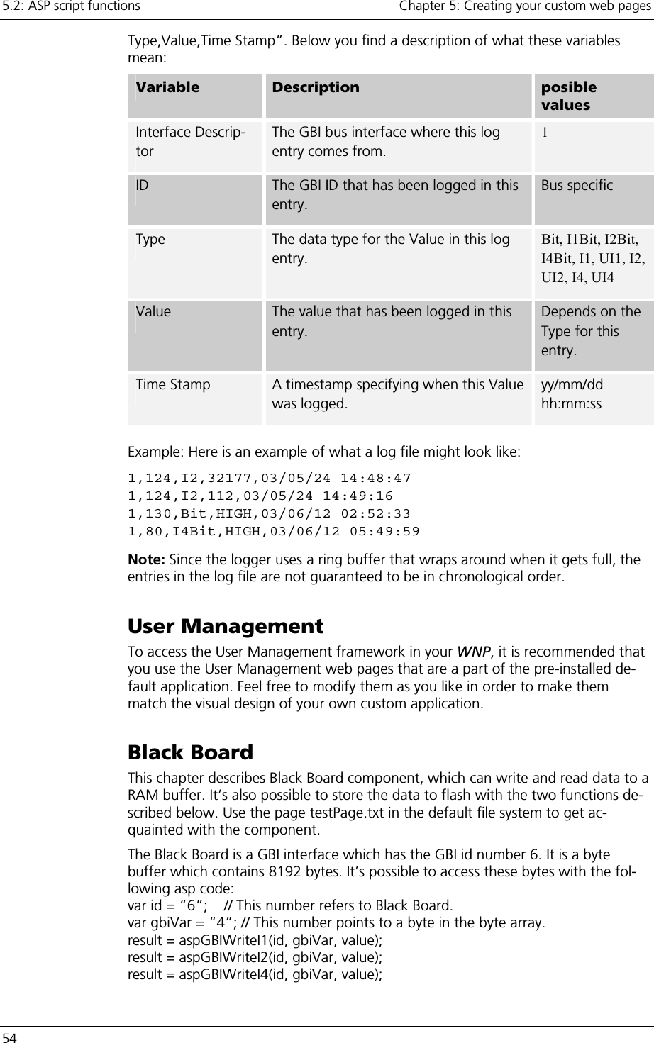
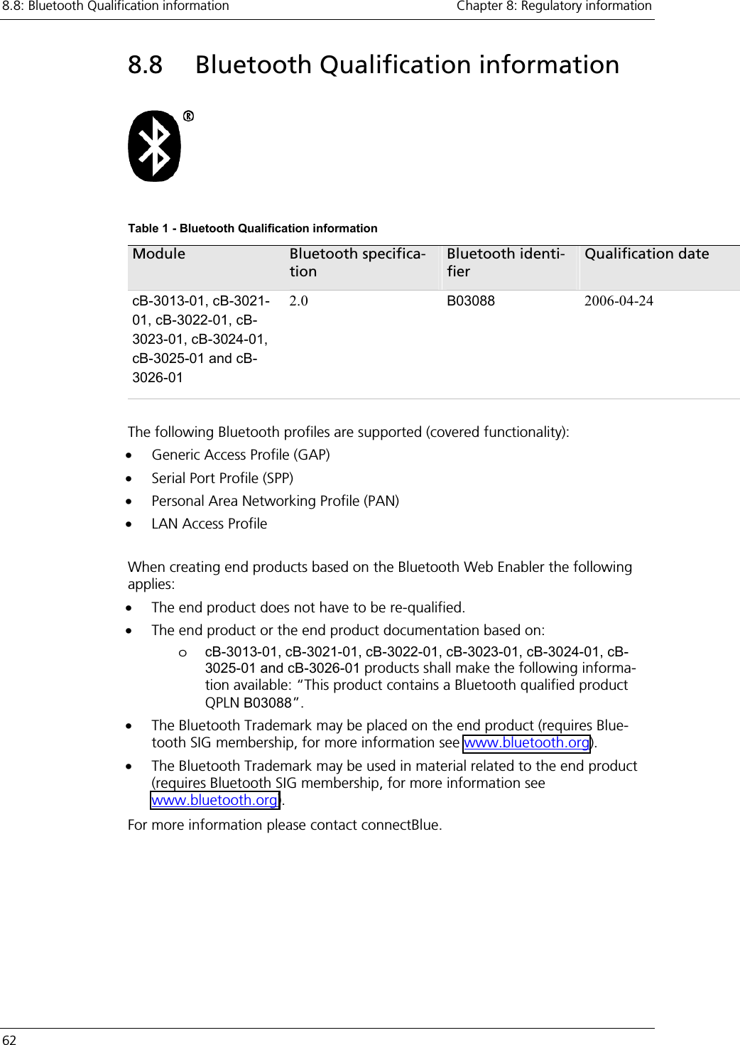
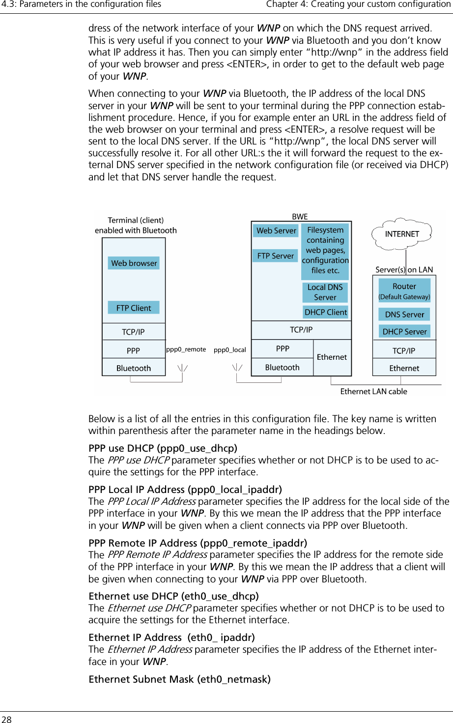
![4.3: Parameters in the configuration files Chapter 4: Creating your custom configuration 24 4.3 Parameters in the configuration files In this chapter all the configurable parameters in your WNP are described. The configuration parameters are divided into groups, where each group of parameters is located in a separate configuration file. For each of these configuration files there is a separate subsection below describing its contents. If the entry for a parameter is left out of the configuration file, it will be given a de-fault value. The default value for each parameter is specified in the summary at the end of each subsection. Modbus This group of configuration parameters is used to configure the Modbus interface in your WNP. The configuration file that contains these parameters must be named “modbus.cfg ” in your WNP. Below is a list of all the entries in this con-figuration file. The key name is written within parenthesis after the parameter name in the headings below. Serial Interface (mb_interface) The Serial Interface configuration parameter selects which type of serial interface to use (RS-232/422/485). Parity (mb_parity) The Parity configuration parameter sets which type of parity to use. Stop Bits (mb_stop_bits) The Stop Bits configuration parameter sets the number of stop bits to use. Baud Rate (mb_baud_rate) The Baud Rate configuration parameter sets which baud rate to use. Query Response Hold Time (mb_query_response_hold_time) The Query Response Hold Time specifies the time (in number 10 millisecond ticks) that your WNP shall wait after receiving a response before it may send the next query. This parameter is only applicable when RS-422/485 is used. Scan List (mb_scan_list) The Scan List configuration parameter is used to map Modbus registers in your in-dustrial equipment onto corresponding Virtual Registers in your WNP. Periodically, your WNP will poll these Modbus registers for their current value by sending Read-queries to your Modbus devices. The data that is read will then be copied to the corresponding Virtual Register in your WNP. The Scan List has the following format: “Entry;Entry2;…;EntryN;”, where each en-try defines one mapping. The entries contain a list of variables in the format “Slave,Function,Starting Virtual Register,Scan Period,Starting Slave Regis-ter,Number Of Registers”. Below is a description of what these variables mean: Variable Description Valid Value Slave The Modbus slave that this query shall be sent to. [1-255] Function The Modbus function to use when sending the query. 1, 2, 3, 4 Starting Virtual Register The Virtual Register where your WNP shall start to store the data retrieved by [0..1024]](https://usermanual.wiki/u-blox-Malmo/090103AP.Users-Manual-Host/User-Guide-661318-Page-24.png)
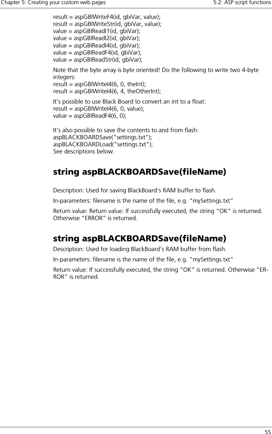
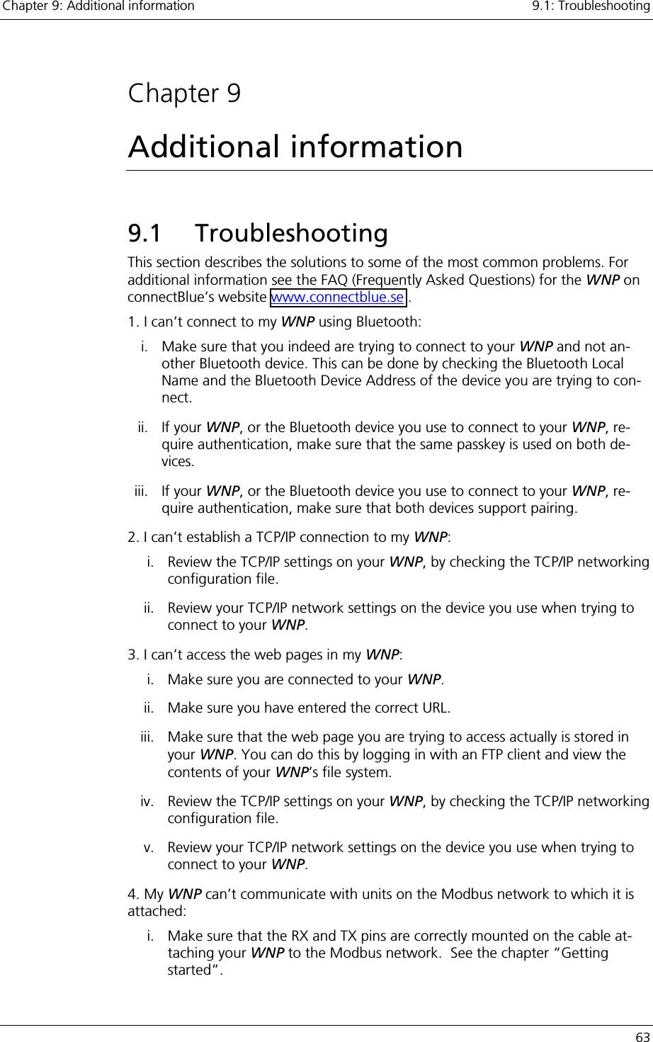
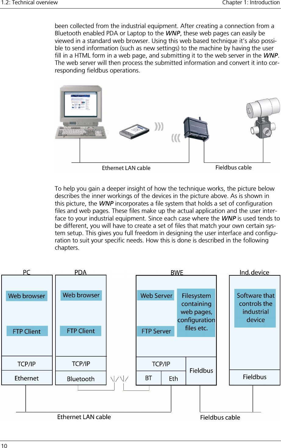
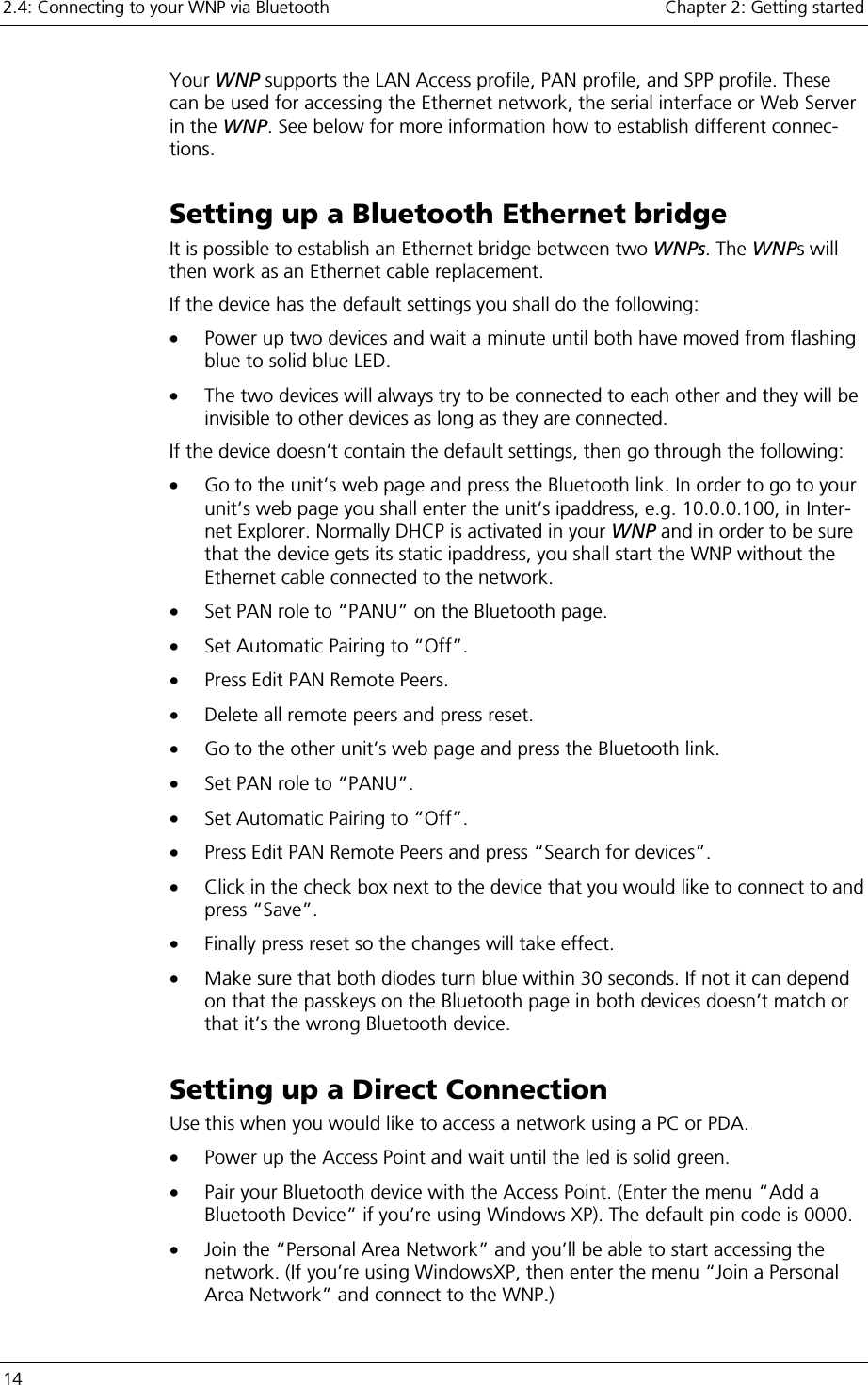
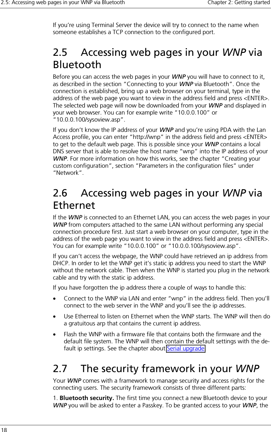
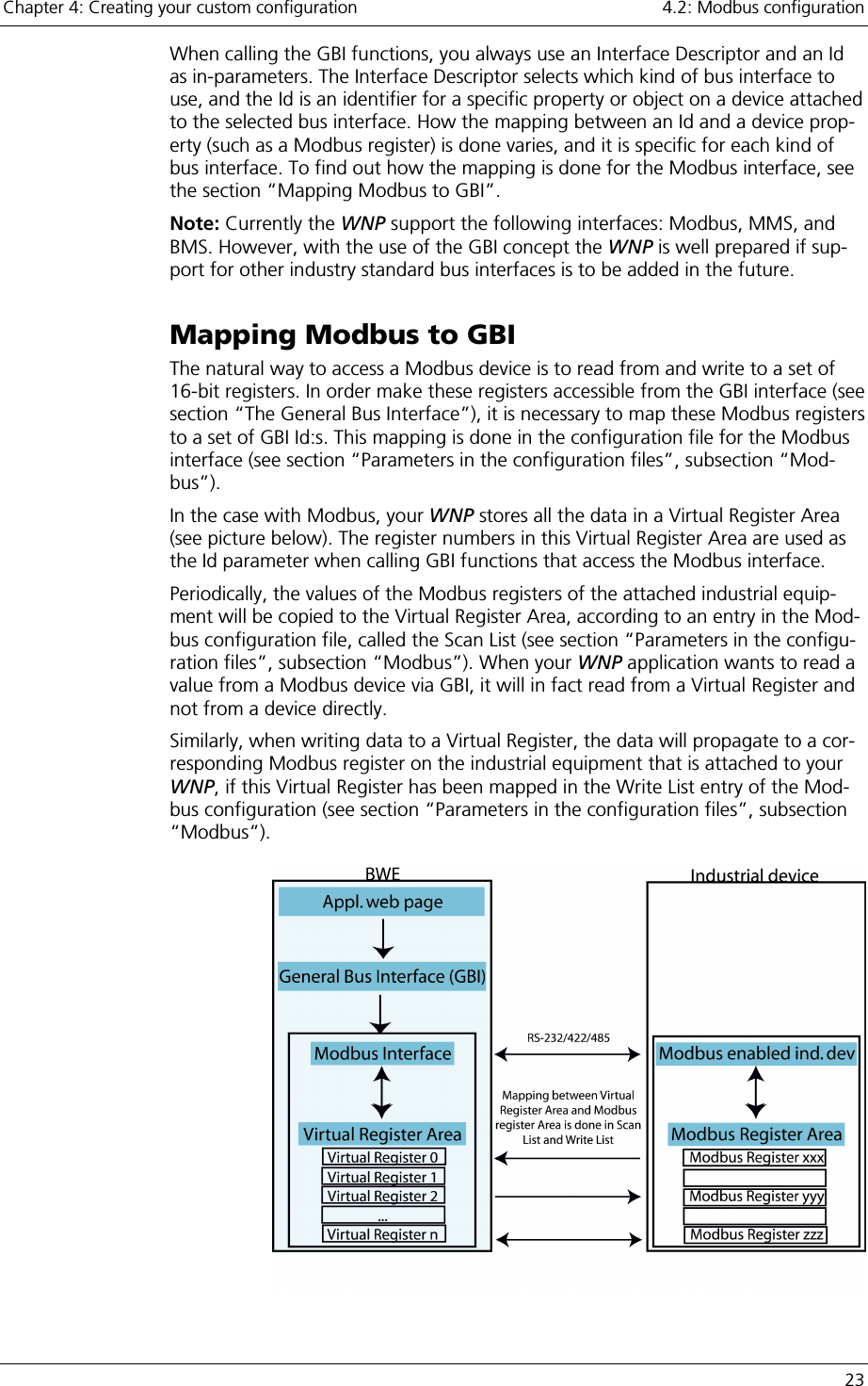
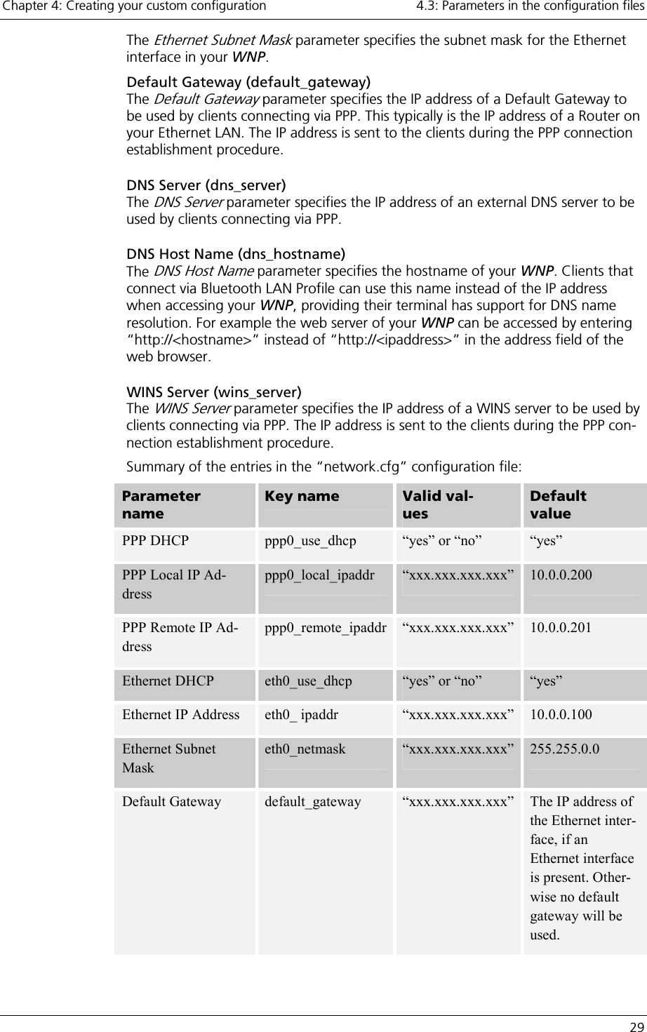
![Chapter 4: Creating your custom configuration 4.3: Parameters in the configuration files 25 this query. Scan Period The number of seconds between each refresh of the Virtual Registers [1..255] Starting Slave Register The Modbus register address in the slave where this query shall start to read from. [0..65535] Number of Registers The number of Modbus registers that shall be read by this query. [0 ..126] Note: Some slaves only support a limited number of registers to be read in one query-response operation. You must check how many registers your certain device supports. Note: The Scan List may not contain more than 20 entries. Write List (mb_write_list) The Write List configuration parameter is used to map Modbus registers in your in-dustrial equipment onto corresponding Virtual Registers in your WNP. It is only possible for your application to write to Virtual Registers that have been mapped in the Write List. When data is written to a Virtual Register in your WNP that has been mapped in the Write List, a corresponding Modbus Write-query will be sent to one of your Modbus devices. This query will tell the device to write the data that it receives in the query to one (or more) of its registers. The Write List has the following format: “Entry;Entry2;…;EntryN;”, where each en-try defines one mapping. The entries contain a list of variables in the format “Slave,Function,Starting Virtual Register,Starting Slave Register,Number Of Regis-ters”. Below is a description of what these variables mean: Variable Description Valid val-ues Slave The Modbus slave that this query shall be sent to. [1-255] Function The Modbus function to use when sending the query. 5, 6, 16 Starting Virtual Register The Virtual Register where your WNP shall start to write the data that will be sent to the slave. [0..1024] Starting Slave Register The starting Modbus register address in the slave, where the data that it receives shall be written. [0..65535] Number of Registers The maximum number of registers that can be sent to the slave when performing a write to the Starting Virtual Reg-ister in this entry. Note: The actual number of registers sent will be determined when a GBI write function is called, however it can never exceed the Number of Regis-ters specified in this entry. [0..126]](https://usermanual.wiki/u-blox-Malmo/090103AP.Users-Manual-Host/User-Guide-661318-Page-25.png)
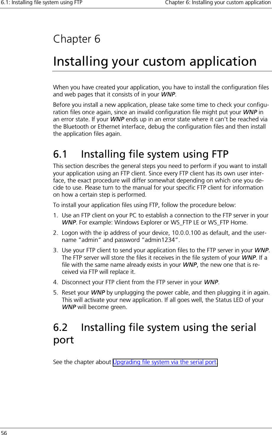
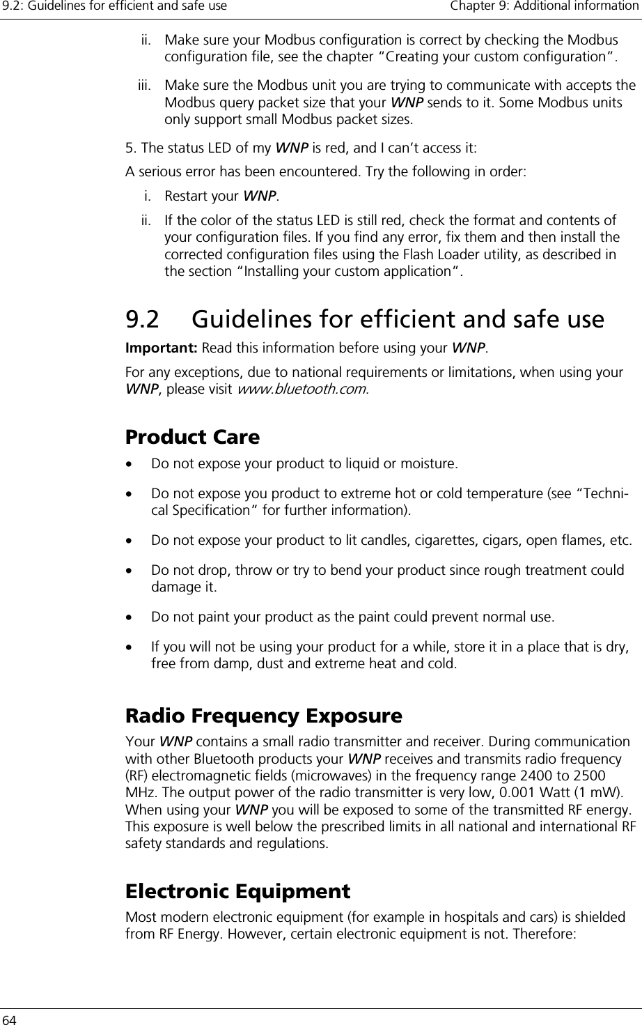
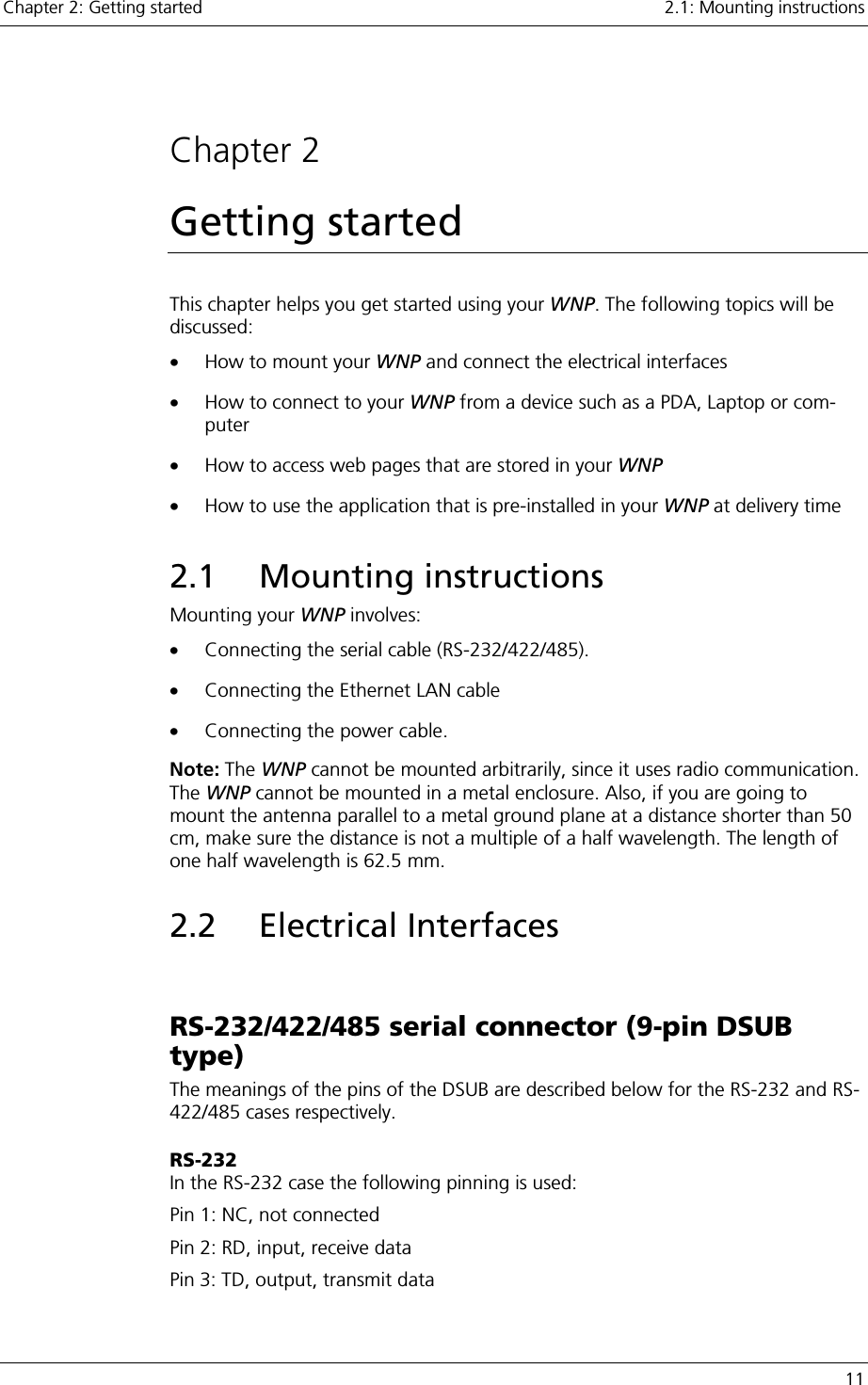
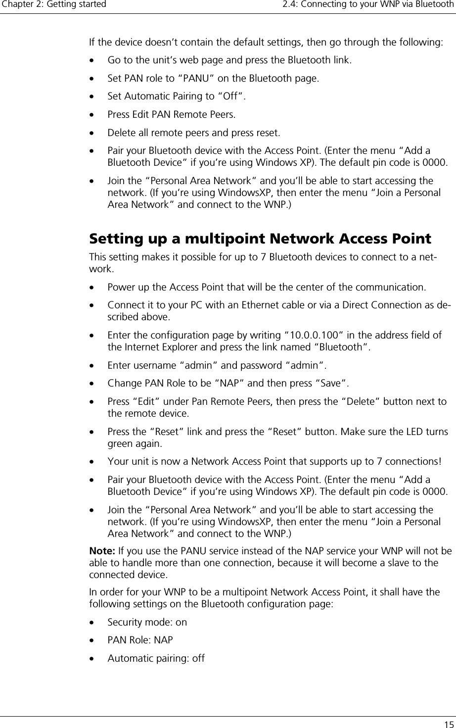
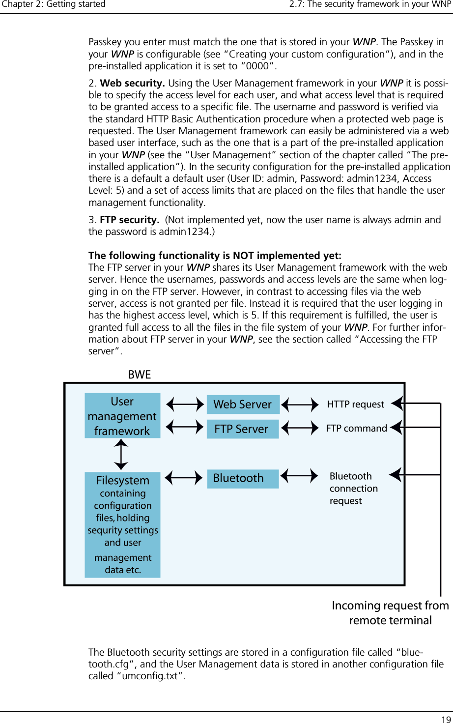
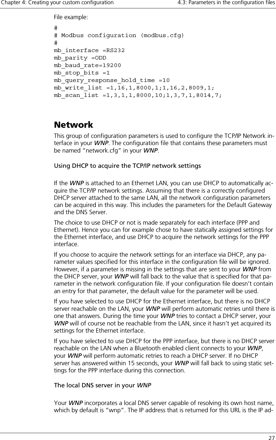
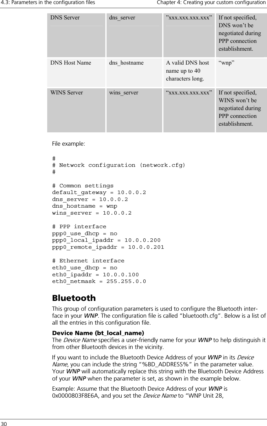
![4.3: Parameters in the configuration files Chapter 4: Creating your custom configuration 26 Note: The Write List may not contain more than 20 entries. Summary of the entries in the “modbus.cfg” configuration file: Parameter name Key name Valid values Default value Serial Interface mb_interface “RS232”, “RS422”,”RS485” RS232 Parity mb_parity “ODD”, ”EVEN”, ”NONE” ODD Stop bits mb_stop_bits “1”, ”2” 1 Baud rate mb_baud _rate “110” “300” ”1200” ”2400” ”4800” ”9600” ”19200” ”38400” ”57600” ”115200” 9600 Query Response Hold Time mb_query_response_hold_time [0..100] 0 Scan List mb_scan_list Entry1;Entry2;…;EntryN; Where each Entry = “Slave, Function, Starting Virtual Regis-ter, Scan Period, Starting Slave Register, Number of Registers;” None Write List mb_write_list Entry1;Entry2;…;EntryN; Where each Entry = “Slave, Function, Starting Virtual Reg-ister, Starting Slave Register, Number Of Registers;” None](https://usermanual.wiki/u-blox-Malmo/090103AP.Users-Manual-Host/User-Guide-661318-Page-26.png)
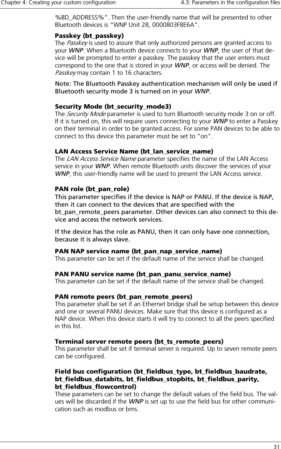
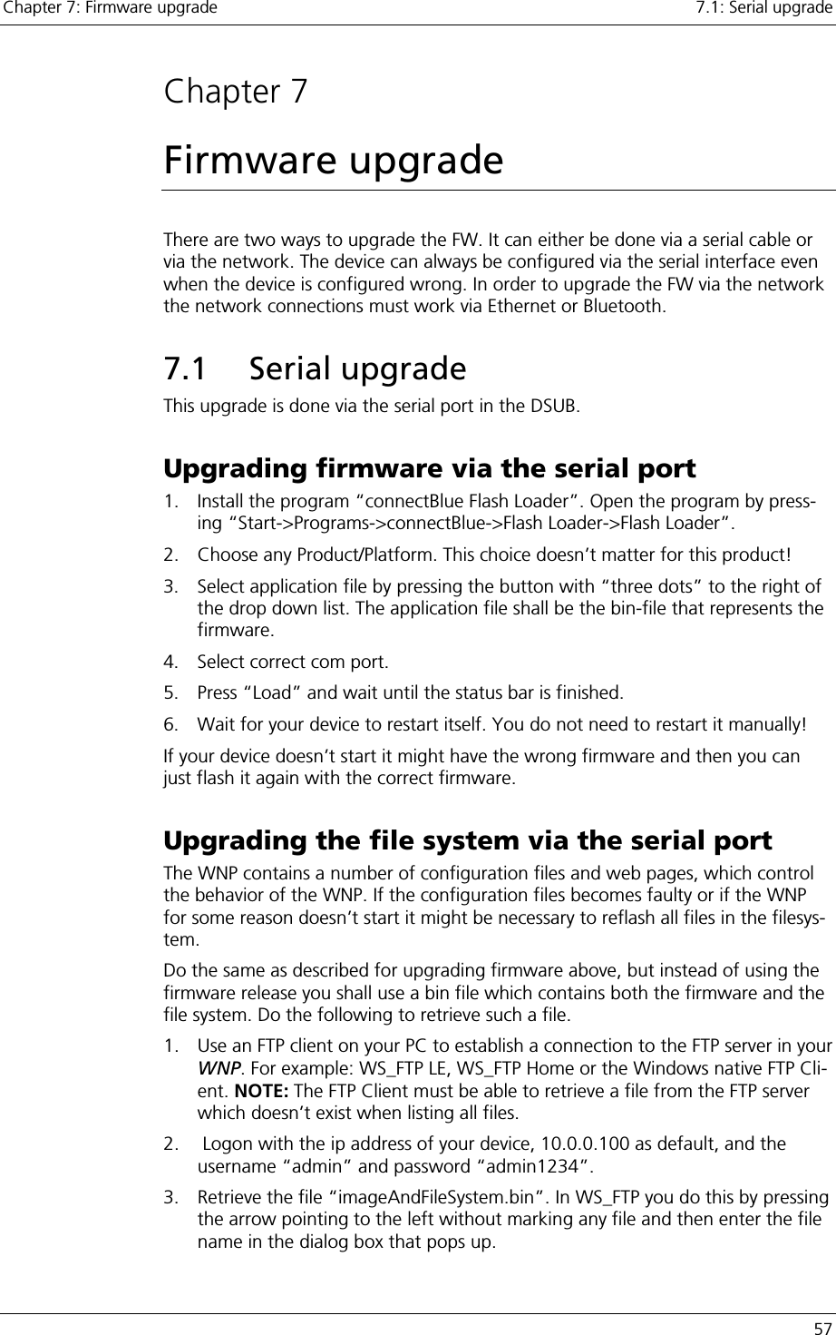
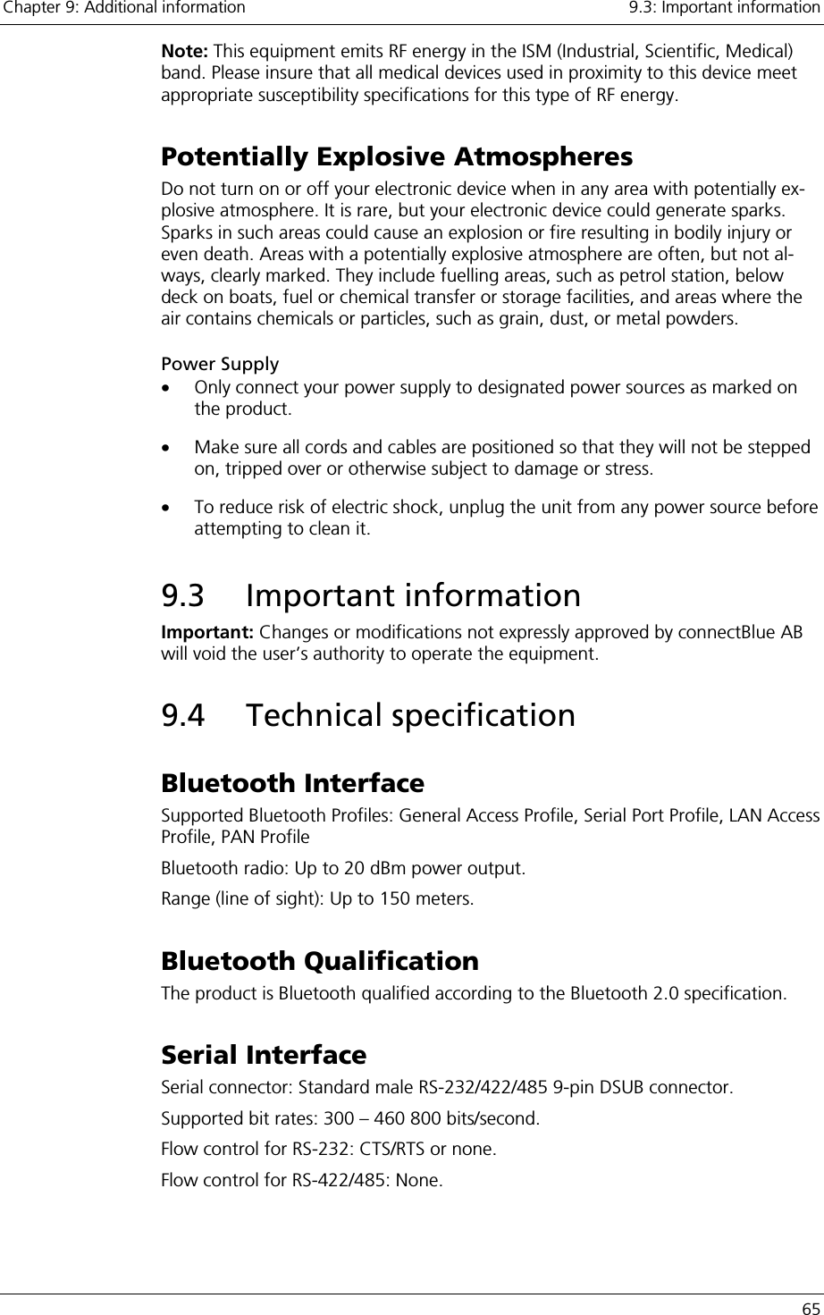
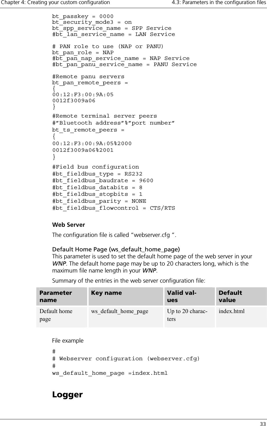
![4.3: Parameters in the configuration files Chapter 4: Creating your custom configuration 32 Summary of the entries in the Bluetooth configuration file: Parameter name Key name Valid values Default value Local Name bt_local_name Up to 80 characters Access Point Passkey bt_passkey 1 to 16 characters [A..Z][a..z][0..9] 0000 Security Mode bt_security_mode3 “on” or “off” “off” LAN Access Service Name bt_lan_service_name Up to 100 charac-ters “LAN Service” PAN role bt_pan_role “NAP” or “PANU” “NAP” PAN NAP Ser-vice Name bt_pan_nap_service_name Up to 100 charac-ters “NAP Service” PAN PANU Ser-vice Name bt_pan_panu_service_name Up to 100 charac-ters “PANU Service” Remote PANU servers bt_pan_remote_peers “{}” Remote TS serv-ers bt_ts_remote_peers “{}” Field bus type bt_fieldbus_type “RS232”, “RS422”, “RS485” “RS232” Baud rate bt_fieldbus_baudrate “9600”, ”19200”, “38400”, ”57600”, ”115200”, ”230400”, “460800” “9600” Data bits bt_fieldbus_databits “5”, “6”, “7”, “8” “8” Stop bits bt_fieldbus_stopbits “1”, “2” “1” Parity bt_fieldbus_parity “NONE”, “ODD”, “EVEN” “NONE” Flow control bt_fieldbus_flowcontrol “CTS/RTS”, “NONE” “NONE” File example: # Bluetooth configuration bt_local_name = My Bluetooth device](https://usermanual.wiki/u-blox-Malmo/090103AP.Users-Manual-Host/User-Guide-661318-Page-32.png)
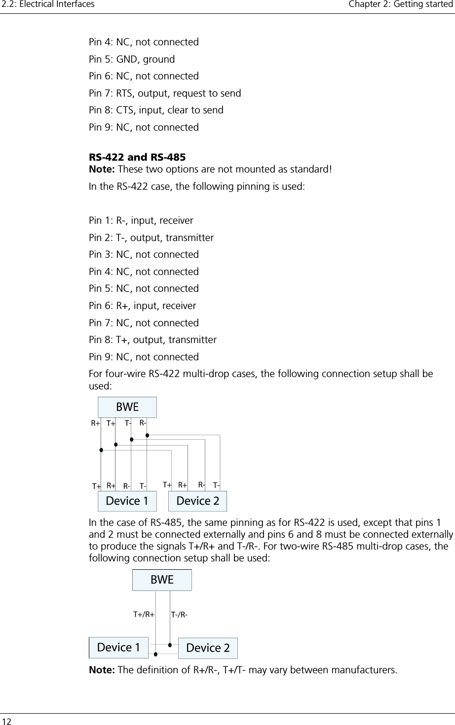
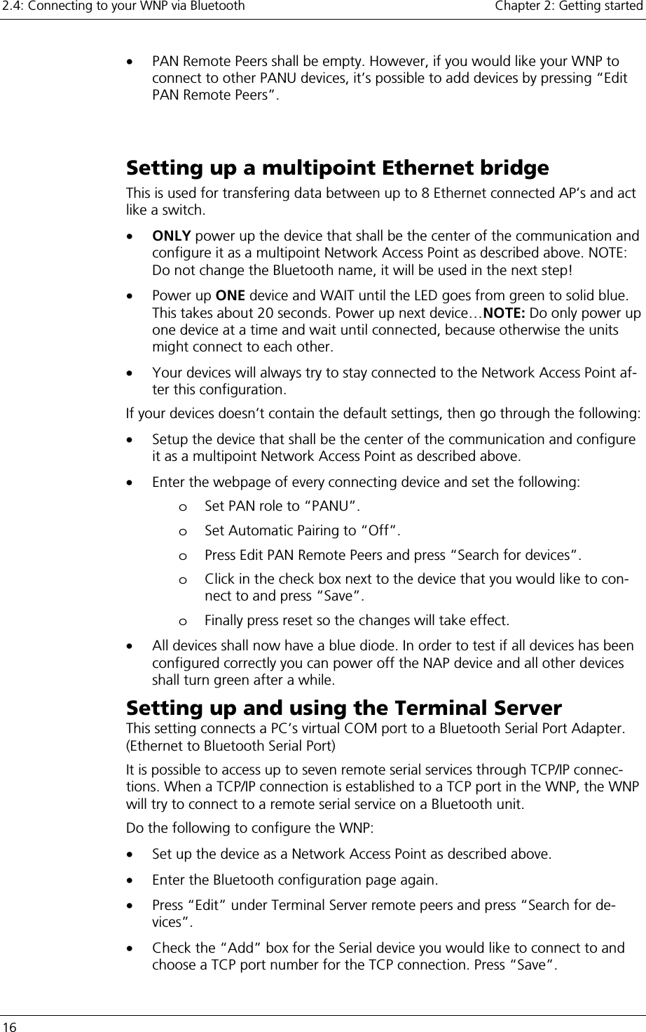
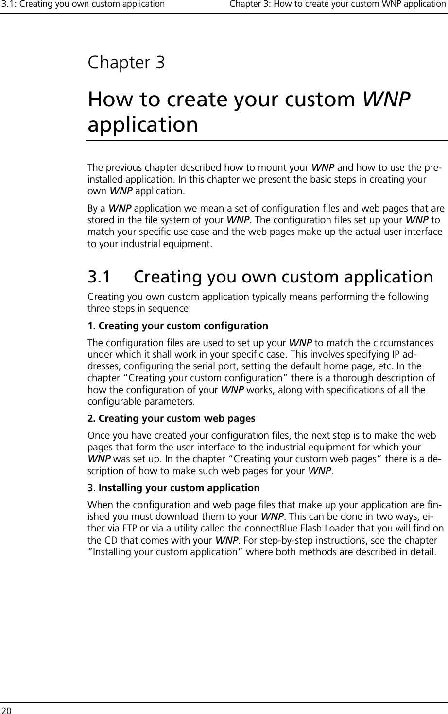
![4.3: Parameters in the configuration files Chapter 4: Creating your custom configuration 34 This group of configuration parameters is used to configure the logger in your WNP. The configuration file that contains these parameters must be named “log-ger.cfg ” in your WNP. Below is a list of all the entries in this configuration file. The key name is written within parenthesis after the parameter name in the head-ings below. Note: The Logger collects its data via the General Bus Interface (GBI). For a de-scription of this interface, see the section “The General Bus Interface”. Log List (logger_log_list) This parameter specifies which data from the industrial equipment to log. The Log List has the following format: “Entry;Entry2;…;EntryN;”, where each entry defines one GBI ID to log from a certain bus interface. The entries contain a list of variables in the format “Interface Descriptor,ID,Data Type,Hysteresis,Ring Buffer Number,Bit Number”. Below is a description of what these variables mean: Variable Description Valid values Interface Descriptor The GBI bus interface type to use. 1 ID The GBI ID to log on the selected bus interface. Bus specific Data Type The data type that shall be logged. Bit, I1Bit, I2Bit, I4Bit, I1, UI1, I2, UI2, I4, UI4 Hysteresis To actually be logged, the currently polled value must differ by at least the Hysteresis from the previously logged value for this entry. The Hysteresis vari-able only applies if the data type used is I1, UI1, I2, UI2, I4 or UI4. For the other data types the currently polled value will always be logged if it differs from the previously logged value for this entry (no hysteresis used). Example: Data Type = UI2, Hysteresis = 200 Comment Polled value nr 1 = 3428 First value is always logged Polled value nr 2 = 3571 |3428-3571| = 143 <= 200 (Hysteresis) => Value not logged Polled value nr 3 = 3112 |3428-3112| = 316 > 200 (Hysteresis) => Value logged [0..2147483647] Ring Buffer Number In which ring buffer shall the logged value be stored? 0,1](https://usermanual.wiki/u-blox-Malmo/090103AP.Users-Manual-Host/User-Guide-661318-Page-34.png)
![Chapter 4: Creating your custom configuration 4.3: Parameters in the configuration files 35 Bit Number This variable is only applicable if the data type used is I1Bit, I2Bit or I4Bit. In this case the logger will read an 1, 2 or 4 byte integer from the selected GBI ID, and if the bit Bit Number in the integer has changed from its previously logged value, the new value will be logged. For other data types this variable is ig-nored. [0..7] for I1Bit [0..15] for I2Bit [0..31] for I4Bit Log Period (logger_log_period) This parameter determines how often the entries in the Log List shall be polled for their value. The period is specified in number of seconds, and it is common for all entries in the Log List. Ring Buffer 0 (logger_ring_buffer_0) The logger has two ring buffers that are used to store the entries that are logged. The Ring Buffer 0 parameter value uses the following format: “Ring Buffer Size,Number of Backup Files”. The Ring Buffer Size variable specifies the number of entries that the ring buffer can store. The Number of Backup Files variable speci-fies the number of backup files used for the ring buffer. When an entry is stored in the ring buffer, the logger starts writing from the be-ginning of the ring buffer, and then continuously adds new entries until the end is reached. At the point when the end is reached, the logger will first save the entries in the ring buffer to a backup file in the file system (providing the ring buffer has been configured to use backup files). Then the logger will start writing at the be-ginning of the buffer again, thereby overwriting the oldest entry. Depending on how many backup files are used the following will happen when a ring buffer gets full, before the logger starts writing over old entries in the ring buffer. Number of backup files Action taken when the ring buffer gets full 0 No action will be taken. The logger will start writing over old entries immediately. 1 The entries in the ring buffer will be stored in backup file on the file system named “logbackup0_1.txt”. If a previous backup file named “logbackup0_1.txt” exists, it will be overwritten. 2 The entries in the ring buffer will be stored in backup file on the file system named “logbackup0_1.txt”. If a previous backup file named “logbackup0_1.txt” exists, it will first be renamed to “logbackup0_2.txt”. If a previous backup file named “log-backup0_2.txt” exists, it will be overwritten. For each entry logged in the ring buffer the GBI Interface Descriptor, GBI ID and a Time Stamp is stored. The format of the backup files is the same as that used when the ASP script function “aspDumpLogToFile()” is called. See chapter “Creat-](https://usermanual.wiki/u-blox-Malmo/090103AP.Users-Manual-Host/User-Guide-661318-Page-35.png)
![4.3: Parameters in the configuration files Chapter 4: Creating your custom configuration 36 ing your custom web pages”, section “ASP script functions”, sub section “Log-ger”. Ring Buffer 1 (logger_ring_buffer_1) See description of the “Ring Buffer 0” parameter. The only difference is that the backup files used are named “logbackup1_1.txt” and “logbackup1_2.txt” instead of “logbackup0_1.txt” and ““logbackup0_2.txt” respectively. Summary of the entries in the logger configuration file: Parameter name Key name Valid values Default value Log List logger_log_list Entry1;Entry2;…;EntryN; Where each Entry = “In-terface Descrip-tor,ID,Data Type,Hysteresis,Ring Buffer Number,Bit Num-ber” None Log Period logger_log_period [1.. 4294967295] 1 Ring Buffer 0 logger_ring_buffer_0 [1..1000],[0,1,2] 500,0 Ring Buffer 1 logger_ring_buffer_1 [1..1000],[0,1,2] 500,0 File example: # # Logger configuration (logger.cfg) # logger_log_list = 1,64,Bit,0,0,0;1,0,UI1,100,0,0; logger_log_period = 4 logger_ring_buffer_0 = 100,0 logger_ring_buffer_1 = 500,2 User Management To configure the User Management framework in your WNP, it is recommended that you use the User Management web pages that are a part of the pre-installed default application. Feel free to modify them as you like in order to make them match the visual design of your own custom application. It is not recommended that you manually alter the contents of the User Manage-ment configuration file named “umconfig.txt”. One of the reasons for this is that the password of a user is stored in an encrypted format in order to keep it secret from the other users on your WNP. Hence, it must be read and written by the software in your WNP, which is able to encrypt and decrypt the passwords stored in the User Management configuration file.](https://usermanual.wiki/u-blox-Malmo/090103AP.Users-Manual-Host/User-Guide-661318-Page-36.png)
![Chapter 5: Creating your custom web pages 5.1: ASP scripts 39 </BODY> </HTML> When the web server has processed this ASP web page, the following result will be returned to the client’s web browser (assuming the read temperature was 57 de-grees). <HTML> <BODY> Current Temperature = 57 </BODY> </HTML> Example2: Set a device parameter In this example we set a device parameter according to a value that is entered by the user. This is typically performed in a three-step process. 1. The first step consists of the user requesting a web page containing a HTML form, where the new parameter value can be entered: “speed_form.html” <HTML> <BODY> <FORM action=”set_new_speed.asp”> Please enter new speed: <INPUT type=”text” name=”new_speed”> <INPUT type=”submit” value=”Set Speed”> </FORM> </BODY> </HTML> 2. In the second step the user views the web page above, enters the new speed value, and presses the [Set Speed] button. This will trigger his web browser to send a request for the web page “set_new_speed.asp”. The new speed value is sent along with the request, as a CGI variable with the name “new_speed”. 3. When the web server receives the request for “set_new_speed.asp”, it detects that a CGI variable is sent along with the request. This variable (new_speed) and its value is extracted by the web server, and made available to the script code in the web page that is requested. We use this to call a script function that passes along the variable value to a fictive device. Here’s what is might look like: ”set_new_speed.asp” <HTML> <BODY> <% aspGBIWriteI2(1, 14, new_speed); %> The new speed was successfully set to <%write(new_speed);%>! </BODY> </HTML> When the web server processes this web page, it will call the script function aspGBIWriteI2 with the “new_speed” variable as input parameter. This function will make the WNP send a message to a certain device telling it to set its speed pa-rameter to the value of “new_speed”. The second script section,](https://usermanual.wiki/u-blox-Malmo/090103AP.Users-Manual-Host/User-Guide-661318-Page-39.png)
![Chapter 5: Creating your custom web pages 5.2: ASP script functions 41 In-parameters: Parameter Description Valid values variableName The name of the variable whose value shall be ex-tracted. The name of an existing web server or CGI variable Return value: The value of the selected variable is returned as a string. string aspAND(valueA, valueB) Description: Returns the result of the bit-wise logical operation “valueA AND valueB”. Both the input parameters and the return value are 32-bit signed inte-gers, specified as decimal numbers (for example 1035482 or –124691). In-parameters: valueA and valueB are the values that the AND operation is per-formed on. Return value: The result of the bit-wise logical operation “valueA AND valueB”. string aspOR(valueA, valueB) Description: Returns the result of the bit-wise logical operation “valueA OR val-ueB”. Both the input parameters and the return value are 32-bit signed integers, specified as decimal numbers (for example 1035482 or –124691). In-parameters: valueA and valueB are the values that the OR operation is per-formed on. Return value: The result of the bit-wise logical operation “valueA OR valueB”. string aspXOR(valueA, valueB) Description: Returns the result of the bit-wise logical operation “valueA XOR valueB”. Both the input parameters and the return value are 32-bit signed inte-gers, specified as decimal numbers (for example 1035482 or –124691). In-parameters: valueA and valueB are the values that the XOR operation is per-formed on. Return value: The result of the bit-wise logical operation “valueA XOR valueB”. string aspWaitTime(waitTime) Description: Halts the processing of the current web page for waitTime millisec-onds before continuing. In-parameters: Parameter Description Valid values waitTime The number of milliseconds to wait before the processing of the web page is resumed. [0..4294967295]](https://usermanual.wiki/u-blox-Malmo/090103AP.Users-Manual-Host/User-Guide-661318-Page-41.png)
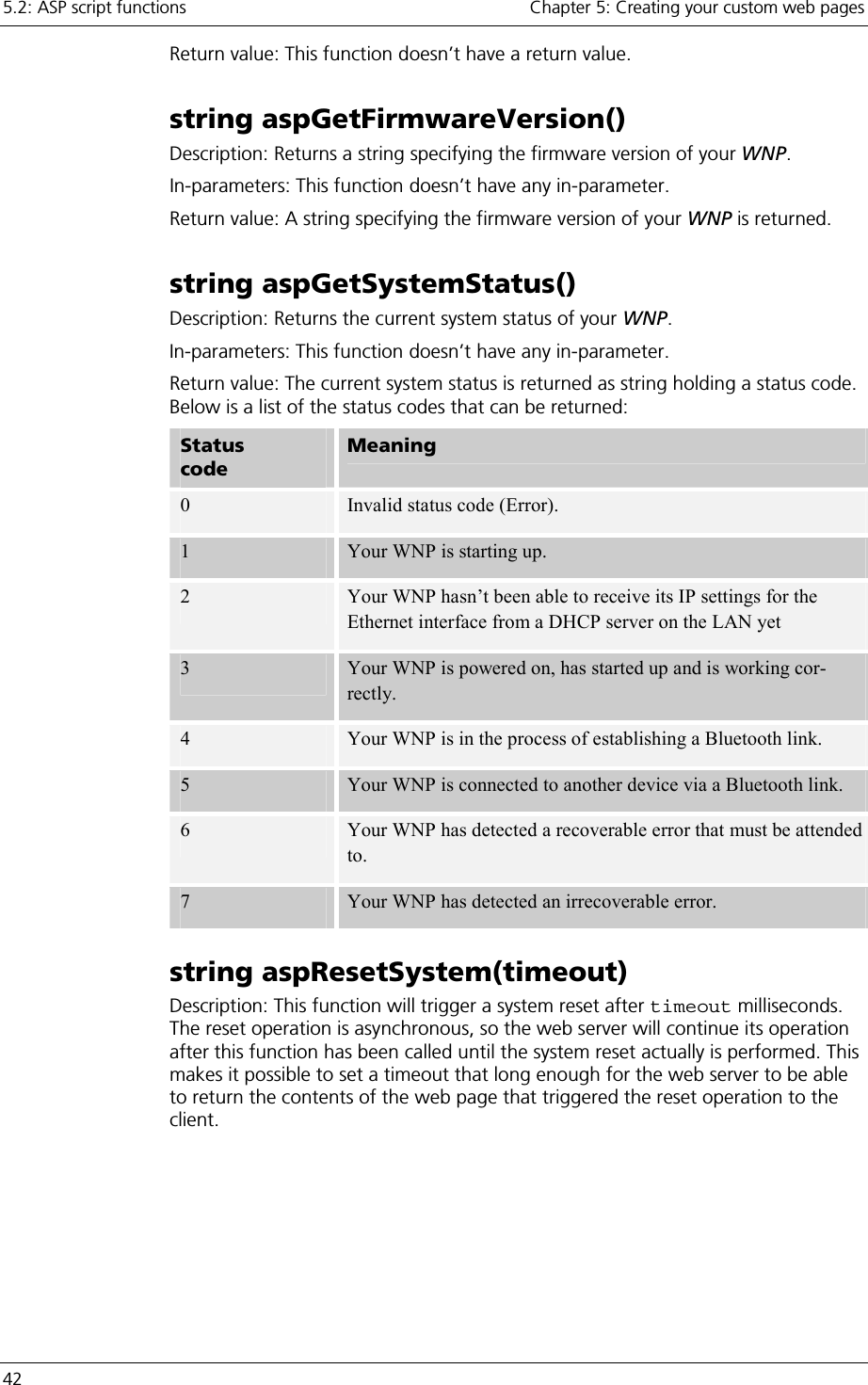
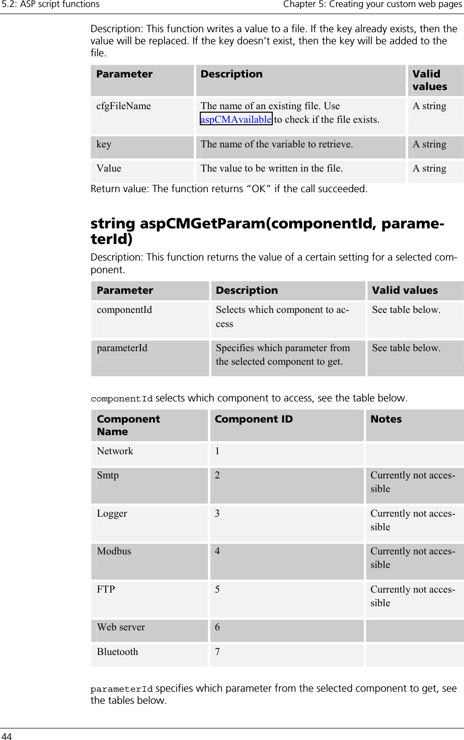
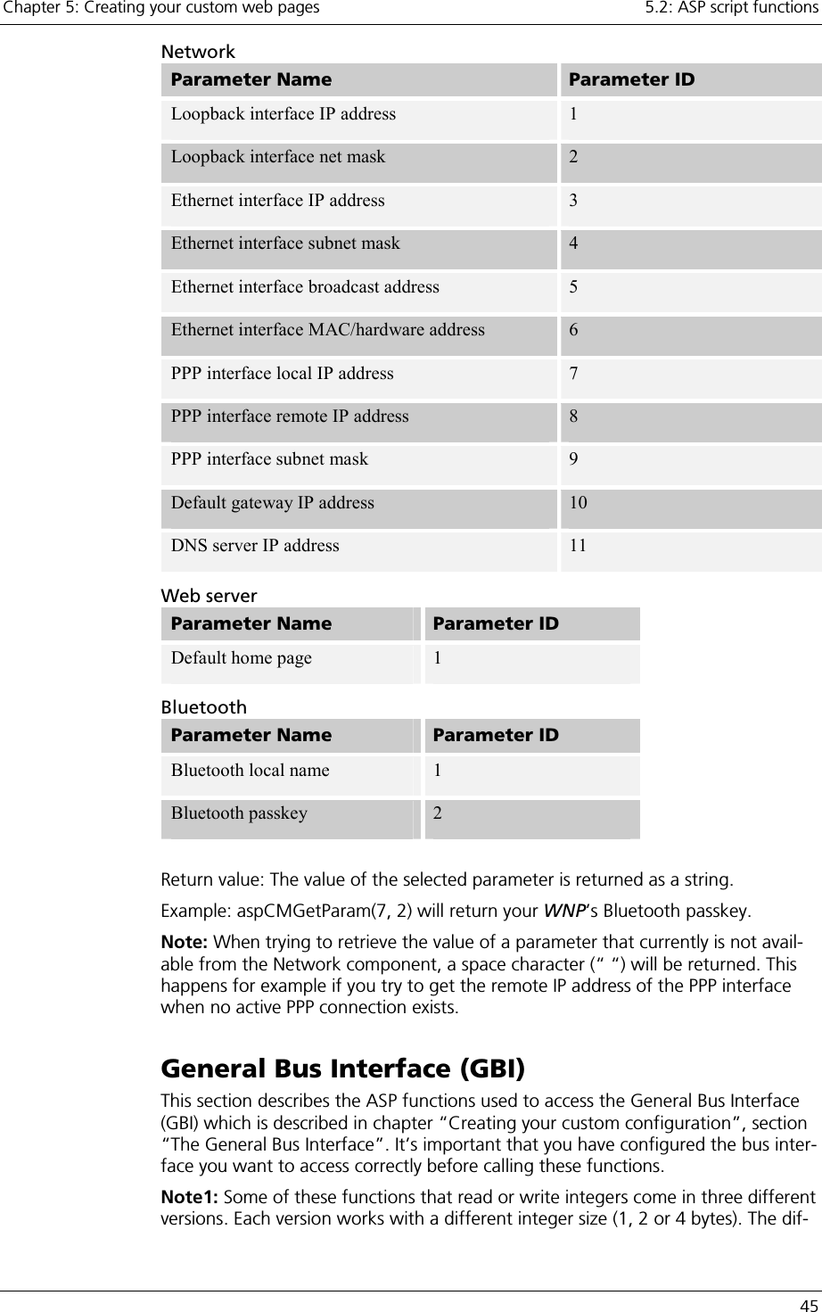
![Chapter 5: Creating your custom web pages 5.2: ASP script functions 43 In-parameters: Parameter Description Valid values timeout The number of milliseconds to wait before the web server triggers the reset. [0..30000] Return value: This function doesn’t have a return value. Configuration Manager The Configuration Manager is a part of your WNP that handles the configuration of the different components that your WNP is built up of (such as Bluetooth and the web server). Using the ASP function that accesses the Configuration Manager you can retrieve the settings for these components, in order to for example include them in a status web page. Note that with aspCMSetKeyValue and aspCMGet-KeyValues it is possible to configure all parameters in the configuration files, see chapter “Creating your custom configuration”, section ”Parameters in the con-figuration files”. string aspCMAvailable(cfgFileName) Description: This function checks whether a file exists in the WNP’s file system. In-parameters: Parameter Description Valid val-ues cfgFileName The name of the file. Any string Return value: The function returns “OK” if the file exists. string aspCMGetKeyValue(cfgFileName, key) Description: This function returns the value of a key in a file. The syntax in the file could for example be: bt_local_name = MyDevice The key is the string to the left of the equal sign and the value is the string to the right. Parameter Description Valid val-ues cfgFileName T he name of an existing file. Use aspCMAvailable to check if the file exists. A string key The name of the variable to retrieve. A string Return value: The function returns the value of the key. string aspCMSetKeyValue(cfgFileName, key, value)](https://usermanual.wiki/u-blox-Malmo/090103AP.Users-Manual-Host/User-Guide-661318-Page-43.png)
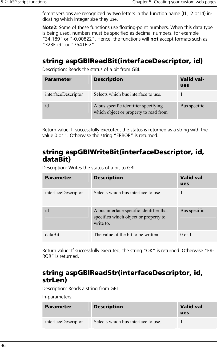
![Chapter 5: Creating your custom web pages 5.2: ASP script functions 47 id A bus interface specific identifier that specifies which object or property to read from. Bus specific strLen The number of characters to be read. [0..80] Return value: If successfully executed, the string that was read from GBI is re-turned. Otherwise the string “ERROR” is returned. Remarks: If “strLen” is set to the value “0”, the whole string will be read, until the string-terminating null-character is reached. However, if the string is longer than 80 characters, it will be truncated. string aspGBIWriteStr(interfaceDescriptor, id, “textStr”) Description: Writes a text string to GBI. Parameter Description Valid val-ues interfaceDescriptor Selects which bus interface to use. 1 id A bus specific identifier specifying which object or property to write to. Bus specific textStr The string to be written. Up to 80 charac-ters Return value: If successfully executed, the string “OK” is returned. Otherwise “ER-ROR” is returned. string aspGBIReadI1(interfaceDescriptor, id) string aspGBIReadI2(interfaceDescriptor, id) string aspGBIReadI4(interfaceDescriptor, id) Description: Reads an integer from GBI. Parameter Description Valid val-ues interfaceDescriptor Selects which bus interface to use. 1 id A bus specific identifier specifying which object or property to read from. Bus specific Return value: If successfully executed, the value of the read integer is returned as a string. Otherwise the string “ERROR” is returned.](https://usermanual.wiki/u-blox-Malmo/090103AP.Users-Manual-Host/User-Guide-661318-Page-47.png)
![5.2: ASP script functions Chapter 5: Creating your custom web pages 48 string aspGBIWriteI1(interfaceDescriptor, id, in-tegerData) string aspGBIWriteI2(interfaceDescriptor, id, in-tegerData) string aspGBIWriteI4(interfaceDescriptor, id, in-tegerData) Description: Writes an integer to GBI. Parameter Description Valid values interfaceDescriptor Selects which bus inter-face to use. 1 id A bus specific identifier specifying which object or property to write to. Bus specific integerData The value of the integer to be written. [-128..127] for integer size 1 [-32768..32767] for integer size 2[-2147483648..2147483647] for integer size I4 Return value: If successfully executed, the string “OK” is returned. Otherwise “ER-ROR” is returned. string aspGBIReadI1Dec(interfaceDescriptor, id, nrDecimals) string aspGBIReadI2Dec(interfaceDescriptor, id, nrDecimals) string aspGBIReadI4Dec(interfaceDescriptor, id, nrDecimals) Description: Reads an integer from GBI, converts it to a floating-point number, di-vides the float by 10 ^ nrDecimals, and returns the result. Parameter Description Valid val-ues interfaceDescriptor Selects which bus interface to use. 1 id A bus specific identifier specifying which object or property to read from. Bus specific nrDecimals The number of decimals to use. [-10..10]](https://usermanual.wiki/u-blox-Malmo/090103AP.Users-Manual-Host/User-Guide-661318-Page-48.png)
![Chapter 5: Creating your custom web pages 5.2: ASP script functions 49 Return value: If successfully executed, the resulting floating-point number is re-turned as a string. Otherwise the string “ERROR” is returned. Example: Integer data read from GBI =38423, nrDecimals =3 =>The floating-point number “38.423” is returned. string aspGBIWriteI1Dec(interfaceDescriptor, id, “floatData”, nrDecimals) string aspGBIWriteI2Dec(interfaceDescriptor, id, “floatData”, nrDecimals) string aspGBIWriteI4Dec(interfaceDescriptor, id, “floatData”, nrDecimals) Description: Multiplies the floating-point number stored in floatData with 10^nrDecimals, converts the result to an integer which then is written to GBI. In-parameters: Parameter Description Valid val-ues interfaceDescriptor Selects which bus interface to use. 1 id A bus specific identifier specifying which object or property to rwrite to. Bus specific floatData The floating-point number to be written. A floating-point number nrDecimals The number of decimals to use. [-10..10] Return value: If successfully executed, the string “OK” is returned. Otherwise “ER-ROR” is returned. Remarks: Please note that the resulting integer that is to be written to GBI must fit within the boundaries of the selected integer size (I1, I2 or I4). These boundaries are presented below: Integer size Boundaries I1 [-128..127] I2 [-32768..32767] I4 [-2147483648..2147483647] Example: floatData =38.423, nrDecimals =2 => The integer 3842 is written to GBI.](https://usermanual.wiki/u-blox-Malmo/090103AP.Users-Manual-Host/User-Guide-661318-Page-49.png)
![5.2: ASP script functions Chapter 5: Creating your custom web pages 50 string aspGBIReadI1Scale(interfaceDescriptor, id, “minVal”, “maxVal”, nrDecimals) string aspGBIReadI2Scale(interfaceDescriptor, id, “minVal”, “maxVal”, nrDecimals) string aspGBIReadI4Scale(interfaceDescriptor, id, “minVal”, “maxVal”, nrDecimals) Description: Reads an integer from GBI and maps/scales it to a floating-point num-ber, which is returned. The floating-point number will be within the range min-Val to maxVal. In-parameters: Parameter Description Valid val-ues interfaceDescriptor Selects which bus interface to use. 1 id A bus specific identifier specifying which object or property to read from. Bus specific minval The lowest point on the floating-point scale. A floating-point number maxval The highest point on the floating-point scale. A floating-point number decimalPrecision The number of decimals to be used for the return value. [-10..10] Return value: If successfully executed, the resulting floating-point number is re-turned as a string. Otherwise the string “ERROR” is returned. string aspGBIWriteI1Scale(interfaceDescriptor, id, “minVal”, “maxVal”, “floatData”) string aspGBIWriteI2Scale(interfaceDescriptor, id, “minVal”, “maxVal”, “floatData”) string aspGBIWriteI4Scale(interfaceDescriptor, id, “minVal”, “maxVal”, “floatData”) Description: Maps/scales the floating-point number stored in floatData to an in-teger. The float number must be within the range minVal to maxVal. Parameter Description Valid values interfaceDescriptor Selects which bus interface to use. 1](https://usermanual.wiki/u-blox-Malmo/090103AP.Users-Manual-Host/User-Guide-661318-Page-50.png)
![Chapter 5: Creating your custom web pages 5.2: ASP script functions 51 id A bus specific identifier specifying which object or property to write to. Bus specific minval The lowest point on the floating-point scale. A floating-point number maxval The highest point on the floating-point scale. A floating-point number floatData The floating-point number to be writ-ten. [minVal..maxVal] Return value: If successfully executed, the string “OK” is returned. Otherwise “ER-ROR” is returned. string aspGBIReadI1Time(interfaceDescriptor, id) string aspGBIReadI2Time(interfaceDescriptor, id) string aspGBIReadI4Time(interfaceDescriptor, id) Description: Reads an integer from GBI holding a time value specified in number of seconds, and then converts it to a string in the format “hh:mm:ss ” which is re-turned. Parameter Description Valid val-ues interfaceDescriptor Selects which bus interface to use. 1 id A bus specific identifier specifying which object or property to read from. Bus specific Return value: If successfully executed, the time is returned as a string in the format “hh:mm:ss”. Otherwise the string “ERROR” is returned. string aspGBIWriteI1Time(interfaceDescriptor, id, ”time”) string aspGBIWriteI2Time(interfaceDescriptor, id, ”time”) string aspGBIWriteI4Time(interfaceDescriptor, id, ”time”)](https://usermanual.wiki/u-blox-Malmo/090103AP.Users-Manual-Host/User-Guide-661318-Page-51.png)
![5.2: ASP script functions Chapter 5: Creating your custom web pages 52 Description: Converts the string time specified in the format “hh:mm:ss” to num-ber of seconds and then writes this as an integer to GBI. Parameter Description Valid val-ues interfaceDescriptor Selects which bus interface to use. 1 id A bus specific identifier specifying which object or property to write to. Bus specific time A string holding the time to be written. hh:mm:ss Return value: If successfully executed, the string “OK” is returned. Otherwise “ER-ROR” is returned. Remarks: Please note that the resulting integer that is to be written to GBI must fit within the boundaries of the selected integer size (I1, I2 or I4). These boundaries are presented below: Integer size Boundaries I1 [-128..127] I2 [-32768..32767] I4 [-2147483648..2147483647] Real Time Clock This chapter describes the functions used to access the Real Time Clock (RTC) in your WNP. Using these functions, you can set and get the date and time of your WNP. string aspRTCGetTime() Description: Returns the current time of the RTC in your WNP as a string with the format “hh:mm:ss”. In-parameters: This function doesn’t have any in-parameter. Return value: If successfully executed, this function returns the current time of the RTC in your WNP as a string with the format “hh:mm:ss”. If the power to the RTC has been lost, the string “Power lost” is returned. If a general error in the RTC has been detected “ERROR” is returned. string aspRTCSetTime(“time”) Description: Sets the time of the RTC in your WNP according to the time string, specified in the format “hh:mm:ss”. Parameter Description Valid values time A string holding the time which the RTC shall be set to. [0..23]:[0..59]:[0..59]](https://usermanual.wiki/u-blox-Malmo/090103AP.Users-Manual-Host/User-Guide-661318-Page-52.png)
![Chapter 5: Creating your custom web pages 5.2: ASP script functions 53 Return value: If successfully executed, the string “OK” is returned. Otherwise “ER-ROR” is returned. string aspRTCGetDate() Description: Returns the current date of the RTC in your WNP as a string with the format “20yy/mm/dd”. In-parameters: This function doesn’t have any in-parameter. Return value: If successfully executed, this function returns the current date of the RTC in your WNP is returned as a string with the format “20yy/mm/dd”. If the power to the RTC has been lost, the string “Power lost” is returned. If a general error in the RTC has been detected the “ERROR” is returned. string aspRTCSetDate(“date”) Description: Sets the date of the RTC in your WNP according to the date string, specified in the format “20yy/mm/dd”. Parameter Description Valid values time A string holding the date which the RTC shall be set to. [2000..2037]/[1..12]/[1..31] Return value: If successfully executed, the string “OK” is returned. Otherwise “ER-ROR” is returned. Logger string aspDumpLogToFile(“filename”, ring-BufferNumber) Description: Dumps the entries currently stored in one of the Logger’s ring-buffers to a file. In-parameters: Parameter Description Valid val-ues filename The name of the file to which the Log-ger entries shall be written. Up to 20 charac-ters ringBufferNumber The number of the ring buffer that contains the entries to be stored. 1,2 Return value: This function doesn’t have a return value. Remarks: The log file that is created as a result of calling this function contains a list of log entries. Each entry is placed on a separate line, and consists of a comma-separated list of variables in the following format “Interface Descriptor,ID,](https://usermanual.wiki/u-blox-Malmo/090103AP.Users-Manual-Host/User-Guide-661318-Page-53.png)