u blox Malmo 090103AP Wireless Communication System Module User Manual Bluetooth Web Enabler
u-blox Malmo AB Wireless Communication System Module Bluetooth Web Enabler
Contents
- 1. Integration Manual Host
- 2. Users Manual Host
- 3. Integration Manual I
- 4. Integration Manual II
Users Manual Host

INDUSTRIAL BLUETOOTH™
Wireless Network Platform
User Manual 3.6
Wireless Network Platform
User Manual 3.6

Copyright © 2006 connectBlue AB.
The contents of this document can be changed by connectBlue AB without prior
notice and do not constitute any binding undertakings from connectBlue AB. con-
nectBlue AB is not responsible under any circumstances for direct, indirect, unex-
pected damage or consequent damage that is caused by this document.
All rights reserved.
Release: 0512
Document version: 3.4
Document number: cBProduct-0111-04
Printed in Sweden.
Trademarks
Registered trademarks from other companies are: Bluetooth is a trademark owned
by the Bluetooth SIG,Inc. Microsoft ™,Windows ™,Windows NT ™,Windows
2000 ™, Windows CE ™,Windows ME ™,are registered trademarks from Micro-
soft Corporation.

5
Contents
1. Introduction 9
1.1 What is Bluetooth wireless technology? ............................................9
1.2 Technical overview.............................................................................9
2. Getting started 11
2.1 Mounting instructions .......................................................................11
2.2 Electrical Interfaces..........................................................................11
RS-232/422/485 serial connector (9-pin DSUB type)..................11
Power Connector .........................................................................13
2.3 Status LEDs .....................................................................................13
System status LED ......................................................................13
LAN Valid Link and LAN Link Activity LED ..................................13
Serial Activity LED........................................................................13
2.4 Connecting to your WNP via Bluetooth............................................13
Setting up a Bluetooth Ethernet bridge........................................14
Setting up a Direct Connection ....................................................14
Setting up a multipoint Network Access Point .............................15
Setting up a multipoint Ethernet bridge........................................16
Connecting using the LAN Access profile....................................17
Connecting to the WNP as a Serial Port Adapter ........................17
Connect to name and roaming.....................................................17
2.5 Accessing web pages in your WNP via Bluetooth ...........................18
2.6 Accessing web pages in your WNP via Ethernet.............................18
2.7 The security framework in your WNP ..............................................18
3. How to create your custom WNP application 20
3.1 Creating you own custom application ..............................................20
4. Creating your custom configuration 21
4.1 Configuration files ............................................................................21
File format ....................................................................................22
4.2 Modbus configuration.......................................................................22
The General Bus Interface (GBI) .................................................22
Mapping Modbus to GBI ..............................................................23
4.3 Parameters in the configuration files................................................24
Modbus 24
Network 27
Bluetooth ......................................................................................30
Logger 33
User Management .......................................................................36
5. Creating your custom web pages 37
5.1 ASP scripts.......................................................................................37
Commands in the GoAhead's JavaScript Interpreter ..................38
Example1: Present data in a web page .......................................38
Example2: Set a device parameter..............................................39
5.2 ASP script functions .........................................................................40

Contents
6
General functions ........................................................................ 40
string aspVarExists(variableName)............................................. 40
string aspGetVar(variableName)................................................. 40
string aspAND(valueA, valueB)................................................... 41
string aspOR(valueA, valueB)..................................................... 41
string aspXOR(valueA, valueB) .................................................. 41
string aspWaitTime(waitTime)..................................................... 41
string aspGetFirmwareVersion() ................................................. 42
string aspGetSystemStatus() ...................................................... 42
string aspResetSystem(timeout) ................................................. 42
Configuration Manager................................................................ 43
string aspCMAvailable(cfgFileName).......................................... 43
string aspCMGetKeyValue(cfgFileName, key) ........................... 43
string aspCMSetKeyValue(cfgFileName, key, value) ................. 43
string aspCMGetParam(componentId, parameterId).................. 44
General Bus Interface (GBI)........................................................ 45
string aspGBIReadBit(interfaceDescriptor, id) ............................ 46
string aspGBIWriteBit(interfaceDescriptor, id, dataBit) ............... 46
string aspGBIReadStr(interfaceDescriptor, id, strLen)................ 46
string aspGBIWriteStr(interfaceDescriptor, id, “textStr”) ............. 47
string aspGBIReadI1(interfaceDescriptor, id) ............................. 47
string aspGBIReadI2(interfaceDescriptor, id) ............................. 47
string aspGBIReadI4(interfaceDescriptor, id) ............................. 47
string aspGBIWriteI1(interfaceDescriptor, id, integerData)......... 48
string aspGBIWriteI2(interfaceDescriptor, id, integerData)......... 48
string aspGBIWriteI4(interfaceDescriptor, id, integerData)......... 48
string aspGBIReadI1Dec(interfaceDescriptor, id, nrDecimals)... 48
string aspGBIReadI2Dec(interfaceDescriptor, id, nrDecimals)... 48
string aspGBIReadI4Dec(interfaceDescriptor, id, nrDecimals)... 48
string aspGBIWriteI1Dec(interfaceDescriptor, id, “floatData”,
nrDecimals).................................................................... 49
string aspGBIWriteI2Dec(interfaceDescriptor, id, “floatData”,
nrDecimals).................................................................... 49
string aspGBIWriteI4Dec(interfaceDescriptor, id, “floatData”,
nrDecimals).................................................................... 49
string aspGBIReadI1Scale(interfaceDescriptor, id, “minVal”,
“maxVal”, nrDecimals) ................................................... 50
string aspGBIReadI2Scale(interfaceDescriptor, id, “minVal”,
“maxVal”, nrDecimals) ................................................... 50
string aspGBIReadI4Scale(interfaceDescriptor, id, “minVal”,
“maxVal”, nrDecimals) ................................................... 50
string aspGBIWriteI1Scale(interfaceDescriptor, id, “minVal”,
“maxVal”, “floatData”)..................................................... 50
string aspGBIWriteI2Scale(interfaceDescriptor, id, “minVal”,
“maxVal”, “floatData”)..................................................... 50
string aspGBIWriteI4Scale(interfaceDescriptor, id, “minVal”,
“maxVal”, “floatData”)..................................................... 50
string aspGBIReadI1Time(interfaceDescriptor, id) ..................... 51
string aspGBIReadI2Time(interfaceDescriptor, id) ..................... 51
string aspGBIReadI4Time(interfaceDescriptor, id) ..................... 51
string aspGBIWriteI1Time(interfaceDescriptor, id, ”time”) .......... 51
string aspGBIWriteI2Time(interfaceDescriptor, id, ”time”) .......... 51
string aspGBIWriteI4Time(interfaceDescriptor, id, ”time”) .......... 51
Real Time Clock .......................................................................... 52
string aspRTCGetTime() ............................................................. 52
string aspRTCSetTime(“time”) .................................................... 52
string aspRTCGetDate().............................................................. 53
string aspRTCSetDate(“date”) .................................................... 53
Logger 53

Introduction
7
string aspDumpLogToFile(“filename”, ringBufferNumber)...........53
User Management .......................................................................54
Black Board..................................................................................54
string aspBLACKBOARDSave(fileName)....................................55
string aspBLACKBOARDSave(fileName)....................................55
6. Installing your custom application 56
6.1 Installing file system using FTP .......................................................56
6.2 Installing file system using the serial port ........................................56
7. Firmware upgrade 57
7.1 Serial upgrade..................................................................................57
Upgrading firmware via the serial port .........................................57
Upgrading the file system via the serial port ................................57
7.2 Network upgrade..............................................................................58
8. Regulatory information 59
8.1 Declaration of conformity .................................................................59
8.2 FCC Statement ................................................................................60
Antenna........................................................................................60
Caution 60
8.3 IC Compliance..................................................................................60
8.4 Safety 61
8.5 RF-exposure Statement ...................................................................61
8.6 UL listing information........................................................................61
8.7 Compliance with RoHS directive......................................................61
8.8 Bluetooth Qualification information ..................................................62
9. Additional information 63
9.1 Troubleshooting ...............................................................................63
9.2 Guidelines for efficient and safe use................................................64
Product Care ................................................................................64
Radio Frequency Exposure .........................................................64
Electronic Equipment ...................................................................64
Potentially Explosive Atmospheres..............................................65
9.3 Important information .......................................................................65
9.4 Technical specification .....................................................................65
Bluetooth Interface .......................................................................65
Bluetooth Qualification .................................................................65
Serial Interface .............................................................................65
Power/current consumption .........................................................66
File system ...................................................................................66
Configuration Files .......................................................................66
Compatibility.................................................................................66
Environmental ..............................................................................66

Contents
8

Chapter 1: Introduction 1.1: What is Bluetooth wireless technology?
9
Chapter 1
Introduction
The Wireless Network Platform™ (in this manual referred to as the WNP) works as
a Wireless Access Point, an Ethernet Port Adapter, a Serial Port Adapter and as a
Terminal Server that forwards data from a TCP connection to a Bluetooth SPP con-
nection.
It can also be used to add a standard web based user interface to industrial ma-
chines. It’s then possible to use a web browser to view the machine’s user inter-
face, it’s easy to control the machine or configure it from standard devices such as
laptops and PDA:s without the need for development and installation of proprie-
tary client-side software.
1.1 What is Bluetooth wireless technol-
ogy?
Bluetooth makes it possible to connect any compatible portable and stationary
communications device without using cables. The technology uses a radio link that
offers fast and reliable transmission of voice and data information. Due to the na-
ture of radio technology, there is no need for a free line-of-sight between devices
that wish to communicate with each other. The Bluetooth wireless technology uses
a globally available frequency range intended to ensure communication compati-
bility worldwide. Bluetooth is very often standard in for example mobile phones,
laptops and handheld computers.
1.2 Technical overview
The WNP works as a Wireless Access Point with the PAN and LAN profile. It sup-
ports up to 7 Bluetooth connections.
When the WNP works as an Ethernet Port Adapter it establishes a connection to
one or several other WNPs. In this scenario the WNP forwards all data from the
Ethernet cable to all connected peers. A switch will filter unwanted mac addresses.
The WNP can work as a Serial Port Adapter, because it always has an SPP service
enabled. When another device connects to this service the WNP will forward all
the data from the Bluetooth connection to the physical serial port.
There is also a scenario where the WNP act as a Terminal Server. In this case the
WNP waits for a TCP connection from Ethernet and starts a Bluetooth connection
when someone connects to the preconfigured TCP port. All data that is sent on
the TCP connection is sent to the Bluetooth SPP connection.
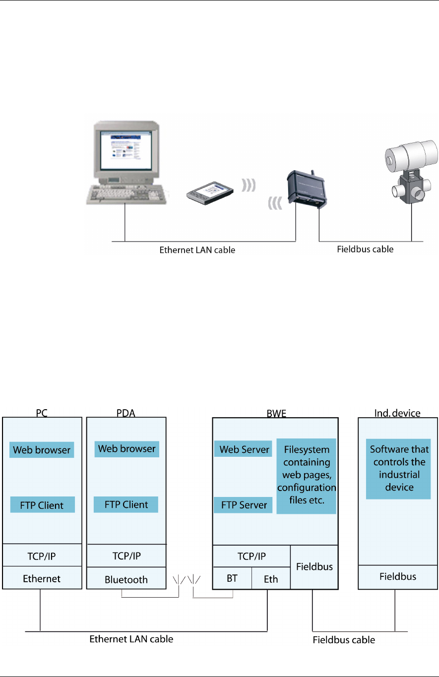
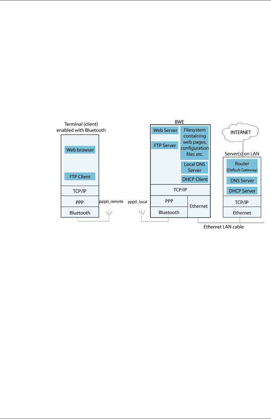
In the picture below there’s an illustration of a system setup where the WNP is
working as a Web Enabler and is attached via a serial cable to a machine.
To be able to present this information, the WNP incorporates a small web server
together with a set of web pages that dynamically can include the data that has
1.2: Technical overview Chapter 1: Introduction
10
been collected from the industrial equipment. After creating a connection from a
Bluetooth enabled PDA or Laptop to the WNP, these web pages can easily be
viewed in a standard web browser. Using this web based technique it’s also possi-
ble to send information (such as new settings) to the machine by having the user
fill in a HTML form in a web page, and submitting it to the web server in the WNP.
The web server will then process the submitted information and convert it into cor-
responding fieldbus operations.
To help you gain a deeper insight of how the technique works, the picture below
describes the inner workings of the devices in the picture above. As is shown in
this picture, the WNP incorporates a file system that holds a set of configuration
files and web pages. These files make up the actual application and the user inter-
face to your industrial equipment. Since each case where the WNP is used tends to
be different, you will have to create a set of files that match your own certain sys-
tem setup. This gives you full freedom in designing the user interface and configu-
ration to suit your specific needs. How this is done is described in the following
chapters.

Chapter 2: Getting started 2.1: Mounting instructions
11
Chapter 2
Getting started
This chapter helps you get started using your WNP. The following topics will be
discussed:
• How to mount your WNP and connect the electrical interfaces
• How to connect to your WNP from a device such as a PDA, Laptop or com-
puter
• How to access web pages that are stored in your WNP
• How to use the application that is pre-installed in your WNP at delivery time
2.1 Mounting instructions
Mounting your WNP involves:
• Connecting the serial cable (RS-232/422/485).
• Connecting the Ethernet LAN cable
• Connecting the power cable.
Note: The WNP cannot be mounted arbitrarily, since it uses radio communication.
The WNP cannot be mounted in a metal enclosure. Also, if you are going to
mount the antenna parallel to a metal ground plane at a distance shorter than 50
cm, make sure the distance is not a multiple of a half wavelength. The length of
one half wavelength is 62.5 mm.
2.2 Electrical Interfaces
RS-232/422/485 serial connector (9-pin DSUB
type)
The meanings of the pins of the DSUB are described below for the RS-232 and RS-
422/485 cases respectively.
RS-232
In the RS-232 case the following pinning is used:
Pin 1: NC, not connected
Pin 2: RD, input, receive data
Pin 3: TD, output, transmit data
2.2: Electrical Interfaces Chapter 2: Getting started
12
Pin 4: NC, not connected
Pin 5: GND, ground
Pin 6: NC, not connected
Pin 7: RTS, output, request to send
Pin 8: CTS, input, clear to send
Pin 9: NC, not connected
RS-422 and RS-485
Note: These two options are not mounted as standard!
In the RS-422 case, the following pinning is used:
Pin 1: R-, input, receiver
Pin 2: T-, output, transmitter
Pin 3: NC, not connected
Pin 4: NC, not connected
Pin 5: NC, not connected
Pin 6: R+, input, receiver
Pin 7: NC, not connected
Pin 8: T+, output, transmitter
Pin 9: NC, not connected
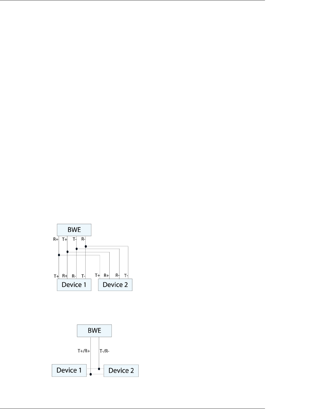
For four-wire RS-422 multi-drop cases, the following connection setup shall be
used:
In the case of RS-485, the same pinning as for RS-422 is used, except that pins 1
and 2 must be connected externally and pins 6 and 8 must be connected externally
to produce the signals T+/R+ and T-/R-. For two-wire RS-485 multi-drop cases, the
following connection setup shall be used:
Note: The definition of R+/R-, T+/T- may vary between manufacturers.

Chapter 2: Getting started 2.3: Status LEDs
13
Power Connector
TBD
Power, 9-30 V DC
2.3 Status LEDs
System status LED
The color of the LED that’s placed next to the ))) sign on the top of your WNP indi-
cates the system status.
• Solid green and blue led at the same time means that your WNP is starting
up. The WNP is not working if it stays in this mode.
• Blinking green (1 to 5 blinks per second) means that your WNP is getting
configured. The WNP is configured wrong if it stays in this mode.
• Blinking green 3 times and blue 1 time that your WNP has been configured
from the web pages recently and is waiting for a reset. The changes are only
done after the WNP has been reset.
• Solid green means that your WNP is powered on, has started up success-
fully and is ready to accept incoming connections.
• Blinking blue and green with blue for 50 ms and green for 200 ms means that
your device is connecting.
• Blue means that a device is connected to your WNP via a Bluetooth link.
• Blinking blue once per second means that data is being transferred on the
Bluetooth link.
LAN Valid Link and LAN Link Activity LED
This led is placed in the middle of the three leds on top of your WNP.
The “LAN Valid Link” status is a yellow light that will be shown as long as your
WNP receives 10BASE-T link pulses. Normally this means that your WNP has been
correctly attached to an active Ethernet LAN.
The “LAN Link Activity” is a green light, which will be shown whenever your WNP
sends or receives an Ethernet frame. The LED will remain green until there has
been no activity for 6 ms.
Serial Activity LED
This led is placed opposite to the System Status LED. It will be green whenever the
UART receives data on the serial line and yellow when the WNP sends data on the
UART.
2.4 Connecting to your WNP via Bluetooth

2.4: Connecting to your WNP via Bluetooth Chapter 2: Getting started
14
Your WNP supports the LAN Access profile, PAN profile, and SPP profile. These
can be used for accessing the Ethernet network, the serial interface or Web Server
in the WNP. See below for more information how to establish different connec-
tions.
Setting up a Bluetooth Ethernet bridge
It is possible to establish an Ethernet bridge between two WNPs. The WNPs will
then work as an Ethernet cable replacement.
If the device has the default settings you shall do the following:
• Power up two devices and wait a minute until both have moved from flashing
blue to solid blue LED.
• The two devices will always try to be connected to each other and they will be
invisible to other devices as long as they are connected.
If the device doesn’t contain the default settings, then go through the following:
• Go to the unit’s web page and press the Bluetooth link. In order to go to your
unit’s web page you shall enter the unit’s ipaddress, e.g. 10.0.0.100, in Inter-
net Explorer. Normally DHCP is activated in your WNP and in order to be sure
that the device gets its static ipaddress, you shall start the WNP without the
Ethernet cable connected to the network.
• Set PAN role to “PANU” on the Bluetooth page.
• Set Automatic Pairing to “Off”.
• Press Edit PAN Remote Peers.
• Delete all remote peers and press reset.
• Go to the other unit’s web page and press the Bluetooth link.
• Set PAN role to “PANU”.
• Set Automatic Pairing to “Off”.
• Press Edit PAN Remote Peers and press “Search for devices”.
• Click in the check box next to the device that you would like to connect to and
press “Save”.
• Finally press reset so the changes will take effect.
• Make sure that both diodes turn blue within 30 seconds. If not it can depend
on that the passkeys on the Bluetooth page in both devices doesn’t match or
that it’s the wrong Bluetooth device.
Setting up a Direct Connection
Use this when you would like to access a network using a PC or PDA.
• Power up the Access Point and wait until the led is solid green.
• Pair your Bluetooth device with the Access Point. (Enter the menu “Add a
Bluetooth Device” if you’re using Windows XP). The default pin code is 0000.
• Join the “Personal Area Network” and you’ll be able to start accessing the
network. (If you’re using WindowsXP, then enter the menu “Join a Personal
Area Network” and connect to the WNP.)

Chapter 2: Getting started 2.4: Connecting to your WNP via Bluetooth
15
If the device doesn’t contain the default settings, then go through the following:
• Go to the unit’s web page and press the Bluetooth link.
• Set PAN role to “PANU” on the Bluetooth page.
• Set Automatic Pairing to “Off”.
• Press Edit PAN Remote Peers.
• Delete all remote peers and press reset.
• Pair your Bluetooth device with the Access Point. (Enter the menu “Add a
Bluetooth Device” if you’re using Windows XP). The default pin code is 0000.
• Join the “Personal Area Network” and you’ll be able to start accessing the
network. (If you’re using WindowsXP, then enter the menu “Join a Personal
Area Network” and connect to the WNP.)
Setting up a multipoint Network Access Point
This setting makes it possible for up to 7 Bluetooth devices to connect to a net-
work.
• Power up the Access Point that will be the center of the communication.
• Connect it to your PC with an Ethernet cable or via a Direct Connection as de-
scribed above.
• Enter the configuration page by writing “10.0.0.100” in the address field of
the Internet Explorer and press the link named “Bluetooth”.
• Enter username “admin” and password “admin”.
• Change PAN Role to be “NAP” and then press “Save”.
• Press “Edit” under Pan Remote Peers, then press the “Delete” button next to
the remote device.
• Press the “Reset” link and press the “Reset” button. Make sure the LED turns
green again.
• Your unit is now a Network Access Point that supports up to 7 connections!
• Pair your Bluetooth device with the Access Point. (Enter the menu “Add a
Bluetooth Device” if you’re using Windows XP). The default pin code is 0000.
• Join the “Personal Area Network” and you’ll be able to start accessing the
network. (If you’re using WindowsXP, then enter the menu “Join a Personal
Area Network” and connect to the WNP.)
Note: If you use the PANU service instead of the NAP service your WNP will not be
able to handle more than one connection, because it will become a slave to the
connected device.
In order for your WNP to be a multipoint Network Access Point, it shall have the
following settings on the Bluetooth configuration page:
• Security mode: on
• PAN Role: NAP
• Automatic pairing: off

2.4: Connecting to your WNP via Bluetooth Chapter 2: Getting started
16
• PAN Remote Peers shall be empty. However, if you would like your WNP to
connect to other PANU devices, it’s possible to add devices by pressing “Edit
PAN Remote Peers”.
Setting up a multipoint Ethernet bridge
This is used for transfering data between up to 8 Ethernet connected AP’s and act
like a switch.
• ONLY power up the device that shall be the center of the communication and
configure it as a multipoint Network Access Point as described above. NOTE:
Do not change the Bluetooth name, it will be used in the next step!
• Power up ONE device and WAIT until the LED goes from green to solid blue.
This takes about 20 seconds. Power up next device…NOTE: Do only power up
one device at a time and wait until connected, because otherwise the units
might connect to each other.
• Your devices will always try to stay connected to the Network Access Point af-
ter this configuration.
If your devices doesn’t contain the default settings, then go through the following:
• Setup the device that shall be the center of the communication and configure
it as a multipoint Network Access Point as described above.
• Enter the webpage of every connecting device and set the following:
o Set PAN role to “PANU”.
o Set Automatic Pairing to “Off”.
o Press Edit PAN Remote Peers and press “Search for devices”.
o Click in the check box next to the device that you would like to con-
nect to and press “Save”.
o Finally press reset so the changes will take effect.
• All devices shall now have a blue diode. In order to test if all devices has been
configured correctly you can power off the NAP device and all other devices
shall turn green after a while.
Setting up and using the Terminal Server
This setting connects a PC’s virtual COM port to a Bluetooth Serial Port Adapter.
(Ethernet to Bluetooth Serial Port)
It is possible to access up to seven remote serial services through TCP/IP connec-
tions. When a TCP/IP connection is established to a TCP port in the WNP, the WNP
will try to connect to a remote serial service on a Bluetooth unit.
Do the following to configure the WNP:
• Set up the device as a Network Access Point as described above.
• Enter the Bluetooth configuration page again.
• Press “Edit” under Terminal Server remote peers and press “Search for de-
vices”.
• Check the “Add” box for the Serial device you would like to connect to and
choose a TCP port number for the TCP connection. Press “Save”.

Chapter 2: Getting started 2.4: Connecting to your WNP via Bluetooth
17
• Press the “Reset” link and press the “Reset” button. Make sure the LED turns
green again.
• Start your COM Port Redirector program, e.g. Lantronix Com Port Redirector,
and setup a virtual COM port to this device. Make sure that you choose the
same TCP port as you configured in the WNP! Open the virtual COM port to
establish the Bluetooth connection.
• Make sure that your other serial device is connectable and has the same Blue-
tooth passkey.
Com Redirector from Lantronix is a program that could be used on the PC to in-
stall a virtual COM port. For more information and guidance, go to
http://www.lantronix.com/support/downloads.html.
Connecting using the LAN Access profile
Search for Bluetooth devices in the neighborhood. Select your WNP device and
perform pairing if necessary. Connect to the LAN Access Profile. The TCP/IP con-
nection will then automatically be established. If you use a PDA you can enter
“wnp” in the address field in the Internet Explorer and you will access the web
server in the WNP.
Connecting to the WNP as a Serial Port Adapter
The WNP can act as a Serial Port Adapter, which means that everything that is sent
on the serial Bluetooth connection is sent to the physical serial port on the WNP
and vice versa.
Configure the device that shall connect to the WNP. If it’s a PC or PDA you open
the Bluetooth manager and search for Bluetooth devices in the neighborhood. Se-
lect your WNP device, perform pairing if necessary and connect to the SPP service.
The WNP will now act as a Serial Port Adapter.
Connect to name and roaming
It is possible to configure the WNP to connect to a name both for the Terminal
Server remote peers and for the PAN remote. Do the following to configure that:
• Enter the units webpage and press the Bluetooth link.
• Press “Edit” under PAN or Terminal Server.
• Press “Specify name”.
• Enter the name of the remote device and press save.
• Finally press reset to let the changes take effect.
When your device connects to the remote device it will search for devices and if
there is a device with a name that contains the substring entered in the configura-
tion it will try to connect to that device.
If you’re using the PAN profile it will try to connect two times per minute. This
function will work as slow roaming feature. If the connection is lost, then the
WNP will try to connect directly again and if there is a new WNP with the same
name the new connection will be establish in less then 5 seconds.

2.5: Accessing web pages in your WNP via Bluetooth Chapter 2: Getting started
18
If you’re using Terminal Server the device will try to connect to the name when
someone establishes a TCP connection to the configured port.
2.5 Accessing web pages in your WNP via
Bluetooth
Before you can access the web pages in your WNP you will have to connect to it,
as described in the section “Connecting to your WNP via Bluetooth”. Once the
connection is established, bring up a web browser on your terminal, type in the
address of the web page you want to view in the address field and press <ENTER>.
The selected web page will now be downloaded from your WNP and displayed in
your web browser. You can for example write “10.0.0.100” or
“10.0.0.100/sysoview.asp”.
If you don’t know the IP address of your WNP and you’re using PDA with the Lan
Access profile, you can enter “http://wnp” in the address field and press <ENTER>
to get to the default web page. This is possible since your WNP contains a local
DNS server that is able to resolve the host name “wnp” into the IP address of your
WNP. For more information on how this works, see the chapter “Creating your
custom configuration”, section “Parameters in the configuration files” under
“Network”.
2.6 Accessing web pages in your WNP via
Ethernet
If the WNP is connected to an Ethernet LAN, you can access the web pages in your
WNP from computers attached to the same LAN without performing any special
connection procedure first. Just start a web browser on your computer, type in the
address of the web page you want to view in the address field and press <ENTER>.
You can for example write “10.0.0.100” or “10.0.0.100/sysoview.asp”.
If you can’t access the webpage, the WNP could have retrieved an ip address from
DHCP. In order to let the WNP get it’s static ip address you need to start the WNP
without the network cable. Then when the WNP is started you plug in the network
cable and try with the static ip address.
If you have forgotten the ip address there a couple of ways to handle this:
• Connect to the WNP via LAN and enter “wnp” in the address field. Then you’ll
connect to the web server in the WNP and you’ll see the ip addresses.
• Use Etherreal to listen on Ethernet when the WNP starts. The WNP will then do
a gratuitous arp that contains the current ip address.
• Flash the WNP with a firmware file that contains both the firmware and the
default file system. The WNP will then contain the default settings with the de-
fault ip settings. See the chapter about Serial upgrade.
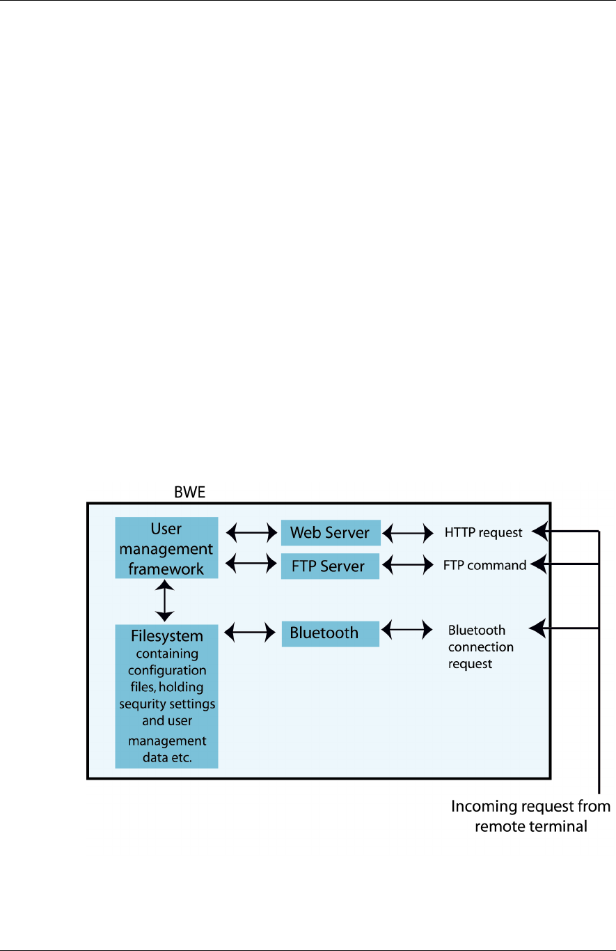
2.7 The security framework in your WNP
Your WNP comes with a framework to manage security and access rights for the
connecting users. The security framework consists of three different parts:
1. Bluetooth security. The first time you connect a new Bluetooth device to your
WNP you will be asked to enter a Passkey. To be granted access to your WNP, the
Chapter 2: Getting started 2.7: The security framework in your WNP
19
Passkey you enter must match the one that is stored in your WNP. The Passkey in
your WNP is configurable (see “Creating your custom configuration”), and in the
pre-installed application it is set to “0000”.
2. Web security. Using the User Management framework in your WNP it is possi-
ble to specify the access level for each user, and what access level that is required
to be granted access to a specific file. The username and password is verified via
the standard HTTP Basic Authentication procedure when a protected web page is
requested. The User Management framework can easily be administered via a web
based user interface, such as the one that is a part of the pre-installed application
in your WNP (see the “User Management” section of the chapter called “The pre-
installed application”). In the security configuration for the pre-installed application
there is a default a default user (User ID: admin, Password: admin1234, Access
Level: 5) and a set of access limits that are placed on the files that handle the user
management functionality.
3. FTP security. (Not implemented yet, now the user name is always admin and
the password is admin1234.)
The following functionality is NOT implemented yet:
The FTP server in your WNP shares its User Management framework with the web
server. Hence the usernames, passwords and access levels are the same when log-
ging in on the FTP server. However, in contrast to accessing files via the web
server, access is not granted per file. Instead it is required that the user logging in
has the highest access level, which is 5. If this requirement is fulfilled, the user is
granted full access to all the files in the file system of your WNP. For further infor-
mation about FTP server in your WNP, see the section called “Accessing the FTP
server”.
The Bluetooth security settings are stored in a configuration file called “blue-
tooth.cfg”, and the User Management data is stored in another configuration file
called “umconfig.txt”.

3.1: Creating you own custom application Chapter 3: How to create your custom WNP application
20
Chapter 3
How to create your custom WNP
application
The previous chapter described how to mount your WNP and how to use the pre-
installed application. In this chapter we present the basic steps in creating your
own WNP application.
By a WNP application we mean a set of configuration files and web pages that are
stored in the file system of your WNP. The configuration files set up your WNP to
match your specific use case and the web pages make up the actual user interface
to your industrial equipment.
3.1 Creating you own custom application
Creating you own custom application typically means performing the following
three steps in sequence:
1. Creating your custom configuration
The configuration files are used to set up your WNP to match the circumstances
under which it shall work in your specific case. This involves specifying IP ad-
dresses, configuring the serial port, setting the default home page, etc. In the
chapter “Creating your custom configuration” there is a thorough description of
how the configuration of your WNP works, along with specifications of all the
configurable parameters.
2. Creating your custom web pages
Once you have created your configuration files, the next step is to make the web
pages that form the user interface to the industrial equipment for which your
WNP was set up. In the chapter “Creating your custom web pages” there is a de-
scription of how to make such web pages for your WNP.
3. Installing your custom application
When the configuration and web page files that make up your application are fin-
ished you must download them to your WNP. This can be done in two ways, ei-
ther via FTP or via a utility called the connectBlue Flash Loader that you will find on
the CD that comes with your WNP. For step-by-step instructions, see the chapter
“Installing your custom application” where both methods are described in detail.

Chapter 4: Creating your custom configuration 4.1: Configuration files
21
Chapter 4
Creating your custom configuration
This chapter describes how to configure your WNP to fit your particular system
setup. It also specifies all the parameters that are configurable in your WNP.
The following parts of your WNP has to be configured:
• Bluetooth
• TCP/IP Networking
• Web server
• Modbus interface (including serial communication settings)
• Logger
• User Management
4.1 Configuration files
The configuration parameters are divided into groups, where each group of pa-
rameters is located in a separate configuration file. The name of each configura-
tion file is predetermined, so that your WNP knows what file to look for. Below is
a summary of the all the configuration files in your WNP:
Configurable component Configuration file name
Bluetooth “bluetooth.cfg”
TCP/IP Networking “network.cfg”
Web server “webserver.cfg”
Modbus interface “modbus.cfg”
Logger “logger.cfg”
User Management “umconfig.txt”
The configuration files themselves are plain ASCII text files, which can be created
and edited in a normal text editor such as Notepad or WordPad for Windows. The
only exception to this rule is the User Management configuration file (“umcon-
fig.txt”), since some of its contents are stored in an encrypted format.

Chapter 4: Creating your custom configuration 4.2: Modbus configuration
22
File format
All configuration files have one or more entries. Each entry specifies the value of a
separate configurable parameter. The syntax of all the entries are of ‘Key =Value’
type. The ‘Key’ uniquely identifies a certain configurable parameter, and the
‘Value’ specifies the value of that parameter.
Each configurable parameter uses a different format for its ‘Value’. Therefore this
format is always specified along with the description of each parameter (see the
section “Parameters in the configuration files”).
It is possible to add comments to your configuration files, in order to ease the un-
derstanding of its content. A line containing a comment starts with a hash sign (#)
and ends with a line feed.
Note: It is very important that you follow the exact format specifications for each
file when you create a new configuration. Otherwise your WNP might have prob-
lems interpreting it, which can result in a faulty or non-expected behavior.
Example showing the format of a configuration file:
#
# connectBlue AB configuration file
#
ExampleKey1 = Value1
ExampleKey2 = Value2
4.2 Modbus configuration
Before your application can access the industrial equipment that your WNP is at-
tached to, the Modbus interface has to be configured.
A part of this configuration consists of making the Modbus registers in the indus-
trial devices visible to your application’s web pages. When your application wants
to access the industrial equipment that is attached to your WNP, it calls a set of
pre-defined functions in a bus interface abstraction layer called the General Bus In-
terface (GBI). The General Bus Interface is described in the following section.
The General Bus Interface (GBI)
The General Bus Interface (GBI) is a generalized interface to any kind of industry
standard bus interface, such as Modbus or Profibus. The idea behind GBI is to pro-
vide a common way of accessing all bus types, without having to worry about their
proprietary techniques and protocols.
Chapter 4: Creating your custom configuration 4.2: Modbus configuration
23
When calling the GBI functions, you always use an Interface Descriptor and an Id
as in-parameters. The Interface Descriptor selects which kind of bus interface to
use, and the Id is an identifier for a specific property or object on a device attached
to the selected bus interface. How the mapping between an Id and a device prop-
erty (such as a Modbus register) is done varies, and it is specific for each kind of
bus interface. To find out how the mapping is done for the Modbus interface, see
the section “Mapping Modbus to GBI”.
Note: Currently the WNP support the following interfaces: Modbus, MMS, and
BMS. However, with the use of the GBI concept the WNP is well prepared if sup-
port for other industry standard bus interfaces is to be added in the future.
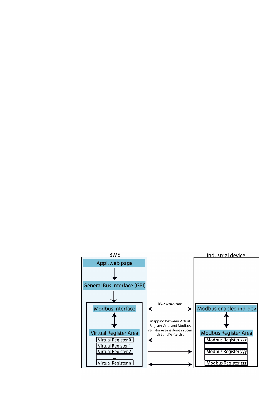
Mapping Modbus to GBI
The natural way to access a Modbus device is to read from and write to a set of
16-bit registers. In order make these registers accessible from the GBI interface (see
section “The General Bus Interface”), it is necessary to map these Modbus registers
to a set of GBI Id:s. This mapping is done in the configuration file for the Modbus
interface (see section “Parameters in the configuration files”, subsection “Mod-
bus”).
In the case with Modbus, your WNP stores all the data in a Virtual Register Area
(see picture below). The register numbers in this Virtual Register Area are used as
the Id parameter when calling GBI functions that access the Modbus interface.
Periodically, the values of the Modbus registers of the attached industrial equip-
ment will be copied to the Virtual Register Area, according to an entry in the Mod-
bus configuration file, called the Scan List (see section “Parameters in the configu-
ration files”, subsection “Modbus”). When your WNP application wants to read a
value from a Modbus device via GBI, it will in fact read from a Virtual Register and
not from a device directly.
Similarly, when writing data to a Virtual Register, the data will propagate to a cor-
responding Modbus register on the industrial equipment that is attached to your
WNP, if this Virtual Register has been mapped in the Write List entry of the Mod-
bus configuration (see section “Parameters in the configuration files”, subsection
“Modbus”).

4.3: Parameters in the configuration files Chapter 4: Creating your custom configuration
24
4.3 Parameters in the configuration files
In this chapter all the configurable parameters in your WNP are described. The
configuration parameters are divided into groups, where each group of parameters
is located in a separate configuration file. For each of these configuration files
there is a separate subsection below describing its contents.
If the entry for a parameter is left out of the configuration file, it will be given a de-
fault value. The default value for each parameter is specified in the summary at the
end of each subsection.
Modbus
This group of configuration parameters is used to configure the Modbus interface
in your WNP. The configuration file that contains these parameters must be
named “modbus.cfg ” in your WNP. Below is a list of all the entries in this con-
figuration file. The key name is written within parenthesis after the parameter
name in the headings below.
Serial Interface (mb_interface)
The
Serial Interface
configuration parameter selects which type of serial interface
to use (RS-232/422/485).
Parity (mb_parity)
The
Parity
configuration parameter sets which type of parity to use.
Stop Bits (mb_stop_bits)
The
Stop Bits
configuration parameter sets the number of stop bits to use.
Baud Rate (mb_baud_rate)
The
Baud Rate
configuration parameter sets which baud rate to use.
Query Response Hold Time (mb_query_response_hold_time)
The
Query Response Hold Time
specifies the time (in number 10 millisecond ticks)
that your WNP shall wait after receiving a response before it may send the next
query. This parameter is only applicable when RS-422/485 is used.
Scan List (mb_scan_list)
The
Scan List
configuration parameter is used to map Modbus registers in your in-
dustrial equipment onto corresponding Virtual Registers in your WNP. Periodically,
your WNP will poll these Modbus registers for their current value by sending Read-
queries to your Modbus devices. The data that is read will then be copied to the
corresponding Virtual Register in your WNP.
The Scan List has the following format: “Entry;Entry2;…;EntryN;”, where each en-
try defines one mapping. The entries contain a list of variables in the format
“Slave,Function,Starting Virtual Register,Scan Period,Starting Slave Regis-
ter,Number Of Registers”. Below is a description of what these variables mean:
Variable Description Valid Value
Slave The Modbus slave that this query shall
be sent to.
[1-255]
Function The Modbus function to use when
sending the query.
1, 2, 3, 4
Starting Virtual Register The Virtual Register where your WNP
shall start to store the data retrieved by
[0..1024]

Chapter 4: Creating your custom configuration 4.3: Parameters in the configuration files
25
this query.
Scan Period The number of seconds between each
refresh of the Virtual Registers
[1..255]
Starting Slave Register The Modbus register address in the
slave where this query shall start to
read from.
[0..65535]
Number of Registers The number of Modbus registers that
shall be read by this query.
[0 ..126]
Note: Some slaves only support a
limited number of registers to be read
in one query-response operation. You
must check how many registers your
certain device supports.
Note: The Scan List may not contain more than 20 entries.
Write List (mb_write_list)
The
Write List
configuration parameter is used to map Modbus registers in your in-
dustrial equipment onto corresponding Virtual Registers in your WNP. It is only
possible for your application to write to Virtual Registers that have been mapped in
the Write List.
When data is written to a Virtual Register in your WNP that has been mapped in
the Write List, a corresponding Modbus Write-query will be sent to one of your
Modbus devices. This query will tell the device to write the data that it receives in
the query to one (or more) of its registers.
The Write List has the following format: “Entry;Entry2;…;EntryN;”, where each en-
try defines one mapping. The entries contain a list of variables in the format
“Slave,Function,Starting Virtual Register,Starting Slave Register,Number Of Regis-
ters”. Below is a description of what these variables mean:
Variable Description Valid val-
ues
Slave The Modbus slave that this query shall be sent to. [1-255]
Function The Modbus function to use when sending the query. 5, 6, 16
Starting Virtual Register The Virtual Register where your WNP shall start to write
the data that will be sent to the slave.
[0..1024]
Starting Slave Register The starting Modbus register address in the slave, where
the data that it receives shall be written.
[0..65535]
Number of Registers The maximum number of registers that can be sent to the
slave when performing a write to the Starting Virtual Reg-
ister in this entry. Note: The actual number of registers
sent will be determined when a GBI write function is
called, however it can never exceed the Number of Regis-
ters specified in this entry.
[0..126]

4.3: Parameters in the configuration files Chapter 4: Creating your custom configuration
26
Note: The Write List may not contain more than 20 entries.
Summary of the entries in the “modbus.cfg” configuration file:
Parameter
name
Key name Valid values Default
value
Serial Interface mb_interface “RS232”, “RS422”,”RS485” RS232
Parity mb_parity “ODD”, ”EVEN”, ”NONE”
ODD
Stop bits mb_stop_bits “1”, ”2” 1
Baud rate mb_baud _rate “110”
“300”
”1200”
”2400”
”4800”
”9600”
”19200”
”38400”
”57600”
”115200”
9600
Query Response
Hold Time
mb_query_response_hold_time [0..100] 0
Scan List mb_scan_list Entry1;Entry2;…;EntryN;
Where each Entry = “Slave,
Function, Starting Virtual Regis-
ter, Scan Period, Starting Slave
Register, Number of Registers;”
None
Write List mb_write_list Entry1;Entry2;…;EntryN;
Where each Entry = “Slave,
Function, Starting Virtual Reg-
ister, Starting Slave Register,
Number Of Registers;”
None

Chapter 4: Creating your custom configuration 4.3: Parameters in the configuration files
27
File example:
#
# Modbus configuration (modbus.cfg)
#
mb_interface =RS232
mb_parity =ODD
mb_baud_rate=19200
mb_stop_bits =1
mb_query_response_hold_time =10
mb_write_list =1,16,1,8000,1;1,16,2,8009,1;
mb_scan_list =1,3,1,1,8000,10;1,3,7,1,8014,7;
Network
This group of configuration parameters is used to configure the TCP/IP Network in-
terface in your WNP. The configuration file that contains these parameters must
be named “network.cfg” in your WNP.
Using DHCP to acquire the TCP/IP network settings
If the WNP is attached to an Ethernet LAN, you can use DHCP to automatically ac-
quire the TCP/IP network settings. Assuming that there is a correctly configured
DHCP server attached to the same LAN, all the network configuration parameters
can be acquired in this way. This includes the parameters for the Default Gateway
and the DNS Server.
The choice to use DHCP or not is made separately for each interface (PPP and
Ethernet). Hence you can for example chose to have statically assigned settings for
the Ethernet interface, and use DHCP to acquire the network settings for the PPP
interface.
If you choose to acquire the network settings for an interface via DHCP, any pa-
rameter values specified for this interface in the configuration file will be ignored.
However, if a parameter is missing in the settings that are sent to your WNP from
the DHCP server, your WNP will fall back to the value that is specified for that pa-
rameter in the network configuration file. If your configuration file doesn’t contain
an entry for that parameter, the default value for the parameter will be used.
If you have selected to use DHCP for the Ethernet interface, but there is no DHCP
server reachable on the LAN, your WNP will perform automatic retries until there is
one that answers. During the time your WNP tries to contact a DHCP server, your
WNP will of course not be reachable from the LAN, since it hasn’t yet acquired its
settings for the Ethernet interface.
If you have selected to use DHCP for the PPP interface, but there is no DHCP server
reachable on the LAN when a Bluetooth enabled client connects to your WNP,
your WNP will perform automatic retries to reach a DHCP server. If no DHCP
server has answered within 15 seconds, your WNP will fall back to using static set-
tings for the PPP interface during this connection.
The local DNS server in your WNP
Your WNP incorporates a local DNS server capable of resolving its own host name,
which by default is “wnp”. The IP address that is returned for this URL is the IP ad-
4.3: Parameters in the configuration files Chapter 4: Creating your custom configuration
28
dress of the network interface of your WNP on which the DNS request arrived.
This is very useful if you connect to your WNP via Bluetooth and you don’t know
what IP address it has. Then you can simply enter “http://wnp” in the address field
of your web browser and press <ENTER>, in order to get to the default web page
of your WNP.
When connecting to your WNP via Bluetooth, the IP address of the local DNS
server in your WNP will be sent to your terminal during the PPP connection estab-
lishment procedure. Hence, if you for example enter an URL in the address field of
the web browser on your terminal and press <ENTER>, a resolve request will be
sent to the local DNS server. If the URL is “http://wnp”, the local DNS server will
successfully resolve it. For all other URL:s the it will forward the request to the ex-
ternal DNS server specified in the network configuration file (or received via DHCP)
and let that DNS server handle the request.
Below is a list of all the entries in this configuration file. The key name is written
within parenthesis after the parameter name in the headings below.
PPP use DHCP (ppp0_use_dhcp)
The
PPP use DHCP
parameter specifies whether or not DHCP is to be used to ac-
quire the settings for the PPP interface.
PPP Local IP Address (ppp0_local_ipaddr)
The
PPP Local IP Address
parameter specifies the IP address for the local side of the
PPP interface in your WNP. By this we mean the IP address that the PPP interface
in your WNP will be given when a client connects via PPP over Bluetooth.
PPP Remote IP Address (ppp0_remote_ipaddr)
The
PPP Remote IP Address
parameter specifies the IP address for the remote side
of the PPP interface in your WNP. By this we mean the IP address that a client will
be given when connecting to your WNP via PPP over Bluetooth.
Ethernet use DHCP (eth0_use_dhcp)
The
Ethernet use DHCP
parameter specifies whether or not DHCP is to be used to
acquire the settings for the Ethernet interface.
Ethernet IP Address (eth0_ ipaddr)
The
Ethernet IP Address
parameter specifies the IP address of the Ethernet inter-
face in your WNP.
Ethernet Subnet Mask (eth0_netmask)

Chapter 4: Creating your custom configuration 4.3: Parameters in the configuration files
29
The
Ethernet Subnet Mask
parameter specifies the subnet mask for the Ethernet
interface in your WNP.
Default Gateway (default_gateway)
The
Default Gateway
parameter specifies the IP address of a Default Gateway to
be used by clients connecting via PPP. This typically is the IP address of a Router on
your Ethernet LAN. The IP address is sent to the clients during the PPP connection
establishment procedure.
DNS Server (dns_server)
The
DNS Server
parameter specifies the IP address of an external DNS server to be
used by clients connecting via PPP.
DNS Host Name (dns_hostname)
The
DNS Host Name
parameter specifies the hostname of your WNP. Clients that
connect via Bluetooth LAN Profile can use this name instead of the IP address
when accessing your WNP, providing their terminal has support for DNS name
resolution. For example the web server of your WNP can be accessed by entering
“http://<hostname>” instead of “http://<ipaddress>” in the address field of the
web browser.
WINS Server (wins_server)
The
WINS Server
parameter specifies the IP address of a WINS server to be used by
clients connecting via PPP. The IP address is sent to the clients during the PPP con-
nection establishment procedure.
Summary of the entries in the “network.cfg” configuration file:
Parameter
name
Key name Valid val-
ues
Default
value
PPP DHCP ppp0_use_dhcp “yes” or “no” “yes”
PPP Local IP Ad-
dress
ppp0_local_ipaddr “xxx.xxx.xxx.xxx” 10.0.0.200
PPP Remote IP Ad-
dress
ppp0_remote_ipaddr “xxx.xxx.xxx.xxx” 10.0.0.201
Ethernet DHCP eth0_use_dhcp “yes” or “no” “yes”
Ethernet IP Address eth0_ ipaddr “xxx.xxx.xxx.xxx” 10.0.0.100
Ethernet Subnet
Mask
eth0_netmask “xxx.xxx.xxx.xxx” 255.255.0.0
Default Gateway default_gateway “xxx.xxx.xxx.xxx” The IP address of
the Ethernet inter-
face, if an
Ethernet interface
is present. Other-
wise no default
gateway will be
used.

4.3: Parameters in the configuration files Chapter 4: Creating your custom configuration
30
DNS Server dns_server ”xxx.xxx.xxx.xxx” If not specified,
DNS won’t be
negotiated during
PPP connection
establishment.
DNS Host Name dns_hostname A valid DNS host
name up to 40
characters long.
“wnp”
WINS Server wins_server “xxx.xxx.xxx.xxx” If not specified,
WINS won’t be
negotiated during
PPP connection
establishment.
File example:
#
# Network configuration (network.cfg)
#
# Common settings
default_gateway = 10.0.0.2
dns_server = 10.0.0.2
dns_hostname = wnp
wins_server = 10.0.0.2
# PPP interface
ppp0_use_dhcp = no
ppp0_local_ipaddr = 10.0.0.200
ppp0_remote_ipaddr = 10.0.0.201
# Ethernet interface
eth0_use_dhcp = no
eth0_ipaddr = 10.0.0.100
eth0_netmask = 255.255.0.0
Bluetooth
This group of configuration parameters is used to configure the Bluetooth inter-
face in your WNP. The configuration file is called “bluetooth.cfg”. Below is a list of
all the entries in this configuration file.
Device Name (bt_local_name)
The
Device Name
specifies a user-friendly name for your WNP to help distinguish it
from other Bluetooth devices in the vicinity.
If you want to include the Bluetooth Device Address of your WNP in its
Device
Name
, you can include the string “%BD_ADDRESS%” in the parameter value.
Your WNP will automatically replace this string with the Bluetooth Device Address
of your WNP when the parameter is set, as shown in the example below.
Example: Assume that the Bluetooth Device Address of your WNP is
0x0000803F8E6A, and you set the
Device Name
to “WNP Unit 28,

Chapter 4: Creating your custom configuration 4.3: Parameters in the configuration files
31
%BD_ADDRESS%”. Then the user-friendly name that will be presented to other
Bluetooth devices is “WNP Unit 28, 0000803F8E6A”.
Passkey (bt_passkey)
The
Passkey
is used to assure that only authorized persons are granted access to
your WNP. When a Bluetooth device connects to your WNP, the user of that de-
vice will be prompted to enter a passkey. The passkey that the user enters must
correspond to the one that is stored in your WNP, or access will be denied. The
Passkey
may contain 1 to 16 characters.
Note: The Bluetooth Passkey authentication mechanism will only be used if
Bluetooth security mode 3 is turned on in your WNP.
Security Mode (bt_security_mode3)
The
Security Mode
parameter is used to turn Bluetooth security mode 3 on or off.
If it is turned on, this will require users connecting to your WNP to enter a Passkey
on their terminal in order to be granted access. For some PAN devices to be able to
connect to this device this parameter must be set to “on”.
LAN Access Service Name (bt_lan_service_name)
The
LAN Access Service Name
parameter specifies the name of the LAN Access
service in your WNP. When remote Bluetooth units discover the services of your
WNP, this user-friendly name will be used to present the LAN Access service.
PAN role (bt_pan_role)
This parameter specifies if the device is NAP or PANU. If the device is NAP,
then it can connect to the devices that are specified with the
bt_pan_remote_peers parameter. Other devices can also connect to this de-
vice and access the network services.
If the device has the role as PANU, then it can only have one connection,
because it is always slave.
PAN NAP service name (bt_pan_nap_service_name)
This parameter can be set if the default name of the service shall be changed.
PAN PANU service name (bt_pan_panu_service_name)
This parameter can be set if the default name of the service shall be changed.
PAN remote peers (bt_pan_remote_peers)
This parameter shall be set if an Ethernet bridge shall be setup between this device
and one or several PANU devices. Make sure that this device is configured as a
NAP device. When this device starts it will try to connect to all the peers specified
in this list.
Terminal server remote peers (bt_ts_remote_peers)
This parameter shall be set if terminal server is required. Up to seven remote peers
can be configured.
Field bus configuration (bt_fieldbus_type, bt_fieldbus_baudrate,
bt_fieldbus_databits, bt_fieldbus_stopbits, bt_fieldbus_parity,
bt_fieldbus_flowcontrol)
These parameters can be set to change the default values of the field bus. The val-
ues will be discarded if the WNP is set up to use the field bus for other communi-
cation such as modbus or bms.

4.3: Parameters in the configuration files Chapter 4: Creating your custom configuration
32
Summary of the entries in the Bluetooth configuration file:
Parameter
name
Key name Valid values Default value
Local Name bt_local_name Up to 80 characters
Access Point
Passkey bt_passkey 1 to 16 characters
[A..Z][a..z][0..9]
0000
Security Mode bt_security_mode3 “on” or “off” “off”
LAN Access
Service Name
bt_lan_service_name Up to 100 charac-
ters
“LAN Service”
PAN role bt_pan_role “NAP” or “PANU” “NAP”
PAN NAP Ser-
vice Name
bt_pan_nap_service_
name
Up to 100 charac-
ters
“NAP Service”
PAN PANU Ser-
vice Name
bt_pan_panu_service
_name
Up to 100 charac-
ters
“PANU Service”
Remote PANU
servers
bt_pan_remote_peers “{}”
Remote TS serv-
ers
bt_ts_remote_peers “{}”
Field bus type bt_fieldbus_type “RS232”,
“RS422”, “RS485”
“RS232”
Baud rate bt_fieldbus_baudrate “9600”, ”19200”,
“38400”, ”57600”,
”115200”,
”230400”,
“460800”
“9600”
Data bits bt_fieldbus_databits “5”, “6”, “7”, “8” “8”
Stop bits bt_fieldbus_stopbits “1”, “2” “1”
Parity bt_fieldbus_parity “NONE”, “ODD”,
“EVEN”
“NONE”
Flow control bt_fieldbus_flowcont
rol
“CTS/RTS”,
“NONE”
“NONE”
File example:
# Bluetooth configuration
bt_local_name = My Bluetooth device

Chapter 4: Creating your custom configuration 4.3: Parameters in the configuration files
33
bt_passkey = 0000
bt_security_mode3 = on
bt_spp_service_name = SPP Service
#bt_lan_service_name = LAN Service
# PAN role to use (NAP or PANU)
bt_pan_role = NAP
#bt_pan_nap_service_name = NAP Service
#bt_pan_panu_service_name = PANU Service
#Remote panu servers
bt_pan_remote_peers =
{
00:12:F3:00:9A:05
0012f3009a06
}
#Remote terminal server peers
#”Bluetooth address”%”port number”
bt_ts_remote_peers =
{
00:12:F3:00:9A:05%2000
0012f3009a06%2001
}
#Field bus configuration
#bt_fieldbus_type = RS232
#bt_fieldbus_baudrate = 9600
#bt_fieldbus_databits = 8
#bt_fieldbus_stopbits = 1
#bt_fieldbus_parity = NONE
#bt_fieldbus_flowcontrol = CTS/RTS
Web Server
The configuration file is called “webserver.cfg ”.
Default Home Page (ws_default_home_page)
This parameter is used to set the default home page of the web server in your
WNP. The default home page may be up to 20 characters long, which is the
maximum file name length in your WNP.
Summary of the entries in the web server configuration file:
Parameter
name
Key name Valid val-
ues
Default
value
Default home
page
ws_default_home_page Up to 20 charac-
ters
index.html
File example
#
# Webserver configuration (webserver.cfg)
#
ws_default_home_page =index.html
Logger

4.3: Parameters in the configuration files Chapter 4: Creating your custom configuration
34
This group of configuration parameters is used to configure the logger in your
WNP. The configuration file that contains these parameters must be named “log-
ger.cfg ” in your WNP. Below is a list of all the entries in this configuration file.
The key name is written within parenthesis after the parameter name in the head-
ings below.
Note: The Logger collects its data via the General Bus Interface (GBI). For a de-
scription of this interface, see the section “The General Bus Interface”.
Log List (logger_log_list)
This parameter specifies which data from the industrial equipment to log.
The
Log List
has the following format: “Entry;Entry2;…;EntryN;”, where each entry
defines one GBI ID to log from a certain bus interface. The entries contain a list of
variables in the format “Interface Descriptor,ID,Data Type,Hysteresis,Ring Buffer
Number,Bit Number”. Below is a description of what these variables mean:
Variable Description Valid values
Interface Descriptor The GBI bus interface type to use. 1
ID The GBI ID to log on the selected bus
interface.
Bus specific
Data Type The data type that shall be logged. Bit, I1Bit, I2Bit,
I4Bit, I1, UI1, I2,
UI2, I4, UI4
Hysteresis To actually be logged, the currently
polled value must differ by at least the
Hysteresis from the previously logged
value for this entry. The Hysteresis vari-
able only applies if the data type used is
I1, UI1, I2, UI2, I4 or UI4.
For the other data types the currently
polled value will always be logged if it
differs from the previously logged value
for this entry (no hysteresis used).
Example: Data Type = UI2, Hysteresis
= 200
Comment
Polled value nr 1 = 3428
First value is always logged
Polled value nr 2 = 3571
|3428-3571| = 143 <= 200 (Hysteresis)
=> Value not logged
Polled value nr 3 = 3112
|3428-3112| = 316 > 200 (Hysteresis) =>
Value logged
[0..2147483647]
Ring Buffer Number In which ring buffer shall the logged
value be stored?
0,1

Chapter 4: Creating your custom configuration 4.3: Parameters in the configuration files
35
Bit Number This variable is only applicable if the
data type used is I1Bit, I2Bit or I4Bit. In
this case the logger will read an 1, 2 or 4
byte integer from the selected GBI ID,
and if the bit Bit Number in the integer
has changed from its previously logged
value, the new value will be logged.
For other data types this variable is ig-
nored.
[0..7] for I1Bit
[0..15] for I2Bit
[0..31] for I4Bit
Log Period (logger_log_period)
This parameter determines how often the entries in the Log List shall be polled for
their value. The period is specified in number of seconds, and it is common for all
entries in the
Log List
.
Ring Buffer 0 (logger_ring_buffer_0)
The logger has two ring buffers that are used to store the entries that are logged.
The
Ring Buffer 0
parameter value uses the following format: “Ring Buffer
Size,Number of Backup Files”. The Ring Buffer Size variable specifies the number
of entries that the ring buffer can store. The Number of Backup Files variable speci-
fies the number of backup files used for the ring buffer.
When an entry is stored in the ring buffer, the logger starts writing from the be-
ginning of the ring buffer, and then continuously adds new entries until the end is
reached. At the point when the end is reached, the logger will first save the entries
in the ring buffer to a backup file in the file system (providing the ring buffer has
been configured to use backup files). Then the logger will start writing at the be-
ginning of the buffer again, thereby overwriting the oldest entry.
Depending on how many backup files are used the following will happen when a
ring buffer gets full, before the logger starts writing over old entries in the ring
buffer.
Number of
backup files
Action taken when the ring buffer gets full
0 No action will be taken. The logger will start writing over old
entries immediately.
1 The entries in the ring buffer will be stored in backup file on the
file system named “logbackup0_1.txt”. If a previous backup file
named “logbackup0_1.txt” exists, it will be overwritten.
2 The entries in the ring buffer will be stored in backup file on the
file system named “logbackup0_1.txt”. If a previous backup file
named “logbackup0_1.txt” exists, it will first be renamed to
“logbackup0_2.txt”. If a previous backup file named “log-
backup0_2.txt” exists, it will be overwritten.
For each entry logged in the ring buffer the GBI Interface Descriptor, GBI ID and a
Time Stamp is stored. The format of the backup files is the same as that used
when the ASP script function “aspDumpLogToFile()” is called. See chapter “Creat-

4.3: Parameters in the configuration files Chapter 4: Creating your custom configuration
36
ing your custom web pages”, section “ASP script functions”, sub section “Log-
ger”.
Ring Buffer 1 (logger_ring_buffer_1)
See description of the “Ring Buffer 0” parameter. The only difference is that the
backup files used are named “logbackup1_1.txt” and “logbackup1_2.txt” instead
of “logbackup0_1.txt” and ““logbackup0_2.txt” respectively.
Summary of the entries in the logger configuration file:
Parameter
name
Key name Valid values Default
value
Log List logger_log_list Entry1;Entry2;…;EntryN;
Where each Entry = “In-
terface Descrip-
tor,ID,Data
Type,Hysteresis,Ring
Buffer Number,Bit Num-
ber”
None
Log Period logger_log_period [1.. 4294967295] 1
Ring Buffer 0 logger_ring_buffer_0 [1..1000],[0,1,2] 500,0
Ring Buffer 1 logger_ring_buffer_1 [1..1000],[0,1,2] 500,0
File example:
#
# Logger configuration (logger.cfg)
#
logger_log_list = 1,64,Bit,0,0,0;1,0,UI1,100,0,0;
logger_log_period = 4
logger_ring_buffer_0 = 100,0
logger_ring_buffer_1 = 500,2
User Management
To configure the User Management framework in your WNP, it is recommended
that you use the User Management web pages that are a part of the pre-installed
default application. Feel free to modify them as you like in order to make them
match the visual design of your own custom application.
It is not recommended that you manually alter the contents of the User Manage-
ment configuration file named “umconfig.txt”. One of the reasons for this is that
the password of a user is stored in an encrypted format in order to keep it secret
from the other users on your WNP. Hence, it must be read and written by the
software in your WNP, which is able to encrypt and decrypt the passwords stored
in the User Management configuration file.

Chapter 5: Creating your custom web pages 5.1: ASP scripts
37
Chapter 5
Creating your custom web pages
The web pages stored in your WNP form the actual user interface to your indus-
trial equipment. These web pages have the ability to include data, such as a tem-
perature or speed measurement, that has been collected from the devices in the
network to which your WNP is attached. It is also possible to set parameters in the
devices from the web interface. In order the manage those tasks the web server in-
side the WNP contains functionality to handle dynamic behavior on web pages.
The web server comes from a company called GoAhead. It’s especially created to
run in embedded systems with limited CPU and memory resources. This means
that it is designed to be very efficient and sparse in its memory requirements. Still,
in contrast to a lot of other embedded web servers, the GoAhead web server has a
framework to create dynamic content that is very easy to learn and use. Much of
this is due to the fact that it uses the well-known standard techniques ASP and
JavaScript, while many other embedded web servers rely on proprietary solutions
to create dynamic content.
For a description of which parts of ASP and JavaScript are supported in the GoA-
head web server, please visit http://www.goahead.com . Follow the links that di-
rect you to the GoAhead webserver. There you’ll also find an online documenta-
tion and a functionality overview.
5.1 ASP scripts
To insert ASP scripts in a web page, the script code must be encapsulated between
the special tags “<%” and “%>”. A web page containing script code must also
have an “.asp” extension in the filename so that the web server can distinguish it
from normal HTML pages.
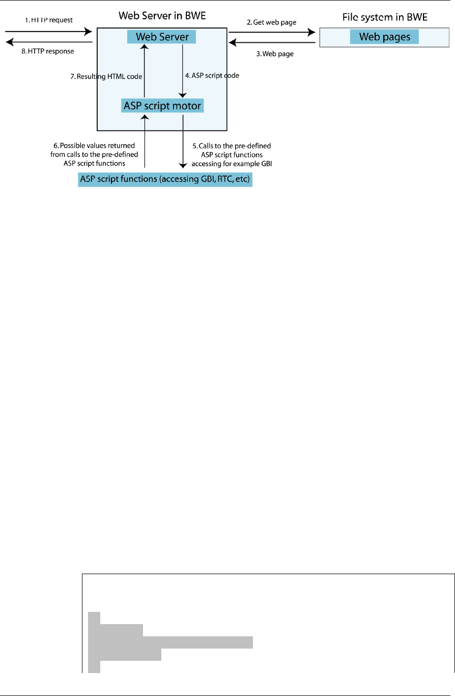
When the web server receives a HTTP request for an ASP web page, it will get the
web page from the file system and then scan through it looking for script sections.
Whenever the web server detects a script section, it will cut this section out of the
web page and send it to the ASP script motor that evaluates the script code. The
evaluation of the script code can involve calls to the pre-defined ASP functions in
your WNP that are used for example to access the GBI interface. If the script code
returns any resulting HTML code, this will be inserted into the web page in the
place where the script code originally was. When all script sections in the ASP web
page have been processed, the resulting web page is returned to the client’s web
browser in a HTTP response.
5.1: ASP scripts Chapter 5: Creating your custom web pages
38
Commands in the GoAhead's JavaScript Inter-
preter
• Variables and variable declarations (var)
• Global functions with support for local JavaScript variables
• If, then, else
• For loops
• Expressions including: + - / * % ++ -- | & || && << >> < <= == > >=
• Statements: return, braces, comma, semicolon
• Comments
Missing from the embedded implementation are arrays, objects, regular expres-
sions and object methods. The resulting implementation is a 15K Embedded
JavaScript interpreter that is highly tuned to the needs of embedded devices,
rather than a 200K conventional memory footprint.
Below are two typical examples of how script code can be used.
Example1: Present data in a web page
This is an example where dynamic data that is read from a device is incorporated in
a web page. Here we use the ASP script function
aspGBIReadI2
to retrieve a tem-
perature value from a fictive device to which the WNP is supposed to be attached.
The ASP script functions that your WNP supports are described in the section “ASP
script functions”.
“temperature.asp”
<HTML>
<BODY>
Current Temperature =
<%
var Temp;
Temp = aspGBIReadI2(1, 14);
write(Temp);
%>

Chapter 5: Creating your custom web pages 5.1: ASP scripts
39
</BODY>
</HTML>
When the web server has processed this ASP web page, the following result will be
returned to the client’s web browser (assuming the read temperature was 57 de-
grees).
<HTML>
<BODY>
Current Temperature = 57
</BODY>
</HTML>
Example2: Set a device parameter
In this example we set a device parameter according to a value that is entered by
the user. This is typically performed in a three-step process.
1. The first step consists of the user requesting a web page containing a HTML
form, where the new parameter value can be entered:
“speed_form.html”
<HTML>
<BODY>
<FORM action=”set_new_speed.asp”>
Please enter new speed: <INPUT type=”text” name=”new_speed”>
<INPUT type=”submit” value=”Set Speed”>
</FORM>
</BODY>
</HTML>
2. In the second step the user views the web page above, enters the new speed
value, and presses the [Set Speed] button. This will trigger his web browser to send
a request for the web page “set_new_speed.asp”. The new speed value is sent
along with the request, as a CGI variable with the name “new_speed”.
3. When the web server receives the request for “set_new_speed.asp”, it detects
that a CGI variable is sent along with the request. This variable (new_speed) and its
value is extracted by the web server, and made available to the script code in the
web page that is requested. We use this to call a script function that passes along
the variable value to a fictive device. Here’s what is might look like:
”set_new_speed.asp”
<HTML>
<BODY>
<%
aspGBIWriteI2(1, 14, new_speed);
%>
The new speed was successfully set to <%write(new_speed);%>!
</BODY>
</HTML>
When the web server processes this web page, it will call the script function
aspGBIWriteI2
with the “new_speed” variable as input parameter. This function
will make the WNP send a message to a certain device telling it to set its speed pa-
rameter to the value of “new_speed”. The second script section,

5.2: ASP script functions Chapter 5: Creating your custom web pages
40
“<%write(new_speed);%>”, is used to include the value of “new_speed” in the
web page.
Finally, the processed web page will be returned to the client’s web browser, in-
forming that the operation was successful. Here’s what it would look like, if the
user had entered 1200 as the new speed value:
<HTML>
<BODY>
The new speed was successfully set to 1200!
</BODY>
</HTML>
5.2 ASP script functions
This section describes the predefined ASP functions that your WNP supports.
These functions can be called from the script sections of your ASP web pages. They
perform operations that use the primary functionality of your WNP, such as ac-
cessing registers on a Modbus device that is attached to your WNP or setting your
WNP’s system time. Please note that these functions have been added to the
GoAhead web server by connectBlue, and that they are especially designed for the
WNP. Therefore you won’t find any information about these functions on the
GoAhead website.
General functions
This section describes the ASP functions that handle general tasks that don’t be-
long to any special function category. Typically these functions perform utility op-
erations such as extracting the value of a CGI variable.
string aspVarExists(variableName)
Description: Checks if a web server or CGI variable with the name variable-
Name exists.
In-parameters:
Parameter Description Valid values
variableName The name of the variable to
check for.
A variable name that may
exist.
Return value: If the variable exists, 1 is returned. Otherwise 0 is returned.
string aspGetVar(variableName)
Description: Extracts the value of the web server or CGI variable with the name
variableName.

Chapter 5: Creating your custom web pages 5.2: ASP script functions
41
In-parameters:
Parameter Description Valid values
variableName The name of the variable
whose value shall be ex-
tracted.
The name of an existing web
server or CGI variable
Return value: The value of the selected variable is returned as a string.
string aspAND(valueA, valueB)
Description: Returns the result of the bit-wise logical operation “valueA AND
valueB”. Both the input parameters and the return value are 32-bit signed inte-
gers, specified as decimal numbers (for example 1035482 or –124691).
In-parameters: valueA and valueB are the values that the AND operation is per-
formed on.
Return value: The result of the bit-wise logical operation “valueA AND valueB”.
string aspOR(valueA, valueB)
Description: Returns the result of the bit-wise logical operation “valueA OR val-
ueB”. Both the input parameters and the return value are 32-bit signed integers,
specified as decimal numbers (for example 1035482 or –124691).
In-parameters: valueA and valueB are the values that the OR operation is per-
formed on.
Return value: The result of the bit-wise logical operation “valueA OR valueB”.
string aspXOR(valueA, valueB)
Description: Returns the result of the bit-wise logical operation “valueA XOR
valueB”. Both the input parameters and the return value are 32-bit signed inte-
gers, specified as decimal numbers (for example 1035482 or –124691).
In-parameters: valueA and valueB are the values that the XOR operation is per-
formed on.
Return value: The result of the bit-wise logical operation “valueA XOR valueB”.
string aspWaitTime(waitTime)
Description: Halts the processing of the current web page for waitTime millisec-
onds before continuing.
In-parameters:
Parameter Description Valid values
waitTime The number of milliseconds to
wait before the processing of
the web page is resumed.
[0..4294967295]

5.2: ASP script functions Chapter 5: Creating your custom web pages
42
Return value: This function doesn’t have a return value.
string aspGetFirmwareVersion()
Description: Returns a string specifying the firmware version of your WNP.
In-parameters: This function doesn’t have any in-parameter.
Return value: A string specifying the firmware version of your WNP is returned.
string aspGetSystemStatus()
Description: Returns the current system status of your WNP.
In-parameters: This function doesn’t have any in-parameter.
Return value: The current system status is returned as string holding a status code.
Below is a list of the status codes that can be returned:
Status
code
Meaning
0 Invalid status code (Error).
1 Your WNP is starting up.
2 Your WNP hasn’t been able to receive its IP settings for the
Ethernet interface from a DHCP server on the LAN yet
3 Your WNP is powered on, has started up and is working cor-
rectly.
4 Your WNP is in the process of establishing a Bluetooth link.
5 Your WNP is connected to another device via a Bluetooth link.
6 Your WNP has detected a recoverable error that must be attended
to.
7 Your WNP has detected an irrecoverable error.
string aspResetSystem(timeout)
Description: This function will trigger a system reset after timeout milliseconds.
The reset operation is asynchronous, so the web server will continue its operation
after this function has been called until the system reset actually is performed. This
makes it possible to set a timeout that long enough for the web server to be able
to return the contents of the web page that triggered the reset operation to the
client.

Chapter 5: Creating your custom web pages 5.2: ASP script functions
43
In-parameters:
Parameter Description Valid
values
timeout The number of milliseconds to wait before
the web server triggers the reset.
[0..30000]
Return value: This function doesn’t have a return value.
Configuration Manager
The Configuration Manager is a part of your WNP that handles the configuration
of the different components that your WNP is built up of (such as Bluetooth and
the web server). Using the ASP function that accesses the Configuration Manager
you can retrieve the settings for these components, in order to for example include
them in a status web page. Note that with aspCMSetKeyValue and aspCMGet-
KeyValues it is possible to configure all parameters in the configuration files, see
chapter “Creating your custom configuration”, section ”Parameters in the con-
figuration files”.
string aspCMAvailable(cfgFileName)
Description: This function checks whether a file exists in the WNP’s file system.
In-parameters:
Parameter Description Valid val-
ues
cfgFileName The name of the file. Any string
Return value: The function returns “OK” if the file exists.
string aspCMGetKeyValue(cfgFileName, key)
Description: This function returns the value of a key in a file. The syntax in the file
could for example be: bt_local_name = MyDevice
The key is the string to the left of the equal sign and the value is the string to the
right.
Parameter Description Valid val-
ues
cfgFileName T he name of an existing file. Use
aspCMAvailable to check if the file
exists.
A string
key The name of the variable to retrieve.
A string
Return value: The function returns the value of the key.
string aspCMSetKeyValue(cfgFileName, key,
value)

5.2: ASP script functions Chapter 5: Creating your custom web pages
44
Description: This function writes a value to a file. If the key already exists, then the
value will be replaced. If the key doesn’t exist, then the key will be added to the
file.
Parameter Description Valid
values
cfgFileName The name of an existing file. Use
aspCMAvailable to check if the file exists.
A string
key The name of the variable to retrieve. A string
Value The value to be written in the file. A string
Return value: The function returns “OK” if the call succeeded.
string aspCMGetParam(componentId, parame-
terId)
Description: This function returns the value of a certain setting for a selected com-
ponent.
Parameter Description Valid values
componentId
Selects which component to ac-
cess
See table below.
parameterId Specifies which parameter from
the selected component to get.
See table below.
componentId selects which component to access, see the table below.
Component
Name
Component ID Notes
Network 1
Smtp 2 Currently not acces-
sible
Logger 3 Currently not acces-
sible
Modbus 4 Currently not acces-
sible
FTP 5 Currently not acces-
sible
Web server 6
Bluetooth 7
parameterId specifies which parameter from the selected component to get, see
the tables below.

Chapter 5: Creating your custom web pages 5.2: ASP script functions
45
Network
Parameter Name Parameter ID
Loopback interface IP address 1
Loopback interface net mask 2
Ethernet interface IP address 3
Ethernet interface subnet mask 4
Ethernet interface broadcast address 5
Ethernet interface MAC/hardware address 6
PPP interface local IP address 7
PPP interface remote IP address 8
PPP interface subnet mask 9
Default gateway IP address 10
DNS server IP address 11
Web server
Parameter Name Parameter ID
Default home page 1
Bluetooth
Parameter Name Parameter ID
Bluetooth local name 1
Bluetooth passkey 2
Return value: The value of the selected parameter is returned as a string.
Example: aspCMGetParam(7, 2) will return your WNP’s Bluetooth passkey.
Note: When trying to retrieve the value of a parameter that currently is not avail-
able from the Network component, a space character (“ “) will be returned. This
happens for example if you try to get the remote IP address of the PPP interface
when no active PPP connection exists.
General Bus Interface (GBI)
This section describes the ASP functions used to access the General Bus Interface
(GBI) which is described in chapter “Creating your custom configuration”, section
“The General Bus Interface”. It’s important that you have configured the bus inter-
face you want to access correctly before calling these functions.
Note1: Some of these functions that read or write integers come in three different
versions. Each version works with a different integer size (1, 2 or 4 bytes). The dif-

5.2: ASP script functions Chapter 5: Creating your custom web pages
46
ferent versions are recognized by two letters in the function name (I1, I2 or I4) in-
dicating which integer size they use.
Note2: Some of these functions use floating-point numbers. When this data type
is being used, numbers must be specified as decimal numbers, for example
“34.189” or “-0.00822”. Hence, the functions will not accept formats such as
“323E+9” or “7541E-2”.
string aspGBIReadBit(interfaceDescriptor, id)
Description: Reads the status of a bit from GBI.
Parameter Description Valid val-
ues
interfaceDescriptor Selects which bus interface to use. 1
id A bus specific identifier specifying
which object or property to read from
Bus specific
Return value: If successfully executed, the status is returned as a string with the
value 0 or 1. Otherwise the string “ERROR” is returned.
string aspGBIWriteBit(interfaceDescriptor, id,
dataBit)
Description: Writes the status of a bit to GBI.
Parameter Description Valid val-
ues
interfaceDescriptor Selects which bus interface to use.
1
id A bus interface specific identifier that
specifies which object or property to
write to.
Bus specific
dataBit The value of the bit to be written 0 or 1
Return value: If successfully executed, the string “OK” is returned. Otherwise “ER-
ROR” is returned.
string aspGBIReadStr(interfaceDescriptor, id,
strLen)
Description: Reads a string from GBI.
In-parameters:
Parameter Description Valid val-
ues
interfaceDescriptor Selects which bus interface to use. 1

Chapter 5: Creating your custom web pages 5.2: ASP script functions
47
id A bus interface specific identifier that
specifies which object or property to
read from.
Bus specific
strLen The number of characters to be read. [0..80]
Return value: If successfully executed, the string that was read from GBI is re-
turned. Otherwise the string “ERROR” is returned.
Remarks: If “strLen” is set to the value “0”, the whole string will be read, until the
string-terminating null-character is reached. However, if the string is longer than
80 characters, it will be truncated.
string aspGBIWriteStr(interfaceDescriptor, id,
“textStr”)
Description: Writes a text string to GBI.
Parameter Description Valid val-
ues
interfaceDescriptor Selects which bus interface to use. 1
id A bus specific identifier specifying
which object or property to write to.
Bus specific
textStr The string to be written. Up to 80 charac-
ters
Return value: If successfully executed, the string “OK” is returned. Otherwise “ER-
ROR” is returned.
string aspGBIReadI1(interfaceDescriptor, id)
string aspGBIReadI2(interfaceDescriptor, id)
string aspGBIReadI4(interfaceDescriptor, id)
Description: Reads an integer from GBI.
Parameter Description Valid val-
ues
interfaceDescriptor Selects which bus interface to use. 1
id A bus specific identifier specifying
which object or property to read from.
Bus specific
Return value: If successfully executed, the value of the read integer is returned as a
string. Otherwise the string “ERROR” is returned.

5.2: ASP script functions Chapter 5: Creating your custom web pages
48
string aspGBIWriteI1(interfaceDescriptor, id, in-
tegerData)
string aspGBIWriteI2(interfaceDescriptor, id, in-
tegerData)
string aspGBIWriteI4(interfaceDescriptor, id, in-
tegerData)
Description: Writes an integer to GBI.
Parameter Description Valid values
interfaceDescriptor Selects which bus inter-
face to use.
1
id A bus specific identifier
specifying which object
or property to write to.
Bus specific
integerData The value of the integer
to be written.
[-128..127] for integer size 1
[-32768..32767] for integer size 2
[-2147483648..2147483647] for
integer size I4
Return value: If successfully executed, the string “OK” is returned. Otherwise “ER-
ROR” is returned.
string aspGBIReadI1Dec(interfaceDescriptor, id,
nrDecimals)
string aspGBIReadI2Dec(interfaceDescriptor, id,
nrDecimals)
string aspGBIReadI4Dec(interfaceDescriptor, id,
nrDecimals)
Description: Reads an integer from GBI, converts it to a floating-point number, di-
vides the float by 10 ^ nrDecimals, and returns the result.
Parameter Description Valid val-
ues
interfaceDescriptor Selects which bus interface to use. 1
id A bus specific identifier specifying
which object or property to read from.
Bus specific
nrDecimals The number of decimals to use. [-10..10]

Chapter 5: Creating your custom web pages 5.2: ASP script functions
49
Return value: If successfully executed, the resulting floating-point number is re-
turned as a string. Otherwise the string “ERROR” is returned.
Example: Integer data read from GBI =38423, nrDecimals =3 =>The floating-
point number “38.423” is returned.
string aspGBIWriteI1Dec(interfaceDescriptor, id,
“floatData”, nrDecimals)
string aspGBIWriteI2Dec(interfaceDescriptor, id,
“floatData”, nrDecimals)
string aspGBIWriteI4Dec(interfaceDescriptor, id,
“floatData”, nrDecimals)
Description: Multiplies the floating-point number stored in floatData with
10^nrDecimals, converts the result to an integer which then is written to GBI.
In-parameters:
Parameter Description Valid val-
ues
interfaceDescriptor Selects which bus interface to use. 1
id A bus specific identifier specifying
which object or property to rwrite to.
Bus specific
floatData The floating-point number to be written. A floating-point
number
nrDecimals The number of decimals to use. [-10..10]
Return value: If successfully executed, the string “OK” is returned. Otherwise “ER-
ROR” is returned.
Remarks: Please note that the resulting integer that is to be written to GBI must fit
within the boundaries of the selected integer size (I1, I2 or I4). These boundaries
are presented below:
Integer size Boundaries
I1 [-128..127]
I2 [-32768..32767]
I4 [-2147483648..2147483647]
Example: floatData =38.423, nrDecimals =2 => The integer 3842 is written to
GBI.

5.2: ASP script functions Chapter 5: Creating your custom web pages
50
string aspGBIReadI1Scale(interfaceDescriptor,
id, “minVal”, “maxVal”, nrDecimals)
string aspGBIReadI2Scale(interfaceDescriptor,
id, “minVal”, “maxVal”, nrDecimals)
string aspGBIReadI4Scale(interfaceDescriptor,
id, “minVal”, “maxVal”, nrDecimals)
Description: Reads an integer from GBI and maps/scales it to a floating-point num-
ber, which is returned. The floating-point number will be within the range min-
Val to maxVal.
In-parameters:
Parameter Description Valid val-
ues
interfaceDescriptor Selects which bus interface to use. 1
id A bus specific identifier specifying
which object or property to read from.
Bus specific
minval The lowest point on the floating-point
scale.
A floating-point
number
maxval The highest point on the floating-point
scale.
A floating-point
number
decimalPrecision The number of decimals to be used for
the return value.
[-10..10]
Return value: If successfully executed, the resulting floating-point number is re-
turned as a string. Otherwise the string “ERROR” is returned.
string aspGBIWriteI1Scale(interfaceDescriptor,
id, “minVal”, “maxVal”, “floatData”)
string aspGBIWriteI2Scale(interfaceDescriptor,
id, “minVal”, “maxVal”, “floatData”)
string aspGBIWriteI4Scale(interfaceDescriptor,
id, “minVal”, “maxVal”, “floatData”)
Description: Maps/scales the floating-point number stored in floatData to an in-
teger. The float number must be within the range minVal to maxVal.
Parameter Description Valid values
interfaceDescriptor Selects which bus interface to use. 1

Chapter 5: Creating your custom web pages 5.2: ASP script functions
51
id A bus specific identifier specifying
which object or property to write to.
Bus specific
minval The lowest point on the floating-point
scale.
A floating-point
number
maxval The highest point on the floating-point
scale.
A floating-point
number
floatData The floating-point number to be writ-
ten.
[minVal..maxVal]
Return value: If successfully executed, the string “OK” is returned. Otherwise “ER-
ROR” is returned.
string aspGBIReadI1Time(interfaceDescriptor,
id)
string aspGBIReadI2Time(interfaceDescriptor,
id)
string aspGBIReadI4Time(interfaceDescriptor,
id)
Description: Reads an integer from GBI holding a time value specified in number of
seconds, and then converts it to a string in the format “hh:mm:ss ” which is re-
turned.
Parameter Description Valid val-
ues
interfaceDescriptor Selects which bus interface to use. 1
id A bus specific identifier specifying
which object or property to read from.
Bus specific
Return value: If successfully executed, the time is returned as a string in the format
“hh:mm:ss”. Otherwise the string “ERROR” is returned.
string aspGBIWriteI1Time(interfaceDescriptor,
id, ”time”)
string aspGBIWriteI2Time(interfaceDescriptor,
id, ”time”)
string aspGBIWriteI4Time(interfaceDescriptor,
id, ”time”)

5.2: ASP script functions Chapter 5: Creating your custom web pages
52
Description: Converts the string time specified in the format “hh:mm:ss” to num-
ber of seconds and then writes this as an integer to GBI.
Parameter Description Valid val-
ues
interfaceDescriptor Selects which bus interface to use. 1
id A bus specific identifier specifying
which object or property to write to.
Bus specific
time A string holding the time to be written. hh:mm:ss
Return value: If successfully executed, the string “OK” is returned. Otherwise “ER-
ROR” is returned.
Remarks: Please note that the resulting integer that is to be written to GBI must fit
within the boundaries of the selected integer size (I1, I2 or I4). These boundaries
are presented below:
Integer size Boundaries
I1 [-128..127]
I2 [-32768..32767]
I4 [-2147483648..2147483647]
Real Time Clock
This chapter describes the functions used to access the Real Time Clock (RTC) in
your WNP. Using these functions, you can set and get the date and time of your
WNP.
string aspRTCGetTime()
Description: Returns the current time of the RTC in your WNP as a string with the
format “hh:mm:ss”.
In-parameters: This function doesn’t have any in-parameter.
Return value: If successfully executed, this function returns the current time of the
RTC in your WNP as a string with the format “hh:mm:ss”. If the power to the RTC
has been lost, the string “Power lost” is returned. If a general error in the RTC has
been detected “ERROR” is returned.
string aspRTCSetTime(“time”)
Description: Sets the time of the RTC in your WNP according to the time string,
specified in the format “hh:mm:ss”.
Parameter Description Valid values
time A string holding the time which
the RTC shall be set to.
[0..23]:[0..59]:[0..59]

Chapter 5: Creating your custom web pages 5.2: ASP script functions
53
Return value: If successfully executed, the string “OK” is returned. Otherwise “ER-
ROR” is returned.
string aspRTCGetDate()
Description: Returns the current date of the RTC in your WNP as a string with the
format “20yy/mm/dd”.
In-parameters: This function doesn’t have any in-parameter.
Return value: If successfully executed, this function returns the current date of the
RTC in your WNP is returned as a string with the format “20yy/mm/dd”. If the
power to the RTC has been lost, the string “Power lost” is returned. If a general
error in the RTC has been detected the “ERROR” is returned.
string aspRTCSetDate(“date”)
Description: Sets the date of the RTC in your WNP according to the date string,
specified in the format “20yy/mm/dd”.
Parameter Description Valid values
time A string holding the date
which the RTC shall be set
to.
[2000..2037]/[1..12]/[1..31]
Return value: If successfully executed, the string “OK” is returned. Otherwise “ER-
ROR” is returned.
Logger
string aspDumpLogToFile(“filename”, ring-
BufferNumber)
Description: Dumps the entries currently stored in one of the Logger’s ring-buffers
to a file.
In-parameters:
Parameter Description Valid val-
ues
filename The name of the file to which the Log-
ger entries shall be written.
Up to 20 charac-
ters
ringBufferNumber The number of the ring buffer that
contains the entries to be stored.
1,2
Return value: This function doesn’t have a return value.
Remarks: The log file that is created as a result of calling this function contains a
list of log entries. Each entry is placed on a separate line, and consists of a comma-
separated list of variables in the following format “Interface Descriptor,ID,

5.2: ASP script functions Chapter 5: Creating your custom web pages
54
Type,Value,Time Stamp”. Below you find a description of what these variables
mean:
Variable Description posible
values
Interface Descrip-
tor
The GBI bus interface where this log
entry comes from.
1
ID The GBI ID that has been logged in this
entry.
Bus specific
Type The data type for the Value in this log
entry.
Bit, I1Bit, I2Bit,
I4Bit, I1, UI1, I2,
UI2, I4, UI4
Value The value that has been logged in this
entry.
Depends on the
Type for this
entry.
Time Stamp A timestamp specifying when this Value
was logged.
yy/mm/dd
hh:mm:ss
Example: Here is an example of what a log file might look like:
1,124,I2,32177,03/05/24 14:48:47
1,124,I2,112,03/05/24 14:49:16
1,130,Bit,HIGH,03/06/12 02:52:33
1,80,I4Bit,HIGH,03/06/12 05:49:59
Note: Since the logger uses a ring buffer that wraps around when it gets full, the
entries in the log file are not guaranteed to be in chronological order.
User Management
To access the User Management framework in your WNP, it is recommended that
you use the User Management web pages that are a part of the pre-installed de-
fault application. Feel free to modify them as you like in order to make them
match the visual design of your own custom application.
Black Board
This chapter describes Black Board component, which can write and read data to a
RAM buffer. It’s also possible to store the data to flash with the two functions de-
scribed below. Use the page testPage.txt in the default file system to get ac-
quainted with the component.
The Black Board is a GBI interface which has the GBI id number 6. It is a byte
buffer which contains 8192 bytes. It’s possible to access these bytes with the fol-
lowing asp code:
var id = “6”; // This number refers to Black Board.
var gbiVar = “4”; // This number points to a byte in the byte array.
result = aspGBIWriteI1(id, gbiVar, value);
result = aspGBIWriteI2(id, gbiVar, value);
result = aspGBIWriteI4(id, gbiVar, value);

Chapter 5: Creating your custom web pages 5.2: ASP script functions
55
result = aspGBIWriteF4(id, gbiVar, value);
result = aspGBIWriteStr(id, gbiVar, value);
value = aspGBIReadI1(id, gbiVar);
value = aspGBIReadI2(id, gbiVar);
value = aspGBIReadI4(id, gbiVar);
value = aspGBIReadF4(id, gbiVar);
value = aspGBIReadStr(id, gbiVar);
Note that the byte array is byte oriented! Do the following to write two 4-byte
integers:
result = aspGBIWriteI4(6, 0, theInt);
result = aspGBIWriteI4(6, 4, theOtherInt);
It’s possible to use Black Board to convert an int to a float:
result = aspGBIWriteI4(6, 0, value);
value = aspGBIReadF4(6, 0);
It’s also possible to save the contents to and from flash:
aspBLACKBOARDSave("settings.txt");
aspBLACKBOARDLoad("settings.txt");
See descriptions below.
string aspBLACKBOARDSave(fileName)
Description: Used for saving BlackBoard’s RAM buffer to flash.
In-parameters: filename is the name of the file, e.g. “mySettings.txt”
Return value: Return value: If successfully executed, the string “OK” is returned.
Otherwise “ERROR” is returned.
string aspBLACKBOARDSave(fileName)
Description: Used for loading BlackBoard’s RAM buffer from flash.
In-parameters: filename is the name of the file, e.g. “mySettings.txt”
Return value: If successfully executed, the string “OK” is returned. Otherwise “ER-
ROR” is returned.

6.1: Installing file system using FTP Chapter 6: Installing your custom application
56
Chapter 6
Installing your custom application
When you have created your application, you have to install the configuration files
and web pages that it consists of in your WNP.
Before you install a new application, please take some time to check your configu-
ration files once again, since an invalid configuration file might put your WNP in
an error state. If your WNP ends up in an error state where it can’t be reached via
the Bluetooth or Ethernet interface, debug the configuration files and then install
the application files again.
6.1 Installing file system using FTP
This section describes the general steps you need to perform if you want to install
your application using an FTP client. Since every FTP client has its own user inter-
face, the exact procedure will differ somewhat depending on which one you de-
cide to use. Please turn to the manual for your specific FTP client for information
on how a certain step is performed.
To install your application files using FTP, follow the procedure below:
1. Use an FTP client on your PC to establish a connection to the FTP server in your
WNP. For example: Windows Explorer or WS_FTP LE or WS_FTP Home.
2. Logon with the ip address of your device, 10.0.0.100 as default, and the user-
name “admin” and password “admin1234”.
3. Use your FTP client to send your application files to the FTP server in your WNP.
The FTP server will store the files it receives in the file system of your WNP. If a
file with the same name already exists in your WNP, the new one that is re-
ceived via FTP will replace it.
4. Disconnect your FTP client from the FTP server in your WNP.
5. Reset your WNP by unplugging the power cable, and then plugging it in again.
This will activate your new application. If all goes well, the Status LED of your
WNP will become green.
6.2 Installing file system using the serial
port
See the chapter about Upgrading file system via the serial port.

Chapter 7: Firmware upgrade 7.1: Serial upgrade
57
Chapter 7
Firmware upgrade
There are two ways to upgrade the FW. It can either be done via a serial cable or
via the network. The device can always be configured via the serial interface even
when the device is configured wrong. In order to upgrade the FW via the network
the network connections must work via Ethernet or Bluetooth.
7.1 Serial upgrade
This upgrade is done via the serial port in the DSUB.
Upgrading firmware via the serial port
1. Install the program “connectBlue Flash Loader”. Open the program by press-
ing “Start->Programs->connectBlue->Flash Loader->Flash Loader”.
2. Choose any Product/Platform. This choice doesn’t matter for this product!
3. Select application file by pressing the button with “three dots” to the right of
the drop down list. The application file shall be the bin-file that represents the
firmware.
4. Select correct com port.
5. Press “Load” and wait until the status bar is finished.
6. Wait for your device to restart itself. You do not need to restart it manually!
If your device doesn’t start it might have the wrong firmware and then you can
just flash it again with the correct firmware.
Upgrading the file system via the serial port
The WNP contains a number of configuration files and web pages, which control
the behavior of the WNP. If the configuration files becomes faulty or if the WNP
for some reason doesn’t start it might be necessary to reflash all files in the filesys-
tem.
Do the same as described for upgrading firmware above, but instead of using the
firmware release you shall use a bin file which contains both the firmware and the
file system. Do the following to retrieve such a file.
1. Use an FTP client on your PC to establish a connection to the FTP server in your
WNP. For example: WS_FTP LE, WS_FTP Home or the Windows native FTP Cli-
ent. NOTE: The FTP Client must be able to retrieve a file from the FTP server
which doesn’t exist when listing all files.
2. Logon with the ip address of your device, 10.0.0.100 as default, and the
username “admin” and password “admin1234”.
3. Retrieve the file “imageAndFileSystem.bin”. In WS_FTP you do this by pressing
the arrow pointing to the left without marking any file and then enter the file
name in the dialog box that pops up.

7.2: Network upgrade Chapter 7: Firmware upgrade
58
4. Now you can use this file to flash another WNP to get the same settings.
7.2 Network upgrade
This upgrade of the firmware can be done either via the Ethernet network or via
Bluetooth.
1. Rename the binary firmware file to “image.bin”.
2. Connect the WNP with an FTP client. The default static ip address is
10.0.0.100. Username is “admin” and password is “admin1234”.
3. Download the image.bin file to the WNP.
4. Close the FTP connection.
5. Wait for the device to reset itself. Do not restart it manually!
If the device doesn’t start again or if it keeps restarting, then something has went
wrong and you must reflash it via the serial port in the DSUB. See instructions for
serial upgrade.

Chapter 8: Regulatory information 8.1: Declaration of conformity
59
Chapter 8
Regulatory information
8.1 Declaration of conformity
We, connectBlue AB, of
Norra Vallgatan 64 3V
SE-211 22 Malmö, Sweden
declare under our sole responsibility that our products:
Wireless Network Platform (cB-3013-01, cB-3021-01, cB-3022-01, cB-3023-01, cB-
3024-01, cB-3025-01 and cB-3026-01)
to which this declaration relates, conforms to the following product specifications:
R&TTE Directive 1999/5/EC
EN 300 328 V1.6.1 (2004-11)
EMC Directive: 89/336/EEC
EN 61000-6-2 (2001)
EN 61000-6-4 (2001)
01/03/2006 Malmö, Sweden
Mats Andersson
CTO of connectBlue AB
More information at:
http://europa.eu.int/comm/enterprise/rtte/gener.htm

8.2: FCC Statement Chapter 8: Regulatory information
60
8.2 FCC Statement
This device complies with Part 15 of the FCC Rules. Operation is subject to the fol-
lowing two conditions: (1) this device may not cause harmful interference, and (2)
this device must accept any interference received, including interference that may
cause undesired operation.
NOTE: This equipment has been tested and found to comply with the limits for a
Class B digital device, pursuant to Part 15 of the FCC Rules. These limits are de-
signed to provide reasonable protection against harmful interference in a residen-
tial installation. This equipment generates, uses and can radiate radio frequency
energy and, if not installed and used in accordance with the instructions, may
cause harmful interference to radio communications. However, there is no guaran-
tee that interference will not occur in a particular installation. If this equipment
does cause harmful interference to radio or television reception, which can be de-
termined by turning the equipment off and on, the user is encouraged to try to
correct the interference by one or more of the following measures:
• Reorient or relocate the receiving antenna
• Increase the separation between the equipment and receiver
• Connect the equipment into an outlet on a circuit different from that to
which the receiver is connected
Consult the dealer or an experienced radio/TV technician for help
Antenna
The end-user product will be professionally installed in such a manner that only the
authorized antennas are used.
Caution
Any changes or modifications NOT explicitly APPROVED by connectBlue AB could
cause the module to cease to comply with FCC rules part 15, and thus void the
user’s authority to operate the equipment.
8.3 IC Compliance
Operation is subject to the following two conditions:
(1) this device may not cause harmful interference, and
(2) this device must accept any interference received,
including interference that may cause undesired operation.
This device has been designed to operate with an antenna having a maximum gain
of 8.5dBi.
Having a higher gain is strictly prohibited per regulations of Industry Canada. The
required antenna impedance is 50 ohms.
To reduce potential radio interference to other users, the antenna type and its gain
should be so chosen that the equivalent isotropically radiated power (EIRP) is not
more than that required for successful communication.
The installer of this radio equipment must ensure that the antenna is located or
pointed such that it does not emit RF field in excess of Health Canada limits for the

Chapter 8: Regulatory information 8.4: Safety
61
general population; consult Safety Code 6, obtainable from Health Canada’s web-
site www.hc-sc.gc.ca/rpb.
8.4 Safety
The unit must be supplied by a limited power source in according to EN 60950-1.
8.5 RF-exposure Statement
This modular transmitter MUST have a separation distance of at least 20 cm be-
tween the antenna and the body of the user or nearby persons, excluding hands,
wrists, feet, and ankles.
If the radio module is installed in a laptop display, transmission MUST be prevented
if the lid is closed to ensure that the minimum distance of 20 cm between the user
and the transmitting antenna is maintained.
Any notification to the end user of installation or removal instructions about the in-
tegrated radio module is NOT allowed.
8.6 UL listing information
If a customer intends to UL list a product including any of the Bluetooth modules
based on the PCB cB-0901-03 this information is useful:
The printed circuit board if produced according to the following specification:
• UL recognized ZPMV2 min. 105 °C flame class V-0 or better.
8.7 Compliance with RoHS directive
All products are produced according to the RoHS (Restriction of the use of certain
Hazardous substances in electrical and electronic equipment) directive and com-
plies with the directive.

8.8: Bluetooth Qualification information Chapter 8: Regulatory information
62
8.8 Bluetooth Qualification information
Table 1 - Bluetooth Qualification information
Module Bluetooth specifica-
tion
Bluetooth identi-
fier
Qualification date
cB-3013-01, cB-3021-
01, cB-3022-01, cB-
3023-01, cB-3024-01,
cB-3025-01 and cB-
3026-01
2.0 B03088 2006-04-24
The following Bluetooth profiles are supported (covered functionality):
• Generic Access Profile (GAP)
• Serial Port Profile (SPP)
• Personal Area Networking Profile (PAN)
• LAN Access Profile
When creating end products based on the Bluetooth Web Enabler the following
applies:
• The end product does not have to be re-qualified.
• The end product or the end product documentation based on:
o cB-3013-01, cB-3021-01, cB-3022-01, cB-3023-01, cB-3024-01, cB-
3025-01 and cB-3026-01 products shall make the following informa-
tion available: “This product contains a Bluetooth qualified product
QPLN B03088”.
• The Bluetooth Trademark may be placed on the end product (requires Blue-
tooth SIG membership, for more information see www.bluetooth.org).
• The Bluetooth Trademark may be used in material related to the end product
(requires Bluetooth SIG membership, for more information see
www.bluetooth.org).
For more information please contact connectBlue.

Chapter 9: Additional information 9.1: Troubleshooting
63
Chapter 9
Additional information
9.1 Troubleshooting
This section describes the solutions to some of the most common problems. For
additional information see the FAQ (Frequently Asked Questions) for the WNP on
connectBlue’s website www.connectblue.se .
1. I can’t connect to my WNP using Bluetooth:
i. Make sure that you indeed are trying to connect to your WNP and not an-
other Bluetooth device. This can be done by checking the Bluetooth Local
Name and the Bluetooth Device Address of the device you are trying to con-
nect.
ii. If your WNP, or the Bluetooth device you use to connect to your WNP, re-
quire authentication, make sure that the same passkey is used on both de-
vices.
iii. If your WNP, or the Bluetooth device you use to connect to your WNP, re-
quire authentication, make sure that both devices support pairing.
2. I can’t establish a TCP/IP connection to my WNP:
i. Review the TCP/IP settings on your WNP, by checking the TCP/IP networking
configuration file.
ii. Review your TCP/IP network settings on the device you use when trying to
connect to your WNP.
3. I can’t access the web pages in my WNP:
i. Make sure you are connected to your WNP.
ii. Make sure you have entered the correct URL.
iii. Make sure that the web page you are trying to access actually is stored in
your WNP. You can do this by logging in with an FTP client and view the
contents of your WNP’s file system.
iv. Review the TCP/IP settings on your WNP, by checking the TCP/IP networking
configuration file.
v. Review your TCP/IP network settings on the device you use when trying to
connect to your WNP.
4. My WNP can’t communicate with units on the Modbus network to which it is
attached:
i. Make sure that the RX and TX pins are correctly mounted on the cable at-
taching your WNP to the Modbus network. See the chapter “Getting
started”.

9.2: Guidelines for efficient and safe use Chapter 9: Additional information
64
ii. Make sure your Modbus configuration is correct by checking the Modbus
configuration file, see the chapter “Creating your custom configuration”.
iii. Make sure the Modbus unit you are trying to communicate with accepts the
Modbus query packet size that your WNP sends to it. Some Modbus units
only support small Modbus packet sizes.
5. The status LED of my WNP is red, and I can’t access it:
A serious error has been encountered. Try the following in order:
i. Restart your WNP.
ii. If the color of the status LED is still red, check the format and contents of
your configuration files. If you find any error, fix them and then install the
corrected configuration files using the Flash Loader utility, as described in
the section “Installing your custom application”.
9.2 Guidelines for efficient and safe use
Important: Read this information before using your WNP.
For any exceptions, due to national requirements or limitations, when using your
WNP, please visit
www.bluetooth.com
.
Product Care
• Do not expose your product to liquid or moisture.
• Do not expose you product to extreme hot or cold temperature (see “Techni-
cal Specification” for further information).
• Do not expose your product to lit candles, cigarettes, cigars, open flames, etc.
• Do not drop, throw or try to bend your product since rough treatment could
damage it.
• Do not paint your product as the paint could prevent normal use.
• If you will not be using your product for a while, store it in a place that is dry,
free from damp, dust and extreme heat and cold.
Radio Frequency Exposure
Your WNP contains a small radio transmitter and receiver. During communication
with other Bluetooth products your WNP receives and transmits radio frequency
(RF) electromagnetic fields (microwaves) in the frequency range 2400 to 2500
MHz. The output power of the radio transmitter is very low, 0.001 Watt (1 mW).
When using your WNP you will be exposed to some of the transmitted RF energy.
This exposure is well below the prescribed limits in all national and international RF
safety standards and regulations.
Electronic Equipment
Most modern electronic equipment (for example in hospitals and cars) is shielded
from RF Energy. However, certain electronic equipment is not. Therefore:

Chapter 9: Additional information 9.3: Important information
65
Note: This equipment emits RF energy in the ISM (Industrial, Scientific, Medical)
band. Please insure that all medical devices used in proximity to this device meet
appropriate susceptibility specifications for this type of RF energy.
Potentially Explosive Atmospheres
Do not turn on or off your electronic device when in any area with potentially ex-
plosive atmosphere. It is rare, but your electronic device could generate sparks.
Sparks in such areas could cause an explosion or fire resulting in bodily injury or
even death. Areas with a potentially explosive atmosphere are often, but not al-
ways, clearly marked. They include fuelling areas, such as petrol station, below
deck on boats, fuel or chemical transfer or storage facilities, and areas where the
air contains chemicals or particles, such as grain, dust, or metal powders.
Power Supply
• Only connect your power supply to designated power sources as marked on
the product.
• Make sure all cords and cables are positioned so that they will not be stepped
on, tripped over or otherwise subject to damage or stress.
• To reduce risk of electric shock, unplug the unit from any power source before
attempting to clean it.
9.3 Important information
Important: Changes or modifications not expressly approved by connectBlue AB
will void the user’s authority to operate the equipment.
9.4 Technical specification
Bluetooth Interface
Supported Bluetooth Profiles: General Access Profile, Serial Port Profile, LAN Access
Profile, PAN Profile
Bluetooth radio: Up to 20 dBm power output.
Range (line of sight): Up to 150 meters.
Bluetooth Qualification
The product is Bluetooth qualified according to the Bluetooth 2.0 specification.
Serial Interface
Serial connector: Standard male RS-232/422/485 9-pin DSUB connector.
Supported bit rates: 300 – 460 800 bits/second.
Flow control for RS-232: CTS/RTS or none.
Flow control for RS-422/485: None.

9.4: Technical specification Chapter 9: Additional information
66
Power/current consumption
Power connector: Power connector for industrial use.
Power supply: 9-30 V DC.
Power consumption: TBD
File system
The file system in your WNP has 1 MB available for data storage. Filenames may
consist of up to 20 characters. Directories are supported.
Configuration Files
A set of configuration files stored in the file system of your WNP are used to con-
figure:
• Modbus
• TCP/IP Networking
• Bluetooth
• Web server
• Logger
• Security/User Management
Compatibility
The FTP server in your WNP has been tested successfully with the following FTP cli-
ents in both passive and active mode:
• Windows 2000 DOS FTP client
• Windows 2000 Windows Explorer
• Windows XP Windows Explorer
• WS_FTP LE
• FTP Commander 7.33
The Flash Loader utility (on your WNP product CD) is compatible with the follow-
ing platforms:
• Windows 2000
• Windows ME
• Windows XP
Environmental
IP 20

Chapter 9: Additional information 9.4: Technical specification
67
Operating temperature: -30 to +85 °C
Storage temperature: -40 to +85 °C
Humidity: 5-90% RH (non-condensing)