u blox Malmo 0941 Wireless Communication System Module User Manual Electrical and Mechanical Datasheet
u-blox Malmo AB Wireless Communication System Module Electrical and Mechanical Datasheet
Contents
- 1. Electrical and Mechanical Datasheet
- 2. Electrical and Mechaniocal Datasheet
- 3. Users Manual
- 4. Antenna Guide
- 5. User Manual
Electrical and Mechanical Datasheet

connectBlue
Copyright © 2010 connectBlue AB Page 1 of 34
CB-0941-02 (OWS451 AND OWL253) ELECTRICAL
AND MECHANICAL DATASHEET
Document Revision
Release: 16 May, 2011 10:39
Document version: 77
Copyright © 2010 connectBlue AB. The contents of this document can be changed by connectBlue AB without prior notice and do not
constitute any binding undertakings from connectBlue AB. connectBlue AB is not responsible under any circumstances for direct, indirect,
unexpected damage or consequent damage that is caused by this document. All rights reserved. All brand and product names are
trademarks or service marks of their respective owners.

connectBlue
Copyright © 2010 connectBlue AB Page 2 of 34
1 Table of Content
1 Table of Content
2 Introduction
2.1 Key features
2.2 Product variants
2.3 Block diagram
3 Electrical interface and connectors
3.1 Pin numbering
3.2 Pin description
3.3 Characteristics
3.4 Hardware Reset
3.5 Power Control
4 Antenna Information
4.1 Surface mounted antenna (internal)
4.2 External antennas
4.3 Antenna accessories
4.4 Antennas
5 Mounting information
5.1 Module dimensions
5.2 Using the J2/J3 board-to-board connectors
5.3 Using press-fit nuts for mounting
5.4 Recommended M2 screw
5.5 Antenna issues
6 WLAN information
6.1 Radio sensitivity OFDM
6.2 Radio sensitivity DSSS
7 Regulatory information
7.1 Declaration of conformity
7.2 IC and FCC compliance
7.3 UL listing information
7.4 Compliance with RoHS directive
8 Guidelines for efficient and safe use
8.1 General
8.2 Product care
8.3 Radio frequency exposure
8.4 Electronic equipment
8.5 Potentially explosive atmospheres
8.6 Safety compliance
9 Design examples
9.1 Basic design
connectBlue
Copyright © 2010 connectBlue AB Page 3 of 34
2 Introduction
The IEEE 802.11abgn OEM Modules from connectBlue has been developed for integration in industrial devices. The modules are
providing state of the art low power features, compatibility, robustness, and reliability. The modules minimizes the work needed to
implement IEEE 802.11 in a device as it provides, together with the driver package, all software, hardware, type approval, EMC
certification etc. It is developed for reliable, high demanding industrial devices and applications and delivers high performance. The
connectBlue wireless LAN modules are available in different versions (see Product variants).
The wireless LAN modules are complete IEEE 802.11 implementations. The IEEE 802.11 modules has small form factors and the
interface layout is the same as the Bluetooth and IEEE 802.15.4 modules from connectBlue, which enables customers to prepare their
device for both wireless LAN, IEEE 802.15.4, and Bluetooth.
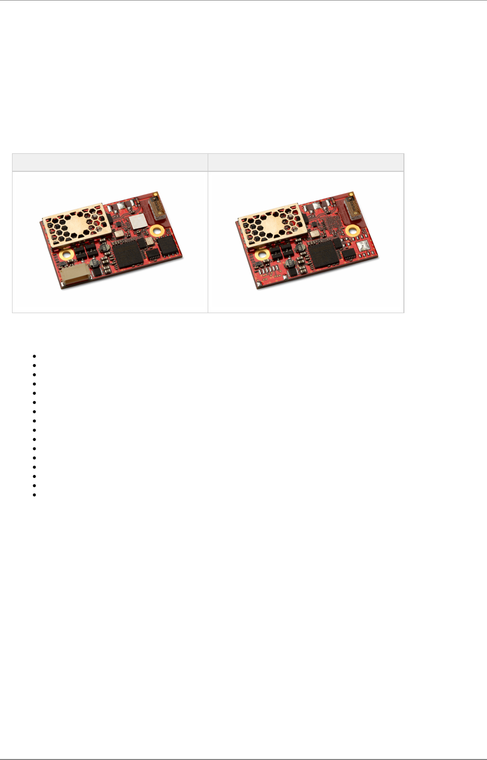
cB-0941-02 (OWS451i-06) cB-0941-02 (OWL253i-04)
2.1 Key features
Dual-band operation (IEEE 802.11-2007, abg, incl. single stream IEEE 802.11n)
WEP, AES, and CRC-32 hardware accelerators
WPA and WPA2 support - both personal and enterprise modes
UART host interface
SPI host interface
Quality of Service: 802.11e and WMM
Ad-hoc and infrastructure mode
Bluetooth co-location with PTA (Packet Traffic Arbitration) support
Radio type approved for Europe.
Unlicensed Modular Transmitter Approval for US (FCC) and Canada (IC).
Compliant with EMC standards.
Industrial temperature range -40 to +85 °C.
Support for low power modes.
Compatible with connectBlue Bluetooth and IEEE 802.15.4 modules
Internal or external antenna
Receive diversity

connectBlue
Copyright © 2010 connectBlue AB Page 4 of 34
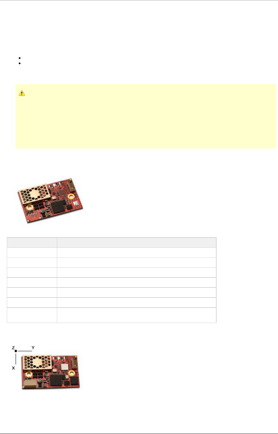
2.2 Product variants
This electrical & mechanical data sheet is applicable to the following wireless LAN modules from connectBlue:
cB-0941-02
The different mounting options of cB-0941-02 hardware (OWS451i/x -04/06 and OWL253i/x-04) are all based on the same PCB.
The module is Type Approved and referred in this document with the model name cB-0941-02.
Model
Family Mounting
option FCC ID IC Description
cB-0941-02 OWL253i-04 PVH0941 5325A-0941 IEEE802.11abgn LAN module with internal antenna, board-to-board
connector, solder-lands, high-speed SPI host interface
cB-0941-02 OWL253x-04 PVH0941 5325A-0941 IEEE802.11abgn LAN module with dual external antenna U.FL. connectors,
board-to-board connector, solder-lands, high-speed SPI host interface
cB-0941-02 OWS451i-04 PVH0941 5325A-0941 IEEE802.11abgn Serial Port Adapter module with internal antenna,
board-to-board connector, solder-lands, UART host interface
cB-0941-02 OWS451x-04 PVH0941 5325A-0941 IEEE802.11abgn Serial Port Adapter module with dual external antenna U.FL.
connectors, board-to-board connector, solder-lands, UART host interface
cB-0941-02 OWS451i-06 PVH0941 5325A-0941 IEEE802.11abgn Serial Port Adapter module with internal antenna,
board-to-board connector, solder-lands, JST connector, UART host interface
cB-0941-02 OWS451x-06 PVH0941 5325A-0941 IEEE802.11abgn Serial Port Adapter module with dual external antenna U.FL.
connectors, board-to-board connector, solder-lands, JST connector, UART
host interface
connectBlue
Copyright © 2010 connectBlue AB Page 5 of 34
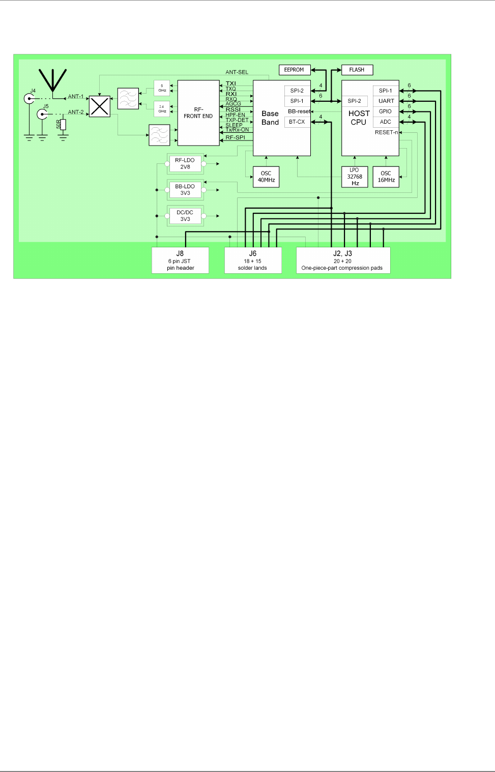
2.3 Block diagram
connectBlue
Copyright © 2010 connectBlue AB Page 6 of 34
3 Electrical interface and connectors
This section describes the signals available on the module interface connectors. There are three ways of connecting:
Via the PCB solder lands on the edge of the PCB, J6 (see figure below: Secondary side connectors). For more information see
Section J6 Solder Lands Description.
Via the 2 x 20-pin 1mm pitch board-to-board (one piece part) connectors J2 and J3. The J2 and J3 connectors exist on the
module only as compression pads (see figure below: Secondary side connectors). These pads mates with the carrier board
one-piece part connector. For more information see Section J2 Connector Description and J3 Connector Description.
Optional:
Via the JST connector, J8 (see figure below: Primary side connectors). The connector is a 6 poles pin header. The pitch is 1mm
and the connector is from JST with part number SM06B-SRSS-TB. For more information see section J8 Connector Description.
3.1 Pin numbering
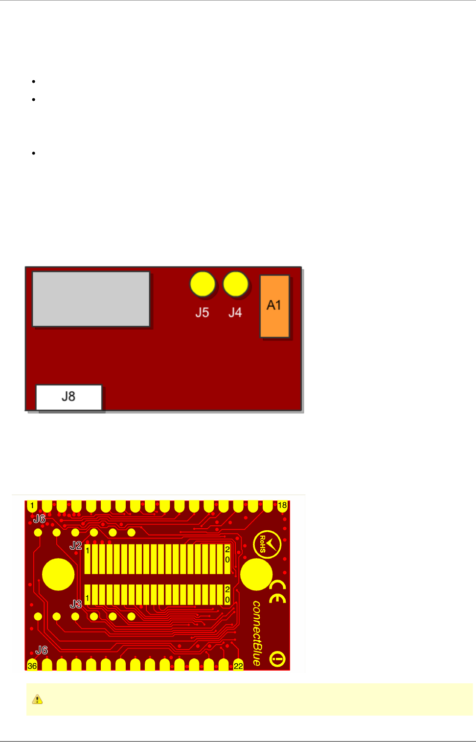
3.1.1 Primary side connectors
J8 is the JST connector located on the primary side of the module. A1 is the internal antenna.
J4 and J5 are U.FL connectors for external antennas. J4 is the primary antenna connector and J5 the auxiliary antenna connector.
3.1.2 Secondary side connectors
J2 and J3 is the connectBlue board-to-board connector. The pin layout of the connector is compatible with all OEM Serial Port Adapters
from connectBlue.
The J6 is the solder land connector.
The solder lands of connector (J6) have a new layout compared to cB-OWSPA311g.

connectBlue
Copyright © 2010 connectBlue AB Page 7 of 34
3.2 Pin description
3.2.1 J2, J3, J6, J8 connector description
J2
Pin
Nr
J3
Pin
Nr
J6
Pin
Nr
J8
Pin
Nr
Signal Name Signal
Level Type Description
1,2 8 3,
25*** 1 VSS Ground Power GND
3,4 - 4 2 VCC 3.3 V Power 3.3 - 5.5 VDC power supply
11 - 7 RED/Mode CMOS Out/In This signal is multiplexed:
RED: red LED logic signal valid 600ms after power-up (see the
section), active low. Operating status
Mode: Mode signal is valid as input only during the first 600ms after
startup, after that its fuction changes to red LED.
The Mode pin is active low with internal weak pull-up
12 - 6 Switch-0 CMOS In Used for the "Connect on external signal" function, see the Serial Port
Adapter AT command Specification for more information on the
Function switch,
active low. The Switch-0 pin has internal weak pull-up
A secondary function is that the module will restore all factory settings if
both the Switch-1 and Switch-0 signals are low during start up.
See the Serial Port Adapter AT command Specification for more
information on the Restoring Default Configuration functionality.
See section for design examples.Switch-0 Signal
13 - 8 GREEN/
Switch-1 CMOS Out/In This signal is multiplexed:
GREEN: gren-LED logic signal valid 500ms after power-up (see the
section), active low. Operating status
Switch-1: Switch-1 signal is valid as input only during the first 500ms
after power-up, after that its fuction changes to green-LED.
If this pin is pulled-down** the unit goes back to default serial settings.
The Switch-1 signal is active low with internal weak pull-up
The module will restore all factory settings if both the Switch-1 and
Switch-0 signals are pulled-down during power-up.
See the Serial Port Adapter AT command Specification for more
information on the Restoring Default Configuration functionality.
See section for design examplesGREEN/Switch-1
14 - 9 5 BLUE CMOS Out Logic Blue LED Signal (see the section).Operating status, table 9
Active low.
Note:Blue LED will flash when data is transfered.
See section for design examples.BLUE Signal
15 - 10 5 UART-CTS* CMOS In Logic level UART Clear To Send, active low.
16 - 11 3 UART-TxD* CMOS Out Logic level UART Transmit Data, "0" = Low, "1" = High
17 - 12 6 UART-RTS* CMOS Out Logic level UART Request To Send, active low.
18 - 13 4 UART-RxD* CMOS In Logic level UART Receive Data, "0" = Low, "1" = High
19 - 5 - UART-DTR* CMOS Out Logic level UART Data Terminal Ready, active low.
20 - 18,
30*** - UART-DSR* CMOS In Logic level UART Data Set Ready, active low.
6 28 - SPI-CS0n CMOS In Logic level SPI chip select, active low.
7 27 - SPI-MOSI CMOS In Logic level SPI Master Output Slave Input
9 36 - SerialSelect-0 CMOS Out Control signal for external serial transceivers.
See section for more info.Appendix Serial Interface
connectBlue
Copyright © 2010 connectBlue AB Page 8 of 34
1.
10 35 - SerialSelect-1 CMOS Out Control signal for external serial transceivers.
See section for more info.Appendix Serial Interface
11 26 - SPI-CLK CMOS In Logic level SPI Clk input
- 13 24 - SPI-MISO CMOS Out Logic level SPI Master Input Slave Output
- 14 23 - SPI-Int CMOS In Logic level SPI external interupt.
- 19 1 - Reset-n CMOS In Hardware reset. Active low.
internal 100k ohm pull-up
- 20 2 - VCC-3V 3.0 V Out Regulated interface voltage for voltage level shifting, max 10mA.
5 -
10 1 -
5,
12,
15 -
18
14 -
17,
19 -
21,
29,
31 -
34
- Reserved, do not connect.
*** Alternative signal pin recommended to use in new designs (both signal pins should be connected).
Logic level signals are CMOS logic level (-0.3V < VIL < 0.8V, 2.3V < VIH < 3.3V).
3.2.2 J4 Primary external antenna connector
J4 is the primary external antenna connector. It is used for both transmit and receive. The port impedance to match is 50 ohm.
J4 pin nr Pin name Signal level Type Description
1 Ant-1 RF I/O Primary external antenna port (50 ohm)
This connector is only available on OWS451x and OWL253x.
3.2.3 J5 Auxiliary external antenna connector
J5 is the auxiliary external antenna connector. It is used only for receiving and if the unit is configured for receive diversity mode. The unit
never transmits RF through this antenna connector. The port impedance to match is 50 ohm.
J5 pin nr Pin name Signal level Type Description
1 Ant-1 RF I Auxiliary external antenna port (50 ohm)
This connector is only available on OWS451x and OWL253x.
UART signals are CMOS logic level (-0.3V < VIL < 0.9V, 2.1V < VIH < 3.3V)

connectBlue
Copyright © 2010 connectBlue AB Page 9 of 34
3.3 Characteristics
The cB-0941-02 family is designed to be fully interchangeable with the connectBlue Bluetooth product range. If the host product has
space for the board, it is possible to choose freely between Bluetooth modules, e.g. cB-OEMSPA311i/x or cB-OEMSPA331i/x, or WLAN
modules, e.g. OWSPA311gi/x, without any change of the host product. If you design your power supply for OWS451i/x the modules will
be fully interchangeable.
3.3.1 Power supply
Read the safety notes in section Guidelines for Efficient and Safe Use before using the modules.
3.3.1.1 Supply voltage
Symbol Parameter Min Typ. Max Unit
VDD Supply voltage 3.3 5.5 V
connectBlue
Copyright © 2010 connectBlue AB Page 10 of 34
3.3.1.2 Current consumption
3.3.1.2.1 cB-0941-02 (OWS451)
Symbol Power Mode State Band DTIM Min Typ. Max Unit
IDD @3.3VDC Global Reset 16 mA
Start-up 130 150 mA
Peak 350 mA
Sleep Idle, no connection 26 mA
Managed, connected 2.4GHz 1 26 mA
Managed, connected 5GHz 1 28 mA
Managed, connected 2.4GHz 5 26 mA
Managed, connected 5GHz 5 28 mA
Managed, data throughput 1Mbit/s 2.4GHz 180 mA
Managed, data throughput 1Mbit/s 5GHz 230 mA
Online Idle, no connection 26 mA
Managed, connected 2.4GHz 1 26 mA
Managed, connected 5GHz 1 28 mA
Managed, connected 2.4GHz 5 26 mA
Managed, connected 5GHz 5 28 mA
Managed, data throughput 1Mbit/s 2.4GHz 180 mA
Managed, data throughput 1Mbit/s 5GHz 230 mA
Stop Idle, no connection 7 mA
Managed, connected 2.4GHz 1 26 mA
Managed, connected 5GHz 1 28 mA
Managed, connected 2.4GHz 5 26 mA
Managed, connected 5GHz 5 28 mA
Managed, data throughput 1Mbit/s 2.4GHz 180 mA
Managed, data throughput 1Mbit/s 5GHz 230 mA
Power consumption in sleep, online, and stop mode are measured in managed mode using firmware release 2.8.1.
3.3.1.2.2 OWS253
Symbol Mode Min Typ. Max Unit

connectBlue
Copyright © 2010 connectBlue AB Page 11 of 34
3.3.2 Input/output signals
Symbol Parameter Min Typ Max Unit
VIN Low Logic LOW level input voltage on all logic -0.3 0.85 V
VIN High Logic HIGH level input voltage 2.1 3.3 V
VOUT Low Logic LOW level output voltage 0.4 V
VOUT High Logic HIGH level output voltage 2.5 V
I GPIO Sink and source current 4.0 mA
C GPIO Input capacitance 8 pF
3.4 Hardware Reset
A hardware-reset input is available on the J1 and J3 connectors. An external reset source must be open drain or collector. The RESET-n
pin is pulled-up internally with 56 kohm.
3.5 Power Control
The wireless LAN modules can be operated in several different power modes.
Standard IEEE802.11 power save
UAPSD/WMM Power Save Support
connectBlue
Copyright © 2010 connectBlue AB Page 12 of 34
4 Antenna Information
This chapter gives a quality overview of the different antenna options.
There are 2 different antenna options available:
An internal surface mounted (SMD) dual band antenna.
Two U.FL connectors for external antennas. Different types of external antennas are available.
4.0.0.1 Caution
This radio transmitter IC: 5325A-0941 cB-0941-02 has been approved by Industry Canada to operate with the antenna
types listed below with the maximum permissible gain and required antenna impedance for each antenna type
indicated. Antenna types not included in this list, having a gain greater than the maximum gain indicated for that type,
are strictly prohibited for use with this device.
Cet émetteur radio IC: 5325A-0941 cB-0941-02 a été approuvé par Industry Canada pour fonctionner avec les types
d’antenne énumérés ci-dessous avec le gain maximum autorisé et l’impédance nécessaire pour chaque type d’antenne
indiqué. Les types d’antenne ne figurant pas dans cette liste et ayant un gain supérieur au gain maximum indiqué pour
ce type-là sont strictement interdits d’utilisation avec cet appareil.
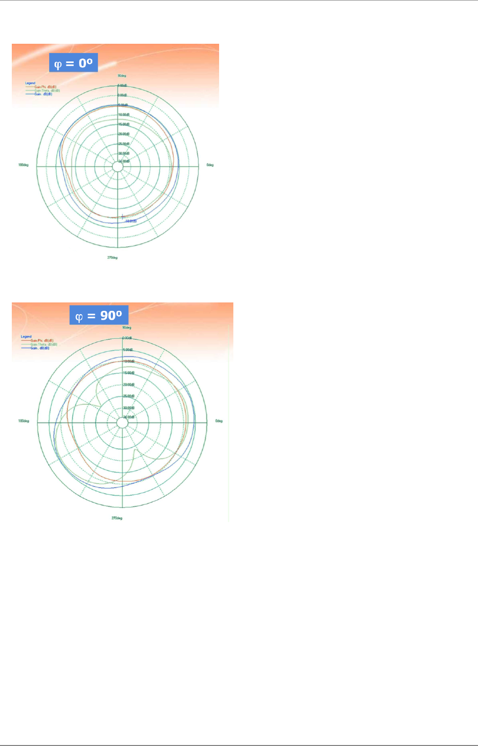
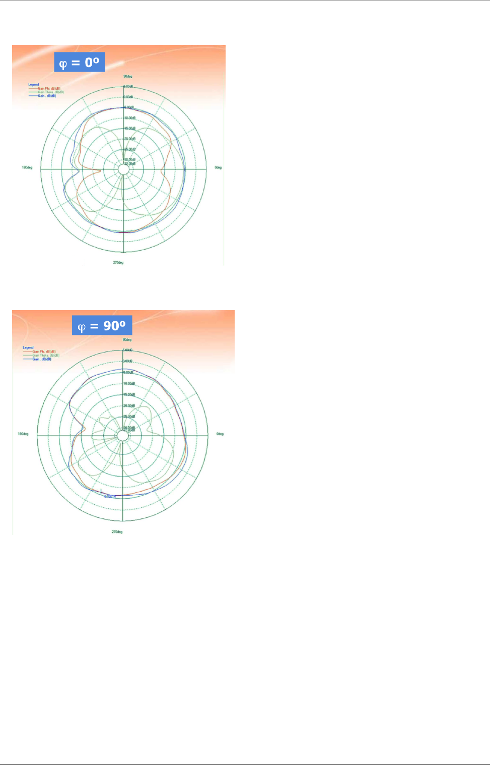
4.1 Surface mounted antenna (internal)
Part number cB-0941-02 (OWL253i / OWS451i)
Antenna FR05-S1-NO-1-004
Manufacturer Fractus
Gain 0 dBi @ 2.4GHz, 3 dBi @ 5GHz
avg. VSWR 3.1 @ 2.4GHz, 2.3 @ 5GHz
avg. Efficiency 22% @ 2.4GHz, 39% @ 5GHz
Antenna size (LxWxH) 7 x 3 x 2 mm
Comments The antenna gain is very dependent of the mounting of the module.
The unit cannot be mounted in a metal-shielded enclosure with this antenna.
4.1.1 Radiation patterns
connectBlue
Copyright © 2010 connectBlue AB Page 13 of 34
4.1.1.1 Radiation Pattern Cuts @2450 MHz – Free Space
connectBlue
Copyright © 2010 connectBlue AB Page 14 of 34
4.1.1.2 Radiation Pattern Cuts @5400 MHz – Free Space

connectBlue
Copyright © 2010 connectBlue AB Page 15 of 34
4.2 External antennas
The external antennas are connected to the module with the on board U.FL connectors. Some antennas are connected directly to
the U.FL connector and some are connected via a U.FL to SMA (cB-ACC-18 or cB-ACC-48) or U.FL to reversed polarity SMA
(cB-ACC-38) adapter cable.
The sections below lists the antennas that are included in the radio type approvals of the module. For each antenna the "Approvals" field
defines in what country/region the antenna is allowed to use. Definitions of the "Approvals" field are:
FCC - The antenna is included in the FCC test reports, and thus approved for use in countries that accept the FCC radio
approvals, primarily US.
IC - The antenna is included in the IC (Industrie Canada) test reports, and thus approved for use in countries that accept the IC
radio approvals, primarily Canada.
R&TTE - The antenna is included in the R&TTE test reports, and thus approved for use in countries that accept the R&TTE radio
approvals, primarily the European countries.
In general, antennas with Reverse Polarity SMA connector or U.FL connector are included in FCC, IC and R&TTE radio tests.
Antennas with SMA connector are not allowed to be used in Canada and USA due to FCC/IC regulations but are in general included in
R&TTE radio tests.
Antennas with a part number in the form "cB-ACC-XX" are available for orders via the connectBlue distribution network.
For information about other antennas please contact connectBlue
connectBlue
Copyright © 2010 connectBlue AB Page 16 of 34
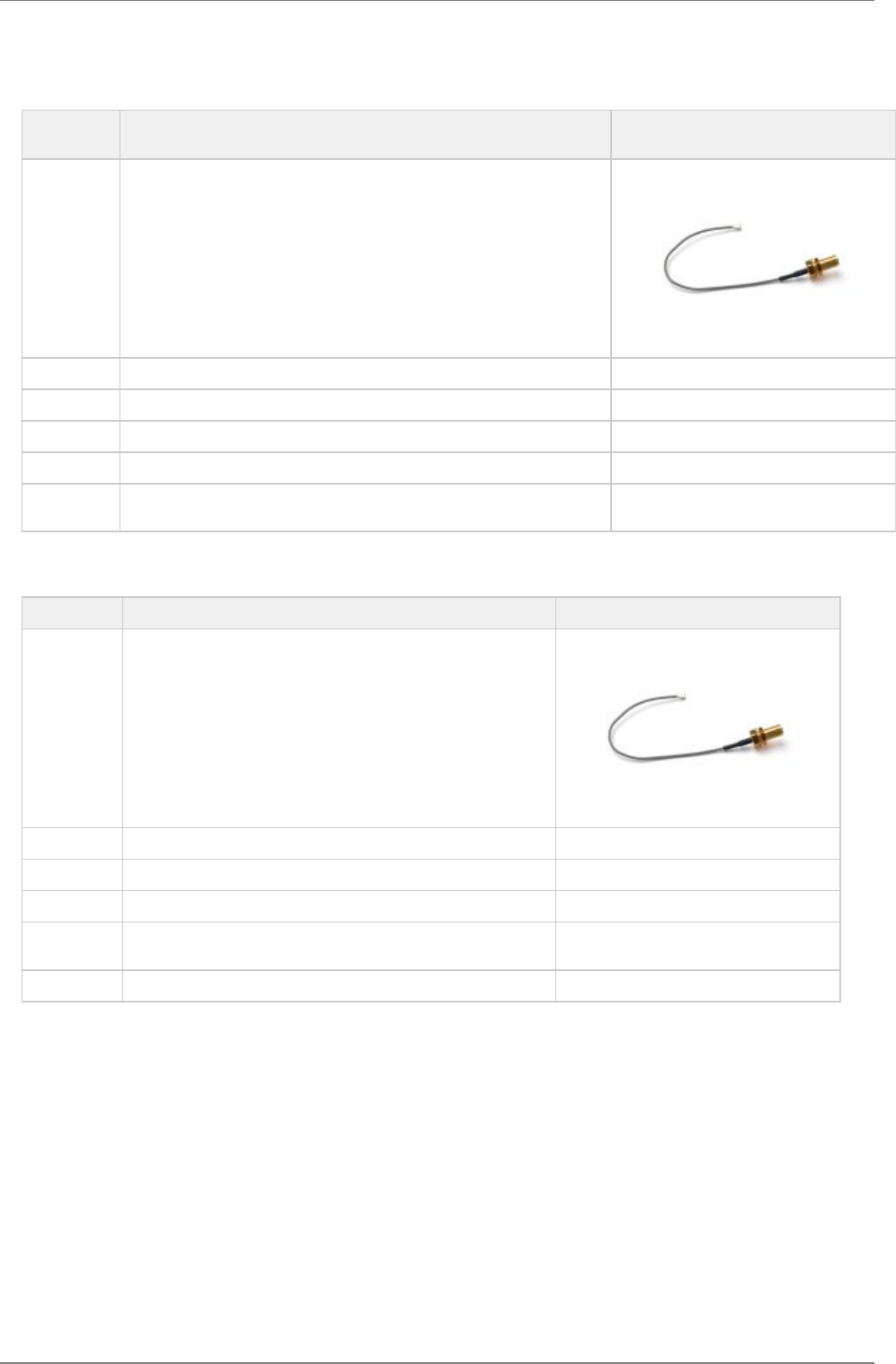
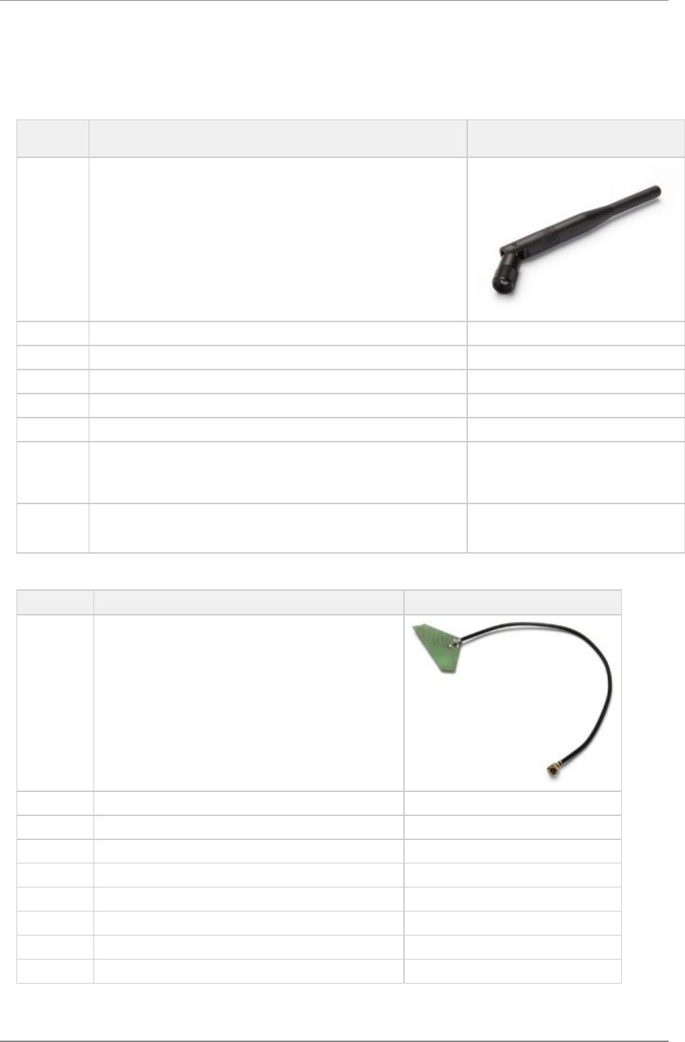
4.3 Antenna accessories
Part
Number cB-ACC-18 / cB-ACC-48
Name U.FL to SMA adapter cable
Connector U.FL and SMA jack (outer thread and pin receptacle)
Cable length 120 mm
Cable loss Less than 0.5 dB
Comment The SMA connector may be mounted in a panel.
Approval Approved for use in Europe but NOT approved for use in the US and
Canada.
Part Number cB-ACC-38
Name U.FL to Reverse Polarity SMA adapter cable
Connector U.FL and Reverse Polarity SMA jack (outer thread and pin)
Cable length 120 mm
Cable loss Less than 0.5 dB
Comment The Reverse Polarity SMA connector may be mounted in a panel.
Approval Approved for use in US, Canada and Europe.
connectBlue
Copyright © 2010 connectBlue AB Page 17 of 34
4.4 Antennas
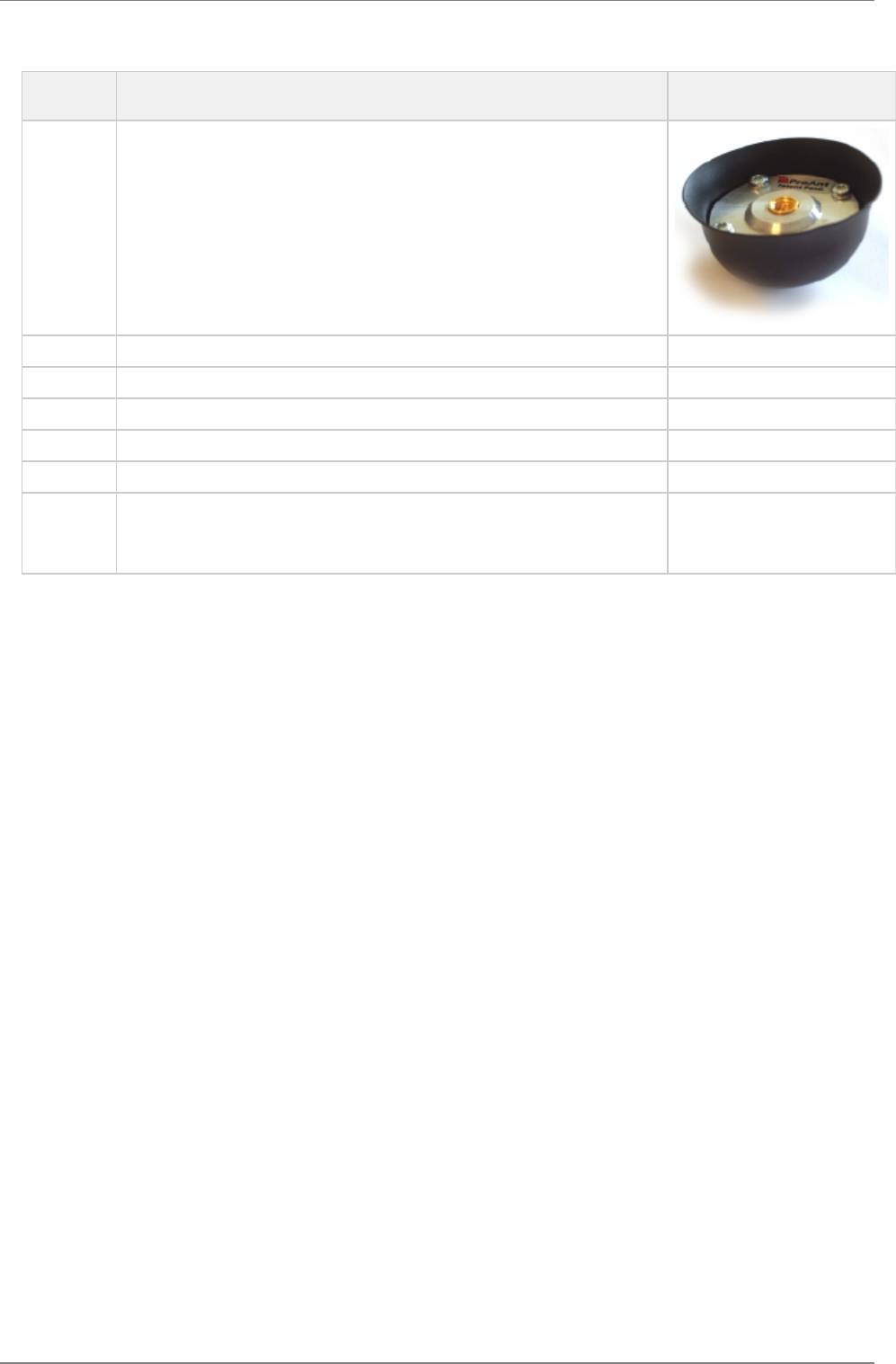
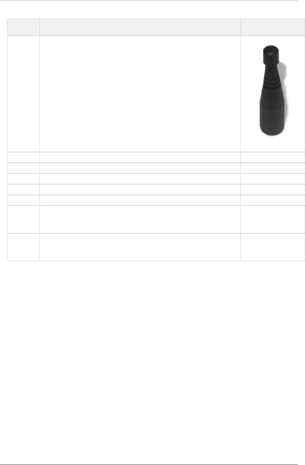
4.4.1 Recommended antennas
Part
Number cB-ACC-53
Name Ex-IT WLAN RP-SMA
(dual-band)
Manufacture ProAnt
Polarization Vertical
Gain / Imp. +3.0 dBi / 50ohm @ 2.4 GHz, +3.0 dBi / 50ohm @ 5 GHz
Size Ø 10 x 107 mm
Connector Reverse Polarity SMA plug (inner thread and pin receptacle)
Comment To be used together with the U.FL to Reverse Polarity SMA adapter cable
(cB-ACC-38).
An alternative SMA version antenna is available but not recommended
(cB-ACC-54 / Ex-IT WLAN SMA).
Approval The antenna is approved for use in US, Canada and Europe.
The alternative SMA version is approved for use in Europe but NOT
approved for use in the US and Canada.
Part Number cB-ACC-55
Name InSide WLAN
(dual band)
Manufacture ProAnt
Polarization Vertical
Gain / Imp. +3.0 dBi / 50ohm @ 2.4 GHz +3.0 dBi / 50ohm @ 5 GHz
Size 27 x 12 mm (triangular)
Cable length 100 mm
Connector U.FL
Comment To be connected to the U.FL connector on the PCB.
Approval The antenna is approved for use in US, Canada and Europe.
connectBlue
Copyright © 2010 connectBlue AB Page 18 of 34
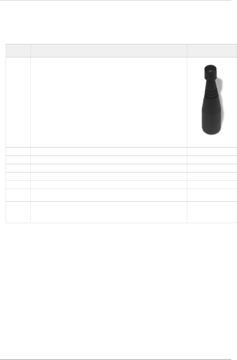
Part
Number cB-ACC-66
Name FlatWhip 2400
Manufacture ProAnt
Gain / Imp. +3.0 dBi / 50ohm
Size Ø 50.0 x 30.0 mm
Connector SMA plug (inner thread and pin)
Comment To be used together with the U.FL to SMA adapter cable.
Approval The antenna is approved for Europe but NOT approved for use in the US and
Canada.
Please contact connectBlue for information about US and Canada approved
versions of the antenna with Reverse Polarity SMA connector.
connectBlue
Copyright © 2010 connectBlue AB Page 19 of 34
4.4.2 Alternative antennas
The alternative antennas are available for backward compability but not recommended for new designs.
Part
Number cB-ACC-21
Name R380.500.127
Manufacture Pulse
Polarization Vertical
Gain / Imp. +2.0 dBi / 50ohm
Size Ø 14.3 x 61.4 mm
Connector SMA plug (inner thread and pin)
Comment To be mounted on the U.FL to SMA adapter cable (cB-ACC-18 or cB-ACC-48).
A Reverse Polarity SMA version is also available (R380.500.125).
Approval The SMA version is approved for use in Europe but NOT approved for use in the US and
Canada.
The alternative Reverse Polarity SMA version antenna is approved for use in the US,
Canada and Europe.
connectBlue
Copyright © 2010 connectBlue AB Page 20 of 34
Part
Number —
Name R380.500.139
Manufacture Pulse
Polarization Vertical
Gain / Imp. +2.0 dBi / 50 ohm
Size Ø 14.3 x 61.1 mm
Connector Reverse Polarity SMA plug (inner thread and pin receptacle)
Comment The difference compared to the R380.500.125 antenna is that the R380.500.139 antenna
has a seal ring.
To be mounted on the U.FL to Reverse Polarity SMA adapter cable (cB-ACC-38).
An SMA version antenna is also available (R380.500.124).
Approval The Reverse Polarity SMA version antenna is approved for use in the US, Canada and
Europe.
The alternative SMA version is approved for use in Europe but NOT approved for use in
the US and Canada.
connectBlue
Copyright © 2010 connectBlue AB Page 21 of 34
4.4.3 Customer specific antennas
Part Number —
Name InSide EPA WLAN
Manufacture ProAnt
Polarization Circular
Gain / Imp. +3.0 dBi / 50 ohm
Size 66 x 90 x 36 mm
Connector U.FL-R-SMT
Comment Frequency 5150 - 5350 MHz (5.0 - 6.0 GHz)
Approval approved for use in the US, Canada and Europe.
Part Number —
Name Inside EPA 2400
Manufacture ProAnt
Polarization Mixed horizontal and vertical
Gain / Imp. +3.0 dBi / 50 ohm
Size 66 x 90 x 36 mm
Connector U.FL-RSMT
Comment Frequency 2400 - 2485 MHz
Approval approved for use in the US, Canada and Europe.
Part Number —
Name SDM2-2400 / 1575
Manufacture Mobile Mark
Polarization Vertical
Gain / Imp. +2.0 dBi / 50 ohm
Size Ø 65.0 x 28.6 mm
Cable length 200 mm
Connector U.FL
Comment Frequency 2400 - 2500 MHz
Approval approved for use in the US, Canada and Europe.
connectBlue
Copyright © 2010 connectBlue AB Page 22 of 34
5 Mounting information
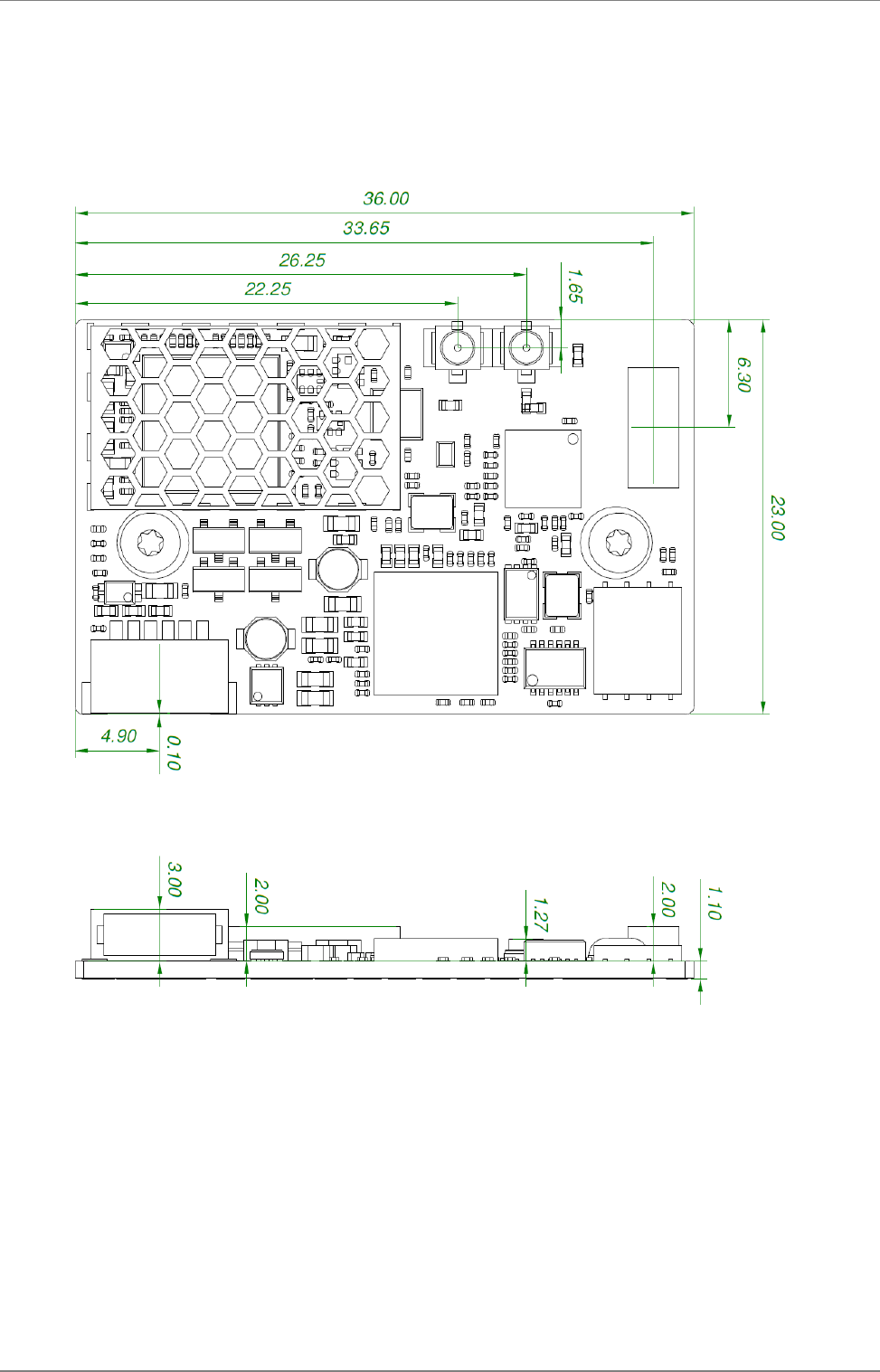
5.1 Module dimensions
connectBlue
Copyright © 2010 connectBlue AB Page 23 of 34
1.
2.
Tolerances:
Outline dimensions +/- 0.1mm
Drilled hole to outline: +/- 0.05mm
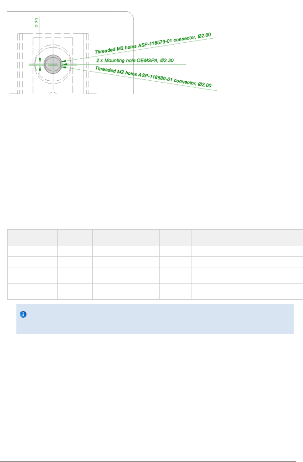
5.1.1 Mounting holes
There are 2 x 2.3mm mounting holes on cB-0942. The reasons for the 2.3mm holes are that the threaded M2 holes on the single and
double row connectors (see section 4.2.1) are not aligned. The outer tangents of the 2.3mm holes align the module if the single row
connectors are used and the inner if double row connectors are used (see Figure 11).
Choose the outer tangent (CC distance 27.24mm) if the module is aligned and mounted with some other technique based on M2 screws
(e.g. press-fit nuts), see Figure 12.
connectBlue
Copyright © 2010 connectBlue AB Page 24 of 34
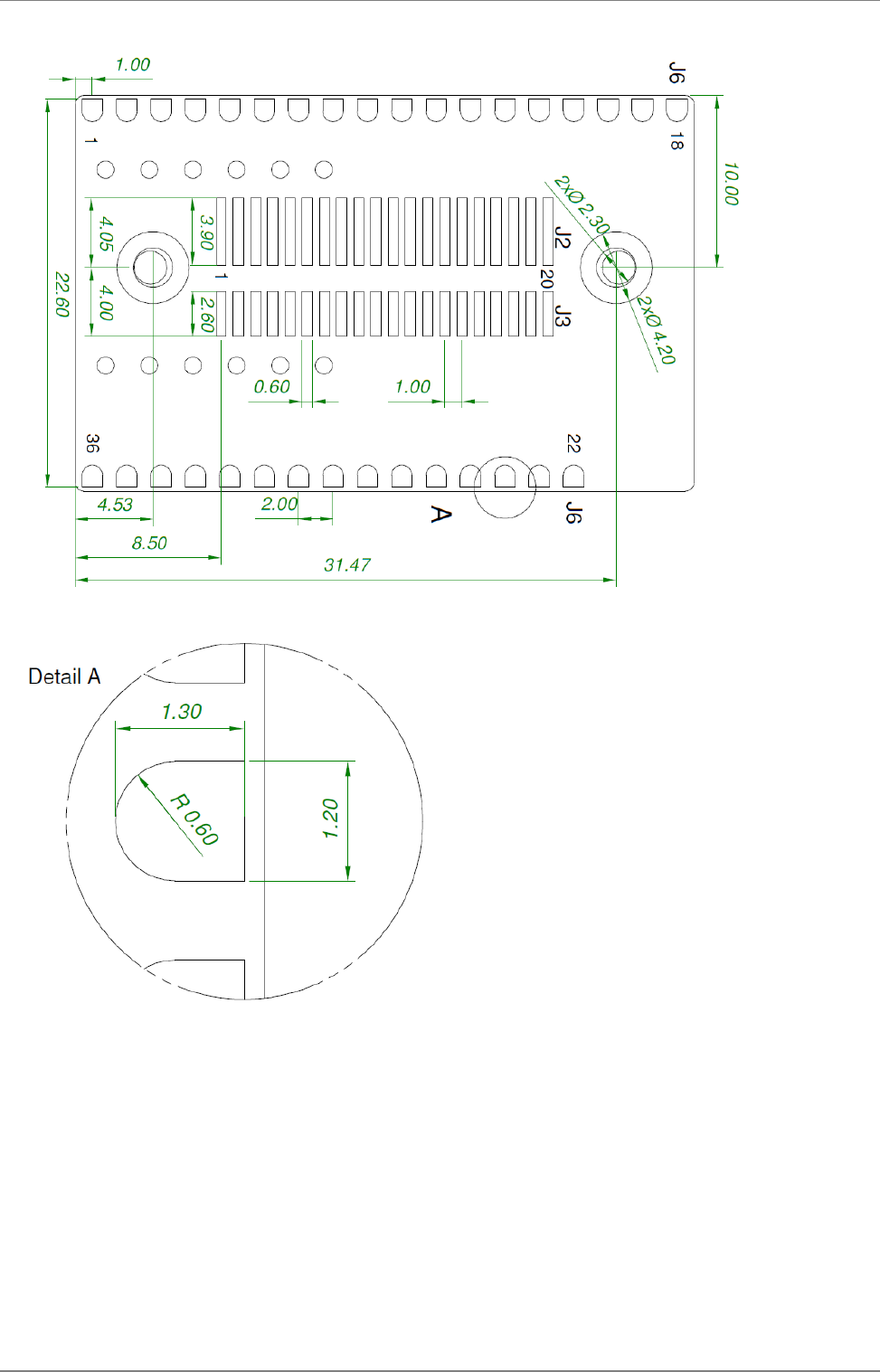
5.2 Using the J2/J3 board-to-board connectors
The board-to-board connector should be a 1 mm pitch one-piece part connector. The recommended manufacture is Samtec with many
connector options available; see section 4.2.1.1.
Chapter 2 contains more information about the connector and the electrical interface.
5.2.1 Suitable one-piece part connectors
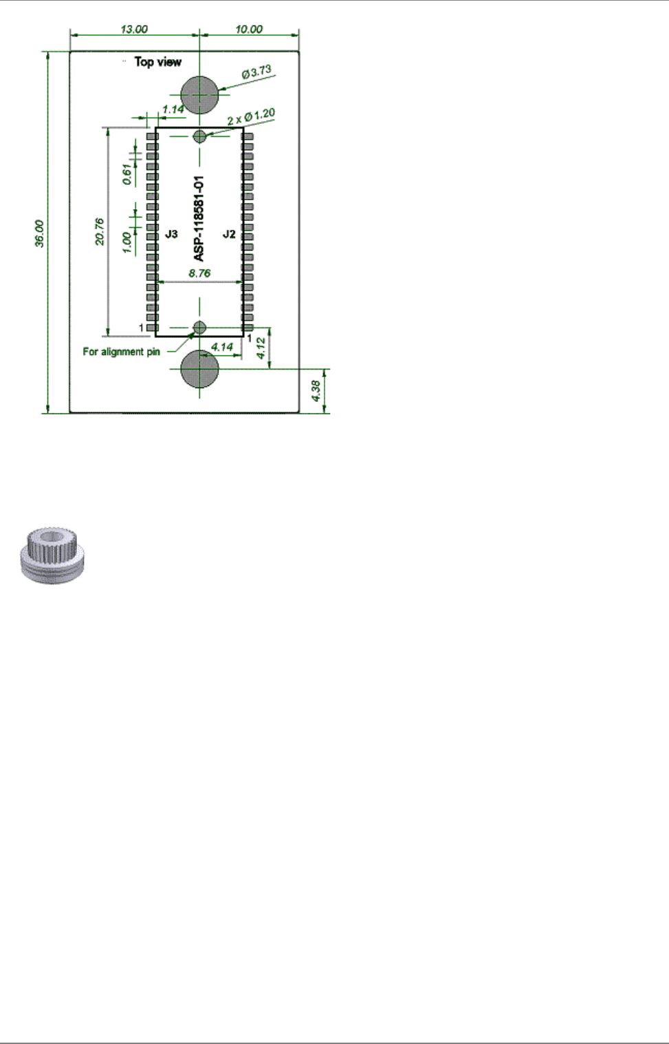
5.2.2 Double row ASP-118580-01 / ASP-118581-01 connectors
This connector is a double row connector and connects both J2 and J3. It connector has a height of 3.0 mm and this has to be
considered if components are to be mounted on the motherboard under the board. The connector is also available with a height of 6.0
mm and 10.0 mm (The FSI-120 serie from Samtec).
There are alignment pins on the bottom side of the connector.
The connector is available with M2 threaded inserts (ASP-118580-01) that fit the mounting holes on the board. You may screw the board
directly into these inserts. If you want to have a tighter and more secure mounting you may use longer screws and secure it using a nut
on the backside of the motherboard.
Another way to mount the module is to use press-fit nuts on the motherboard and skip the M2 threads on the connector
(ASP-118581-01), see section 4.3 for more information about press-fit nuts.
Samtec order
number Quote
number Equivalent part Package Remark
REF-120021-01 55392 FSI-120-03-G-D-AB Tube Align pin on bottom side only
REF-120021-02 55392 FSI-120-03-G-D-AB-K-TR Tape-n-Reel Align pin on bottom side only
REF-120018-01 55392 FSI-120-03-G-D-M-AB Tube With M2 threaded inserts and align pin on bottom
side only
REF-120018-02 55392 FSI-120-03-G-D-M-AB-K-TR Tape-n-Reel With M2 threaded inserts and align pin on bottom
side only
When ordering connectors from Samtec or an official Samtec distributor, please use the REF order number and refer to
the connectBlue global quote number for best price. For technical questions regarding the Samtec connectors please
contact connectBlue or Samtec at Scandinavia@samtec.com.
See figure below for more information about the connector and necessary measurements on the motherboard. The large mounting holes
on the motherboard are designed for press-fit nuts and could be smaller if press-fit nuts are not used.
connectBlue
Copyright © 2010 connectBlue AB Page 25 of 34
5.3 Using press-fit nuts for mounting
A press-fit nut is pressed into the PCB from the bottom side with a special press tool. M2 sized press-fit nuts are suitable for the modules
(see figure below) and are manufactured by PEM Fastening Systems, , part no KFS2-M2. Be careful with the distancewww.pemnet.com
between the nuts regarding alignment.
Spacer-pipes are recommended to use between the PCBs when press-fit nuts are used.
connectBlue
Copyright © 2010 connectBlue AB Page 26 of 34
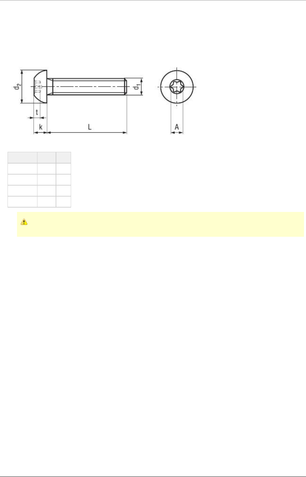
5.4 Recommended M2 screw
If a double-row connector with threaded inserts or press-fit nuts are used, then recommended for mounting of modules is a ISO 7380 M2
compatible screw. A suitable screw is the BN6404 from Bossard, , with TORX T6 head cap. See figure below.www.bossard.com
Parameter Value Unit
d2 3.5 mm
k max 1.3 mm
t max 0.8 mm
A 2.0 mm
If other type of screw is used please ensure that d2 is less than 3.8 mm otherwise components near the mounting holes
can be damaged.
5.5 Antenna issues
The unit cannot be mounted arbitrary, because of the radio communication. The unit with an internal surface mounted antenna cannot be
mounted in a metal enclosure. No metal casing or plastics using metal flakes should be used, avoid also metallic based paint or lacquer.
Keep a minimum clearance of 10 mm between the antenna and the casing. Keep 10 mm free space from metal around the antenna. If a
metal enclosure is required, one of the external antenna options has to be used. See section 3.2 for more information on the antenna
options available.
connectBlue
Copyright © 2010 connectBlue AB Page 27 of 34
6 WLAN information
In the tables below you can find information about WLAN properties.
Parameter Data
Radio Redpine Signals RS9110 + Airoha 8230
RF output power 802.11b (CCK): +20dBm (typ.)
802.11g (OFDM): +17dBm (typ.)
802.11a (OFDM): +10dBm (typ.)
Receiver sensitivity See table below
Receive input level (max) -10 dBm
Output frequency 2.412 - 2.462 GHz, channel 1 - 11
5 MHz channel separation
5.180 - 5.240 GHz, U-NII-1, channel 36, 40, 44, 48
20 MHz channel separation
Bluetooth co-existence CSR traditional 3-wire
6.1 Radio sensitivity OFDM
Data rate 802.11gn (channel 6, 2437MHz, dBm) 802.11an (channel 36, 5180MHz, dBm)
MCS7 -69 -68
MCS6 -70 -70
MCS5 -72 -72
MCS4 -76 -76
MCS3 -79 -79
MCS2 -82 -82
MCS1 -84 -83
MCS0 -87 -86
54 -73 -72
48 -75 -73
36 -78 -78
24 -83 -80
18 -85 -83
12 -87 -85
9 -88 -86
6 -89 -87

connectBlue
Copyright © 2010 connectBlue AB Page 28 of 34
6.2 Radio sensitivity DSSS
Data rate 802.11b (channel 6, 2437MHz, dBm)
11 -86
5.5 -89
2 -91
1 -94

connectBlue
Copyright © 2010 connectBlue AB Page 29 of 34
7 Regulatory information
Limitations
With current type approvals the module is allowed to operate only on the 2.4 GHz ISM band and on the 5 GHz U-NII band 1.
7.1 Declaration of conformity
We, connectBlue AB, of
Norra Vallgatan 64 3V
SE-211 22 Malmö, Sweden
declare under our sole responsibility that our product:
cB-0941-02 (OWL253i)
cB-0941-02 (OWL253x)
cB-0941-02 (OWS451i)
cB-0941-02 (OWS451x)
to which this declaration relates, conforms to the following product specifications:
R&TTE Directive 1999/5/EC
EN 300 328 V1.7.1 (2006-10)
EN 301 893 V1.5.1 (2008-12)
EN 301 489-1 V1.8.1 (2008-04)
EN 301 489-17 V2.1.1 (2009-05)
EN 61000-6-2 (2005)
Safety Compliance
IEC 60950-1: 2005 (2nd Edition) and/or EN 60950-1: 2006
Medical Electrical Equipment
IEC 60601-1-2 : 2007
2011-03-11 Malmö, Sweden
Mats Andersson
CTO of connectBlue AB
If cB-0941-02 is used within EU a notification may be necessary to be made to each of the national authorities responsible for radio
spectrum management of the intention to place radio equipment that uses frequency bands whose use is not harmonized throughout the
EU, on its national market.
More information at: http://europa.eu.int/comm/enterprise/rtte/gener.htm

connectBlue
Copyright © 2010 connectBlue AB Page 30 of 34
1.
2.
1.
2.
1.
2.
7.2 IC and FCC compliance
See for information about the different product variants.Product variants
7.2.1 IC Compliance
This device complies with Industry Canada licence-exempt RSS standard(s).
Operation is subject to the following two conditions:
this device may not cause interference, and
this device must accept any interference, including interference that may cause undesired operation of the device.
Under Industry Canada regulations, this radio transmitter may only operate using an antenna of a type and maximum (or lesser) gain
approved for the transmitter by Industry Canada. To reduce potential radio interference to other users, the antenna type and its gain
should be so chosen that the equivalent isotropically radiated power (e.i.r.p.) is not more than that necessary for successful
communication.
Within the band 5150 - 5250 MHz the operation of this device is restricted to indoor use to reduce the potential for harmful interference to
co-channel mobile sattelite systems.
This equipment complies with IC RSS-102 radiation exposure limits set forth for an uncontrolled environment. This equipment should be
installed and operated with minimum distance 20 cm between the radiator & your body.
7.2.2 Conformité aux normes d’IC
Cet appareil est conforme à la(aux) norme(s) RSS sans licence d’Industry Canada.
Son utilisation est soumise aux deux conditions suivantes :
Cet appareil ne doit pas causer d’interférences et
il doit accepter toutes interférences reçues, y compris celles susceptibles d’avoir des effets indésirables sur son fonctionnement.
Conformément aux réglementations d’Industry Canada, cet émetteur radio ne peut fonctionner qu’à l’aide d’une antenne dont le type et le
gain maximal (ou minimal) ont été approuvés pour cet émetteur par Industry Canada. Pour réduire le risque d’interférences avec d’autres
utilisateurs, il faut choisir le type d’antenne et son gain de telle sorte que la puissance isotrope rayonnée équivalente (p.i.r.e) ne soit pas
supérieure à celle requise pour obtenir une communication satisfaisante.
Dans la bande de fréquences 5150 - 5250 MHz, le fonctionnement de cet appareil est limité à une utilisation à l’intérieur pour réduire le
potentiel d’interférences brouillant les systèmes satellites mobiles d’un même canal.
Cet équipement respecte les limites d’exposition aux rayonnements IC RSS-102 définies pour un environnement non contrôlé. Il doit être
installé et utilisé en maintenant une distance minimum de 20 cm entre le radiateur et votre corps.
7.2.3 FCC statement
This device complies with Part 15 of the FCC Rules. Operation is subject to the following two conditions:
this device may not cause harmful interference, and
this device must accept any interference received, including interference that may cause undesired operation.
This equipment has been tested and found to comply with the limits for a Class B digital device, pursuant to Part 15 of
the FCC Rules. These limits are designed to provide reasonable protection against harmful interference in a residential
installation. This equipment generates, uses and can radiate radio frequency energy and, if not installed and used in
accordance with the instructions, may cause harmful interference to radio communications. However, there is no
guarantee that interference will not occur in a particular installation. If this equipment does cause harmful interference to
radio or television reception, which can be determined by turning the equipment off and on, the user is encouraged to
try to correct the interference by one or more of the following measures:
Reorient or relocate the receiving antenna
Increase the separation between the equipment and receiver
Connect the equipment into an outlet on a circuit different from that to which the receiver is connected
Consult the dealer or an experienced radio/TV technician for help.

connectBlue
Copyright © 2010 connectBlue AB Page 31 of 34
1.
2.
1.
2.
1.
2.
7.2.3.1 End product labelling requirements
For an end product using the product cB-0941-02 there MUST be a label containing, at least, the following information:
This device contains
FCC ID: PVH0941
IC: 5325A-0941
The label must be affixed on an exterior surface of the end product such that it will be visible upon inspection in compliance with the
modular approval guidelines developed by the FCC.
7.2.3.1.1 FCC End product labelling
In accordance with 47 CFR § 15.19 the end product shall bear the following statement in a conspicuous location on the device:
"This device complies with Part 15 of the FCC Rules. Operation is subject to the following two conditions:
this device may not cause harmful interference, and
this device must accept any interference received, including interference that may cause undesired operation."
When the device is so small or for such use that it is not practicable to place the statement
above on it, the information shall be placed in a prominent location in the instruction manual or pamphlet supplied to the user or,
alternatively, shall be placed on the container in which the device is marketed. However, the FCC ID label must be displayed on the
device.
In case, where the final product will be installed in locations where the end-consumer
is not able to see the FCC ID and/or this statement, the FCC ID and the statement shall also be included in the end-product manual.
7.2.3.1.2 IC End product labelling
User manuals for licence-exempt LPDs shall contain the following or equivalent statements in a conspicuous position:
Operation is subject to the following two conditions:
this device may not cause interference, and
this device must accept any interference, including interference that may cause undesired operation of the device.
7.2.3.1.3 Étiquetage du produit final conforme à IC
Les manuels d’utilisation d’appareils de faible puissance, sans licence, feront figurer à un endroit bien visible les mentions suivantes ou
équivalentes :
Son utilisation est soumise aux deux conditions suivantes :
Cet appareil ne doit pas causer d’interférences et
il doit accepter toutes interférences reçues, y compris celles susceptibles d’avoir des effets indésirables sur son fonctionnement.
connectBlue
Copyright © 2010 connectBlue AB Page 32 of 34
7.2.3.2 Antenna
Our module cB-0941-02 are for OEM integrations only. In the end-user product the module shall be professionally installed in such a
manner that only the authorized antennas can be used.
7.2.3.3 Caution
Any changes or modifications NOT explicitly APPROVED by connectBlue AB could cause the module to cease to
comply with FCC rules part 15, and thus void the user's authority to operate the equipment.
Within the 5150 to 5250 MHz band (5 GHz radio channels 34 to 48) the module type cB-0941-02 is restricted to indoor
operations to reduce any potential for harmful interference to co-channel MSS operation.
§15.407 statement; in case of absence of information to transmit or operational failure the module types cB-0941-02 will
automatically discontinue transmission.
7.2.3.4 Ad-hoc frequencies
Module cB-0941-02 when operating under the definition of a client in 47 CFR §15.202 is preconfigured to use the most restrictive
regulatory domain. For this reason the available operating frequency range is limited to channel 1 - 11 (2412 - 2462 MHz) for
IEEE802.11b/g. For IEEE802.11a the available operating frequency range is limited to channels 36 - 48 (5180 - 5240 MHz).
7.2.3.5 RF-exposure statement
This equipment complies with FCC radiation exposure limits set forth for an uncontrolled environment. This equipment should be installed
and operated with minimum distance 20 cm between the radiator & your body.
This equipment complies with IC RSS-102 radiation exposure limits set forth for an uncontrolled environment. This equipment should be
installed and operated with minimum distance 20 cm between the radiator & your body.
Cet équipement est conforme aux limites d'exposition de rayonnement d'IC RSS-102 déterminées pour un environnement non contrôlé.
Cet équipement devrait être installé et actionné avec la distance minimum 20 cm entre le radiateur et votre corps.
Any notification to the end user of installation or removal instructions about the integrated radio module is NOT allowed.
7.3 UL listing information
If a customer intends to UL list a product including the cB-0941 this information is useful.
The printed circuit board is produced according to the following specification:
UL recognized ZPMV2 min. 130 °C flame class V-0 or better.
7.4 Compliance with RoHS directive
The cB-0941-02 are produced according to the RoHS (Restriction of the use of certain Hazardous Substances in electrical and electronic
equipment) directive and complies with the directive.

connectBlue
Copyright © 2010 connectBlue AB Page 33 of 34
8 Guidelines for efficient and safe use
8.1 General
Read this information before using your cB-0941-02 module.
For any exceptions, due to national requirements or limitations, when using your WLAN module cB-0941-02, please contact connectBlue
AB.
Changes or modifications to the product not expressly approved by connectBlue AB will void the user's authority to
operate the equipment.
8.2 Product care
Do not expose your product to liquid or moisture.
Do not expose you product to extreme hot or cold temperature.
Do not expose your product to lit candles, cigarettes, cigars, open flames, etc.
Do not drop, throw or try to bend your product since rough treatment could damage your product.
Do not attempt to disassemble your product. Doing so will void warranty. The product does not contain consumer serviceable or
replaceable components. Service should only be performed by connectBlue AB.
Do not paint your product as the paint could prevent normal use.
If you will not be using your product for a while, store it in a place that is dry, free from
damp, dust and extreme heat and cold.
The clearance and creepage distances required by the end product must be withheld when the module is installed.
The cooling of the end product shall not negatively be influenced by the installation of the module when the module is installed.
8.3 Radio frequency exposure
The cB-0941-02 WLAN module contains a small radio transmitter and receiver.
During communication with other WLAN products the cB-0941-02 module transmits and receives radio frequency (RF) electromagnetic
fields (microwaves) in the frequency range 2412 - 2462 MHz and 5180 - 5240 MHz. The output power of the radio transmitter is very low.
When using the cB-0941-02, you will be exposed to some of the transmitted RF energy. This exposure is well below the prescribed limits
in all national and international RF safety standards and regulations.
8.4 Electronic equipment
Most modern electronic equipment, for example, in hospitals and cars, is shielded from RF energy. However, certain electronic
equipment is not. Therefore:
This equipment emits RF energy in the ISM (Industrial, Scientific, Medical) band. Please insure that all medical devices
used in proximity to this device meet appropriate susceptibility specifications for this type of RF energy.
8.5 Potentially explosive atmospheres
Turn off your electronic device before entering an area with potentially explosive atmosphere. It is rare, but your electronic device could
generate sparks. Sparks in such areas could cause an explosion or fire resulting in bodily injury or even death.
Areas with a potentially explosive atmosphere are often, but not always, clearly marked. They include fuelling areas, such as petrol
station, below deck on boats, fuel or chemical transfer or storage facilities, and areas where the air contains chemicals or particles, such
as grain, dust, or metal powders.
8.6 Safety compliance
In order to fulfill the safety standard EN 60950-1:2006 the WLAN module cB-0941-02 must be supplied by a Class-2 Limited Power
Source.
8.6.1 Power supply
Connect your power supply only to designated power-sources as marked on the product.
To reduce risk of electric shock, unplug the unit from any power source before attempting to clean it.

connectBlue
Copyright © 2010 connectBlue AB Page 34 of 34
9 Design examples
9.1 Basic design