Becker Avionics TG660 Aircraft radio User Manual Transceiver Family 620X
Becker Avionics, Inc. Aircraft radio Transceiver Family 620X
Contents
- 1. Manual_Family
- 2. Manual_PA3-2AB-AIR
- 3. Manual_TG660
- 4. User Manual
- 5. Datasheet
Manual_Family

Becker Avionics GmbH • Baden-Airpark B108 • 77836 Rheinmünster • Germany
+49 (0) 7229 / 305-0 • Fax +49 (0) 7229 / 305-217
http://www.becker-avionics.com • E-mail: info@becker-avionics.com
VHF-Transceiver
Family
AR620X-(X1X)
AR620X-(X2X)
RT6201-(X10)
RT6201-(X20)
RCU6201-(X12)
Software Versions:
from Software Version
SCI1050S305 Version 4.06
SCI1051S305 Version 2.06
Installation and Operation
Manual DV14307.03
Issue 04 March 2016
Article-No. 0638.404-071
General Description
Introduction
2 Transceiver Family 620X DV14307.03 Issue 04 March 2016
Preface
Dear Customer,
Thank you for purchasing Becker Avionics products.
We are pleased that you have chosen our product and we are confident that it will meet your
expectations.
For development of our product, the guidelines for highest quality and reliability have been borne in
mind, supplemented by selection of high quality material, responsible production and testing in
accordance to the ISO 9001 and DIN EN 9100 standards.
Our competent customer support department will respond on any technical question you may have.
Please do not hesitate to contact us at any time.
VHF-Transceiver Family
AR6201 (Single Block Transceiver)
RCU6201 (Remote Control Unit)
AR6203 (Single Block Transceiver)
RT6201 (Remote Transceiver)

General Description
Introduction
DV14307.03 Issue 04 March 2016 Transceiver Family 620X 3
List of Effective Pages and Changes
Only technical relevant modifications are described in this table.
Document: DV14307.03 / issue 04 Article Number 0638.404-071
Cover Page 03/2016
Introduction 03/2016
Chapter 1 – 4 03/2016
Issue Page No.: Section /
Chapter Description
04 1...116 all Changed: Editorial adjustments.
-- 1.7.9.1 Added: Description "FCC Approval"
--
--
--
--
--
--
--
--
--
--
--
--
--
--
--
--
© 2016 by Becker Avionics GmbH / all rights reserved

General Description
Introduction
4 Transceiver Family 620X DV14307.03 Issue 04 March 2016
Table of Contents
1. General Description ..................................................................................................................... 11
1.1. Introduction .................................................................................................................................. 12
1.2. Purpose of Equipment ................................................................................................................. 13
1.3. General Notes ............................................................................................................................. 13
1.4. Variants Overview ....................................................................................................................... 14
1.4.1. Software Status ................................................................................................................. 16
1.5. Short Description ......................................................................................................................... 16
1.5.1. AR6201 Single Block Transceiver..................................................................................... 16
1.5.2. RT6201 Remote Transceiver ............................................................................................ 17
1.5.3. RCU6201 Remote Control Unit ......................................................................................... 17
1.5.4. AR6203 Single Block Transceiver..................................................................................... 18
1.6. Features Overview ...................................................................................................................... 18
1.7. Technical Data ............................................................................................................................. 21
1.7.1. Receiver Data for AR620X and RT6201 ........................................................................... 22
1.7.2. Transmitter Data AR620X and RT6201 ............................................................................ 23
1.7.3. Dimensions & Weight ........................................................................................................ 24
1.7.4. Emergency Operation ....................................................................................................... 24
1.7.5. Environmental Qualification AR620X and RCU6201 ........................................................ 24
1.7.6. Environmental Qualification RT6201 ................................................................................ 26
1.7.7. Software ............................................................................................................................ 27
1.7.8. Complex Hardware ........................................................................................................... 27
1.7.9. Approvals .......................................................................................................................... 28
1.7.9.1. FCC Approval ........................................................................................................ 29
1.8. Order Code .................................................................................................................................. 30
1.8.1. 620X .................................................................................................................................. 30
1.8.2. Accessories ....................................................................................................................... 30
2. Installation .................................................................................................................................... 33
2.1. Limitations ................................................................................................................................... 33
2.2. Packaging, Transport, Storage .................................................................................................... 33
2.3. Device Assignment ...................................................................................................................... 34
2.3.1. Scope of Delivery .............................................................................................................. 34
2.3.2. Additional Required Equipment......................................................................................... 34
2.3.3. Type Plate ......................................................................................................................... 35
2.3.4. Software/Firmware Status – Functionality ........................................................................ 35
2.4. Mechanical Installation ................................................................................................................ 36
2.4.1. AR6201 and RCU6201 Installation (Back Panel Mounting) ............................................. 36
2.4.2. AR6203 Installation ........................................................................................................... 39
2.4.3. RT6201 Installation ........................................................................................................... 41
2.5. Electrical Interface ....................................................................................................................... 44
2.5.1. Connector and Pin Assignment (AR620X and RT6201) ................................................... 44
2.5.1.1. Inputs / Outputs ...................................................................................................... 47
2.5.2. Connector and Pin Assignment (RCU6201) ..................................................................... 51
2.6. Installation and Configuration ...................................................................................................... 52
2.7. Antenna Installation ..................................................................................................................... 53
2.8. Configuration Setup ..................................................................................................................... 53
2.8.1. Start Configuration Setup .................................................................................................. 54
2.8.2. Navigate between Pages .................................................................................................. 54
2.8.3. Store Setup Data ............................................................................................................... 54
2.8.4. Leave Configuration Setup ................................................................................................ 54
2.8.5. Adjust Volume Settings (VU Meter) .................................................................................. 54
2.8.6. Configuration Setup Pages - Description .......................................................................... 55
2.9. Factory Default Settings .............................................................................................................. 68
2.10. Wiring Diagrams and Settings ..................................................................................................... 70
2.10.1. Single Seat Glider ............................................................................................................. 70
2.10.1.1. Configuration Setup ............................................................................................... 70
2.10.1.2. Wiring Diagrams Single Seat Glider ...................................................................... 71
2.10.1.3. Wiring Diagrams Single Seat Glider 5-pol DIN Jack ............................................. 72
2.10.2. Twin Seat Motor Glider ..................................................................................................... 73
2.10.2.1. Configuration Setup ............................................................................................... 73

General Description
Introduction
DV14307.03 Issue 04 March 2016 Transceiver Family 620X 5
2.10.2.2. Wiring Diagram Twin Seat Motor Glider ................................................................ 74
2.10.3. General Aviation (GA) Aircraft .......................................................................................... 75
2.10.3.1. Configuration Setup (using Standard Microphones) ............................................. 75
2.10.3.2. Wiring Diagram General Aviation GA Using Standard Microphones .................... 76
2.10.4. Individual Dual Headset Configuration (two IC Circuit) .................................................... 77
2.10.4.1. Configuration Setup ............................................................................................... 77
2.10.4.2. Wiring Diagram Individual Dual Headset Configuration - two IC Circuit ............... 78
2.10.5. Twin Seat with AR620X Tandem Configuration ............................................................... 79
2.10.5.1. Configuration Setup ............................................................................................... 79
2.10.5.2. Wiring Diagram Twin Seat with AR620X Tandem Configuration .......................... 80
2.10.6. Aircraft with four Seats (no TANDEM) .............................................................................. 81
2.10.6.1. Configuration Setup ............................................................................................... 81
2.10.6.2. Wiring Diagram Aircraft with four Seats - no TANDEM ......................................... 82
2.10.7. Installation with RT6201 and RCU6201 ............................................................................ 83
2.10.7.1. Wiring Diagram with RT6201 and RCU6201......................................................... 83
2.10.8. Aircraft with Intercom System ........................................................................................... 84
2.10.8.1. Configuration Setup ............................................................................................... 84
2.10.8.2. Wiring Diagram Aircraft with Intercom System unbalanced .................................. 85
2.10.8.3. Wiring Diagram Aircraft with Intercom System Balanced ...................................... 86
2.10.9. Twin Seat with RT6201 Tandem Configuration ................................................................ 87
2.10.9.1. Configuration Setup ............................................................................................... 87
2.10.9.2. Wiring Diagram Twin Seat with RT6201 Tandem Configuration ........................... 88
2.11. Predesigned Cable Harness ....................................................................................................... 89
2.11.1. 1K065 for General Aviation ............................................................................................... 89
2.11.2. 1K062 (Open Cable Ends) ................................................................................................ 89
2.12. Retrofitting AR4201 with AR6201 ............................................................................................... 89
2.12.1. Pin Compatibility AR4201 - AR6201 ................................................................................. 90
2.12.2. Dynamic Microphone Input ............................................................................................... 91
2.12.3. Temperature Sensor ......................................................................................................... 91
2.12.4. RS232 Interface ................................................................................................................ 91
2.12.5. AFCU/AGC/AFWB ............................................................................................................ 92
2.12.6. CPIN (if Installed) .............................................................................................................. 92
2.12.7. +13.75 V Switched (AR4201) - PWR_EVAL (AR6201) .................................................... 92
2.13. Post Installation Tests ................................................................................................................. 92
2.13.1. Mechanical Installation and Wiring Check ........................................................................ 92
2.13.2. Power Supply .................................................................................................................... 92
2.13.3. Receiver / Transmitter Operation ...................................................................................... 92
2.13.4. Antenna Check ................................................................................................................. 92
2.13.5. Interference Check ............................................................................................................ 92
2.13.6. Flight Test Check .............................................................................................................. 94
2.14. Trouble Shooting ......................................................................................................................... 95
2.15. Continued Airworthiness ............................................................................................................. 96
3. Operating Instructions ................................................................................................................ 97
3.1. Device Description ...................................................................................................................... 97
3.1.1. Device Assignment ........................................................................................................... 97
3.1.2. Type Plate ......................................................................................................................... 97
3.2. Controls and Indicators ............................................................................................................... 99
3.3. Start-Up ..................................................................................................................................... 100
3.4. Receive and Transmit Mode ..................................................................................................... 100
3.4.1. Receive Mode ................................................................................................................. 100
3.4.2. Transmit Mode ................................................................................................................ 100
3.5. Frequency Selection Modes...................................................................................................... 101
3.5.1. Standard Mode ............................................................................................................... 101
3.5.2. Direct Tune Mode ........................................................................................................... 102
3.5.3. Channel Mode ................................................................................................................. 104
3.5.3.1. Select Channels .................................................................................................. 104
3.5.4. Frequency Storage Functions ......................................................................................... 105
3.5.4.1. Store .................................................................................................................... 105
3.5.5. Automatic Storage Function ........................................................................................... 106
3.5.5.1. Delete data: ......................................................................................................... 106
3.5.6. Scan Mode ...................................................................................................................... 107

General Description
Introduction
6 Transceiver Family 620X DV14307.03 Issue 04 March 2016
3.6. SQUELCH ................................................................................................................................. 108
3.7. RX Field Strength Indication ...................................................................................................... 108
3.8. Channel Spacing Mode ............................................................................................................. 108
3.9. Auxiliary Audio Input .................................................................................................................. 109
3.10. Intercom Operation .................................................................................................................... 109
3.11. VOX & Speaker Operation ........................................................................................................ 110
3.12. Menus ........................................................................................................................................ 110
3.12.1. Intercom Menu ................................................................................................................ 110
3.12.2. User Menu ....................................................................................................................... 112
3.13. Warning and Failure Indications ................................................................................................ 113
4. Index ............................................................................................................................................ 116

General Description
Introduction
DV14307.03 Issue 04 March 2016 Transceiver Family 620X 7
List of Abbreviations
List of Abbreviations
AC
Alternating Current
AF
Audio Frequency
AR
Airborne Radio
ATT
Attenuation
AUX
Auxiliary
AWG
American Wire Gauge
BNC
Bayonet Neill Concelman
CBIT
Continuous Built-In Test
CFG
Configuration
CH
Channel
CM
Chassis Core Module
COM
Communication
DC
Direct Current
EASA
European Aviation Safety Agency
EMI
Electro Magnetic Interference
ETSO
European Transmission System Operators
EUROCAE
European Organisation for Civil Aviation Equipment
FAA
Federal Aviation Administration
GND
Ground (Aircraft Ground)
GPS
Global Positioning System
HIRF
High Intensity Radiated Fields
HMI
Human Machinery Interface
I&O
Installation & Operation
IC
Intercom
LCD
Liquid Crystal Display
M&R
Maintenance & Repair
MFD
Multi-Function Display
N/A
Not Applicable
NAV
Navigation
PBIT
Power-On Built In Test
PTT
Push To Talk
PWR
Power
RCU
Remote Control Unit
RSSI
Received Signal Strength Indication
RT
Remote Transceiver
RX
Receive
SPKR
Speaker (Loudspeaker)
SQL
Squelch
SRC
Source
SW
Software
TSO
Technical Standard Order

General Description
Introduction
8 Transceiver Family 620X DV14307.03 Issue 04 March 2016
List of Abbreviations
TX
Transmit
VDC
Voltage Direct Current
VHF
Very High Frequency
VOX
Voice Operated IC Threshold
VSWR
Voltage Standing Wave Ratio
VU
Volume Unit
Units
Units
V
Volt
mV
Millivolt
A
Ampere
mA
Milliampere
W
Watt
mW
Milliwatt
kHz
Kilohertz
MHz
Megahertz
s
Second
dBm
Power ratio in Decibel
dB
Decibel
Ohm (Ω)
Resistor
kg
Kilogram
°C
Degree Celsius
mm
Millimetre
cm
Centimetre
General Safety Definitions
Indicates a hazardous situation which, if not avoided, will result in death or
serious injury.
Indicates a hazardous situation which, if not avoided, could result in death or
serious injury.
Indicates a hazardous situation which, if not avoided, could result in minor or
moderate injury.
Is used to address practices not related to physical injury.
Safety instructions (or equivalent) signs indicate specific safety-related
instructions or procedures.
General Description
Introduction
DV14307.03 Issue 04 March 2016 Transceiver Family 620X 9
Disposal
The packaging material is inflammable, if it is disposed of improperly by
burning, lethal fumes may develop.
This product contains materials that fall under the special disposal regulation, which corresponds to
the EC directive for dangerous disposal material. We recommend disposing of the respective materials
in accordance with the respectively valid environmental laws. The following table states the materials
suitable for recycling and the materials which have to be disposed of separately.
Material
Suitable for recycling
Disposal
Metal
yes
no
Plastics
yes
no
Circuit boards
no
yes
Dispose of the circuit boards:
• Disposal via a technical waste dump which is allowed to take on e.g. electrolytic
aluminium capacitors. Do under no circumstances dump the circuit boards with normal
waste dump.
Warranty Conditions
User Conversions and Changes are not permitted
Any change made by the user excludes any liability on our part (excluding updates for the navigation
data base).
• The device must not be opened.
• Do not make any modifications to the device, except for those described in the manual.
• Make connections to the inputs, outputs and interfaces only in the manner described in
the manual.
• Fix the devices according to the mounting instructions.
We cannot provide any guarantee for other mounting methods.
Conditions of Utilization
General introductory notes
With this device you bought a product which was manufactured and tested before delivery with the
utmost care.
Please take your time to read the following notes which you ought to follow closely during installation
and operation.
Unless, all claims under the warranty will become void and a reduced service life or even damages
must be expected.
The user is responsible for protective covers and/or additional safety
measures in order to prevent damages to persons and electric
accidents.
Additional Conditions of Utilization
Please refer to "Limitations", page 33.
Non Warranty Clause
We checked the contents of this publication for compliance with the associated hard and software. We
can, however, not exclude discrepancies and do therefore not accept any liability for the exact
compliance. The information in this publication is regularly checked, necessary corrections will be part
of the subsequent publications.

General Description
Introduction
10 Transceiver Family 620X DV14307.03 Issue 04 March 2016
Blank Page

General Description
Introduction
DV14307.03 Issue 04 March 2016 Transceiver Family 620X 11
1. General Description
In this chapter you can read about:
1.1. Introduction.................................................................................................................................. 12
1.2. Purpose of Equipment ................................................................................................................. 13
1.3. General Notes ............................................................................................................................. 13
1.4. Variants Overview ....................................................................................................................... 14
1.4.1. Software Status ................................................................................................................. 16
1.5. Short Description ......................................................................................................................... 16
1.5.1. AR6201 Single Block Transceiver .................................................................................... 16
1.5.2. RT6201 Remote Transceiver ............................................................................................ 17
1.5.3. RCU6201 Remote Control Unit ........................................................................................ 17
1.5.4. AR6203 Single Block Transceiver .................................................................................... 18
1.6. Features Overview ...................................................................................................................... 18
1.7. Technical Data ............................................................................................................................ 21
1.7.1. Receiver Data for AR620X and RT6201........................................................................... 22
1.7.2. Transmitter Data AR620X and RT6201 ............................................................................ 23
1.7.3. Dimensions & Weight........................................................................................................ 24
1.7.4. Emergency Operation ....................................................................................................... 24
1.7.5. Environmental Qualification AR620X and RCU6201 ........................................................ 24
1.7.6. Environmental Qualification RT6201 ................................................................................ 26
1.7.7. Software ............................................................................................................................ 27
1.7.8. Complex Hardware ........................................................................................................... 27
1.7.9. Approvals .......................................................................................................................... 28
1.7.9.1. FCC Approval ........................................................................................................ 29
1.8. Order Code.................................................................................................................................. 30
1.8.1. 620X .................................................................................................................................. 30
1.8.2. Accessories ....................................................................................................................... 30
This manual describes the installation and operation of the RCU-, RT-, AR6201 and AR6203
VHF Transceiver Family equipment. The ID label on your device shows the part number for
identification purposes.
Before starting operation of the unit(s) please read this manual carefully, with particular attention to the
description referring to your device(s). This manual also contains several optional elements of the
system (second controller for example), that may not be contained in your delivery package and in that
case are not applicable.

General Description
Introduction
12 Transceiver Family 620X DV14307.03 Issue 04 March 2016
1.1. Introduction
AR-, RT-, RCU620X VHF Transceivers are a modern family of communication equipment that have
comprehensive capabilities and significantly extend the typical aeronautical transceivers.
Despite its small size and weight the devices include inter alia:
• Sensitive receiver which meets the most recent requirements of ED-23C, including the
ability to work in the offset-carrier (climax) operation in 25 kHz and 8.33 kHz channel
spacing (class H2).
• Receiver includes SCAN (dual watch) mode. This allows simultaneous monitoring of two
different VHF frequency channels without interrupting communication on the active
frequency.
• High efficiency transmitter, which delivers more than 10 W modulated, or un-modulated,
output power at 28 V supply voltage, or 6 W at 12 V.
Lower power consumption allows longer operation from battery.
• Extended built-in intercom which can work as:
o 4-way intercom with isolation mode – passengers could continue conversation or
listening to music from MP3 player at the same time as pilots talk via intercom or
communicate with the tower.
o 2-way intercom for tandem operation – pilot and co-pilot work with separate
controllers and can control their individual audio parameters, like volume or VOX.
This mode is preferred especially for training due to full synchronization of LCD
contents.
• Non-volatile memory for storing:
o 99 channels can be labelled manually for storage of VHF frequencies.
o 9 recently selected VHF frequencies are automatically stored.
For further descriptions we are using following terms for VHF transceivers, VHF remote transceiver
and remote control unit, instead writing their complete model number.
620X in general for the device family.
AR620X for: AR6201, AR6203 (Single Block Transceiver).
RT for: RT6201 (Remote Transceiver).
RCU for: RCU6201 (Remote Control Unit).

General Description
Purpose of Equipment
DV14307.03 Issue 04 March 2016 Transceiver Family 620X 13
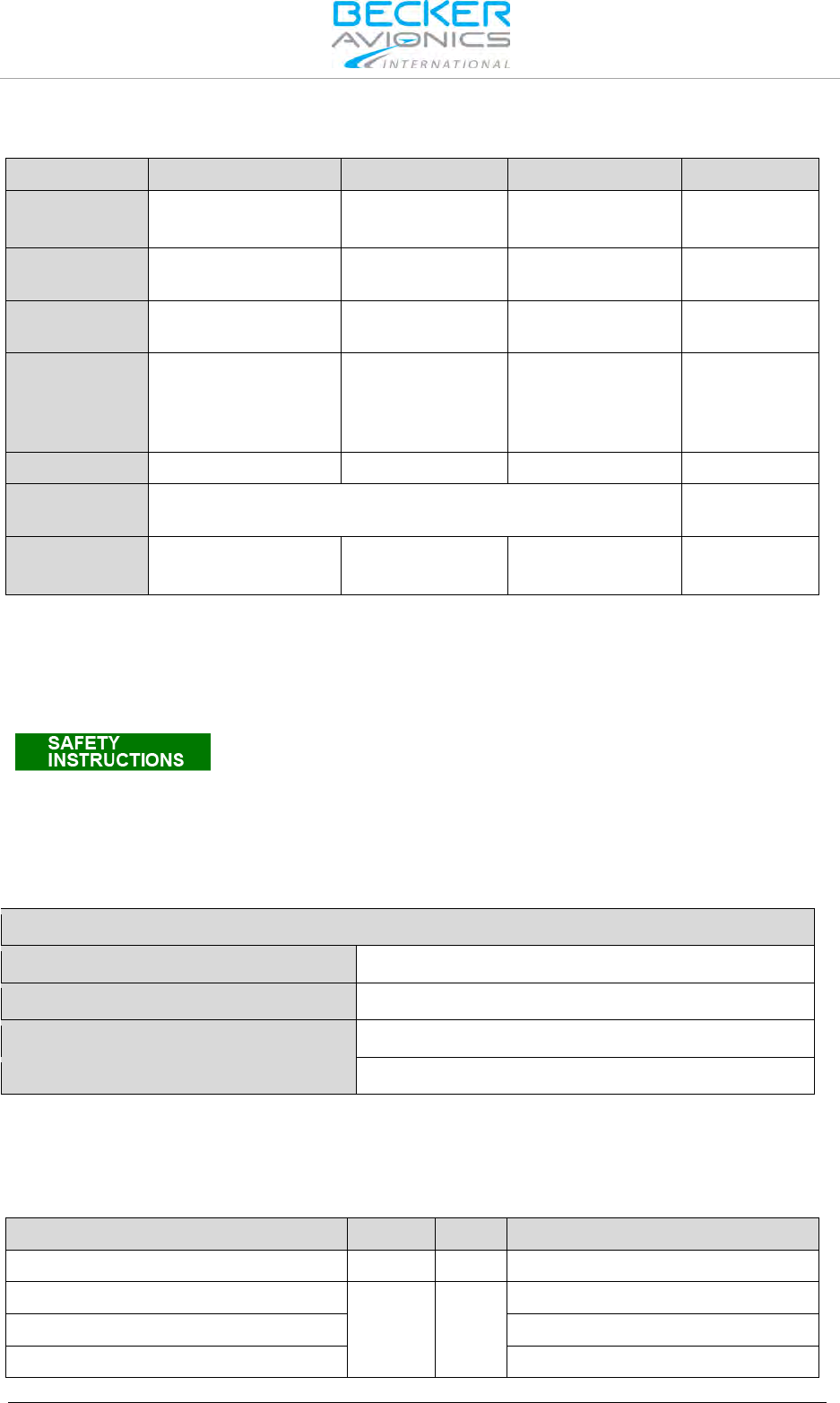
The manuals “Maintenance and Repair” (M&R), “Installation and Operation (I&O) and "Operation
Instructions" (OI) contain the following sections:
Section
DV 14307.04
M&R
DV 14307.03
I&O
OI
General X X N/A
Installation X X N/A
Operation X X X
Theory of Operation X N/A N/A
Maintenance and Repair X N/A N/A
Illustrated Parts List X N/A N/A
Modification and Changes X N/A N/A
Circuit Diagrams X N/A N/A
Certifications X N/A N/A
Attachments X N/A N/A
1.2. Purpose of Equipment
The 620X transceiver family enable voice communication between aircraft or between aircraft and
ground using the very high frequency band between 118.000...136.9916 MHz respectively
136.9750 MHz with a selectable channel spacing of 25 kHz respectively 8.33 kHz. The wide scope of
accessories also allows usage of the 620X VHF transceivers in ground-based applications.
The 620X Family is dedicated to applications where low power consumption is required. They are
capable to operate from standard 14 VDC and 28 VDC installations and from 12 VDC or 24 VDC
batteries.
Ultra low power consumption with extremely wide DC supply voltage range as well as compact and
lightweight design allows application for gliders and leisure aircraft up to 2000 kg and balloons.
Built-in 4-seat configurable intercom, transmitter output power up to 10 W and option for connection of
two controllers in tandem configurations extends the flexibility of the 620X Family.
The 620X transceivers also provide additional options such as:
• Intercom functionality for voice communication between aircraft crew and passengers
• Squelch functionality that automatically mutes receiver audio signal until clear signal is
received to avoid unwanted audio noise
• Scan functionality for simultaneous monitoring of two VHF channels (receive mode)
• AUX audio input for connection of additional audio devices like navigation receiver,
warning-tone generator, or MP3 music player.
• VHF channel database for easy access to predefined frequency channels
• Tandem functionality for synchronized operation of two controllers
1.3. General Notes
The word "frequency" also used in the sense of "channel name", as defined in EUROCAE,
document ED-23B chapter 1.3.2.
In this document the word "memory channel" or "channel" means a memory place identified by a
channel number, where a frequency may be stored for later use.
General Description
Variants Overview
14 Transceiver Family 620X DV14307.03 Issue 04 March 2016
1.4. Variants Overview
Within the part number, the meaning of "- (XXX)" is:
A
R
6
20
X
-
(X
X
X)
Identifier
2 - Blue White Backlight
Family Number
0 – Classic Design *1)
1 – New Design; 10 W *2)
2 – New Design; 6 W
*3)
1 – Square unit 2¼ inch
0 – Standard
3 – 160 mm
1 – 25 kHz only
Note:
*1) TX = 6 W; 2-seat IC
*2) TX = 10 W; 4 seat IC; Tandem capability; lower mounting depth.
*3) TX = 6 W; 4 seat IC; Tandem capability; lower mounting depth.
R
CU
6
20
X
-
(X
X
X)
Identifier
2 - Blue White Backlight
Family Number
0 – Classic Design
1 – New Design *4)
1 – Square unit 2¼ inch
0 – Standard
1 – 25 kHz only
*4) lower mounting depth.
General Description
Variants Overview
DV14307.03 Issue 04 March 2016 Transceiver Family 620X 15
R
T
6
20
X
-
(X
X
X)
Identifier
0 - Standard
Family Number
0 – Classic Design *5)
1 – New Design; 10 W *6)
2 – New Design; 6 W *7)
1 – Square unit 2¼ inch
0 – Standard
1 – 25 kHz only
Note:
*5) TX = 6 W; 2-seat IC
*6) TX = 10 W; 4 seat IC; Tandem capability; lower mounting depth.
*7) TX = 6 W; 4 seat IC; Tandem capability; lower mounting depth.
(0XX) indicates: 8.33/25 kHz channel spacing capability
(1XX) indicates: only 25 kHz channel spacing capability
(X1X) indicates: transmit power ≥ 6 W @ 14 V and 10 W @ 28 V
(X2X) indicates: transmit power ≥ 6 W @ 14 V and 6 W @ 28 V
(XX2) indicates: white illumination colour on a black panel
AR6201 Single Block Transceiver
Part Number
Article No
8.33 kHz Mode
25 kHz Mode
Transmit PWR
AR6201-(012) 0631.418-910 yes yes
≥ 6 W @ 14 V /
10 W @ 28 V
AR6201-(022) 0636.339-910 yes yes
≥ 6 W @ 14 V /
6 W @ 28 V
AR6201-(112) 0631.434-910 no yes
≥ 6 W @ 14 V /
10 W @ 28 V
AR6201-(122) 0636.355-910 no yes
≥ 6 W @ 14 V /
6 W @ 28 V
RT6201 Remote Transceiver
Part Number
Article No
8.33 kHz Mode
25 kHz Mode
Transmit PWR
RT6201-(010) 0631.442-910 yes yes
≥ 6 W @ 14 V /
10 W @ 28 V
RT6201-(020) 0636.312-910 yes yes
≥ 6 W @ 14 V /
6 W @ 28 V
RT6201–(110) 0638.609-910 no yes
≥ 6 W @ 14 V /
10 W @ 28 V
RT6201-(120) 0638.617-910 no yes
≥ 6 W @ 14 V /
6 W @ 28 V

General Description
Short Description
16 Transceiver Family 620X DV14307.03 Issue 04 March 2016
RCU6201 Remote Control Unit
Part Number Article No 8.33 kHz Mode 25 kHz Mode Transmit PWR
RCU6201-(012)
0631.469-910
yes
yes
N/A
RCU6201-(112) 0631.485-910 no yes N/A
AR6203 Single Block Transceiver
Part Number Article No 8.33 kHz Mode 25 kHz Mode Transmit PWR
AR6203-(012) 0630.993-910 yes yes
≥ 6 W @ 14 V /
10 W @ 28 V
AR6203-(022) 0636.371-910 yes yes
≥ 6 W @ 14 V /
6 W @ 28 V
AR6203-(112) 0631.566-910 no yes ≥ 6 W @ 14 V /
10 W @ 28 V
AR6203-(122) 0636.398-910 no yes
≥ 6 W @ 14 V /
6 W @ 28 V
1.4.1. Software Status
Description see "Software/Firmware Status – Functionality", page 35.
1.5. Short Description
For a "Side by Side" seat configuration, the following combinations apply:
• AR6201 or AR6203 Single Block Transceiver.
• RT6201 Remote Transceiver with Remote Control Unit (RCU6201).
For a "Tandem" seat configuration, the following combinations apply:
• AR6201 or AR6203 Single Block Transceiver with additional Remote Control Unit (RCU6201).
• RT6201 Remote Transceiver with Remote Control Unit (RCU6201) and additional second
Remote Control Unit (RCU6201).
In tandem configuration two controllers and one transceiver are connected. Tandem configuration is
useful for training purposes where pilot and student have their own controller with full-synchronized
views or as separate controllers for pilot and co-pilot.
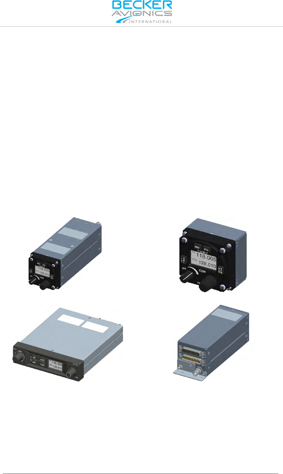
1.5.1. AR6201 Single Block Transceiver
The AR6201 is a compact and lightweight unit designed for operation in a cockpit environment for both
general aviation aircraft and helicopters. All controls and indicators are located on the front panel.
The equipment connectors and the antenna socket are located at the rear of the unit.
Installation via four screws (rear panel installation). The dimensions correspond to the standard
instrument diameter of 58 mm (2¼ inch).
Figure 1-1: AR6201 Single Block Transceiver
General Description
Short Description
DV14307.03 Issue 04 March 2016 Transceiver Family 620X 17
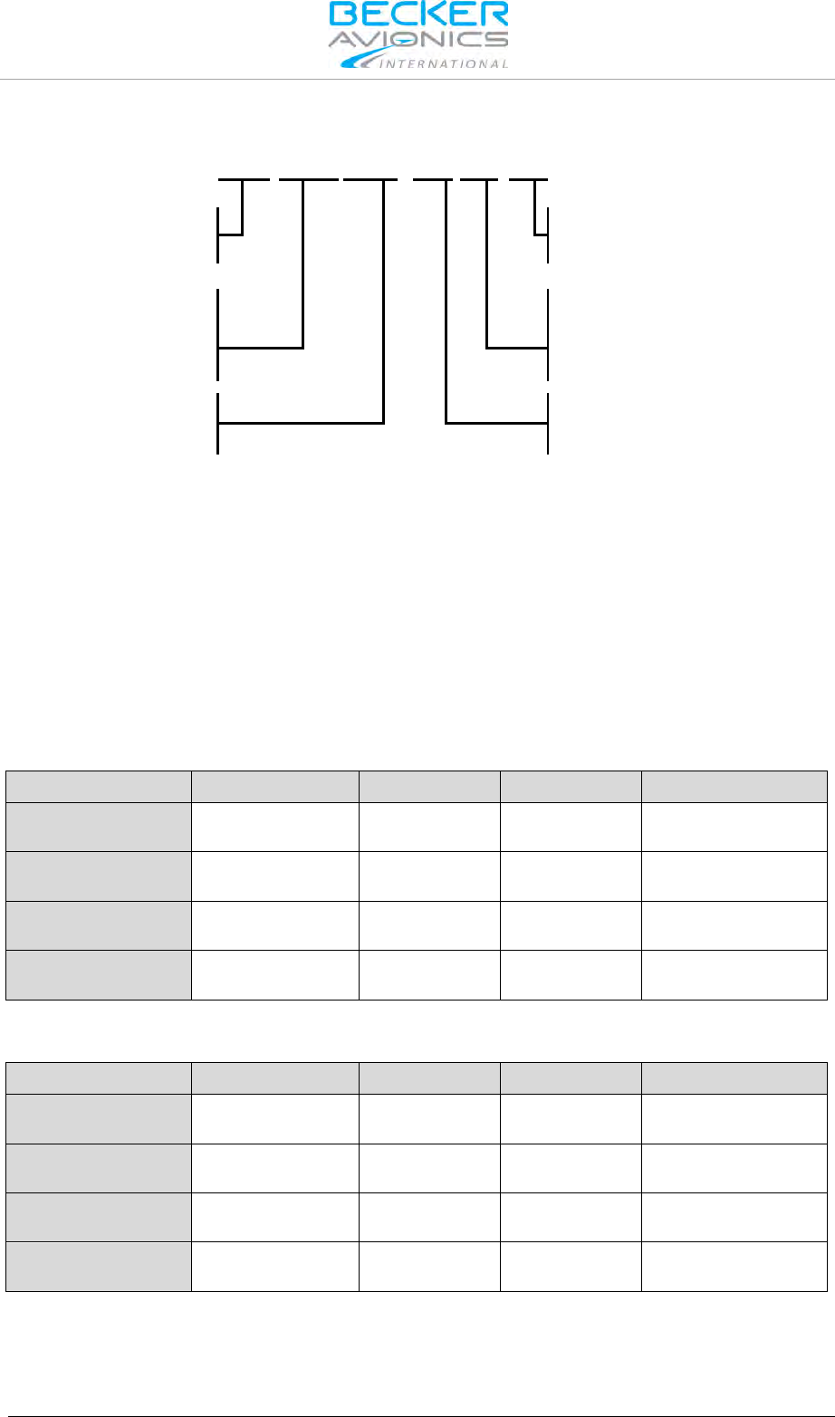
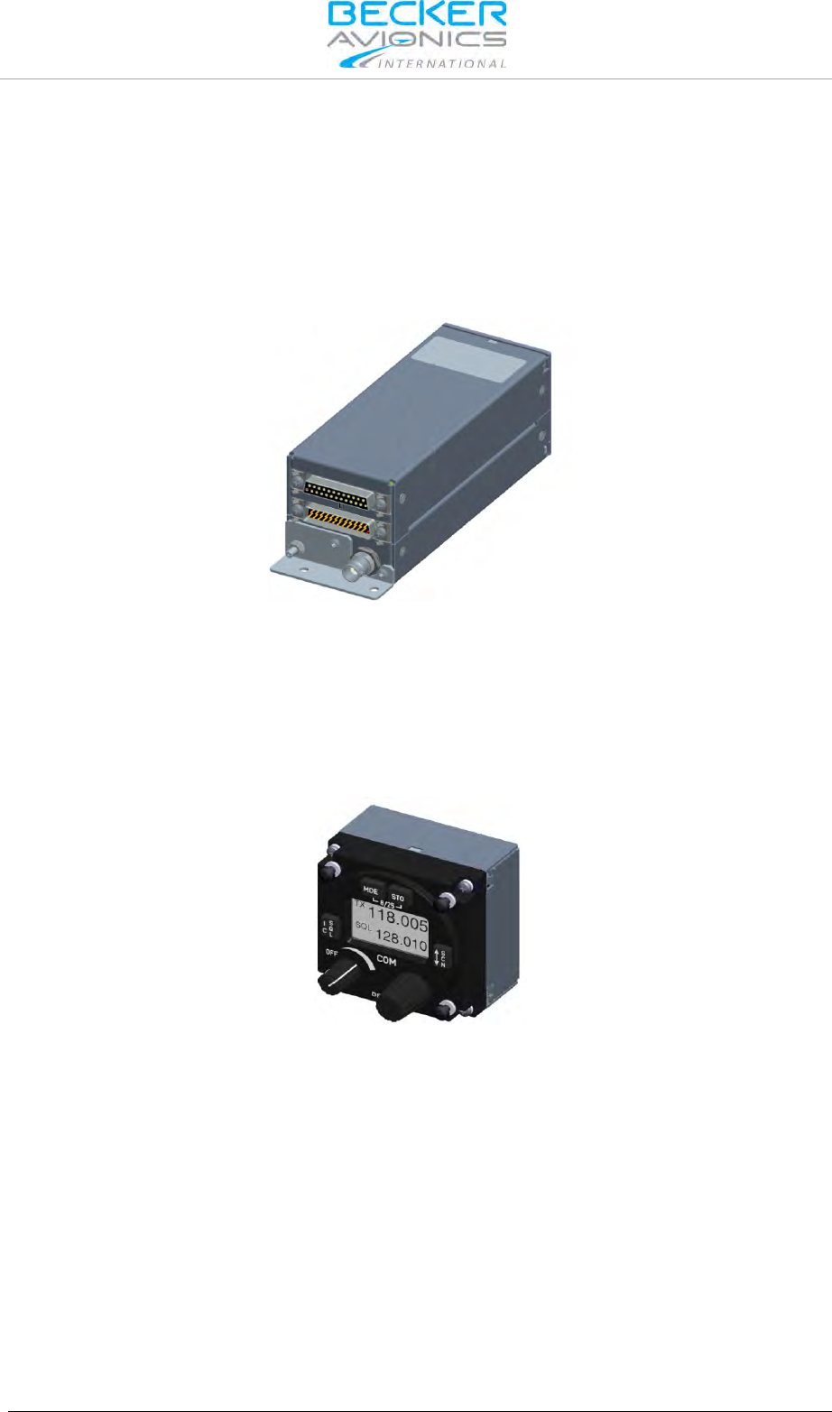
1.5.2. RT6201 Remote Transceiver
The RT6201 is a compact and lightweight single block unit in rectangular shape that contains a
VHF transceiver. The RT6201 requires a dedicated Remote Control Unit RCU6201 or a third party
controller, e.g. a Multi Function Display (MFD), by means of the Becker proprietary protocol.
Installation via four screws using the attached mounting equipment. The dimensions correspond to the
standard instrument diameter of 58 mm (2¼ inch). To meet the conditions for certification use the
mounting method with mounting kit MK6201-(010).
Figure 1-2: RT6201 Single Block Remote Transceiver
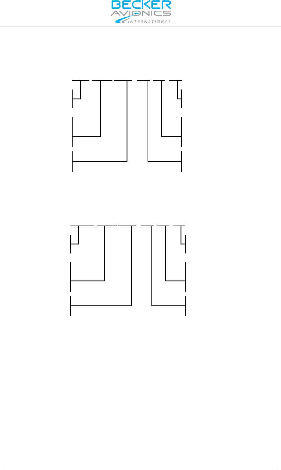
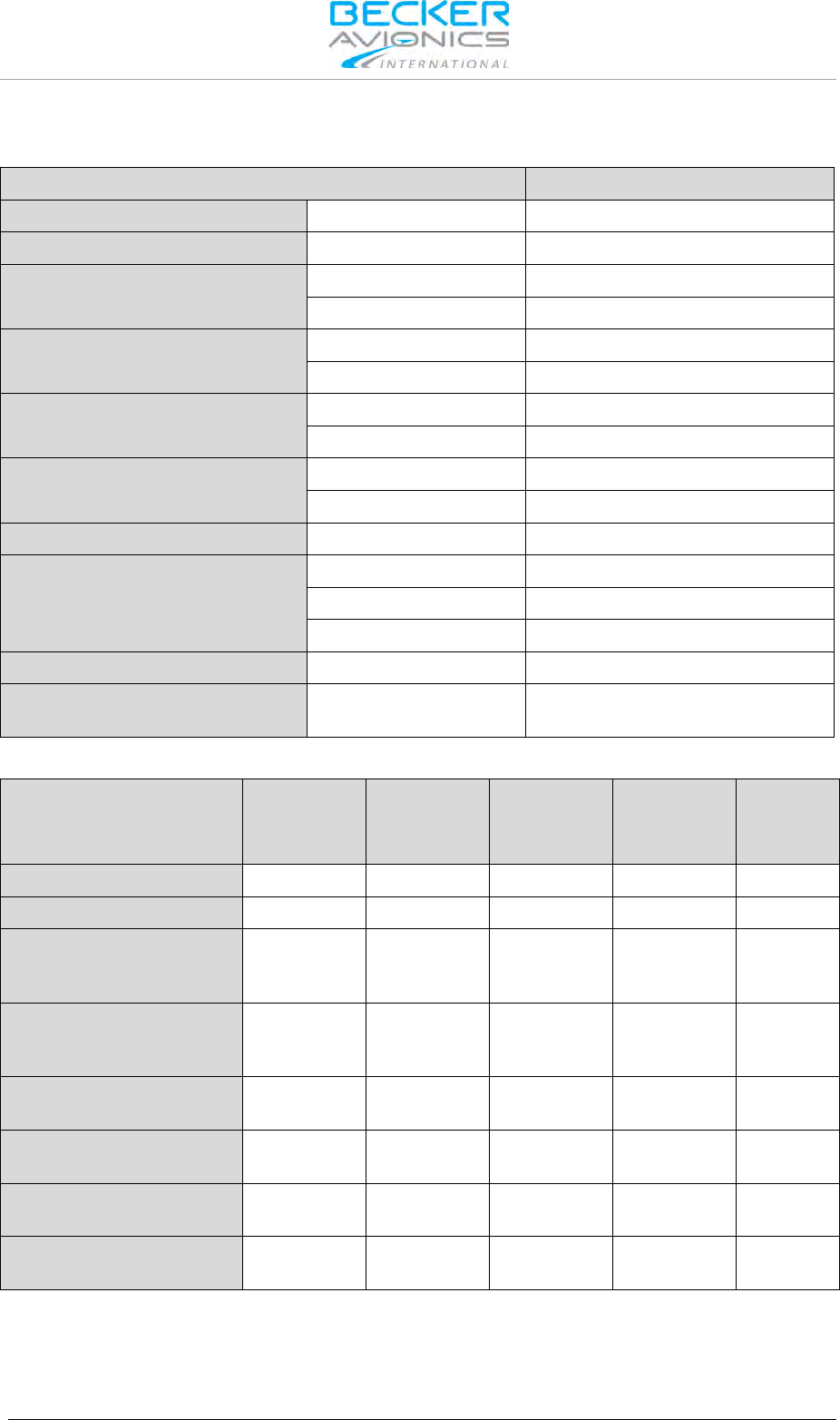
1.5.3. RCU6201 Remote Control Unit
The RCU6201 is a compact and lightweight unit. All controls and indicators are located on the front
panel. The equipment connectors are located at the rear of the unit.
Installation via four screws (rear panel installation). The dimensions correspond to the standard
instrument diameter of 58 mm (2¼ inch).
Figure 1-3: RCU6201 Remote Control Unit

General Description
Features Overview
18 Transceiver Family 620X DV14307.03 Issue 04 March 2016
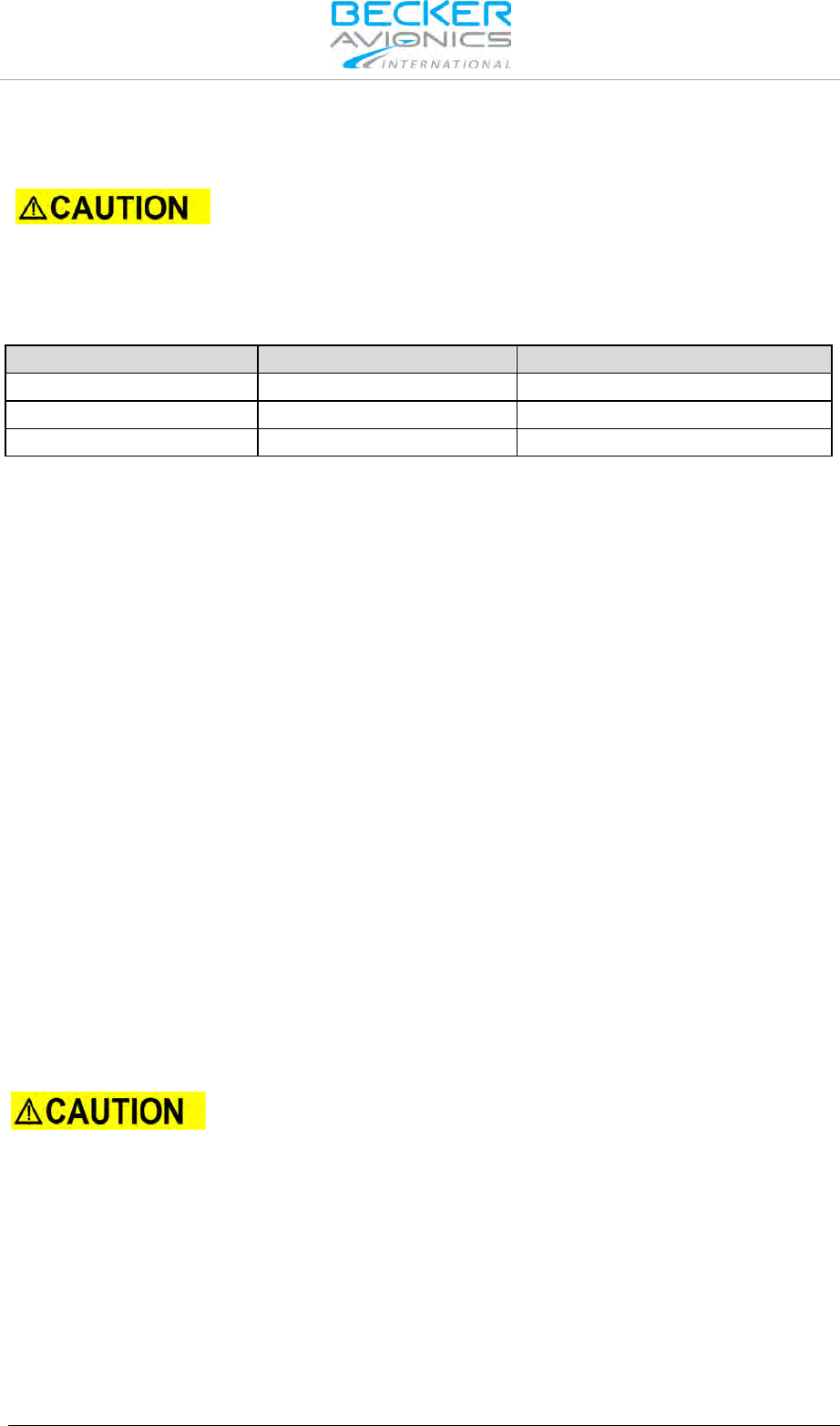
1.5.4. AR6203 Single Block Transceiver
The AR6203 is a single block unit, designed for operation in a cockpit environment for both, general
aviation aircraft and helicopters. All controls and indicators are located on the front panel.
The equipment connectors and the antenna socket are located at the rear of the unit.
The AR6203 should be mounted with the designated mounting kit MK6403-1 (see "AR6203
Installation", page 39). Holes on both sides of the mounting kit frame enable the device been mounted
in the aircraft cockpit.
The dimensions correspond to the state-of-the-art 160 mm (6.3") panel mounted design.
Figure 1-4: AR6203 Single Block Transceiver
1.6. Features Overview
Frequency Indication
A liquid crystal display (LCD) provides frequency indication. The required operating frequency is
selectable by means of a "ROTARY ENCODER". The relation between the real operating frequency
and the displayed frequency complies with the standards (ED-23B, chapter 1.3.2). For an overview,
refer to the table below.
Operating Frequency
MHz
Channel Spacing
kHz
Displayed Frequency
8.33 + 25 kHz
mixed Mode 25 kHz Mode
118.0000 25 118.000 118.00
118.0000 8.33 118.005 N/A
118.0083 8.33 118.010 N/A
118.0166 8.33 118.015 N/A
118.0250 25 118.025 118.02
etc. etc. etc. etc.
136.9750 25 136.975 136.97
136.9750 8.33 136.980 N/A
136.9833 8.33 136.985 N/A
136.9916 8.33 136.990 N/A

General Description
Features Overview
DV14307.03 Issue 04 March 2016 Transceiver Family 620X 19
Audio Outputs
The 620X transceiver includes four fully configurable outputs:
• Headphone 1 output, rated output power is 300 mW into 75 Ω.
• Headphone 2 output, rated output power is 200 mW into 75 Ω.
• Speaker output, rated output power is 4 W into 4 Ω.
• LINE-OUT output intended for ground station use only
Note: Headphone 2 and speaker output cannot be active at the same time
Mike Inputs
The VHF transceiver has an input for dynamic microphone (DYN_MIKE) and an input for standard
microphone (STD_MIKE).
The 620X transceiver provides four microphone inputs:
• Standard microphone input 1 (STD_MIKE1)
• Standard microphone input 2 (STD_MIKE2)
• Standard microphone input 3 (STD_MIKE3)
• Dynamic microphone input (DYN_MIKE)
Each input is able to operate with one single microphone or with two microphones of the same type
connected in parallel.
AF Auxiliary Input
The AF auxiliary provides the interface to connect an external audio source (e.g. NAV, music-player)
to the transceiver. Interconnection of multiple external audio sources on this particular port requires
additional external decupling/isolation resistors. The external audio is audible only when the
transceiver is in receiving mode.
The individual audio volume is set directly at the particular external equipment.
Side Tone
The side tone is available on the headphone output during transmission. The side tone volume
automatically adapts to the intercom volume setting.
Squelch Operation
When enabled the squelch (muting) circuit suppresses weak signals. There are two kinds of squelch
methods implemented, carrier- and noise-squelch. Carrier-squelch depends on the received signal
strength and is adjustable in configuration setup; the noise-squelch depends on the detected noise
level and is adjustable in the user menu.
Memory Channels
The memory function allows storage of up to 99+9 frequencies. A user defined text label is assignable
for each stored frequency. Additionally the last recently used 9 (active) frequencies are stored
automatically as "LAST" channels.
Intercom Operation
The built-in intercom circuit provides internal communication via between pilots and passengers via
connected headsets. The 620X system has two intercom circuits, "Front row" and "Back row". You can
connect a maximum of four headsets, e.g. pilot & co-pilot to first circuit and two passengers to second
circuit).
Scan Mode
Scan mode provides a dual watch function. The device is capable of monitoring frequencies on two
different channels, active & preset simultaneously. The signal of the active frequency will always be
audible, since it will have priority at all times.

General Description
Features Overview
20 Transceiver Family 620X DV14307.03 Issue 04 March 2016
Tandem Operation
Tandem mode enables operation of two controllers simultaneously. The controllers synchronizing
each other in such a way, that both display the same information.
Illumination
The illumination of LCD and push buttons can be controlled either directly from the front panel via the
user menu or externally via the dimming input lines. If external dimming selected, the illumination
curve (brightness to voltage relation) is adjustable in configuration setup.
LOW BATT Indication
The transceiver monitors power supply voltage. If the supply voltage drops below the adjustable
threshold, the display indicates the message "LOW BATT". If the power supply voltage drops further,
emergency operation mode activates.
Emergency Operation
If the power supply voltage drops below 10.25 V, the transceiver continues operation with degraded
performance. If power supply further drops below 9.0 Volt, the unit automatically switches off.
Built-in Tests PBIT and CBIT
After power-up, the unit performs a self-test (power-up built-in test / PBIT). During PBIT, the
transceiver displays "WAIT" and additionally the corresponding software versions of both, the control
head (CH) and core module (CM) become visible.
If faults are detected during PBIT, the error message "FAILURE, press any key" is displayed. If no
faults are detected the transceiver automatically activates the last active mode set at last power-off.
During normal operation, a continuous built-in test (CBIT) permanently verifies the correct operation of
the unit. If detecting a problem during CBIT an error message become displayed.
Configuration Setup
Configuration of parameters such as mike sensitivity, mike type selection, speaker enable/disable and
several other parameters, via the configuration setup provided.
Service Mode
The service mode is a special configuration mode accessible via RS422 interface with a proprietary
serial data communication protocol. This mode is for use by authorized maintenance organizations
during aircraft service on ground only.
General Description
Technical Data
DV14307.03 Issue 04 March 2016 Transceiver Family 620X 21
1.7. Technical Data
620X
Variants
Nominal supply voltage range
11.0…30.3 V
all variants
Extended supply voltage range
10.25…32.2 V
all variants
Emergency operation
9.0...10.25 V
all variants
Dimming control
0…14 V or 0…28 V
all variants
Frequency range
118.000...136.975 MHz
(-1XX variant)
118.000...136.9916 MHz
(-0XX variant)
Channel spacing
25 kHz
(-1XX variant)
8.33/25 kHz
(-0XX variant)
Number of channels
760
(-1XX variant)
2280 +760
(-0XX variant)
Storage Temperature range
-55...+85 °C
all variants
Operating Temperature range
-20...+55 °C
AR620X-(XXX), RCU6201-(XXX)
-40...+55 °C
RT6201-(XXX)
short-time +70 °C
all variants
Operating Altitude
35 000 ft
Vibration
Category S (Curve M) +
Category U (Curve G)
Typical Power Consumption
AR620X
(X2X)
6 W
AR620X
(X1X)
10 W
RT6201
(X2X)
6 W
RT6201
(X1X)
10 W
RCU6201
(XXX)
Power "off" @ 12 VDC
≤ 0.10 mA
≤ 0.10 mA
≤ 0.10 mA
≤ 0.10 mA
≤ 0.10 mA
Power "off" @ 27.5 VDC
≤ 0.10 mA
≤ 0.10 mA
≤ 0.10 mA
≤ 0.10 mA
≤ 0.10 mA
Reception stand-by mode
@ 13.75 VDC,
panel backlight off
≤ 140 mA ≤ 140 mA ≤ 120 mA ≤ 120 mA ≤ 20 mA
Reception stand-by mode
@ 27.5 VDC,
panel backlight off
≤ 80 mA ≤ 80 mA ≤ 80 mA ≤ 80 mA ≤ 20 mA
Transmit mode (in %)
@ 13.75 VDC, VSWR=1:1
1.8 A at 70%
1.5 A at 0% -
1.8 A at 70%
1.5 A at 0% - ≤ 0 mA
Transmit mode
@ 27.5 VDC, VSWR=1:1
1.2 A at 70%
1.0 A at 0%
1.4 A at 70%
1.0 A at 0%
1.2 A at 70%
1.0 A at 0%
1.4 A at 70%
1.0 A at 0% ≤ 20 mA
Absolute maximum current
@ 13.75 VDC, VSWR=3:1 ≤ 3 A - ≤ 2,9 A - ≤ 20 mA
Absolute maximum current
@ 27.5 VDC, VSWR=3:1 ≤ 2 A ≤ 2.5 A ≤ 1.9 A ≤ 2.4 A ≤ 20 mA
General Description
Technical Data
22 Transceiver Family 620X DV14307.03 Issue 04 March 2016
1.7.1. Receiver Data for AR620X and RT6201
Technical characteristics AR620X, RT6201
Sensitivity
≤ -101 dBm for a (S+N)/N ratio of 6 dB (nominal)
≤ -93 dBm for a (S+N)/N ratio of 6 dB (qualified under
environmental conditions)
Effective bandwidth
(8.33 kHz channel spacing)
≥ ±2.78 kHz at the 6 dB points
≤ ±7.37 kHz at the 60 dB points
Effective bandwidth
(25 kHz channel spacing)
≥ ±8 kHz at the 6 dB points
≤ ±22 kHz at the 60 dB points
Squelch
level adjustable
AGC characteristic
≤ 6 dB in range -93 dBm...0
Distortion
≤ 15%
≤ 15% at 70% of rated output power
Audio frequency response
(8.33 kHz channel spacing)
≤ 6 dB 350...2500 Hz
≥ 35 dB at 4000 Hz
Audio Noise
≤ 6 dB 300...3400 Hz
≥ 18 dB at 4000 Hz
Rated output power for speaker operation
≥ 4 W into 4 Ω
Rated output power for headphone 1
≥ 300 mW into 75 Ω
≥ 100 mW into 600 Ω
Rated output power for headphone 2
≥ 200 mW into 75 Ω
≥ 100 mW into 600 Ω
Audio auxiliary input
50 mV...8 V (adjustable) across 600 Ω
Offset-carrier operation
YES (25/8.33 kHz)
General Description
Technical Data
DV14307.03 Issue 04 March 2016 Transceiver Family 620X 23
1.7.2. Transmitter Data AR620X and RT6201
Technical characteristics AR620X, RT6201
Output power into 50 Ω
(with and without modulation)
≥ 6 W for AR620X-(X2X) and RT6201-(X2X)
≥ 10 W for AR620X-(X1X) and RT6201-(X1X)
Frequency tolerance
≤ ±5 ppm
Duty cycle
120 s (TX): 480 s (RX)
Type of modulation
A3E
Modulation capability
≥ 70%
Distortion
≤ 15%
Audio frequency response
(8.33 kHz channel spacing)
≤ 6 dB, 350...2500 Hz
Audio frequency response
(25 kHz channel spacing)
≤ 6 dB, 300...2500 Hz
Dynamic microphone
1…20 mV compressor starting point, adjustable
(with compressor)
Input balanced, 200 Ω
Input range up to 20 dB above compressor starting
point.
Standard microphone(s)
10…1000 mV compressor starting point, adjustable
(with compressor)
Input unbalanced, 150 Ω
Input range up to 20 dB above compressor starting
point.
FM deviation with modulation
≤ 3 kHz
Sidetone
adjustable
PTT stuck detection of transmit mode
120 s
(Factory configurable 30…120 s)
General Description
Technical Data
24 Transceiver Family 620X DV14307.03 Issue 04 March 2016
1.7.3. Dimensions & Weight
AR6201-(XXX)
AR6203-(XXX)
RCU6201-(XXX)
RT6201-(XXX)
Front panel
(W x H)
61 x 61 mm
(2.4 x 2.4 inch)
158.8 x 41.2 mm
(6.25 x 1.62 inch)
61 x 61 mm
(2.4 x 2.4 inch)
61 x 61 mm
(2.4 x 2.4 inch)
Depth of unit
205.7 mm
(8.98 inch)
224.4 mm
(8.83 inch)
65.9 mm
(2.59 inch)
188 mm
(7.4 inch)
Mounting depth
184.8 mm
(7.28 inch)
224.4 mm
(8.83 inch)
39.3 mm
(1.55 inch)
188 mm
(7.4 inch)
Mounting
Back panel standard
Ø58 mm (2¼ inch)
Mounting kit
MK6403-1
panel mount
160 mm (6.3 inch)
Back panel standard
Ø58 mm (2¼ inch)
Mounting kit
MK6201-(010)
or directly on
avionic bay*
Material
AlMg/Plastic
AlMg/Plastic
AlMg/Plastic
AlMg
Surface
treatment Control-head coated with black matt paint
Weight
675 g
(1.488 lbs)
800 g
(1.763 lbs)
200 g
(0.44 lbs)
600 g
(1.32 lbs)
Note:
*Use the mounting method with mounting kit to meet the conditions for certification.
1.7.4. Emergency Operation
For power-supply voltages below 10.25 V, the speaker output of the
transceiver will automatically switch "OFF" without further indication.
If the device enters emergency operation, the speaker is switched "OFF" due to degraded
performance. Depending on settings in configuration setup "LOW BATT" may be indicated if supply
voltage drops below a predefined threshold to indicate to the user, that he should connect his headset
as the speaker may be switched "OFF" soon). In this case, a headset is required to continue operation
of the transceiver. This data is applicable for AR620X and RCU6201.
Technical characteristics
Panel & Display Backlight
switched off
TX Output Power
≥ 2 W into 50 Ω (with modulation)
TX Modulation Depth
≥ 50%
RX Sensitivity
≤ -93 dBm for a (S+N)/N ratio of 6 dB
1.7.5. Environmental Qualification AR620X and RCU6201
Under environmental test, condition in accordance with the procedures set forth in EUROCAE/RTCA
Document ED-14F/DO-160F following performance has been demonstrated.
Condition
Section
Cat.
Description
Temperature and Altitude
4.0
C4
Ground Survival Low Temperature
4.5.1 C4
-55 °C
Short-Time Operating Low Temperature
-20 °C
Low Operating Temperature
-20 °C

General Description
Technical Data
DV14307.03 Issue 04 March 2016 Transceiver Family 620X 25
Condition
Section
Cat.
Description
High Ground Survival Temperature
4.5.2
+85 °C
High Short-Time Operating Temp.
+70 °C
High Operating Temp.
+55 °C
In-flight Loss of Cooling
4.5.5
-
No forced cooling required
Altitude
4.6.1
C4
35000 ft
Decompression
4.6.2
N/A
Overpressure
4.6.3
N/A
Temperature Variation
5.0
B
5 °C per minute
Humidity
6.0
A
Standard
Shock and Crash Safety
7.0
B
Fixed-wing and Helicopter, standard
Vibration 8.0 S+U
Test curve M+G Fixed-wing +
Helicopter
Explosion Proofness
9.0
-
N/A
Water Proofness
10.0
Y
-
Fluids Susceptibility
11.0
-
N/A
Sand and Dust
12.0
-
N/A
Fungus Resistance
13.0
-
N/A
Salt Spray
14.0
-
N/A
Magnetic Effect
15.0
Z
1 degree deflection at 0.3 m
Power Input 16.0 B
DC installations with battery of
significant capacity
Voltage Spike 17.0 A
High degree of protections against
voltage spikes
Audio Freq. Conducted Susceptibility 18.0 B
DC installations with battery of
significant capacity
Induced Signal Susceptibility
19.0
AC
Primary power DC or AC, 400 Hz
Radio Frequency Susceptibility
20.0
RW
Interim high intensity radiated fields
Emission of Radio Frequency Energy 21.0 B
Equipment where interference should
be controlled to a tolerable level
Lightning Induced Transients
Susceptibility 22.0 A1E3X
Pin test waveform A, level 3
Cable bundle test waveform E, level 3
Lightning Direct Effects
23.0
-
N/A
Icing
24.0
-
N/A
Electrostatic Discharge 25.0 A
Equipment operated in an aerospace
environment
Fire, Flammability
26.0
-
N/A

General Description
Technical Data
26 Transceiver Family 620X DV14307.03 Issue 04 March 2016
1.7.6. Environmental Qualification RT6201
Under environmental test, condition in accordance with the procedures set forth in EUROCAE/RTCA
Document ED-14F/DO-160F following performance has been demonstrated.
Condition
Section
Cat.
Description
Temperature and Altitude
4.0
C4
Ground Survival Low Temperature
4.5.1
C4
-55 °C
Short-Time Operating Low Temperature
-40 °C
Low Operating Temperature
-40 °C
High Ground Survival Temperature
4.5.2
+85 °C
High Short-Time Operating Temp.
+70 °C
High Operating Temp.
+55 °C
In-flight Loss of Cooling
4.5.5
-
No forced cooling required
Altitude
4.6.1
C4
3500 ft
Decompression
4.6.2
N/A
Overpressure
4.6.3
N/A
Temperature Variation
5.0
B
5 °C per minute
Humidity
6.0
A
Standard
Shock and Crash Safety
7.0
B
Fixed-wing and Helicopter, standard
Vibration 8.0 S+U
Test curve M+G fixed-wing +
helicopter
Explosion Proofness
9.0
-
N/A
Water Proofness
10.0
Y
N/A
Fluids Susceptibility
11.0
-
N/A
Sand and Dust
12.0
-
N/A
Fungus Resistance
13.0
-
N/A
Salt Spray
14.0
-
N/A
Magnetic Effect
15.0
Z
1 degree deflection at 0.3 m
Power Input 16.0 B
DC installations with battery of
significant capacity
Voltage Spike 17.0 A
High degree of protections against
voltage spikes
Audio Freq. Conducted Susceptibility 18.0 B
DC installations with battery of
significant capacity
Induced Signal Susceptibility
19.0
AC
Primary power DC or AC, 400 Hz
Radio Frequency Susceptibility 20.0 SW
Interim High Intensity Radiated
Fields
Emission of Radio Frequency Energy 21.0 B
Equipment where interference
should be controlled to a tolerable
level
Lightning Induced Transients
Susceptibility 22.0 A1E3X
Pin test waveform A, level 3
Cable bundle test waveform E,
level 3

General Description
Technical Data
DV14307.03 Issue 04 March 2016 Transceiver Family 620X 27
Condition
Section
Cat.
Description
Lightning Direct Effects
23.0
-
N/A
Icing
24.0
-
N/A
Electrostatic Discharge 25.0 A
Equipment operated in an
aerospace environment
Fire, Flammability
26.0
-
N/A
1.7.7. Software
The design and development processes used for AR6201 family software are in compliance with the
rules given in EUROCAE/RTCA Document ED-12B/DO-178B; “Software Considerations in Airborne
System and Equipment Certification”. Hereby ‘Design Assurance Level’ (DAL) “C” was followed and
the complete software documentation is based on this level.
Nevertheless, Becker claimed for AR6201 family software in accordance with EUROCAE/RTCA
Document ED-12B/DO-178B the Design Assurance Level D.
Refer to AC 23.1309-1D and/or AC 23.1309-1E to see limitations for installations into aircrafts.
The conditions and tests required for TSO approval of this article are minimum performance
standards. It is the responsibility of those installing this article either on or within a specific type or
class of aircraft to determine that the aircraft installation conditions are within the TSO standards. TSO
articles must have separate approval for installation in an aircraft. The article may be installed only in
compliance with 14 CFR part 43 or the applicable airworthiness requirements.
1.7.8. Complex Hardware
The 620X devices do not contain complex hardware.

General Description
Technical Data
28 Transceiver Family 620X DV14307.03 Issue 04 March 2016
1.7.9. Approvals
Unauthorized changes or modifications to the 620X transceiver may
void the
compliance to the required regulatory agencies and
authorization for continued equipment usage.
AR6201 Single Block Transceiver
Part Number Article Number EASA Approval TSO Conformity FCC Approval
AR6201-(012) 0631.418-910
EASA.21O.1249
ETSO-2C37e
Class: D, E
ETSO-2C38e
Class: 4, 6
TSO-C169a
Class: D, E, 4, 6 B54AR6201
AR6201-(112) 0631.434-910
EASA.21O.1249
ETSO-2C37e Class: D
ETSO-2C38e Class: 4
TSO-C169a
Class: D, 4 B54AR6201
AR6201-(022) 0636.339-910
EASA.21O.1249
ETSO-2C37e
ETSO-2C38e
Class: D, E, 4, 6
TSO-C169a
Class: D, E, 4, 6 B54AR6201
AR6201-(122) 0636.355-910
EASA.21O.1249
ETSO-2C37e Class: D
ETSO-2C38e Class: 4
Class: D, 4
TSO-C169a
Class: D, 4 B54AR6201
RT6201 Remote Transceiver
Part Number Article Number EASA Approval TSO Conformity FCC Approval
RT6201-(010) 0631.442-910 EASA.21O.1249
ETSO-2C37e
Class: D, E
ETSO-2C38e
Class: 4, 6
TSO-C169a
Class: D, E, 4, 6 pending
RT6201-(020) 0636.312-910
RCU6201 Remote Control Unit
Part Number Article Number EASA Approval
TSO
Conformity FCC Approval
RCU6201-(012) 0631.469-910
EASA.21O.1249
ETSO-2C37e
Class: D, E
ETSO-2C38e
Class: 4, 6
TSO-C169a
Class: D, E, 4, 6 B54AR6201
RCU6201-(112) 0631.485-910
EASA.21O.1249
ETSO-2C37e Class: D
ETSO-2C38e Class: 4
TSO-C169a
Class: D, 4 B54AR6201

General Description
Technical Data
DV14307.03 Issue 04 March 2016 Transceiver Family 620X 29
AR6203 Single Block Transceiver
Part Number Article Number EASA Approval TSO Conformity FCC Approval
AR6203-(012) 0630.993-910
EASA.21O.10054849
ETSO-2C169a
Class: C, H2, 4, 6
TSO-C169a
Class: D, E, 4, 6 pending
AR6203-(112) 0631.566-910
EASA.21O.10054849
ETSO-2C169a
Class: C, 4
TSO-C169a
Class: C, 4 pending
AR6203-(022) 0636.371-910
EASA.21O.10054849
ETSO-2C169a
Class: C, H2, 4, 6
TSO-C169a
Class: D, E, 4, 6 pending
AR6203-(122) 0636.398-910
EASA.21O.10054849
ETSO-2C169a
Class: C, 4
TSO-C169a
Class: C, 4 pending
1.7.9.1. FCC Approval
Radiofrequency radiation exposure information:
This equipment complies with FCC radiation exposure limits set forth for an uncontrolled environment.
This equipment should be installed and operated with minimum distance of 50 cm between the
radiator and your body.
This transmitter must not be co-located or operating in conjunction with any other antenna or
transmitter.
NOTE:
This equipment has been tested and found to comply with the limits for a Class A digital device,
pursuant to Part 15 of the FCC Rules. These limits are designed to provide reasonable protection
against harmful interference when the equipment is operated in a commercial environment. This
equipment generates, uses, and can radiate radio frequency energy and, if not installed and used in
accordance with the instruction manual, may cause harmful interference to radio communications.
Operation of this equipment in a residential area is likely to cause harmful interference in which case
the user will be required to correct the interference at his own expense.
NOTE:
This device complies with Part 15 of the FCC Rules [and with Industry Canada licence-exempt
RSS standard(s)].
Operation is subject to the following two conditions:
• This device may not cause harmful interference, and
• This device must accept any interference received, including interference that may cause
undesired operation.
NOTE:
Changes or modifications made to this equipment not expressly approved by Becker Avionics may
void the FCC authorization to operate this equipment.
General Description
Order Code
30 Transceiver Family 620X DV14307.03 Issue 04 March 2016
1.8. Order Code
1.8.1. 620X
Qty
AR6201 Single Block Transceiver
1
AR6201-(012), 8.33/25 kHz, 10 W at 28 V
Article no. 0631.418-910
1
AR6201-(022), 8.33/25 kHz, 6 W at 12 V
Article-no. 0636.339-910
1
AR6201-(112), 25 kHz, 10 W at 28 V
Article-no. 0631.434-910
1
AR6201-(122), 25 kHz, 6 W at 12 V
Article-no. 0636.355-910
Qty
RT6201 Remote Transceiver
1
RT6201-(010), 8.33/25 kHz, 10 W at 28 V
Article no. 0631.442-910
1
RT6201-(020), 8.33/25 kHz, 6 W at 12 V
Article-no. 0636.312-910
1
RT6201–(110), 25 kHz, 10 W at 28 V
Article-no. 0638.609-910
1
RT6201-(120), 25 kHz, 6 W at 12 V
Article-no. 0638.617-910
Qty
RCU6201 Remote Control Unit
1
RCU6201-(012), 8.33/25 kHz
Article no. 0631.469-910
1
RCU6201-(112), 25 kHz
Article-no. 0631.485-910
Qty
AR6203 Single Block Transceiver
1
AR6203-(012), 8.33/25 kHz, 10 W at 28 V
Article no. 0630.993-910
1
AR6203-(022), 8.33/25 kHz, 6 W at 12 V
Article-no. 0636.371-910
1
AR6203-(112), 25 kHz, 10 W at 28 V
Article-no. 0631.566-910
1
AR6203-(122), 25 kHz, 6 W at 12 V
Article-no. 0636.398-910
1.8.2. Accessories
Qty
Connector Kit
1
CK4201-S (soldering version);
• Dsub 25-s, Connector housing, Antenna plug, Label
"COMM"
Article no. 0879.304-954
1
CK4201-C (crimp version);
• Dsub 25-c, Connector housing, Antenna plug, Label
"COMM"
Article no. 0514.901-954
1
CK6000-S (soldering version);
• Dsub Connector LE M 25pol, Connector housing
Article no. 0640.621-954
1
CK6000-C (crimp version);
• Dsub Connector LE M 25pol, Connector housing
Article no. 0640.611-954
1
CK6200-S (soldering version);
• Dsub25-s, Dsub25-p,2 Connector housings, Antenna
plug, Label "COMM"
Article no. 0617.903-954
General Description
Order Code
DV14307.03 Issue 04 March 2016 Transceiver Family 620X 31
Qty
Connector Kit
1
CK6200-C (crimp version);
• Dsub25-s, Dsub25-p,2 Connector housings, Antenna
plug, Label "COMM", Coding key
Article no.0617.891-954
1
CK5000-S (soldering version);
• Dsub15-s, Connector housing, Label "COMM", Label
"NAV", Label "ADF", Label "XPDR"
Article no. 0511.791-954
1
CK5000-C (crimp version);
• Dsub25-s, Connector housing, Label "COMM", Label
"NAV", Label "ADF", Label "XPDR"
Article no. 0511.781-954
Qty
Cable harness
1
1K062 Cable harness AR62XX (open cable ends), length 3.7 m,
for sailplanes, motor gliders, to be used for:
• Headphone
• Dynamic microphone
• Speaker
• PTT switch
• Power supply
Article no. 0621.390-950
1
1K065 Cable harness AR62XX (prepared with connectors),
length 3.7 m, for general aviation, to be used for:
• 2x Phone, jack socket PJ55
• 2x Standard microphone, jack socket PJ68
• 1x PTT switch
• 1x Audio in, jack socket 3.5 mm
• 1x Power supply
Article no. 0621.455-950
For details please refer to "Predesigned Cable Harness", page 89.
Qty
Mounting
1
Mounting Kit MK6201-(010)
Article no. 0631.515-261
1
Mounting Kit MK6403-1
Article no. 0598.569-284
1
Adapter for AR3201 wiring 1AD042
Article no. 0877.522-959
Qty
Available Documentation
1
Operating Instructions AR620X, RT6201, RCU6201, English
Article no. 0638.420-071
1
Operating Instructions AR620X, RT6201, RCU6201, German
Article no. 0641.413-071
1
Manual Installation and Operation 620X Family, English
Article no. 0638.404-071

General Description
Order Code
32 Transceiver Family 620X DV14307.03 Issue 04 March 2016
Blank Page

Installation
Limitations
DV14307.03 Issue 04 March 2016 Transceiver Family 620X 33
2. Installation
This manual must be available close to the device during the performance of all tasks.
The installation of the transceiver depends on the type of aircraft and its equipment. Therefore, this
section only provides general information.
Careful planning should be applied to achieve the desired performance and reliability from the product.
Any deviations from the installation instructions prescribed in this document shall be accomplished in
accordance with the requirements set forth in FAA AC 43 (Federal Aviation Administration, Advisory
Circular).
In this chapter you can read about:
2.1. Limitations ................................................................................................................................... 33
2.2. Packaging, Transport, Storage ................................................................................................... 33
2.3. Device Assignment ..................................................................................................................... 34
2.4. Mechanical Installation ................................................................................................................ 36
2.5. Electrical Interface ....................................................................................................................... 44
2.6. Installation and Configuration ..................................................................................................... 52
2.7. Antenna Installation ..................................................................................................................... 53
2.8. Configuration Setup .................................................................................................................... 53
2.9. Factory Default Settings .............................................................................................................. 68
2.10. Wiring Diagrams and Settings..................................................................................................... 70
2.11. Predesigned Cable Harness ....................................................................................................... 89
2.12. Retrofitting AR4201 with AR6201 ............................................................................................... 89
2.13. Post Installation Tests ................................................................................................................. 92
2.14. Trouble Shooting ......................................................................................................................... 95
2.15. Continued Airworthiness ............................................................................................................. 96
2.1. Limitations
620X design allows installation in cockpit environment of general aviation aircraft including helicopters.
Following limitations apply for the installation of the unit:
• Installations must be in accordance with appropriate EASA or FAA approved guidelines.
The personnel installing this device must ensure that the aircraft installation conditions are
within the ETSO/TSO standards applicable for the specific type or class of aircraft,
• The 620X transceiver must be connecting to a VHF antenna in order to satisfy
FAA TSO-C169a.
• The conditions and tests for ETSO/TSO approval of this article are minimum performance
standards.
• The equipment is not qualified for installation in areas where fluid contamination is quite
likely.
Changes or modifications made to this equipment not expressly
approved in written form by Becker may void the authorization to
operate this equipment.
2.2. Packaging, Transport, Storage
Visually inspect the package contents for signs of transport damage.
Packaging Material and Transport
The packaging material is inflammable, if it is disposed of improperly
by burning, lethal fumes may develop.
The packaging material can be kept and reused in the case of a return shipment. Improper or faulty
packaging may lead to transport damages.

Installation
Device Assignment
34 Transceiver Family 620X DV14307.03 Issue 04 March 2016
Make sure to transport the device always in a safe manner and with the aid of suitable lifting
equipment if necessary. Do never use the electric connections for lifting. Before the transport, a clean,
level surface should be prepared to place the device on. The electric connections may not be
damaged when placing the device.
First Device Checkup
• Check the device for signs of transport damages.
• Please verify if the indications on the type plate correspond to your purchase order.
• Check if the equipment is complete ("Scope of Delivery", page 34).
Storage
If you do not wish to mount and install the device immediately, make sure to store it in a dry and clean
environment. Make sure that the device is not stored near strong heat sources and that no metal
chippings can get into the device.
2.3. Device Assignment
This manual is valid for the following devices:
• AR6201-(XX2)
• AR6203-(XX2)
• RT6201-(XX0) with RCU6201-(X12)
from Software Version
SCI1050S305 Version 4.06
SCI1051S305 Version 2.06
Details see "Variants Overview", page 14
2.3.1. Scope of Delivery
• Manuals
o Operating Instructions.
• Device in accordance with your order.
• Device accessories
• Documents of Certifications if available
2.3.2. Additional Required Equipment
• Mounting kit MK6403-1 (for AR6203)
• Mounting kit MK6201-(10) (for RT6201 to meet the conditions for certification).
• Connector kits.
• Cable harness.
Details see "Order Code" page 30
Installation
Mechanical Installation
DV14307.03 Issue 04 March 2016 Transceiver Family 620X 35
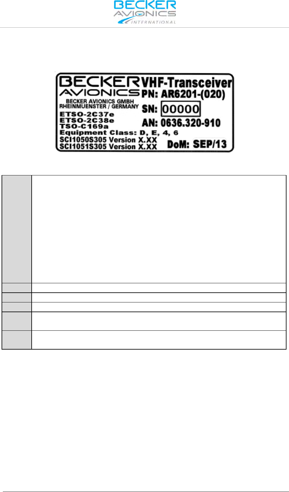
2.3.3. Type Plate
The device type is defined by the type plate (on the housing):
Figure 2-1: Type plate (example)
Explanation:
PN:
Type designation:
AR6201 = Single Block VHF Transceiver 58 mm (2¼ inch)
AR6203 = Single Block VHF Transceiver 160 mm (6.3 inch)
RT6201 = Remote VHF Transceiver
RCU6201 = Remote Control Unit 58 mm (2¼ inch)
Options:
0XX: 8.33/25 kHz channel spacing capability
1XX: 25 kHz channel spacing capability only
X1X: 6 W @ 14 V / 10 W at 28 V
X2X: 6 W @ 14 V
XX2: white illumination colour on black panel
SN:
Unique number of the particular device
AN:
Article number
DoM:
Date of Manufacturing
Software:
Corresponding to the displayed version
Compliance and Certifications
Corresponding to the displayed text and logos
2.3.4. Software/Firmware Status – Functionality
The software version is displayed at the screen for a few seconds after power on.
Please contact our Customer Service for details about software modification updates.

Installation
Mechanical Installation
36 Transceiver Family 620X DV14307.03 Issue 04 March 2016
2.4. Mechanical Installation
The device must not be opened.
When installing the device, make sure the heat dissipators of the
device receive sufficient air. Keep an efficient distance of the devices
with integrated ventilator fans in order to ensure free circulation of the
cooling air.
Make sure that the mounting plate is not exposed to external
temperature influences.
The mounting place shall be at least 30 cm from the magnetic aircraft
compass, to avoid any interference to the magnetic compass (there
are no restrictions for RCU6201mounting).
2.4.1. AR6201 and RCU6201 Installation (Back Panel Mounting)
Leave a clearance of minimum 5 mm between the AR6201 respectively RCU6201 and other avionics
to allow air circulation. Forced cooling is usually not required. For installation via rear side of the panel,
four screws already attach to the front of the unit. The circular cut out and the mounting holes have to
be prepared in accordance with Figure 2-3. For unit dimensions refer to Figure 2-5, Figure 2-4 and
Figure 2-2.
Dimensions mm (inch)
61x61 mm (2.4x2.4 in)
Figure 2-2: AR6201 and RCU6201 front view
Figure 2-3: Drilling template (back-panel mounting)
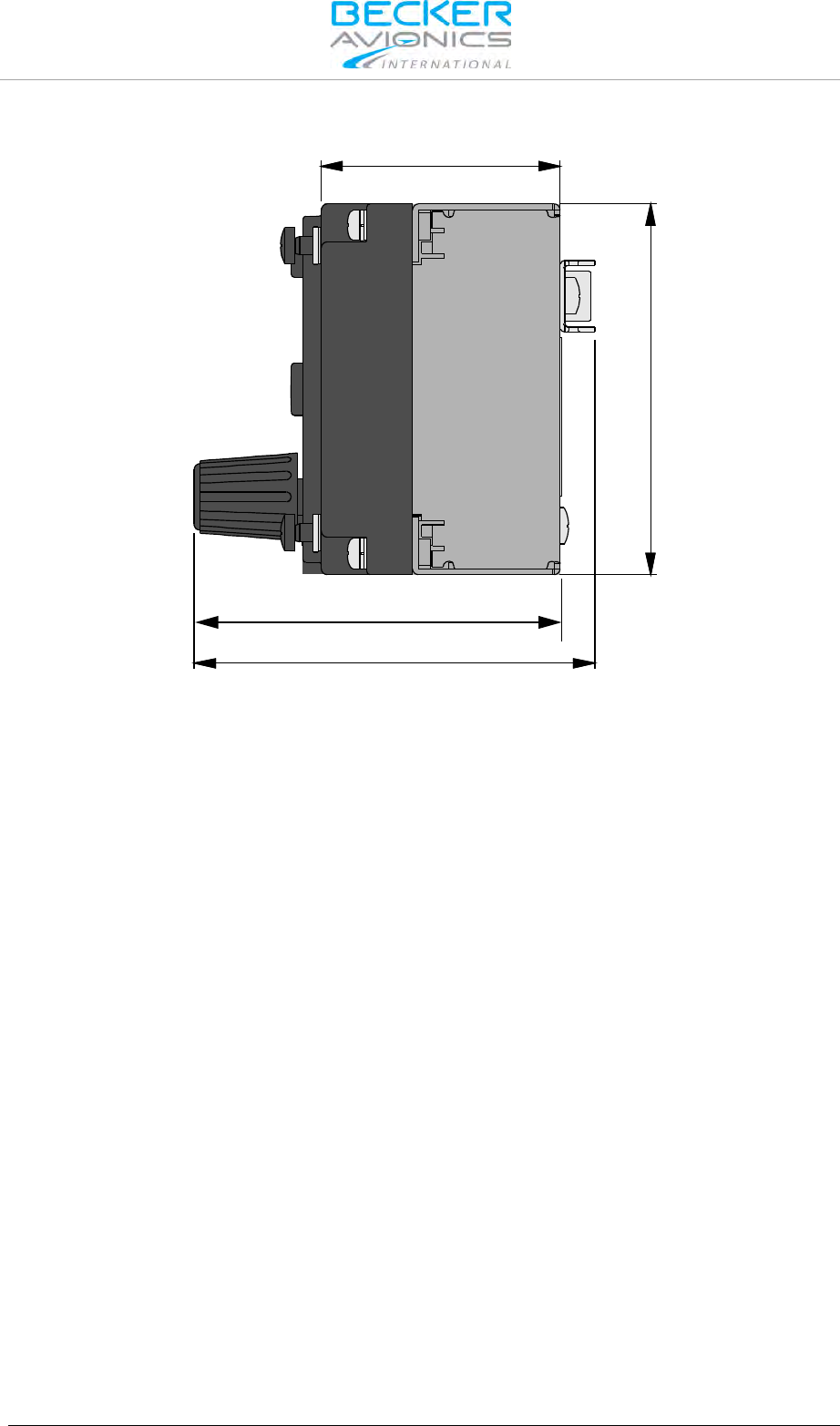
Installation
Mechanical Installation
DV14307.03 Issue 04 March 2016 Transceiver Family 620X 37
Dimensions mm (inch)
39.3
(1.55 in)
61 (2.4 in)
65.9±0.4 (2.59 in ±0.015)
60.2±0.4 (2.37 in ±0.015)
Figure 2-4: RCU6201 side view
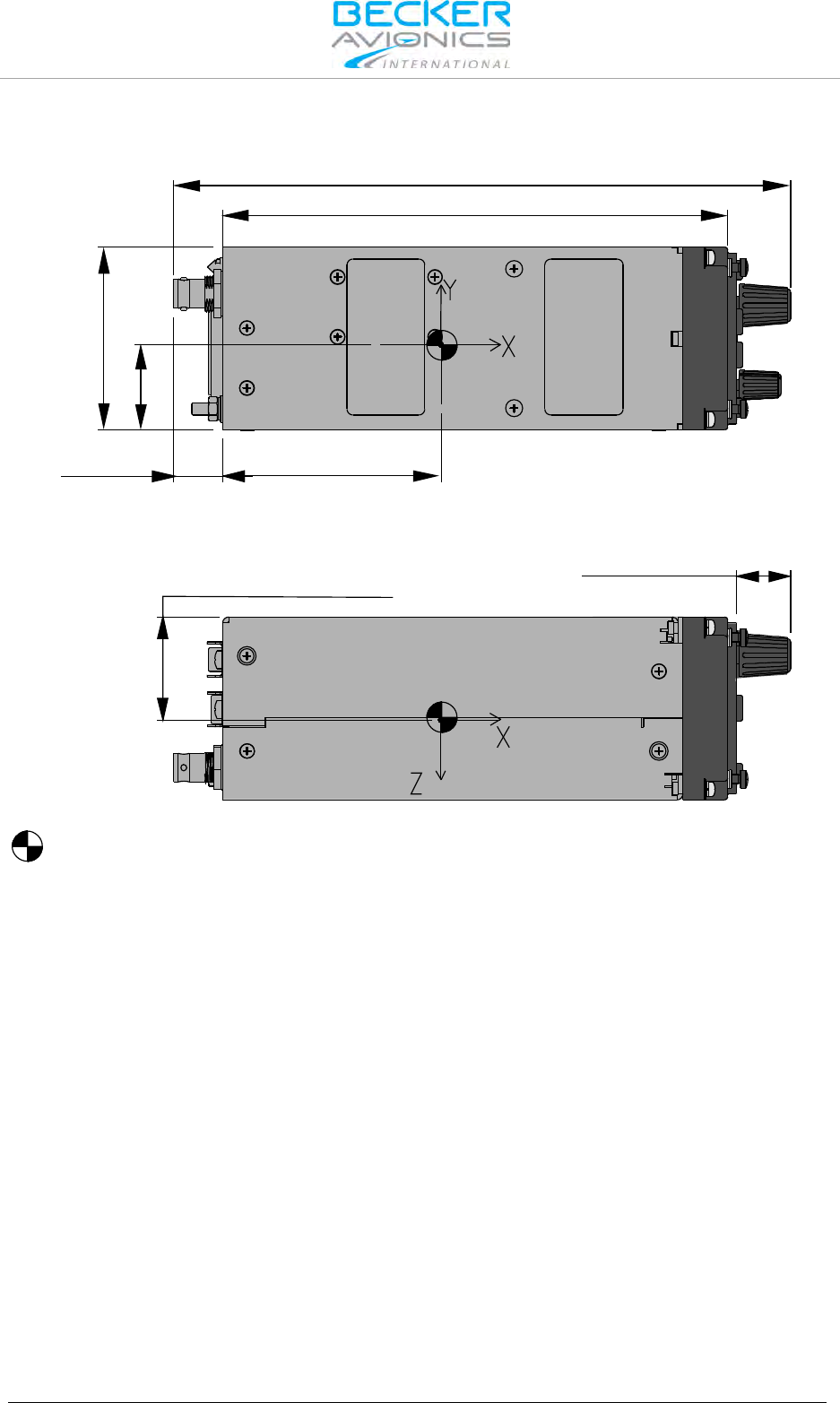
Installation
Mechanical Installation
38 Transceiver Family 620X DV14307.03 Issue 04 March 2016
Dimensions mm (inch)
CENTER OF GRAVITY
61 (2.4 in)
28.5±3 (1.12 in)
16.4 ±0.5
(0.65 in ±0.02)
205.7 ±1.5 (8.098 in ±0.059)
CG
168.4 ±0.8 (6.63 in ±0.031)
72.6 ±5
(2.86 in ±0.2)
CG
17.9 ±0.4
(0.70 in ±0.016)
34.4±3 (1.35 in ±0.12)
Figure 2-5: AR6201 top view, side view
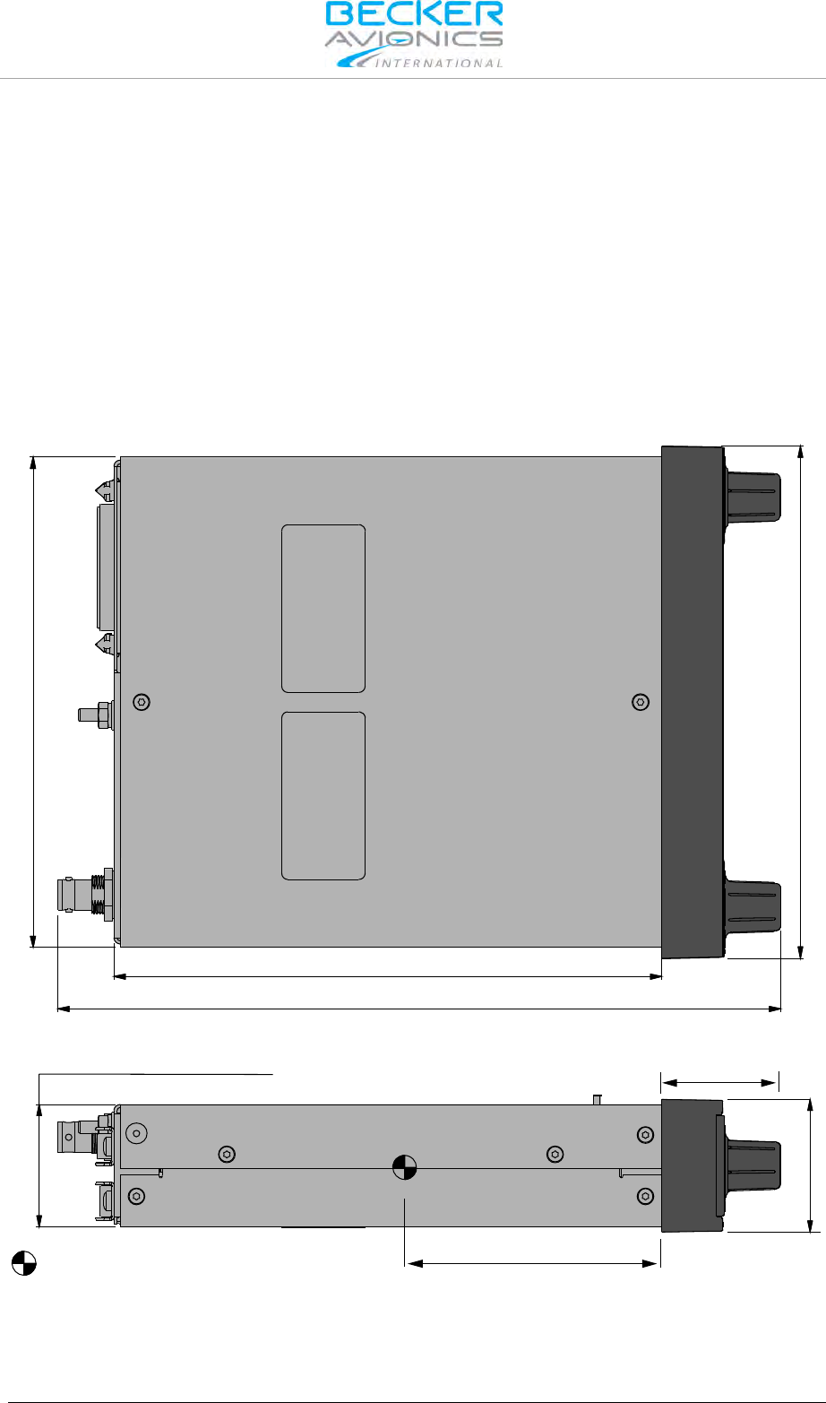
Installation
Mechanical Installation
DV14307.03 Issue 04 March 2016 Transceiver Family 620X 39
2.4.2. AR6203 Installation
Install AR6203 in the aircraft instrument panel within easy view and reach of pilot/operator. The
location for AR6203 installation shall be at least 30 cm away from the aircraft magnetic compass, to
avoid any interference to the magnetic compass caused by the transceiver. Leave a clearance of
minimum 5 mm between the AR6203 and other avionics to allow air circulation. Forced cooling is
usually not required.
For installation of the AR6203 use the designated mounting kit MK6403-1.
• Secure the mounting tray in the aircraft by using the 6 holes located on both sides of the
frame, marked in the Figure with letter "C". Countersunk screws are included in the
MK6403-1 kit.
• Slide AR6203 into the mounting tray all the way in, thereafter use an Allen wrench (3/32")
to tightening the unit to its final position.
Dimensions mm (inch)
CENTER OF GRAVITY
152±0.3 (5.984 in ±0.011)
38±0.3 (1.5 in ±0.012) 36.7(1.453 in)
80 (3.149 in)
CG
158.8 (6.25 in)
41.2
(1.62 in)
170.1±0.8 (6.697 in ±0.031)
224.4±1.5 (8.83 in ±0.06)
Figure 2-6: AR6203 top view, side view

Installation
Mechanical Installation
40 Transceiver Family 620X DV14307.03 Issue 04 March 2016
Dimensions mm (inch)
Figure 2-7: Mounting kit MK6403-1 (for AR6203)
Dimensions MK6403
H
40.6 mm (1.598 in)
W
160.3 mm (6.311 in)
D
153.8 mm (6.055 in)
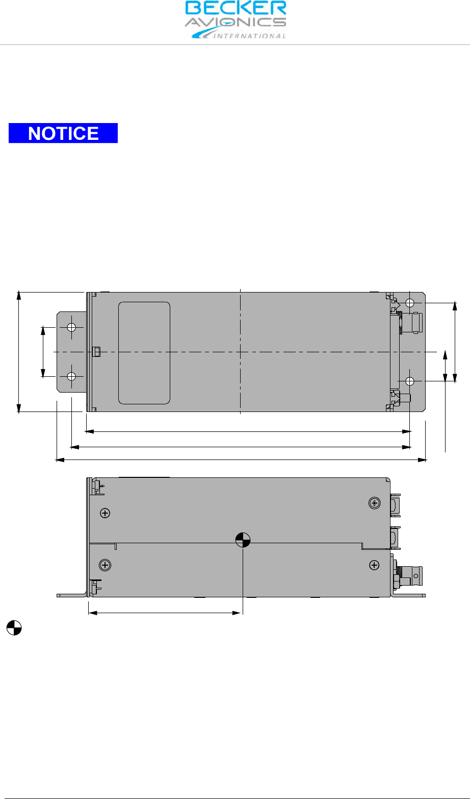
Installation
Mechanical Installation
DV14307.03 Issue 04 March 2016 Transceiver Family 620X 41
2.4.3. RT6201 Installation
Install the RT6201 at a suitable place in the aircraft for example directly on avionic bay or by using
mounting kit MK6201-(010).
To meet the conditions for certification use the mounting method with
mounting kit.
The mounting location for RT6201 shall be at least 30 cm away from the aircraft magnetic compass, to
avoid any interference to the magnetic compass by the transceiver. Leave a clearance of minimum
5 mm between the RT6201 and other avionics to allow air circulation. Forced cooling is usually not
required.
RT6201: Installation using RT6201 Mounting Holes
The required dimensions for installation using the mounting holes on the RT6201 are given in
Figure 2-11 (dedicated holes are marked with "X" letter).
Dimensions mm (inch)
CENTER OF GRAVITY
85 (3.346 in)
188±1 (7.4 in ±0.4)
172.5±1 (6.79 in ±0.4)
164.9±0.5 (6.49 in ±0.196)
15
(0.59 in) 40
(1.57 in)
61 (2.4 in)
25 (0.98 in)
Figure 2-8: RT6201 top view, side view
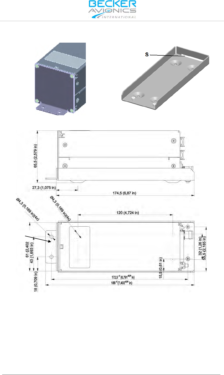
Installation
Mechanical Installation
42 Transceiver Family 620X DV14307.03 Issue 04 March 2016
Dimensions mm (inch)
Figure 2-9: RT6201 front view
Figure 2-10: MK6201-(010) mounting kit
Figure 2-11: RT6201 with mounting kit MK6201
X
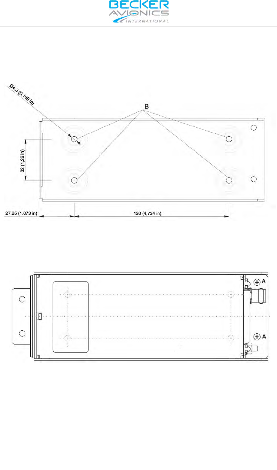
Installation
Mechanical Installation
DV14307.03 Issue 04 March 2016 Transceiver Family 620X 43
RT6201: Installation using Mounting Kit
The necessary dimensions for installation using the mounting kit MK6201-(010) are given in
Figure 2-12 (dedicated holes marked with "B" letter).
Dimensions mm (inch)
Figure 2-12: MK6201-(010) mounting slot fixing holes
First, secure the mounting kit frame in the aircraft, and then slide flat part "X" Figure 2-11 of the
RT6201 into the mounting slot S (Figure 2-10). Use two M3 screws to tighten the unit to the mounting
slot (details "A" shown on Figure 2-13).Suitable means are for example M3x6 DIN7985, associated flat
washer 3.2 DIN433 and spring washer 3.1 DIN127B.
Figure 2-13: RT6201 top view, fixed on mounting slot
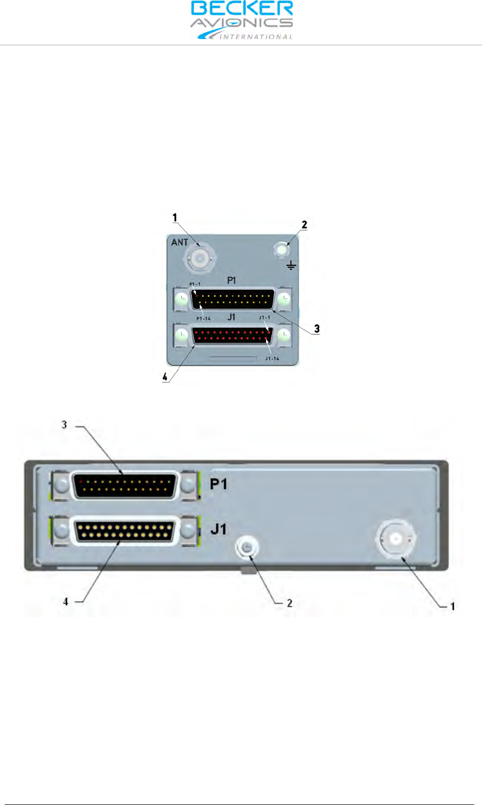
Installation
Electrical Interface
44 Transceiver Family 620X DV14307.03 Issue 04 March 2016
2.5. Electrical Interface
2.5.1. Connector and Pin Assignment (AR620X and RT6201)
Antenna Connector (Position 1)
The antenna connector (Figure 2-14, position 1) is a BNC type. The antenna port designed for
operating with a nominal impedance of 50 Ω.
Grounding Bolt (Position 2)
The transceiver has a M4 threaded grounding bolt (Figure 2-14,position 2) allowing a low impedance
grounding of the unit, which is essential to avoid damage or malfunction in the case of indirect
lightning, EMI and HIRF conditions.
Figure 2-14: Rear plate AR6201 and RT6201, connectors P1 (male) and J1 (female)
Figure 2-15: Rear plate AR6203, connectors P1 (male) and J1 (female)

Installation
Electrical Interface
DV14307.03 Issue 04 March 2016 Transceiver Family 620X 45
P1 Connector (System Interfaces)
The P1 connector (Figure 2-14 and Figure 2-15, Position 3) is a DSUB male connector with 25 pins
and slide-in fastener.
Pin No.
Pin Name
Direction
Function
P1-1
SPK_HI
OUT
Speaker output signal (hot)
P1-2
HDPH1_A
OUT
Balanced output for headphone(s)1
P1-3
HDPH1_B
OUT
Balanced output for headphone(s)1
P1-4
AF_AUX_IN_HI
IN
Auxiliary audio input (hot)
P1-5
MIKE_DYN_HI
IN
Balanced input for dynamic microphone(s)
P1-6
MIKE_DYN_LO
IN
Balanced input for dynamic microphone(s)
P1-7
/IC
IN
Intercom key input;
ACTIVE state - closed contact to GND
P1-8
MIKE_STD_LO
-
Standard microphone(s) low (ground/return) used for
STD1, STD2 and STD3
P1-9
MIKE_STD2_HI
IN
Standard microphone 2 High (hot)
P1-10
ILL_LO
IN
Illumination low input
P1-11
P_SUPP
IN
Power supply Hot (positive)
P1-12
P_SUPP
IN
Power supply Hot (positive)
P1-13
P_SUPP_GND
-
Power supply ground (return)
P1-14
SPK_LO
-
Speaker ground (return)
P1-15
LINE_OUT
OUT
Linear audio output, unbalanced
P1-16
AGC_OUT
OUT
Receiver AGC output
P1-17
/PTT1
IN
Press To Talk key input1
ACTIVE state - closed contact to GND
P1-18
MIKE_STD1_HI
IN
Standard Microphone 1 High (hot)
P1-19
MIKE_STD3_HI
IN
Standard Microphone 3 High (hot)
P1-20
HDPH2_A
OUT
Balanced Output for headphone(s)2
P1-21
AF_AUX_IN_LO
IN
Auxiliary audio input low (return)
P1-22
HDPH2_B
OUT
Balanced output for headphone(s)2
P1-23
ILL_HI
IN
Illumination high
/PWR_EVAL
OUT
Power on monitor output
P1-25
P_SUPP_GND
-
Power supply ground (return)

Installation
Electrical Interface
46 Transceiver Family 620X DV14307.03 Issue 04 March 2016
J1 Connector (Serial Interfaces and Discrete I/O’s)
The J1 connector is a D_SUB female connector with 25 sockets and slide-in fastener.
Pin No.
Pin Name
Direction
Function
J1-1
CPIN
-
Reserved coding pin
J1-2
TX2+
OUT
Auxiliary control interface
J1-3
RX2+
IN
Auxiliary Control Interface
J1-4
/SQL_EVAL
OUT
Squelch monitor output
ACTIVE state - closed contact to GND
J1-5
/PTT2
IN
Press-To-Talk key input 2
ACTIVE state - closed contact to GND
J1-6
SHIELD_1
-
Secondary control & service interface SHIELD
J1-7
TX1+
OUT
Secondary control & service interface
J1-8
RX1+
IN
Secondary control & service interface
J1-9
TX2-
OUT
Auxiliary control interface
J1-10
RX2-
IN
Auxiliary control interface
J1-11
SHIELD_2
-
Auxiliary control interface SHIELD
J1-12
/EXT_SO
IN
External "Exchange" key
Falling edge will activate frequency exchange
J1-13
/SRV_EN
IN
Service enable pin
ACTIVE state - closed contact to GND
J1-14
TX1-
OUT
Secondary control & service interface
J1-15
RX1-
IN
Secondary control & service interface
J1-16
NC
not connected
J1-17
/SQL_SW
IN
"Squelch Force-OFF" input
ACTIVE state - closed contact to GND
J1-18
NC
not connected
J1-19
NC
not connected
J1-20
/ISOL
IN
"ISOL" input
ACTIVE state - closed contact to GND
J1-21
D_GND
-
Discrete lines ground
J1-22
D_GND
-
Discrete lines ground
J1-23
D_GND
-
Discrete lines ground
J1-24
/MIKE_SW
IN
Configuration selector CFG1 and CFG2
J1-25
/EXT_ON
IN
External Power ON input
ACTIVE state - closed contact to GND

Installation
Electrical Interface
DV14307.03 Issue 04 March 2016 Transceiver Family 620X 47
2.5.1.1. Inputs / Outputs
Microphone Connection – Standard Microphones
Pin No.
Pin Name
Direction
Function
P1-8
MIKE_STD_LO
-
Standard microphone(s) low (ground/return)
used for STD1, STD2 and STD3
P1-9
MIKE_STD2_HI
IN
Standard microphone 2 high (hot)
P1-18
MIKE_STD1_HI
IN
Standard microphone 1 high (hot)
P1-19
MIKE_STD3_HI
IN
Standard microphone 3 high (hot)
The transceiver has three unbalanced inputs STD1, STD2 and STD3. Each input has an input
impedance of 110 Ω and a nominal sensitivity of 110 mV.
This sensitivity level is adjustable in the configuration setup from 9...1500 mV independently for each
of the microphones. The power supply delivered from pins P1-9, P1-18 and P1-19 for supply of the
connected microphone(s) is > 8 V DC (8.3 V nominal) open circuit with an output impedance of 120 Ω.
Note:
• Sensitivity range 25...1000 mV was qualified under environmental conditions.
• The AR/RT620X transceiver family provides power supply to support two microphones in
parallel on each of the three standard microphone inputs. Combining only microphones of
the same type / impedance is always highly recommended.
• In installations where high interferences were detected, we recommend the use of
sensitivity levels between 27...1500 mV.
• We also recommend mounting the jacks generally isolated from aircraft frame in order to
avoid ground loops.
Microphone Connection - Dynamic Microphone
Pin No.
Pin Name
Direction
Function
P1-5
MIKE_DYN_HI
IN
Balanced input for dynamic microphone(s)
P1-6
MIKE_DYN_LO
IN
Balanced input for dynamic microphone(s)
Interfacing with dynamic microphones, the transceiver provides balanced inputs with an impedance of
140 Ω and a nominal sensitivity of 1.6 mV. This sensitivity level is adjustable in the configuration setup
from 1...20 mV. Two dynamic microphones in parallel may be connected (identical technical
characteristics of the microphones are preferable).
Note:
• The sensitivity range of 1...20 mV was qualified under environmental conditions. In
installations where high interferences are detected we recommend the use of sensitivity
levels between 2...20 mV.
• We also recommend mounting the jacks generally isolated from aircraft frame in order to
avoid ground loops.
Speaker Connection
Pin No.
Pin Name
Direction
Function
P1-1
SPK_HI
OUT
Speaker output signal
P1-14
SPK_LO
-
Speaker ground (return)
The speaker output provides nominal 4 W into 4 Ω.
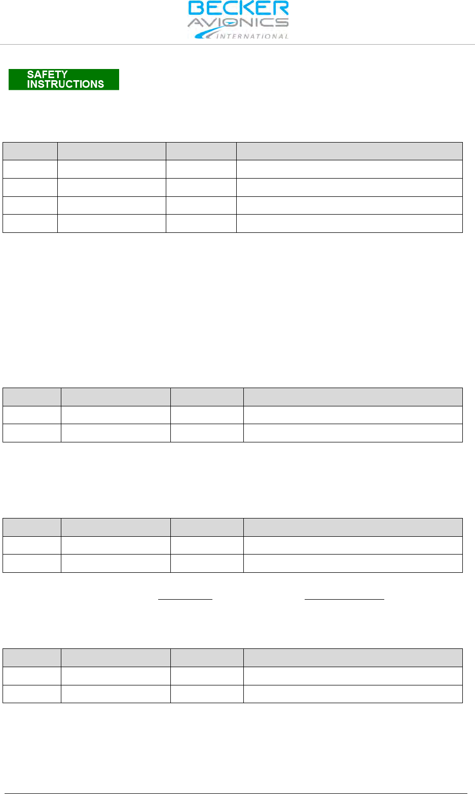
Installation
Electrical Interface
48 Transceiver Family 620X DV14307.03 Issue 04 March 2016
The magnetic field of a speaker influences the magnetic compass. When
choosing the mounting point, a safe distance between the compass and
the speaker must be determined. After speaker installation, verify the
accuracy of the magnetic compass.
Headphone(s) Connection
Pin No.
Pin Name
Direction
Function
P1-2
HDPH1_A
OUT
Balanced output for headphone(s) 1
P1-3
HDPH1_B
OUT
Balanced output for headphone(s) 1
P1-20
HDPH2_A
OUT
Balanced output for headphone(s) 2
P1-22
HDPH2_B
OUT
Balanced output for headphone(s) 2
The headphone 1 output is a balanced, transformer-coupled output providing nominal 300 mW into
75 Ω. Using a shielded single wire for headphones requires an unbalanced output configuration. To
achieve this, ground P1-3 (connect pin P1-13 with P1-25).
The headphone 2 output is a balanced output providing nominal 200 mW into 75 Ω.
Up to two headphones with phone-impedance of 300 Ω (or higher) may be connected in parallel on
each circuit, therefore up to four headphones can be connected at the same time.
Note: It is highly recommended to mount the jacks isolated from aircraft frame in
order to avoid ground loops.
CAUTION: The headphone 2 output shall be always floating (cannot be connected in
unbalance configuration as headphone 1).
Panel Illumination
Pin No.
Pin Name
Direction
Function
P1-10
ILL_LO
IN
Illumination low input
P1-23
ILL_HI
IN
Illumination high input
The VHF transceiver provides illumination for pushbuttons and LCD display. Configuration of panel
illumination provides the configuration setup accessible via front panel. Depending on setup selection,
14 or 28 V fixed illumination voltage, or aircraft dim-bus voltage is in operation.
Connect ILL_LO (pin P1-10) to aircraft ground. Connect ILL_HI (pin P1-23) to dimming bus.
"Auxiliary" Audio Input
Pin No.
Pin Name
Direction
Function
P1-4
AF_AUX_IN_HI
IN
Auxiliary audio input hot
P1-21
AF_AUX_IN_LO
-
Auxiliary audio input low return
The AF auxiliary input enables to connect an external audio source (NAV, music-player, etc.) to the
transceiver. The external audio is audible only when transceiver is in receiving mode.
Input sensitivity is adjustable in the configuration setup from 50 mV...8 V. The impedance of this input
is 600 Ω.
"LINE_OUT" Audio Output
Pin No.
Pin Name
Direction
Function
P1-14
SPK_LO
-
Speaker ground (return)
P1-15
LINE_OUT_HI
OUT
Linear audio output, unbalanced
The LINE OUT enables to connect e.g. an external voice recorder to the transceiver when used in
ground-based installations. The LINE OUT output provides nominal 1 VRMS into 1000 Ω.

Installation
Electrical Interface
DV14307.03 Issue 04 March 2016 Transceiver Family 620X 49
External Power ON
Pin No.
Pin Name
Direction
Function
J1-25 /EXT_ON IN
External Power ON input
ACTIVE state - closed contact to GND
External Power ON input provides possibility to power "ON" the system by connecting this pin to
ground.
Push-To-Talk (/PTT)
Pin No.
Pin Name
Direction
Function
P1-17 /PTT1 IN
Push-To-Talk key input 1
ACTIVE state - closed contact to GND
J1-5 /PTT2 IN
Push-To-Talk key input 2
ACTIVE state - closed contact to GND
There are two Push-to-Talk inputs available /PTT1 and /PTT2, e.g. one for the pilot and the other for
the co-pilot.
Each input has an internal pull up. While the input is connected to ground a current of less than 1 mA
will flow. The transceiver enters transmit operation, if either one or both inputs are connected to
ground.
According to microphone(s) configuration, signal from particular inputs can or cannot modulate
transmissions.
External Intercom Key (IC)
Pin No.
Pin Name
Direction
Function
P1-7 IC IN
Intercom key input;
ACTIVE state - closed contact to GND
With pin 7 connected to ground the transceiver provides intercom operation. This input has an internal
pull up and is LO active. For installations where automatic intercom operation activates via VOX, a
connection of pin 7 is not necessary. While connected to ground, a current of max. 1 mA will flow.
This discrete input activates the intercom:
• When VOX does not work satisfactorily because of extreme loud cockpit environment
caused e.g. by ambient noise.
• When speaker is enabled in current audio in/out configuration (configuration setup)
Isolation Mode (/ISOL)
Pin No.
Pin Name
Direction
Function
J1-20 /ISOL IN
ISOL input for separation from co-pilot
(passenger)
ACTIVE state - closed contact to GND
AR620X transceiver provides two microphone paths. Each microphone path allows connection of two
individual microphones. Depending on configuration, it is possible to connect pilot and co-pilot
microphones on one path and two passenger microphones on the second.
When /ISOL is active (isolation mode) passengers are isolated from pilots intercom as well as from the
radio transmission, but still can freely communicate with each other.
When /ISOL is inactive both the pilots and the passengers connected to one common intercom circuit.
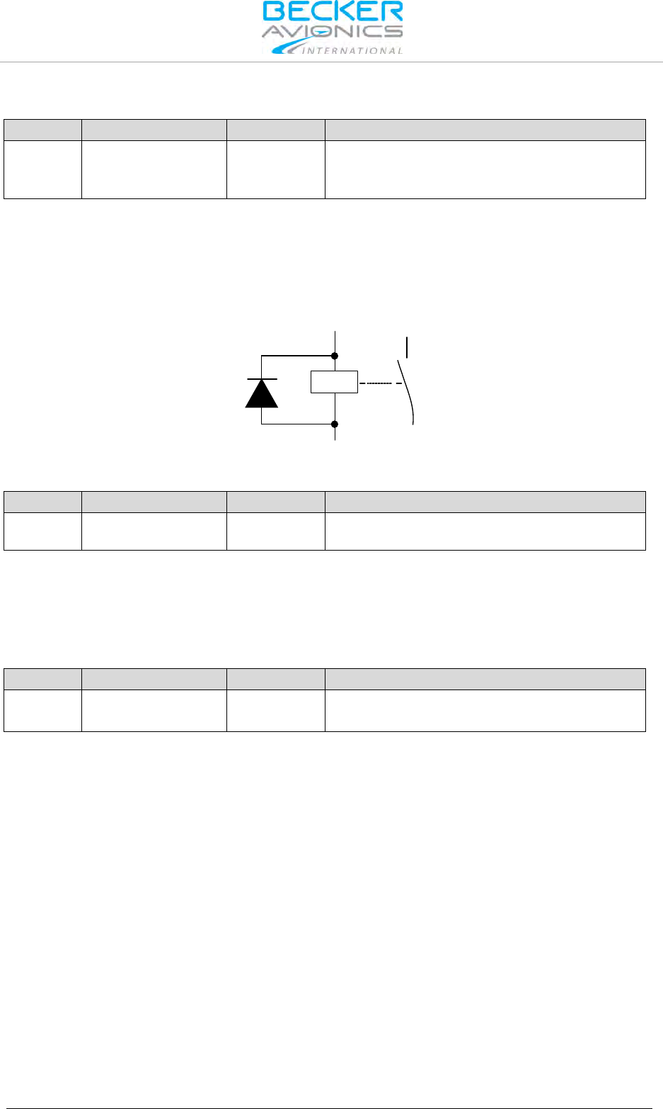
Installation
Electrical Interface
50 Transceiver Family 620X DV14307.03 Issue 04 March 2016
Power Indication (/PWR_EVAL)
Pin No.
Pin Name
Direction
Function
P1-24 /PWR_EVAL OUT
Power on Monitor output:
AR6201 "OFF" - open circuit AR6201 on - closed
circuit to GND (max. 100 mA)
This output indicates whether the transceiver is in "ON" or "OFF" status by means of an open collector
function. The output internally connects to ground when the unit is "ON" and allow a current of
maximum 100 mA to drive an external relay for example. The output shows high impedance when the
transceiver is "OFF".
Note: In order to avoid damage of this output a protection diode in parallel to the
external relay shall connected.
Rel1
+Supply
/PWR_EVAL
VHF Channel Signal Indication (/SQL_EVAL)
Pin No.
Pin Name
Direction
Function
J1-4 /SQL_EVAL OUT
Indicates presence of the VHF channel’s signal
on the audio outputs.
This output indicates presence of the VHF channel’s signal on the audio outputs. It is an open
collector output type. The output internally connects to ground when the unit receives signal on the
selected VHF channel and this audio signal is available on audio outputs. In this case a current of
maximum 100 mA can flow into the transceiver to drive an external relay for example. The output has
high impedance if the unit is switched off.
External Mike Switch (/MIKE_SW)
Pin No.
Pin Name
Direction
Function
J1-24 /MIKE_SW IN
Configuration selector CFG1 and CFG2.
ACTIVE state - closed contact to GND
The external Mike switch provides selection between the two available audio in/out configurations:
CFG1 and CFG2. Configurations can also be changed during flight in configuration setup.
• When /MIKE_SW is active then configuration CFG1 is in use.
• When /MIKE_SW is inactive then CFG2 is in use.
Each configuration CFG1 and CFG2 stores several parameters that can be set in configuration setup
pages. (For details, refer to chapter 2.8).
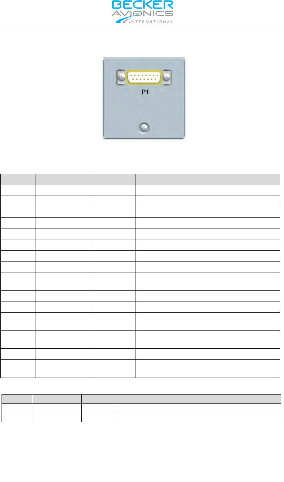
Installation
Electrical Interface
DV14307.03 Issue 04 March 2016 Transceiver Family 620X 51
2.5.2. Connector and Pin Assignment (RCU6201)
Figure 2-16: Connector on rear plate of RCU6201
P1 Connector (System Interface)
The P1 connector (Figure 2-16) is a DSUB male connector with 15 pins and slide-in fastener.
Pin No.
Pin Name
Direction
Function
P1-1
TX0_422+
OUT
Primary Control & Service Interface
P1-2
TX0_422-
OUT
Primary Control & Service Interface
P1-3
RX1_422+
IN
Auxiliary Control Interface
P1-4
RX0_422+
IN
Primary Control & Service Interface
P1-5
RX0_422-
IN
Primary Control & Service Interface
P1-6
ILL_LO
IN
Illumination low input
P1-7
TX1_422-
OUT
Auxiliary Control Interface
P1-8
ILL_HI
IN
Illumination high
P1-9 GND -
Power supply Ground (return), shielding for
RS422, Ground for discrete lines
P1-10
RX1_422-
IN
Auxiliary Control Interface
P1-11
SUPP_IN
-
Power supply Hot (positive)
P1-12 /SRV_EN OUT
Service enable pin
ACTIVE state - closed contact to GND
P1-13 /EXT_ON IN
External Power ON input
ACTIVE state - closed contact to GND
P1-14
TX1_422+
OUT
Auxiliary Control Interface
P1-15 /EXCH_CH IN
External "Exchange" key
ACTIVE state - closed contact to GND
Panel Illumination
Pin No.
Pin Name
Direction
Function
P1-6
ILL_LO
IN
Illumination low input
P1-8
ILL_HI
IN
Illumination high input
The RCU6201 controller push-buttons and LCD display can be illuminated. The illumination can be
configured in the configuration setup via front panel or externally via pin P1-6/P1-8 For external
configuration connect pin P1-6 to system ground and pin P1-8 to dimming voltage bus.

Installation
Installation and Configuration
52 Transceiver Family 620X DV14307.03 Issue 04 March 2016
External Power ON (/EXT_ON)
Pin No.
Pin Name
Direction
Function
P1-13 /EXT_ON IN/OUT
External Power ON input/output
ACTIVE state - closed contact to GND
The External Power "ON" input provides the possibility to power on the system by ensuring this pin is
earthed. This can be connected in installations with a central avionics power switch or to power on
RT6201.
External Exchange (/EXCH_CH)
Pin No.
Pin Name
Direction
Function
P1-15 /EXCH_CH IN
External "Exchange" key
ACTIVE state - closed contact to GND
The External "Exchange" input provides possibility to change active and preset frequency or activate
SCAN mode by means of momentary switch.
2.6. Installation and Configuration
Connection to the following equipment is required as minimum for 620X transceivers:
• Power supply
• Antenna
• Microphone (direct or via external audio panel)
• Headphone or speaker (direct or via external audio panel)
• Push-To-Talk (PTT) switch
Use only cables which are qualified for aircraft use (self-extinguishing).
Use AWG 20 for power supply and AWG 22/24 for other cables.
Fit sleeves over the solder joints on the equipment connector. Crimp
connectors are also available from Becker.
Protect the power supply with a 7.5 A fuse.
The VHF transceiver is protected internally by a 5 A fuse.
• Type-specific cable harnesses are also available for the aircraft wiring (contact Becker
Avionics for detailed information).
• No RF antenna cables or HF cables should be included in the cable harnesses of the
system. Avoid routing of the cable loom along with other wiring, which carry audio power
or pulses.
• Check the wiring carefully before powering up the unit and check particularly that power
supply lines are not interchanging.

Installation
Antenna Installation
DV14307.03 Issue 04 March 2016 Transceiver Family 620X 53
Installation of 620X transceivers requires correct wiring and configuration. All necessary information
for common installations shows chapter "Installation", page 33, including wiring diagrams and
recommended configurations.
Aircraft Type
Chapter Reference
Single Seat Glider
2.10.1, page 70
Twin Seat Motor Glider
2.10.2, page 73
General Aviation (GA) Aircraft
2.10.3, page 75
Individual Dual Headset Configuration (two IC Circuit)
2.10.4, page 77
Twin Seat with AR620X Tandem Configuration
2.10.5, page 79
Aircraft with four Seats (no TANDEM)
2.10.6, page 81
Installation with RT6201 and RCU6201
2.10.7, page 83
Aircraft with Intercom System
2.10.8, page 84
Twin Seat with RT6201 Tandem Configuration
2.10.9, page 87
2.7. Antenna Installation
The transceiver requires a standard 50 Ω vertically polarized VHF antenna. Follow manufacturer's
instructions for antenna installation. In addition, consider the following recommendations:
• The COM antenna shall be on an electrical conductive surface or, on a ground plane with
sufficient area of approximately 60 x 60 cm installed. (VSWR ≤ 3:1)
• Separate the COM antenna from any installed GPS antennas by at least 50 cm and as far
away from any ELT antenna.
Note: Some ELTs have exhibited re-radiation problems generating harmonics that may cause
interference with other receivers like GPS. This can happen when the transceiver or other COMM
devices are transmitting on certain frequencies such as 121.5 MHz or 121.175 MHz, which may
cause the ELT output circuit to auto-oscillate.
2.8. Configuration Setup
The configuration setup enables the avionics technician to set up the equipment configuration on
ground.
We do not recommend performing changes on the configuration setup in-flight.
In most cases, entering configuration setup will be from the primary controller to access controller and
transceiver parameters. If installed, the second controller (RCU6201) should be switched off.
Configuration setup on RCU6201 gives access to parameters of second controller. RCU6201
configuration setup shall be used only if different settings for "BRIGHTENSS" or "ILLUMINATION
CURVE" are required.
Note:
• For single block AR620X, primary controller is this one directly connected to transceiver,
for remote RT6201 transceiver primary controller is this one connected to primary control
interface.
• After power on the second controller (RCU6201) parameters are synchronized with those
stored in primary controller. Any stored parameters in second controller (RCU6201) will be
overwritten!
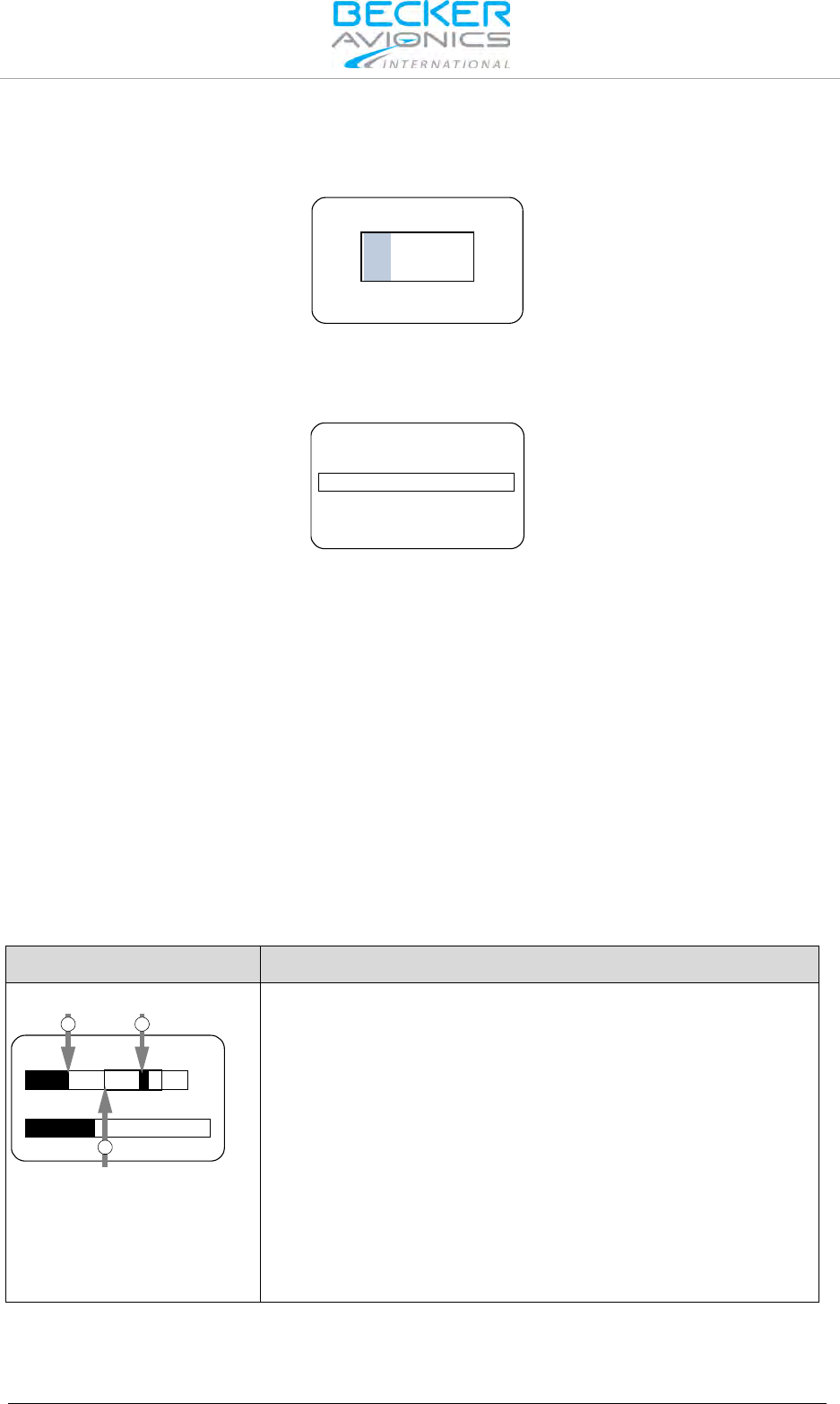
Installation
Configuration Setup
54 Transceiver Family 620X DV14307.03 Issue 04 March 2016
2.8.1. Start Configuration Setup
Hold down the "MDE" key during power up to access the configuration setup. The "PASSWORD
DIALOG" screen will appear.
6435
PASSWORD
Figure 2-17: "PASSWORD DIALOG"
Insert the 4-digit numerical code password "6435" by turning and pushing the "ROTARY ENCODER".
Confirm by pressing the "STO" key. Now the first page of configuration setup shows the "DEVICE
INFO" screen.
CM SW VER 2.06
CH SW VER 4.06
AR SN 03665
DEVICE INFO
Figure 2-18: "DECIVE INFO"
2.8.2. Navigate between Pages
The configuration setup consists of several pages. Navigation within main pages:
Page Down (next page): press "↕/SCN" or the "ROTARY ENCODER".
Page Up (previous page): press "IC/SQL" key.
For navigation within the sub-pages of the configuration setup, use the "ROTARY ENCODER".
2.8.3. Store Setup Data
The setting of any parameter is stored immediately after changing the parameter.
2.8.4. Leave Configuration Setup
Switch "OFF" the AR620X or RCU6201 to terminate the setup. All changes made up to this time will
be stored automatically. No special action is required before leaving setup page.
2.8.5. Adjust Volume Settings (VU Meter)
The VU Meter allows correct adjustment of audio input sensitivity. It is displayed on all sensitivity
setting menus.
Display Contents
Description
Example:
17 dB 3.5 mV
VU
DYN MIKE SENS
1 2
3
1: Current audio level
2: Hold max. level
3: Recommended range
(inside frame)
VU Meter, it is located in the middle below the menu name and
above the dedicated sensitivity setting bar.
It displays the current audio level value on selected audio input
("Current audio level") and holds the highest value of active audio
level recorded during last 3 seconds (displayed as "Hold max level"
bar).
Correct sensitivity is achieved if most of the time, while you are
speaking normally into the microphone, the "Hold max level" bar
remains in the "Recommended range".
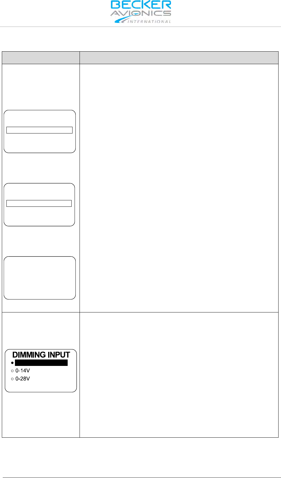
Installation
Configuration Setup
DV14307.03 Issue 04 March 2016 Transceiver Family 620X 55
2.8.6. Configuration Setup Pages - Description
Display Contents
Description
"DEVICE INFO":
After entering the "Configuration Setup" the first page "DEVICE INFO" is
displayed. This page shows information about the SW version and the
serial number of the transceiver.
AR620X
CM SW VER 2.06
CH SW VER 4.06
AR SN 03665
DEVICE INFO
For AR620X "DEVICE INFO" displays information about;
• Transceiver SW version (CM SW VER).
• Controller SW version (CH SW VER).
• AR620X serial number (AR SN).
RCU6201 as primary
controller of RT6201
CM SW VER 2.06
CH SW VER 4.06
CM SN 00005
CH SN 00005
DEVICE INFO
For RCU6201 connected as primary controller of an RT6201, this
page displays information about;
• Transceiver SW version.
• Controller SW versions (CH SW VER).
• RT6201 serial number (CM SN).
• RCU6201 serial number (CH SN).
RCU6201 as secondary
controller
CH SW VER 4.06
CH SN 00005
DEVICE INFO
For RCU6201 connected as secondary controller this page
displays information about;
• Controller SW version (CH SW VER).
• RCU6201 serial number (CH SN).
"DIMMING INPUT":
One of three options can be selected by turning the "ROTARY
ENCODER" to dim illumination for the display and push-button. Finalize
the selection by pressing "STO" push-button.
NONE
NONE:
The illumination for LCD and push-buttons is controlled via the
"ROTARY ENCODER" on the transceiver itself. The pilot can adjust the
brightness in the user menu.
0…14 V or 0…28 V:
The background lighting for LCD and push-buttons is controlled (via pin
P1-10/P1-23) by the dimming bus of the aircraft. The dimming curve is
adjustable within the range from 0…14 VDC respectively 0…28 VDC.
Adjusting the brightness via the "ROTARY ENCODER" is no longer
possible after selecting this option.
Note: Menu available on primary and secondary controller.
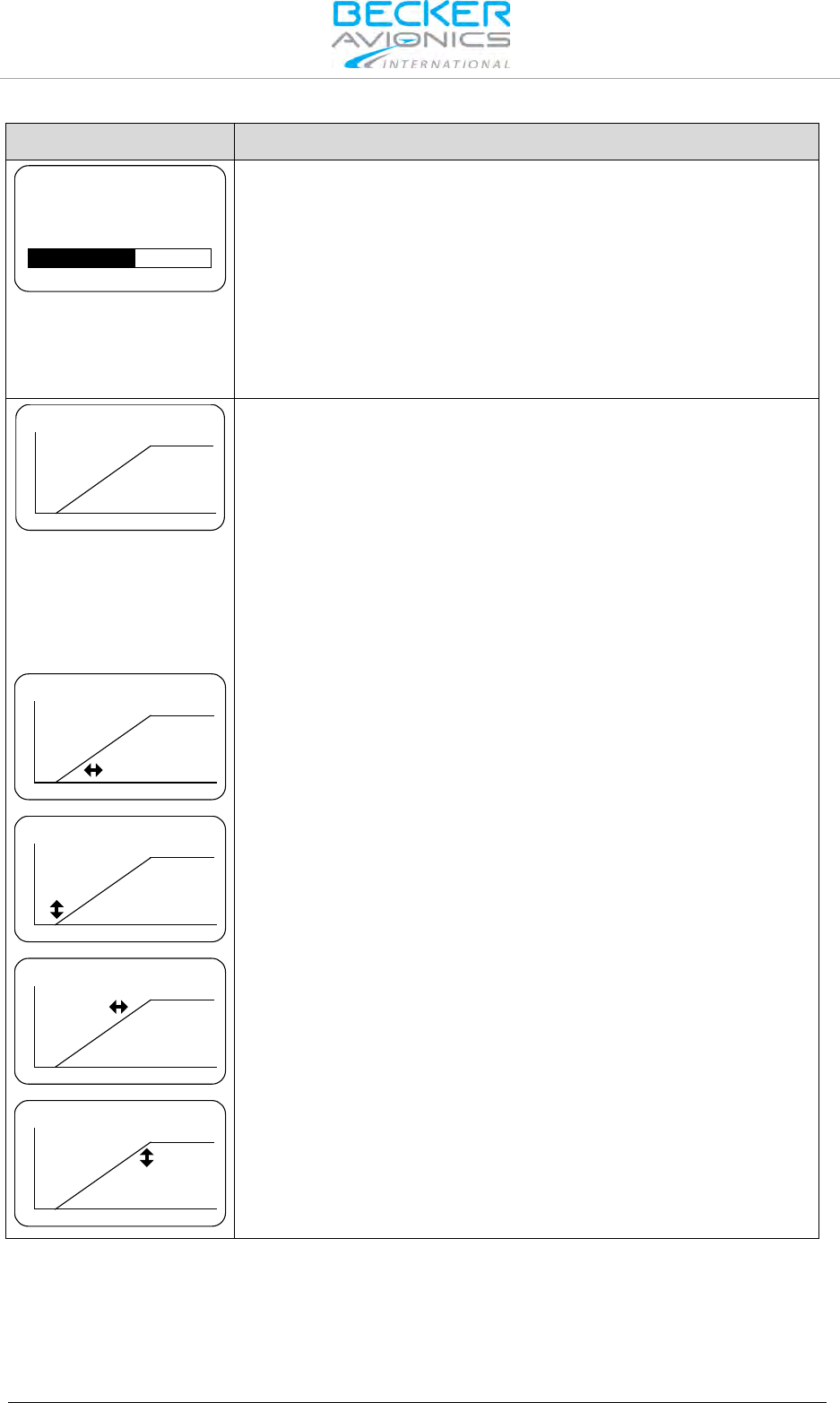
Installation
Configuration Setup
56 Transceiver Family 620X DV14307.03 Issue 04 March 2016
Display Contents
Description
65
BRIGHTNESS
"BRIGHTNESS":
The brightness of the LCD and push-button illumination can be adjusted
between 0% (off) and 100%. Select your brightness by turning
"ROTARY ENCODER". The BRIGHTNESS settings can also be
adjusted in the user menu. Pilots can change the parameter at any time.
BRIGHTNESS settings are separate for each controller therefore this
menu is available on both controllers.
Note: This page is displayed only if dimming input is set to
"NONE". Otherwise the aircraft dimming bus will control the
brightness
14V
I
L
L
U
M
ILLUM CURVE
"ILLUM CURVE":
The page "ILLUM CURVE" is displayed only if the DIMMING input is
either selected for "14 V or 28 V" dim-bus voltage. The illumination
curve shows the relation between dimming bus voltage and brightness
of the LCD and push-button illumination.
Two adjustable points V1 and V2 define the illumination curve.
Select the respective parameter by pushing the "STO" button and then
adjust the value in horizontal (left/right) respectively vertical (up/down)
direction using the "ROTARY ENCODER".
Note: Menu available on primary and secondary controller.
14V
I
L
L
U
M
ILLUM CURVE
(1) This parameter defines the horizontal parameter V1x (minimum
values: 1.5 V for 14 V dimming bus and 4 V for 28 V dimming bus). Up
to this value the brightness is zero. When reaching V1x the brightness is
immediately adjusted to V1y.
14V
I
L
L
U
M
ILLUM CURVE
(2) This parameter defines the vertical parameter V1y which is the level
of brightness that is set when trigger point V1x is reached.
14V
I
L
L
U
M
ILLUM CURVE
(3) This parameter defines the horizontal parameter V2x (maximum
values: 14 V or 28 V depending on selected dimming input) where the
illumination curve reaches the maximum brightness level.
14V
I
L
L
U
M
ILLUM CURVE
(4) This parameter defines the vertical parameter V2y which is the
maximum brightness.
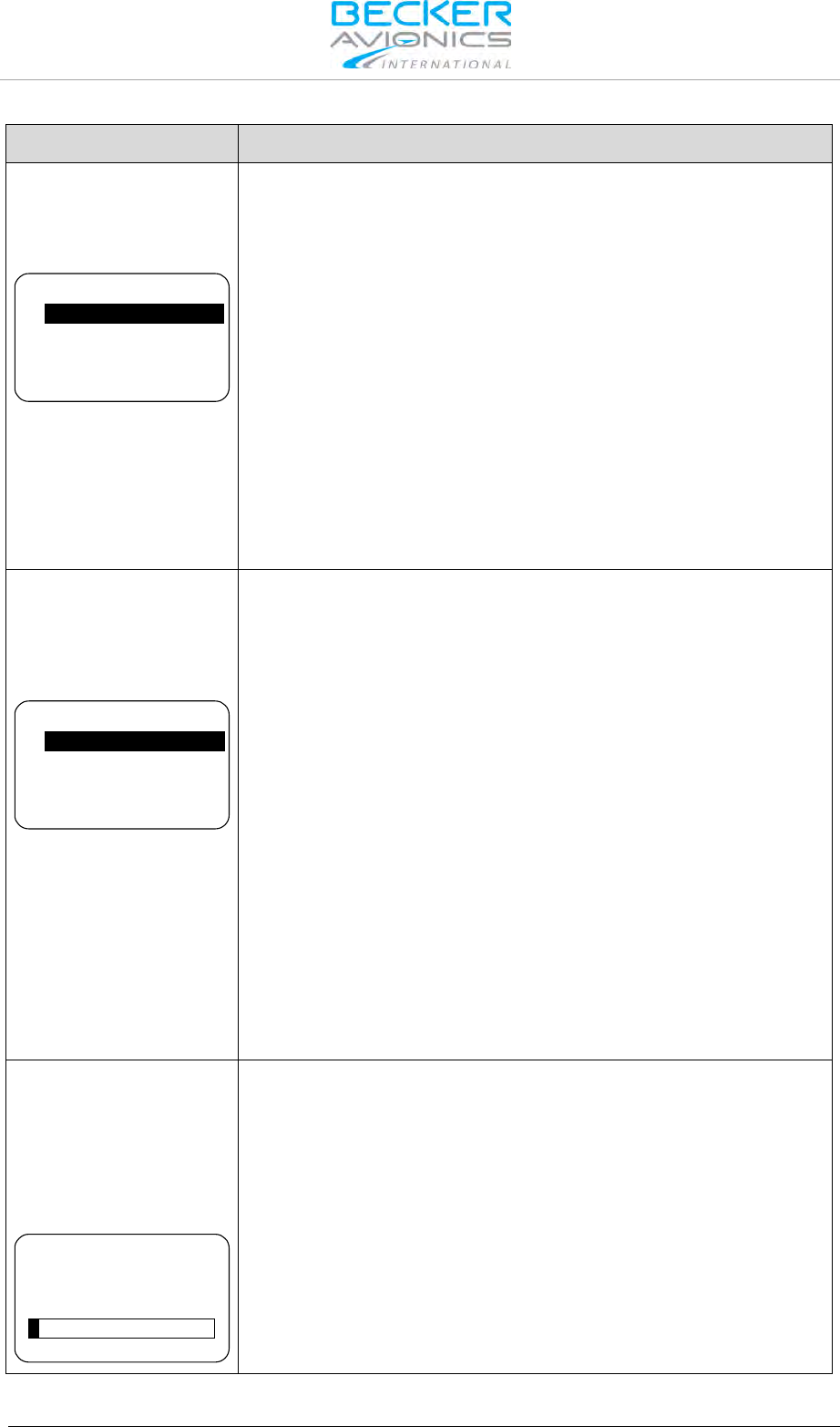
Installation
Configuration Setup
DV14307.03 Issue 04 March 2016 Transceiver Family 620X 57
Display Contents
Description
"MEM OPTIONS":
Two options can be selected on "MEMORY OPTIONS" page. By means
of the "ROTARY ENCODER" one option can be highlighted and
enabled/ disabled by pushing the "STO" button.
CHANNEL STORE
STORE LAST CHANNELS
MEM OPTIONS
CHANNEL STORE:
If this option is enabled frequencies can be stored in any of the 99
available channels.
Even if the "CHANNEL STORE" option is disabled the user has access
to previously stored "User Channels"
STORE LAST CHANNEL
If this option is enabled, the device automatically stores the last used
VHF frequency in "Last Channel" database and user has a read access
to this database.
If this option is disabled the stored data in the "LAST CHANNEL"
database is not accessible.
Note: Menu available on primary and secondary controller.
"MDE PAGES":
On "MDE PAGES" page three options are selectable by means of the
"ROTARY ENCODER". The three frequency selection modes provide
different user interfaces for operating frequency selection.
Enabling/Disabling can be toggled by pushing the "STO" button.
STANDBY FREQUENCY
BATTERY VOLTAGE
CHANNEL MEMORY
MDE PAGES
STANDBY FREQUENCY
Enables/disables "Standard Mode"
BATTERY VOLTAGE
Enables/disables "Direct Tune Mode".
CHANNEL MEMORY
Enables/disables "Channel Mode".
After deselecting "BATTERY VOLTAGE" the "DIRECT TUNE MODE"
page is no longer available in the normal operation.
Storing a frequency in a specific channel will be possible even if only
"BATTERY VOLTAGE" or "STANDBY FREQUENCY" remain selected.
At least one page will remain active, deselecting all options from the
"MDE PAGES" is not possible
Note: Menu available on primary and secondary controller.
"LOW BATT THR":
On "LOW BATT THR" page the threshold for indication of the
"LOW BATT" warning page can be adjusted (default setting is 10.5 V).
The low battery threshold depends on battery type in use and should be
adjusted within 10…33 V by the installer turning the "ROTARY
ENCODER". "LOW BATT" warning page is displayed if the supply
voltage drops below the "LOW BATT THR" value.
10.5
LOW BATT THR
Recommended vales:
"LOW BATT THR" = 11 V for 12 V battery
"LOW BATT THR" = 24 V for 24 V battery
Note: Menu available on primary and secondary controller.

Installation
Configuration Setup
58 Transceiver Family 620X DV14307.03 Issue 04 March 2016
Display Contents
Description
"CONFIGURATION":
On "CONFIGURATION" page 6 or 7 options can be selected. (refer to
the note under AUX AUTO MUTE in the column on the right side). Use
the "ROTARY ENCODER" to scroll up and down, then and push the
"STO" button for selection.
TANDEM
AUX INPUT
AUX AUTO MUTE
AUTO ISOL IN TX
CONFIGURATION
Options 1...4
AUTO ISOL IN TX
SCAN BEEP
FREQ CHANGE BEEP
SWAP MIKE IC
CONFIGURATION
Options 4...7
TANDEM
If selected, a second controller RCU6201 can be connected to
AR620X/RT6201.
AUX INPUT
If selected, the auxiliary audio signal applied to pins P1-4 / pin P1-21 is
audible on headphone / speaker.
Note: If the auxiliary audio input is not used, it is recommended to
deselect "AUX INPUT".
AUX AUTO MUTE
If selected the auxiliary audio input will be muted. The auxiliary audio
input is also muted if the receiver detects (based on squelch evaluation)
a signal.
When deselected the auxiliary audio input signal and the receiver signal
will intermix continuously.
Note: "AUX AUTO MUTE" is only displayed when "AUX INPUT" is
enabled.
AUTO ISOL IN TX
If selected a separation between the pilots and passenger intercom
circuits is provided while one of the pilots transmits.
SCAN BEEP
If selected the transceiver generates (only in scan function) a short beep
tone to notify a signal presence on the "PRESET FREQUENCY".
During signal reception on the "ACTIVE FREQUENCY" switch over to
the "PRESET FREQUENCY" is not possible. The audio remains on
"ACTIVE FREQUENCY" and a short beep tone is audible. Additionally
the "PRESET FREQUENCY" will appear contrast inverted in a
sequence of approximately one second.
FREQ CHANGE BEEP
If selected the transceiver generates a short beep on each change of
the "ACTIVE FREQUENCY".
SWAP MIKE IC
If selected the /IC input functions as /MIKE_SW input and /MIKE_SW
input operates as /IC input.
20 dB 800 mV
VU
AUX IN SENS
"AUX IN SENS":
On "AUX IN SENS" page the sensitivity adjustment of the auxiliary
audio input (Pin P1-4 / Pin P1-21), in the range 50...8000 mV, can be
set by turning the "ROTARY ENCODER".
This page is displayed only if ENABLE_AUX_IN is activated.
The VU meter shows the current signal level of the aux audio input and
always displays the highest detected signal value from the last
3 seconds.
Note: Menu available on primary controller.
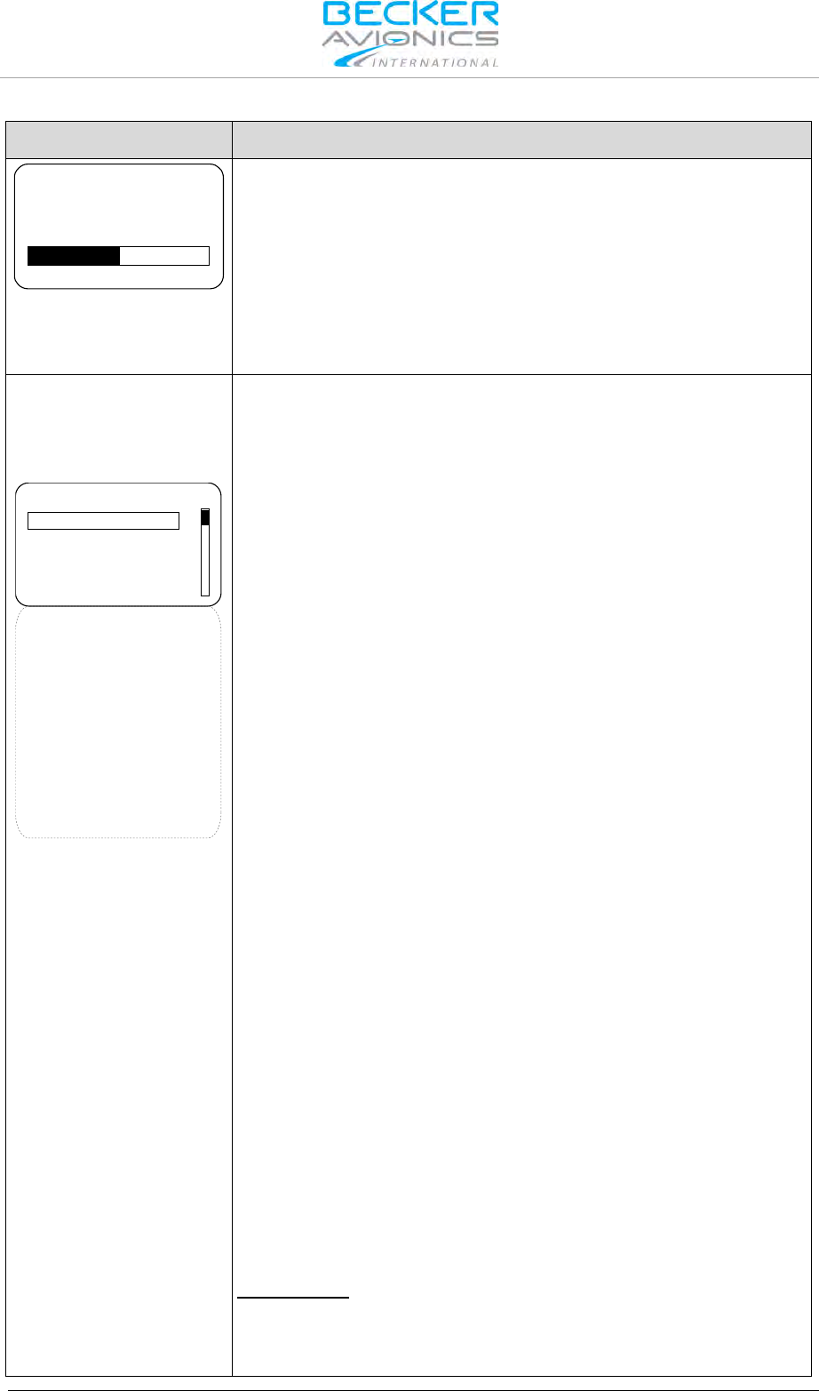
Installation
Configuration Setup
DV14307.03 Issue 04 March 2016 Transceiver Family 620X 59
Display Contents
Description
20
AUTO AUX ATT
"AUTO AUX ATT":
On "AUTO AUX ATT" page the attenuation for the auxiliary audio input
can be adjusted between 0...40 dB by turning the "ROTARY
ENCODER"
When intercommunication is initiated (regardless of the intercom
activation: "VOX", or "/IC" discrete input) the signal from auxiliary audio
input will be attenuated. After intercommunication is finished the
auxiliary audio will revert to its previous level.
Note: Menu available on primary controller.
"IN/OUT CFG 1":
On "IN/OUT CFG 1" page the microphone inputs and headphone
outputs for configuration CFG1 can be configured.
To scroll the page turn the "ROTARY ENCODER".
MICROPHONE 1
○ STD 1 MIKE
○ STD 2 MIKE
○ STD 3 MIKE
● DYN MIKE
○ NONE
MICROPHONE 2
○ STD 1 MIKE
○ STD 2 MIKE
○ STD 3 MIKE
○ DYN MIKE
● NONE
MIC ACTIVATION
BOTH MIKES
OUTPUTS
HEADPHONE 1
○ HEADPHONE 1
● SPEAKER
○ NONE
IN/OUT CFG 1
"MICROPHONE 1" (at one time only one option can be selected):
STD1 MIKE
Standard microphone input 1 (Pins P1-18/ P1-8) is selected.
STD2 MIKE
Standard microphone input 2 (Pins P1-9/ P1-8) is selected.
STD3 MIKE
Standard microphone input 3 (Pins P1-19/ P1-8) is selected.
DYN MIKE
Dynamic microphone input (Pins P1-6/ P1-5) is selected.
NONE
No microphone is used in microphone path 1.
"MICROPHONE 2" (at one time only one option can be selected):
STD1 MIKE
Standard microphone input 1 (Pins P1-18/ P1-8) is selected.
STD2 MIKE
Standard microphone input 2 (Pins P1-9/ P1-8) is selected.
STD3 MIKE
Standard microphone input 3 (Pins P1-19/ P1-8) is selected.
DYN MIKE
Dynamic microphone input (Pins P1-6/ P1-5) is selected.
NONE
No microphone is used in microphone path 2.
"MIC ACTIVATION"
BOTH MIKES ENABLED:
Input /PTT1 (Pin P1-17) activates transmission from microphone path 1
and 2.
Input /PTT2 (Pin J1-5) activates transmission from microphone path 2
and path 1.
Input /IC (Pin P1-7) activates intercom from microphone path 1 and 2.
BOTH MIKES DISABLED:
Input /PTT1 (Pin P1-17) activates transmission only from microphone
path 1
Input /PTT2 (Pin J1-5) activates transmission only from microphone

Installation
Configuration Setup
60 Transceiver Family 620X DV14307.03 Issue 04 March 2016
Display Contents
Description
path 2
Input /IC (Pin P1-7) activates intercom only from microphone path 1
"OUTPUTS"
HDPH 1 ENABLED
Audio available on headphone 1 output (Pins P1-2/P1-3)
HDPH 1 DISABLED
No audio available on headphone 1 output.
HDPH 2 ENABLED
Audio is available on headphone 2 output (Pins P1-20/P1-22), speaker
not available.
HDPH 2 DISABLED
No audio available on headphone 2 output, speaker not available.
SPEAKER ENABLED
Audio is available on speaker (Pins P1-1/P1-14), headphone 2 not
available
NONE
No audio on headphone 2 output or speaker output.
Note: Menu available on primary controller. Displayed only if
MIKE_SW input (Pin J1-24) has inactive state.
"IN/OUT CFG 2":
On "IN/OUT CFG 2" page the microphone inputs and headphone
outputs for configuration CFG2 can be configured. This page is
displayed only if MIKE_SW input (Pin J1-24) has active state. Please
note when MIKE_SW connected in installation both configurations for
IN/OUT CFG1 and IN/OUT CFG2 shall be configured.
To scroll the page turn the "ROTARY ENCODER".
MICROPHONE 1
○ STD 1 MIKE
○ STD 2 MIKE
○ STD 3 MIKE
● DYN MIKE
○ NONE
MICROPHONE 2
○ STD 1 MIKE
○ STD 2 MIKE
○ STD 3 MIKE
○ DYN MIKE
● NONE
MIC ACTIVATION
BOTH MIKES
OUTPUTS
HEADPHONE 1
○ HEADPHONE 1
● SPEAKER
○ NONE
IN/OUT CFG 2
"MICROPHONE 1" (at one time only one option can be selected):
STD1 MIKE
Standard microphone input 1 (Pins P1-18/ P1-8) is selected
STD2 MIKE
Standard microphone input 2 (Pins P1-9/ P1-8) is selected
STD3 MIKE
Standard microphone input 3 (Pins P1-19/ P1-8) is selected
DYN MIKE
Dynamic microphone input (Pins P1-6/ P1-5) is selected
NONE
No microphones is used in microphone path 1
"MICROPHONE 2" (at one time only one option can be selected):
STD1 MIKE
Standard microphone input 1 (Pins P1-18/ P1-8) is selected
STD2 MIKE
Standard microphone input 2 (Pins P1-9/ P1-8) is selected
STD3 MIKE
Standard microphone input 3 (Pins P1-19/ P1-8) is selected

Installation
Configuration Setup
DV14307.03 Issue 04 March 2016 Transceiver Family 620X 61
Display Contents
Description
DYN MIKE
Dynamic microphone input (Pins P1-6/ P1-5) is selected
NONE
No microphones is used in microphone path 2
"MIC ACTIVATION"
BOTH MIKES ENABLED:
Input /PTT1 (Pin P1-17) activates transmission from microphone path 1
and 2
Input /PTT2 (Pin J1-5) activates transmission from microphone path 2
and 1
Input /IC (Pin P1-7) activates intercom from microphone path 1 and 2
BOTH MIKES DISABLED:
Input /PTT1 (Pin P1-17) activates transmission only from microphone
path 1
Input /PTT2 (Pin J1-5) activates transmission only from microphone
path 2
Input /IC (Pin P1-7) activates intercom only from microphone path 1
"OUTPUTS"
HDPH 1 ENABLED
Audio available on headphone 1 output (Pins P1-2/P1-3)
HDPH 1 DISABLED
No audio is available on headphone 1 output.
HDPH 2 ENABLED
Audio is available on headphone 2 output (Pins P1-20/P1-22), speaker
not available.
HDPH 2 DISABLED
No audio available on headphone 2 output, speaker not available.
SPEAKER ENABLED
Audio is available on speaker (Pins P1-1/P1-14), headphone 2 not
available
NONE
No audio on headphone 2 output or speaker output.
Note: Menu available on primary controller.
Displayed only if MIKE_SW input (Pin J1-24) has inactive state.
Display Contents
Description
"STD1 MIKE SENS":
The sensitivity of standard microphone 1, "STD 1 MIKE SENS", input is
adjustable within the range 9...1500 mV by turning the "ROTARY
ENCODER".

Installation
Configuration Setup
62 Transceiver Family 620X DV14307.03 Issue 04 March 2016
Display Contents
Description
20 dB 150 mV
VU
STD1 MIKE SENS
Note: This page is only
displayed if :
Standard Mike 2 input is
selected in IN/OUT CFG1
and MIKE_SW input pin
status is [Inactive]
or
Standard Mike 2 input is
selected in IN/OUT CFG2
and MIKE_SW input pin
status is [Active].
The factory setting is 110 mV.
The VU meter displays the current signal level on the audio input and
also displays the highest signal value for the last 3 seconds.
When speaking normally into the microphone the bar graph should
remain within the recommended predefined range
Note: Adjust the microphone sensitivity by keeping the cockpit
noise suppression as high as possible, this will ensure correct
modulation.
If the sensitivity is adjusted to a smaller value (e.g. 10 mV) the cockpit
noises may become louder than for a higher adjustment (e.g. 100 mV).
Otherwise, adjusting the sensitivity to a very high value (e.g. 1000 mV),
the cockpit noise is very much reduced, but the modulation of the
transmitter might be not sufficient.
The installer shall perform a communication check after modification of
this parameter. Recommended is to perform this check with and without
a running engine.
Note: Menu available on primary controller.
For installations with high interferences it is recommended to use
sensitivity level 27...1500 mV.

Installation
Configuration Setup
DV14307.03 Issue 04 March 2016 Transceiver Family 620X 63
Display Contents
Description
"STD2 MIKE SENS":
The sensitivity of standard microphone 2 input can be adjusted in range
from 9...1500 mV by turning the "ROTARY ENCODER".
20 dB 150 mV
VU
STD2 MIKE SENS
Note: This page is only
displayed if :
Standard Mike 2 input is
selected in IN/OUT CFG1
and MIKE_SW input pin
status is [Inactive]
or
Standard Mike 2 input is
selected in IN/OUT CFG2
and MIKE_SW input pin
status is [Active].
The default setting is 110 mV.
VU meter displays current value of audio level from standard
microphone input 2 and displays the highest value of active audio level
recorded during last 3 seconds.
Correct sensitivity is achieved when you are speaking normally into the
microphone, this is confirmed by the "Hold max level bar" remaining in
"Recommended Range".
Note: The microphone sensitivity shall be adjusted to achieve a
correct modulation by keeping the cockpit noise suppression as
high as possible.
If the sensitivity value is very small (e.g. 10 mV) more cockpit noise will
be heard than if the sensitivity value is set to a higher level
(e.g. 100 mV).
Alternatively if the sensitivity value is very high (e.g. 1000 mV) the
cockpit noise will significantly be reduced but the modulation of the
transmitter may not be sufficient.
After modifying this parameter a communication check shall be done by
the installer. It is recommended to perform this communication check
with and without engine running.
Note: Menu available on primary controller.
For installations with high interference it is recommended to use
sensitivity level 27...1500 mV.
"STD3 MIKE SENS":
The sensitivity of standard microphone 3 Input can be adjusted in range
from 9...1500 mV by turning the "ROTARY ENCODER".
20 dB 150 mV
VU
STD3 MIKE SENS
Note:
This page is only displayed
if :
Standard Mike 3 input is
selected in IN/OUT CFG1
and MIKE_SW input pin
status is [Inactive]
or
Standard Mike 3 input is
selected in IN/OUT CFG2
and MIKE_SW input pin
status is [Active].
The default setting is 110 mV.
VU meter displays current value of audio level from standard
microphone input 3 and displays the highest value of active audio level
recorded during last 3 seconds.
Correct sensitivity is achieved when you are speaking normally into the
microphone, this is confirmed by the "Hold max level bar" remaining in
"Recommended Range".
Note: The microphone sensitivity shall be adjusted to achieve a
correct modulation by keeping the cockpit noise suppression as
high as possible.
If the sensitivity value is very small (e.g. 10 mV) more cockpit noise will
be heard than if the sensitivity value is set to a higher level
(e.g. 100 mV).
Alternatively if the sensitivity value is very high (e.g. 1000 mV) the
cockpit noise will significantly be reduced but the modulation of the
transmitter may not be sufficient.
After modifying this parameter a communication check shall be done by
the installer. It is recommended to perform this communication check
with and without engine running.
Note: Menu available on primary controller.
For installations with high interferences it is recommended to use
sensitivity level 27...1500 mV.
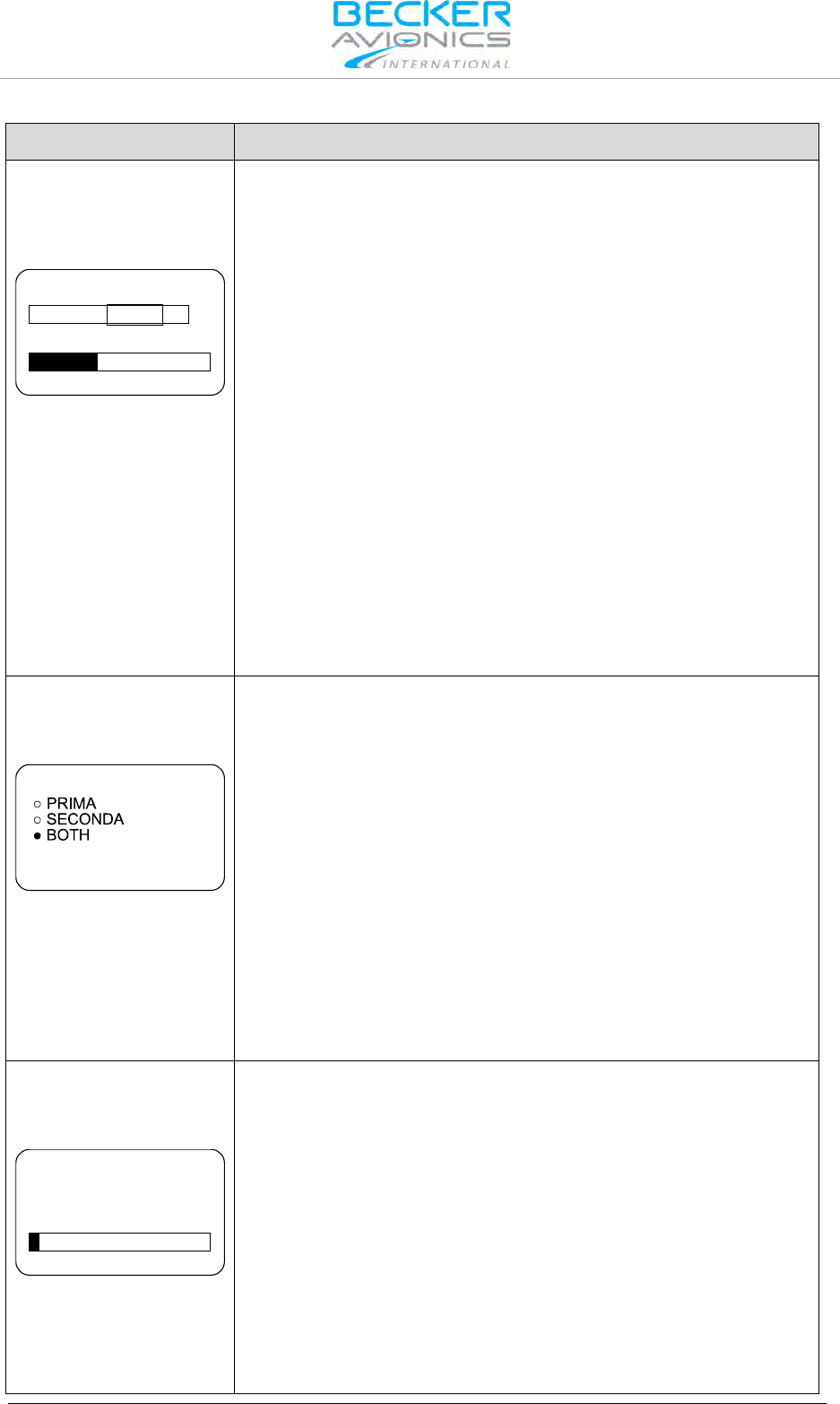
Installation
Configuration Setup
64 Transceiver Family 620X DV14307.03 Issue 04 March 2016
Display Contents
Description
"DYN MIKE SENS":
The sensitivity of the Dynamic Mike, "DYN MIKE SENS", input is
adjustable within a range of 0.5...25 mV by turning the "ROTARY
ENCODER".
17 dB 3.5 mV
VU
DYN MIKE SENS
Note: This page is only
displayed if :
Dynamic input is selected
in IN/OUT CFG1 and
MIKE_SW input pin status
is [Inactive]
or
Dynamic Mike input is
selected in IN/OUT CFG2
and MIKE_SW input pin
status is [Active].
The factory setting is 3.5 mV.
When speaking normally into the microphone the bar graph should
remain within the recommended predefined range
Note: The microphone sensitivity shall be adjusted to achieve a
correct modulation by keeping the cockpit noise suppression as
high as possible.
If the sensitivity is adjusted to a smaller value (e.g. 1 mV) the cockpit
noises may become louder than for a higher adjustment (e.g. 25 mV).
Otherwise, adjusting the sensitivity to a very high value (e.g 25 mV), the
cockpit noise is significantly reduced but the modulation of the
transmitter may not be sufficient.
The installer shall perform a communication check after modification of
this parameter. Recommended is to perform this check with and without
a running engine.
Note: Menu available on primary controller.
For installations with high interferences it is recommended to use
sensitivity level 2...25 mV.
"SPKR VOL SRC":
One of the three following options may be selected for speaker volume
source, "SPKR VOL SRC", by pressing the "STO" button:
SPKR VOL SRC
RY CH
RY CH
PRIMARY CH
If "PRIMARY CH" is selected the speaker volume will be adjustable by
AR6201-(X0X).
SECONDARY CH
If "SECONDARY CH" is selected the speaker volume will be adjustable
by RCU6201.
BOTH
If "BOTH" is selected the speaker volume will be adjustable by the
arithmetic average value from AR620X and RCU6201.
Note: Menu available on primary controller.
If optional second controller (RCU6201) is not available then SPKR
VOLUME SOURCE shall be set to the PRIMARY CH
"SQUELCH THR":
The noise squelch threshold "SQUELCH THR" is adjustable within a
range of 6...26 by turning the "ROTARY ENCODER".
6
SQUELCH THR
Minimum Adjustment of 6 means:
Weak RF signals can trigger the Squelch threshold and the voice signal
might be low combined with a noisy background.
Maximum adjustment of 26 means:
Only strong RF signals will trigger the Squelch threshold. The voice
signal will be audible very clear with very low background noise.
Weak RF signals may not trigger the Squelch threshold and therefore
the audio may not be heard by the pilots.
Note: Adjustment of the "SQUELCH THR" is available via the
user menu at any time.
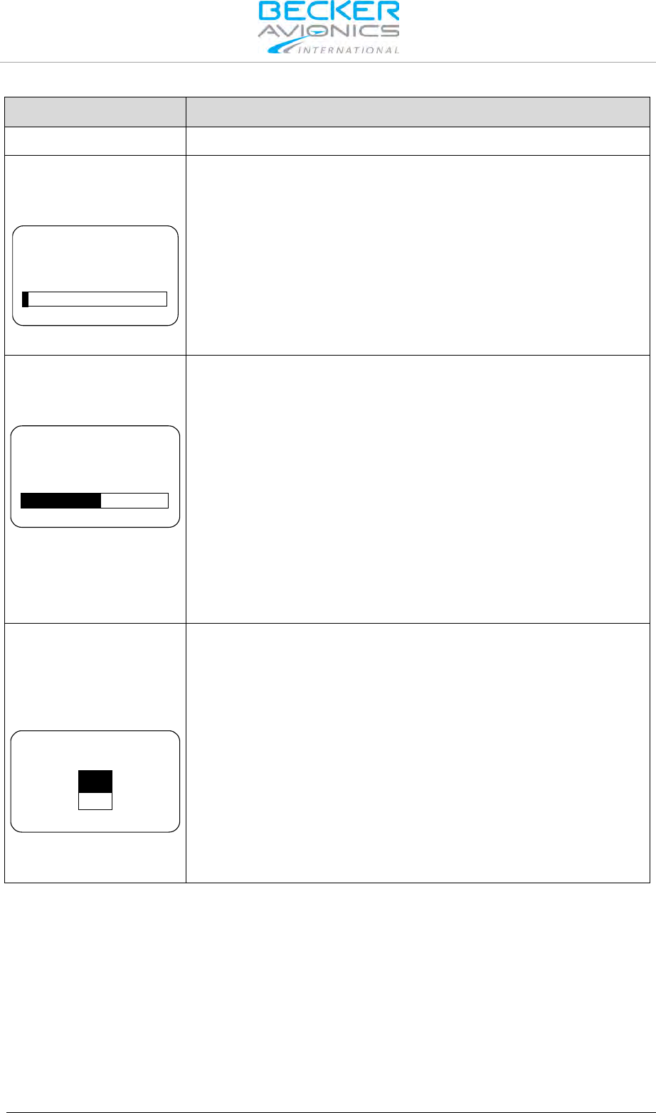
Installation
Configuration Setup
DV14307.03 Issue 04 March 2016 Transceiver Family 620X 65
Display Contents
Description
Note: Menu available on primary controller.
"SCAN HOLD TIME":
The "SCAN HOLD_TIME" is adjustable within the range of
1...60 seconds by turning the "ROTARY ENCODER".
1
SCAN HOLD TIME
The default factory setting is 1.
Note: Menu available on primary controller.
For normal airborne operation it is recommended to leave the
setting at 1.
"SIDETONE ATT":
The sidetone attenuation "SIDETONE ATT" is adjustable within the
range 0…12 dB by turning the "ROTARY ENCODER".
6
SIDETONE ATT
The attenuation relates to the intercom volume.
0dB = sidetone as loud as intercom signal.
12dB = sidetone signal 12 dB less than the intercom signal.
Example: If the intercom volume is set to a very low value, then the
sidetone volume will be reduced in relation to the intercom volume,
irrespective of the sidetone value.
The "SIDETONE ATT" parameter is an additional attenuation of the
sidetone signal in transmit mode.
Note: Menu available on primary controller.
"ERASE CHN MEM":
The 620X transceiver provide two databases to store up to 99 VHF
frequencies identified by channel numbers (CH01 to CH99).
Both data bases, the "User Channels Database" and "Last Channels
Database" can be erased.
NO
YES
ERASE CHN MEM
To erase the data bases;
1. Select "YES" via the "ROTARY ENCODER"
2. Press the "STO" push-button to confirm the selection.
Note: Menu available on primary controller.
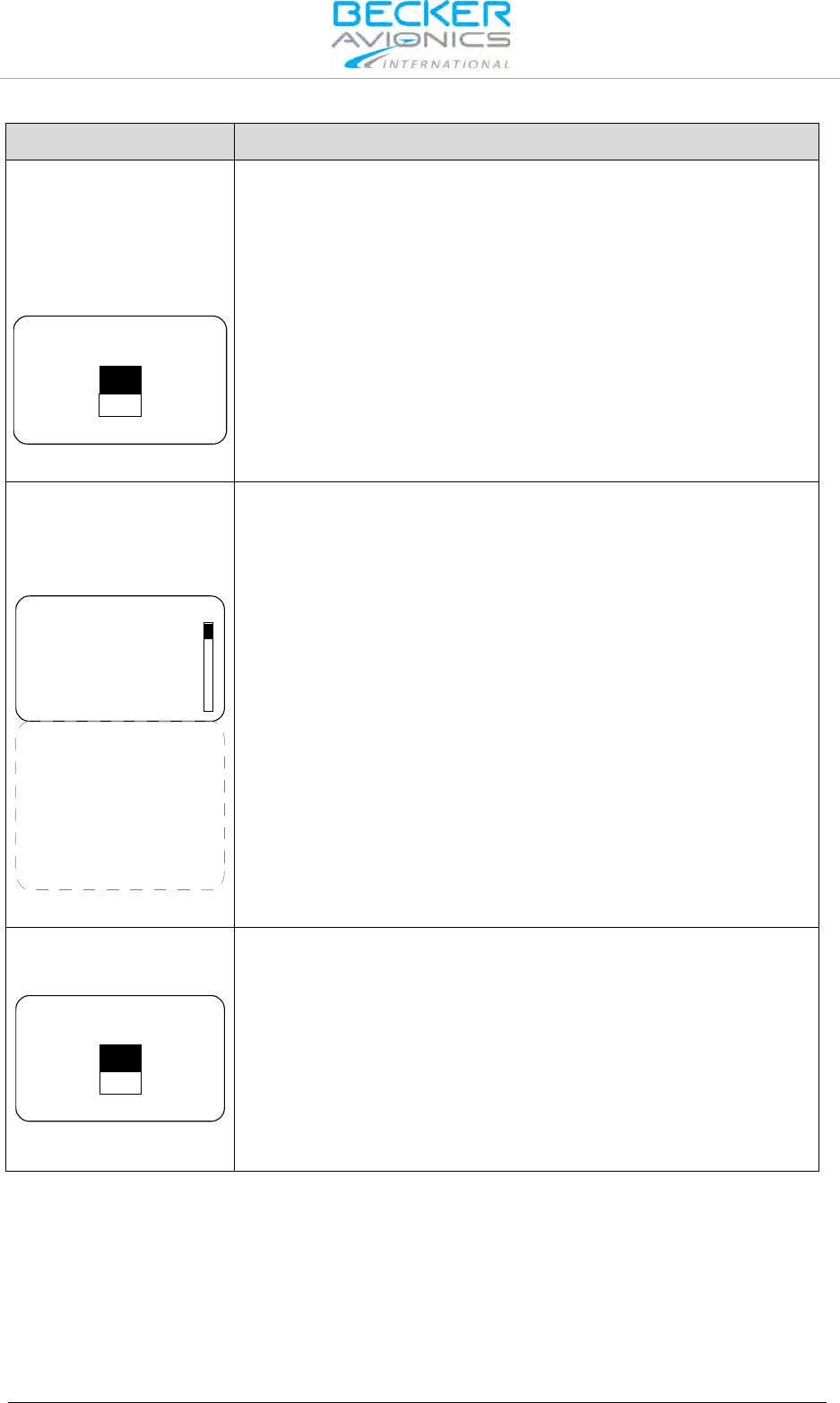
Installation
Configuration Setup
66 Transceiver Family 620X DV14307.03 Issue 04 March 2016
Display Contents
Description
"ERASE FRQ LAB":
The 620X transceiver provides a third database, "FRQUENCY LABELS
DATABASE", containing 99 text labels of max 10 characters each. Text
labels can be assigned to any of the frequencies (CH01 to CH99), the
labels are stored manually.
The "LABELS DATABASE" can be erased.
NO
YES
ERASE FRQ LAB
To erase the data base;
1. Select "YES" via the "ROTARY ENCODER"
2. Press the "STO" push-button to confirm the selection.
Note: Menu available on primary controller.
"FAIL LIST":
This page automatically stores and displays information from all failures
that occur during operation of the 620X.
Used for trouble shooting and failure isolation.
P_NVRAM TEST 0
P_INTERNAL IC 0
P_RXS LOCK 0
P_RECEIVER 0
P_SUPP BLOCK 0
P_OVER TEMP 0
C_INTERNAL IC 0
C_RXS LOCK 0
C_TXS LOCK 0
C_TX POWER 0
C_SUPP BLOCK 0
C_TX OVERLOAD 0
C_OVER TEMP 0
C_STUCK PTT 0
FAIL LIST
1. The display can only show 4 monitored failures types (more are
available).
2. Move the slide bar via the "ROTARY ENCODER" To view additional
failures.
3. "0" means no failure were detected and stored.
4. "1" means that a failure was detected once or several times and
stored.
Note: Menu available on primary controller.
"ERASE FAIL LIST":
To erase all stored failures.
NO
YES
ERASE FAIL LIST
1. Selecting "YES" via the "ROTARY ENCODER".
2. Press the "STO" push-button to confirm.
Erasing the failure list should not be undertaken by the installer. The
failure list will normally be deleted by factory or maintenance shop after
a repair is completed
Note: Menu available on primary controller.

Installation
Configuration Setup
DV14307.03 Issue 04 March 2016 Transceiver Family 620X 67
Display Contents
Description
"RECALL DEF:":
The factory default settings are the settings of the device when it left the
factory after production.
NO
YES
RECALL DEF.
To restore the factory settings;
1. Select "YES" via the "ROTARY ENCODER".
2. PRESS the "STO" push-button to confirm.
Restoring the factory default settings will overwrite all previous
and customized configuration settings!
Note: Menu available on primary controller.

Installation
Factory Default Settings
68 Transceiver Family 620X DV14307.03 Issue 04 March 2016
2.9. Factory Default Settings
Enabled Disabled Selected De-Selected
Setting name
Value
DEVICE INFO
DIMMING INPUT
NONE
BRIGHTNESS
50%
MEMORY OPTIONS
CHANNEL STORE
STORE LAST CHANNEL
MDE PAGES
STANDBY FREQUENCY
BATTERY VOLTAGE
CHANNEL MEMORY
LOW BATT THR
10.5 V AR6201-(X2X)
21.0 V AR6201-(X1X)
CONFIG
TANDEM
AUX_IN
AUTO ISOL IN TX
SCAN BEEP
FREQ CHANGE BEEP
SWAP MIKE IC
IN/OUT CFG1
MICROPHONE 1
STD 1 MIKE
STD 2 MIKE
STD 3 MIKE
DYN MIKE
NONE
MICROPHONE 2
STD 1 MIKE
STD 2 MIKE
STD 3 MIKE
DYN MIKE
NONE
MIC ACTIVATION
BOTH MIKES
OUTPUTS
HEADPHONE 1
HEADPHONE 2
SPEAKER
NONE
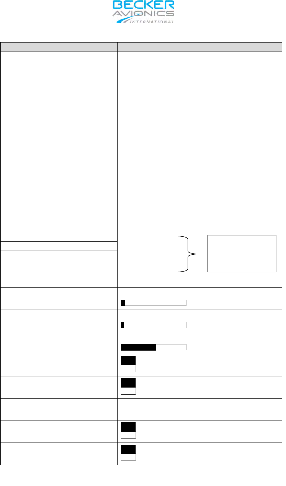
Installation
Factory Default Settings
DV14307.03 Issue 04 March 2016 Transceiver Family 620X 69
Setting name
Value
IN/OUT CFG2
MICROPHONE 1
STD 1 MIKE
STD 2 MIKE
STD 3 MIKE
DYN MIKE
NONE
MICROPHONE 2
STD 1 MIKE
STD 2 MIKE
STD 3 MIKE
DYN MIKE
NONE
MIC ACTIVATION
BOTH MIKES
OUTPUTS
HEADPHONE 1
HEADPHONE 2
SPEAKER
NONE
STD1 MIKE SENS
119 mV
119 mV
3.5 mV
STD2 MIKE SENS
DYN MIKE SENS
SPKR VOL SRC
PRIMARY CH
SECONDARY CH
BOTH
SQUELCH THR
12
SCAN HOLD TIME
1
SIDETONE ATT
6
ERASE CHANNEL MEM
NO
YES
ERASE FREQUENCY LABELS
NO
YES
FAIL LIST
ERASE FAIL LIST
NO
YES
RECALL DEF.
NO
YES
visible depending on
MIKE configuration of
external MIKE Switch
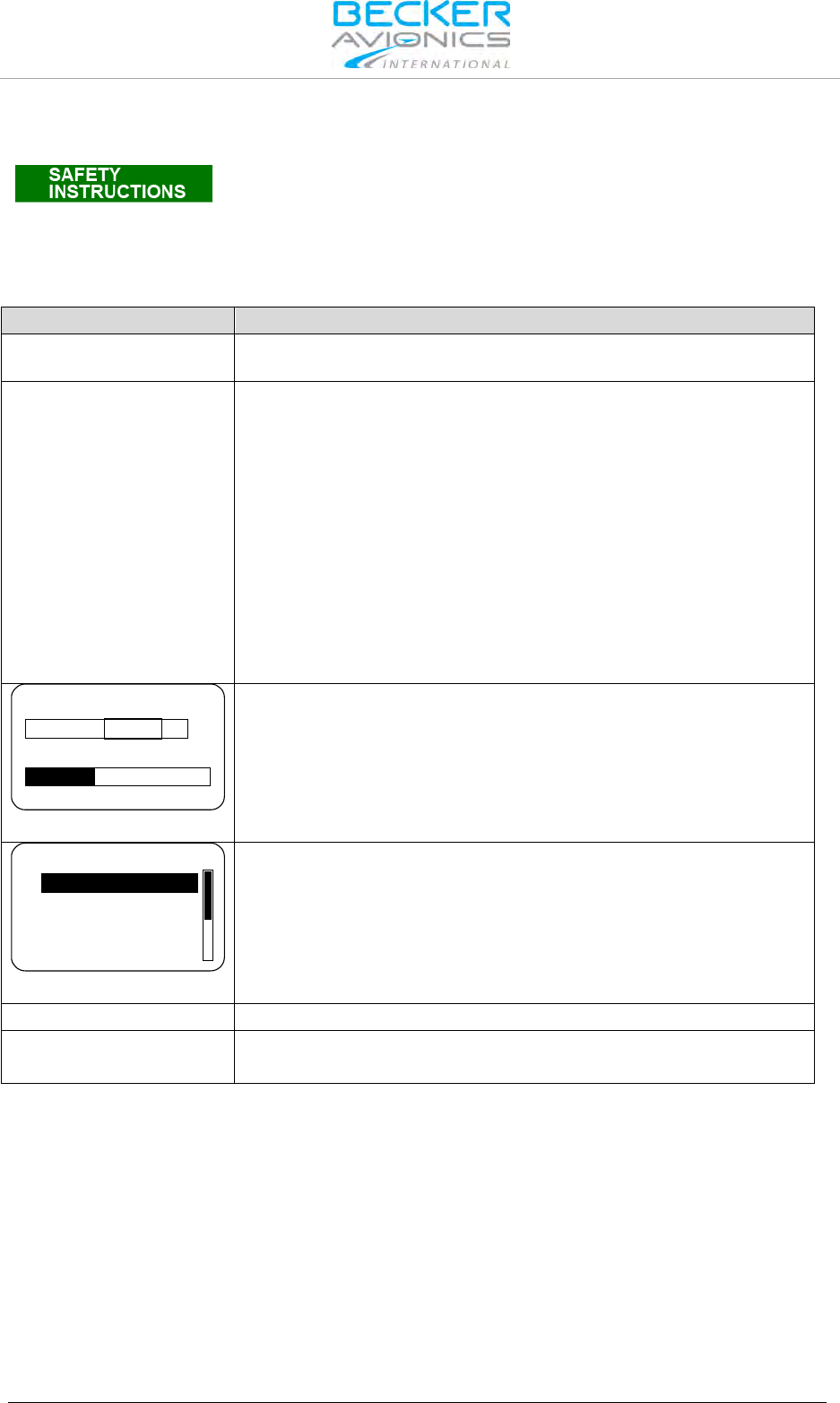
Installation
Wiring Diagrams and Settings
70 Transceiver Family 620X DV14307.03 Issue 04 March 2016
2.10. Wiring Diagrams and Settings
Installation of the unit varies according to aircraft and equipment
design. It is therefore only possible to provide general guidelines in this
section.
2.10.1. Single Seat Glider
2.10.1.1. Configuration Setup
Sub-Menu
Function: / Selection
"SPKR VOLUME
SOURCE
PRIMARY CH
"IN/OUT CFG1":
"MICROPHONE 1": NONE
"MICROPHONE 2": DYN_MIKE
"BOTH MIKES": Enabled
"HEADPHONE 1": Enabled
"SPEAKER": Enabled
With /MIKE_SW not connected (/MIKE_SW input is set to Inactive
state) it is only necessary to configure IN/OUT CFG1.
If only headphone(s) are used, SPEAKER can be disabled by
selecting NONE.
If only speaker is used, disable HDPH 1.
17 dB 3.5 mV
VU
DYN MIKE SENS
Adjust DYN MIKE SENS to proper level
TANDEM
AUX INPUT
AUX AUTO MUTE
AUTO ISOL IN TX
CONFIGURATION
If you want to use an auxiliary input we recommend to configure
AUX AUTO MUTE In CONFIG menu set:
AUX IN – ENABLE
AUX AUTO MUTE - ENABLE
"IN/OUT FG2"
N/A
Remarks
Permanent speaker sign is visible on LCD screen.
VOX operation suppressed.
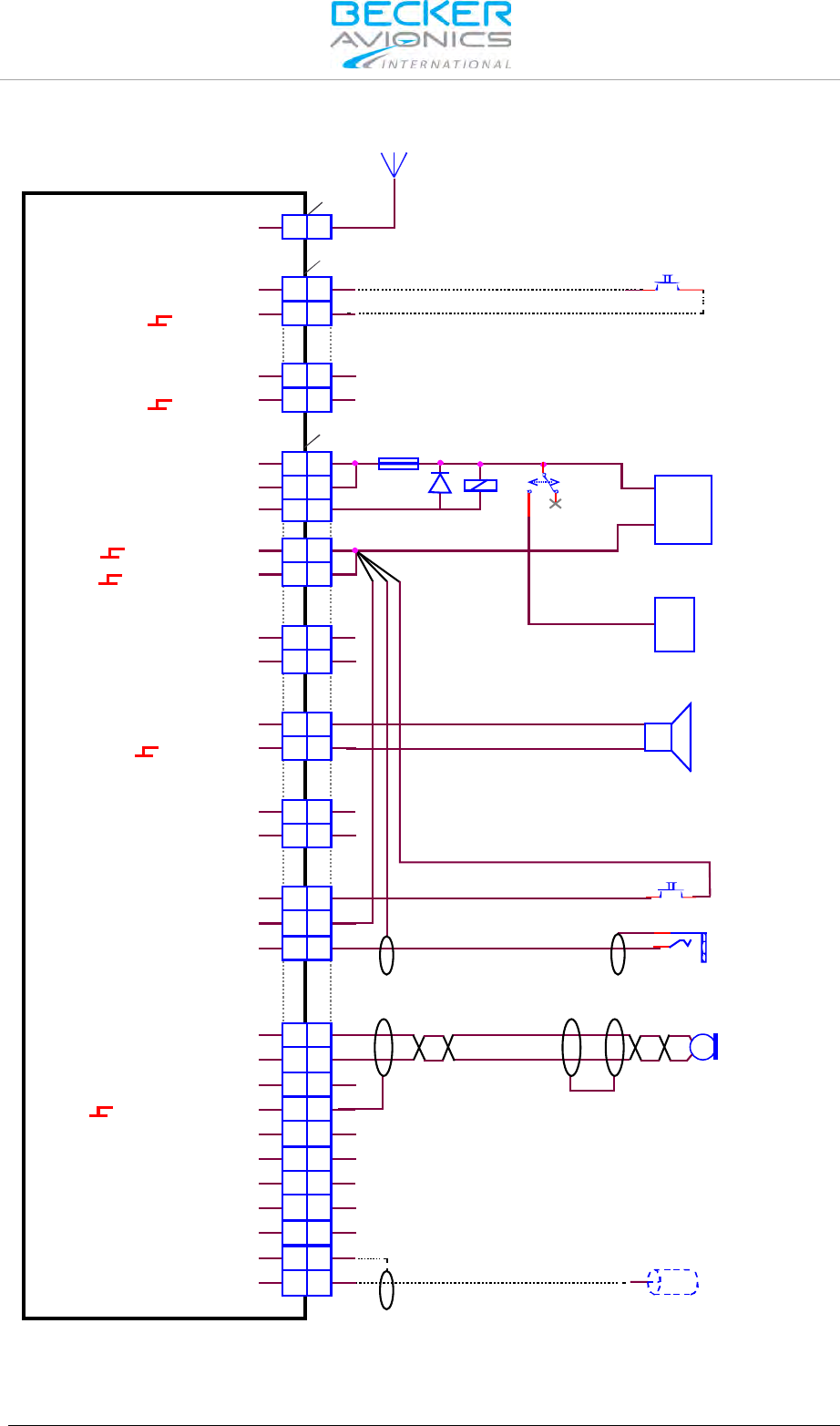
Installation
Wiring Diagrams and Settings
DV14307.03 Issue 04 March 2016 Transceiver Family 620X 71
2.10.1.2. Wiring Diagrams Single Seat Glider
J3
J1
P1
A
A
12 12
21 21
24
23 23
24
12 12
11 11
24 24
13 13
25 25
23 23
10 10
14 14
7 7
16 16
17 17
33
2 2
5 5
66
18 18
88
9 9
21 21
20 20
19 19
44
15 15
22 22
1 1
ANTENNA
/EXT_SO
ILL_HI
SPK_HI
SPK_LO
/IC
AGC_OUT
/PTT1
HDPH1_B
HDPH1_A
HDPH2_B
HDPH2_A
MIKE_DYN_LO
MIKE_DYN_HI
MIKE_STD1_HI
MIKE_STD2_HI
MIKE_STD3_HI
LINE_OUT
AF_AUX_IN_LO
AF_AUX_IN_HI
MIKE_STD1_LO
ILL_LO
/MIKE_SW
D_GND
D_GND
P_SUPP
P_SUPP_GND
P_SUPP_GND
P_SUPP
/PWR_EVAL
AR6201-(X1X) / AR6203-(X1X)
AR6201-(X2X) / AR6203-(X2X)
ANTENNA
Frequency Exchange
(Remote Flip-Flop)
optional
AWG20
Relaxed
Energized
7.5 A +
-
AWG20
Battery
12 V
Switched supply
SPEAKER
4 Ohm
AWG20
PTT
Auxiliary Audio Input
optional
MICROPHONE
Dynamic Mike
PJ055
Earphone Pilot
Note: mount the jacks (earphone)
isolated from aircraft frame
Figure 2-19: Wiring for Single Seat Glider
Note: Frequency exchange switch and switched supply relay are optional
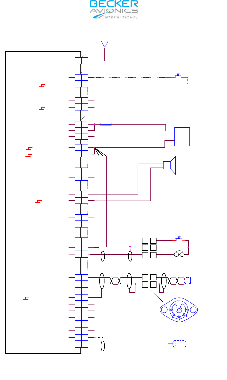
Installation
Wiring Diagrams and Settings
72 Transceiver Family 620X DV14307.03 Issue 04 March 2016
2.10.1.3. Wiring Diagrams Single Seat Glider 5-pol DIN Jack
J3
J1
P1
A
A
12 12
21 21
24
23 23
24
12 12
11 11
24 24
13 13
25 25
23 23
10 10
14 14
7 7
55
11
33
22
44
16 16
17 17
33
2 2
5 5
66
18 18
88
9 9
21 21
20 20
19 19
44
15 15
22 22
1 1
ANTENNA
/EXT_SO
ILL_HI
SPK_HI
SPK_LO
/IC
AGC_OUT
/PTT1
HDPH1_B
HDPH1_A
HDPH2_B
HDPH2_A
MIKE_DYN_LO
MIKE_DYN_HI
MIKE_STD1_HI
MIKE_STD2_HI
MIKE_STD3_HI
LINE_OUT
AF_AUX_IN_LO
AF_AUX_IN_HI
MIKE_STD1_LO
ILL_LO
/MIKE_SW
D_GND
D_GND
P_SUPP
P_SUPP_GND
P_SUPP_GND
P_SUPP
/PWR_EVAL
AR6201-(X1X) / AR6203-(X1X)
AR6201-(X2X) / AR6203-(X2X)
ANTENNA
Frequency Exchange
(Remote Flip-Flop)
optional
AWG20
7.5 A +
-
AWG20
Battery
12 V
SPEAKER
4 Ohm
AWG20
PTT
PHONE
Auxiliary Audio Input
Connector Wiring side
optional
MICROPHONE
Dynamic Mike
Figure 2-20: Wiring for Single Seat Glider (5-pol DIN Jack)
Note: Frequency exchange switch is optional

Installation
Wiring Diagrams and Settings
DV14307.03 Issue 04 March 2016 Transceiver Family 620X 73
2.10.2. Twin Seat Motor Glider
2.10.2.1. Configuration Setup
Sub-Menu
Function: / Selection
"SPKR VOLUME
SOURCE
BOTH
"CONFIGURATION"
"SWAP MIKE IC" : Disabled
"IN/OUT CFG1"
(/MIKE_SW open):
"MICROPHONE 1" : STD_1 MIKE
"MICROPHONE 2" : NONE
"BOTH MIKES" : Enabled
"HEADPHONE 1" : Enabled
"SPEAKER" : Disabled
"IN/OUT CFG2"
(/MIKE_SW closed):
"MICROPHONE 1" : NONE
"MICROPHONE 2" : DYN_MIKE
"BOTH MIKES" : Enabled
"HEADPHONE 1" : Enabled
"SPEAKER" : Enabled
Remarks
The external switch (connected to pin J1-24 /MIKE_SW) has the
following functions:
Open:
• Standard microphone is selected.
• Speaker is disabled.
• Intercom via VOX is possible.
Closed:
• Dynamic microphone is selected.
• Speaker is enabled.
• No Intercom via VOX is possible.
• Permanent speaker sign is visible on LCD screen.

Installation
Wiring Diagrams and Settings
74 Transceiver Family 620X DV14307.03 Issue 04 March 2016
2.10.2.2. Wiring Diagram Twin Seat Motor Glider
J3
J1
P1
A
A
12 12
21 21
24
23 23
24
12 12
11 11
24 24
13 13
25 25
23 23
10 10
14 14
7 7
16 16
17 17
33
2 2
5 5
66
18 18
88
9 9
21 21
20 20
19 19
44
15 15
22 22
1 1
ANTENNA
/EXT_SO
ILL_HI
SPK_HI
SPK_LO
/IC
AGC_OUT
/PTT1
HDPH1_B
HDPH1_A
HDPH2_B
HDPH2_A
MIKE_DYN_LO
MIKE_DYN_HI
MIKE_STD1_HI
MIKE_STD2_HI
MIKE_STD3_HI
LINE_OUT
AF_AUX_IN_LO
AF_AUX_IN_HI
MIKE_STD1_LO
ILL_LO
/MIKE_SW
D_GND
D_GND
P_SUPP
P_SUPP_GND
P_SUPP_GND
P_SUPP
/PWR_EVAL
AR6201-(X1X) / AR6203-(X1X)
AR6201-(X2X) / AR6203-(X2X)
ANTENNA
Frequency Exchange
(Remote Flip-Flop)
optional
Standard Mike
SPEAKER Off
Dynamic Mike
SPEAKER On
AWG20
7.5 A +
-
AWG20
SUPPLY
14 V / 28 V
SPEAKER 2
8 Ohm
SPEAKER 1
8 Ohm
AWG20
Manual Intercom (optional)
Intercom Off
Pilot
Intercom On
Intercom Off
Copilot
Intercom On
PTT Pilot
PT Copilot
Earphone Pilot
PJ055
Earphone Copilot
PJ055
PJ068
Standard Mike
Pilot
PJ068
Standard Mike
Copilot
Auxiliary Audio Input
Note: mount the jacks
(earphone&mike) isolated from aircraft frame
optional
MICROPHONE
Dynamic Mike Pilot
MICROPHONE
Dynamic Mike Copilot
Figure 2-21: Wiring for Twin Seat Motor Glider

Installation
Wiring Diagrams and Settings
DV14307.03 Issue 04 March 2016 Transceiver Family 620X 75
2.10.3. General Aviation (GA) Aircraft
2.10.3.1. Configuration Setup (using Standard Microphones)
Sub-Menu
Function: / Selection
"SPKR VOLUME
SOURCE
BOTH
"CONFIGURATION"
"SWAP MIKE IC" : Disabled
"IN/OUT CFG1"
(/MIKE_SW open):
"MICROPHONE 1" : STD1_MIKE
"MICROPHONE 2" : NONE
"BOTH MIKES" : Disabled
"HEADPHONE 1" : Enabled
"SPEAKER" : Disabled
"IN/OUT CFG2"
(/MIKE_SW closed):
"MICROPHONE 1" : STD1_MIKE
"MICROPHONE 2" : NONE
"BOTH MIKES" : Disabled
"HEADPHONE 1" : Enabled
"SPEAKER" : Enabled
Remarks
The external switch (connected to pin J1-24 /MIKE_SW) has the
following functions:
Open:
• Speaker is disabled,
• Intercom via VOX is possible.
Closed:
• Speaker is enabled
• No intercom via VOX is possible
• Permanent speaker sign is visible on LCD screen.
• The standard microphone input is selected regardless of the
position of the external switch.
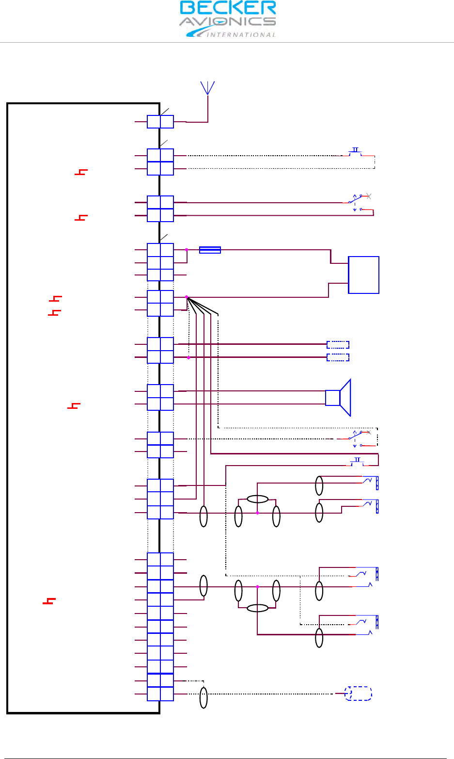
Installation
Wiring Diagrams and Settings
76 Transceiver Family 620X DV14307.03 Issue 04 March 2016
2.10.3.2. Wiring Diagram General Aviation GA Using Standard Microphones
J3
J1
P1
A
A
12 12
21 21
24
23 23
24
12 12
11 11
24 24
13 13
25 25
23 23
10 10
14 14
7 7
16 16
17 17
33
2 2
5 5
66
18 18
88
9 9
21 21
20 20
19 19
44
15 15
22 22
1 1
ANTENNA
/EXT_SO
ILL_HI
SPK_HI
SPK_LO
/IC
AGC_OUT
/PTT1
HDPH1_B
HDPH1_A
HDPH2_B
HDPH2_A
MIKE_DYN_LO
MIKE_DYN_HI
MIKE_STD1_HI
MIKE_STD2_HI
MIKE_STD3_HI
LINE_OUT
AF_AUX_IN_LO
AF_AUX_IN_HI
MIKE_STD1_LO
ILL_LO
/MIKE_SW
D_GND
D_GND
P_SUPP
P_SUPP_GND
P_SUPP_GND
P_SUPP
/PWR_EVAL
AR6201-(X1X) / AR6203-(X1X)
AR6201-(X2X) / AR6203-(X2X)
ANTENNA
Frequency Exchange
(Remote Flip-Flop)
optional
SPEAKER Off
SPEAKER On
AWG20
7.5 A +
-
AWG20
SUPPLY
14 V / 28 V
Dimming Control
14 V / 28 V
GND
SPEAKER
4 Ohm
AWG20
Manual Intercom (optional) Intercom Off
Intercom On
PTT
Earphone Pilot
PJ055
Earphone Copilot
PJ055
PJ068
Standard Mike
Pilot
PJ068
Standard Mike
Copilot
Auxiliary Audio Input
Note: mount the jacks
(earphone&mike) isolated from aircraft frame
optional
Figure 2-22: Wiring for Usage of Standard Hand Mikes, Earphones and Speaker

Installation
Wiring Diagrams and Settings
DV14307.03 Issue 04 March 2016 Transceiver Family 620X 77
2.10.4. Individual Dual Headset Configuration (two IC Circuit)
2.10.4.1. Configuration Setup
Sub-Menu
Function: / Selection
"SPKR VOLUME
SOURCE
BOTH
"CONFIGURATION"
"SWAP MIKE IC" : Disabled
"IN/OUT CFG1"
(/MIKE_SW open):
"MICROPHONE 1" : STD1_MIKE
"MICROPHONE 2" : STD2_MIKE
"BOTH MIKES" : Disabled
"HEADPHONE 1" : Enabled
"HEADPHONE 2" : Enabled
"SPEAKER" : Disabled
The standard microphone remains selected for both configurations
"IN/OUT CFG2"
(/MIKE_SW closed):
"MICROPHONE 1" : STD1_MIKE
"MICROPHONE 2" : STD3_MIKE
"BOTH MIKES" : Enabled
"HEADPHONE 1" : Disabled
"SPEAKER" : Enabled
Remarks
The external switch (connected to pin J1-24 /MIKE_SW) has the
following functions:
Open:
• Headset 1 for pilot selected (STD1)
• Headset 2 for co-pilot selected (STD2)
• Speaker is disabled,
• Intercom via VOX is possible.
Closed:
• Headset 1 selected (STD1)
• Headset 2 disconnected (STD2)
• Hand mike selected (STD3)
• Speaker is enabled
• No intercom via VOX is possible
• If PTT is active then speaker is muted.
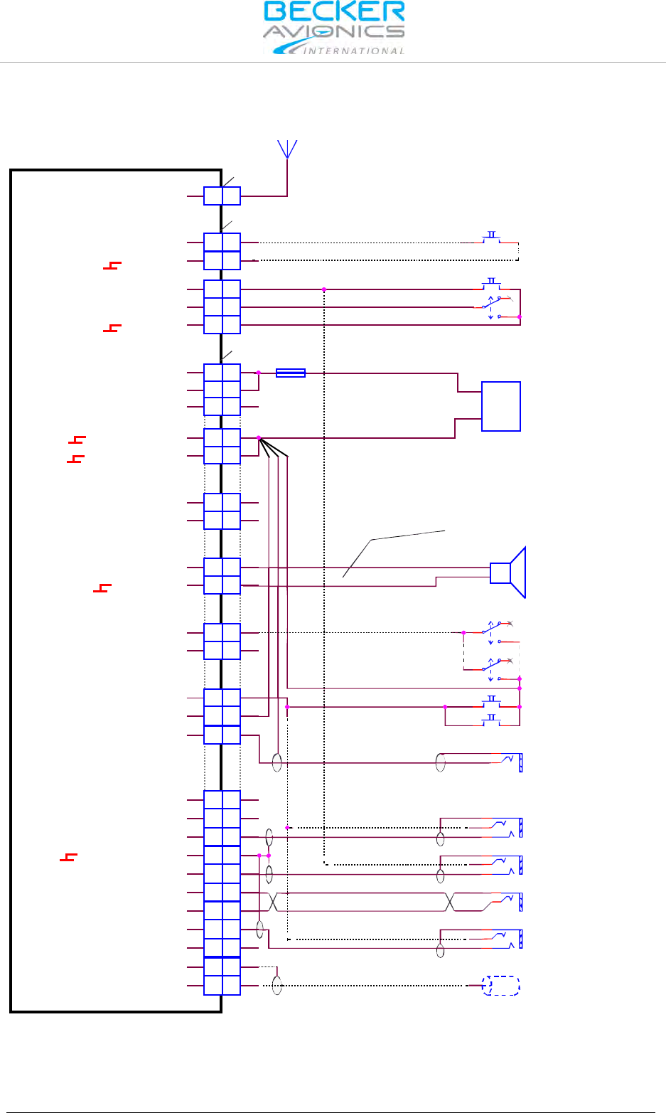
Installation
Wiring Diagrams and Settings
78 Transceiver Family 620X DV14307.03 Issue 04 March 2016
2.10.4.2. Wiring Diagram Individual Dual Headset Configuration - two IC Circuit
ANTENNA
AWG20
7.5 A +
-
AWG20
AWG20
Manual Intercom (optional)
SPEAKER
4 Ohm
SUPPLY
14 V / 28 V
SPEAKER Off
SPEAKER On
PTT Copilot
Frequency Exchange
(Remote Flip-Flop)
optional
Intercom Off
Pilot
Intercom On
Intercom Off
CoPilot
Intercom On
PTT Pilot
PTT Hand Mike
Earphone Pilot
PJ055
Earphone Copilot
PJ055
PJ068
Standard Mike Pilot
PJ068
Standard Mike Copilot
PJ068
Standard Mike Handmike
Auxiliary Audio Input
Note: mount the jacks (earphone&mike)
isolated from aircraft frame
optional
J3
J1
P1
A
A
12 12
21 21
5 5
24
23 23
24
12 12
11 11
24 24
13 13
25 25
23 23
10 10
14 14
7 7
16 16
17 17
33
2 2
5 5
66
18 18
88
9 9
21 21
20 20
19 19
44
15 15
22 22
1 1
ANTENNA
/EXT_SO
/PTT2
ILL_HI
SPK_HI
SPK_LO
/IC
AGC_OUT
/PTT1
HDPH1_B
HDPH1_A
HDPH2_B
HDPH2_A
MIKE_DYN_LO
MIKE_DYN_HI
MIKE_STD1_HI
MIKE_STD2_HI
MIKE_STD3_HI
LINE_OUT
AF_AUX_IN_LO
AF_AUX_IN_HI
MIKE_STD1_LO
ILL_LO
/MIKE_SW
D_GND
D_GND
P_SUPP
P_SUPP_GND
P_SUPP_GND
P_SUPP
/PWR_EVAL
AR6201-(X1X) / AR6203-(X1X)
AR6201-(X2X) / AR6203-(X2X)
Figure 2-23: Dual wiring for Usage of Standard Hand Mikes, Earphones and Speaker

Installation
Wiring Diagrams and Settings
DV14307.03 Issue 04 March 2016 Transceiver Family 620X 79
2.10.5. Twin Seat with AR620X Tandem Configuration
2.10.5.1. Configuration Setup
Sub-Menu
Function: / Selection
"SPKR VOLUME
SOURCE
BOTH
"CONFIGURATION"
"SWAP MIKE IC" : Disabled
"IN/OUT CFG1"
(/MIKE_SW open):
"MICROPHONE 1" : STD1_MIKE
"MICROPHONE 2" : NONE
"BOTH MIKES" : Enabled
"HEADPHONE 1" : Enabled
"SPEAKER" : Disabled
If only headphone(s) are used, SPEAKER can be disabled by selecting
NONE.
If only speaker is used, HDPH 1 can be disabled.
The standard microphone remains selected for both configurations
"IN/OUT CFG2"
(/MIKE_SW closed):
"MICROPHONE 1" : STD1_MIKE
"MICROPHONE 2" : NONE
"BOTH MIKES" : Enabled
"HEADPHONE 1" : Enabled
"SPEAKER" : Enabled
Remarks
The external switch (connected to pin J1-24 /MIKE_SW) has the
following functions:
Open:
• Headset 1 for pilot selected
• Headset 2 for co-pilot selected
• Speaker is disabled,
• Intercom via VOX is possible.
Closed:
• Headset 1 selected (STD1)
• Headset 2 disconnected (STD2)
• Hand mike selected (STD3)
• Speaker is enabled
• No intercom via VOX is possible
• If PTT is active then speaker is muted.

Installation
Wiring Diagrams and Settings
80 Transceiver Family 620X DV14307.03 Issue 04 March 2016
2.10.5.2. Wiring Diagram Twin Seat with AR620X Tandem Configuration
AWG20
7.5 A 3 A
AWG20
AWG20
AWG20
+
-
SPEAKER
4 Ohm
SUPPLY
14 V / 28 V
SPEAKER Off
SPEAKER On
PTT Copilot
Manual Intercom (optional)
PTT Pilot
Intercom Off
Pilot
Intercom On
Intercom Off
Copilot
Intercom On
PTT Hand Mike
Frequency Exchange
(Remote Flip-Flop)
optional
PJ055
Earphone Copilot
PJ055
Earphone Pilot
PJ055
Earphone Passenger1
PJ068
Standard Mike Copilot
PJ068
Standard Mike Pilot
PJ068
Standard Mike Handmike
Auxiliary Audio Input
Note: mount the jacks (earphone&mike)
isolated from aircraft frame
optional
AR6201-(X1X) / AR6203-(X1X)
AR6201-(X2X) / AR6203-(X2X)
ANTENNA
J3
J1
P1
P1
AA
12 12
21 21
5 5
24 24
23 23
12 12
11 11
24 24
8 8
15 15
7 7
14 14
25 25 9 9
13 13
11 11
2 2
1 1
4 4
5 5
1 1
14 14
7 7
16 16
17 17
3 3
2 2
5 5
6 6
18 18
8 8
9 9
22 22
20 20
19 19
15 15
21 21
4 4
23 23
10 10
13 13
25 25
ILL_HI
SPK_HI
SPK_LO
/IC
AGC_OUT
/PTT1
HDPH1_B
HDPH1_A
HDPH2_B
HDPH2_A
MIKE_DYN_LO
MIKE_DYN_HI
MIKE_STD1_HI
MIKE_STD2_HI
MIKE_STD3_HI
LINE_OUT
AF_AUX_IN_LO
AF_AUX_IN_HI
MIKE_STD_LO
ILL_LO
P_SUPP
P_SUPP_GND
P_SUPP_GND
P_SUPP
/PWR_EVAL
ANTENNA
/EXT_SO
/PTT2
/MIKE_SW
D_GND
D_GND
RX1+
RX1-
TX1+
TX1-
/ON
TX0_422+
TX0_422-
RX0_422+
RX0_422-
GND
/EXT_ON
SUPP_IN
RCU6201-(X1X)
Figure 2-24: Wiring for Twin Seat with AR6201 Tandem Configuration

Installation
Wiring Diagrams and Settings
DV14307.03 Issue 04 March 2016 Transceiver Family 620X 81
2.10.6. Aircraft with four Seats (no TANDEM)
2.10.6.1. Configuration Setup
Sub-Menu
Function: / Selection
"SPKR VOLUME
SOURCE
BOTH
"CONFIGURATION"
"SWAP MIKE IC" : Disabled
"IN/OUT CFG1"
(/MIKE_SW open):
"MICROPHONE 1" : STD1_MIKE
"MICROPHONE 2" : STD3_MIKE
"BOTH MIKES" : Enabled
"HEADPHONE 1" : Disabled
"SPEAKER" : Enabled
If only headphone(s) are used, SPEAKER can be disabled by selecting
NONE.
If only speaker is used, HDPH 1 can be disabled.
The standard microphone remains selected for both configurations
"IN/OUT CFG2"
(/MIKE_SW closed):
"MICROPHONE 1" : STD1_MIKE
"MICROPHONE 2" : STD2_MIKE
"BOTH MIKES" : Disabled
"HEADPHONE 1" : Enabled
"HEADPHONE 2" : Enabled
"SPEAKER" : Disabled
Remarks
The external switch (connected to pin J1-24 /MIKE_SW) has the
following functions:
Open:
• Headset 1 and 2 for pilot and co-pilot selected
• Headset 3 and 4 for passengers selected
• Speaker is disabled,
• Intercom via VOX is possible.
Closed:
• Headset 1 and 2 for pilot and co-pilot selected
• Headset 3 and 4 disconnected
• Hand mike selected (STD3)
• Speaker is enabled
• No intercom via VOX is possible
• If PTT is active then speaker is muted.
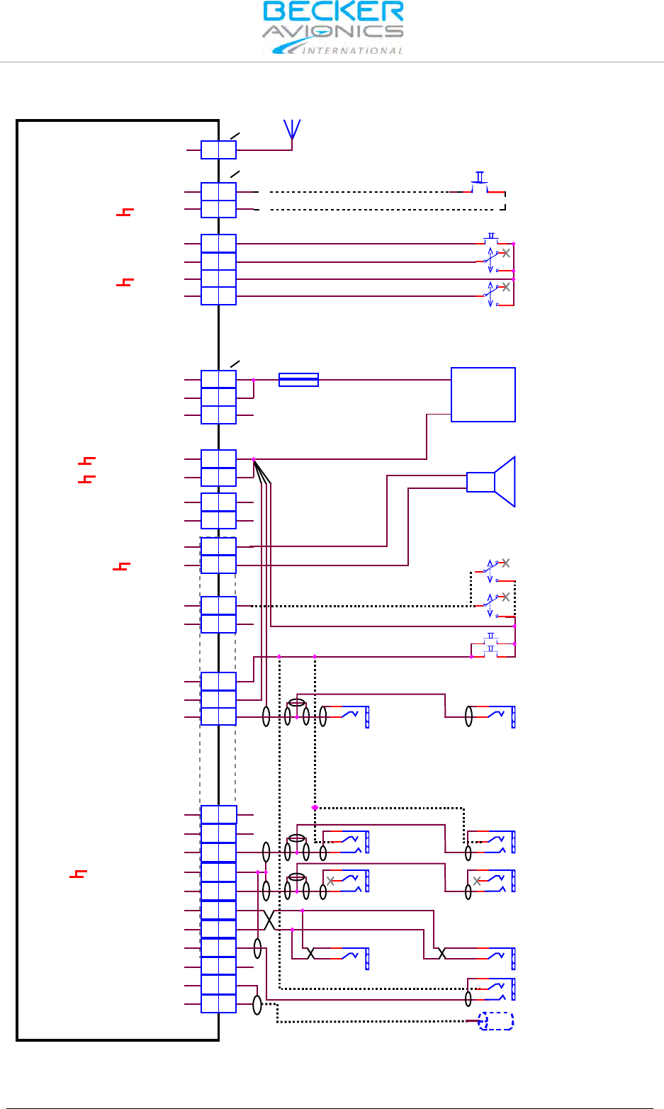
Installation
Wiring Diagrams and Settings
82 Transceiver Family 620X DV14307.03 Issue 04 March 2016
2.10.6.2. Wiring Diagram Aircraft with four Seats - no TANDEM
AWG20
7.5 A
AWG20
AWG20
+
-
SPEAKER
4 Ohm
SUPPLY
14 V / 28 V
SPEAKER Off
SPEAKER On
ISOL Off
ISOL On
PTT Copilot
Manual Intercom (optional)
PTT Copilot
Intercom Off
Pilot
Intercom On
Intercom Off
Copilot
Intercom On
PTT Hand Mike
Frequency Exchange
(Remote Flip-Flop)
optional
PJ055
Earphone Pilot
PJ055
Earphone Copilot
PJ055
Earphone Passenger2
PJ055
Earphone Passenger1
PJ068
Standard Passenger1
PJ068
Standard Passenger2
PJ068
Standard Mike Copilot
PJ068
Standard Mike
Pilot
PJ068
Standard Mike Handmike
Auxiliary Audio Input
Note: mount the jacks (earphone&mike)
isolated from aircraft frame
optional
AR6201-(X1X) / AR6203-(X1X)
AR6201-(X2X) / AR6203-(X2X)
ANTENNA
J3
J1
P1
AA
12 12
21 21
5 5
24 24
23 23
20 20
12 12
11 11
24 24
1 1
14 14
7 7
16 16
17 17
3 3
2 2
5 5
6 6
18 18
8 8
9 9
22 22
20 20
19 19
15 15
21 21
4 4
23 23
10 10
13 13
25 25
ILL_HI
SPK_HI
SPK_LO
/IC
AGC_OUT
/PTT1
HDPH1_B
HDPH1_A
HDPH2_B
HDPH2_A
MIKE_DYN_LO
MIKE_DYN_HI
MIKE_STD1_HI
MIKE_STD2_HI
MIKE_STD3_HI
LINE_OUT
AF_AUX_IN_LO
AF_AUX_IN_HI
MIKE_STD_LO
ILL_LO
P_SUPP
P_SUPP_GND
P_SUPP_GND
P_SUPP
/PWR_EVAL
ANTENNA
/EXT_SO
/PTT2
/MIKE_SW
D_GND
D_GND
/ISOL
Figure 2-25: Wiring for Aircraft with Four Seats (no TANDEM)

Installation
Wiring Diagrams and Settings
DV14307.03 Issue 04 March 2016 Transceiver Family 620X 83
2.10.7. Installation with RT6201 and RCU6201
RT6201 with primary controller RCU6201 can be used in all presented installation wirings. RT6201
with RCU6201 replace a AR620X. The connection between RT6201 and RCU6201 is shown in the
wiring diagram below.
2.10.7.1. Wiring Diagram with RT6201 and RCU6201
ANTENNA
7.5 A
3 A
AWG20
AWG20
Frequency Exchange
(Remote Flip-Flop)
optional
J3
J1
P1
P1
ANTENNA
/ON
RX2+
RX2-
TX2+
TX2-
/EXT_ON
/EXCH_CH
TX0_422+
TX0_422-
RX0_422+
RX0_422-
GND
SUPP_IN
A
A
24 24
12 12
11 11
13 13
25 25 13 13
15 15
1 1
2 2
4 4
5 5
9 9
11 11
25 25
10 10
3 3
2 2
99
RT6201-(X1X) / RT6201-(X2X)
RCU6201-(X1X)
P_SUPP
P_SUPP
/PWR_EVAL
P_SUPP_GND
P_SUPP_GND
+
-
SUPPLY
14 V / 28 V
Figure 2-26 Wiring for RT6201 with RCU6201 as Primary Controller

Installation
Wiring Diagrams and Settings
84 Transceiver Family 620X DV14307.03 Issue 04 March 2016
2.10.8. Aircraft with Intercom System
2.10.8.1. Configuration Setup
Sub-Menu
Function: / Selection
"SPKR VOLUME SOURCE
BOTH
"CONFIGURATION"
"SWAP MIKE IC" : Disabled
"IN/OUT CFG1":
"MICROPHONE 1" : STD1_MIKE
"MICROPHONE 2" : NONE
"BOTH MIKES" : Enabled
"HEADPHONE 1" : Enabled
"SPEAKER" : Disabled
"IN/OUT FG2"
"MICROPHONE 1" : STD1_MIKE
"MICROPHONE 2" : NONE
"BOTH MIKES" : Enabled
"HEADPHONE 1" : Enabled
"SPEAKER" : Enabled
Remarks
The same configuration applies for balanced and unbalanced wiring.
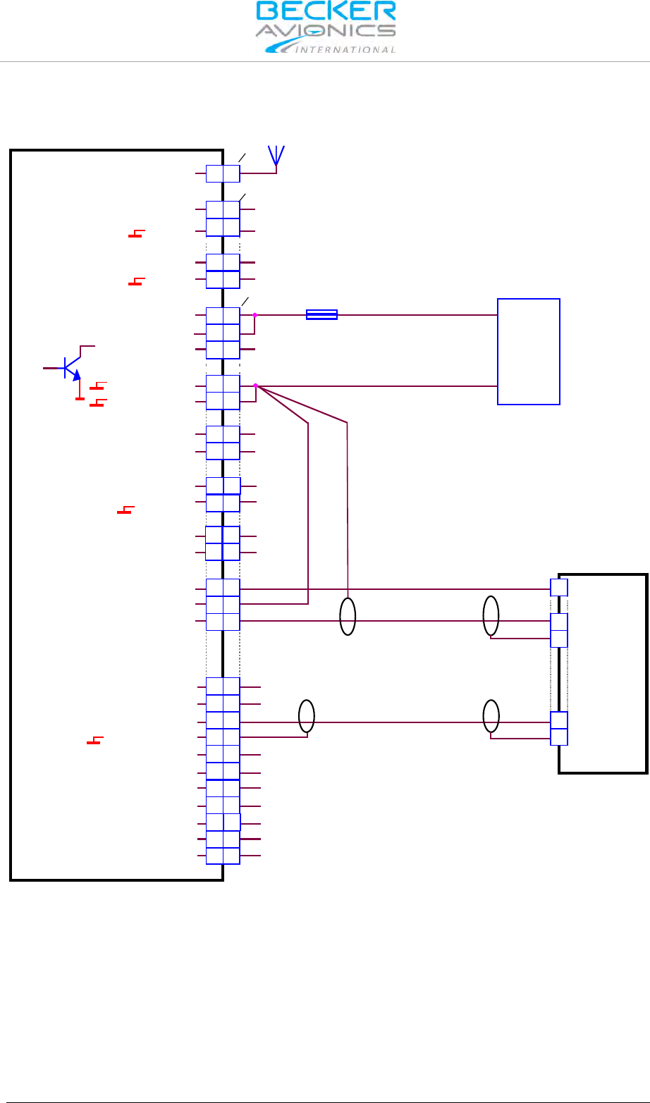
Installation
Wiring Diagrams and Settings
DV14307.03 Issue 04 March 2016 Transceiver Family 620X 85
2.10.8.2. Wiring Diagram Aircraft with Intercom System unbalanced
AR6201-(X1X) / AR6203-(X1X)
AR6201-(X2X) / AR6203-(X2X)
ANTENNA
J3
J1
P1
ANTENNA
/EXT_SO
D_GND
/MIKE_SW
D_GND
HDPH1_B
HDPH1_A
P_SUPP
P_SUPP_GND
P_SUPP_GND
ILL_HI
ILL_LO
SPK_HI
SPK_LO
/IC
AGC_OUT
/PTT1
P_SUPP
/PWR_EVAL
A
A
23 23
25 25
10 10
1 1
14 14
7 7
16 16
12 12
21 21
23 23
17 17
12 12
11 11
24 24
3 3
2 2
5 5
6 6
18 18
88
9 9
2222
2020
19 19
1515
21
MIKE_DYN_LO
MIKE_DYN_HI
MIKE_STD1_HI
MIKE_STD_LO
MIKE_STD2_HI
MIKE_STD3_HI
LINE_OUT
AF_AUX_IN_LO
AF_AUX_IN_IN
HDPH2_B
HDPH2_A
21
44
1313
24 24
+
-
SUPPLY
14 V / 28 V
Intercom System
AWG20
7.5 A
AWG20
PIN N
PIN N
PIN N
PIN N
PIN N
Figure 2-27: Wiring for Aircraft with Intercom System (unbalanced)
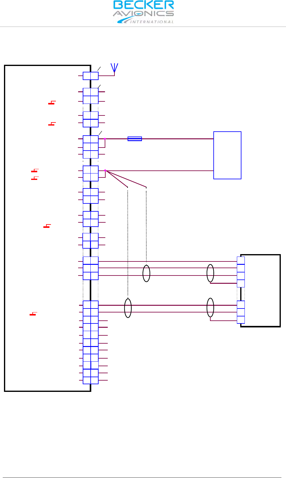
Installation
Wiring Diagrams and Settings
86 Transceiver Family 620X DV14307.03 Issue 04 March 2016
2.10.8.3. Wiring Diagram Aircraft with Intercom System Balanced
AR6201-(X1X) / AR6203-(X1X)
AR6201-(X2X) / AR6203-(X2X)
ANTENNA
J3
J1
P1
ANTENNA
/EXT_SO
D_GND
/MIKE_SW
D_GND
HDPH1_B
HDPH1_A
P_SUPP
P_SUPP_GND
P_SUPP_GND
ILL_HI
ILL_LO
SPK_HI
SPK_LO
/IC
AGC_OUT
/PTT1
P_SUPP
/PWR_EVAL
A
A
23 23
25 25
10 10
1 1
14 14
7 7
16 16
12 12
21 21
23 23
17 17
12 12
11 11
24 24
3 3
2 2
5 5
6 6
18 18
88
9 9
2222
2020
19 19
1515
21
MIKE_DYN_LO
MIKE_DYN_HI
MIKE_STD1_HI
MIKE_STD_LO
MIKE_STD2_HI
MIKE_STD3_HI
LINE_OUT
AF_AUX_IN_LO
AF_AUX_IN_IN
HDPH2_B
HDPH2_A
21
44
1313
24 24
+
-
SUPPLY
14 V / 28 V
Intercom System
AWG20
7.5 A
AWG20
Note:
Optional grounging to PIN13,
if grounding of shields is needed
on both cable ends.
PIN N
PIN N
PIN N
PIN N
PIN N
PIN N
PIN N
Figure 2-28: Wiring for Aircraft with Intercom System (balanced)

Installation
Wiring Diagrams and Settings
DV14307.03 Issue 04 March 2016 Transceiver Family 620X 87
2.10.9. Twin Seat with RT6201 Tandem Configuration
2.10.9.1. Configuration Setup
Sub-Menu
Function: / Selection
"SPKR VOLUME
SOURCE
BOTH
"CONFIGURATION"
"SWAP MIKE IC" : Disabled
"IN/OUT CFG1"
(/MIKE_SW open):
"MICROPHONE 1" : STD1_MIKE
"MICROPHONE 2" : NONE
"BOTH MIKES" : Enabled
"HEADPHONE 1" : Enabled
"SPEAKER" : Disabled
If only headphone(s) are used, SPEAKER can be disabled by selecting
NONE.
If only speaker is used, HDPH 1 can be disabled.
The standard microphone remains selected for both configurations
"IN/OUT CFG2"
(/MIKE_SW closed):
"MICROPHONE 1" : STD1_MIKE
"MICROPHONE 2" : NONE
"BOTH MIKES" : Enabled
"HEADPHONE 1" : Enabled
"SPEAKER" : Enabled
Remarks
The external switch (connected to pin J1-24 /MIKE_SW) has the
following functions:
Open:
• Headset 1 for pilot selected
• Headset 2 for co-pilot selected
• Speaker is disabled,
• Intercom via VOX is possible.
Closed:
• Headset 1 selected (STD1)
• Headset 2 disconnected (STD2)
• Hand mike selected (STD3)
• Speaker is enabled
• No intercom via VOX is possible
• If PTT is active then speaker is muted.
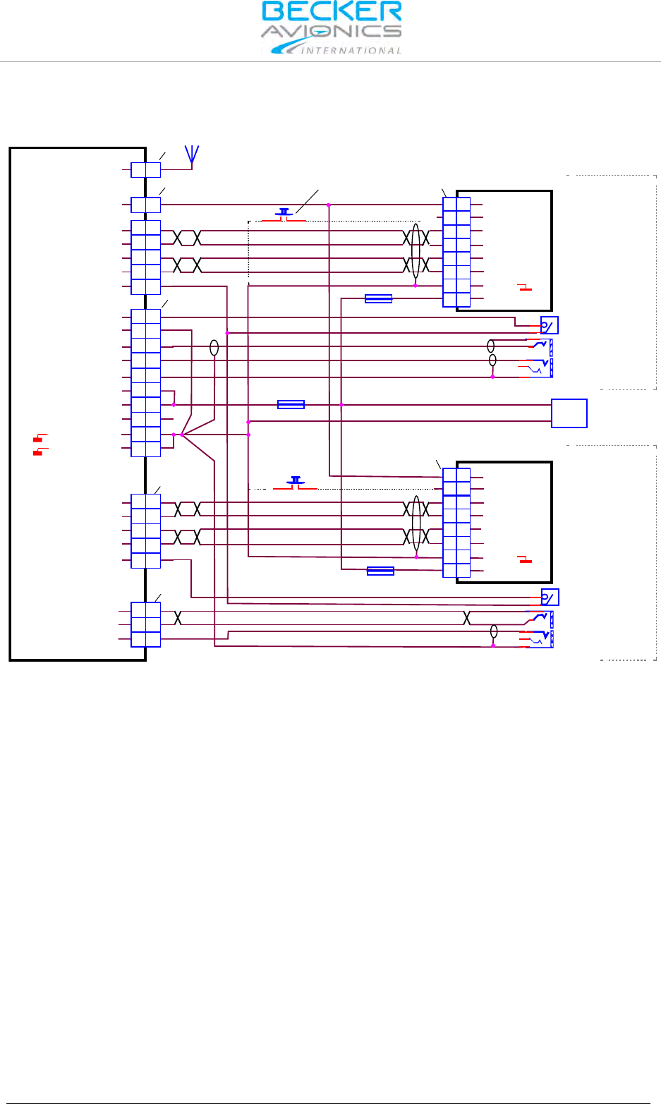
Installation
Wiring Diagrams and Settings
88 Transceiver Family 620X DV14307.03 Issue 04 March 2016
2.10.9.2. Wiring Diagram Twin Seat with RT6201 Tandem Configuration
ANTENNA
7.5 A
3 A
3 A
-
+
AWG20
AWG20 SUPPLY
14 V / 28 V
PTT
Frequency Exchange
(Remote Flip-Flop)
optional
Frequency Exchange
(Remote Flip-Flop)
optional
Earphone
PJ055
Standard Mike Pilot
PJ068
PTT
Earphone
PJ055
Standard Mike Pilot
PJ068
J3
J1
J1
P1
P1
P1
ANTENNA
/ON
RX2+
RX2-
TX2+
TX2-
RX1+
RX1-
TX1+
TX1-
D_GND
/EXT_ON
/EXCH_CH
TX0_422+
TX0_422-
RX0_422+
RX0_422-
GND
SUPP_IN
/EXT_ON
/EXCH_CH
TX0_422+
TX0_422-
RX0_422+
RX0_422-
GND
SUPP_IN
/PTT1
HDPH1_B
HDPH2_A
/PTT2
HDPH2_B
HDPH2_A
MIKE_STD1_HI
MIKE_STD2_HI
MIKE_STD_LO
P_SUPP
P_SUPP_GND
P_SUPP_GND
P_SUPP
/PWR_EVAL
A
A
24 24
12 12
11 11
13 13
25 25
25 25
23 23
10 10
14 14
77
17 17
3 3
3 3
2 2
2 2
5 5
18 18
88
88
9 9
9 9
20 20
15 15
22 22
RT6201-(X1X) / RT6201-(X2X)
13 13
15 15
1 1
2 2
4 4
5 5
9 9
11 11
RCU6201-(X1X)
13 13
15 15
1 1
2 2
4 4
5 5
9 9
11 11
RCU6201-(X1X)
P1
PRIMARY
SECONDARY
Figure 2-29: Wiring for Twin Seat with RT6201 Tandem Configuration
Note: Setup configuration only via Primary RCU
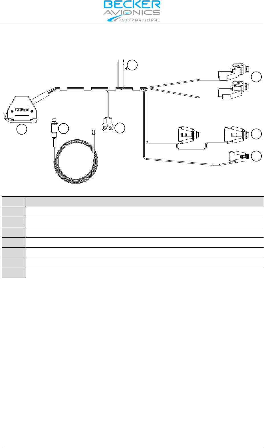
Installation
Predesigned Cable Harness
DV14307.03 Issue 04 March 2016 Transceiver Family 620X 89
2.11. Predesigned Cable Harness
2.11.1. 1K065 for General Aviation
7
6
5
4
3
2
1
Figure 2-30: Cable harness 1K065
Connector
1
Dsub connector (to P1 unit connector)
2
Connector for PTT switch (see 7)
3
Power supply lines
4
2x Microphone, jack socket PJ68
5
2x Phone, jack socket PJ55
6
Audio input, jack socket 3.5 mm
7
PTT switch
Order code see: "Accessories", page 30.
2.11.2. 1K062 (Open Cable Ends)
The cable harness 1K062 has open cable ends, the basic construction is like type 1K065.
2.12. Retrofitting AR4201 with AR6201
In most cases, a retrofit of the AR4201 with an AR6201 will not cause any problems.
However, in a few cases differences may occur due to pin incompatibility.
Connecting the AR6201 to an AR4201 wiring will NOT damage the AR6201 or the aircraft installation.
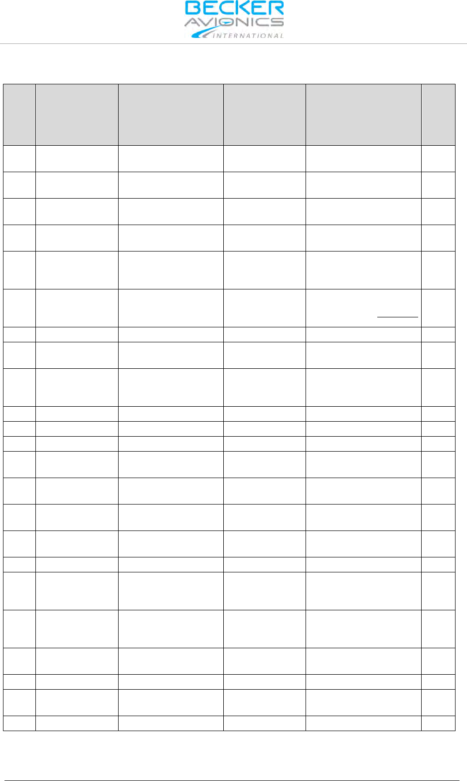
Installation
Retrofitting AR4201 with AR6201
90 Transceiver Family 620X DV14307.03 Issue 04 March 2016
2.12.1. Pin Compatibility AR4201 - AR6201
Pin
No.
AR4201
Pin Name
AR4201
Function
AR6201
Pin Name
AR6201
Function
Full
compatible
P1-1 AF-ASYM
Speaker output,
unbalanced SPK_HI
Speaker output,
unbalanced Yes
P1-2 AF-HI
Headphone output,
balanced HDPH1_A
Headphone 1 output,
balanced Yes
P1-3 AF-LO
Headphone output,
balanced HDPH1_B
Headphone 1 output,
balanced Yes
P1-4 AFAUX
Auxiliary audio input,
unbalanced AF_AUX_IN_HI
Auxiliary audio input,
unbalanced Yes
P1-5 MIKE DYN
Dynamic microphone
input, high side,
unbalanced
MIKE_DYN_HI
Dynamic microphone
input, high side,
balanced
Yes
P1-6 MIKE GROUND
Ground for dynamic
microphone,
unbalanced
MIKE_DYN_LO Dynamic microphone
input, low side, balanced No
P1-7
IC
Intercom input
IC
Intercom input
Yes
P1-8 TEMS1
Input for temperature
sensor MIKE_STD_LO Ground No
P1-9 RXD RS232-serial-data-line
MIKE_STD2_HI
Standard microphone 2
input, high side,
unbalanced
No
P1-10
-ILLUMINATION
Illumination, low side
ILL_LO
Illumination, low side
Yes
P1-11
+13.75 V
Positive power supply
P_SUPP
Positive power supply
Yes
P1-12
+13.75 V
Positive power supply
P_SUPP
Positive power supply
Yes
P1-13
GROUND
Power supply return /
Ground P_SUPP_GND
Power supply return /
Ground Yes
P1-14
AF GND
MIKE STD GND Ground SPK_LO Ground Yes
P1-15
AFCU
Normally not used in
installation LINE_OUT
Normally not used in
installation No
P1-16
AGC/AFWB
Normally not used in
installation AGC_OUT
Normally not used in
installation No
P1-17
PTT
Press to talk
/PTT
Press to talk
Yes
P1-18
MIKE STD1
Standard microphone
input, high side,
unbalanced
MIKE_STD1_HI
Standard microphone 1
input, high side,
unbalanced
Yes
P1-19
CODE PIN Used for identification
of the connection MIKE_STD3_HI
Standard microphone 3
input, high side,
unbalanced
No
P1-20
TEMS2 Headphone 2 HDPH2_A
Headphone 2 output,
balanced No
P1-21
GNDDATA
Ground
AF_AUX_IN_LO
no Ground
No
P1-22
TXD RS232-serial-data-line
HDPH2_B
Headphone 2 output,
balanced No
P1-23
ILLUMINATION
Illumination, high side
ILL_HI
Illumination, high side
Yes
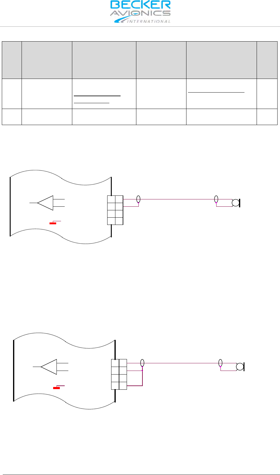
Installation
Retrofitting AR4201 with AR6201
DV14307.03 Issue 04 March 2016 Transceiver Family 620X 91
Pin
No.
AR4201
Pin Name
AR4201
Function
AR6201
Pin Name
AR6201
Function
Full
compatible
P1-24
+13.75V
SWITCHED
Power on monitor
Switched positive
power supply.
/PWR_EVAL
Power on monitor,
open collector output,
conducting to GND for
"On"
No
P1-25
GROUND
Power supply return /
Ground P_SUPP_GND
Power supply return /
Ground Yes
2.12.2. Dynamic Microphone Input
Retrofitting an AR4201 with the AR6201 in a typical glider installation with a dynamic microphone is
shown below:
Dy namic Mike
18
6
5
8
MIKE_STD_LO
MIKE_DYN_LO
MIKE_STD_HI
6
5
MIKE_DYN_HI
8
18
Figure 2-31: AR6201 with wiring interface for AR4201
Connect the cable shielding to pin P1-6, which is the low side input for dynamic microphone. Because
in AR6201 this input is balanced, the cable shield is no longer connected to ground (unlike it was with
the AR4201). In most cases, it is not a problem.
If interference with the microphone signal does occur, it is recommended to carry out the following
modification:
Connect Pin P1-6 with Pin P1-8 (the cable shield is grounded). See Figure.
Dy n a mic Mike
5
8
18
6
MIKE_STD_LO
MIKE_STD_HI
MIKE_DYN_LO
MIKE_DYN_HI 5
6
18
8
Figure 2-32: Modified dynamic microphone wiring interface for AR6201
2.12.3. Temperature Sensor
The AR6201 has no temperature sensor input. Remove wire from pin P1-8 and pin P1-20.
2.12.4. RS232 Interface
The AR6201 has no RS232 interface for remote control. Remove wire from pin P1-9 and pin P1-22.

Installation
Post Installation Tests
92 Transceiver Family 620X DV14307.03 Issue 04 March 2016
2.12.5. AFCU/AGC/AFWB
Not used in aircraft installations, remove pins P1-15 and pin P1-16.
2.12.6. CPIN (if Installed)
No influence in retrofit installation, please remove coding cap from the connector hole.
2.12.7. +13.75 V Switched (AR4201) - PWR_EVAL (AR6201)
The AR6201 provides on pin P1-24 a low signal when the unit is switched on and a high impedance
signal, when switched off.
Note: This is not compatible to the AR4201, which provided a positive power supply
when switched on and high impedance when switched off.
In cases where slave equipment needs to be switched ON/OFF in sync with the AR6201 connect a
relay to pin P1-24.
2.13. Post Installation Tests
Note: It is assumed that the "Configuration Setup" (see "Configuration Setup", page 53) has
been done before the Post Installation Tests will be carried out.
Once the 620X is installed, complete a test procedure to verify system functionality. Ensure
compliance with authority required procedures. Refer to the installation order of the minor change
document or use an own approved test protocol for VHF units. The following chapter provides
guidance for such tests.
2.13.1. Mechanical Installation and Wiring Check
• Verify all cables are fixed securely and shields connected properly to signal ground.
• Check the movement of aircraft controls to verify there is no interference.
• Verify all screws are tight and the connectors on the rear side of the unit are secured.
2.13.2. Power Supply
• Check the power supply lines and confirm correct polarity.
• Confirm that the aircraft power supply is within the specified limits, with and without a
running engine.
2.13.3. Receiver / Transmitter Operation
• Power up the 620X and tune it to a local station for a communication test.
• Verify that the receiver output produces a clear and readable audio and ask the local
station for proper readability for the transmit signal of the 620X.
• Repeat this communication test with an airborne station within ≈ 20-40 NM (Nautical
Miles).
2.13.4. Antenna Check
• Check the VSWR (voltage standing wave ratio) over the complete frequency band (e.g. by
using a VHF Reflection-Coefficient Meter).
The VSWR ratio should be less than 2:1 and is not acceptable when exceeding 3:1.
2.13.5. Interference Check
• Check the 620X while engine is running and all other avionics/ electrical systems on the
aircraft are powered, to verify that no significant interference exists.
• Check also that the 620X does not cause significant interference with other systems.
The installer´s standard test procedure may be used for the interference check and the table can be
taken as a reference. Depending on the individual avionic systems installed in the aircraft, it might be
necessary to extend the following checklist accordingly.

Installation
Post Installation Tests
DV14307.03 Issue 04 March 2016 Transceiver Family 620X 93
Aircraft System
Function
OK
NOT OK
DME
Audio
Generators / Inverters
GPS System
Compass 1
ADF
VHF / NAV1 all channels
VHF / NAV 2 all channels
Marker Beacon
Motor(s)
Engine Instruments
Stormscope
Transponder
Air Data Computer
Autopilot and Servos
• Power the GPS and make sure that not less than 5 satellites are tracked.
• Check the interference between the VHF-COM and the GPS receiver (when activated in
NAV mode).
• Select the following channels/frequencies on the 620X and on each frequency stay in TX
and RX mode for at least 30 seconds.
• Verify that GPS integrity flag is always out of view.

Installation
Post Installation Tests
94 Transceiver Family 620X DV14307.03 Issue 04 March 2016
Channel
Frequency (MHz)
121.140
121.1416
121.150
121.1500
121.155
121.1500
121.160
121.1583
121.165
121.1666
121.175
121.1750
121.180
121.1750
121.185
121.1833
121.190
121.1916
121.200
121.2000
121.205
121.2000
121.210
121.2083
131.240
131.2416
131.250
131.2500
131.255
131.2500
131.260
131.2583
131.265
131.2666
131.275
131.2750
131.280
131.2750
131.285
131.2833
131.290
131.2916
131.300
131.3000
131.305
131.3000
131.310
131.3083
For the remaining avionic equipment repeat all interference checks during a flight and include all
equipment not previously checked out on ground. A communication performance check in the low, mid
and high frequency band of the 620X should be included.
• Verify the receiver output produces a clear and understandable audio output.
• Verify the transmitter by contacting another station and getting a report of reliable
communications.
• Perform the range check with a station at least 100 m from your own position.
• Check the intercom function by talking into the microphone, while the engine is running at
cruising rpm. You should hear yourself and/or your co-pilot loud and clear.
• Switch "ON" the squelch and check that the normal radio noise, without a present carrier
signal, it will be constantly suppressed. The threshold of the squelch can be set in the
user menu.
2.13.6. Flight Test Check
It is highly recommended to perform flight test as final installation verification. The performance of the
620x may be verified by contacting a ground station at a range of at least 50 NM while maintaining an
appropriate altitude and over all normal flight attitudes.
• Check the performance in the low, mid and high band frequencies.

Installation
Trouble Shooting
DV14307.03 Issue 04 March 2016 Transceiver Family 620X 95
2.14. Trouble Shooting
Problem
Possible Reason
Proposed Solution
No Intercom function.
(You can’t hear yourself when
talking into the microphone).
VOX is switched "OFF", or
adjusted to a too high value.
Adjust the VOX to a lower value. A
value of
"-15" is suitable in most
cases.
Refer to "Configuration
Setup
", page 53).
The intercom volume adjusted to
a too low value.
Adjust the intercom volume to a
higher value. A value of
"37"
produces already a quite loud
intercom signal.
Refer to
" Configuration Setup",
page
53).
The sensitivity of the microphone
input is not sufficient. The level is
adjusted to a too high
value.
Adjust the sensitivity of the
microphone input to a lower value.
For most common avionic headsets
a setting of 50…120 mV is
sufficient.
Refer to
"Configuration Setup",
page
53).
VOX threshold is not adjustable.
VOX is always off.
VOX is inoperative, because
speaker is on.
Switch speaker to "OFF".
Refer to
"Configuration Setup",
page
53).
Too high cabin noise during
intercom / transmit operation.
The sensitivity of the microphone
input is too sensitive.
Adjust the microphone sensitivity to
a higher value to ensure the cabin
noise relatively reduces.
Recheck transmit
operation and/or
Intercom function.
Refer to
"Configuration Setup",
page
53).
No Speaker output.
Speaker is switched off
Switch Speaker "ON.
Refer to
"Configuration Setup",
page
53).
The noise suppression function
of the squelch is not working.
(Receiver noise is always
present).
Some avionic (especially non
ETSO/TSO approved avionic)
can produce quite high
electromagnetic interference,
which is receiving by the
AR6201
-().
Reduce the interference emitted by
the avionic around by improving
shielding, distance or grounding.
The interference may also been
suppressed by adjusting the
squelch to a higher value.
Refer to
"
Configuration Setup", page 53).
Note, that a higher value will cause
a reduced sensitivity.
Display shows Warning/Failure
message
.
(LOW BATT, STUCK PTT, TX
HOT, FAILURE)
Refer to "Warning and Failure
Indications
", page 113).

Installation
Continued Airworthiness
96 Transceiver Family 620X DV14307.03 Issue 04 March 2016
Problem
Possible Reason
Proposed Solution
Antenna VSWR exceeds 3:1.
Possibly caused by a defective,
or insufficient counterpoise for
the antenna.
Check for sufficient size of the
counterpoise and make sure there
is no mechanical defect on the
antenna.
The impedance of the antenna
cable deviates significantly from
50
Ω.
Make sure the used antenna cable
has 50 Ω impedance and the cable
is not bend or kinked on its way
from the radio to the antenna
Defective BNC connectors on the
antenna cable.
Check for proper crimp/solder work
on the BNC connectors and rectify
as far as necessary.
2.15. Continued Airworthiness
The 620X family maintenance is defined as "on condition" only. No scheduled or regular maintenance
of this product is required.
It is recommended to check the frequency accuracy of the airborne transceiver after 7 years.

Operating Instructions
Device Description
DV14307.03 Issue 04 March 2016 Transceiver Family 620X 97
3. Operating Instructions
In this chapter you can read about:
3.1. Device Description ...................................................................................................................... 97
3.1.1. Device Assignment ........................................................................................................... 97
3.1.2. Type Plate ......................................................................................................................... 97
3.2. Controls and Indicators ............................................................................................................... 99
3.3. Start-Up ..................................................................................................................................... 100
3.4. Receive and Transmit Mode ..................................................................................................... 100
3.4.1. Receive Mode ................................................................................................................. 100
3.4.2. Transmit Mode ................................................................................................................ 100
3.5. Frequency Selection Modes...................................................................................................... 101
3.5.1. Standard Mode ............................................................................................................... 101
3.5.2. Direct Tune Mode ........................................................................................................... 102
3.5.3. Channel Mode ................................................................................................................. 104
3.5.3.1. Select Channels .................................................................................................. 104
3.5.4. Frequency Storage Functions ......................................................................................... 105
3.5.4.1. Store .................................................................................................................... 105
3.5.5. Automatic Storage Function ........................................................................................... 106
3.5.5.1. Delete data: ......................................................................................................... 106
3.5.6. Scan Mode ...................................................................................................................... 107
3.6. SQUELCH ................................................................................................................................. 108
3.7. RX Field Strength Indication ..................................................................................................... 108
3.8. Channel Spacing Mode ............................................................................................................. 108
3.9. Auxiliary Audio Input ................................................................................................................. 109
3.10. Intercom Operation ................................................................................................................... 109
3.11. VOX & Speaker Operation ........................................................................................................ 110
3.12. Menus ........................................................................................................................................ 110
3.12.1. Intercom Menu ................................................................................................................ 110
3.12.2. User Menu ...................................................................................................................... 112
3.13. Warning and Failure Indications ............................................................................................... 113
The chapter "Operating Instructions" in this manual contains general information and instructions to
ensure safe operation of the VHF transceivers.
3.1. Device Description
In this section the figures for illustrating display content mainly show
transceivers working in 8.33/25 kHz mixed mode. Dedicated pictures for
25 kHz mode are not explicitly shown (they differ only in number of digits
for frequency).
The HMI actions described in this section can be performed on primary
controller or on optional secondary controller RCU6201.
The following graphics of the display content show the 8.33 kHz channel
spacing for all possible operation modes.
3.1.1. Device Assignment
• See page 33
3.1.2. Type Plate
• See page 35
•
Switch OFF the device before starting or shutting down engines.

Operating Instructions
Device Description
98 Transceiver Family 620X DV14307.03 Issue 04 March 2016
A voice communication test shall be performed before starting
the engine.
It should be noted that, if the communication test is carried out
close to a ground station, the results may be positive even if the
antenna cable is broken or short-circuited. In such a case, at a
distance of 5 to 10 km and above, communication might not be
possible.
• Speak always loud, clear and not too fast for optimal voice communication.
• Keep the microphone always close to the lips otherwise a special suppressing circuit in
the VHF COM will not be capable to suppress normal cabin noise.
• Use only microphones or headsets which are suitable for use in an aircraft.
o In aircraft made of wood, synthetic materials or in gliders or helicopters, incoming
radiation can affect the integrated amplifier of the microphone (feedback), noticeable in
the ground station by whistling and/or heavy distortion.
If the power supply voltage drops below the "Low Battery Threshold" (default value is 10.5 V), the
"LOW BATTERY" message will appear each 3 seconds in the lower part of the display.
If the power supply voltage drops below 10 V the system enters
power saving mode:
• Speaker output of the transceiver is automatically
switched "OFF"
• Speaker sign will no longer be presented on LCD
display
• The pilot must use headphones to continue listening.

Operating Instructions
Controls and Indicators
DV14307.03 Issue 04 March 2016 Transceiver Family 620X 99
3.2. Controls and Indicators
AR620X and RCU6201
AR6203
Figure 3-1: Controls and indicators
Symbol
Description
Main Function
1
IC/SQL
(Intercom/Squelch)
"Short press" during normal operation toggles the RX -SQL ON/OFF.
"Long press" during normal operation activates Intercom Menu.
2
MDE
(Mode)
"Short press" during normal operation changes the frequency selection
mode.
"Long press" during normal operation activates the user menu.
3
STO
(Store)
"Short press" during normal operation activates storage procedure.
4
↨/SCN
(Exchange/SCAN)
"Short press" during standard mode, or scan mode toggles between
preset and active frequency.
"Long press" activates scan mode.
5
Power ON/OFF,
Volume Knob
Switches the transceiver ON/OFF and adjusts volume level of received
signal.
6
Rotary encoder
Turning "ROTARY ENCODER" changes the settings of several
parameters (frequency, IC-volume, VOX, …).
Pushing the "ROTARY ENCODER" toggles between the digits and acts
as an enter key.
-8/25-
Change of
Channel Spacing
Keeping the MOD and STO button pressed simultaneously longer than
2 seconds changes 8.33 to 25 kHz channel spacing and vice versa.
7
Display
LCD: Liquid Crystal Display
8
Active frequency
Only on the active frequency, transmitting is possible and receiving has
priority, even in scan mode. Frequency tuning is not possible in standard
mode.
9
Preset frequency
Frequency tuning is possible in standard mode. In scan mode both
frequencies, active and preset are in listening watch. If no receive signal
is detected on the active frequency, receiving signals on the preset
frequency will be audible, but will be muted as soon as a signal on the
active frequency is detected.
The device detects a:
"Long press": when pressing and holding down a key for at least 2 seconds.
"Short press": any pressing below 2 seconds.

Operating Instructions
Start-Up
100 Transceiver Family 620X DV14307.03 Issue 04 March 2016
If any action by the user is invalid, the whole display inverting for a short time.
Symbols shown on the Display
Symbol
Function
IC
Intercom operation is active (triggered by VOX or external IC key)
Intercom operation via VOX is disabled
TX
The transceiver is in transmit operation
SQL
The squelch function is active, weak RX signals suppressed.
SCAN
Transceiver operates in scan mode
STO
The transceiver performs a storage operation.
LOW BATT
Battery below predefined low threshold
128.225
Inverted figures or letters on display ready to edit
Speaker on
3.3. Start-Up
Excessive pulses on the DC bus of the aircraft may cause damage on
electrical circuits of any installed instrument.
Do not switch ON the device during engine start or shutdown
• Turn "ON" the device by turning the volume knob clockwise.
• During PBIT (Power-On Built In Test) the display indicates the message "WAIT", the
software version of "Control Head" (CH) and the software version of "Core Module" (CM).
• If the PBIT has detected error(s),"FAILURE" appears on the display (for details see
chapter 3.13).
3.4. Receive and Transmit Mode
3.4.1. Receive Mode
If /PTT1 and /PTT2 (Push To Talk) inputs are inactive, the transceiver remains in receive mode.
In receive mode the headphone(s) outputs (if enabled) provide a mixed signal consisting of:
• Received signal from antenna,
• Intercom signal from intercom circuit one and two,
• Signal from auxiliary input.
In receive mode the speaker output (if enabled) provides a mixed signal consisting of:
• Received signal from antenna
• Signal from auxiliary input
The signal from the auxiliary input been muted under certain conditions (For details refer to "Intercom
Operation", page 109).
The signal from intercom can be attenuated, or muted, under certain conditions (For details refer to
"VOX & Speaker Operation", page 110).
3.4.2. Transmit Mode
If /PTT input is active (PTT=Push To Talk key is pressed) the transceiver switches to transmit mode.
Microphone(s) signals can modulate the transmitter.
• PTT 1 input activates transmission from microphone path 1
• PTT 2 input activates transmission from microphone path 2
• If BOTH MIKES are active / enabled in the configuration setup, each input (PTT 1 or 2)
activates the transmission from both microphone paths simultaneously.
The "TX" symbol in the left upper corner of the display indicates the device is in transmit mode.

Operating Instructions
Frequency Selection Modes
DV14307.03 Issue 04 March 2016 Transceiver Family 620X 101
118.005
127.000
TX
In transmit mode several user actions such as changing frequency selection mode or channel spacing
mode, which are normally allowed in receive mode, are blocked. (As an exception in standard mode
the "Preset" frequency may still be changeable, even during transmission).
No intercom operation is possible in transmit mode.
The sidetone (demodulated audio of the emitted signal) is available on the headphone output. The
transmit mode automatically deactivates the speaker.
Note: Transmit mode is automatically terminated (return to receive mode) after
120 seconds of continuous transmitting even if PTT is still pressed. In this case
"STUCK PTT" is indicated (refer to page 113). For initiation of a new
transmission, /PTT line needs first to become inactive.
3.5. Frequency Selection Modes
Following frequency selection modes are available on AR620X and RCU6201:
• Standard mode
• Direct tune mode
• Channel mode
• Scan mode
The "Standard Mode", "Direct Tune Mode" and "Channel Mode" provide different user interfaces for
convenient selection of the operating frequency. These three frequency selection modes are
selectable by consecutive short pressing of "MDE" key.
They appear in the following order: "Standard Mode", "Direct Tune Mode" "Channel Mode",
"Standard Mode", and so on. When toggling between the three modes the active frequency always
remains the same and active.
"SCAN Mode" is a sub-mode of standard mode and used for monitoring two frequencies at the same
time. A 2 seconds press on "↕/SCN" key activates/deactivates the scan function.
The availability of the modes depends on enabling or disabling in the "Configuration Settings".
3.5.1. Standard Mode
Press the "MDE" key until the standard mode page appears.
The standard mode page displays the active frequency in the top line and preset frequency in the
bottom line.
118.005
127.000
IC
SQL
Changing the active frequency is not possible in standard mode (only available in direct tune mode)
but changing the preset frequency is possible.

Operating Instructions
Frequency Selection Modes
102 Transceiver Family 620X DV14307.03 Issue 04 March 2016
Changing the preset frequency in standard mode:
• Make a "short press" on the "ROTARY ENCODER" for modification of the 100 MHz digits.
Rotate the "ROTARY ENCODER" clockwise/counter clockwise to change the frequency in
1 MHz steps.
118.005
128.000
SQL
• Make another "short press" on the "ROTARY ENCODER" for modification of the 100 kHz
digits.
Rotate the "ROTARY ENCODER" clockwise/counter clockwise to change the frequency in
100 kHz steps.
118.005
128.000
SQL
• Make another "short press" on the "ROTARY ENCODER" for modification of the
25/8.33 kHz digits.
Rotate the "ROTARY ENCODER" clockwise/counter clockwise to change the frequency in
25/8.33 kHz steps.
128.000
SQL
118.005
A short press of the "↨/SCN" key, exchanges active frequency to preset frequency and vice versa.
If wanted, please press now the "STO" key to store the active frequency into the next vacant memory
place of the user channels database.
Note: While the transceiver operates in transmit mode, the toggle function is disabled.
3.5.2. Direct Tune Mode
Press the "MDE" key until the direct tune mode page appears.
IC
SQL
118.005
BAT 13.5V
Note: The battery information is only displayed if BATTERY VOLTAGE in the
configuration setup is selected.
In direct tune mode, the active frequency appears in the top line. It can be edited by means of the
"ROTARY ENCODER" following the procedure.
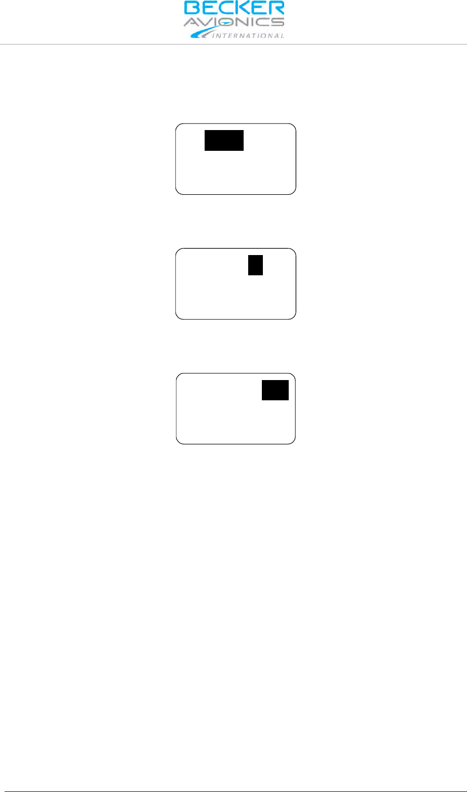
Operating Instructions
Frequency Selection Modes
DV14307.03 Issue 04 March 2016 Transceiver Family 620X 103
Changing the active frequency when in direct tune mode:
• Make a "short press" on the "ROTARY ENCODER" for modification of the 100 MHz digits.
Rotate the "ROTARY ENCODER" clockwise/counter clockwise to change the frequency in
1 MHz steps.
IC
SQL
118.005
• Make another "short press" on the "ROTARY ENCODER" for modification of the 100 kHz
digits.
Rotate the "ROTARY ENCODER" clockwise/counter clockwise to change the frequency in
100 kHz steps.
IC
SQL
118.005
• Make another "short press" on the "ROTARY ENCODER" for modification of the
25/8.33 kHz digits.
Rotate the "ROTARY ENCODER" clockwise/counter clockwise to change the frequency in
25/8.33 kHz steps.
IC
SQL
118.005
Notes:
The changes become active immediately
Changing the active frequency is possible only when the transceiver is not transmitting.
If wanted, please press now the "STO" key to store the active frequency into the next vacant memory
place of the user channels database.

Operating Instructions
Frequency Selection Modes
104 Transceiver Family 620X DV14307.03 Issue 04 March 2016
3.5.3. Channel Mode
The channel mode shows data from User Channels Database (indicated by "CH"), or Last Channels
Database (indicated by "LAST") and shows if applied a customized label (identifier) for the frequency
(max. 10 characters).
The channel database provides storage of:
• CH01 to CH99 and
• LAST 1 to LAST 9.
Note The functions "LAST" and Store/Restore are only available if this options are
activated in "Configuration Settings" - "MEM OPTIONS".
Note: If the device is operating in the 25 kHz mode a selection of an earlier stored
8.33 kHz channel is not possible. For selection of 8.33 kHz channels, the device
must operate in 8.33 + 25 kHz mixed mode.
Press the "MDE" key the channel mode page appears.
By means of channel number stored frequencies can be selected. The top line shows the
corresponding frequency and the bottom line the customized label (identifier) assigned to the
frequency number.
If the active frequency has no assigned channel number the indication is "CH--".
IC
SQL
125.875
CH
TWR EDSB 01
IC
SQL
125.875
LAST
TWR EDSB 1
3.5.3.1. Select Channels
Example: With CH01 user channel shown on display:
In order to select the channel number:
• The first turn clockwise in channel mode provides navigation up user channels CH01 to
CH99.
o Make a short press of the "ROTARY ENCODER", or:
o Make one clockwise turn of the "ROTARY ENCODER".
The channel number is now highlighted and the channel can be changed turning the "ROTARY
ENCODER". At each step the receiver tunes immediately to the displayed frequency.
• The first turn counter-clockwise will enter to the channel "LAST 1.
o The channel number is now highlighted and one of the nine last used channels is
selectable by turning the "ROTARY ENCODER" either counter clockwise or
clockwise.
The "LAST" mode is left automatically after a 5 second timeout or can be deselected by repeated
pressing of the "ROTARY ENCODER".
When leaving the "LAST" channel database and the last shown frequency is not stored in the User
channel database, "CH__" appear on the display. Press "STO" to start the storage process.
Leave Channel Mode:
Press the "MDE" key the standard page appears.

Operating Instructions
Frequency Selection Modes
DV14307.03 Issue 04 March 2016 Transceiver Family 620X 105
3.5.4. Frequency Storage Functions
Start store function by pressing:
• "STO" key in "Standard Mode", "Direct Tune Mode" and "SCAN Mode".
During this procedure, the display looks similar to the channel mode with one difference
that "STO" appears on the left side of the display.
3.5.4.1. Store
The transceiver provides two databases:
• User channels database - provides 99 channels CH01 to CH99 to store frequencies with
the possibility to apply a customized label (identifier) with max. 10 alphanumeric
characters.
• Last channels database - automatically stores 9 last used frequencies with customized
identifier if applied, easy to recall as LAST 1 to LAST 9.
Any frequency can be assigned to any channel within the range from 118.000...136.9916 MHz by
simply pressing the "STO" button. All 99 channels are editable. By entering the storage procedure, the
device will first propose the next free channel for storing the active frequency. The label "FREE"
appears together with the channel number, if the selected channel is vacant. A selected channel with
an already stored frequency, has the label "USED".
If the same frequency is stored a second time, then the existing data (frequency, label/identifier data)
is offered to store. If the frequency has no label attached, ten underscore digits allows to insert a label.
The cursor automatically appears on the first position.
The data can be stored to:
• Next free channel (offered from system).
• A selected free channel.
• A selected used channel (the existing data will be replaced).
STO CH
FREE 09
125.875
STO 09
CH
USED
125.875
STO
_ _ _ _ _ _ _ _ _ _
125.875
STO
TWR EDSB _ _
125.875
Label (Identifier) Data:
By turning the "ROTARY ENCODER" characters can be selected. Selection works in both directions
(example: A...Z0...9—/blankA" by turning clockwise and vice versa by turning
counter clockwise).
Each "short press" on the "ROTARY ENCODER", the cursor is passed to the next position. A short
press of the "STO" key stores the label a long press of the "STO" key clears the currently edited label.
After storing the transceiver returns back to the previous frequency selection mode.
If no action occurs in label editing mode within 7 seconds, the transceiver returns to the previous
frequency selection mode without storing the frequency and label information.
Stored frequencies are recallable in Channel Mode (see "Channel Mode" page 104).

Operating Instructions
Frequency Selection Modes
106 Transceiver Family 620X DV14307.03 Issue 04 March 2016
3.5.5. Automatic Storage Function
The transceiver stores 9 recently selected frequencies and updates the last channels database during
operation in "Standard Mode", "Direct Tune Mode" and "Scan Mode".
When changing to a new active frequency, the previous active frequency is stored "LAST" in memory
LAST 1. The frequencies previously located in LAST 1…LAST 8 are shifted to memory channels
LAST 2…LAST 9. This algorithm ensures the last 9 used active frequencies are available. Last used
frequencies "LAST" can be recalled in channel mode (see "Channel Mode" page 104).
Note The function "LAST" and Store/Restore to channels are only available if this options are
activated in "Configuration Settings" - "MEM OPTIONS".
3.5.5.1. Delete data:
The stored content in User Channel Database can only be deleted in "Configuration Settings". Please
note the whole channel database will be reset.

Operating Instructions
SQUELCH
DV14307.03 Issue 04 March 2016 Transceiver Family 620X 107
3.5.6. Scan Mode
In Scan Mode the display shows both the active frequency on the top line and the preset frequency on
the bottom line. The SCAN sign in the display indicates that scan function is active.
118.005
127.000
SQL
SCAN
In all frequency selection modes;
• A long press of "↕/SCN" key activates the scan function and changes to STANDARD
MODE if activated from CHANNEL or DIRECT TUNE mode.
• A short press on the "MDE" key or a long press on "SCN" key terminates scan function.
After leaving scan function, the device will remain in standard mode.
The arrow sign "►" in front of the active frequency indicates that this frequency is audible.
If both the active frequency and preset frequency simultaneously detect a signal, the active frequency
(top) takes priority. The preset frequency then inverts and blinks.
127.000
118.005
SQL
SCAN
If selected in the configuration setup an audio notification "beep" tone becomes audible in addition to
the blinking preset frequency to indicate the presence of an RX signal on the preset frequency.
Reception on Preset Frequency in Scan Mode
If the preset frequency detects a signal while no signal is present on the active frequency, the
transceiver automatically switches over to the preset frequency.
The arrow sign now appears in front of the preset frequency and the signal is audible.
127.000
118.005
SQL
SCAN
Note: Transmission always uses the active frequency, even if the monitored
frequency is currently audible.
If TX on the preset frequency is required, push the "↨/SCN" key to swap active
and preset frequency.
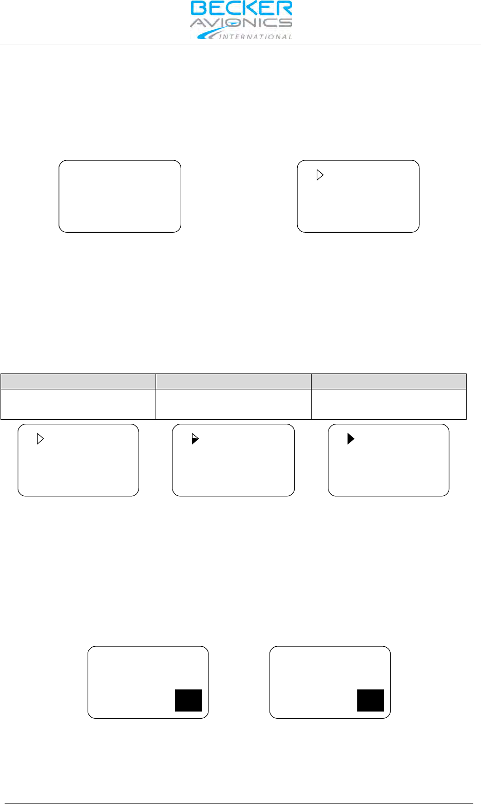
Operating Instructions
SQUELCH
108 Transceiver Family 620X DV14307.03 Issue 04 March 2016
3.6. SQUELCH
Independent of the selected operation menu, squelch can be toggled "ON" or "OFF" by a short press
on "SQL/IC" key.
• If the squelch function is active ("ON") the receivers noise is muted.
• If the squelch is "OFF" the arrow sign "►" in front of the active frequency stay visible all
the time and receiver noise will be audible as long as signal is receiving.
127.000
118.005
SQL
127.000
118.005
SQL
Squelch "ON"
Squelch "OFF"
In the user menu, the squelch threshold is adjustable to a convenient trigger level. See "User Menu"
page 112.
3.7. RX Field Strength Indication
The field strength indicator, represented by triangle on the left upper corner of the corresponding
frequency, will appear next to the active or preset frequency in all frequency selection modes.
The field strength of an incoming signal relates to the measured RSSI level. The three levels displayed
are:
Weak Signal Strength
Good Signal Strength
Excellent Signal Strength
RSSI passing squelch levels
(empty triangle)
-88 > RSSI > -80 dBm
(half-filled triangle)
RSSI > -80 dBm
(fully filled triangle)
127.000
118.005
SQL
127.000
118.005
SQL
127.000
118.005
SQL
3.8. Channel Spacing Mode
The transceiver provides two operation modes of frequency channel spacing, (8.33 and 25 kHz),
selectable by means of pressing "STO" and "MDE" keys simultaneously for at least 2 seconds.
In 25 kHz mode, 5 frequency digits are shown. Only operating frequencies with a channel spacing of
25 kHz are selectable. If 8.33 kHz channels are not in use, this mode provides the advantage of faster
tuning since skipping the 8.33 kHz frequency steps.
In 8.33 kHz and 25 kHz mixed mode 6 frequency digits are shown. The transceiver tunes to all
possible frequencies within the aviation VHF frequency band. The channel spacing and operating
frequency is derived automatically from the selected and displayed frequency.
127.000
118.000
SQL
127.00
118.00
SQL
8.33 kHz channel spacing (left) / 25 kHz channel spacing (right)
Toggling between the frequency channel spacing modes is only available for AR-, RCU620X-(0XX)
variants. The AR-, RCU620X-(1XX) variants provide operation in 25 kHz Mode only.

Operating Instructions
Auxiliary Audio Input
DV14307.03 Issue 04 March 2016 Transceiver Family 620X 109
3.9. Auxiliary Audio Input
The transceiver has a dedicated auxiliary audio input e.g. for MP3 player connection.
With auxiliary input enabled in configuration setup, the auxiliary audio input signal mixing with the
received signal from antenna (passing squelch) and the intercom signal (when activated).
When intercom operates in ISOLATION mode, auxiliary audio input signal is audible on headphone
2 output, even if radio communication (transmission/receiving) is active.
AUX AUTO MUTE function depends on the AUX INPUT, selectable via the CONFIGURATION page in
the configuration setup. This function automatically mutes the audio signal from the auxiliary audio
input as long as the AR620X detects (based on squelch evaluation) a RX signal or the user
deactivates the squelch manually. If this function is disabled the signal from the auxiliary audio input is
permanently audible on the audio output, independently of the received signal or the squelch status.
Automatic aux attenuation functionality controls the auxiliary audio input. The level of the auxiliary
input signal attenuates if intercom is activated by VOX or by /IC discrete input. The auxiliary input
signal reverts to its previous value after intercom deactivation. The attenuation value can be adjusted
within the range from 0...40 dB.
3.10. Intercom Operation
Intercom operation may be triggered automatically via VOX (with adjustable threshold) or externally
via intercom switch.
The setting of VOX-threshold and intercom volume is accessible in the intercom menu, in tandem
configuration on primary controller only.
For a single block, the primary controller is the one directly connected to VHF transmitter. For a
remote VHF transmitter the primary controller is the one connected to primary control interface.
VOX-threshold and intercom volume for the second intercom circuit are controllable from secondary
controller RCU6201 (secondary controller is the one connected to secondary control interface).
The transceiver has two internal built in intercom circuits. Therefore, up to four headsets are
connectable. Pilot and co-pilot connect to the first intercom circuit. When intercom is active, both
microphone signals are mixed and amplified with each other and will be audible on both headphone
outputs. This enables internal communication via headsets between both pilots. Passenger headsets
are connecting to the second intercom circuit.
ALL mode - Everyone connected to the intercom will hear all communications (pilots hear passengers
and passengers hear pilots).
ISOL mode - Provides separate intercoms for the pilots (intercom circuit one) and the passengers
(intercom circuit two). This allows pilots to communicate with each other, and air traffic, while the
passengers are isolated. The passengers on the intercom circuit two can hear auxiliary audio (for
example from mp3 player) and can communicate with each other.
External "ISOL" input provides possibility to switch between ALL mode and ISOL mode. If the /PTT1
input is active and ISOL is active the passenger intercom operation on second intercom circuit is still
possible.
While transmit mode intercom operation is degraded. During receive mode the intercom operation
activates automatically via VOX (with adjustable threshold), or using the external intercom switch.
If intercom operation is active, the "IC" sign appears in the display.
118.005
127.000
IC
SQL
Intercom Operation via VOX
Via VOX, the intercom operation is automatically activated (threshold adjustable in the intercom
menu). With additional RCU6201, VOX threshold for the first intercom circuit is adjustable from
primary controller (AR620X or RCU6201) and for the second intercom circuit from second controller
RCU6201.
Intercom activation via VOX is not possible if:
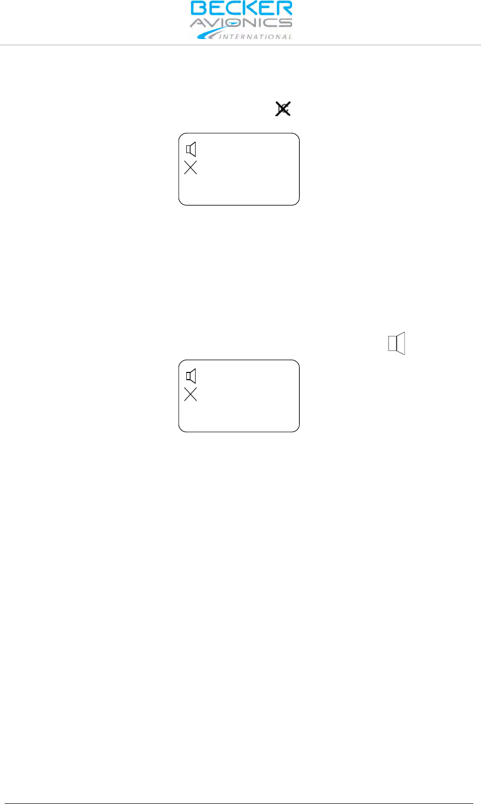
Operating Instructions
VOX & Speaker Operation
110 Transceiver Family 620X DV14307.03 Issue 04 March 2016
• It is enabled
• User switched the VOX off
In both cases, VOX is disabled and the display shows the sign to indicate that activation via VOX
is not possible.
118.005
127.000
IC
SQL
Intercom Operation via Intercom Switch
Via intercom switch (pin P1-7) independent of VOX or speaker status (enabled/disabled) the intercom
operation can be activated externally. The external intercom switch has priority. During intercom
operation the speaker output is disabled.
3.11. VOX & Speaker Operation
Depending on wiring and configuration setup, the speaker may either always been enabled, or the
speaker can be enabled/disabled by switching configurations using external switch /MIKE_SW.
When speaker enabled and not muted, the display will show the loudspeaker sign.
118.005
127.000
IC
SQL
With active enabled speaker in audio configuration, VOX always forced "OFF" and intercom via VOX
is not possible (to avoid oscillation of VOX due to acoustical feedback).
In transmission mode the speaker output is muted (switched "OFF") even if speaker is enabled in
current audio configuration in one of the following cases:
• Intercom is activated by external intercom switch (I/C input).
• Power is below 10 V.
3.12. Menus
During normal operation in one of the frequency selection modes, the following menus are available:
• The Intercom menu allows adjustment of intercom volume and VOX threshold.
• The user menu allows adjustment of panel brightness and squelch threshold.
3.12.1. Intercom Menu
A long press (2 s) on "IC/SQL" key activates the intercom menu.The page intercom volume appears.
In this menu a short press on "IC/SQL" key provides toggling between the pages.
The intercom menu consists of two pages:
• IC VOLUME,
• IC VOX.
A long press on "MDE" key terminates intercom menu, otherwise the menu automatically terminates
after 5 seconds timeout.

Operating Instructions
Menus
DV14307.03 Issue 04 March 2016 Transceiver Family 620X 111
Intercom Volume Menu
The active frequency is indicated in the top line of the display, the "IC VOLUME" label and a bar graph
with numerical value are show in the bottom line.
IC VOLUME
40
IC 118.005
By means of the "ROTARY ENCODER", the intercom volume is changeable from zero to 46. The
intercom volume setting affects the intercom audio and sidetone signal, routed to the headphone.
The changes become active immediately.
Intercom VOX Menu
The active frequency is indicated in the top line of the display, the "IC VOX" label and a bar graph with
numerical value are shown in the bottom line.
IC VOX
6
IC 118.005
By means of the "ROTARY ENCODER" the intercom VOX threshold can be changed from -30 (most
sensitive, even a very low microphone signal already triggers the VOX threshold for Intercom
operation) to +10 (VOX is less sensitive and only high microphone signals trigger the VOX threshold
for intercom operation).
Note: At a setting for VOX threshold of -15 a convenient behaviour of the VOX should
be achieved in most aircraft. This requires that mike sensitivity had been correct
adjusted (configuration setup). If the mike sensitivity is incorrect adjusted, VOX
may not work satisfying.
By changing VOX threshold level to above +10, VOX switches "OFF". In this case, "OFF" replaces the
numerical value indication.
The changes become active immediately.
IC VOX
OFF
IC 118.005
With VOX switched "OFF", activation of intercom operation using the external intercom switch (/IC
discrete input) is still possible at any time. The VOX threshold level is not adjustable if VOX forced to
be "OFF" (due to enabled speaker in current audio configuration).
In tandem installation the "first" controller adjust VOX threshold for first intercom circuit, and the
second controller RCU6201 adjust VOX threshold for second intercom circuit.

Operating Instructions
Menus
112 Transceiver Family 620X DV14307.03 Issue 04 March 2016
3.12.2. User Menu
Press the "MDE" key for 2 seconds to start the user menu. Toggling between the pages by a short
press of the "MDE" key, or by a short press of the "ROTARY ENCODER".
The user menu consists of two pages:
• BRIGHTNESS
• SQUELCH TRH
To exit the user menu either
• Wait 5 seconds without any switch selections.
• Press the "MDE" key again for 2 second,
• Press the "ROTARY ENCODER" when the SQUELCH setting page is visible,
BRIGHTNESS
The active frequency appears in the top line of the display "BRIGHTNESS" label appears in
combination with a bar graph and the selected value.
BRIGHTNESS
96
IC 118.005
The panel brightness for display illumination and push buttons can be changed from 0 (illumination off)
to 100 (maximum brightness) by turning the "ROTARY ENCODER".
Note: This page is not available if in configuration setup the dimming input is set to
14 V or 28 V. For this setting, the aircraft dimming circuit controls the
brightness parameters.
SQUELCH
A short press on the "ROTARY ENCODER" provides "SQUELCH" trigger level adjustment. The active
frequency appears in the top line of the display. On the bottom line "SQUELCH" with bar graph and
value is indicated.
SQUELCH
10
IC
118.005
By means of the "ROTARY ENCODER", the squelch threshold is adjustable:
• At a setting to 6 (very weak signals are audible with high noise content; squelch opens at
about -105 dBm).
• At a setting to 26 (only quite strong signals are audible with low noise content; squelch
opens at about -87 dBm). With this adjustment the receiver sensitivity is significant
reduced.
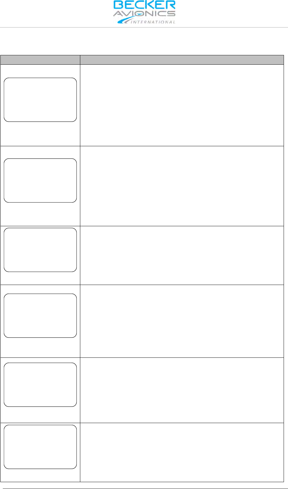
Operating Instructions
Warning and Failure Indications
DV14307.03 Issue 04 March 2016 Transceiver Family 620X 113
3.13. Warning and Failure Indications
Display Contents
Description
LOW BATTERY
IC
118.005
Appear in 3-second cycle
"LOW BATT" is indicated if the supply voltage of the transceiver is
below the threshold defined in the configuration setup.
The transceiver is still operable but may have a reduced performance
depending on supply voltage.
Possible reasons for indication:
Accumulator capacity problems (gliders),
Power interrupts,
General power supply problems,
Setting for low battery threshold too high
STUCK PTT
IC 118.005
Appear in 3-second cycle
"STUCK PTT" is indicated after 120 seconds of continued
transmission. The transceiver goes back to receive mode even if the
PTT line is still active (GND).
For initiating a new transmission, the PTT line needs first to become
inactive (open).
Possible reasons for indication:
Transmission lasts more than 120 seconds.
PTT-key is stuck.
PTT line permanently grounded (short circuit in installation).
TX HOT
IC 118.005
Appear in 3-second cycle
"TX HOT" is indicated if the internal device temperature exceeds
+90 °C.
Transceiver is still operable. Performance of transmitter is reduced.
Possible reasons for indication:
Very hot environmental temperature, long transmissions times and
insufficient airflow conditions.
FAILURE
IC 118.005
Appear in 3-second cycle
The transceiver has detected an internal failure during normal
operation.
Depending on failure reason, the device may still be operable with
degraded performance, or not operable at all.
Possible reasons for indication:
Specified environmental conditions
HW or SW failure inside the transceiver.
Contact maintenance shop for assistance.
FAILURE
PRESS ANY KEY
The transceiver has detected an internal failure during start up.
Depending on failure reason, the device may be still operable with
degraded performance or not operable at all.
Possible reasons for indication:
Outside specified environmental conditions
HW or SW failure inside the transceiver.
Contact maintenance shop for assistance.
FAILURE
The transceiver has no communication with the controller.
Depending on failure reason, the device may be still operable with
degraded performance or not operable at all.
Possible reasons for indication:
Problem with inter-wiring
Contact maintenance shop for assistance.

Operating Instructions
Warning and Failure Indications
114 Transceiver Family 620X DV14307.03 Issue 04 March 2016
In case of additional questions contact your local Becker Avionics dealer or forward your request direct
to Becker Avionics "Customer Service”.
In the event of damage or a defect, the entire device must be returned for repair. The repair must be
made by trained Becker Avionics personnel.
Becker Avionics GmbH • Baden-Airpark B108 • 77836 Rheinmünster • Germany
+49 (0) 7229 / 305-0 • Fax +49 (0) 7229 / 305-217
Customer Service:
Sales
Email: sales@becker-avionics.com
Support in German or English
Email: support@becker-avionics.com
Support in French
E-Mail: FR-sales@becker-avionics.com
User Conversions and Changes are Not Permitted
Any change made by the user excludes any liability on our part (excluding the work described in this
manual).

Operating Instructions
Warning and Failure Indications
DV14307.03 Issue 04 March 2016 Transceiver Family 620X 115

Index
116 Transceiver Family 620X DV14307.03 Issue 04 March 2016
4. Index
Abbreviations .......................................................... 7
Accessories ........................................................... 30
Activation of Intercom Operation via Intercom
Switch.................................................................. 110
Activation of Intercom Operation via VOX ........... 109
Additional Conditions of Utilization .......................... 9
AF Auxiliary Input .................................................. 19
ALL Mode ............................................................ 109
Antenna Installation ............................................... 53
AR6201 Single Block Transceiver ......................... 16
AR6203 Single Block Transceiver ......................... 18
Audio Outputs ....................................................... 19
Automatic Storage Function ................................ 106
Auxiliary Audio Input ........................................... 109
BRIGHTNESS ..................................................... 112
Built-in Tests PBIT and CBIT ................................ 20
CBIT ...................................................................... 20
Channel Mode ..................................................... 104
Conditions of Utilization ........................................... 9
Controls and Indicators ......................................... 99
Device Assignment ......................................... 34, 97
Direct Tune Mode ................................................ 102
Electrical Interface ................................................. 44
Emergency Operation ........................................... 20
Environmental Qualification AR620X, RCU6201 ... 24
Environmental Qualification RT6201 ..................... 26
Factory Default Settings ........................................ 68
Features Overview ................................................ 18
Frequency Selection Modes ................................ 101
General Description .............................................. 11
General Safety Definitions ....................................... 8
Illumination ............................................................ 20
Installation ............................................................. 33
Installation and Configuration ................................ 52
Configuration Setup ........................................ 20, 53
Intercom Menu .................................................... 110
Intercom Operation ....................................... 19, 109
Intercom Volume Menu ....................................... 111
Intercom VOX Menu ............................................ 111
ISOL Mode .......................................................... 109
List of Abbreviations ................................................ 7
LOW BATT Indication ........................................... 20
Memory Channels ................................................. 19
Menus ................................................................. 110
Mike Inputs ............................................................ 19
Non Warranty Clause .............................................. 9
Operation Instructions ........................................... 97
Packaging, Transport, Storage ............................. 33
PBIT ...................................................................... 20
User Menu .......................................................... 112
Post Installation Tests ........................................... 92
Purpose of Equipment ........................................... 13
RCU6201 Remote Control Unit ............................. 17
Receive and Transmit Mode ............................... 100
Receive Mode ..................................................... 100
Reception on Preset Frequency in Scan Mode ... 107
Retrofitting ............................................................. 89
RT6201 Remote Transceiver ................................ 17
RX Field Strength Indication ............................... 108
Sales ................................................................... 114
Scan Mode .................................................... 19, 107
Scope of Delivery .................................................. 34
Service Mode ........................................................ 20
Side Tone .............................................................. 19
Squelch ............................................................... 108
SQUELCH ........................................................... 112
Squelch Operation ................................................ 19
Standard Mode ................................................... 101
Support ............................................................... 114
Support in French................................................ 114
Tandem Operation ................................................ 20
Technical Data ...................................................... 21
Transmit Mode .................................................... 100
Trouble Shooting ................................................... 95
Units ........................................................................ 8
Variants Overview ................................................. 14
VOX & Speaker Operation .................................. 110
Warning and Failure Indications .......................... 113
Warranty Conditions ................................................ 9
Wiring Diagrams and Settings ............................... 70
We reserve the right to make technical changes.
The data correspond to the current status at the time of printing.
© 2016 by Becker Avionics GmbH / all rights reserved
*** End of the Document ***