Becker Avionics TG660 Aircraft radio User Manual Manual TG660
Becker Avionics, Inc. Aircraft radio Manual TG660
Contents
Manual_TG660


TG660-(XX)
FIRST ISSUE AND CHANGES
Issue 2 March 2016
LIST OF EFFECTIVE PAGES
Page No.:
Date:
Page No.:
Date:
Cover Page
03/2016
I … IV
03/2016
1 … 25
03/2016
DV17900.03 BAI / Article Number 0639.583-071
© 2016 by Becker Avionics Inc. / All rights reserved

TG660-(XX)
_________________________________________________________________________________________
DV 17900.03-BAI Issue 2 03/2016 Page I
Table of contents
1Section 1 GENERAL INFORMATION 1
1.1 Basic Operating Instructions 1
1.2 Purpose of Equipment 1
1.3 General System Description 2
1.3.1 Microphone Inputs 3
1.3.2 Audio outputs 3
1.3.3 Side tone output 3
1.3.4 TG660 internal Sub Modules 3
1.3.5 Rear panel 4
1.3.6 Self-test 4
1.4 TG660 Variants and Options 4
1.5 Technical Data 5
1.6 Accessories 7
2Section 2 INSTALLATION 9
2.1 Installation in an ATC desk 9
2.1.1 General 9
2.1.2 Pre-installation check 9
2.2 Mechanical installation in a 19-inch equipment rack 9
2.3 Thermal considerations 9
2.4 Electrical installation of the TG660 9
2.4.1 Grounding TG660 housing 10
2.4.2 Radio frequency radiation 10
2.4.3 Lightning protection 10
2.4.4 Installation of antenna system 10
2.5 Pin connection front panel 10
2.5.1 Pin connection mike connector (MIC) 10
2.6 Pin connection rear panel 11

TG660-(XX)
_________________________________________________________________________________________
Page II DV 17900.03-BAI Issue 2 03/2016
2.6.1 Remote control 9 PIN D-SUB connector (female) 11
2.6.2 Line/AUX 25 PIN D-SUB connector (female) 12
2.6.3 Record / DF 15 PIN D-SUB connector (female) 13
2.6.4 EXT. DC INPUT 2 PIN connector 13
2.6.5 AC / LINE power supply connector 14
2.7 LINE / AUX connection 14
2.7.1 Connection of an external speaker 14
2.7.2 External speaker 14
2.7.3 Internal speaker 14
2.7.4 Headphone connection 15
2.7.5 Connection LINE IN / LINE OUT 15
2.7.6 Connection SQL - LINE 15
2.7.7 Output PTT LINE (HI/LO) 16
2.7.8 Input PTT_AUX LINE (HI/LO) 16
2.8 Microphone connection 16
2.8.1 Mike connector (MIC) front plate 16
2.8.2 LINE/AUX connector (rear side of TG660) 16
2.9 Auxiliary Voltage output 17
2.10 Record/DF connector 17
2.10.1 AF output to Voice Recorder 17
2.10.2 Voice Recorder control 17
2.10.3 Direction Finder blank-out 17
3 Section 3 OPERATION 19
3.1 Controls and Indicators of TG660 19
3.2 Symbol Meaning on Controls and Indicators 19
3.2.1 Power “ON” 20
3.2.2 Power on Built In Test (PBIT) 20
3.2.3 Possible Display Modes 21

TG660-(XX)
_________________________________________________________________________________________
DV 17900.03-BAI Issue 2 03/2016 Page III
3.2.4 Keypad 22
3.2.5 SPKR Key 22
3.3 Storage procedure 23
3.3.1 Channel mode 23
3.3.2 MODE Key 24
3.4 Sample of Selectable Frequencies 25
Fig. 1 - 1 Front side 2
Fig. 2 - 1 Rear side 11
Fig. 3 - 1 Controls and indicators 19
List of Abbreviations
AF Audio Frequency
AUX Auxiliary
ETSI European Telecommunication Standards Institute
GND Ground
HMI Human Machinery Interface
ICAO International Civil Aviation Organization
I&O Installation & Operation
LCD Liquid Crystal Display
M&R Maintenance & Repair
PBIT Power-On Built In Test
PTT Push to Talk
RX Receive
SPKR Speaker (Loudspeaker)
SQL Squelch
TX Transmit
VHF Very High Frequency
VSWR Voltage Standing Wave Ratio
Units
VVolt
VAC Volt Alternating Current
VDC Volts Direct Current
kHz Kilohertz
MHz Megahertz
dBm Power ratio in decibels
dB Decibel
Ohm(Ω) Resistor
˚C Degree Celsius
mm Millimeter
cm Centimeter

TG660-(XX)
_________________________________________________________________________________________
Page IV DV 17900.03-BAI Issue 2 03/2016
Blank
TG660-(XX)
_____________________________________________________________________________________________
DV 17900.03-BAI Issue 2 03/2016 Page 1
1 Section 1 GENERAL INFORMATION
1.1 Basic Operating Instructions
This manual DV17900.03 describes the VHF Ground Station TG660-(XX).
The manual DV17900.03 “Installation and Operation” contains the following sections:
Section
Installation and Operation
DV17900.03-BAI
Maintenance and
Repair DV17900.04-BAI
1
General Information
X
X
2
Installation
X
X
3
Operation
X
X
4
Theory of Operation
X
5
Maintenance and Repair
X
6
Parts List
X
7
Modification and Changes
X
8
Circuit Diagrams
X
For safe operation of the VHF Ground Station TG660, follow the instructions below:
Stay always in a sufficient distance to the antenna avoiding been exposed to higher RF radiation
during TX operation.
Perform a voice communication test before start-up. This test might be positive, if carried out close to the
corresponding radio-station, even if the antenna cable is broken or short-circuited. It will not be possible to
establish communication over a distance of 5 to 10 km in this case.
Speak loud to the microphone and keep it always close to the lips, otherwise ambient noise can be intrusive
and make understanding difficult.
Use only microphones or headsets, which are suitable for ground-stations. Incoming radiation on the
equipment antenna can affect the integrated amplifier of the microphone (feedback). This is noticeable in the
station by whistling and/or heavy distortion. The described disturbances can occur in different ways on
different transmit channels.
Transmit buttons can stick, or TX line is short circuited thus causing continuous carrier signal on the active
channel. Therefore ensure that the display (sign “”) disappeared when the “TX” button was released.
The TG660 connects to High Voltage power supply!
Only qualified personnel shall perform installation work.
Always disconnect mains cable before gaining access to the inside of the TG660.
1.2 Purpose of Equipment
The TG660 is a fixed station for voice communications in the VHF frequency range of 118.000 MHz
to 136.990 MHz with 25 kHz / 8.33 kHz channel spacing in the standard version.
The transceiver TG660, designed for ATC operations, is useable on airports with different scale as a main
transceiver, or as a standby unit, as well as for special tasks within the scope of air traffic control.
WARNING
TG660-(XX)
_________________________________________________________________________________________________
Page 2 DV 17900.03-BAI Issue 2 03/2016
1.3 General System Description
The VHF transceiver TG660 specially designed for mounting in 19-inch rack systems, or in an ATC desk.
The unit operates in an AC supply voltage range from 100 V...230 V ± 10% / 50...60 Hz or with
24 VDC, +20% - 10%.
The TG660 power supply logic is operating with AC-power by default. After AC-power failed, the logic
automatically switches over to DC-power. The moment AC-power becomes available the logic returns back
to AC-power source.
An optional internal 12 VDC battery inside the TG660, if installed, provide power to continue operation over a
certain time if AC and DC supply voltage fail at the same time.
Depending on the version, the TG660s are capable of delivering up to 6W, 10W, 25W or 50W RF power
output (RF-carrier) to an external antenna via a 50Ω coaxial RF-cable.
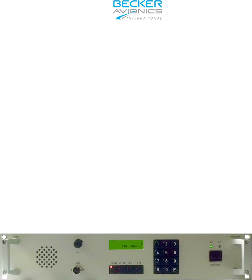
The station has a simple user-friendly HMI; the main components on its front panel are the 2-line 16
character liquid-crystal display (LCD) and several control elements (rotating knob and buttons). The selected
frequency and operating status of the equipment, displayed on the LCD, inform about the current operating
mode. Control elements (knob, buttons) enable the user to change operating modes or operating frequency.
Standby switch selected to “Standby” partially shuts down the TG660 internal power supply. Some circuitry
of the power supply continue listening to the “Standby Switch” to repower the unit at any time. The “ON/OFF”
switch, located on the rear panel, disconnects from AC supply completely.
Fig. 1 - 1 Front side
The VHF transceiver TG660 is available in a 6W, 10W, 25W or 50W transmit power version.
An antenna mismatch of ≥ 4:1, detected on the transmitter output terminal, cause automatic output power
reduction to 40 % of the declared nominal TX power.
The VHF transceiver is protected against jammed transmit button or short circuit on the PTT line. Factory
setting of the time limit to release a “stuck PTT” is 2 minutes.

TG660-(XX)
_____________________________________________________________________________________________
DV 17900.03-BAI Issue 2 03/2016 Page 3
1.3.1 Microphone Inputs
Several microphone inputs are available for the following types:
Standard microphone unbalanced, DC coupled and providing power supply for the mike,
Dynamic mike input balanced and
Symmetrical line input.
These microphone inputs connect to a dynamic volume compressor inside of the remote controlled
transceiver, which keeps the modulation voltage constant ≥ 80% over a wide mike-signal input voltage
range.
1.3.2 Audio outputs
The TG660 has four different outputs:
Headphone output
Speaker output (speaker is switched off in transmit mode)
Line out
Voice recorder
The headphone output level provide 100mW @ 600Ω. The rated loudspeaker output power is ≥ 4W sin @
4Ω. The LINE_OUT – AF output nominal output level is zero (0) dBm @ 600Ω. The levels on headphone
and speaker output are adjustable by means of the volume potentiometer within the range -20...+10 dBm.
The voice recorder output level is – 6 dBm @ 600Ω balanced.
1.3.3 Side tone output
In transmit mode, the side tone signal is routed to the line and phone output.
1.3.4 TG660 internal Sub Modules
The “Control Board”, located behind the front panel of the TG660, consists of the LC Display and all the
Human Machine Interface (HMI) (e.g. Keypad, Function Switches and the Volume Control). All changes
made from the “Control Board“ are transferred to the “Interface Board” on which a microcontroller exchanges
control information with the remote control transceiver like change of frequency, volume adjustment, “SQL”
on/off and other parameters of the equipment. The microcontroller on the “Interface Board” handles the serial
communication interfaces and by means of a Remote Control Unit which provide all settings of operating
parameters on the VHF transceiver TG660. (Web Browser via IP)
The loudspeaker, located behind the front panel, switch off automatically during TX. This avoids acoustic
coupling between loudspeaker and the microphone, which can cause acoustical feedback.
The RF power amplifier is located in the center of the chassis behind the front panel. The PA3-2AB-AIR-1
model is a mobile Air Band AM VHF RF power amplifier which can deliver 25 watts or 50 watt (depending on
the TG660-(XX) version) of RF power when driven with 8/10 watts and it will cover the frequency range from
118 - 138 MHz. The amplifier’s dimensions are: 7.5”L x 2.2”H x 3.7”W.

TG660-(XX)
_________________________________________________________________________________________________
Page 4 DV 17900.03-BAI Issue 2 03/2016
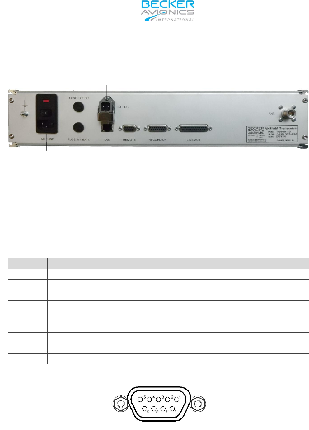
1.3.5 Rear panel
Following items are on the rear panel of the transceiver TG660 mounted.
Equipment connectors for:
AC/DC power supply,
Voice Recorder,
IP Interface,
Record/DF,
Line Aux.
Antenna socket.
1.3.6 Self-test
After the TG660 turned “ON” a system self-test is performing. Detected errors show up on the display
otherwise the unit changes into the last used operation mode.
1.4 TG660 Variants and Options
Part-No.:
Description
Article-No.:
TG660-(05)
VHF-AM Transceiver, 118-137 MHz,
25/8.33 kHz, 6 W
0635.367.926
TG660-(10)
VHF-AM Transceiver, 118-137 MHz,
25/8.33 kHz, 10 W
0635.375.926
Option 1 Internal battery 0640.131-958
Option 2 Radio over IP “ROIP” 0640.141-958
Notes:
1) All TG660 models are combinable with Option 2.
2) The Option 1 only applies to the TG660-(05) and TG660-(10) models.
TG660-(25) VHF-AM Transceiver, 118-137 MHz,
25/8.33 kHz, 25 W 0940.449.926
TG660-(50) VHF-AM Transceiver, 118-137 MHz,
25/8.33 kHz, 50 W0940.447.926

TG660-(XX)
_____________________________________________________________________________________________
DV 17900.03-BAI Issue 2 03/2016 Page 5
1.5 Technical Data
General data:
• Frequency range:
118.00-136.990 MHz
• Channel spacing:
25 kHz / 8.33 kHz,
automatically selected
• Modulation type:
AM, 6K80A3EJN (25 kHz) & 5K00A3EJN (8,33 kHz)
•AC-Power:
90 VAC....250 VAC,
45 Hz...65 Hz
• DC-Power external:
Nominal: 24 VDC
Range: 21 VDC ...29.8 VDC
• RF Antenna connection:
N-Connector, female
•Warm up time:
5 sec.
• Duty cycle:
RX/TX: 4 : 1
• Voice recorder output:
-6 dBm, +3 / -12 dB @ 600 Ω, balanced
Environmental data:
•Temperature range: Operating -20°C....+55°C
Storage -55°C....+85°C
•Humidity:
48h, 50°C, 95% RH,
without condensation
Dimensions (W x D x H):
•Case:
428 x 280 x 86.5 mm
•19 inch Unit:
482.6 x 280 x 88.1 mm
Weight:
4.5 kg without internal battery
6.5 kg with internal battery
5.6 kg with internal PA (25W & 50W versions)
Transmitter data:
•Carrier power:
• Frequency stability:
• Protection of the transmitter:
6W, 10W, 25W or 50W, depending on transceiver model no.
±1 ppm
VSWR = 6 without any damage
• Modulation depth: 85% m 95%
• Modulation distortion: 10%
•AF-Response. 350 Hz….2500 Hz (8.33 kHz)
2 dB ≥ ripple ≥ -4 dB
• Adjacent channel power: 50 dB (8.33 kHz),
60 dB (25 kHz)
•AF-Line input level: -20 dBm to 10 dBm adjustable
•AF-Line input impedance:
• Local Mike sensitivity (dyn.)
600 Ω +/- 10%, balanced
2 mV to 10 mV @ 200 Ω, balanced

TG660-(XX)
_________________________________________________________________________________________________
Page 6 DV 17900.03-BAI Issue 2 03/2016
Receiver data:
• Sensitivity (Mod. Depth 30%):
-101 dBm for 12 dB SINAD
• Effective bandwidth:
≥ 2.8 kHz, 8.33 kHz Channel
≥ 8.5 kHz for 25 kHz Channel
•AF-Response: 8.33kHz
350 Hz....2500 Hz
2 dB ≥ ripple ≥ -4 dB,
reference 0 dB @ 1kHz
25 kHz
350 Hz....3400 Hz
2 dB ≥ ripple ≥ - 4 dB,
reference 0 dB @ 1kHz
• Adjacent channel rejection:
≥ 60 dB
• Spurious response rejection:
≥ 70 dB
• Inter-Modulation
response rejection:
≥ 70 dB
• Blocking or desensitisation:
≥ 80 dB
• Cross modulation rejection:
≥ 80 dB
• Squelch operation:
• Audio noise:
• RF-Input level range:
• RF-Dynamic range:
• AF-AGC for 30% m 90%:
• AF-Line output level:
• AF-Line output impedance:
• Local headphone output power:
• Ext./Int. speaker power:
6 dB S+N/N 12 dB,
adjustable on front panel by software setting,
override level -85 dBm
≥ 40 dB S+N/N @ -13 dBm
-101 dBm RF level 10 dBm
6 dB AF variation for 100 dB
RF variation
AF-Level variation 1.5 dB
-20 dBm to 10 dBm,
adjustable with internal potentiometer
600 Ω +/- 10%, balanced
≥ 1.5 V @ 600 Ohm,
unbalanced, volume control
located on front panel
≥ 4 W sinus @ 4 Ω, Volume
control at the front panel

TG660-(XX)
_____________________________________________________________________________________________
DV 17900.03-BAI Issue 2 03/2016 Page 7
1.6 Accessories
Antenna connector for RG 213 / 214 coax-cable Article no.: 0716.502-277
Cable connector (soldering)
15 pin D-SUB (male) Article no.: 0726.303-277
9 pin D-SUB (male) Article no.: 0344.699-277
25 pin D-SUB (male) Article no.: 0584.940-954
Cable connector (crimp)
15 pin D-SUB (male) Article no.: 0812.803-227
9 pin D-SUB (male) Article no.: 0820.970-277
25 pin D-SUB (male) Article no.: 0584.983-954
Hand mike dynamic with cable Article no.: 0344.214-951
cable and 5-pole DIN connector 1PM012
1PH028 Headset, dynamic Mike, 200 Ω, Article no.: 0860.557-951
Headphone 300 Ω, 5-pin DIN connector
1PH030 Headset, dynamic Mike 200 Ω, Article no.: 0574.775-951
Headphone 600 Ω, 5-pin DIN connector
Lightning protection, overvoltage protection Article no.: 0600.891-277
Antenna 1A049 Article no.: 0812.064-952
Manuals
Installation and Operation DV17900.03 Article no.: 0639.583-071
Maintenance and Repair DV17900.04 Article no.: 0639.591-071
Operating Instructions Article no.: 0640.549-071

TG660-(XX)
_________________________________________________________________________________________________
Page 8 DV 17900.03-BAI Issue 2 03/2016
Blank

_____________________________________________________________________________________________
DV 17900.03-BAI Issue 2 03/2016 Page 9
2 Section 2 INSTALLATION
2.1 Installation in an ATC desk
2.1.1 General
Two version of TG660 are available, one without 19 inch housing for installation in an Air Traffic Control
(ATC) desk and the other as stand-alone 19 inch VHF transceiver with an own desk cabinet. The following
instructions thus apply only in a general way.
Only qualified and authorized personnel shall perform the installation the TG660.
2.1.2 Pre-installation check
When unpacking the goods inspect all deliveries in respect to be free from any damage that might occur
during transport and check in accordance with the delivery note completeness of the whole ship-set.
2.2 Mechanical installation in a 19-inch equipment rack
The design of the TG660 is compliant to install requirements in standard 19-inch rack or in ATC desk.
2.3 Thermal considerations
When powered, the TG660 generates only limited heating, thus requiring no specific cooling system (e.g.
forced cooling). However, consider sufficient space for convection at installations in a rack or a controller
desk.
2.4 Electrical installation of the TG660
115 or 230 VAC is main supply voltage for the TG 660.
WARNING
CAUTION
TG660-(XX)
_________________________________________________________________________________________________
Page 10 DV 17900.03-BAI Issue 2 03/2016
2.4.1 Grounding TG660 housing
The grounding terminal (M 4 screw with nut), which is clearly marked with the grounding symbol, is located
on the rear side of the 19 inch rack. Connect this terminal directly to the next potential equalisation rail or
grounding point of the building. Use an adequately dimensioned cable of 10 mm2, coloured green/yellow.
NOTE
Observe the relevant national safety precautions.
2.4.2 Radio frequency radiation
The station shall be used only with antenna systems which are qualified for operation in ATC mobile
communications service and for which the radio frequency radiation hazard awareness operations and
maintenance personal is provided.
The station may become a cause of radio frequency radiation hazard if installation incorrectly, not grounded,
or if used with unapproved antenna systems.
2.4.3 Lightning protection
Install a lightning protection element in the antenna coaxial cabling to protect the station from lightning strike
or static discharge at the antenna. Connect the grounding terminal of the lightning protection element to the
potential equalisation rail of the building or any other low impedance ground via an adequately sized cable.
2.4.4 Installation of antenna system
For safety reasons the antenna system should be installed only by qualified personnel. The correct
installation and grounding of the antenna system is an essential precondition for trouble free operation of the
VHF ground station.
2.5 Pin connection front panel
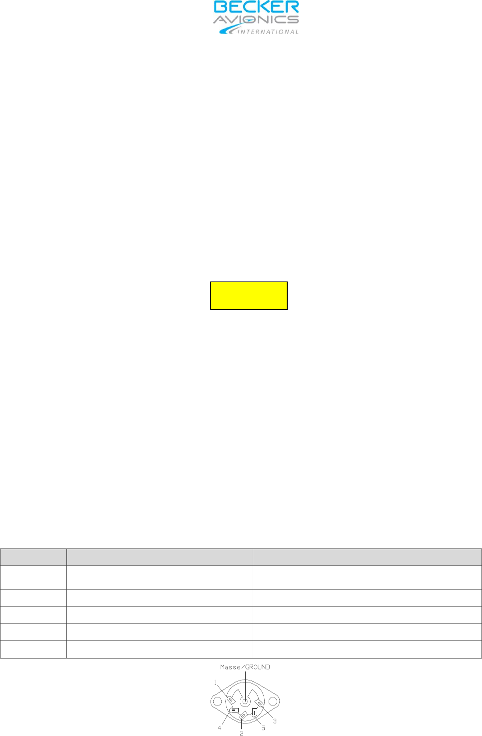
2.5.1 Pin connection mike connector (MIC)
Pin
Signal
Description
1
GND
AF Signal Ground, Mike Shield and Return for
PTT
2
MIKE HI
Microphone AF Signal HI
3
HEADPHONE
Headphones AF Signal HI
4
MIKE LO
Microphone AF Signal LO
5
PTT
PTT Switch Input
rear view
WARNING
TG660-(XX)
_____________________________________________________________________________________________
DV 17900.03-BAI Issue 2 03/2016 Page 11
2.6 Pin connection rear panel
Fig. 2 - 1 Rear side
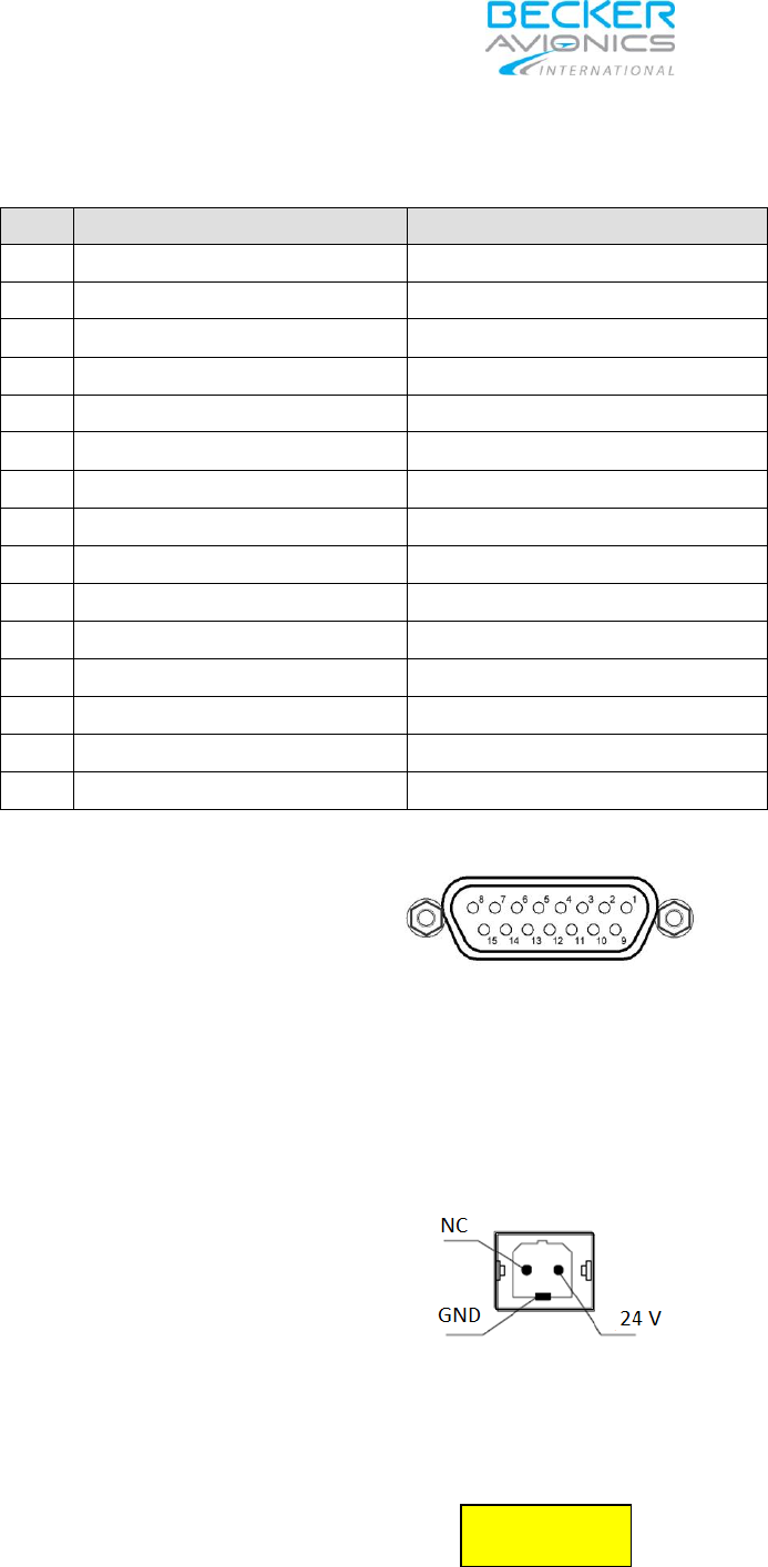
2.6.1 Remote control 9 PIN D-SUB connector (female)
Pin
Signal
Description
1
RX-
RS422 Data line
2
TX-
RS422 Data line
3
RX+
RS422 Data line
4
TX+
RS422 Data line
5
Shield
GND
6
NC
No Connection
7
NC
No Connection
8
NC
No Connection
9
NC
No Connection
rear view
EARTH
connection
FUSE1 DC
DC extern
Antenna Connection
AC connector
IP
connector
FUSE2
internal
battery
LINE/AUX
connector
Record /
DF
connector
Remote
connector
r

TG660-(XX)
_________________________________________________________________________________________________
Page 12 DV 17900.03-BAI Issue 2 03/2016
2.6.2 Line/AUX 25 PIN D-SUB connector (female)
Pin
Signal
Description
1
DC Out
Auxiliary voltage output 12 V, max 1A
2
DC GND
Auxiliary voltage ground
3
Line Out (HI)
AF output 0 dBm 600 Ohm
4
Line Out (LO)
AF output 0 dBm 600 Ohm
5
PTT Line (HI)
PTT activation
6
SQL Line (HI)
Squelch output HI
7
Line IN (HI)
AF input 0 dBm 600 Ohm
8
Line IN (LO)
AF input 0 dBm 600 Ohm
9
Line IN (M)
AF input transformers centre connection
10
RX_AGC
Receiver audio gain control output
11
Mike EXT (HI)
External microphone input Dyn/Electret
12
Mike EXT (LO)
External microphone input Dyn/Electret
13
Chassis
Chassis ground
14
PTT Line (LO)
PTT activation LO
15
SQL Line (LO)
Squelch output LO
16
Line Out (M)
Line Out transformer centre connection
17
PTT ext. (HI)
External PTT HI
18
PTT ext. (LO)
External PTT LO
19
NC
No connection
20
AF GND
AF ground
21
SPK (HI)
Loudspeaker signal
22
SPK GND
Loudspeaker ground
23
Error (HI)
Error detection, potential-free
24
Error (LO)
Error detection, potential-free
25
Chassis
Chassis ground
rear view
TG660-(XX)
_____________________________________________________________________________________________
DV 17900.03-BAI Issue 2 03/2016 Page 13
2.6.3 Record / DF 15 PIN D-SUB connector (female)
PIN
SIGNAL
DESCRIPTION
1
DF_BL (HI)
DF Blank (HI)
2
DF_BL (LO)
DF Blank (LO)
3
GND
Ground
4
VR_Out (HI)
Voice Recorder out (HI)
5
VR_Out (LO)
Voice Recorder out (LO)
6
GND
Ground
7
NC
Not connected
8
VR_Act (HI)
Voice recorder control active (HI)
9
VR_Act (LO)
Voice recorder control active (LO)
10
NC
Not connected
11
NC
Not connected
12
NC
Not connected
13
NC
Not connected
14
NC
Not connected
15
NC
Not connected
rear view
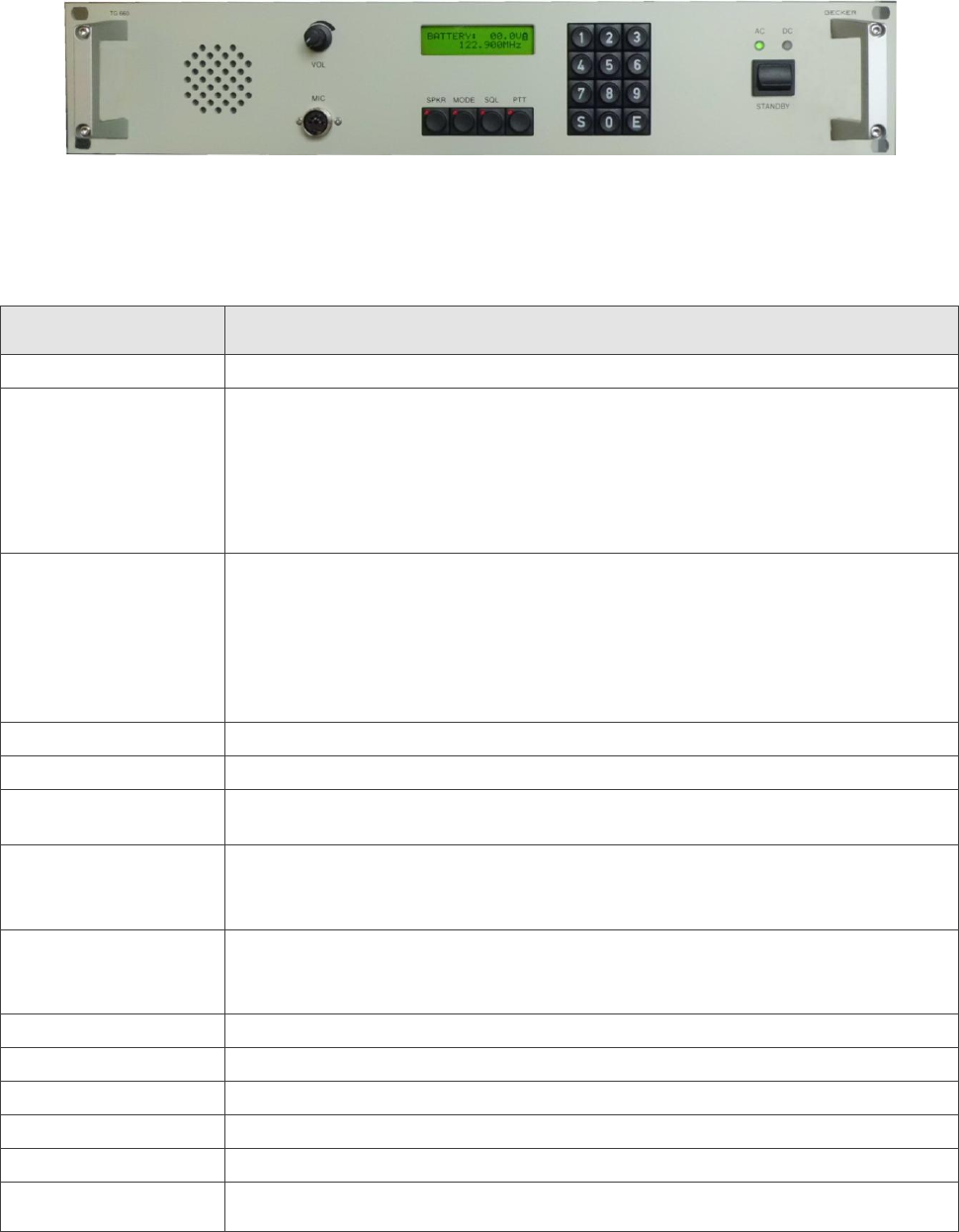
2.6.4 EXT. DC INPUT 2 PIN connector
front view
A 24 VDC supply cable is connectable to the jack “DC extern” located on the rear panel of
the TG660.
Ensure correct polarity of the DC leads!
An adequately dimensioned cable of 1.5 mm2 or thicker shall be used for this purpose.
CAUTION

TG660-(XX)
_________________________________________________________________________________________________
Page 14 DV 17900.03-BAI Issue 2 03/2016
N O T E
24 VDC input cannot be separated from external DC power supply by means of a dedicated switch.
Disconnect the DC supply cable at “EXT.DC” input connector for this purpose.
2.6.5 AC / LINE power supply connector
The “AC / Line” power adapter on the rear side of the TG660 provides a socket to connect 220V/115V from
the AC source via the cable IEC 60-320-1 and additionally an ON/OFF switch to disconnect AC power from
all TG660 circuits.
NOTE
The TG660 power supply logic operates with AC-power by default. After AC-power failed, the logic
automatically switches over to DC-power. The moment AC-power becomes available the logic returns back
to AC-power source.
An optional internal 12 VDC battery, installed inside the TG660, provide enough power to continue operation
of the TG660 in case AC and DC supply voltage would fail the same time. During battery operation the TX
power of a 10 W receiver will be reduced to 6 W (emergency operation).
2.7 LINE / AUX connection
PTT-LINE (HI)
Pin 5
PTT connection, HI
PTT-LINE (LO)
Pin 14
PTT connection, LO
NOTE
“PTT-LINE” (HI/LO) - (optically decoupled PTT input, active at 12 V ± 1 V). If 12 VDC applied to this input, TX
activates and TX modulation input of the transceiver switches internally to
“LINE-IN” input.
2.7.1 Connection of an external speaker
The TG660 allow connection of an external loudspeaker. The external loudspeaker must be connected to pin
21 “SPK HI” (+) and pin 22 “SPK LO” (-) of the “LINE AUX” connector. The cable length between speaker
and connector shall be ≤ 3 m.
The output is not galvanically decoupled. The “SPKR” (LO) lead connects internally to signal ground. The
output “SPKR” (HI) has coupling capacitor, connected internally, in series. The max output power is 3 Watts
at 4 Ω.
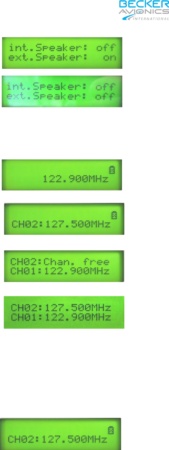
2.7.2 External speaker
Pressing “SPKR” key for approx. 2 sec enables / disables external loudspeaker, the display shows the status
of the external and internal speaker for approx. 1 second.
2.7.3 Internal speaker
Pressing “SPKR” key shortly enables / disables the internal loudspeaker, the display shows status of the
internal and external speaker for approx. 1 second.

TG660-(XX)
_____________________________________________________________________________________________
DV 17900.03-BAI Issue 2 03/2016 Page 15
2.7.4 Headphone connection
Connect only headphones with an impedance of 600 Ohm and a nominal output power of 100 mW to the
headphone output on the front plate. This output is not galvanically decoupled.
A ”VOLUME” knob on the front panel allow control of audio loudness.
Phone
Pin 3
Headphones AF signal
GND
Pin 1
Signal ground
2.7.5 Connection LINE IN / LINE OUT
The “LINE IN” input is a balanced AF input.
An AF transformer decouples galvanically from housing and internal signal ground. The AF transformer has
centre tap connected to pin 9 “LINE_IN” (C). Nominal load resistance is 600Ω and nominal output level is 0
(zero) dBm @ 600Ω. PTT control and CALL indication provided by using the centre tap without additional
control lines.
LINE_IN (HI)
Pin 7
AF Signal from Communication Equipment
LINE_IN (LO)
Pin 8
AF Signal from Communication Equipment
LINE_IN (C)
Pin 9
Centre Tap of “LINE_IN” input
The LINE OUT output is a balanced AF output
The “RX AF” signal from the station is present at this output. By an AF transformer “LINE OUT” signal
galvanically decouples from housing and internal signal ground. Center tap of the AF transformer connects
to pin 16 – “LINE_OUT” (C). Nominal load resistance 600Ω, nominal output level 0 (zero) dBm @ 600Ω.
LINE_OUT (HI)
Pin 3
AF Signal from Communication Equipment
LINE_OUT (LO)
Pin 4
AF Signal Communication Equipment
LINE_IN (C)
Pin 16
Centre Tap of “LINE OUT” output
2.7.6 Connection SQL - LINE
The “SQL-LINE” (HI/LO) is an optical-isolated switching control line. The signal HI/LO indicates the presence
of received RF signal.
RX squelch is open if the switch is closed. This signal provides indication of a call on remote communication
equipment. Maximum switching current is 20mA. Voltage drops at 20mA not more than 1V. Maximum
switching voltage is 65V.
SQL_LINE (HI)
Pin 6
CALL Indicator
SQL_LINE (LO)
Pin 18
CALL Indicator

TG660-(XX)
_________________________________________________________________________________________________
Page 16 DV 17900.03-BAI Issue 2 03/2016
2.7.7 Output PTT LINE (HI/LO)
“TX_ACT LINE” (HI/LO) is an optical-isolated switching control line. The switch closes as long as TX is
active. Maximum switching current is 20 mA. Voltage drop at 20 mA not more than 1V. Maximum switching
voltage is 65V.
PTT LINE (HI)
Pin 5
TX ACTIVE Indicator
PTT LINE (LO)
Pin 15
TX ACTIVE Indicator
2.7.8 Input PTT_AUX LINE (HI/LO)
“PTT_AUX LINE” (HI/LO) is an optical-isolated switching control line. Maximum switching current is 20mA.
Voltage drop at 20mA not more than 1V. Maximum switching voltage is 65V.
PTT ext. (HI)
Pin 17
PTT for Auxiliary TX
PTT ext. (LO)
Pin 18
PTT for Auxiliary TX
2.8 Microphone connection
2.8.1 Mike connector (MIC) front plate
The signals “MIKE (HI)” and “MIKE (LO)” are the balanced AF inputs of the TG660 (input impedance 200 Ω,
nominal input voltage 10mV. The microphone connection on the front plate is foreseen connecting dynamic
microphones by default, carbon microphone operation available from configuration only.
MIKE (HI)
Pin 2
Microphone AF signal
MIKE (LO)
Pin 4
Microphone AF signal
2.8.2 LINE/AUX connector (rear side of TG660)
The TG660 allows the connection of an external microphone. If respectively configured the microphone
amplifier can operate with both, standard carbon- or dynamic mike.
Microphone selection
The microphone type can selected via the web browser connection. Adjustment of input levels and priority
for connected microphones also provided.
Standard (carbon) microphone
For operation with standard microphone (carbon) the station has a balanced input with input resistance 150Ω
and nominal sensitivity 250 mV. 12 volts DC power for standard microphones provided via a feed resistor
470 Ω.
Dynamic microphone
For operation with dynamic microphone, the station has a balanced input with an impedance of 200 Ohm
input resistance and a nominal sensitivity of 2 mV.

TG660-(XX)
_____________________________________________________________________________________________
DV 17900.03-BAI Issue 2 03/2016 Page 17
2.9 Auxiliary Voltage output
The auxiliary voltage output is suitable for supply the optical isolated applications. The output voltage is 12
Volts @ 1A maximum.
DC out 12V/1A
Pin 1
DC GND
Pin 2
2.10 Record/DF connector
2.10.1 AF output to Voice Recorder
TX side tone and RX AF signals from the ground station are present at this output for recording the
information. The output galvanically decoupled from housing and internal signal ground. Nominal load
resistance is 600 Ω, nominal output level 547 mV @ 600 Ω.
VR_OUT (HI)
Pin 4
Audio to Voice Recorder
VR_OUT (LO)
Pin 5
Audio to Voice Recorder
2.10.2 Voice Recorder control
This signal provides control of the voice recorder. Maximum switching current is 20 mA. Voltage drops at 20
mA not more than 1V. Maximum switching voltage is 65V (optically-isolated contact).
The switch closes, either if TX is active or if RX squelch is open. This means, both transmit and receive
signals are recorded if a voice recorder is connected.
VR_ACT (HI)
Pin 8
Voice Recorder Activation Control
VR_OUT (LO)
Pin 5
Voice Recorder Activation Control
2.10.3 Direction Finder blank-out
The switching output provides automatic control to blank-out during transmit the Direction Finder (blanks out
Direction Finder during transmission).
The switch (Optically-isolated contact) is closed if TX is active. Maximum switching current is 20 mA. Voltage
drop at 20 mA not more than 1V. Maximum switching voltage is 65V.
DF_BL (HI)
Pin 1
DF Blanking Signal
DF_BL (LO)
Pin 2
DF Blanking Signal

TG660-(XX)
_________________________________________________________________________________________________
Page 18 DV 17900.03-BAI Issue 2 03/2016
Blank
_____________________________________________________________________________________________
DV 17900.03-BAI Issue 2 03/2016 Page 19
3 Section 3 OPERATION
3.1 Controls and Indicators of TG660
Fig. 3 - 1 Controls and indicators
3.2 Symbol Meaning on Controls and Indicators
Description
Function
STANDBY switch
Switches the station ON/OFF
SPKR key
The “SPKR” key provides switching “ON / OFF” of the internal and external
loudspeaker.
A short press on SPKR” key enables/disables the internal loudspeaker and a
longer press (approx. 2 sec.) enables/disables the external loudspeaker.
Approximately 1 sec after each change process the display shows the actual
status of both loudspeakers.
MODE key
Selection of modes:
Normal Operating mode (frequency selection via Key-pad)
Channel mode (selection of predefined channels)
Several long presses on the “MODE” key show the status of different
supply voltages (e.g. Radio, DC-In and Optional Battery)
SPKR key LED
The LED lights up as long as the internal speaker enabled.
MODE key LED
The LED lights up as soon as the system self test detected an error.
SQL key LED
The LED lights up during receive of a signal. If the SQL is disabled the LED is
continuously blinking.
PTT key LED
The LED lights up during the TG660 is in transmit mode. If the transmitter is
continuously “ON” for more than 2 minutes, the transmitter shuts down
automatically. The PTT LED is blinking until keying interrupts.
SQL key
Each short press on “SQL” key switches the squelch ON/OFF. A long press on
squelch key activates the SQL threshold setting function. Another short press
returns the TG660 into the previous mode.
Key (E)
Use Key (E) to acknowledge keypad re-entries.
Key (S)
Storage key
Keys 0 – 9
Numerical keypad
VOL knob
The “VOL” knob allows adjustment of loudspeaker volume.
AC/DC LED
The AC/DC LED´s indicate which supply voltage is available.
MIC
The “MIC”-socket provide connection of a dynamic hand mike or a head set.

TG660-(XX)
_________________________________________________________________________________________________
Page 20 DV 17900.03-BAI Issue 2 03/2016
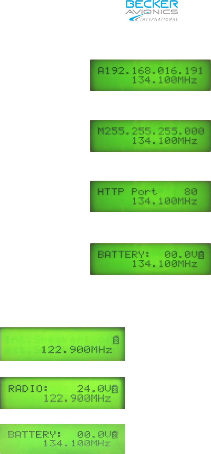
3.2.1 Power “ON”
Turn on the TG660 by means of the STANDBY switch on the front plate. The Logo ” Becker Avionics”
appear for 2 seconds on the LC display.
Depending on which power source is available, the associated indication at the front panel light up,
(LED “AC” and/or “DC”).
The TG660 power supply logic is operating with AC-power by default. After AC-power failed, the logic
automatically switches over to DC-power. The moment AC-power becomes available the logic returns back
to AC-power source.
An optional internal 24 VDC battery inside the TG660, if installed, could provide power for continued operation
over a certain time if AC and DC supply voltage would fail the same time.
If the station switches from AC to DC-power or vice-versa, the station is operable with the same functions
and settings as before.
3.2.2 Power on Built In Test (PBIT)
Right after power is applied, the system performs a Display dimming test from minimum to maximum
brightness and thereafter the LCD shows “Becker Avionics and TG 660” for approximately two (2) seconds.
PBIT thereafter starts in a 2 seconds interval to change from the 1st test-step to the next up to the last one.
1. Step The top line can show different information i, bottom line shows the last used frequency refer
to 3.2.3.
2. Step The 2nd picture shows the sample of an top line with the last used mode after a power cycle.
Depending on customers last used mode different information can appear.
The following sample it shows the status of the optional internal battery, if installed.
If not installed, the battery symbol on the right end of top line is crossed out and any actually stored
voltage in a capacitor within the battery control circuit counts slowly downwards until 0 (zero) volts
are reached.
TG660-(XX)
_____________________________________________________________________________________________
DV 17900.03-BAI Issue 2 03/2016 Page 21
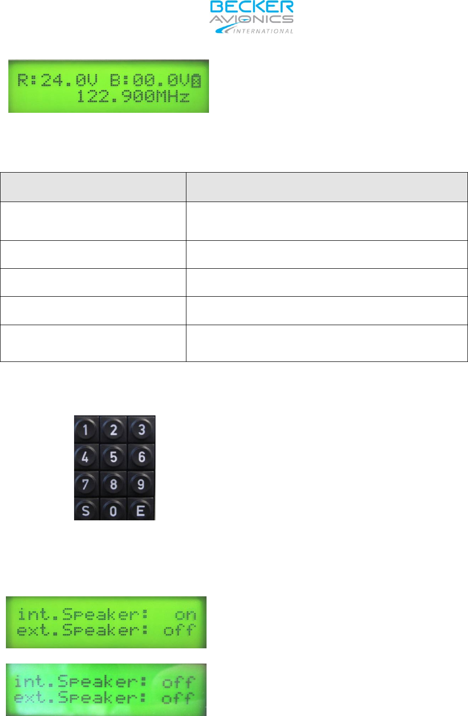
3. Step The 3rd picture shows figures of the IP address in the top line.
4. Step The 4th picture shows figures of the subnet mask in the top line.
5. Step The 5th picture shows the port number in the top line.
6. Step The 6th picture shows the display in last used mode which become active after the PBIT is
completed successful.
Note: The display settings, selected before switch off, restore automatically after PBIT completion.
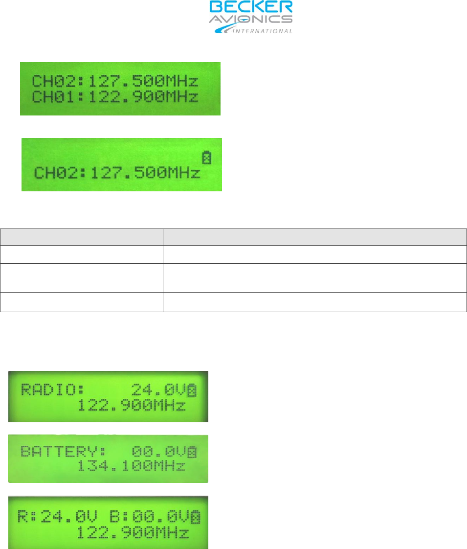
3.2.3 Possible Display Modes
The display shows the frequency and the
status of the battery. The ‘X’ in the battery
symbol indicates no battery option installed.
Press MODE key 1st time for approx. 2
seconds and the upper line of the display
changes, the Radio Voltage become
displayed.
Press MODE key 2nd time for approx. 2
seconds and the upper line of the display
changes, the voltage of the internal battery
become displayed. (optional battery)
TG660-(XX)
_________________________________________________________________________________________________
Page 22 DV 17900.03-BAI Issue 2 03/2016
Press MODE key 3rd time for approx. 2
seconds and the upper line of the display
changes, the Radio power supply voltage
and the voltage of the internal battery
become displayed.
The display shows the frequency and the status of the battery. The ‘X’ in the battery symbol indicates no
battery option installed.
Description
Function
lower line
Indication of active transmit/receive frequency
upper line R: 24,0 V B: 00.0V
Indication of internal DC supply and opt. battery voltage
(if a battery is installed, otherwise shows 00.0V)
upper line shows an arrow
Indicating transmit mode (PTT active)
upper line shows an arrow
Indicating receive signal detected
upper line battery symbol
Shows actual battery voltage status in most of the selectable
operation modes, configuration pages excluded.
3.2.4 Keypad
Use keypad for changing the actual
frequency. Only 25/8.33 kHz frequencies are
accepted. If the new frequency is not
included in the 25/8.33 kHz channel spacing
the upper line blinks.
Type in all 6 digits of the desired frequency
and use key “E” for activation.
3.2.5 SPKR Key
Press SPKR once - internal speaker is
switched on. A red signal light at SPKR knob
lights up.
Press SPKR again - internal speaker is
switched off again. Red signal light will
disappear.
TG660-(XX)
_____________________________________________________________________________________________
DV 17900.03-BAI Issue 2 03/2016 Page 23
Press SPKR approx. 2 seconds; the external
speaker will switched on.
Press SPKR again - external speaker is
switched off again.
3.3 Storage procedure
Adjust the storage frequency in “Standard
Mode”, thereafter press the “S” button.
Select the desired channel number with the
keyboard, key in “02” e.g.
! Engaged channels will be overwritten.
Press “E” button to store this frequency in
CH02.
Vacant channels are displayed with “Chan.
free”
Press the “E” button to save the frequency.
N O T E
The interdependence of the operating channel number and the real operating frequency of the transceiver is
shown under section 3.4.
3.3.1 Channel mode
Make a short press on the MODE button
The display shows a channel input field
TG660-(XX)
_________________________________________________________________________________________________
Page 24 DV 17900.03-BAI Issue 2 03/2016
Dial the desired channel number e.g. “02”
and press the “E” button.
After pressing “E” button the display
shows the dialled channel frequency.
Description
Function
top line
Indication the selected storage channel
top line
Indication of active transmission/reception frequency
(active frequency)
line 24,0 V
Indication of DC supply voltage
3.3.2 MODE Key
Press MODE key 1st time for approx. 2
seconds and the upper line of the display
changes, the Radio Voltage become
displayed.
Press MODE key 2nd time for approx. 2
seconds and the upper line of the display
changes, the voltage of the internal battery
become displayed. (optional battery)
Press MODE key 3rd time for approx. 2
seconds and the upper line of the display
changes, the Radio power supply voltage
and the voltage of the internal battery
become displayed.

TG660-(XX)
_____________________________________________________________________________________________
DV 17900.03-BAI Issue 2 03/2016 Page 25
3.4 Sample of Selectable Frequencies
The table below shows the relation between the real operating frequency and the selected frequency
according to international standards. (refer to: ED-23D, chapter 1.3.2, or ICAO).
Channel Name
Channel Frequency
Channel Spacing
118.000
118.0000 MHz
25 kHz
118.005
118.0000 MHz
8.33 kHz
118.010
118.0083 MHz
8.33 kHz
118.015
118.0166 MHz
8.33 kHz
118.025
118.0250 MHz
25 kHz
118.030
118.0250 MHz
8.33 kHz
118.035
118.0333 MHz
8.33 kHz
118.040
118.0416 MHz
8.33 kHz
118.050
118.0500 MHz
25 kHz
118.055
118.0500 MHz
8.33 kHz
118.060
118.0583 MHz
8.33 kHz
118.065
118.0666 MHz
8.33 kHz
118.075
118.0750 MHz
25 kHz
118.080
118.0750 MHz
8.33 kHz
118.085
118.0833 MHz
8.33 kHz
118.090
118.0916 MHz
8.33 kHz
118.100
118.1000 MHz
25 kHz
...
...
...
136.975
136.9750 MHz
25 kHz
136.990
136.9916 MHz
8.33 kHz
***