Becker Avionics TG660 Aircraft radio User Manual PA3 2AB AIR User s Manual
Becker Avionics, Inc. Aircraft radio PA3 2AB AIR User s Manual
Contents
- 1. Manual_Family
- 2. Manual_PA3-2AB-AIR
- 3. Manual_TG660
- 4. User Manual
- 5. Datasheet
Manual_PA3-2AB-AIR

RF Power Amplifier
PA3-2AB-AIR
lnstallation and Operation
Manual
Issue 1
DV PA3-2AB-AIR-1
March 2016
BECKER AVIONICS INC. 10376 USA Today Way Miramar FL 33025 USA
Telephone +1 (954) 450 3137 Fax +1 (954) 450 3206
http://www.beckerusa.com Email: info@beckerusa.com
TABLE OF CONTENTS
I. PRODUCT DESCRIPTION
II. GENERAL SPECIFICATION
III. OPTIONS
IV. CAUTION
V. OPERATING PRECAUTIONS
VI. INSTALLATION
VII. WARRANTY
VIII. SERVICE
I. PRODUCT DESCRIPTION
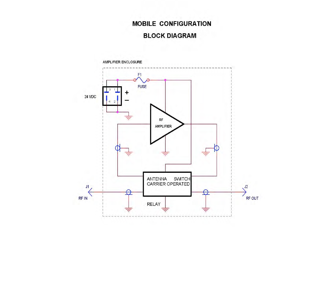
The PA3-2AB-AIR-1 model is a mobile Air Band AM VHF RF power amplifier intended for
use in the mobile applications. This amplifier can deliver 50 watts CW (100 watts PEP) of
RF power when driven with 7 watts CW and it will cover the frequency range from 118-138
MHz.
The mobile amplifier is designed to be installed in the interior of a car or in the trunk.
The PA3-2AB-AIR-1 can be also use as an amplifier module for VHA AM GTA transceivers.
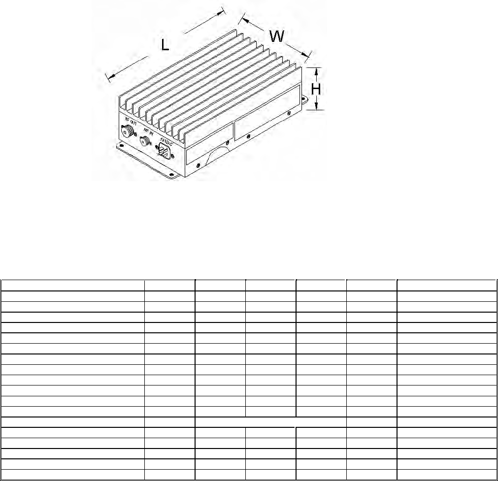
The amplifier’s dimensions are: 7.5”L x 2.2”H x 3.7” W (see figure 1).
Figure 1. Package dimensions.
II. GENERAL SPECIFICATIONS
The general specifications for the VHF amplifier are shown in this section.
Typ
Max
Unit
Condition
Frequency Range
BW
118
138
MHz
Operating bandwidth within range
OBW
20
MHz
Input Power
PIN
6 7.5 10
Watt
CW
Output Power
POUT
50
Watt
CW or 100 W PEP@ M=100%
Gain
G
6
7
8
dB
Output Flatness
ΔPOUT
±1.0
dB
Duty Cycle
D
40
%
per EIA/TIA-603-C
Harmonic Emissions
Har
-67
-62
dBc
POUT = 100 W PEP
Spurious Emissions
Spur
-75
-70
dBc
POUT = 100 W PEP
Operating Voltage
VDD
24 29.8
Volt DC
Supply Current
IDD
2.5
3.0
Amp DC
Avg @ POUT = 100 W PEP
Input VSWR
S11
2.1
VSWR
Operating Mode
Mode
AM / FM / CW
Impedance, Input
ZIN
50
Ω
Impedance, Output
ZOUT
50
Ω
Modulation Linearity
THD
3%
5%
@ M =90%
Receive Path Insertion Loss
IL
0.6
1.0
dB
COR Attack Time
TATK
1.0
2.0
mS

ENVIRONMENTAL CHARACTERISTICS
Parameter
Symbol
Min
Typ
Max
Unit
Condition
Operating Temperature
TO
-20
+60
°C
Storage Temperature
TS
-40
+85
°C
Operating Humidity
HO
0
85
%
relative, non-condensing
Storage Humidity
HS
0
95
%
relative, non-condensing
MECHANICAL PROPERTIES
Parameter
Value
Units
Limits
Condition
Dimensions
7.5” W x 2.2” H x 3.7” D
inch
max
Weight
4
lb
max
RF Connectors In /Out
BNC / TNC”
Cooling
Convection
Vibration
Sinusoidal, 0.35mm -5G, 10 – 150 Hz
max
IEC/EN 60068-2-6
Random Vibration
From 20 to 500Hz - 5G
max
IEC/EN 60068-2-64
Shock
Half-Sine, 11ms(±.5ms) – 15G, in each plane
max
IEC/EN 60068-2-27
III. OPTIONS
The Air Band VHF Mobile Power Amplifiers are available with several options: input, output, fre-
quency ranges and configurations, cases, special logos, etc., when specified at the time of order. We
work closely with you, our customer, to develop products that are in complete compliance with your
needs and specifications.
IV. CAUTION!
EXPENSIVE COMPONENTS MAY BE DESTROYED IF THE AMPLIFIER IS TURNED ON IN A
DAMAGE CONDICTION.
CAUTION:
This amplifier produces RF voltages that can cause painful and dangerous burns. Use
caution! Connect and disconnect all RF connections with the drive power and DC power off.
DRIVE POWER:
RF power transistors, although quite rugged in most respects, are easily damage by
overdrive. Be careful not to overdrive the amplifier even momentarily (before applying any
drive signal please check table I for details). Higher-than-rated drive power may destroy the
transistors and VOID ANY WARRANTY.
SUPPLY VOLTAGE:
The maximum operating voltage is 29.8 VDC. When using the DC power supply make sure
that it is not adjusted above 29.8 volts. If it is possible for the voltage to go above 29.8 Volts
for any reason, including failure of the power supply, install a “crowbar” circuit to prevent
damage to the amplifier in the event of excess voltage.
CASE TEMPERATURE
High power can mean high temperatures. Mount the amplifier where air can freely circulate
over it and where clothing, blankets, etc. will not accidentally be placed over it. Keep duty
cycle below limits.
TERMINATIONS
The efficiency of this amplifier will degrade if it is operates into anything but a 50 Ω load.
Lowered efficiency may mean any or all of the following: lower power output, increased
current drain, higher operating temperature, and reduced life time.
VI. INSTALLATION
The PA3-2AB-AIR amplifier installation is illustrated in figure 2. Mount the amplifier as close to the
antenna as practical. Keep coaxial cable runs short, avoiding sharp bends and pinching. Avoid loose
connectors at the ends of the coaxial cables. The antenna should be matched to an SWR better than
1.5:1 for best results. Higher SWR will degrade the performance of the amplifier.
Mount the amplifier away from the sources of heat, and where air can freely circulate around it. Avoid
mounting the amplifier in the engine compartment or near the exhaust pipe system.
It is also important to securely fasten the unit. An improperly mounted piece of equipment is subjected
to damage as it moves about and can cause serious injuries in an accident. Use bolts through the
holes in the amplifiers flange to fasten the unit to a secure mounting surface (see figure 2).
V. OPERATING PRECAUTIONS
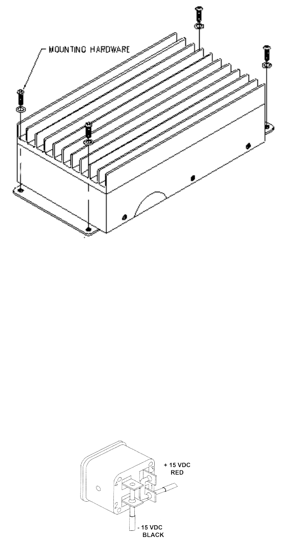
Figure 2. Amplifier installation
(for refenrce only)
Wire the DC power connector (Cinch 4 pin female) directly to the battery if possible. Do not use the
present vehicle wiring. Use #12 AWG if possible and certainly no lighter than #14 AWG. To avoid a
possible fire, or other possible damage, make sure a fuse or circuit breaker is installed at the battery
end of the wire.
Attach DC input wires in accordance to the diagram in figure 3. If wires are too large for the holes,
solder them to the sides of the blades.
Figure 3. DC Connector Internal Wiring
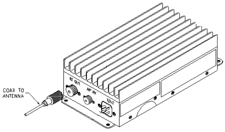
Connect the antenna to the “RF OUT” terminal with a 50Ω coaxial cable and a TNC male
connector according to figure 4.
Turn off your radio transceiver. Connect it to the “RF INPUT” terminal with a 50Ω coaxial cable and
a BNC male connector.
Figure 4. Antenna Connection
(for reference ony)
VII. WARRANTY
BECKER AVIONICS has tested and found this unit to function properly and to operate within the
parameters of its stated specifications.
BECKER AVIONICS warrants that this product is free from defects in material and
workmanship. If found to be defective within two (2) years from the date of purchase, the factory will,
at its discretion, either repair or replace the unit at no cost, provided the unit is delivered by the owner
to the factory intact. The warranty does not apply to any product which as been subjected to misuse,
neglect, accident, improper installation or used in violation of the instructions furnished by BECKER
nor does it extend to units which have been repaired or altered outside our service department, nor
where the serial number has been removed, defaced or changed.
VIII. SERVICE
For service on this amplifier, contact:
BECKER AVIONICS
Customer Service Department
Phone: (954) 450-3137
FAX: (954) 450-3206
EMAIL: info@beckerusa.com
For information on other
BECKER products visit our web site at:
www.beckerusa.com