Controlled Electronic Management Systems S700PXV1-00 S700 multi smart card reader User Manual
Controlled Electronic Management Systems Ltd S700 multi smart card reader
UserManual.wiki
>
Controlled Electronic Management Systems
>
S700PXV1-00 User Manual
>
User Manual
Contents
1.
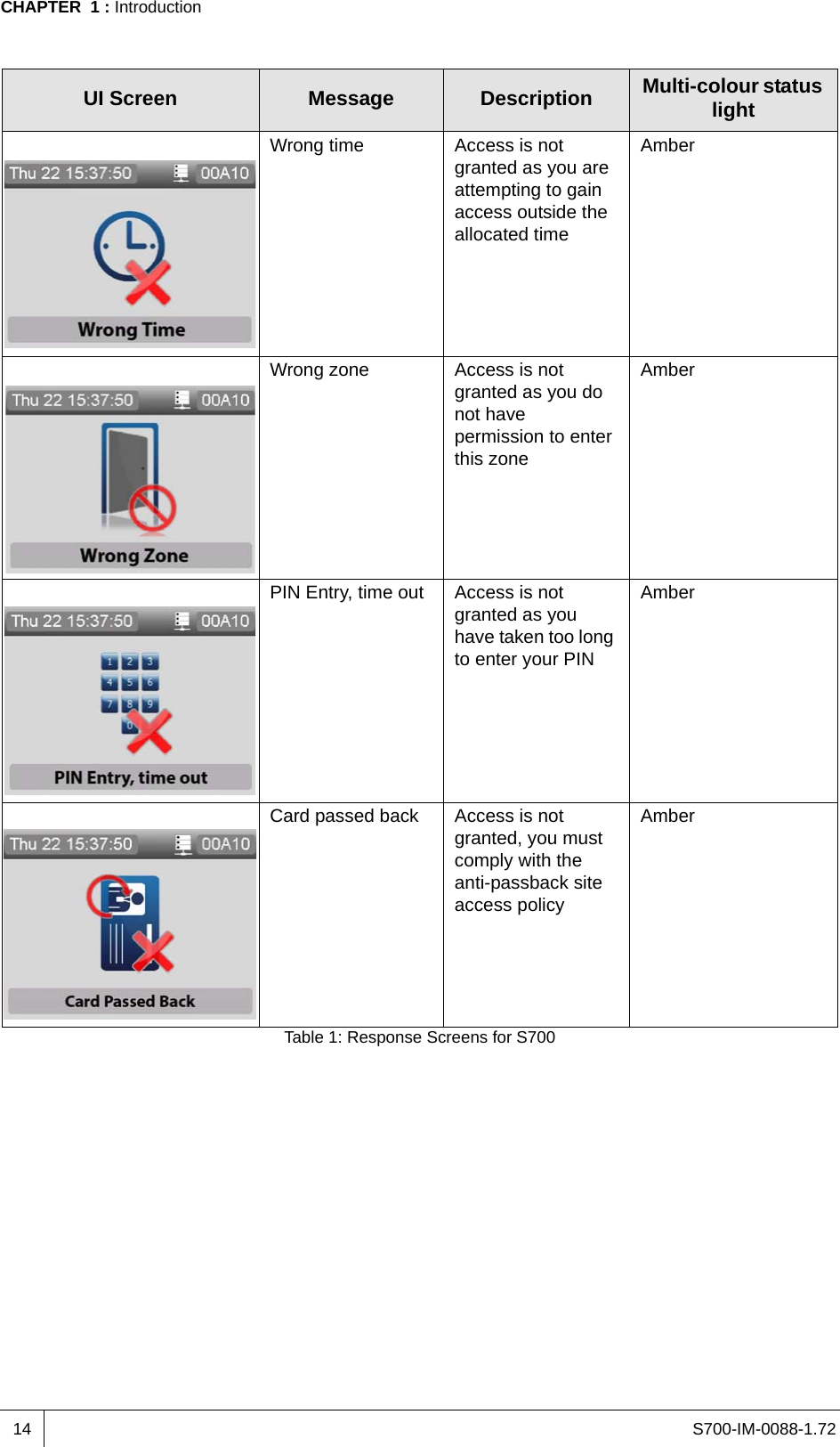
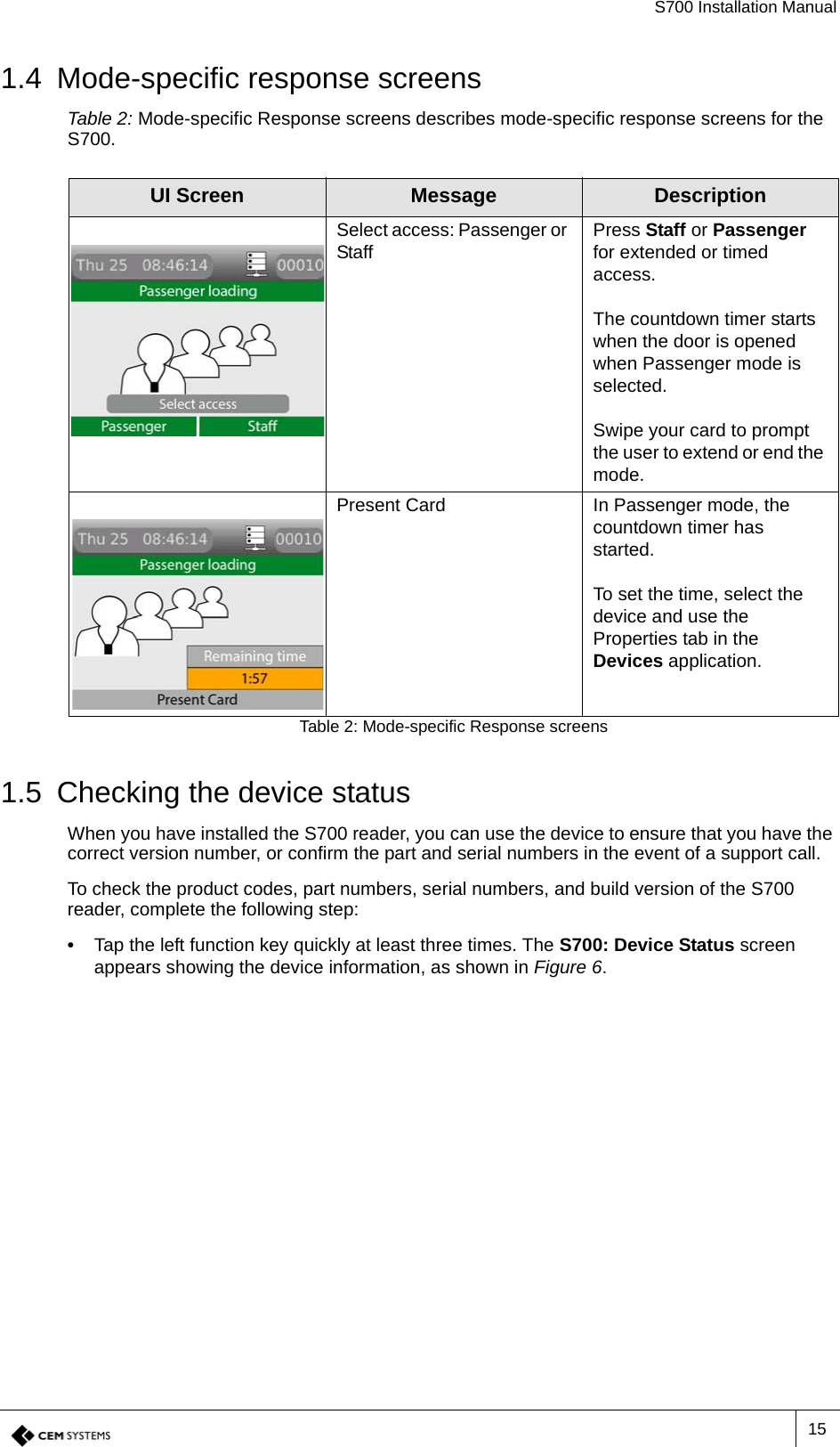
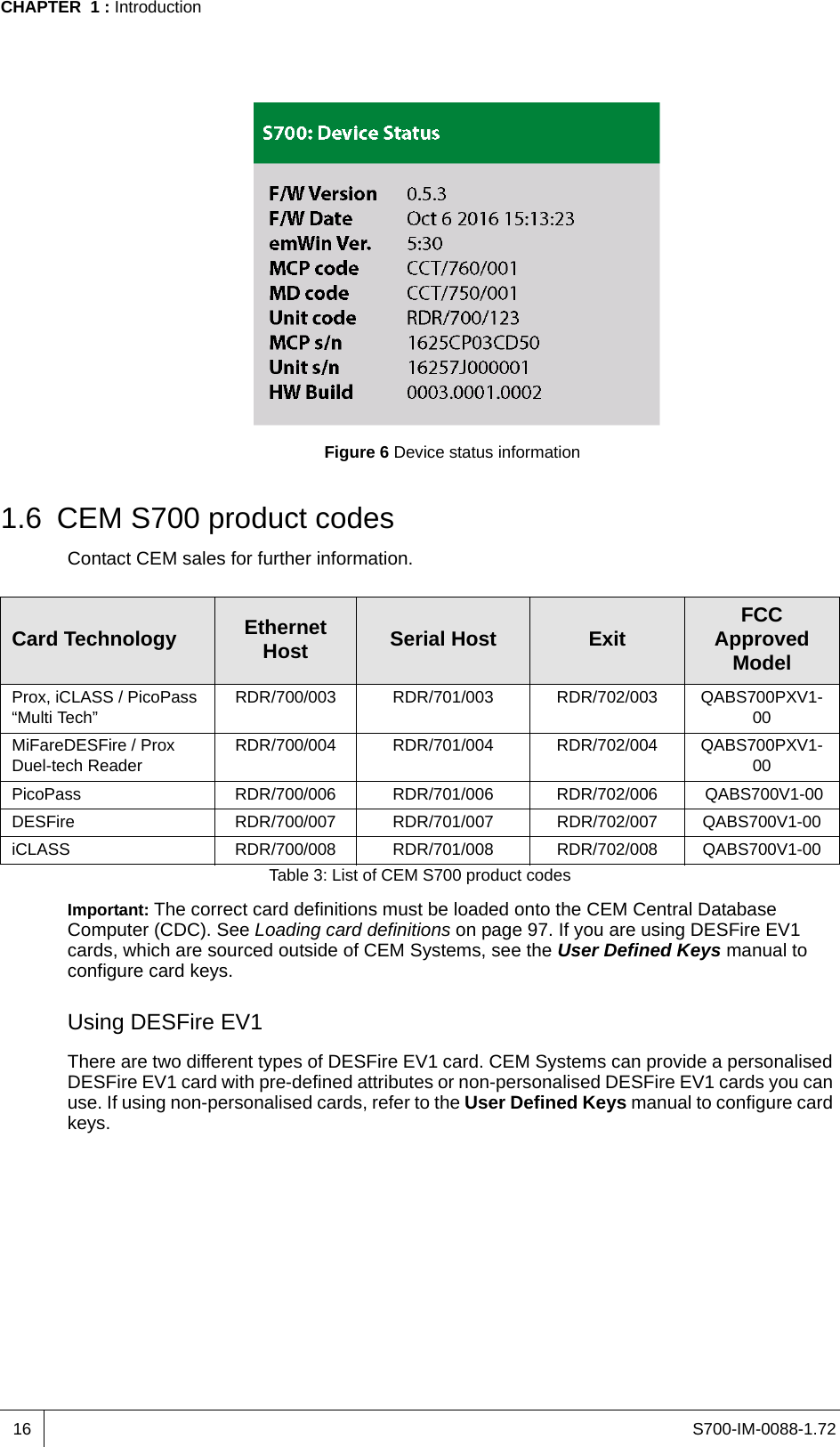
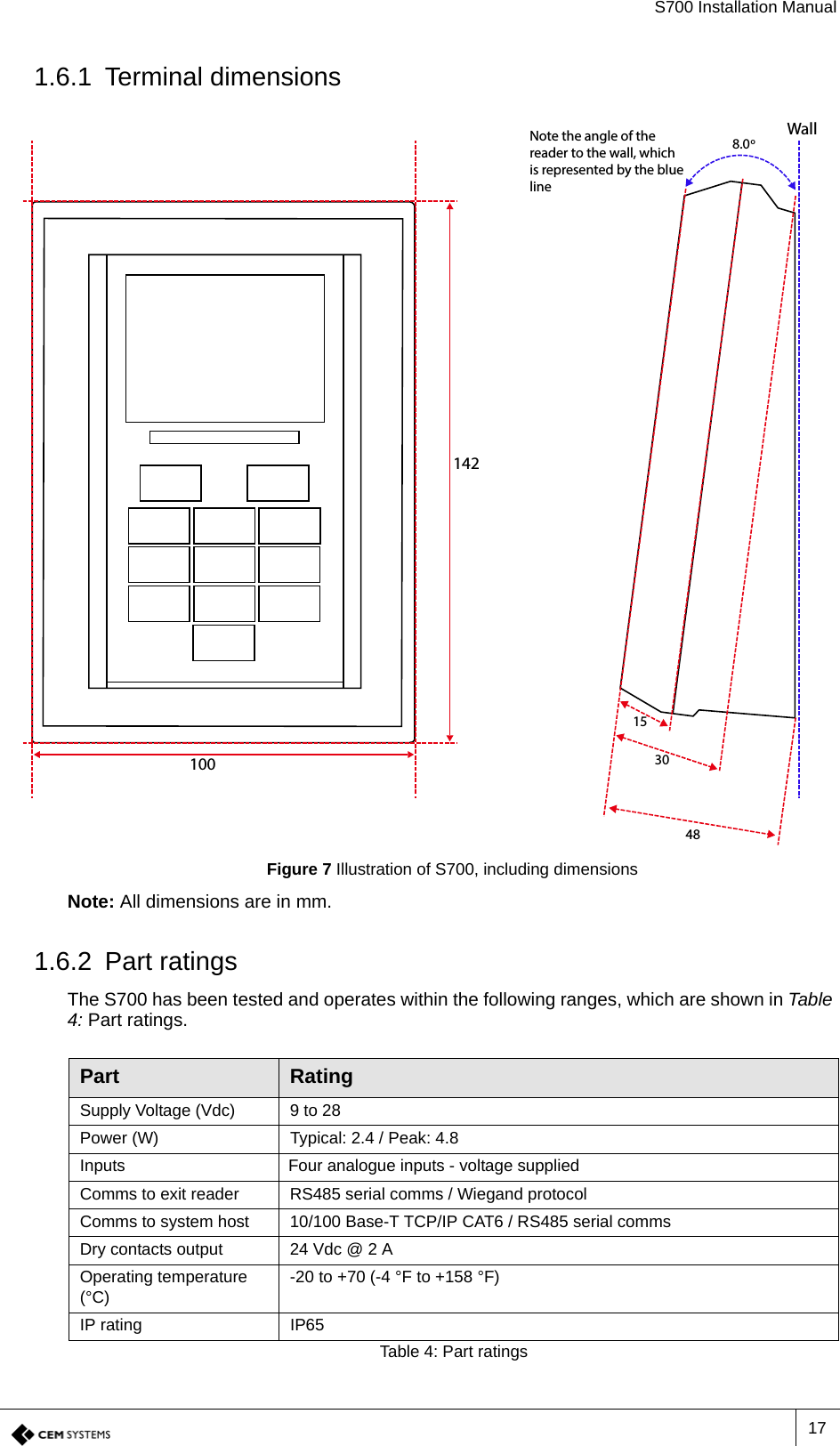
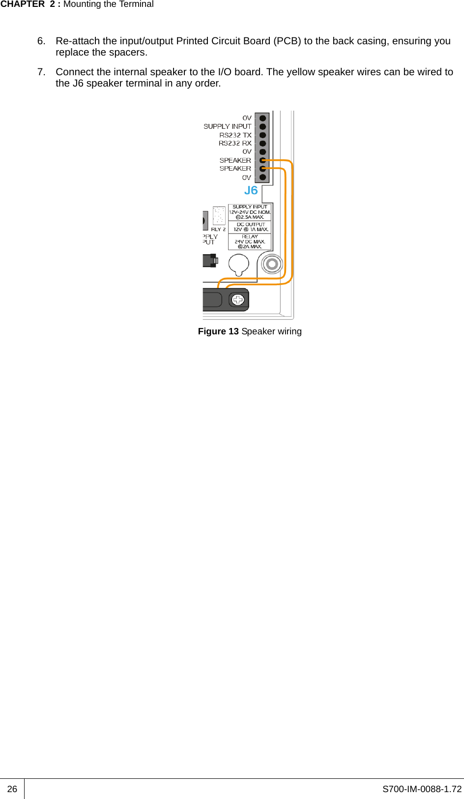
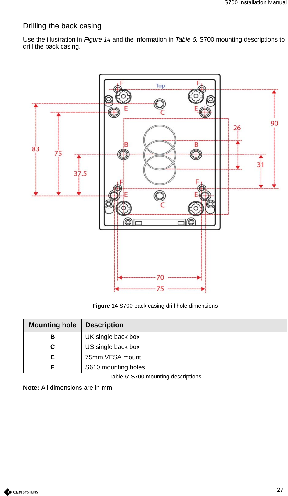
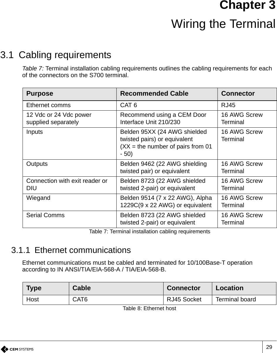
User Manual
2.
Quick start guide
User Manual
Navigation menu
Upload a User Manual
Namespaces
Wiki Guide
HTML
PDF
Info
Views
User Manual
Discussion / Help
Navigation