Controlled Electronic Management Systems S700PXV1-00 S700 multi smart card reader User Manual
Controlled Electronic Management Systems Ltd S700 multi smart card reader
Contents
- 1. User Manual
- 2. Quick start guide
User Manual

S700-IM-0088-1.72
S700
Installation Manual
Notice
The information in this manual was current when published. The manufacturer reserves the right to revise and
improve its products. All specifications are therefore subject to change without notice.
Copyright
Under copyright laws, the contents of this manual may not be copied, photocopied, reproduced, translated or reduced
to any electronic medium or machine-readable form, in whole or in part, without prior written consent of © 2017 Tyco
Security Products. All Rights Reserved.
Trademarks
The trademarks, logos, and service marks displayed on this document are registered in the United States (or other
countries). Any misuse of the trademarks is strictly prohibited and Tyco Security Products will aggressively enforce its
intellectual property rights to the fullest extent of the law, including pursuit of criminal prosecution wherever necessary.
All trademarks not owned by Tyco Security Products are the property of their respective owners, and are used with
permission or allowed under applicable laws.
Product offerings and specifications are subject to change without notice. Actual products may vary from photos. Not
all products include all features. Availability varies by region. Contact your sales representative for more information.
Licence information
Your use of this product is governed by certain terms and conditions.
Support
If you require technical assistance using CEM products, please contact the CEM Support team using the following
telephone number:
Telephone:+44(0)2890 456656
Email: cem.support@tycoint.com
• Please provide our support engineers with as much information as possible. This may include:
• Site name
• Product name and model
• CEM software version
• Description of the problem
Publication Date
February 2017

S700 Installation Manual
3
Warning - For FCC Labelled S700Terminals
This device complies with Part 15 of the FCC rules. Operation is subject to the following two conditions:
(1) This device may not cause harmful interference, and
(2) This device must accept an interference received, including interference that may cause undesired operation.
This equipment complies with FCC radiation exposure limits set forth for an uncontrolled environment. End users must
follow the specific operating instructions for satisfying RF exposure compliance. This transmitter must not be co-
located or operating in conjunction with any other antenna or transmitter.
Changes or modifications not expressly approved by the party responsible for compliance could void the user's
authority to operate the equipment.
Installation of this device shall be performed by a qualified person in accordance to all local regulations.
This system must be installed within the protected premise in accordance with the National Electrical Code (NFPA70),
and the local authorities having jurisdiction.
Equipment changes or modifications without the approval of the party responsible for compliance could void the user's
authority to operate the equipment and could create a hazardous condition.

S700-IM-0088-1.72
4

S700 Installation Manual
5
Chapter 1 Introduction . . . . . . . . . . . . . . . . . . . . . . . . . . . . . . . . . . . . . . 7
Terminal user interface . . . . . . . . . . . . . . . . . . . . . . . . . . . . . . . . . . . . . . . . . . . . . . . . 8
Using the reader . . . . . . . . . . . . . . . . . . . . . . . . . . . . . . . . . . . . . . . . . . . . . . . . . . . . . 8
Presenting your card. . . . . . . . . . . . . . . . . . . . . . . . . . . . . . . . . . . . . . . . . . . . . . . . . 10
Mode-specific response screens. . . . . . . . . . . . . . . . . . . . . . . . . . . . . . . . . . . . . . . . 15
Checking the device status . . . . . . . . . . . . . . . . . . . . . . . . . . . . . . . . . . . . . . . . . . . . 15
CEM S700 product codes . . . . . . . . . . . . . . . . . . . . . . . . . . . . . . . . . . . . . . . . . . . . . 16
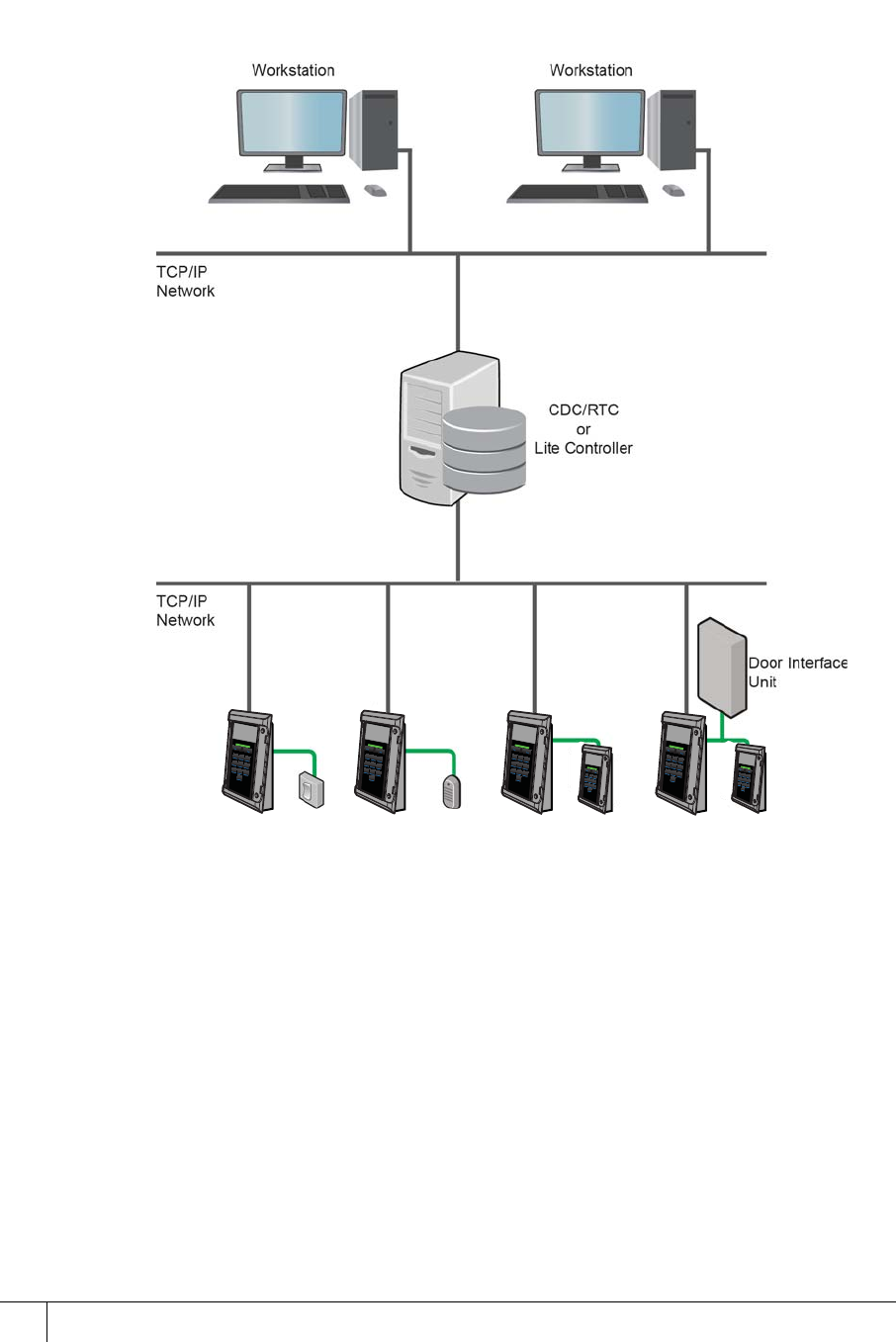
Simplified AC2000 network topology . . . . . . . . . . . . . . . . . . . . . . . . . . . . . . . . . . . . 20
Hardware installation process. . . . . . . . . . . . . . . . . . . . . . . . . . . . . . . . . . . . . . . . . . 21
Chapter 2 Mounting the Terminal. . . . . . . . . . . . . . . . . . . . . . . . . . . . . 23
Preparing for mounting . . . . . . . . . . . . . . . . . . . . . . . . . . . . . . . . . . . . . . . . . . . . . . . 23
Chapter 3 Wiring the Terminal . . . . . . . . . . . . . . . . . . . . . . . . . . . . . . . 29
Cabling requirements . . . . . . . . . . . . . . . . . . . . . . . . . . . . . . . . . . . . . . . . . . . . . . . . 29
The front board . . . . . . . . . . . . . . . . . . . . . . . . . . . . . . . . . . . . . . . . . . . . . . . . . . . . . 30
The input/output board . . . . . . . . . . . . . . . . . . . . . . . . . . . . . . . . . . . . . . . . . . . . . . . 31
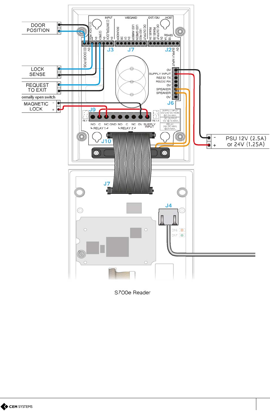
Wiring locks. . . . . . . . . . . . . . . . . . . . . . . . . . . . . . . . . . . . . . . . . . . . . . . . . . . . . . . . 33
Terminal with Request to Exit switch . . . . . . . . . . . . . . . . . . . . . . . . . . . . . . . . . . . . 35
Configuration information . . . . . . . . . . . . . . . . . . . . . . . . . . . . . . . . . . . . . . . . . . . . . 36
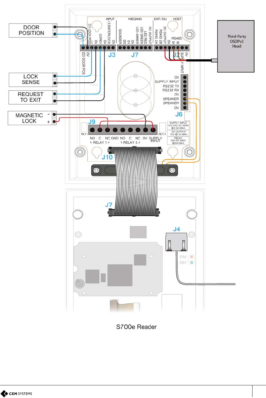
Terminal with third-party OSDPv2 read head . . . . . . . . . . . . . . . . . . . . . . . . . . . . . . 37
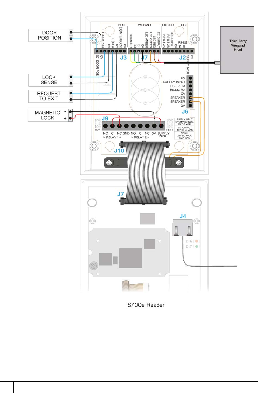
Terminal with third-party Wiegand read head . . . . . . . . . . . . . . . . . . . . . . . . . . . . . . 38
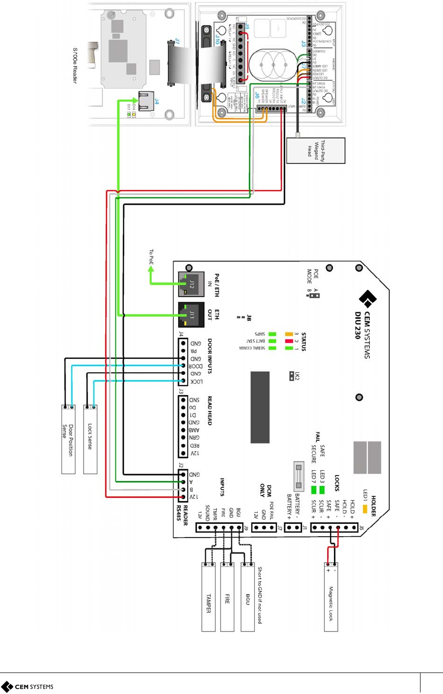
Terminal with DIU 230 and third-party Wiegand read head . . . . . . . . . . . . . . . . . . . 39
Configuration information . . . . . . . . . . . . . . . . . . . . . . . . . . . . . . . . . . . . . . . . . . . . . 40
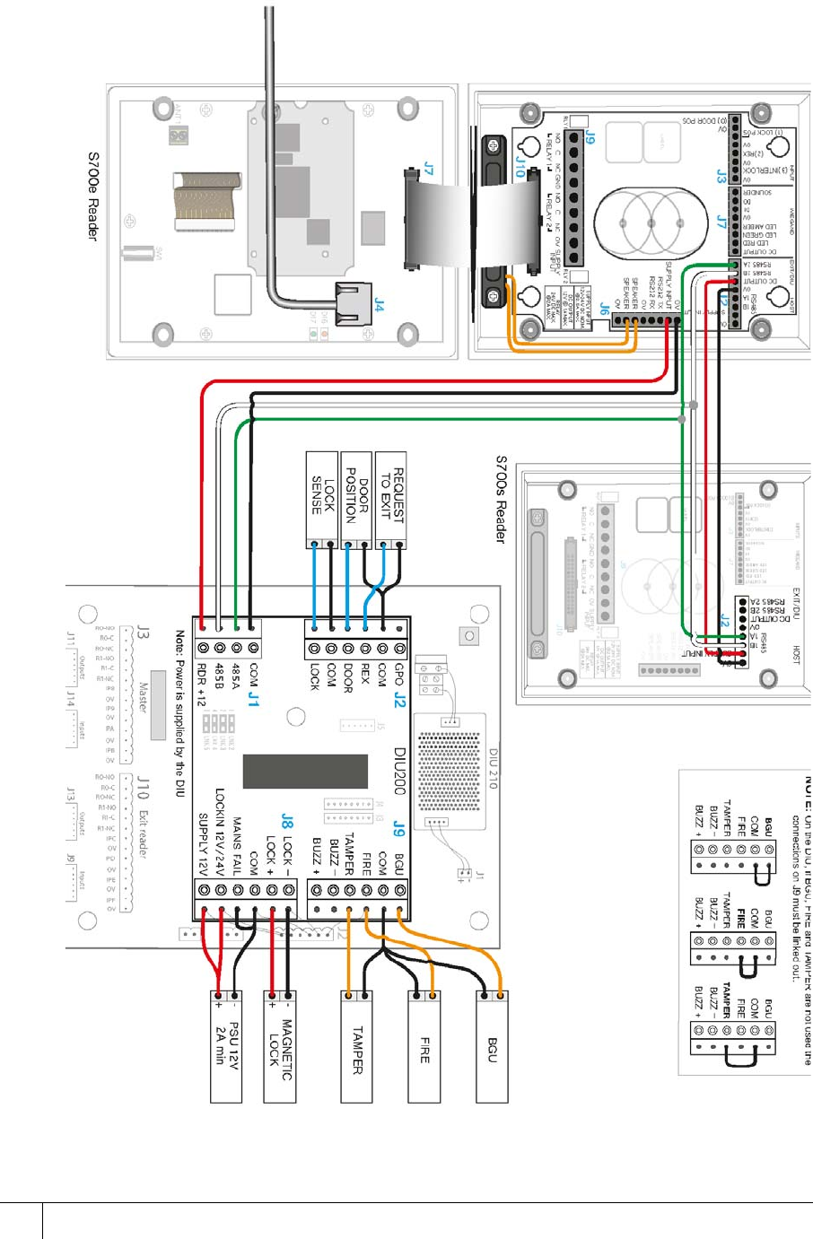
S700e with S700s exit reader . . . . . . . . . . . . . . . . . . . . . . . . . . . . . . . . . . . . . . . . . . 42
S700 with DIU 210 and S700s exit reader . . . . . . . . . . . . . . . . . . . . . . . . . . . . . . . . 44
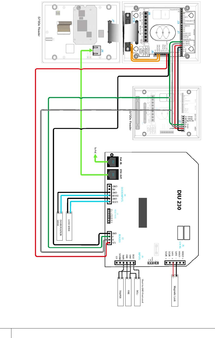
S700 terminal with DIU 230 . . . . . . . . . . . . . . . . . . . . . . . . . . . . . . . . . . . . . . . . . . . 46
Tamper detection on reader inputs . . . . . . . . . . . . . . . . . . . . . . . . . . . . . . . . . . . . . . 48
Chapter 4 Reader Network Configuration . . . . . . . . . . . . . . . . . . . . . . 51
Checking the network status of the S700 . . . . . . . . . . . . . . . . . . . . . . . . . . . . . . . . . 51
Accessing the System Configuration Menu . . . . . . . . . . . . . . . . . . . . . . . . . . . . . . . 52
Chapter 5 AC2000 Software Configuration . . . . . . . . . . . . . . . . . . . . . 55
Reader addressing . . . . . . . . . . . . . . . . . . . . . . . . . . . . . . . . . . . . . . . . . . . . . . . . . . 55
Adding the device to AC2000 . . . . . . . . . . . . . . . . . . . . . . . . . . . . . . . . . . . . . . . . . . 56
Configuring devices. . . . . . . . . . . . . . . . . . . . . . . . . . . . . . . . . . . . . . . . . . . . . . . . . . 58

S700-IM-0088-1.72
6
Next steps . . . . . . . . . . . . . . . . . . . . . . . . . . . . . . . . . . . . . . . . . . . . . . . . . . . . . . . . . 62
Chapter 6 The System Configuration Menu . . . . . . . . . . . . . . . . . . . . 65
Menu overview . . . . . . . . . . . . . . . . . . . . . . . . . . . . . . . . . . . . . . . . . . . . . . . . . . . . . 66
Navigation . . . . . . . . . . . . . . . . . . . . . . . . . . . . . . . . . . . . . . . . . . . . . . . . . . . . . . . . . 66
Accessing the system configuration menu . . . . . . . . . . . . . . . . . . . . . . . . . . . . . . . . 67
Chapter 7 S700 Operational Modes . . . . . . . . . . . . . . . . . . . . . . . . . . . 75
Door mode timings . . . . . . . . . . . . . . . . . . . . . . . . . . . . . . . . . . . . . . . . . . . . . . . . . . 75
Passenger Mode. . . . . . . . . . . . . . . . . . . . . . . . . . . . . . . . . . . . . . . . . . . . . . . . . . . . 79
Interlock. . . . . . . . . . . . . . . . . . . . . . . . . . . . . . . . . . . . . . . . . . . . . . . . . . . . . . . . . . . 82
Equipment mode. . . . . . . . . . . . . . . . . . . . . . . . . . . . . . . . . . . . . . . . . . . . . . . . . . . . 87
Appendix 1 Updating Firmware . . . . . . . . . . . . . . . . . . . . . . . . . . . . . 91
Appendix 2 Broadcast and Timezone Priorities . . . . . . . . . . . . . . . . 95
Appendix 3 Loading card definitions . . . . . . . . . . . . . . . . . . . . . . . . . 97
7
Chapter 1
Introduction
The S700 reader is an access terminal that provides secure door control and access monitoring at the
controlled location.
Used as part of the AC2000 system, the S700 reader controls access to restricted areas while also
giving you a range of information tools and applications at the door.
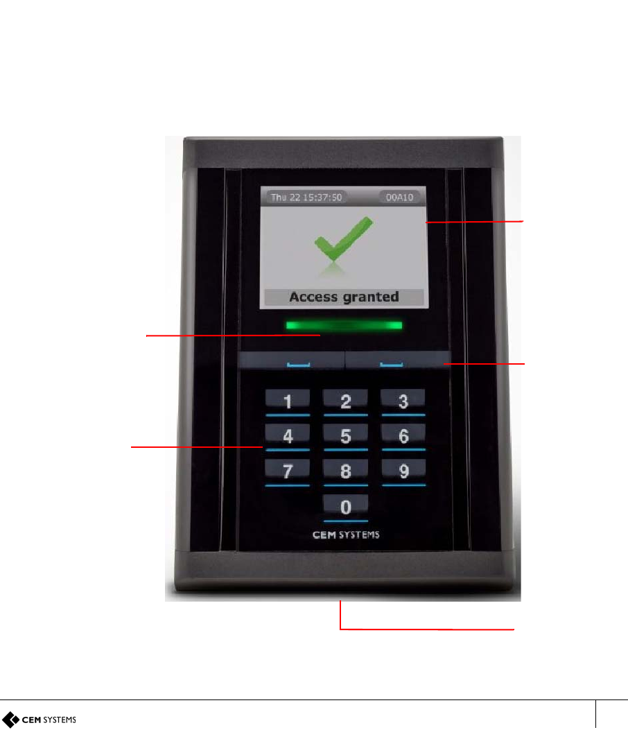
Figure 1 Photograph of the S700 terminal
Multi-colour
2.4 inch QVGA
LCD Screen
Context
status light
Speaker
sensitive
function keys
Capacitive
Keypad
bar
S700-IM-0088-1.72
CHAPTER 1 : Introduction
8
1.1 Terminal user interface
Use the S700 interface to display information and enable user interaction to perform specific
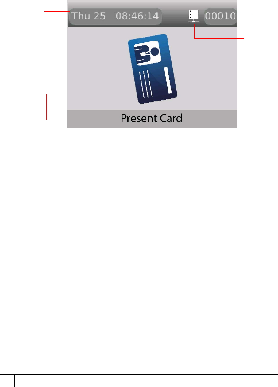
functions. The screen displays the date, time, and the reader system address.
Date and time: The date, time, and day are permanently displayed.
Reader address: The reader address displays a unique five-digit number for each terminal on
the AC2000 system.
Figure 2 Terminal screen
1.2 Using the reader
The S700 is always in one of three modes:
• Door mode
• Free access
• Locked out mode
The home screen displays one of the following modes:
Reader
address
Date and time
display
Information
Network
status
display
indicator
S700 Installation Manual
9
Door state
Figure 3 Door mode
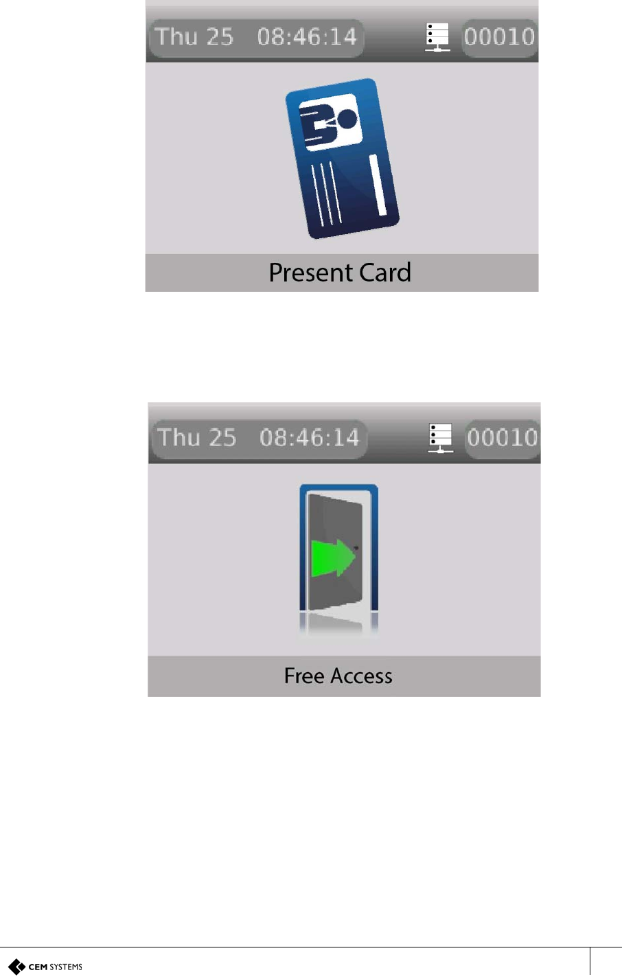
Door mode enables access for all valid cardholders after a card is swiped.
Free access mode
Figure 4 Free access mode
Free access mode means that no card swipe is necessary to gain entry or exit because the
door is unlocked.
S700-IM-0088-1.72
CHAPTER 1 : Introduction
10
Locked out mode
Figure 5 Locked out mode
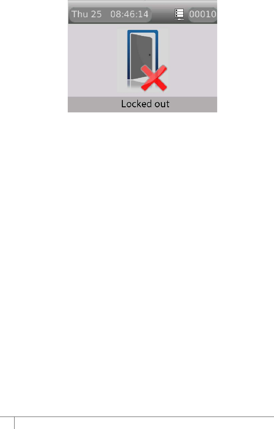
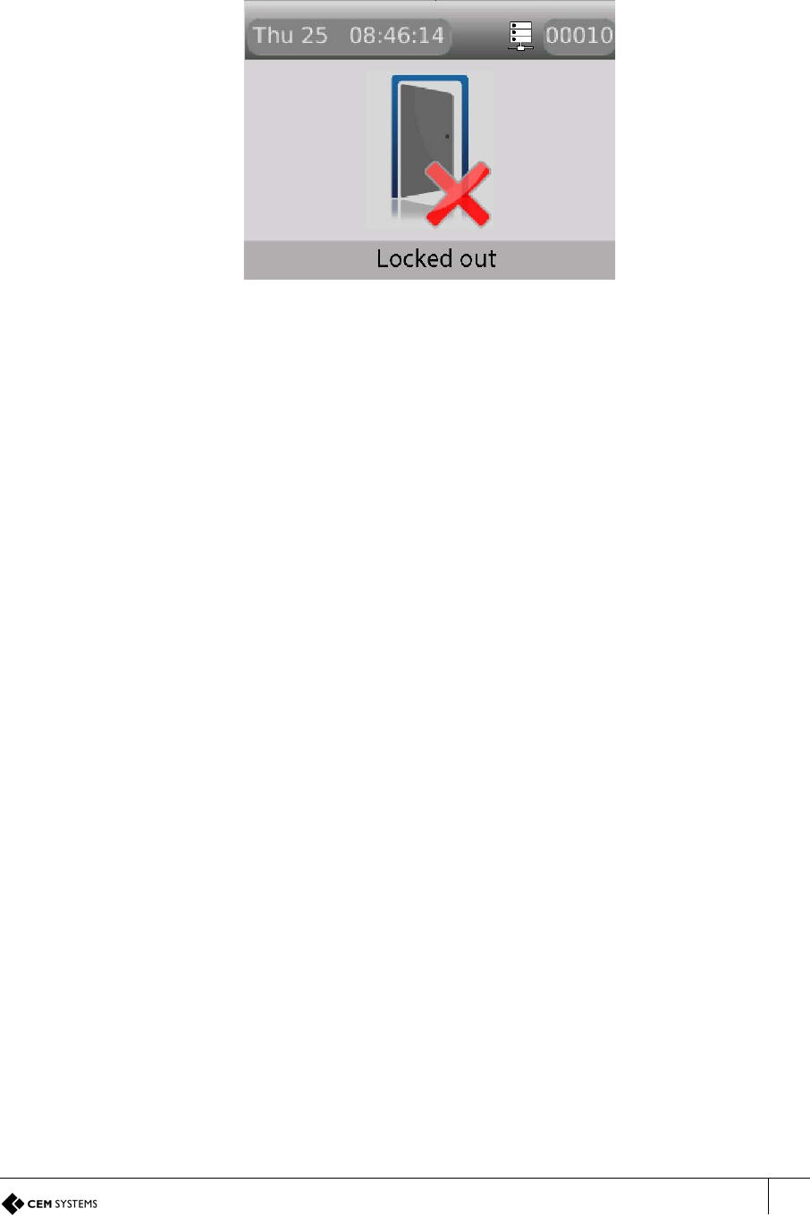
Locked out mode means that the door is locked and no access is permitted.
1.3 Presenting your card
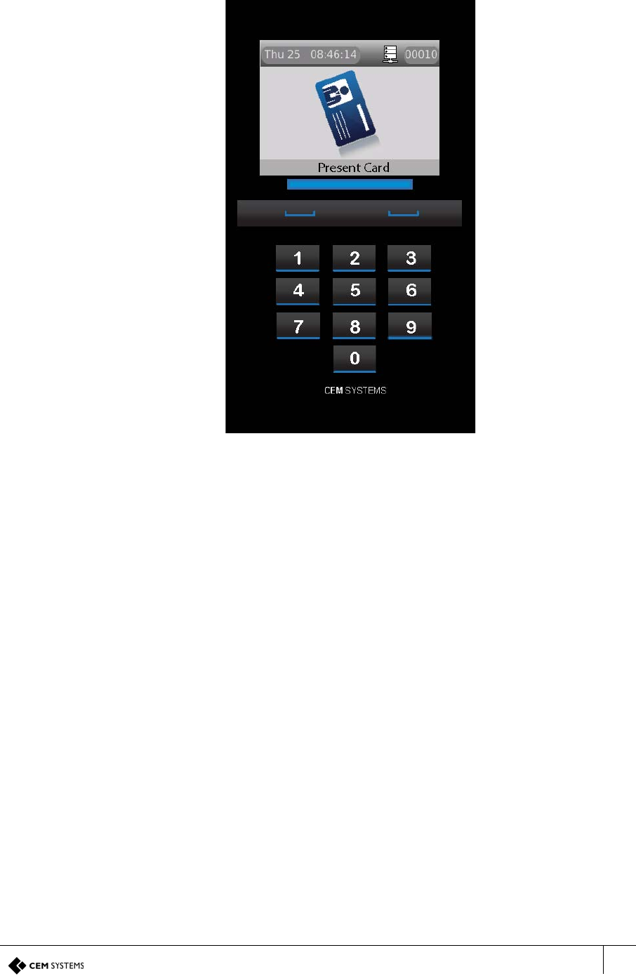
To open a door, present your card to the access control card no more than 3 cm in front of the
terminal. The multi-coloured LCD status of the terminal changes colour and the response
screen displays.
Note: The read range depends on the card technology that is used and the mounting
arrangement of the reader; 3 cm is the minimum read range that can be expected for all cards.
S700 Installation Manual
11
A typical card swipe takes you through the following steps:
1. Home screen: When the terminal is idle, the home screen is displayed.
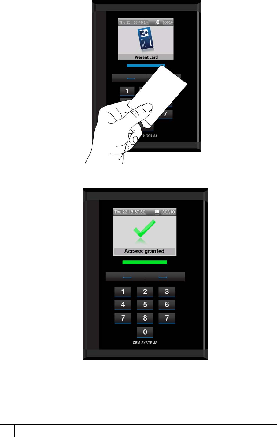
S700-IM-0088-1.72
CHAPTER 1 : Introduction
12
2. Swipe Card: Swipe your card in close proximity to the terminal.
3. Response screen: The response screen appears and access is granted.
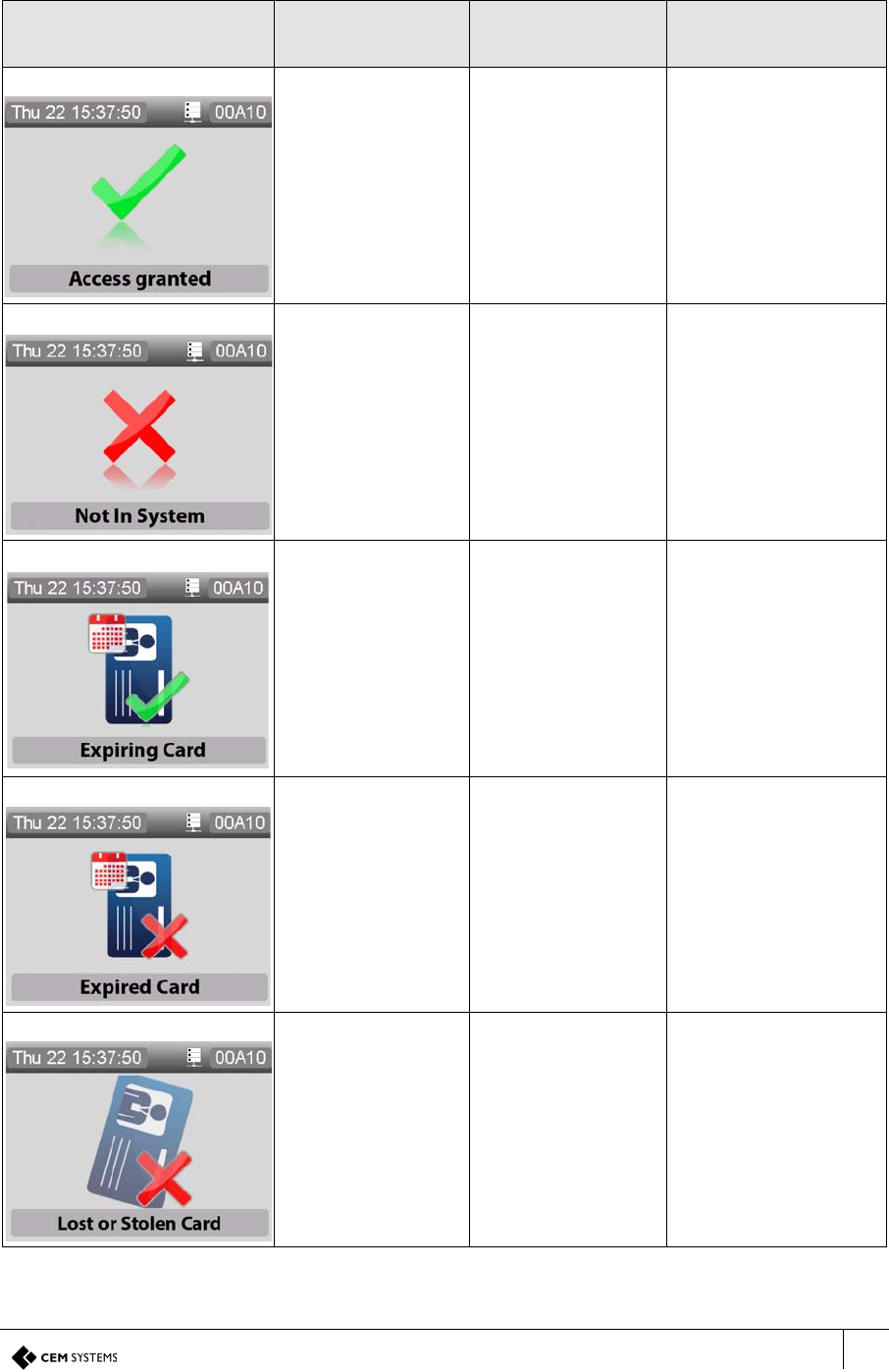
S700 Installation Manual
13
Response Screens
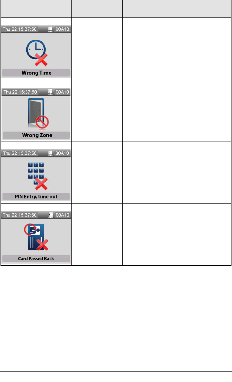
The response screens are described in Table 1: Response Screens for S700:
UI Screen Message Description Multi-colour status
light
Access granted Access is granted Green
Not in system Access is not
granted as card is
not registered on
the system
Red
Expiring Card Access is granted
and your card is set
to expire within 14
days
Green
Expired card Access is not
granted as your
card has expired
Red
Lost or Stolen card Access is not
granted as your
card has been
reported as lost or
stolen
Red
Table 1: Response Screens for S700
S700-IM-0088-1.72
CHAPTER 1 : Introduction
14
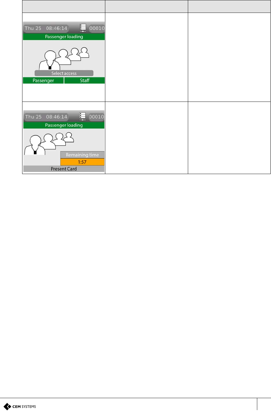
Wrong time Access is not
granted as you are
attempting to gain
access outside the
allocated time
Amber
Wrong zone Access is not
granted as you do
not have
permission to enter
this zone
Amber
PIN Entry, time out Access is not
granted as you
have taken too long
to enter your PIN
Amber
Card passed back Access is not
granted, you must
comply with the
anti-passback site
access policy
Amber
UI Screen Message Description Multi-colour status
light
Table 1: Response Screens for S700
S700 Installation Manual
15
1.4 Mode-specific response screens
Table 2: Mode-specific Response screens describes mode-specific response screens for the
S700.
1.5 Checking the device status
When you have installed the S700 reader, you can use the device to ensure that you have the
correct version number, or confirm the part and serial numbers in the event of a support call.
To check the product codes, part numbers, serial numbers, and build version of the S700
reader, complete the following step:
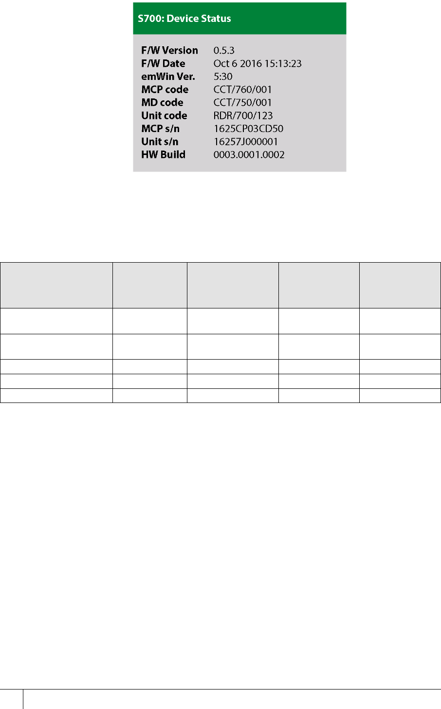
• Tap the left function key quickly at least three times. The S700: Device Status screen
appears showing the device information, as shown in Figure 6.
UI Screen Message Description
Select access: Passenger or
Staff Press Staff or Passenger
for extended or timed
access.
The countdown timer starts
when the door is opened
when Passenger mode is
selected.
Swipe your card to prompt
the user to extend or end the
mode.
Present Card In Passenger mode, the
countdown timer has
started.
To set the time, select the
device and use the
Properties tab in the
Devices application.
Table 2: Mode-specific Response screens
S700-IM-0088-1.72
CHAPTER 1 : Introduction
16
Figure 6 Device status information
1.6 CEM S700 product codes
Contact CEM sales for further information.
Important: The correct card definitions must be loaded onto the CEM Central Database
Computer (CDC). See Loading card definitions on page 97. If you are using DESFire EV1
cards, which are sourced outside of CEM Systems, see the User Defined Keys manual to
configure card keys.
Using DESFire EV1
There are two different types of DESFire EV1 card. CEM Systems can provide a personalised
DESFire EV1 card with pre-defined attributes or non-personalised DESFire EV1 cards you can
use. If using non-personalised cards, refer to the User Defined Keys manual to configure card
keys.
Card Technology Ethernet
Host Serial Host Exit FCC
Approved
Model
Prox, iCLASS / PicoPass
“Multi Tech”
RDR/700/003 RDR/701/003 RDR/702/003 QABS700PXV1-
00
MiFareDESFire / Prox
Duel-tech Reader
RDR/700/004 RDR/701/004 RDR/702/004 QABS700PXV1-
00
PicoPass RDR/700/006 RDR/701/006 RDR/702/006 QABS700V1-00
DESFire RDR/700/007 RDR/701/007 RDR/702/007 QABS700V1-00
iCLASS RDR/700/008 RDR/701/008 RDR/702/008 QABS700V1-00
Table 3: List of CEM S700 product codes
S700 Installation Manual
17
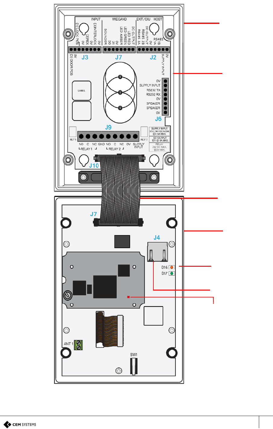
1.6.1 Terminal dimensions
100
142
Wall
8.0o
15
30
48
Note the angle of the
reader to the wall, which
is represented by the blue
line
Figure 7 Illustration of S700, including dimensions
Note: All dimensions are in mm.
1.6.2 Part ratings
The S700 has been tested and operates within the following ranges, which are shown in Table
4: Part ratings.
Part Rating
Supply Voltage (Vdc) 9 to 28
Power (W) Typical: 2.4 / Peak: 4.8
Inputs Four analogue inputs - voltage supplied
Comms to exit reader RS485 serial comms / Wiegand protocol
Comms to system host 10/100 Base-T TCP/IP CAT6 / RS485 serial comms
Dry contacts output 24 Vdc @ 2 A
Operating temperature
(°C)
-20 to +70 (-4 °F to +158 °F)
IP rating IP65
Table 4: Part ratings

S700-IM-0088-1.72
CHAPTER 1 : Introduction
18
1.6.3 Onboard memory
The system memory, 256 Mb RAM, 2 Gb NAND Flash, can hold the following:
• Up to 250,000 cardholder records - offline
• Up to 50,000 transactions - offline
S700 Installation Manual
19
1.6.4 Terminal key component parts
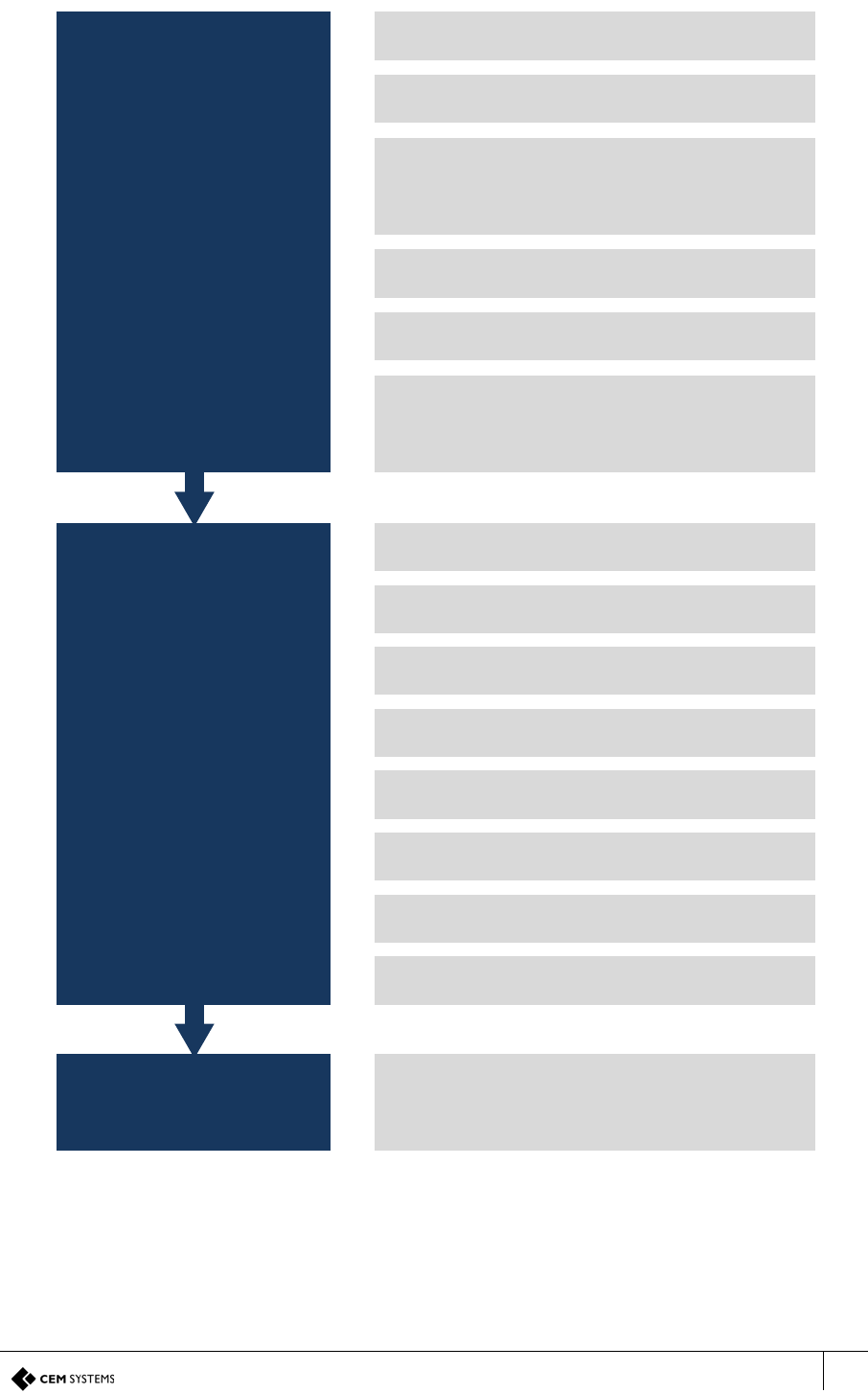
Figure 8 shows the key components of the S700 reader.
Figure 8 Illustration of the key component parts
Back casing
I/O board
Ribbon cable
Front casing
Front board
Back
Front
Operational LED:
This light flashes if
the reader is
operational and
working correctly
RJ45 Ethernet socket
S700 Installation Manual
21
1.8 Hardware installation process
Mounting
the Terminal
Wiring
the Terminal
Network
conguration
Remove screws from the S700 front casing
Disconnect ribbon cable from the back I/O board
If required, remove the I/O board from the back casing
Note: The speaker wires must be temporarily disconnected
Drill holes in the back casing for cable entry and mounting
Mount the terminal back casing to the tted back box or wall
If required, re-t the I/O board
Reconnect the speaker wires if they have been disconnected
Connect the input devices to the I/O board terminals
Connect the lock
If required, connect a third-party exit read head: Wiegand or
OSDP
If required, connect an S700 exit reader and DIU
Connect 12 Vdc or 24 Vdc power to the I/O board
Reconnect the ribbon cable to the I/O board
Connect either the Ethernet or RS485 network cable
Fit the security screws and side panels
Congure terminal network setting
Figure 10 Hardware installation flow chart

S700-IM-0088-1.72
CHAPTER 1 : Introduction
22
23
Chapter 2
Mounting the Terminal
You can mount the S700 terminal on the following standard electrical back boxes:
• UK single back box
• US single back box
• 75mm VESA mount
2.1 Preparing for mounting
Take care with the internal components when you are disassembling the terminal.
2.1.1 Recommended tools
The recommended tools for mounting the terminal are as follows:
• 2.5 mm flat-head screwdriver for input and output connections
• 3 mm flat-head screwdriver for DC power connections
• Wire cutters and strippers
• Security hex screwdriver - size H20
• Pozi-head screwdriver - size PZ1
Product CEM Product Code
Security screw driver handle HTO/000/001
Security screw driver bit HTO/000/000
Table 5: Security screwdriver product codes
S700-IM-0088-1.72
CHAPTER 2 : Mounting the Terminal
24
2.1.2 Opening the terminal
Important: Take care not to strain the ribbon cable connecting the two halves of the terminal.
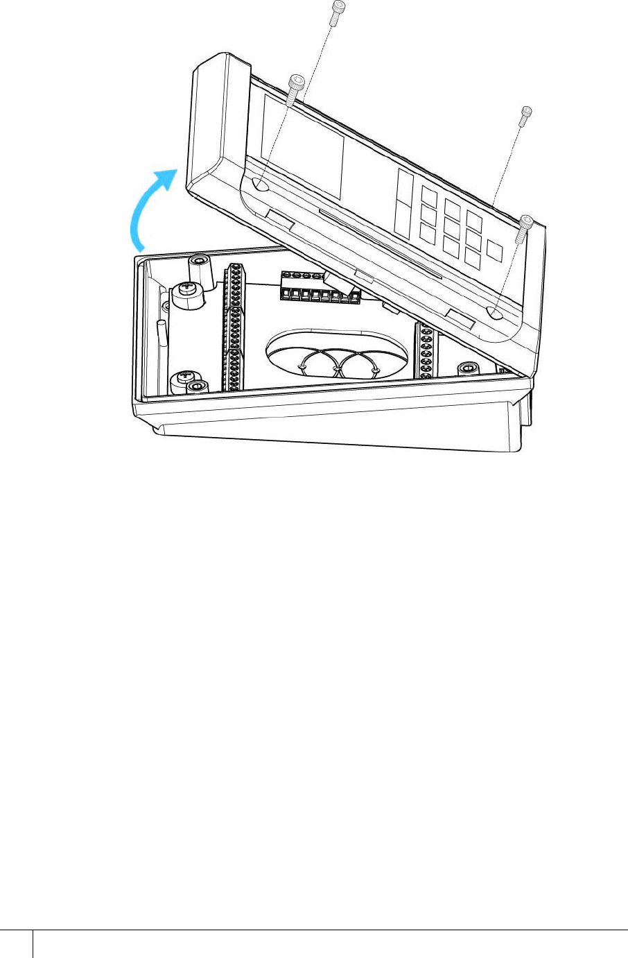
Figure 11 Opening the terminal
To open the terminal, complete the following steps:
1. Set the terminal on a stable, level surface to reduce the risk of the front of the terminal
falling when it is disconnected.
2. Remove the four screws using a security hex screwdriver.
3. Carefully lift the top casing away from the back of the terminal, pivoting as shown in Figure
11 Opening the terminal.
4. Disconnect the ribbon cable from the I/O board before you start wiring.
S700 Installation Manual
25
2.1.3 Mounting the terminal back casing
To access the mounting screw positions of the terminal, the I/O board must first be removed
from the back box.
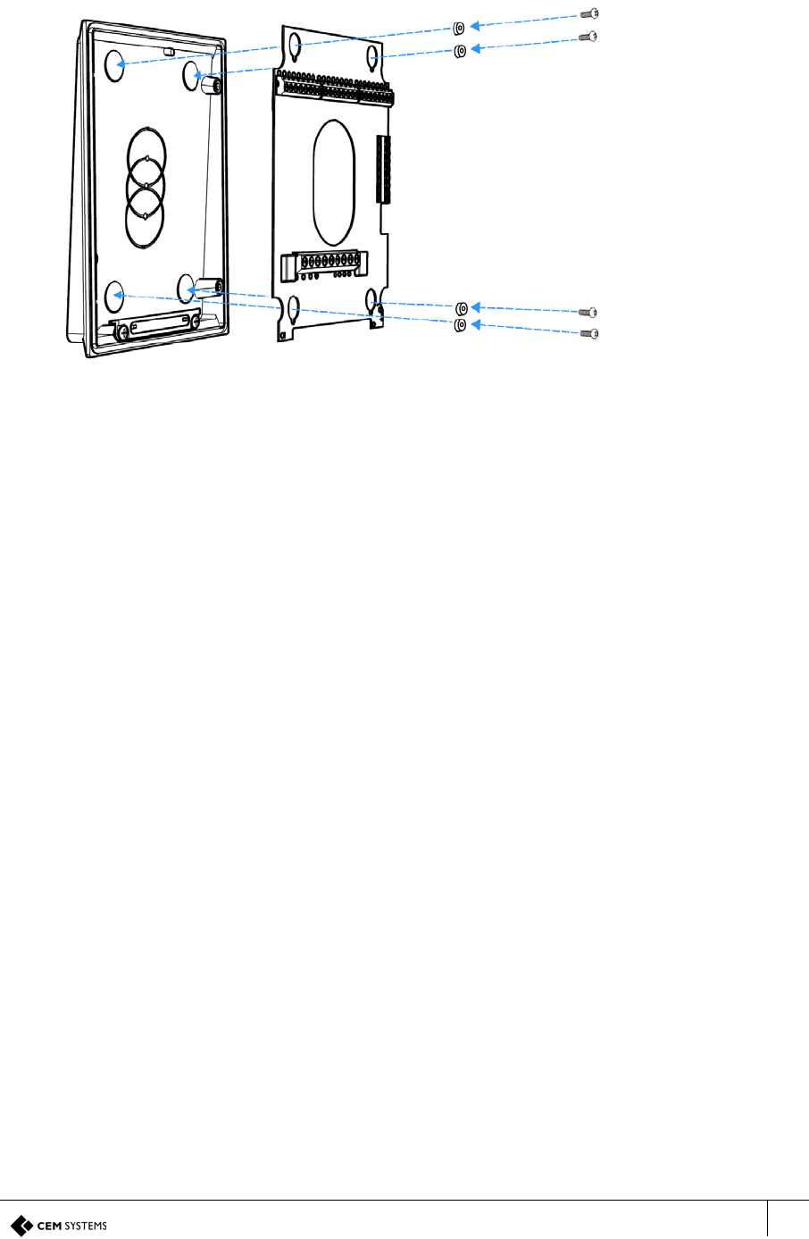
Figure 12 Exploded view illustration of the back casing and I/O board
To mount the terminal back casing, complete the following steps:
1. Remove the four screws and spacers using a Pozi-head screwdriver.
2. Disconnect the two yellow internal speaker wires from connector J6 on the I/O board using
a 2.5 mm screwdriver.
3. Lift the I/O board away from the mountings.
4. Drill the back outer casing as required for cable access and back box mounting. For more
information, see Figure 12.
Important: Ensure that the large case O ring and the 4 small O rings are in place.
5. Fit the back casing to the back box.
AB
CD
CD
A - Back casing
B - I/O board
C - Spacers
D - Screws
S700-IM-0088-1.72
CHAPTER 2 : Mounting the Terminal
26
6. Re-attach the input/output Printed Circuit Board (PCB) to the back casing, ensuring you
replace the spacers.
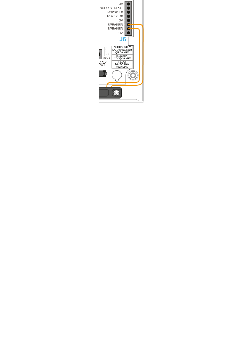
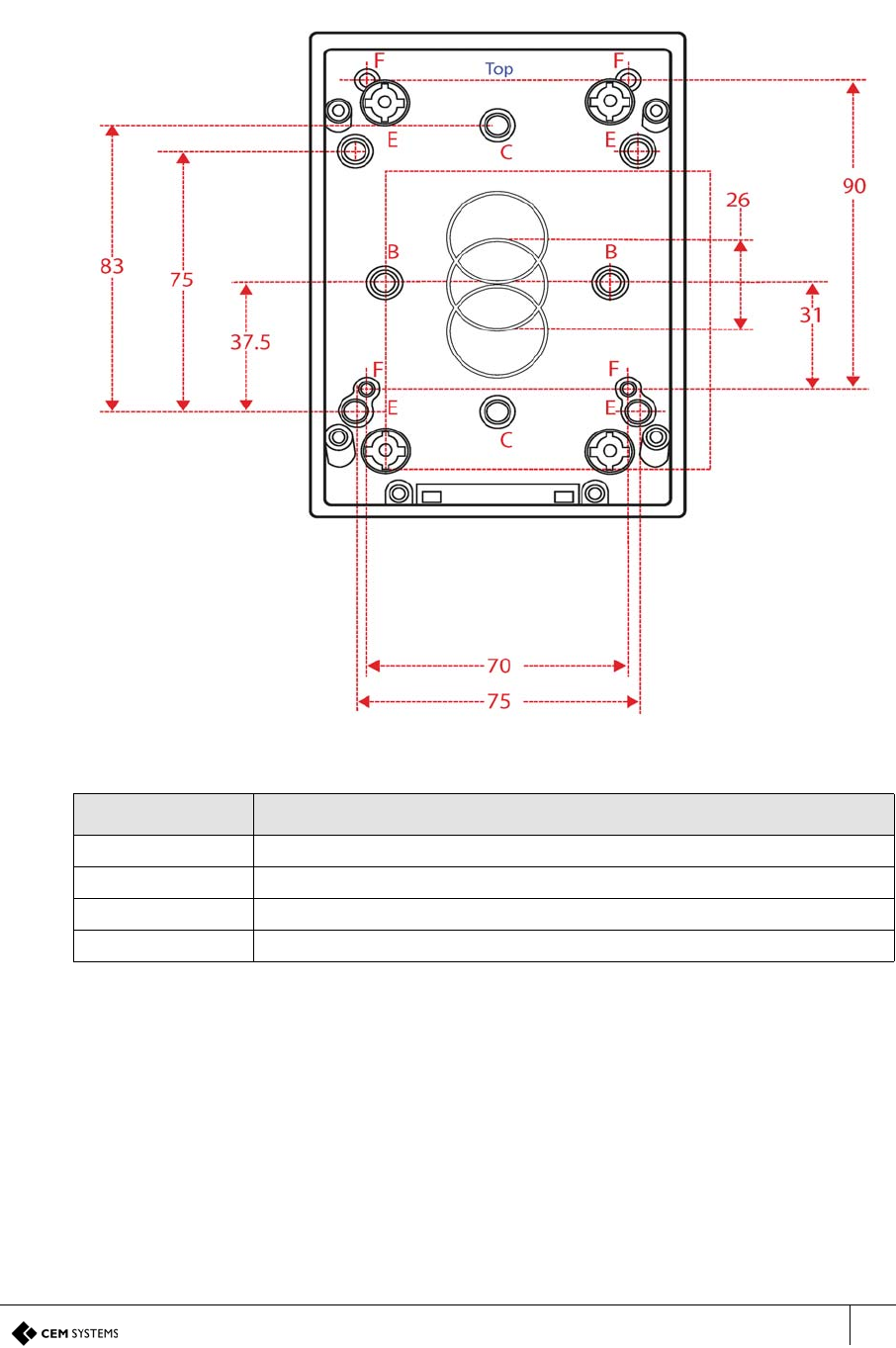
7. Connect the internal speaker to the I/O board. The yellow speaker wires can be wired to
the J6 speaker terminal in any order.
Figure 13 Speaker wiring
S700 Installation Manual
27
Drilling the back casing
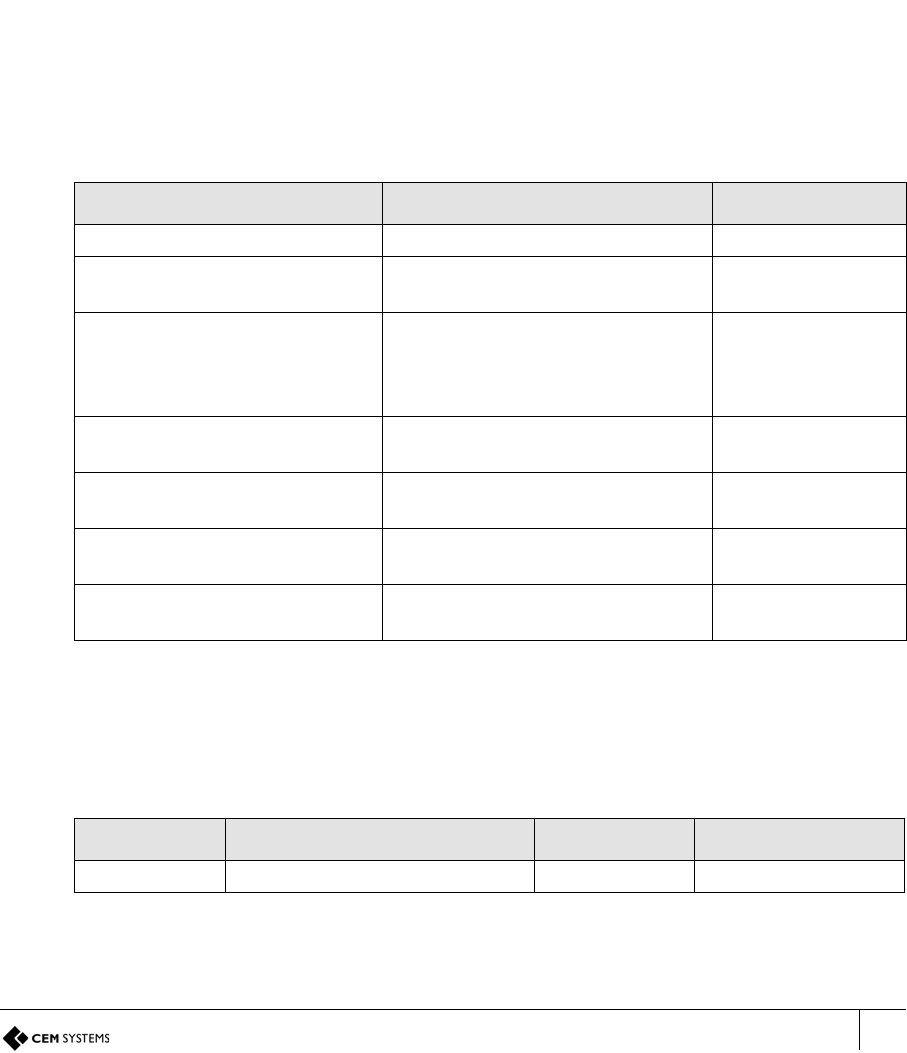
Use the illustration in Figure 14 and the information in Table 6: S700 mounting descriptions to
drill the back casing.
Figure 14 S700 back casing drill hole dimensions
Note: All dimensions are in mm.
Mounting hole Description
BUK single back box
CUS single back box
E75mm VESA mount
FS610 mounting holes
Table 6: S700 mounting descriptions

S700-IM-0088-1.72
CHAPTER 2 : Mounting the Terminal
28
29
Chapter 3
Wiring the Terminal
3.1 Cabling requirements
Table 7: Terminal installation cabling requirements outlines the cabling requirements for each
of the connectors on the S700 terminal.
3.1.1 Ethernet communications
Ethernet communications must be cabled and terminated for 10/100Base-T operation
according to IN ANSI/TIA/EIA-568-A / TIA/EIA-568-B.
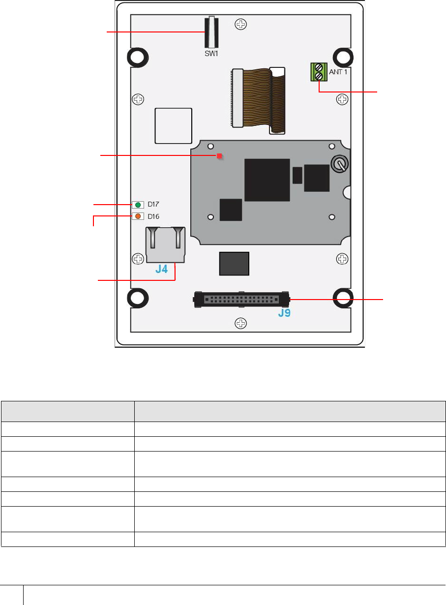
Purpose Recommended Cable Connector
Ethernet comms CAT 6 RJ45
12 Vdc or 24 Vdc power
supplied separately Recommend using a CEM Door
Interface Unit 210/230 16 AWG Screw
Terminal
Inputs Belden 95XX (24 AWG shielded
twisted pairs) or equivalent
(XX = the number of pairs from 01
- 50)
16 AWG Screw
Terminal
Outputs Belden 9462 (22 AWG shielding
twisted pair) or equivalent 16 AWG Screw
Terminal
Connection with exit reader or
DIU Belden 8723 (22 AWG shielded
twisted 2-pair) or equivalent 16 AWG Screw
Terminal
Wiegand Belden 9514 (7 x 22 AWG), Alpha
1229C(9 x 22 AWG) or equivalent 16 AWG Screw
Terminal
Serial Comms Belden 8723 (22 AWG shielded
twisted 2-pair) or equivalent 16 AWG Screw
Terminal
Table 7: Terminal installation cabling requirements
Type Cable Connector Location
Host CAT6 RJ45 Socket Terminal board
Table 8: Ethernet host
S700-IM-0088-1.72
CHAPTER 3 : Wiring the Terminal
30
There must be enough spare cable left within the enclosure/back box to allow a service
engineer to open the terminal case without straining the RJ45 connector. If the cable is subject
to movement or vibration, stranded ethernet cable, and appropriate connectors, must be used.
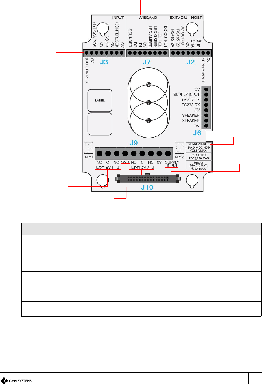
3.2 The front board
The front PCB contains the main electronic components of the reader; it is also where ethernet
communications must be connected.
Figure 15 Illustration of the front board
Tamper Switch
Antenna
connector
(DO NOT
DISTURB)
Network link
speed LED
Ethernet
activity LED
RJ45
connector Ribbon
connector to
the I/O board
Operational
LED
Component Description
RJ45 connector Used for Ethernet communications
Ribbon connector Connects the front PCB to the I/O PCB
Antenna Connector This is used for the PROX antenna. If fitted, DO NOT remove or tamper with
the wires from this connector
Operational LED This light flashes if the reader is operational and working correctly
Ethernet activity LED Flashing green indicates Ethernet activity
Network link LED Orange indicates 100Base-T connection speed - unlit indicates 10Base-T
connection speed
Tamper switch Used to trigger an alarm when the case is opened
Table 9: Description of front board components
S700 Installation Manual
31
3.3 The input/output board
The input/output board provides the connections points for terminal power, inputs, outputs,
third-party Wiegand read heads, communications with exit readers, and Door Interface Units
(DIUs).
Figure 16 Illustration of the Input/Output board
Component Description
Wiegand interface Interface for third-party exit heads using Wiegand protocol
Supply Input and
Speaker Connector
12 Vdc or 24 Vdc power, either from a CEM Door Interface Unit (DIU) or
an appropriate power source must be supplied to this connector
This is also the audio output for the internal speaker.
Output 0 Lock output, either 12 Vdc or 24 Vdc: voltage provided to relay common
connection can be taken internally through the J9 Supply Input terminal or
externally
Ribbon connector Connects the I/O PCB to the front PCB
Output 1 Spare output. This output is also used when configuring the reader in
interlock mode.
Table 10: Description of I/O board components
Input
connector
Wiegand read head
interface
Comms to exit/
DIU or Comms
to Host
Supply Input
and Speaker
Output 0
Ribbon connector
Connector
Safety GND Output 1
Supply Input
Current
(spare)
(lock)
12 Vdc / 24 Vdc
Supply Input

S700-IM-0088-1.72
CHAPTER 3 : Wiring the Terminal
32
Note:
Supply Input Current:
The power requirement of 2.5 A is based on the following:
Host reader peak current @ 12 Vdc = 450 mA
Exit reader peak current @ 12 Vdc = 450 mA
Fully loaded DC output @ 12 Vdc = 1.6 A
Total = 2.5 A
This does not include anything that is connected to the DC Output.
DC Output Current:
The maximum guaranteed current that can be supplied from the 12 Vdc output.
Relay:
Nominal voltage and current that can safely be applied to the relay.
Comms to exit/DIU or
Comms to Host
If this unit is configured as a serial host reader, ‘HOST’ can be used as an
RS485 connection to the network.
If serial communications to a CEM product, such as the S700 or DIU, is
required, the ‘EXIT/DIU’ connection can be used as the connection to the
DIU or exit reader.
If the unit is configured as an exit reader ‘HOST’ can be used as a
connection to the host.
Input connectors Connection points for monitored inputs such as door position, lock sense
and Request to Exit switches.
Component Description
Table 10: Description of I/O board components
S700 Installation Manual
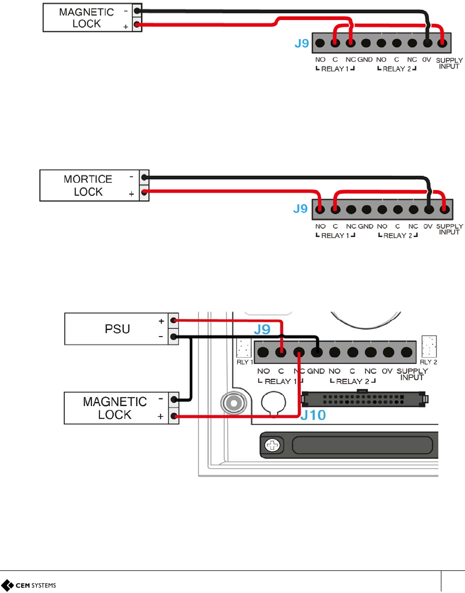
33
3.4 Wiring locks
The terminal supports lock types rated up to 24 Vdc at 2 A max current.
3.4.1 Wiring an internal voltage powered lock
It is possible to connect locks in a fail-safe or fail-secure configuration.
Fail-safe lock
If the terminal loses power, a fail-safe lock opens, allowing free access. Therefore, a lock that
is constantly powered, such as a maglock, must be used.
Figure 17 Magnetic lock
Fail-secure lock
In fail-secure configuration, if the terminal loses power, the lock remains closed. A lock that
requires power to open, such as a mortice lock, must be used.
Figure 18 Mortice Lock
3.4.2 Wiring an external voltage powered lock
Figure 19 Illustration of wiring for lock with external power provided
When you use an external voltage supply to power the lock the power supply ground should be
connected to GND on the I/O board and not 0V.
Note: All connections labelled 0V link to the same circuit.

S700-IM-0088-1.72
CHAPTER 3 : Wiring the Terminal
34
3.4.3 Inputs not in use
Some inputs must be linked out when not in use, to allow the door control to operate and
prevent alarms being generated on the AC2000 system.
This is particularly important for DIU inputs.
These inputs are outlined in the following list:
• Input 0 - door position sensor on terminal I/O board
• Fire input on a DIU
• Tamper input on a DIU
• Break Glass input on a Door Interface Unit
S700-IM-0088-1.72
CHAPTER 3 : Wiring the Terminal
36
3.6 Configuration information
Wiring an S700 terminal with a Request to Exit switch is a basic wiring configuration and is not
recommended for use on high security doors.
Input configuration
Table 11: S700 and Request to Exit switch input configuration illustrates the configuration and
operation of the inputs on the terminal when it is configured with a Request to Exit switch.
Note: Wiring diagram is for the installation of the S700 terminal in Door Mode.
Input number Input function Default input trigger state change
0 Door position short => open
1 Lock position short => open
2 Request to exit switch open => momentary short => open
3 Spare/Interlock short => open
Table 11: S700 and Request to Exit switch input configuration

S700-IM-0088-1.72
CHAPTER 3 : Wiring the Terminal
40
Note: To configure an exit reader as the master reader, see Configuring a Third-Party Reader
as a Master on page 85.
Important: For regulatory compliance, the drain wire must be disconnected at the reader-end of
the cable.
Table 12: Configuration and operation of terminal inputs contains the details for the
configuration and operation of terminal inputs when configured with third-party Wiegand read
heads.
Table 12: Configuration and operation of terminal inputs
Important: If fire and break glass units are not required, the inputs must be connected to GND
to ensure that the DIU functions normally. The tamper input must also be connected to the
GND when it is not in use to prevent alarms being generated on AC2000.
3.9.1 Software configuration for terminal with DIU 230 and third-party
Wiegand read head
To configure AC2000 for use with the terminal, a DIU 230 and a third-party Wiegand read
head, complete the following steps:
1. Add the device in the Devices application as S700+DIU+Slave. For more information on
the procedure for adding a device, see Adding the device to AC2000 on page 56.
2. Enable the third-party read head. For more information on the procedure for enabling a
third-party read head, see Configuring a third-party read head on page 57.
3.10 Configuration information
The S700 terminal facilitates the use of a third-party exit Wiegand head with three LEDs.
Supported third-party read heads
CEM support the use of HID R10 heads for reading Mifare and iClass cards.
Input
number Input location Input function Default input trigger state function
0 DIU Door position short => open
1 DIU Lock position short => open
2 DIU Request to exit switch open => momentary short => open
3 DIU Fire short => open
4 DIU Breakglass short => open
5 DIU Mains power fail Internally triggered
6 DIU Battery low Internally triggered
7 DIU DIU tamper short => open
8 Master terminal Spare short => open
9 Master terminal Spare short => open
A Master terminal Spare short => open
B Master terminal Spare/Interlock short => open
S700 Installation Manual
41
Typical Wiegand read head wiring
For specific read head wiring, consult the third-party manufacturer.
Important: For regulatory compliance, the drain wire must be disconnected at the reader-end of
the cable.
Input configuration
Table 15: S700 and third-party read head input configuration illustrates the configuration and
operation of the inputs on the terminal when configured with a third-party Wiegand read head.
Product CEM Product Code
HID iClass SE R10 SmartCard Reader HDS/053/010
HID iClass SE R30 SmartCard Reader HDS/053/030
HID iClass SE R40 SmartCard Reader HDS/053/040
Table 13: Read head product code
I/O board connection Typical HID colour
GND Black
Sounder Yellow
Green LED Orange
Amber LED Not fitted
Red LED Brown
Data 1 White
Data 0 Green
Head 12V Red
Table 14: Typical Wiegand head wiring
Input number Input function Default input trigger state change
0 Door position short => open
1 Lock position short => open
2 Request to exit switch open => momentary short => open
3 Spare / Interlock short => open
Table 15: S700 and third-party read head input configuration
S700-IM-0088-1.72
CHAPTER 3 : Wiring the Terminal
42
3.11 S700e with S700s exit reader
Figure 24 S700e with S700s exit reader
S700 Installation Manual
43
3.11.1 Configuration information
Using an S700 exit reader provides a higher level of security at the door than using a third-
party read head.
Input configuration
The S700 reader has four inputs and two relay outputs, which are spare in this configuration.
Product CEM Product Code
S700 Card Reader (DESfire) RDR/702/007
S700 Card Reader (iCLASS) RDR/702/008
S700 Card Reader (Pico Pass) RDR/702/006
Table 16: S700 product codes
Input
number Input
location Input function Default input trigger state change
0Master
terminal Door position short => open
1Master
terminal Lock position short => open
2Master
terminal Request to exit switch open => momentary short => open
3Master
terminal Spare / Interlock short => open
4 S700s exit Spare normally open
5 S700s exit Spare normally open
6 S700s exit Spare normally open
7 S700s exit Spare normally open
Table 17: S700e with S700s exit reader input configuration
S700 Installation Manual
45
3.12.1 Configuration information
Using a CEM DIU 210 provides the highest level of security at a door, removing power for the
lock and input monitoring away from the door reader.
Important: The DIU210 uses mains electricity and must only be installed by qualified
personnel.
Input configuration
When a DIU210 is used with a terminal, the DIU controls the main CEM reserved inputs and
the inputs on the readers become spare. The exception to this is input three on the terminal,
input B in Table 7 on page 29, which maintains its status as being used for interlock mode.
Important: If fire and break glass units are not required, the inputs must be connected to GND
to ensure that the DIU functions normally. The tamper input must also be connected to GND
when not in use to prevent alarms being generated on AC2000.
Product CEM Product Code
DIU 200 (Compact board only DIU module) DIU/700/200
DIU 210 Full DIU incl Enclosure/PSU (Does
not include backup batteries) DIU/700/210
Table 18: Door Interface Units product code
Input
number Input
location Input function Default input trigger state change
0 DIU Door position short => open
1 DIU Lock position short => open
2 DIU Request to exit switch open => momentary short => open
3 DIU Break glass short => open
4 DIU Fire short => open
5 DIU Mains power fail Internally triggered
6 DIU Battery low Internally triggered
7 DIU DIU tamper short => open
8Master
terminal Spare short => open
9Master
terminal Spare short => open
AMaster
terminal Spare short => open
BMaster
terminal Spare / Interlock short => open
C Exit reader Spare normally open
D Exit reader Spare normally open
E Exit reader Spare normally open
F Exit reader Spare normally open
Table 19: S700 and DIU210 input configuration
S700 Installation Manual
47
3.13.1 Configuration information
Using a CEM DIU230 also provides the highest level of security at a door, removing power for
the lock and input monitoring away from the door reader. The DIU is a PoE+ device and does
not require specialist electrical qualifications to install.
Input configuration
When a DIU230 is used with an S700 terminal, the DIU controls the main CEM reserved inputs
and the inputs on the readers become spare. The exception to this is input three on the S700
terminal, input B in the Table 21: S700 and DIU230 input configuration, which maintains its
status as being used for interlock mode..
Important: If fire and break glass units are not required, the inputs must be connected to GND
to ensure that the DIU functions normally. The tamper input must also be connected to GND
when it is not in use to prevent alarms being generated on the AC2000 system.
Product CEM Product Code
DIU 230 PoE+ (board only) DIU/700/230
DIU 230 PoE+ (with enclosure) DIU/700/231
Table 20: DIU230 product codes
Input
number Input
location Input function Default input trigger state change
0 DIU Door position short => open
1 DIU Lock position short => open
2 DIU Request to Exit switch open => momentary short => open
3 DIU Fire short => open
4 DIU Breakglass short => open
5 DIU Mains power fail Internally triggered
6 DIU Battery low Internally triggered
7 DIU DIU tamper short => open
8Master
terminal Spare short => open
9Master
terminal Spare short => open
AMaster
terminal Spare short => open
BMaster
terminal Spare / Interlock short => open
C Exit reader Spare normally open
D Exit reader Spare normally open
E Exit reader Spare normally open
F Exit reader Spare normally open
Table 21: S700 and DIU230 input configuration
S700-IM-0088-1.72
48
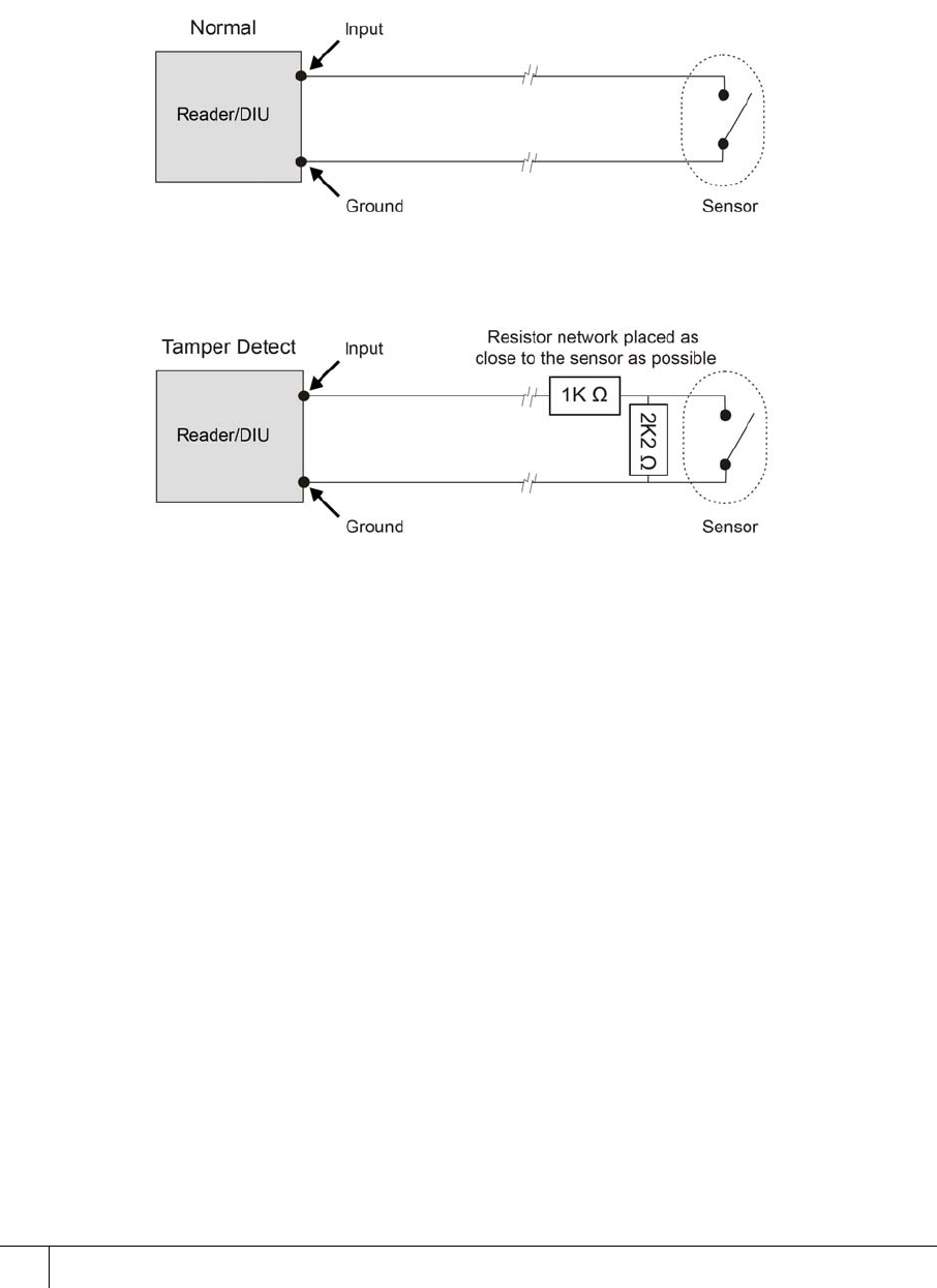
3.14 Tamper detection on reader inputs
Terminal inputs can be monitored for 4-state tampering, open, close, tamper short, and tamper
cut. If an input is tampered with, an alarm is triggered in the AC2000 software. The alarm is a
universal tamper alarm and does not distinguish between the four different states. To monitor
inputs for tamper short and tamper cut, a resistor network must be installed on the input sensor
wiring and the AC2000 software configured to monitor the input.
3.14.1 Wiring the resistor network
Figure 27 Illustration of the resistor network for four state tamper detection on inputs
Important: It is imperative that the tamper resistor network is wired as close to the sensor as
possible.
3.14.2 Configuring software for tamper detection
To configure software for tamper detection, complete the following steps:
1. From the AC2000 Floatbar, click Device Configuration, and click Devices.
2. Select the device on which inputs are to be configured for 4-state tamper detection.
3. Select the Configuration tab.
4. Select the Input Config tab.
5. Select each input element to be configured for four state and tick the 4 state check box.
6. Click Save.

S700 Installation Manual
49
3.14.3 Re-assembling the terminal
To re-assemble the terminal, complete the following steps:
1. Ensure that there is adequate cable length available to reach the connectors comfortably
for each of the following:
– 12 or 24 Vdc
– CAT6 cable for communications
– Output wiring for lock
– Wiring for inputs, for example, door position sensor, lock sense
Important: To maintain the IP65 rating of the terminal, the cable access hole must be
adequately sealed before completing the installation process.
Note: Ensure the speaker is connected.
2. Attach the front pane of the terminal using the ribbon connector.
3. Attach the front of the terminal to the back casing and fix in places with the screws.
4. Attach the protective side panels to the terminal.
Note: If the terminal needs to be opened after installation, the side panels can be removed by
inserting an access card into the slot under the centre of the panel and sliding along the length
of the panel.

S700-IM-0088-1.72
CHAPTER 3 : Wiring the Terminal
50
51
Chapter 4
Reader Network Configuration
The network settings are accessed using the installer configuration menu on the terminal.
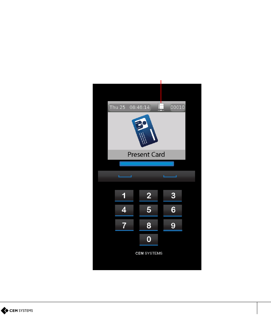
4.1 Checking the network status of the S700
The network status is continuously displayed on the home screen of the reader.
Figure 28 Checking the network status
Network status indicator
S700-IM-0088-1.72
CHAPTER 4 : Reader Network Configuration
52
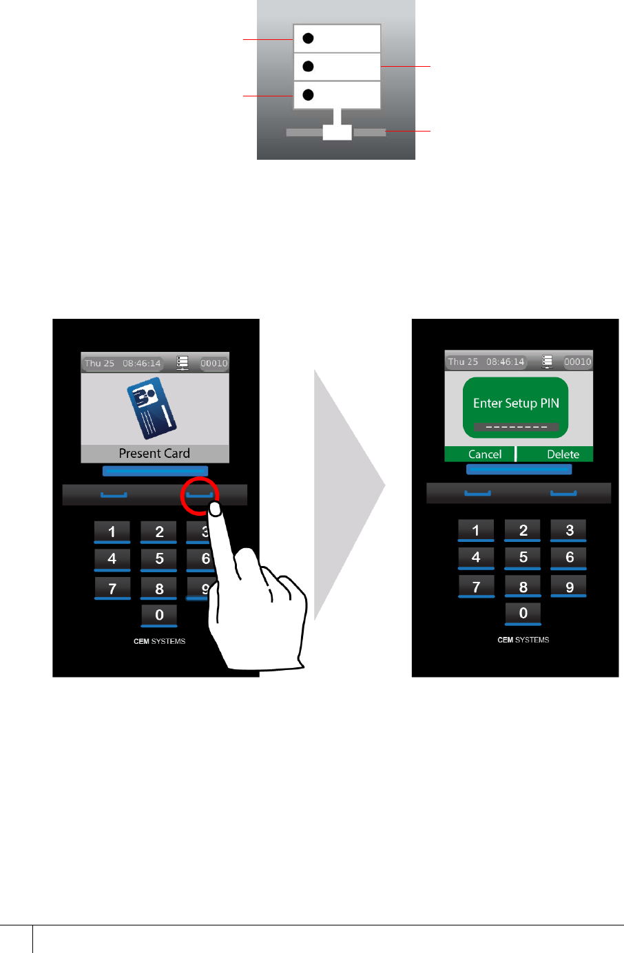
Each section of the status indicator represents a different aspect of the network connectivity.
The presence or absence of a block indicates whether or not the connection is good.
Figure 29 The network status indicator
4.2 Accessing the System Configuration Menu
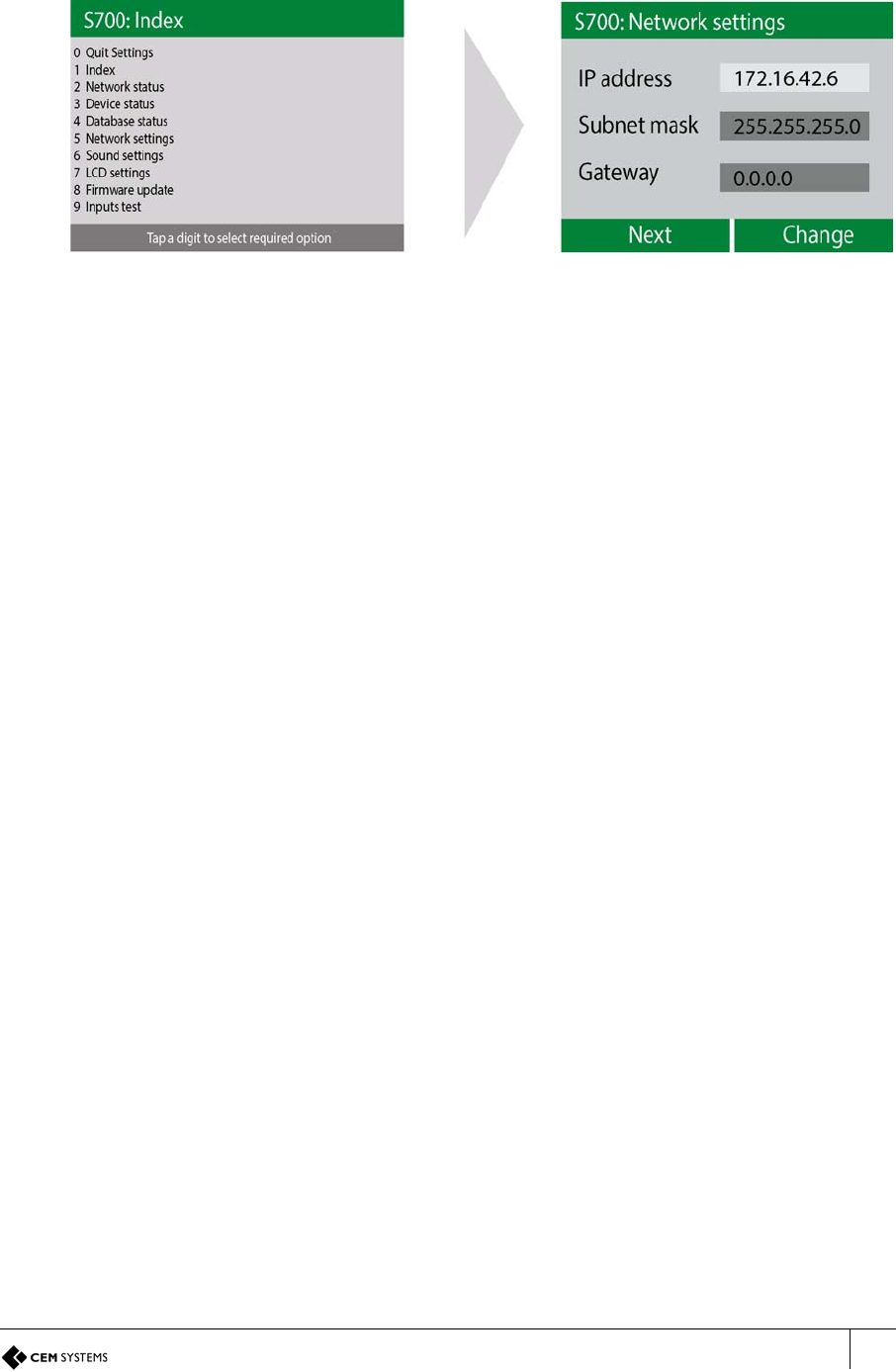
To access the configuration menu, complete the following steps:
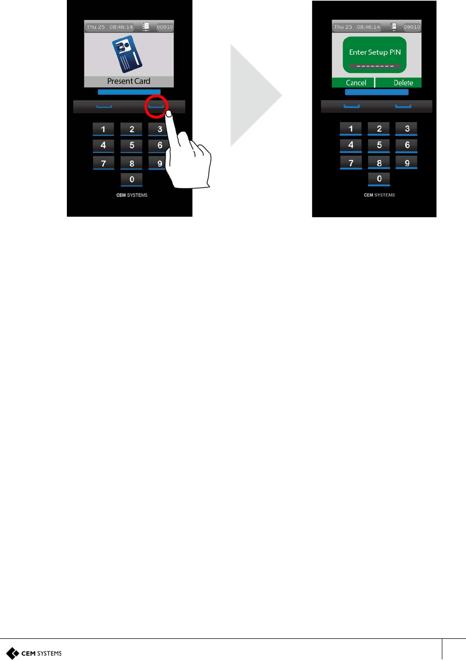
1. On the terminal keypad, quickly tap the right function key at least three times.
2. When you are prompted to Enter Setup PIN, type the default code: 67670000.
Figure 30 Accessing the configuration menu
Note: After the AC2000 system setup is complete, the pass code is 6767XXXX, where XXXX
is the code set by the system. The final four digits of this PIN are configurable for the terminal
in the Devices application; for more information on configuring passcodes, see section
Accessing the system configuration menu on page 67.
The top block indicates that
the terminal has received its
onboard database of
cardholders, timezones and
so on
The centre block indicates
that the terminal has received
its configuration settings from
the CDC
The bottom block indicates
that the terminal is connected
with the RTC The TCP/IP indicator shows
Ethernet connectivity
S700 Installation Manual
53
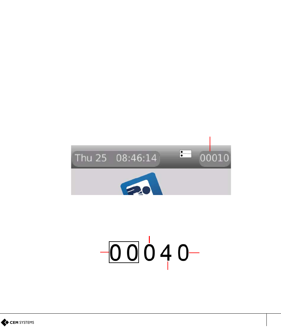
4.2.1 Setting the terminal IP address, gateway, and subnet mask
To set the IP address, gateway, and subnet mask of the terminal, complete the following steps:
1. To access the Network Settings menu, press key 5.
Figure 31 Configuring the terminal network settings
2. Select Next to highlight the relevant field.
3. Select Change to edit the selected field.
4. Enter the IP Address, Subnet mask and Gateway settings using the keypad. Press the
left function for a ‘.’
5. To exit settings, press key 0 and select Save to save the new settings, or Quit to discard
changes.

S700-IM-0088-1.72
54
55
Chapter 5
AC2000 Software Configuration
This section of the manual focuses on the initial addition and configuration of the device and input
alarms. All other advanced configuration options are covered in the relevant function sections. The
S700 terminal is added to the AC2000 system and configured using the Devices application.
Note: This manual assumes access to the necessary AC2000 applications and should be
performed by persons trained in its use.
5.1 Reader addressing
The AC2000 system communicates with all devices on the access control network using the
CEM reader addressing system.
All devices are allocated a five-digit reader address, the address is displayed in the top right of
the terminal display.
Figure 32 Location of the reader address on the screen
Each digit of the reader address signifies a position on the Devices hierarchy.
Figure 33 Illustration describing AC2000 reader addressing
Reader address
RTC number ranges
from 00 - DE
Device group number 0 - F
Device number 0 - F
Master / Exit
0 = Master reader
1 = Exit reader
S700-IM-0088-1.72
CHAPTER 5 : AC2000 Software Configuration
56
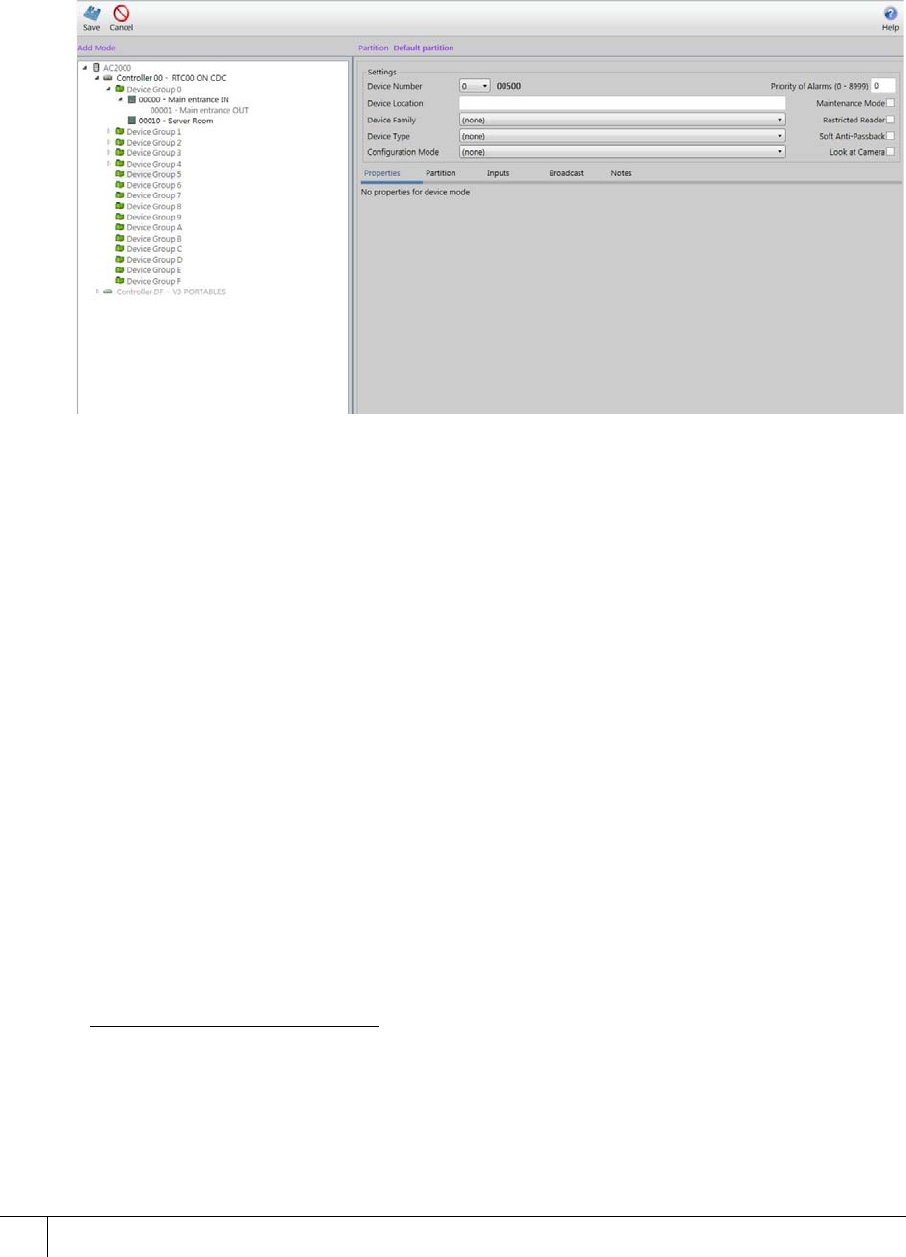
5.2 Adding the device to AC2000
To add the address of a device to AC2000, complete the following steps:
1. Log on to the AC2000 Floatbar, click Device Configuration, and click Devices.
2. Select the controller and device group to which the device is being added.
3. Click Add and select Add Device, or, right-click on the device group and select Add
Device.
The Devices application enters Add Mode. You can add a device.
Figure 34 The Devices application in Add mode
4. Use the drop-down Device Number list to select the device number.
5. Into the Device Location field, enter the device location.
Mixed case is available for the description of the device location.
Note: It is advisable that you use a naming convention for the location of each device,
especially if the AC2000 system is partitioned. This minimises the chance of calling two
devices by the same name, for example, Partition 1: Server Room and Partition 2: Server
Room.
6. Select the Device Family drop-down list to choose the device family. For the S700, select
700E (Ethernet).
7. Select the Device Type drop-down list to choose the device type.1 For the S700, the
device type is S700 + Slave.
8. Select the Configuration Mode drop-down list to choose S700E + Slave.2
9. Select one of the following check boxes if the setting is relevant to your device setup:
– Maintenance Mode
– Restricted Mode
– Soft Anti-Passback
– Look at Camera
1.If an exit or auxiliary device is added to the master reader, ensure to select the correct type, that is,
an S700 device with an Exit Reader has a Device Type of S700 + Slave. This configures the Master
device with an attached exit reader. Any exit reader added to a master appears as a child node in the
Overview Pane of the master reader with which it is associated.
2.The configuration mode contains default settings, however these can be user defined. for more
information on creating a configuration mode, see the Setup Guide for the AC2000 system.
S700 Installation Manual
57
10. If an exit reader has been added by including it in the Device Type, enter a unique Slave
Location to describe the location of the exit reader.
11. Select the Settings tab. Enter the unique MAC Address or IP Address of the device into
the relevant fields.
The unique address of the device is found by navigating from the Configuration Menu to
the Network Status menu on the S700 itself.
12. Select the Offline Database drop-down list and select one of the following two options for
the device:
i. Card Number
ii. Card Number, Timezone, Status, PIN
13. Click Save. This adds the device to the AC2000 system.
Note: Threat groups are only used if threat levels have been activated on AC2000. For further
information, see the AC2000 Threat Levels manual.
5.2.1 Configuring a third-party read head
To configure the Slave to be a third-party read head only, complete the following steps:
Note: Following the instructions, Adding the device to AC2000 on page 56, a Slave is added
to a master reader. The master reader configured the exit reader by default.
1. Log on to the AC2000 Floatbar, click Device Configuration, and click Devices.
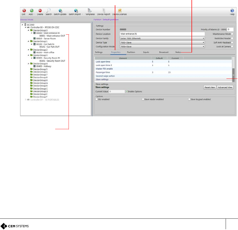
Figure 35 Third-party read head configuration
2. Select the device, with associated exit reader, to be configured.
3. Select the Properties tab.
Properties contains the most commonly used tabs. To access more specialised tabs, click
Advanced View.
4. Select Slave Settings from the list in the Properties pane.
5. In the Slave Settings pane at the bottom of the interface, ensure the Slave reader
enabled check box is clear.
Configuration tabs
Properties tab
Selected
device and
associated
exit reader
Exit
reader
settings
S700-IM-0088-1.72
CHAPTER 5 : AC2000 Software Configuration
58
6. Select Save.
The Exit reader associated with the master device is now configured as a third-party read head
and not an Exit reader.
5.3 Configuring devices
Use the Devices application to configure the inputs that are used to trigger alarms or events in
the AC2000 system.
5.3.1 Adding an input alarm
To add an input alarm to a device, complete the following steps:
1. Log on to the AC2000 Floatbar, click Device Configuration, and click Devices.
2. Select the device to configure from the overview pane on the left of the screen.
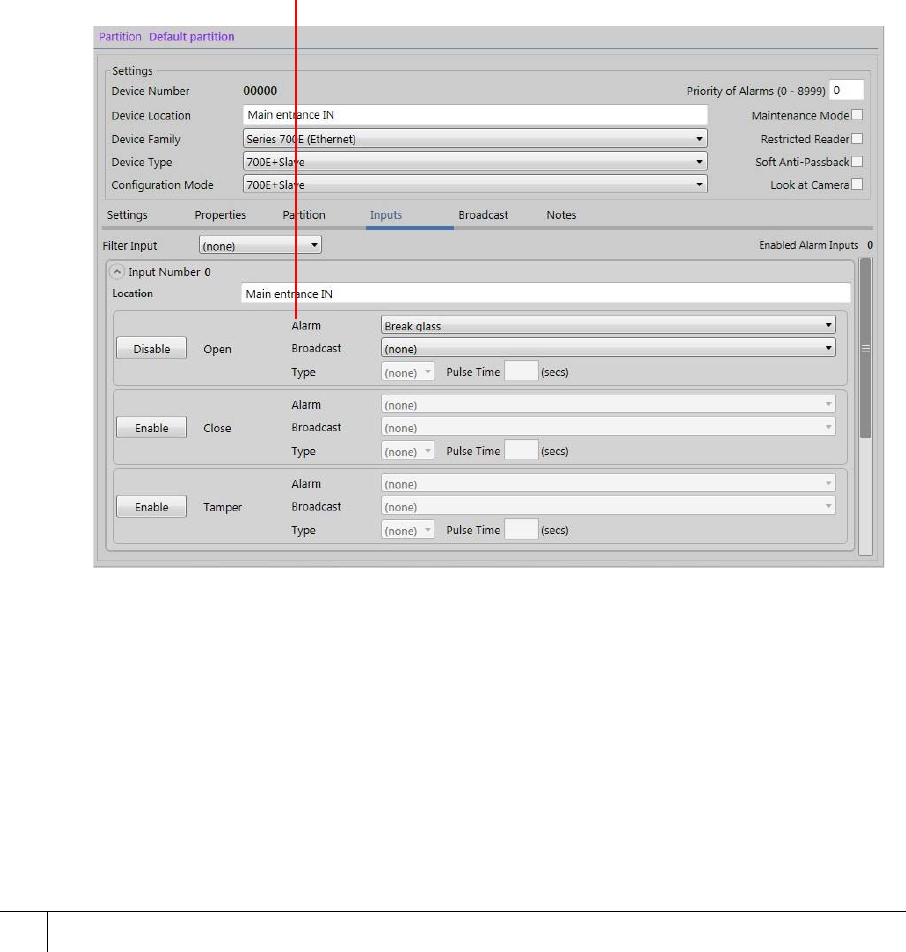
3. Select the Inputs tab on the main pane.
4. Click Enable and the Alarm and Broadcast drop-down lists became active.
Figure 36 Adding inputs dialog with example input 0 configuration
5. From the Alarm drop-down list, select an alarm type.
6. From the Broadcast drop-down list, select a broadcast type.
7. Select the alarm Type from the drop-down list.
8. In the Pulse Time box, set the time in seconds.
9. Click Save.
Alarm
type
S700 Installation Manual
59
5.3.2 Configuring 4-state tamper inputs
To configure the 4-state tamper inputs, complete the following steps:
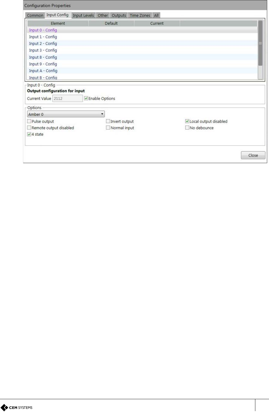
Figure 37 4-state tamper
1. Log on to the AC2000 Floatbar, click Device Configuration, and click Devices.
2. Select the device to configure from the overview pane on the left of the screen.
3. Select the Properties tab, and click Advanced View.
4. Select the Input Config tab.
5. Select each input element to be configured and select the 4 state check box.
6. Click Save.
Note: The following instructions are only required if the settings need to be edited during or
after terminal installation.
5.3.3 Editing device properties
To edit the device properties, complete the following steps:
1. Select the master device in the overview pane.
2. Make the required changes and click Save.
5.3.4 Editing a device input
To edit a device input, complete the following steps:
1. Select the Input and the Input State that is to be edited from the Device Inputs list.
2. Click Save when changes have been completed.
Note: Save is only displayed when a change has been made.
S700-IM-0088-1.72
CHAPTER 5 : AC2000 Software Configuration
60
5.3.5 Deleting a device input
To delete a device input, complete the following steps:
1. Select the input from the Device Inputs list.
2. Click Delete.
3. From the window that appears, click Delete to delete the device from the system or
Cancel to cancel the process.
Note: Care should be taken when deleting an input as no warning message appears.
5.3.6 Input alarms
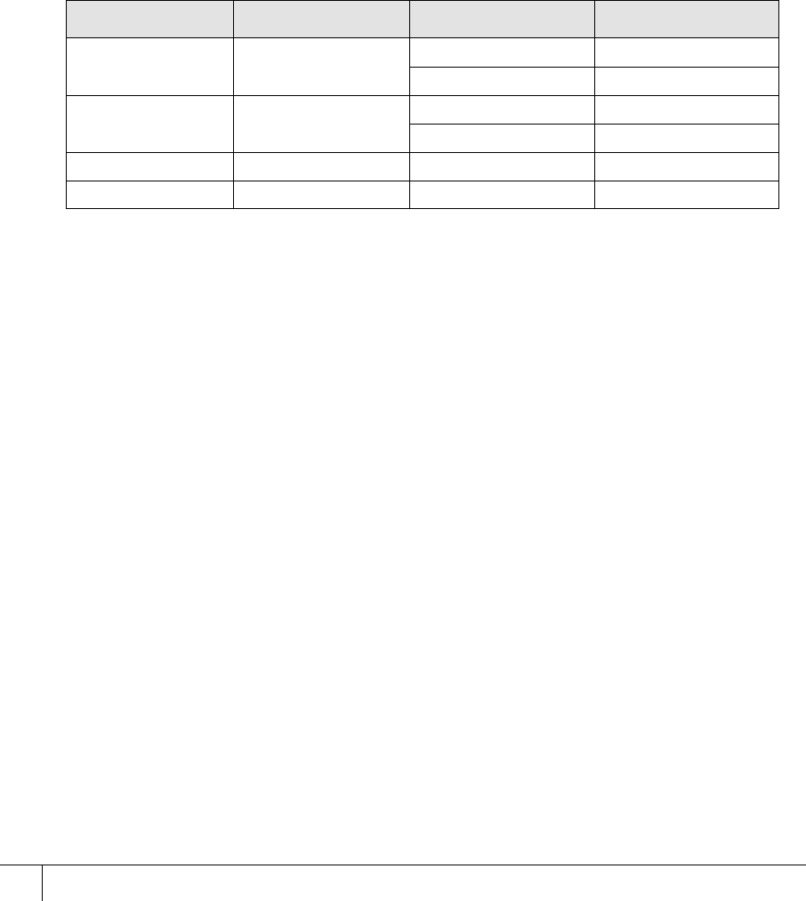
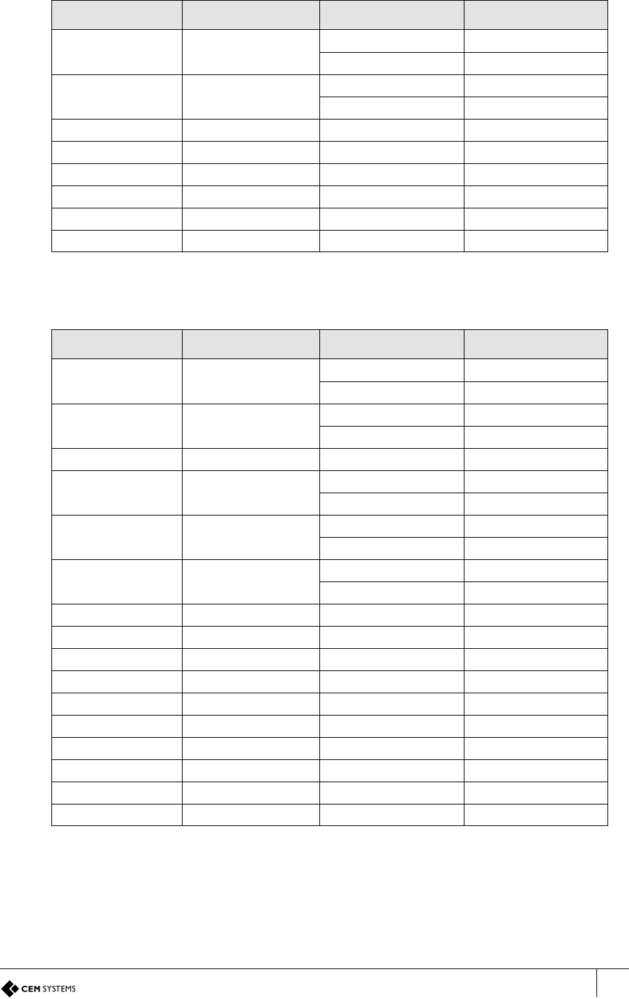
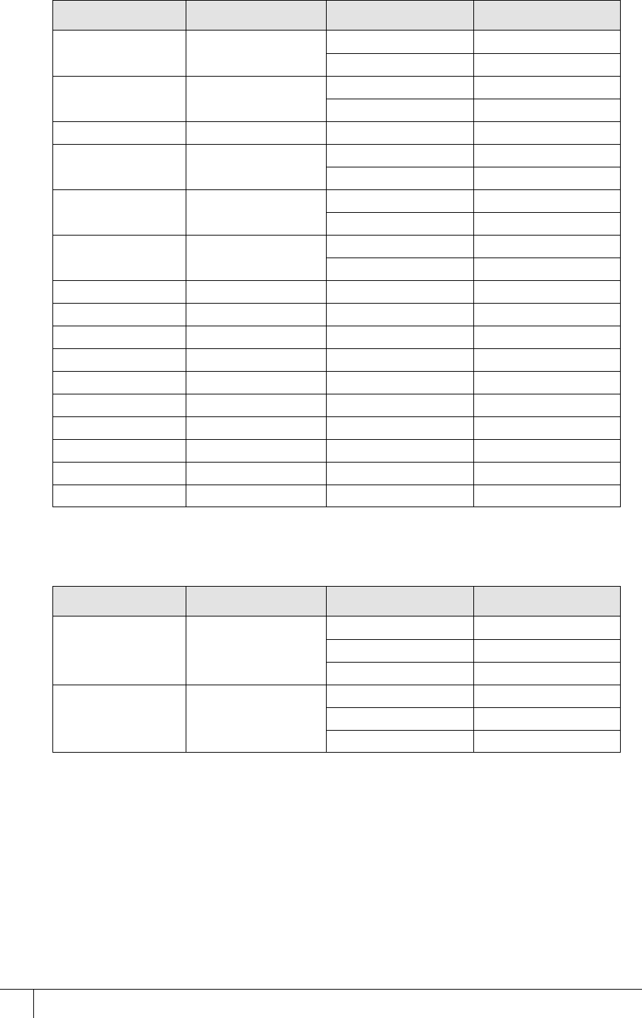
The following input tables describe the set-up for each of the S700 configurations outlined in
this manual, including the AC2000 alarms that must be selected for each sensor state where
appropriate:
Input table for S700 with REX and S700 with third-party read head:
Input number Input function Sensor state AED alarm
0 Door position Open Door forced
Closed Door closed
1 Lock position Open Lock not engaged
Closed Lock engaged
2 Request to exit No default
3 Spare / interlock No default
Table 22: S700 and REX / Third-party read head input alarms
S700 Installation Manual
61
Input table for S700 with S700s exit reader
Input table for S700 with DIU210 and S710s exit reader:
Input number Input function Sensor state AED alarm
0 Door position Open Door forced
Closed Door closed
1 Lock position Open Lock not engaged
Closed Lock engaged
2 Request to exit No default
3 Spare / interlock No default
4 Spare No default
5 Spare No default
6 Spare No default
7 Spare No default
Table 23: S700 and S700s exit reader input alarms
Input number Input function Sensor state AED alarm
0 Door position Open Door forced
Closed Door closed
1 Lock position Open Lock not engaged
Closed Lock engaged
2 Request to exit No default
3 Break glass Open Breakglass
Closed Breakglass reset
4 Fire Open Fire alarm
Closed Fire alarm reset
5 Mains power fail Open Mains power fail
Closed Mains OK
6 Battery low Open DIU battery low
7 DIU tamper switch Open DIU tamper
8 Spare No default
9 Spare No default
A Spare No default
B Spare / interlock No default
C Spare No default
D Spare No default
E Spare No default
F Spare No default
Table 24: S700 and DIU210 input alarms
S700-IM-0088-1.72
CHAPTER 5 : AC2000 Software Configuration
62
Input table for S700 with DIU230 and S700s exit reader
Input table for four-state tamper configuration
5.4 Next steps
The S700 terminal is fully installed. The remainder of the manual details how to perform more
complex tasks with the terminal including:
• Using the system configuration menu to view maintenance information and perform
terminal tests
• Configuring the terminal in additional modes such as Passenger Mode and Door Control.
Input number Input function Sensor state AED alarm
0 Door position Open Door forced
Closed Door closed
1 Lock position Open Lock not engaged
Closed Lock engaged
2 Request to exit No default
3 Fire Open Fire alarm
Closed Fire alarm reset
4 Break glass Open Break glass
Closed Break glass reset
5 Mains power fail Open Mains power fail
Closed Mains OK
6 Battery low Open DIU battery low
7 DIU tamper switch Open DIU tamper
8 Spare No default
9 Spare No default
A Spare No default
B Spare / interlock No default
C Spare No default
D Spare No default
E Spare No default
F Spare No default
Table 25: S700e with DIU230 and S700s input alarms
Input number Input function Sensor state AED alarm
0 Door position Open Door forced
Closed Door closed
Tamper Input Tamper
1 Lock position Open Lock not engaged
Closed Lock engaged
Tamper Input Tamper
Table 26: Input table for four-state tamper configuration

S700 Installation Manual
63
• Upgrading terminal firmware
• Configuring device settings using the Device Settings Remote Application
Important: Advanced configuration of the terminal must only be carried out by users that have
completed CEM AC2000 installer training.

S700-IM-0088-1.72
64

65
Chapter 6
The System Configuration Menu
The S700 utilises a Graphical User Interface (GUI) to access terminal functionality. At the basic level,
the screen is used to display messages regarding the current card swipe transaction. The more
advanced options allow the user to access information and reports that are relevant to them.
The S700 screen is a high quality, full colour, LCD screen. This is complimented by a capacitive touch
keypad, which is highly responsive in multiple weather conditions. The reader interface provides
access to a variety of tools, reports and information, such the as the following:
• Terminal configuration options
• Diagnostics and tests
• Software and hardware versions
S700-IM-0088-1.72
CHAPTER 6 : The System Configuration Menu
66
6.1 Menu overview
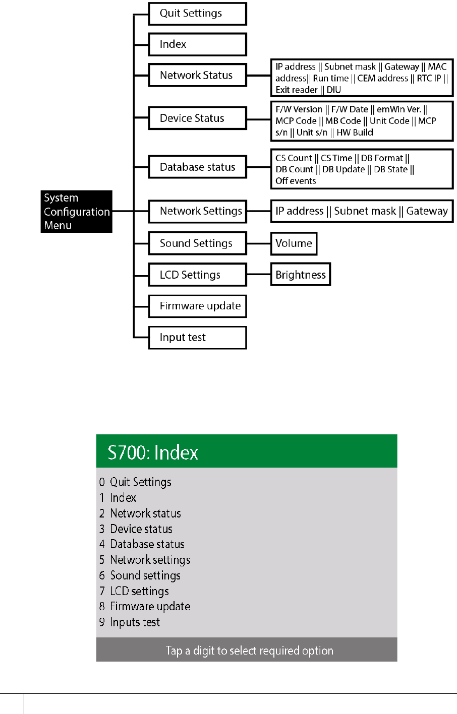
The following image is an overview of the System Configuration Menu.
Figure 38 Overview of the System Configuration Menu
6.2 Navigation
You can access the menus on the terminal by touching the number on the keypad that
corresponds to the menu designation.
Figure 39 Expanding and closing reader menus
S700 Installation Manual
67
6.3 Accessing the system configuration menu
To access the configuration menu, complete the following steps:
1. On the keypad terminal, quickly tap the right function key at least three times.
2. When prompted to enter a passcode, type 6767000.
Note: See Accessing the System Configuration Menu on page 52 for more details on
passcodes.
Figure 40 Accessing the configuration menu
Configuring the passcode
To configure the passcode, complete the following steps:
Note: You can change the final four digits of the passcode, making it specific to a site or
reader.
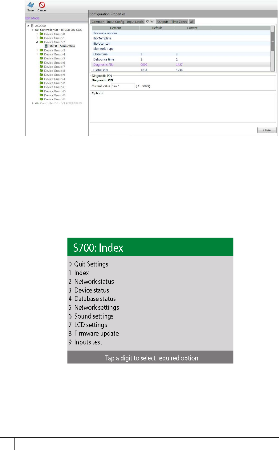
1. Access the AC2000 system through the AC2000 workstation interface. enter your
username and password.
2. Log on to the AC2000 Floatbar and open the Devices application.
3. In Devices, select the relevant reader.
4. Select the Properties tab and click Advanced View.
5. Select Other and click Diagnostic PIN from the options.
Note: You must scroll down to locate the Diagnostic PIN option.
S700-IM-0088-1.72
CHAPTER 6 : The System Configuration Menu
68
Figure 41 Diagnostic PIN
6. Into the Current Value field, type your new PIN and click Close.
7. To save the new PIN, click Save.
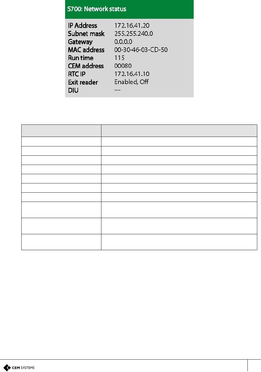
The System Configuration Menu has a 10-option list, each of which contains specific terminal
maintenance functions.
6.3.1 Device settings menu
Important: You must have the following information before contacting CEM Support with any
issues.
Figure 42 The system configuration menu
You can access the following settings through the System Configuration Menu. The following
settings are available:
Quit Settings: key 0
Use this setting to exit the System Configuration Menu and return to the terminal home screen.
S700 Installation Manual
69
Index: key 1
Use the index to return to the System Configuration Menu from any point in the menu system.
Network status: key 2
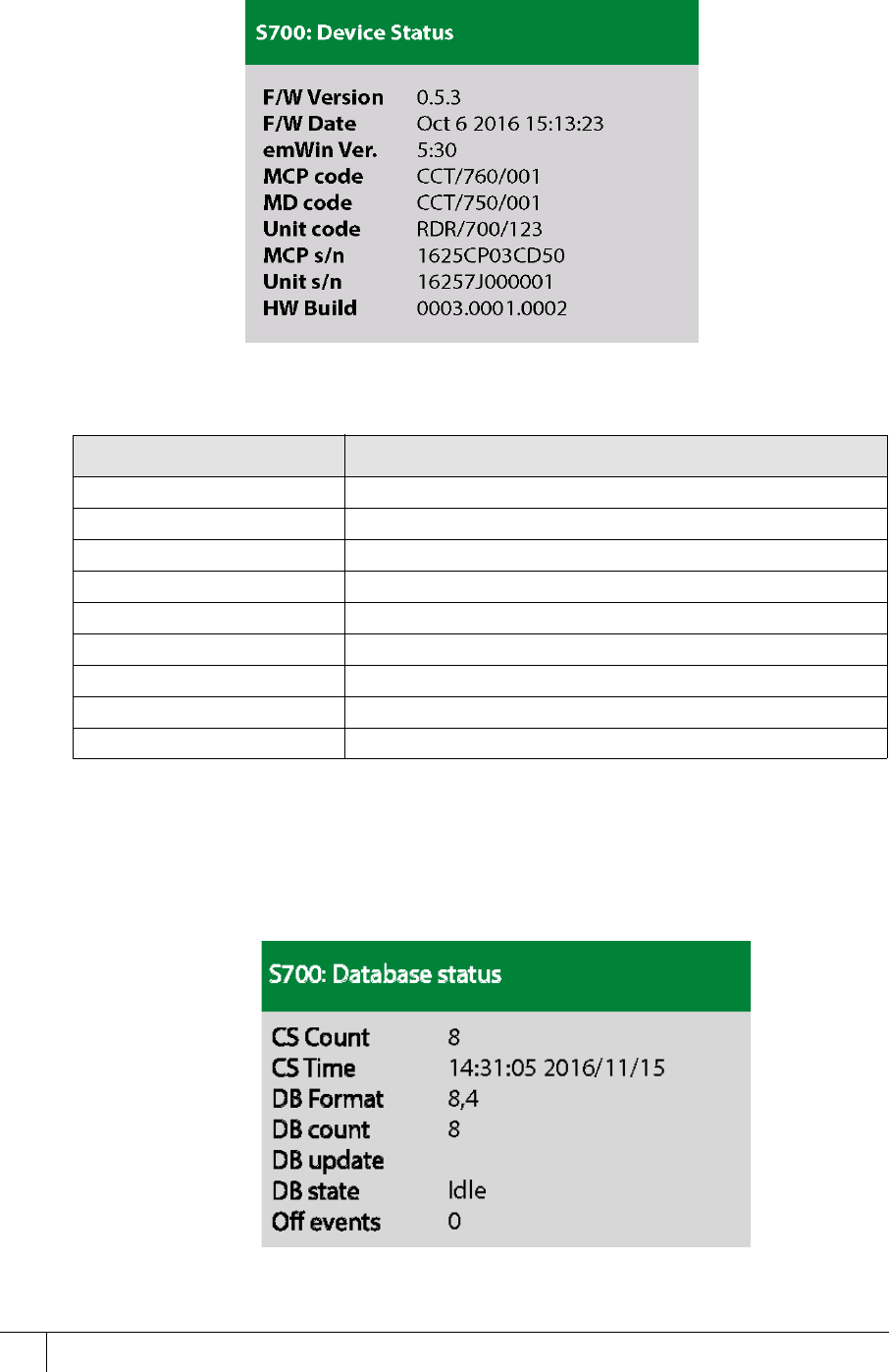
Use the Network status information section to view details about terminal network settings.
Figure 43 Network status
Table 27: Network status describes the fields in the Network status information window:
Information Description
IP address The IP address of the terminal
Subnet mask The subnet mask of the network hosting the terminal
Gateway The IP address of the gateway server
MAC address The MAC address of the terminal
Run time Total terminal run time since the system was last reset
CEM address The CEM reader address of the terminal
RTC IP The IP address of the RTC controlled the terminal
Exit reader Indicates if an exit reader has been enabled in AC2000
and if it is operating
DIU Indicates if a Door Interface Unit has been enabled in
AC2000 and if it is operating
OSDP head Indicates if an OSDP third-party head has been enabled in
the AC2000 system, and, if it is operating
Table 27: Network status
S700-IM-0088-1.72
CHAPTER 6 : The System Configuration Menu
70
Device Status: key 3
Use the Device status information section to view details about all the hardware and software
versions of the terminal.
Figure 44 Device status
Table 28: Device settings describes the fields in the Device status information window:
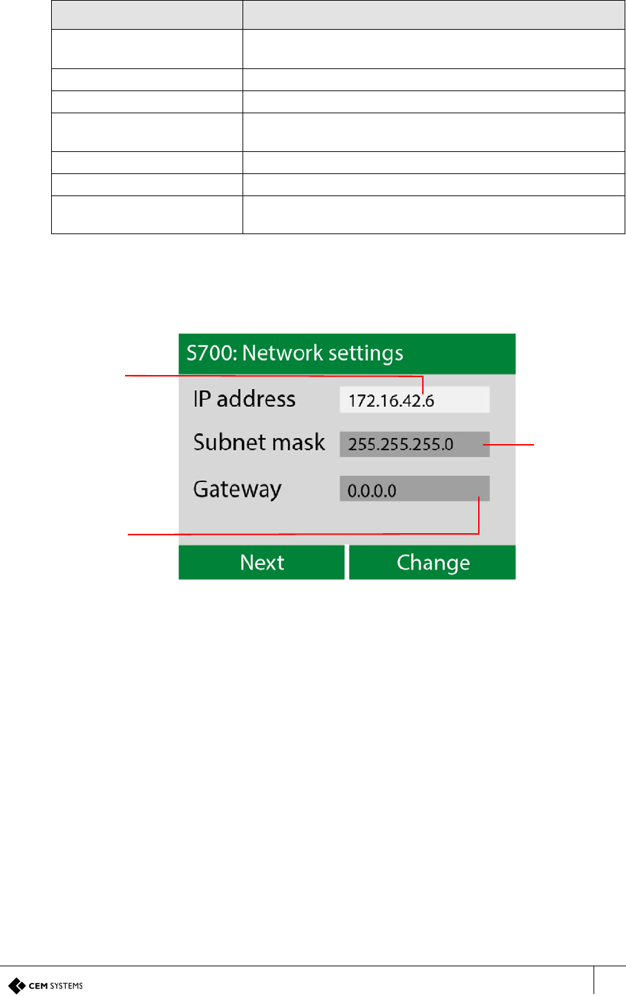
Database Status: key 4
Use the Database status information section to view detailed information about the onboard
card database.
Figure 45 Database status
Information Description
F/W Version Firmware version
F/W Date Date of firmware build
emWin Ver. Graphics library version
MCP Code Micro card processor part number
MD Code Main board part number
Unit Code Terminal part number
MCP s/n Micro card processor serial number
Unit s/n Terminal serial number
HW Build Terminal hardware build
Table 28: Device settings
S700 Installation Manual
71
Table 29: Database status describes the fields in the Database status information window:
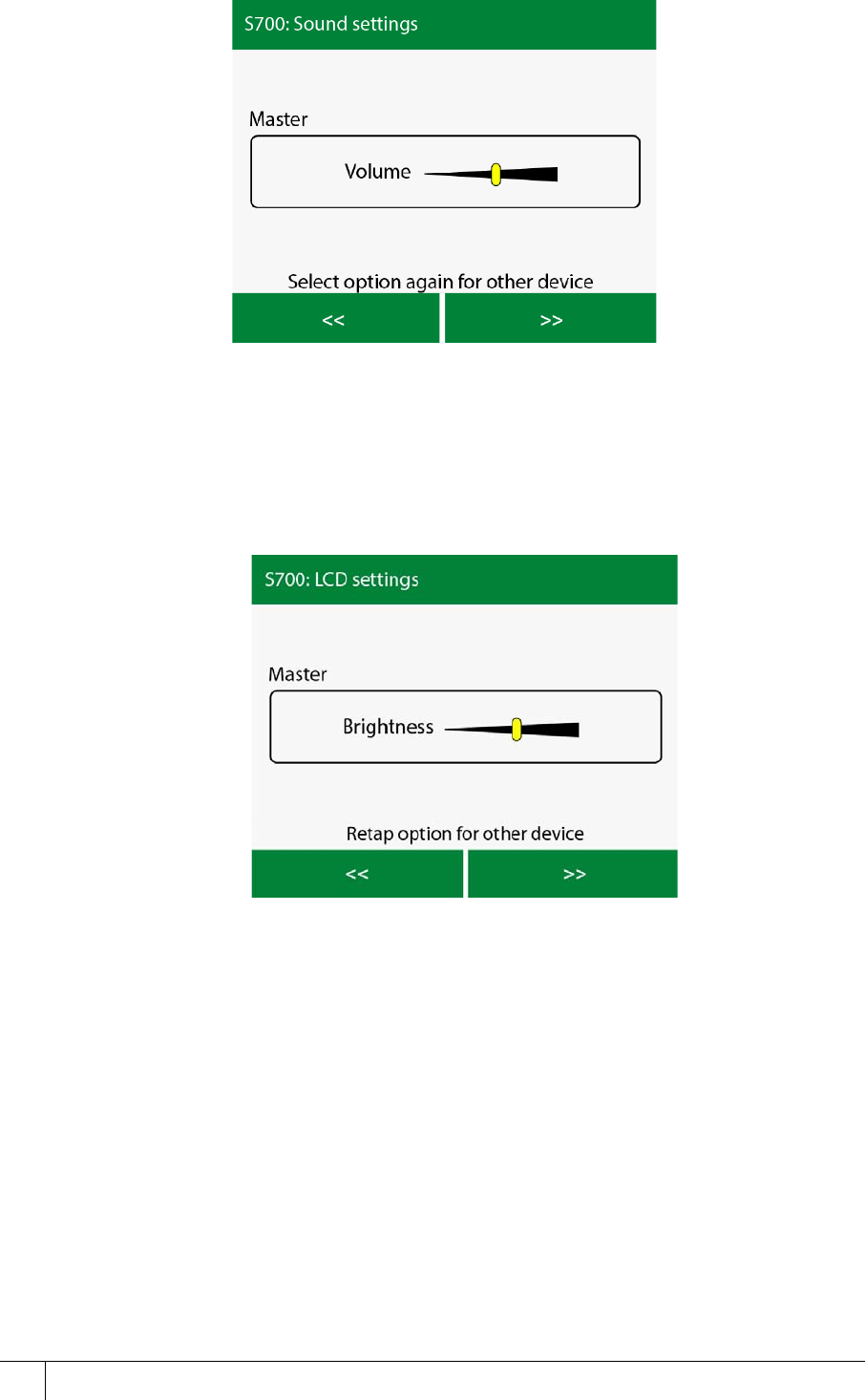
Network Settings: key 5
The Network Settings section contains information the installer uses to configure the terminal
network settings.
Figure 46 Network Settings
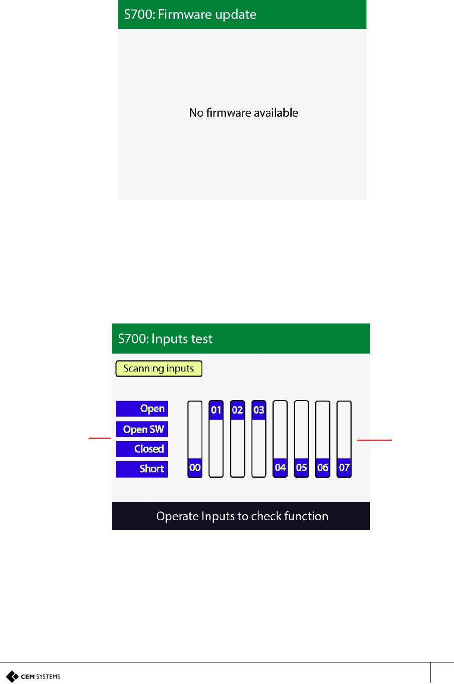
Sound Settings: key 6
Use the Sound settings menu to change the volume of the internal speaker on the terminal.
Information Description
CS Count The number of card records with which the local database
was initialized
CS Time This is the time the local card database was last initialised
DB Format This shows the database format
DB Count This is the current number of valid cards in the local
database
DB update This shows the time of the last database update
DB state This shows the database state
Off events This is the number of offline buffered event waiting to be
uploaded to the server
Table 29: Database status
Subnet mask
displays the
address of
the network
to which the
terminal is
connected
Gateway
displays the
IP address of
the gateway
server -
where it is
appropriate
IP address
displays the
IP address
assigned to
the terminal
S700-IM-0088-1.72
CHAPTER 6 : The System Configuration Menu
72
Figure 47 Sound Settings
Selecting this menu option twice can be used to change the setting on the exit reader.
LCD Brightness: key 7
Use the LCD Brightness menu to change the brightness of the terminal LCD screen to be
adjusted.
Selecting this menu option twice can be used to change the setting on the exit reader.
Figure 48 LCD Brightness
S700 Installation Manual
73
Firmware Update: key 8
The Firmware Update menu can be used to update the firmware if updates are available.
A complete description of the firmware update process can be found in Updating Firmware on
page 91.
Figure 49 Firmware Update
Inputs Tests: key 9
The S700 terminal has built-in tests that can be performed to check specific functionality.
The Input tests screen displays the four terminal inputs states. When peripherals such as the
exit reader or the Door Interface Unit are attached to the terminal, their inputs are also
displayed on the screen.
Figure 50 Inputs test
The Inputs test screen displays the following input states and inputs:
• Input state: To test the inputs, change the state of the input, for example, open and close
the door to test if the terminal is registered the state change.
• Inputs: Each number correlates with a terminal input number as detailed in Wiring the
Terminal on page 29. For example, input 0 is door position. The position of each input
corresponds to an input state, which is defined on the left of the screen.
Input state Inputs

S700-IM-0088-1.72
CHAPTER 6 : The System Configuration Menu
74
Two-state input test
When an input is wired in a 2-state open and closed configuration, only the Open and Short
tests can be administered.
These states are as follows:
Open: The input is open
Short: The input is closed
Four-state input test
When an input has been wired in a 4-state configuration, all four input state tests can be
administered. For more information on configuration, see Configuration information on
page 36.
The following states are outlined as follows:
Open: Indicates a tamper cut condition
Open SW: The input is open
Closed: The input is closed
Short: Indicates a tamper short condition

75
Chapter 7
S700 Operational Modes
The S700 intelligent access terminal can be configured to function in different modes other
than the standard door mode described in the main section of the manual. The Door mode list
in Devices is as follows:
• Door
• Turnstile
• Turnstile (Pulse)
• Passenger
• Equipment
7.1 Door mode timings
Door mode is the normal terminal configuration that is described in the main installation
section of this manual. Use door mode to allow a terminal to control access to a door and
monitor specific inputs associated with that door.
When a valid card is presented at a terminal in door mode, a chain of events takes place. This
chain is dictated by specific settings in the Devices application. These timings are configurable
in the Devices application and also on the terminal itself.
The chain of events is outlined in the following section, S700: Door mode timing on page 75.
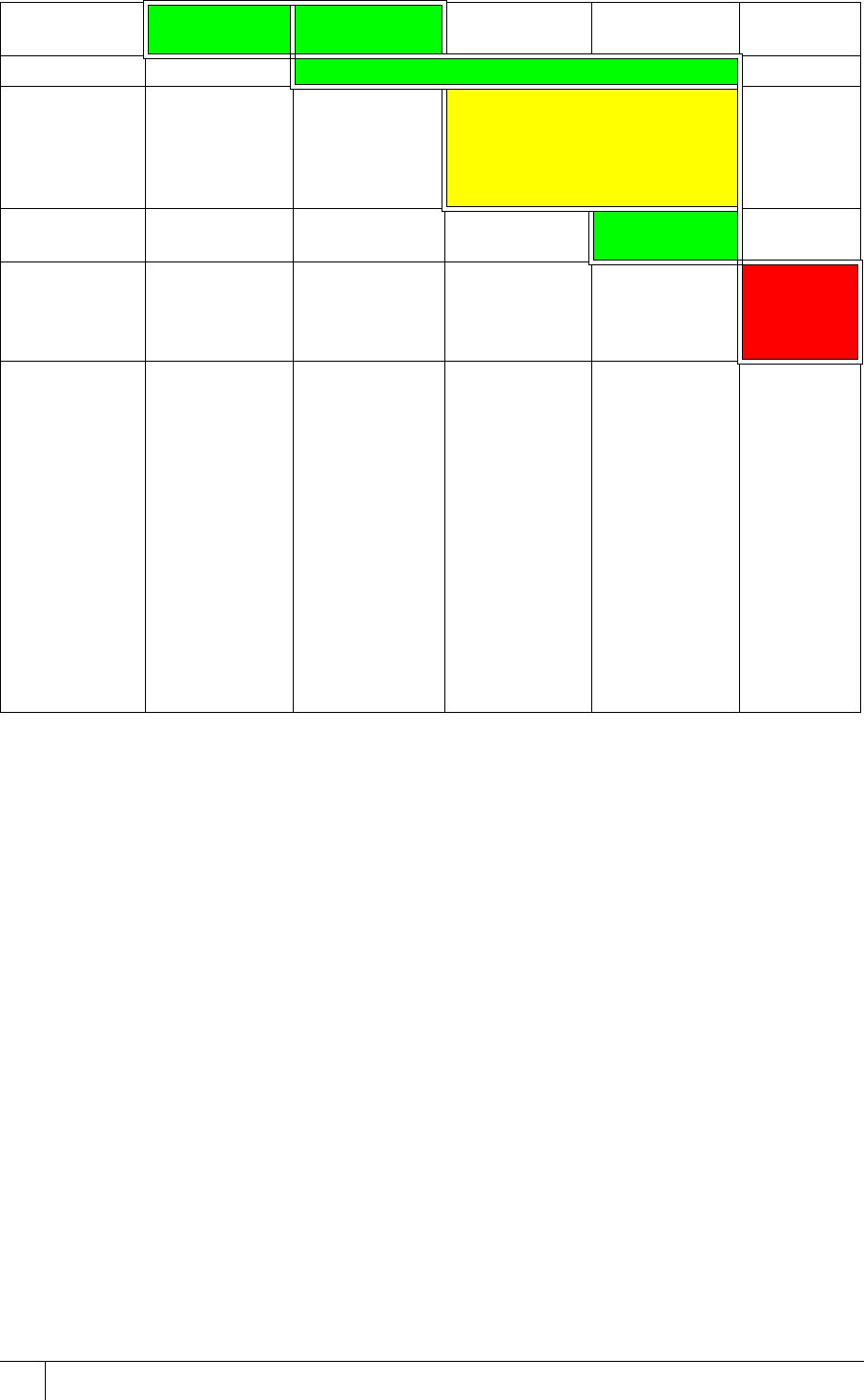
S700: Door mode timing
The following chart shows the timing sequence for a typical door mode.
The door event starts on the left and move right as events and time occur.
A valid card, remote Oneshot or REX (Request to Exit) input, typically starts the Lock Open
Time sequence.
S700-IM-0088-1.72
CHAPTER 7 : S700 Operational Modes
76
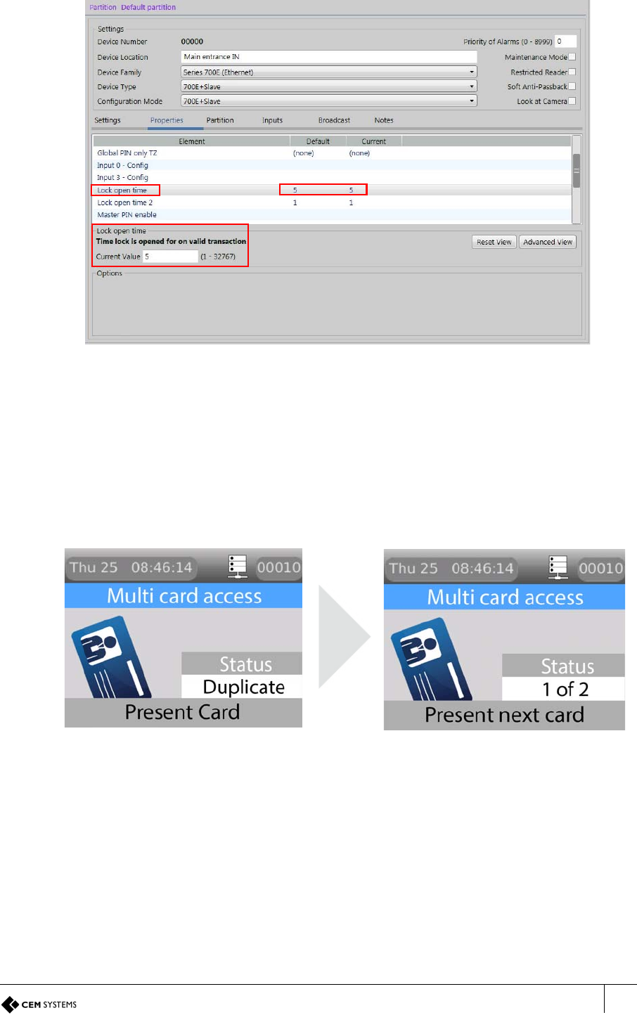
Table 30: Illustration of door timings
The following steps outline the door open cycle:
1. The valid card is swiped at the terminal and access is granted.
2. Lock power is dropped for a period of time known as Lock open time: five second default.
If the door is not opened by the end of this time, the lock re-engages.
3. After the door is opened by the cardholder the lock power remains off for a period of time
to prevent the lock re-engaging and closing the door before it is fully opened. This is the
Lock open time 2. The default for this is one second.
4. The door is closed. If the door remains open longer than the Door close after time, a door
held alarm is generated on the terminal and the AC2000 system. The default is 15
seconds.
Configuring the timings in the Devices application
To configure timings in the Devices application, complete the followings steps:
1. Log on to the AC2000 Floatbar, click Device Configuration, and click Devices.
2. Select the terminal you want to modify and select the Properties tab.
Lock output Lock Open
Time Lock Open Time
Normal open Door close after
Sounder
warning,
legal open
time
running out
Pre-alarm
Allowing time
to close Close time
Door held
alarm and
alarm
sounder
Alarm Time
Notes If the door is not
detected
open before
the Lock
Open Time
period
expires, the
lock is re-
secured and
the door
mode returns
to the idle
state
The door has
been
detected
open
If the door is
detected
closed before
the Door
close after
period, the
Lock Open
Time 2 is
cancelled
and the door
mode returns
to the idle
state
The pre-alarm
starts the
defined
second
before Door
close after
expires
Close Time
is to allow
an
automatic
door time
to close
when the
cycle is
complete;
the pre-
alarm
continues
during the
Close
Time
S700 Installation Manual
77
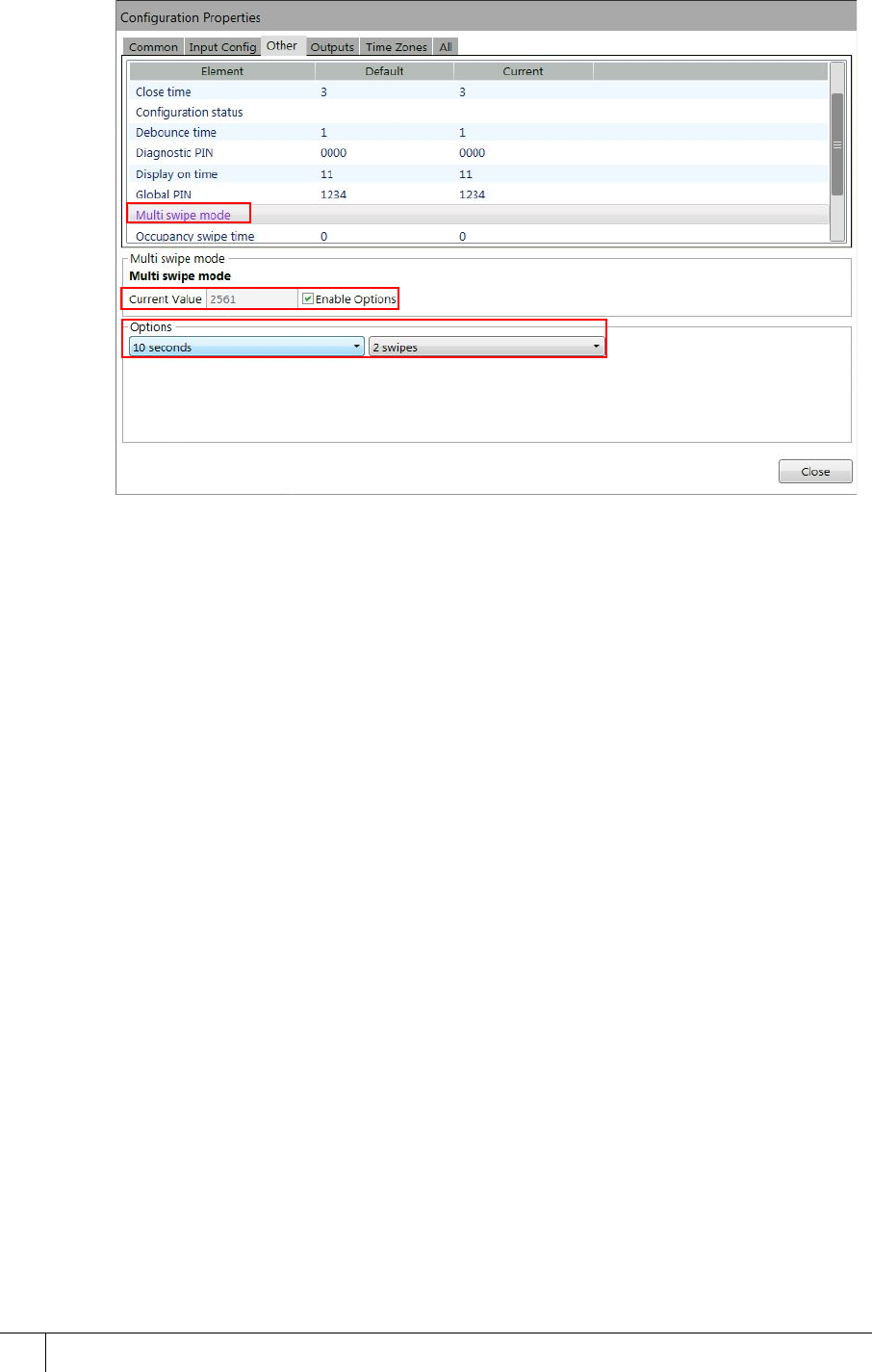
3. From the main panel, select the timing you want to amend. This panel is shown in the
following figure. Update the value you require in seconds.
Figure 51 Updating the door cycle timings
Door mode is the default terminal configuration that is described in the main installation section
of this manual. Use door mode to allow a terminal to control access to a door and monitor
specific inputs associated with that door.
7.1.1 Multi-swipe access
The S700 terminal can be configured to require swipes from up to five valid cards before
granting access. Configure this using the Devices application. When this setting is configured,
an initial valid swipe prompts a request for further valid swipes on the screen before opening
the door. When all valid cards are swiped the terminal grants the user access.
Figure 52 Multi-swipe request screen and access granted screen
The multi-card request swipe screen shows the number of valid cards required to grant
access, up to a maximum of five cards. As each valid card is swiped, the S700 reader
increments the card values shown in the card count display section and access is granted.
Software configuration for multi-swipe access
To activate multi-swipe access mode, complete the following steps:
1. Log on to the AC2000 Floatbar, click Device Configuration, and click Devices.
2. Select the terminal you want to configure.
3. Select the Properties tab and click Advanced View.
S700-IM-0088-1.72
CHAPTER 7 : S700 Operational Modes
78
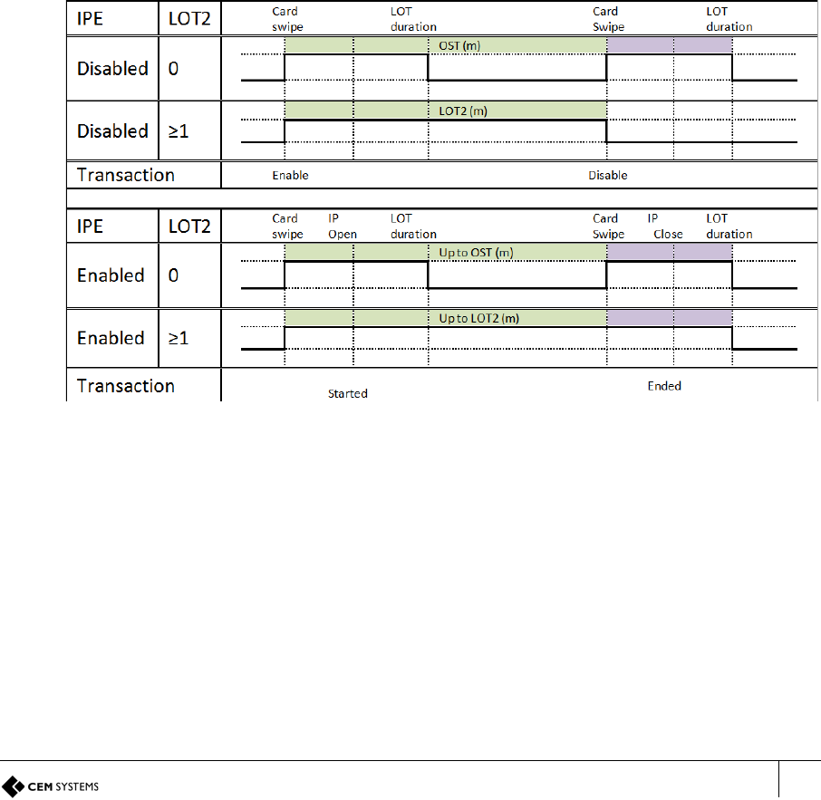
4. Select Other, and select Multi swipe mode.
5. Select the Enable Options check box.
Figure 53 Configuring multi-swipe access
6. Use the drop-down Options lists to configure Multi swipe mode. In Figure 53 Configuring
multi-swipe access the options are configured to 10 seconds and 2 swipes.
S700 Installation Manual
79
7.2 Passenger Mode
Passenger mode enables a door to stay open for a longer period of time when swiped with a
special usage card. This configuration is frequently used in airports to allow the free access of
passengers through the door.
When the reader is in this mode, it allows a normal card access through the door. However, a
card that has been assigned Special Usage in the Personnel application is given the option to
open the door as Staff or Passenger.
Passenger mode keeps the door open for an extended period of time. The default time is 30
minutes.
7.2.1 Configuring passenger mode in the software
For passenger mode to work correctly, the terminal must be configured in passenger mode
and the cardholders using that terminal must be allocated special usage in the Personnel
application. To activate special usage, select the Special Usage check box in the personnel
record of the relevant cardholder.
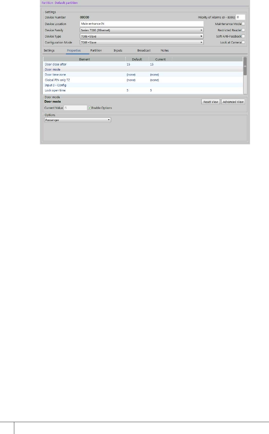
Card Swipe to End Mode
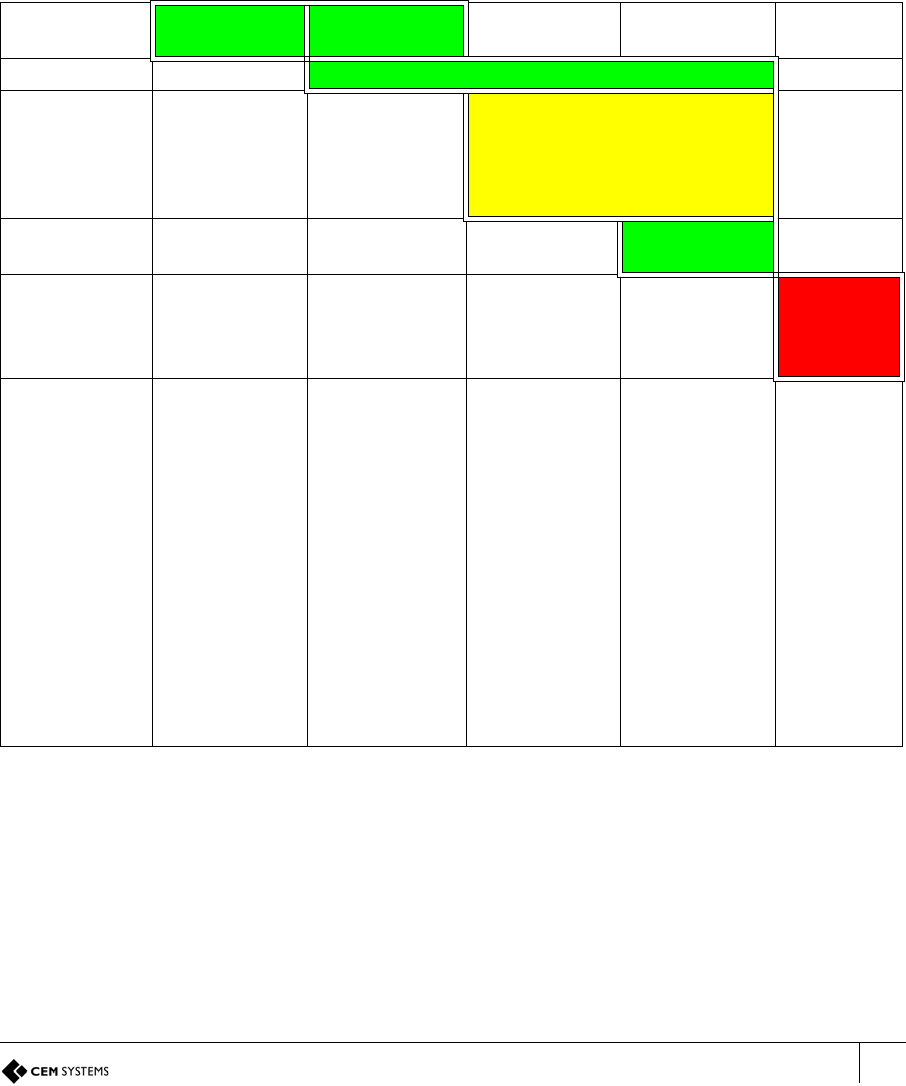
Figure 54 Timing diagrams shows the timing sequences that take place when a card swipe is
used to start and end the activation of third-party equipment. It also shows the options of either
using or not using activations sensing.
Figure 54 Timing diagrams
Configuring the terminal as a passenger mode terminal
To configure the terminal as a passenger mode terminal, complete the following steps:
1. Log on to the Floatbar, click Device Configuration, and click Devices.
2. Select the terminal from the list and select the Properties tab.
S700-IM-0088-1.72
CHAPTER 7 : S700 Operational Modes
80
3. Select the terminal you want to configure.
Figure 55 Configuring passenger mode
4. Select Door Mode. You may have to scroll down to see this option.
5. Use the Options drop-down list to select Passenger.
6. Ensure the Enable Options check box is selected.
7. Click Save on the toolbar of the Devices application.
S700 Installation Manual
81
Adding special access to a cardholder
To add special access to a cardholder, complete the following steps:
1. Log on to the AC2000 Floatbar, click Enrolment, and click Personnel.
2. Search for the cardholder to which the special access is to be applied.
3. Select the Special Usage check box.
4. Click Save.
7.2.2 The passenger mode cycle
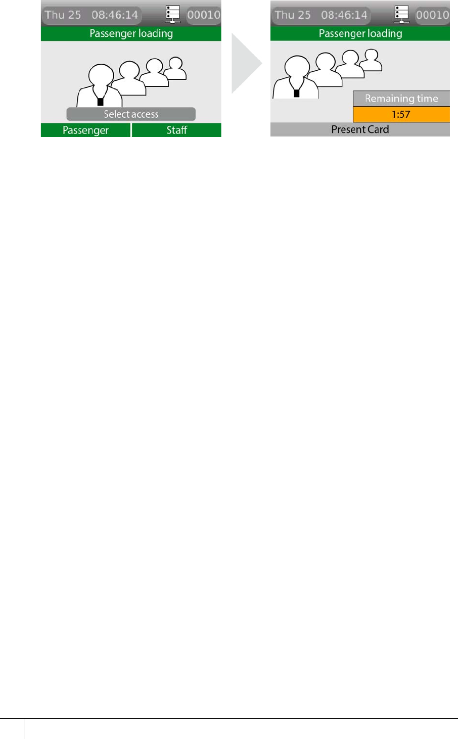
Table 31: Illustration of passenger mode timing outlines the door open cycle. The passenger
mode cycle is located within that cycle; it is only available to the system if Passenger mode is
selected.
Table 31: Illustration of passenger mode timing
To activate passenger mode on a terminal, complete the following steps:
1. To give a cardholder the ability to use the door in Passenger mode, you must go to their
Personnel record on the AC2000 system. When you locate their record using the
Personnel application, select the Special Usage check box. When the check box is
selected, Passenger mode is activated for those cardholders who swipe their access cards
on this terminal.
2. The terminal asks the cardholder if they require Passenger or Staff. Click the left function
key for Passenger and the right function key for Staff. Selecting staff access causes the
terminal to act as in Door Mode.
Lock output Lock Open
Time Lock Open Time
Normal open Door close after
Sounder
warning,
legal open
time
running out
Pre-alarm
Allowing time
to close Close time
Door held
alarm and
alarm
sounder
Alarm Time
Notes If the door is not
detected
open before
the Lock
Open Time
period
expires, the
lock is re-
secured and
the door
mode returns
to the idle
state
The door has
been
detected
open
If the door is
detected
closed before
the Door
close after
period, the
Lock Open
Time 2 is
cancelled
and the door
mode returns
to the idle
state
The pre-alarm
starts the
defined
second
before Door
close after
expires
Close Time
is to allow
an
automatic
door time
to close
when the
cycle is
complete;
the pre-
alarm
continues
during the
Close
Time
S700-IM-0088-1.72
CHAPTER 7 : S700 Operational Modes
82
3. The cardholder selects Passenger.
Figure 56 Pressing the passenger operations button
4. Lock power is dropped for a period of time known as Lock open time - this has a five
second default time. If the door is not opened by the end of this time, the lock re-engages.
5. After the door is opened, the lock power remains off for a period of time to prevent the lock
re-engaging and closing the door before it is fully opened. This is the Lock open time 2.
The default time for this is one second.
6. After the previous two steps, the terminal enters Passenger Mode and the door can be
held open for the period of time before an alarm sounds. The default time for this is three
minutes. The period of time is defined using the Passenger time option in the Devices
application.
7. You can deactivate Passenger mode by swiping a valid Special Usage card and selecting
Finish.
7.2.3 Lobby mode
Lobby mode is a combination of passenger mode and interlocking terminals. Two terminals
may be interlocked directly, or more than two terminals may be interlocked using a third-party
logic controller or interposing relays.
In lobby mode, as long as one door is open in passenger mode, interlocked doors are locked
out to passengers but can be accessed with a valid card swipe from a special-usage
cardholder.
7.3 Interlock
Interlocking terminals are linked together so that only one terminal opens its door at any given
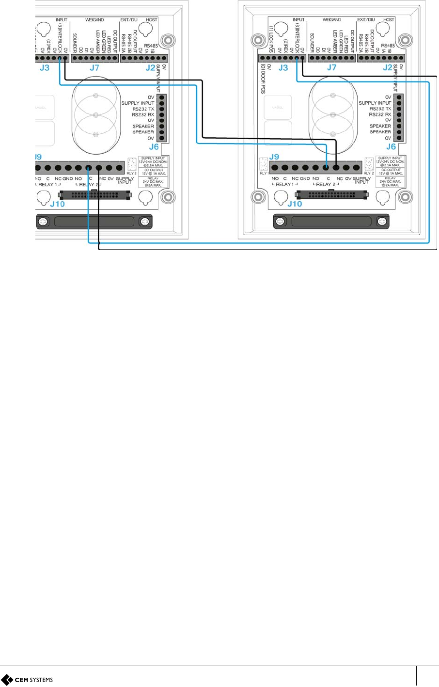
time. This is achieved using a combination of wiring and software configuration. Interlocking
between two terminals is achieved using a simple wiring configuration, however interlocking
more than two terminals requires the use of a third-party logic controller or interposing relay
system.
S700 Installation Manual
83
7.3.1 Wiring two terminals for interlock
Figure 57 Wiring two terminals for interlock
Software configuration for interlock
To configure the software for interlock, complete the following steps:
1. Log on to the AC2000 Floatbar, click Device Configuration, and click Devices.
2. Select the terminal you want to configure and select the Properties tab.
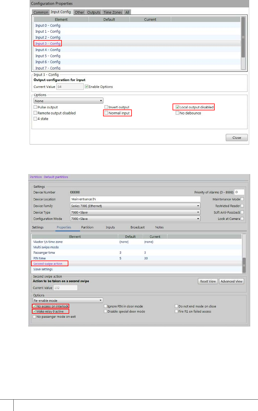
3. Select the Input Config panel and select Input 3, or with DIU select Input B.
S700-IM-0088-1.72
CHAPTER 7 : S700 Operational Modes
84
4. Clear the check box for Normal Input. Ensure the check box for Local output disabled is
selected.
Figure 58 Configuring input 3 for interlock
5. Select the Common tab.
6. Select Second swipe action.
Figure 59 Configuring interlock functionality
7. Select the No access on interlock and Make relay 0 active check boxes.
8. Click Close and click Save on the toolbar of the Devices application.
S700 Installation Manual
85
7.3.2 The interlock process in door mode
Interlock is configured and works the same way in Passenger Mode and Door Mode, with
only a slight change to end functionality.
Figure 60 Interlock locked out display message in door mode
Interlock configuration process
The following outlines the interlock configuration process:
1. The spare outputs of terminals are linked to input 3 of the other interlocked terminals.
2. When input 3 of the terminal is closed the terminal remains idle.
3. When a valid card is swiped at an interlocked terminal, both outputs on the terminal
change to the open state. This drops lock power at the swiped terminal and simultaneously
opens input 3 on any interlocked terminals.
4. Interlocked terminals lock down and display the lockdown message.
5. The interlock function ends when the original swiped door is closed.
7.3.3 The interlock process in passenger mode
The following outlines the interlock process in passenger mode:
1. The spare outputs of terminals are linked to input 3 of the other interlocked terminals.
2. When input 3 of the terminal is closed the terminal remains idle.
3. When a valid card is swiped at an interlocked terminal, both outputs on the terminal
change to the open state. This drops lock power at the swiped terminal and simultaneously
opens input 3 on any interlocked terminals.
4. The swiped terminal displays a countdown screen showing the time that the doors remain
interlocked - that is, Passenger time in the Devices application.
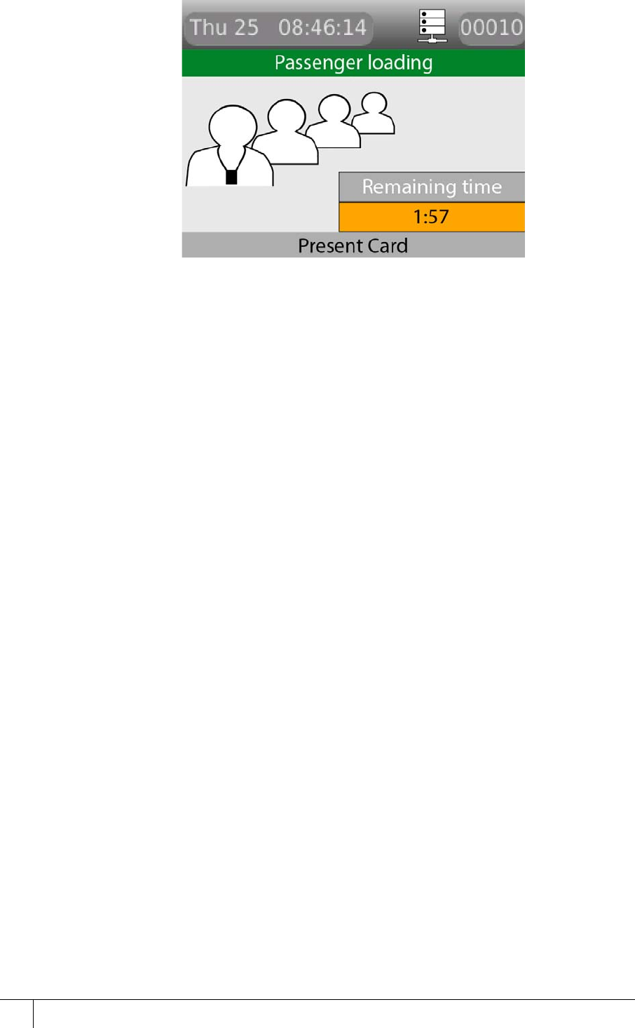
S700-IM-0088-1.72
CHAPTER 7 : S700 Operational Modes
86
Figure 61 Passenger mode countdown on the swiped terminal
5. The interlocked terminals with input 3 now open locks down, preventing access until the
swiped door is closed or the mode ended. Interlocked terminals displays a no-passenger
access message. Normal card access is allowed.
Important: If using a third-party logic controller to control multiple doors, the interlock
principles remain the same. The spare output opens on a valid special usage swipe and input
3 is opened on interlock terminals to trigger lock down.
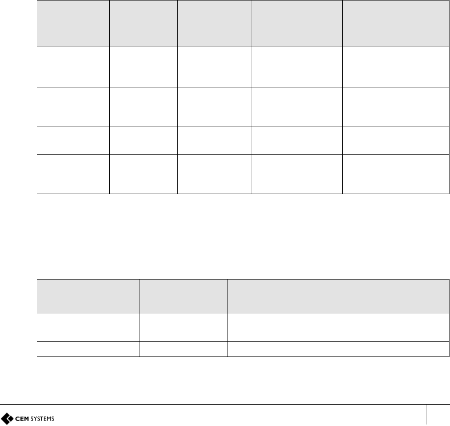
S700 Installation Manual
87
7.4 Equipment mode
A reader configured for Equipment mode must not be used to control a door lock.
The S700 reader controller can be used to enable third-party external equipment by using a
valid card swipe. The S700 enables the equipment; the actual control of the equipment is
carried out by the equipment. An S700 reader and exit combination can be used to enable two
independent pieces of equipment, for example, a generator or conveyor belt.
7.4.1 Setting up Equipment mode
The following outlines the hardware and software configuration for the Equipment mode on the
S700 reader and the AC2000 system.
Connections
The relay outputs on the S700 are used to enable equipment. The relays are low-voltage rated
contacts, so appropriately rated, interposing relays must be used if you want to enable mains-
powered equipment. The relays can either be configured as follows:
• To pulse at the start and pulse at the end of the required enable period
• To activate for the full duration of the required enable period
If necessary, the inputs on the S700 can be used to monitor feedback of the activation state
from the external equipment. Table 32: Equipment mode connections outlines the intended
usage of the available inputs and outputs.
Configuration
The configuration fields that are used by the Equipment enable mode are outlined in Table 33:
Equipment enable Timers.
Equipment
set User
interaction
Connection
on the
Master Purpose Comment
One Master Relay 1 Enable
equipment,
control
Low voltage switch
capable only
One Master Input 0 Equipment
activated, sense Use volt-free
contacts on third-
party equipment
Two Exit Relay 2 Enable
equipment, Two Low-voltage switch
capable only
Two Exit Input 1 Equipment
activated, sense Use volt-free
contacts on third-
party equipment
Table 32: Equipment mode connections
Configuration
item Abbreviation Comment
Lock open time LOT Mode start time, also stop relay time when
LOT2 is zero
Lock open time 2 LOT2 Non-pulsed relay and mode activation time
Table 33: Equipment enable Timers
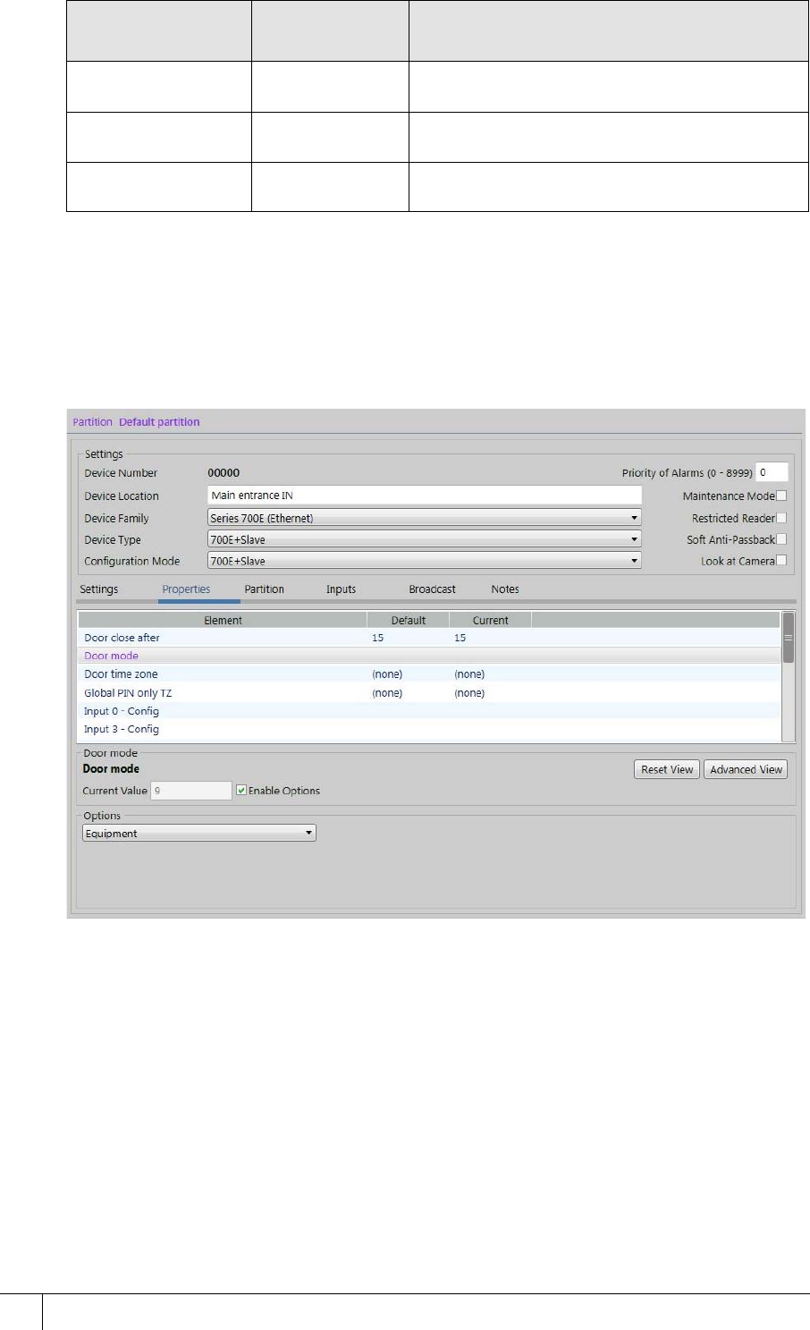
S700-IM-0088-1.72
CHAPTER 7 : S700 Operational Modes
88
Note: The feedback inputs, Input 0 and Input 1, in the table are optional. If they are not to be
used, Input 0 and Input 1 must be disabled.
Selecting Equipment mode in the Devices application
To select and enable Equipment mode for a device, complete the following steps:
Figure 62 Equipment Enable in the Properties tab
1. Launch the Devices application and select the device from the devices tree on the left.
2. Select the Properties tab and click Advanced View.
3. From the Configuration Properties pane, select Door mode.
4. To select Equipment enable mode, use the Options drop-down list to select Equipment.
5. In the Current Value field, set the value, and ensure the Enable Options check box is
selected.
6. Click Close and click Save.
Occupancy swipe
time OST Pulsed mode activation time
Input 0 enable IPE(0) Used to enable activation feedback sense for
Master controller
Input 1 enable IPE(1) Used to enable activation feedback sense for
Exit controller
Configuration
item Abbreviation Comment
Table 33: Equipment enable Timers

S700 Installation Manual
89
Operating Equipment mode
When Equipment mode has been selected for a device, it operates in the following sequence:
1. When you perform a valid card swipe, two operations take place:
i. The relay activates, enabling the third-party equipment. The equipment can be
externally controlled.
ii. The LCD on the S700 reader shows you that the equipment has been activated. In
addition, an alarm is sent: Check-in enabled. There is also a Check-in Disabled and
a Check-in Equipment Fail Alarm.
Figure 63 S700 display: Equipment enabled
2. When the equipment is externally activated, the following takes place:
i. The equipment sends an output to signal that it is in use, causing the sense input to
change state on the S700 reader.
ii. The equipment must be activated within the configured value of Lock open time using
the Properties tab in the Devices application.
iii. The display on the S700 reader changes to the Equipment activated state.
iv. Cost Charging is optional, and can be implemented.
Note: When you implement this, you see a Card Valid Used or Card Valid Unused transaction.
If a card is swiped but the feedback input is not activated, the report shows a Card Valid
Unused transaction. If a card is swiped and the feedback input is activated, the report shows a
Card Valid Used transaction. These transactions can be used for a Cost charging scenario.
Note: As an example, Cost charging is implemented when the airport authority charges an
airline company for the use of a baggage carousel. This action works when an event is sent to
the AC2000 system and that can be used to start cost charging for the use of external, third-
party equipment.
v. While the S700 has the equipment enabled, the equipment can be deactivated and
reactivated repeatedly.
S700-IM-0088-1.72
90
Figure 64 S700 display: Equipment activated
3. When the further usage of the equipment is no longer required, you can do the following:
i. Swipe a valid card to end the operation or allow the timers to run out.
ii. The operator swipes a valid card; this deactivates the S700 relay output.
iii. The AC2000 system sends an event; this stops cost charging for the use of external
equipment.
Figure 65 S700 display: Equipment stopped or Equipment fault
4. If the equipment remains active for longer than the permitted period, the following
happens:
i. The S700 deactivates automatically; this deactivates the S700 relay output.
ii. A Check-in Disabled alarm is sent. The AC2000 system stops cost charging for the
use of external equipment.
5. When the equipment has been stopped, the S700 returns to its idle state ready to start a
new sequence.
S700 Installation Manual
91
Appendix 1 Updating Firmware
Updating the S700 terminal firmware, device defrosting, is accomplished by using the AC2000 web
pages to load the firmware pack on to the terminal and manually updating the terminal.
Note: This process must only be carried out by an AC2000 administrator with the relevant permissions.
Accessing the System Configuration Menu
To access the configuration menu, complete the following steps:
1. On the terminal keypad, quickly tap the right function key at least three times.
2. When prompted to enter passcode type 67670000.
Figure 66 Accessing the configuration menu
Note: After the AC2000 system setup is complete, the pass code is 67670000, where 0000 is
the code set by the system. The final four digits of this PIN are configurable for the terminal in
the Devices application. For more information on configuring the passcode, see section 6.3
Accessing the system configuration menu, on page 67.
3. Select Device Status from the configuration menu by pressing the 3 key on the terminal
keypad.
The firmware version is displayed at the top of the screen. Check for the number beside
the F/W Version heading.
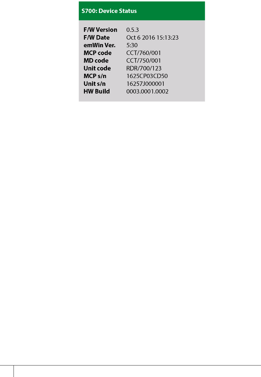
S700-IM-0088-1.72
92
Checking the firmware version of the terminal
To check the status of your device quickly, complete the following step:
• Tap the left function key quickly at least three times. The appears with information on the
firmware on the S700 terminal, as shown in Figure 66 Accessing the configuration menu.
Figure 67 Device status
Loading the firmware onto the terminal
To load the firmware onto the terminal, complete the following steps:
1. Obtain the firmware pack from CEM Systems and save to an accessible location on the
network.
2. Log into the web pages by opening a web browser.
3. Into the browser, enter the Server IP Address, for example:
https://192.168.1.10
If the IP address has been changed from the default, enter the new IP address.
4. Enter the username and password.
5. Click Login.
6. Select AC2000 WEB, select Reader Setup, and select Device Defrost.
7. Click Choose file and select the S700 device image file (.z70) that is to be loaded.
Note: This image is provided by CEM Support and must be saved in a secure location.
8. Click Upload
9. Click OK.
A message appears similar to the following:
Initiating defrost to device:XXXX with firmware file:<filename>
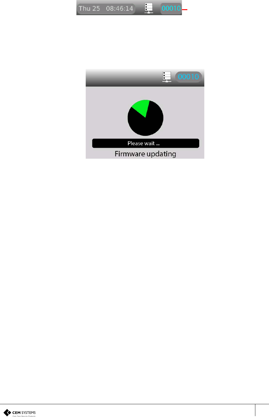
S700 Installation Manual
93
Updating the terminal
When the terminal has received the firmware file, the reader address is displayed in the colour
cyan instead of white.
Figure 68 Cyan reader address
To update the terminal, complete the following steps:
1. Access the System Configuration Menu of the terminal.
2. Press the number 8 on the keypad. This opens the Firmware Upgrade menu.
3. Select Apply.
Figure 69 Upgrading the terminal firmware
The reader updates and reboots.
Note: The reader goes offline for up to 30 seconds while the upgrade takes place.
Reader address
displayed in cyan

S700-IM-0088-1.72
94

S700 Installation Manual
95
Appendix 2 Broadcast and Timezone Priorities
A state machine is used to determine the priority that different events such as broadcast and timezone
changes have on the terminal. The order is listed in descending priority, which is outlined in the
following way:
1. Broadcast open
2. Interlock input
3. Locked out TZ (timezone)
4. Door override TZ (timezone)
5. Card only TZ (timezone)
6. PIN only TZ (timezone)
Example
If there is an overlap between the Locked out TZ and the Card only TZ, the Locked out TZ
will take priority due to it being higher up the list. When the Locked out TZ ends the Card only
TZ takes over.
Regardless of which state the terminal is in, a Broadcast open opens the door, overriding all
other options.
Note: For more information on timezones, see the AC2000 Setup Guide, and for information
about broadcasts, see the AC2000 Operator Guide.

S700-IM-0088-1.72
96
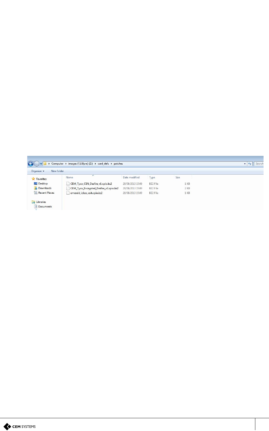
S700 Installation Manual
97
Appendix 3 Loading card definitions
In order for AC2000 to correctly process the information encoded on the smart cards, the correct card
definitions must be loaded onto the CDC. These are loaded using the AC2000 Web pages.
1. Log into the AC2000 client software. This is done to allow access to the definition files on
the CDC.
2. Log into the web pages by opening a web browser.
3. Enter the Server IP Address, for example:
https://192.168.1.10
If the IP address has been changed from the default, enter the new IP address.
4. Enter the username and password.
5. Click Login.
6. Select AC2000 WEB, select System, and click Software Update.
7. Click Browse and navigate to Z:\\card_defs\patches.
8. Select the device image file (.cpio.bz) that is to be loaded.
Figure 70 Card definition file list
9. Click Upload
10. Click OK.

CEM Systems
195 Airport Road West
Belfast
BT3 9ED
United Kingdom
Tel: +44(0)2890 456767
