L3 Technologies 0ATN01 Aid to Navigation (AtoN) AIS User Manual title
L-3 Communications Aid to Navigation (AtoN) AIS title
Contents
- 1. user install
- 2. additional info
- 3. Manual
user install

P/N: 165M0829-00August 7/08
Rev. 7
L-3 COMMUNICATIONS
AID TO NAVIGATION
(AtoN)
INSTALLATION & OPERATION MANUAL
AtoN PART NUMBERS:
ATN01--100--00
ATN01--100--01
ATN01--100--02
ATN01--100--03
ATN01--300--00
ATN01--300--01
ATN01--300--02
ATN01--300--03
ATN01--301--00

Marine Systems
Aviation Recorders
AtoN Installation & Operation Manual
Rev. 7
August 7/08
165M0829-00
Page ii
L--3
A
toN I&O Manual 165M0829-00
Rev. 7
August 7/08
EXPORT CONTROL STATEMENT AIS TECHNOLO-
GY / DATA:
“This technical data is controlled under the Export Ad-
ministration Regulations ECCN 5E992, and may not be
exported to a Foreign Person, either in the U.S. or
abroad, without the proper authorization of the U.S. De-
partment of Commerce.”
This manual contains date sensitive information.
To verify the latest revision level of this manual,
visit our document download site at
http://www.L-3ar.net.
ECopyright 2008 by L-3 Communications.
All rights reserved. No part of this manual may be re-
produced or utilized in any form or by any means, elec-
tronic or mechanical, including photocopying, record-
ing, or by information storage and retrieval system,
without permission in writing.
Inquiries should be addressed to:
L-3 Communications
Aviation Recorders Publications
Vendor Code: 06141
P. O. Box 3041
Sarasota, Florida 34230

Marine Systems
Aviation Recorders
AtoN Installation & Operation Manual
Rev. 7
August 7/08
165M0829-00
Page iii
GENERAL
This product and related documentation must be reviewed for familiarization with safety
markings and instructions before operation.
This board was constructed in an ESD (electro–static discharge) protected environment. This is
because most of the semiconductor devices used in this board are susceptible to damage by static
discharge.
Depending on the magnitude of the charge, device substrates can be punctured or destroyed by
contact or mere proximity of a static charge. The results can cause degradation of device perfor-
mance, early failure, or immediate destruction.
These charges are generated in numerous ways such as simple contact, separation of materials,
and normal motions of persons working with static sensitive devices.
When handling or servicing equipment containing static sensitive devices, adequate precautions
must be taken to prevent device damage or destruction.
Only those who are thoroughly familiar with industry accepted techniques for handling static sen-
sitive devices should attempt to service circuitry with these devices.
In all instances, measures must be taken to prevent static charge build–up on work surfaces and
persons handling the devices.

Marine Systems
Aviation Recorders
AtoN Installation & Operation Manual
Rev. 7
August 7/08
165M0829-00
Page iv
THIS PAGE IS INTENTIONALLY LEFT BLANK.

Marine Systems
Aviation Recorders
Rev. 7
August 7/08
165M0829--00
Page 1--1
AtoN Introduction
1.1. General
The Aids to Navigation (AtoN) is an Automatic Identification System (AIS) transmitter
that is fully compliant to the technical specifications defined by the IMO and outlined
in ITU.R.M 1371-1. The transmitter is designed to be installed in weather and navi-
gation buoys with no periodic maintenance required. The transmitter employs the
latest radio frequency and FATDMA technology to provide a high performance, auto-
mated, and reliable identification system. The transmitter is a fully automated sys-
tem, which ties into the buoy’s navigational and/or weather monitoring instrumenta-
tion to provide automatic transmission of navigational and meteorological data (de-
pendent on the installation).
The Transponder is a fully automated system. This means that once it is installed
and turned on, no maintenance is required to keep it operational.
The L--3 ProTec Inland Waterways/Class A Automatic Identification System
transponder is manufactured in Sarasota, Florida, United States of America, pursu-
ant to ISO 9000.
1.1.1. System Overview
The AtoN is an Aids to Navigation System fully compliant with the IMO specifications
defined in IMO MSC.74(69) Annex 3, IEC 62320--2-2, and ITU.R M.1371-3.Withthe
addition of the FATDMA controllers, the AtoN provides a cost-effective AIS solution,
which will meet the needs of any waterway required to transmit AtoN data. The com-
pact, single-box design allows the AtoN to be easily incorporated into any buoy lay-
out thus simplifying installation and cabling requirements.
The AtoN has been designed as maintenance-free unit, which makes extensive use
of surface mount technology (SMT). The repair of printed wiring assemblies (PWAs)
containing SMT components requires specialized factory equipment, training, and
techniques, therefore, such PWAs are not field-repairable.
As a result, maintenance philosophy for the AtoN is replacement of failed assemb-
lies. In the case of the AtoN, the entire unit should be sent back to the factory, in the
unlikely case of a failure.
Attempts by anyone but an authorized L--3 representative to repair the AtoN will void
the warranty.

Marine Systems
Aviation Recorders
Rev. 7
August 7/08
165M0829--00
Page 1--2
For repair service, call or email to obtain an RMA # or Form:
L-3 Communications, Aviation Recorders
6000 E. Fruitville Road
Sarasota, FL 34232 USA
Attn: Repair Department
Tel: (941) 377-5558
Fax #: (941) 377-5585
1.1.2. References
IMO Resolution MSC.74(69), Annex 3, Recommendation on Performance Standards
for a Universal Shipborne Automatic Identification Systems (AIS)
International Telecommunications Union Sector for Radio Communications (ITU-R)
Recommendation M.1371-3, Technical Characteristics for a Universal Shipborne
Automatic Identification System Using Time Division Multiple Access in the Maritime
Mobile Band.
IEC 61993-2 Edition1, Maritime Navigation and Radio communication Requirements
- Automatic Identification Systems (AIS) - Part 2: Class A shipborne Equipment of
the Universal Automatic Identification System (AIS) - Operational and Performance
Requirements, Methods of Test and Required Test Results
IEC 60945 Edition 4, Maritime Navigation and Radio communication Equipment and
Systems - General Requirements - Methods of Testing and Required Test Results.
IALA Recommendation on AIS Shore Stations and Networking Aspects Relating to
the AIS Service, Edition 1.0, September 5, 2002
IEC 61162-1 Edition 1.0, Maritime Navigation and Radio communication Equipment
and Systems - Digital Interfaces - Part 100: Single Talker and Multiple Listeners
IEC 61162-2 Edition 1.0, Maritime Navigation and Radio communication Equipment
and Systems - Digital Interfaces - Part 100: Single Talker and Multiple Listeners,
High-Speed Transmissions
1.1.3. Acronyms
ABM Addressed Binary Message
ABK Acknowledgment Message
ACA AIS Channel Assignment
ACK Acknowledgment Message
ARM Advanced RISC Machine
ARPA Automatic Radar Plotting Aid
BBM Broadcast Binary Message
COG Course Over Ground
DGPS Differential Global Positioning System
DSP Digital Signal Processor

Marine Systems
Aviation Recorders
Rev. 7
August 7/08
165M0829--00
Page 1--3
FATDMA Fixed Access Time Division Multiiple Access
GGA Global Positioning Fix Data
GLL Geographic Position, Latitude/Longitude
GNSS Global Navigation Satellite System
GPS Global Positioning System
GSA GPS DOP and Active Satellites
GSV GPS Satellites in View
HDG Heading, Deviation & Variation
HDT Heading, True
IEC International Electrotechnical Commission
IMO International Maritime Organization
LRF Long Range Function
LFI Long Range Interrogation
MMSI Maritime Mobile Service ID
NMEA National Marine Electronics Association
NV Non--Volatile
PLL Phase Locked Loop
RAIM Receiver Autonomous Integrity Monitoring
RATDMA Random Access Time Division Multiiple Access
RF Radio Frequency
RMC Recommended Minimum Data for GPS
ROT Rate of Turn
SOG Speed Over Ground
SOTDMA Self Organized Time Division Multiple Access
SSD Station Static Data
TDS Target Display Software
TXT Status/Indication Message
VBW Dual Ground/Water Speed
VDL VHF Data-link Other Vessel Message
VDM VHF Data-link Message
VDO VHF Data-link Own-vessel Message
VSD Voyage Static Data
VSWR Voltage Standing Wave Ratio
VTG Track Made Good and Ground Speed
ZDA Date and Time

Marine Systems
Aviation Recorders
Rev. 7
August 7/08
165M0829--00
Page 1--4
1.2. Technical Specifications
Standards IMO MSC.74(69) Annex 3, IEC 61993-2 Ed. 1, ITU.R.M.1371-1, IALA
A-126
TDMA Transmitter
TX Frequency: 156.025 MHz - 162.025 MHz
Transmitter Power: 12.5 W max.
Channel Bandwidth: 25 kHz
Output
Message 6, Message 21 as defined in ITU.R.M.1371-1
Power Supply
12 VDC nominal
Power Consumption
Message 21 (FA) every 3 minutes for 30 minutes (10 full cycles):
FAverage Instantaneous Current: 14.2 mA (Vin = 12.0 Vdc)
FAverage Instantaneous Power: 170 mW
Message 21 (RA) every 3 minutes for 30 minutes (10 full cycles):
FAverage Instantaneous Current: 125 mA (Vin = 12.0 Vdc)
FAverage Instantaneous Power: 1500 mW
Power usage in continuous receive mode:
FAverage Instantaneous Current: 323 mA (Vin = 12.0 Vdc)
FAverage Instantaneous Power: 3880 mW
Environment
IEC 60945 Ed. 4 for Unprotected Environment
Frequency
VHF Marine Band

Marine Systems
Aviation Recorders
Rev. 7
August 7/08
165M0829--00
Page 1--5
1.3. AtoN Description
1.3.1. Compact Design
The completely self-contained L-3 AtoN has outside dimensions of 5.24” W (133
mm.) x 4.73” H (120 mm.) x 4.73” D (120 mm.). It is easily mounted inside the buoy
using a flush-mount bracket.
MODEL ATON
AIS FOR AIDS TO NAVIGATION SYSTEMS
PART NUMBER MATRIX
ATN01–XXX–XX
CONFIGURATION
TYPE 1 (TRANSMIT ONLY) 1.........
TYPE 2 (LIMITED RECEIVER) 2......
TYPE 3 (FULL ATON) 3..............
FEATURES
00 BASIC......
01 MOUNTING FLANGE......
02 RF LIGHTNING PROTECTION......
03 MOUNTING FLANGE & RF......
LIGHTNING PROTECTION
INTERNAL DESIGNATOR
Figure 1--1. AtoN Part Number Matrix

Marine Systems
Aviation Recorders
Rev. 7
August 7/08
165M0829--00
Page 1--6
THIS PAGE IS INTENTIONALLY LEFT BLANK.

Marine Systems
Aviation Recorders
Automatic Identification System
Page 2--1
Rev. 7165M0829--00
August 7/08
AtoN Mounting & Connections
ISOMETRIC VIEW
PART NUMBERS:
ATN01-1-00-00
ATN01-1-00-02
ATN01-3-00-00
ATN01-3-00-02
ATN01-3-01-00
Figure 2--1. AtoN
ISOMETRIC VIEW
PART NUMBERS:
ATN01-1-00-01
ATN01-1-00-03
ATN01-3-00-01
ATN01-3-00-03
Figure 2--2. AtoN with Mounting Plate

Marine Systems
Aviation Recorders
Automatic Identification System
Page 2--2
165M0829--00Rev. 7
August 7/08
P/N: 115M0743-00
Figure 2--3. AtoN Mounting Plate
Dimensions and Mounting Hole Pattern

Marine Systems
Aviation Recorders
Automatic Identification System
Page 2--3
Rev. 7165M0829--00
August 7/08
Figure 2--4. AtoN Outline & Dimensions

Marine Systems
Aviation Recorders
Automatic Identification System
Page 2--4
165M0829--00Rev. 7
August 7/08
Figure 2--4. (Continued) AtoN Outline & Dimensions

Marine Systems
Aviation Recorders
Automatic Identification System
Page 2--5
Rev. 7165M0829--00
August 7/08
Figure 2--5. AtoN Connections
Marine Systems
Aviation Recorders
Automatic Identification System
Page 2--6
165M0829--00Rev. 7
August 7/08
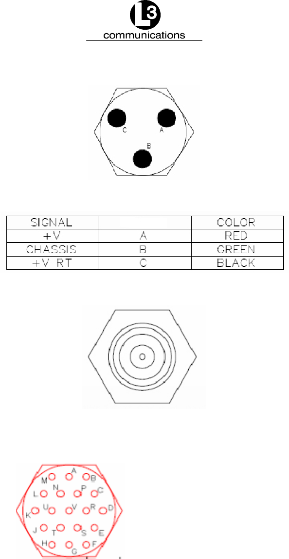
The power cable, Part Number 024M0926--00, is supplied by L--3.
Figure 2--6. Power Connection Pin Out
Figure 2--7. GPS Connection Pin Out
GND*
PIN
P
V
U
CONNECT
RSVD
RSVD
R
L
K
G
GND
RSVD
RSVD
RSVD
T
S
A
B
I E C --- T X *
I E C --- R X *
SYNC+
S Y N C ---
Figure 2--8. Sensor Data Connection Pin Out**
The Sensor Data cable, Part Number 024M0841--00, is supplied by L--3.
*Used to connect to the AtoN IEC/serial port to a DB9 connector

Marine Systems
Aviation Recorders
Automatic Identification System
Page 2--7
Rev. 7165M0829--00
August 7/08
**Signals names are with respect to the AtoN (RS--232).
Installing the VHF Antenna
Installation of a VHF antenna is as important to reliable communications as the
transceiver itself. It is recommended that a high quality antenna be purchased from
an established source and that all manufacturer’s instructions be followed with
particular attention to cable routing and connector installation. Some important
considerations in antenna installation are:
FIn general, VHF antennas should be located as high as practical on the
buoy and separated as much as possible from each other.
FThe VHF antenna should be placed in an elevated position with a mini-
mum of 2 meters clearance from any construction that is made with con-
ductive material. In addition, it should not be installed close to any large
vertical obstruction, and the VHF antenna should have a 360°line of sight
to the horizon.
To install the VHF antenna, perform the following:
(Refer to Figure 2--9.)
(1) Position the antenna mounting bracket on a rigid and structurally sound sur-
face.
(2) Install the antenna on the antenna mount.
NOTE: Use only high quality RG213/RG214 coaxial cable and keep
cable length as short as possible to reduce signal attenua-
tion.
(3) Run the coaxial cable from the antenna to the transponder location.
(4) Trim cable to length leaving a few inches slack at the transponder.
(5) Attach the connectors to the end of the coaxial cable.
(6) Connect the cables to the transponder. Soldering the connection is
recommended.

Marine Systems
Aviation Recorders
Automatic Identification System
Page 2--8
165M0829--00Rev. 7
August 7/08
Installing the GPS Antenna
The correct installation of a GPS antenna is crucial to the operation of the trans-
ponder because the internal transmission synchronization relies on the accuracy of
the time signal obtained from the GPS. It is recommended that a high quality GPS
antenna be purchased from an established source and that all manufacturer’s
instructions be followed with particular attention to cable routing and connector
installation. Some important considerations in GPS antenna installation are:
FGPS antennas should be located to provide a clear, unobstructed view of
the sky.
FGPS signals can also be affected negatively by VHF transmissions, and
the GPS antenna should be positioned at least 3 meters from the VHF
antenna, if possible.
FThe GPS antennas can be flat mounted onto any surface but it is recom-
mended that it be elevated as high as possible to prevent ice or spray
from negatively impacting the signal reception.
To install the GPS antenna, perform the following:
(Refer to Figure 2--9)
(1) Position the antenna mounting bracket and/or antenna mast on a rigid and
structurally sound surface.
(2) Install the antenna on the antenna mount.
NOTE: Use only high quality RG213/RG214 coaxial cable and keep cable
length as short as possible to reduce signal attenuation.
(3) Run the coaxial cable from the antenna to the transponder location through an
existing throughhull.
(4) Trim cable to length leaving a few inches slack at the transponder.
(5) Attach the connectors to the end of the coaxial cable.
(6) Connect the cable to the transponder. Soldering the connection is
recommended.

Marine Systems
Aviation Recorders
Automatic Identification System
Page 2--9
Rev. 7165M0829--00
August 7/08
Figure 2--9. AtoN Transponder Antenna Diagram

Marine Systems
Aviation Recorders
Automatic Identification System
Page 2--10
165M0829--00Rev. 7
August 7/08
THIS PAGE IS INTENTIONALLY LEFT BLANK.

Marine Systems
Aviation Recorders
Rev. 7
August 7/08
165M0829--00
Page 3--1
AtoN Configuration
3.1. Introduction
The AtoN may transmit messages 6 and/or 21 as specified by ITU--R M. 1371--1.
Message 6 is defined as an Addressed Binary Message (ABM). It can be variable
in length depending on the amount of binary data and can consist of 1 to 5 slots.
Data from a message 6 may contain a status report on the health of the buoy, or
other information. As implied in the name, the message must be addressed. That
is, it must contain the appropriate destination MMSI of the base station that is to re-
ceive the transmission.
Message 21 is defined as an Aids-to-Navigation Report. This message is usually
transmitted every 3 minutes and contains the origination MMSI, name of the AtoN (if
applicable), type of AtoN (fixed or floating), position of the AtoN and the positional
accuracy. The position information is derived from the on--board GPS receiver that
is internal to the AtoN. As well as the deriving position, the GPS receiver is used as
the basis for all transmission timing on the VDL. Unlike the message 6, this report is
meant to be seen by all AIS transponders.
3.2. Configuration
The transmit functions of the AtoN must be configured prior to installation. The con-
figuration parameters specify what messages are transmitted over the air, how often
the transmissions occur and what slot on the VHF data link (VDL) they are trans-
mitted on.
NOTE: All message assignments and intervals must be defined and ap-
proved by the appropriate competent authority where the AtoN
is to be installed.
Configuration is accomplished via a personal computer (PC) using a simple terminal
emulator. An AtoN configuration cable is connected from the PC’s serial port to the
serial interface connector of the AtoN. In this example, WindowstHyperTerminal is
used. Connect the PC to the AtoN using the configuration cable.
3.3. Firmware Update
In order to update AtoN firmware, the following is required:
FPower Cable: For details on the pin out, refer to Figure 2--6.
FCommunications Cable: For details on the pin out, refer to Figure 2--8.

Marine Systems
Aviation Recorders
Rev. 7
August 7/08
165M0829--00
Page 3--2
FFirmware Update Package
3.4. Overview
The AtoN contains two processors, an ARM and a DSP. The ARM has complete
control over the DSP power and reset lines. The DSP runs the RF subsystem, but
only when the ARM has enabled it to do so.
When the AtoN is up and running, the ARM Debug Unit (DBGU) serial port is used
for Trace message output and shows ARM operational status and information. This
interface also functions as a menu-based configuration and command and control
channel for the unit, with a set of built-in “hot key” sequences for initiating various
operations. The interface to this channel is typically a serial console program such
as HyperTerminal. The ARM DBGU channel runs at 115200 Baud, 8 Data Bits, and
No Parity.
NOTE: The AtoN’s sleep state may interfere with the configuration pro-
cess.
When left unattended, the AtoN unit may go into a “sleep” state (enter Standby
Mode). As of Rev 1.14H of the ARM software, this is the case for both Type 1 and
Type 3 units. Standby Mode can interfere with running tests, loading code and con-
figuring the AtoN unit. The AtoN can be prevented from entering Standby Mode by
leaving the GPS antenna disconnected. The AtoN will not enter standby mode if it
has no time input that the GPS would normally provide.
As of Rev 1.14H of the ARM software, the “Standby Enable” can be toggled on and
off using the ^P^P sequence (Ctrl Key with P, twice) at the ARM console interface.
In order to run tests on the RF subsystem it is necessary that the DSP be powered
up and released from Reset. This is completely under control of the ARM processor,
making it impossible to run tests on the DSP unless the ARM is cooperating. Use the
“T-2-E” sequence at the ARM console to ensure that the DSP is running.
The ARM DBGU serial interface also provides some user control in the form of Menu
and command entry. There are three menus currently implemented, a System Con-
figuration Menu, a General Configuration Menu and a Test Menu.
The System Configuration Menu is invoked by typing ‘S’, the General Configuration
Menu is invoked by typing ‘C’, and the Test Menu is invoked by typing ‘T’.
On entry to any of these Menus, normal AtoN operation is terminated. Since the op-
erations available in the Setup, Test and Config menus can leave the AtoN in an
indeterminate state, a Reboot always follows the exit from these menus. This is au-
tomatic upon termination of Menu activity. The operations associated with these Me-
nus are discussed further in subsequent sections of this document.

Marine Systems
Aviation Recorders
Rev. 7
August 7/08
165M0829--00
Page 3--3
Failure Modes
For Transmission Fault/Disabled Antenna:
A disabled antenna is detected by the AtoN DSP as an antenna with a high VSWR
during the transmission of a message. If a high VSWR is detected, the DSP stops
transmission before a message completes transmission.
For Reception Fault:
The AtoN uses a frequency synthesizer incorporating a digital PLL. If both receivers
are locked, a Lock Detect status signal is sent indicating the receivers are function-
ing. If either or both receivers fail to lock then the Lock Detect status indicates a fault
and RATDMA transmissions are stopped.
3.5. Resetting the AtoN from the ARM HyperTerm Console
When the AtoN is operational and Trace messages are being displayed on the ARM
HyperTerm console, the unit can be Reset at any time by holding the Ctrl key and
typing a pair of ‘C’ characters in succession. This avoids the need to cycle power in
order to restart the AtoN.
3.6. ARM Code Update
If the Baseband Board has not been updated, it may still be loaded with Micromoni-
tor in Flash. In this case, the ARM code must be updated as a first step. In order to
do this, please follow the procedure below.
NOTE:Note that this method of updating the ARM code will work
whether Micromonitor is in Flash or not. However, it is the
only method that will work for loading an ARM standalone
binary image if Micromonitor is still resident.
(7) The ARM DBGU port should be connected to HyperTerm at 115200 Baud.
(8) The BMS jumper must be installed on the Baseband Board, and power applied.
The BMS jumper is installed on the Baseband Board at PL10, between pins 13 and
14.
(9) If the BMS jumper connection is made, and power is applied to the AtoN, the Hy-
perTerm console should display ‘C’ characters at approximately one per second.
Once the ‘C’ characters are being displayed at the HyperTerm console, the ARM
code update can begin.
(10) On the HyperTerm menu pull--down bar, select Transfer-->Send File.

Marine Systems
Aviation Recorders
Rev. 7
August 7/08
165M0829--00
Page 3--4
(11) In the Protocol box of the subsequent pop--up window, select Xmodem.
(12) Use the “Browse” button to locate the ARM binary images. Typically, these are con-
tained in a folder called “Aton Images”. Select the “SerBoot.bin” file by double---
clicking on it in the file list (or single--click and hit the “Open” button).
(13) Hit the “Send” button in the “Send File” window. This will start the transfer.
(14) On completion of the transfer the ‘C’ characters will start again. At this time, locate
the ARM executable binary image in the same folder as the “SerBoot.bin” file. An
example would be AtoN_1_03.bin. This name corresponds to Rev 1.03 of the ARM
code. Typically, one would select the file with the highest version number, but there
may be situations where an older version is to be loaded. Note that the Micromoni-
tor image could also be sent at this point instead of the AtoN binary image. The
Micromonitor image is contained in a file named “CSB_637.bin” and represents the
original Micromonitor image as contained on the Cogent CSB637 development
boards that preceded the Baseband board.
(15) Select the binary file to be loaded by double-clicking on it in the file list (or single--
click and hit the “Open” button).
(16) Next hit the “Send” button in the “Send File” window. This will start the transfer of
the binary image.
(17) On completion of the transfer the ‘C’ characters will start again. Remove the BMS
jumper and power the board up again. The unit should boot normally and Trace
messages will appear in the HyperTerm window. Note that if an ARM standalone
image was loaded, the HyperTerm connection must be at 115200 Baud (the same
as the download). However, if the Micromonitor image was restored for some rea-
son (not typical) the HyperTerm connection must be set to 38400 Baud.
3.7. Clearing the NV Content
Some situations may require the entire NV configuration be cleared. This is a recom-
mended procedure when an ARM software update is performed because the stored
NV configuration structures may not be compatible with the code that has been
loaded.
Clearing the NV content does not cause the Unit Type or Serial Number to be lost.
This operation restores the NV to a fresh state. This is done from the ARM Hyper-
Term console while Trace messages are being displayed.
Hold the Ctrl key, and type the sequence, “NVERAS”. A message should appear
indicating that the NV was erased. This will erase any transmit schedule that had
been created, and will set all NV values to the appropriate defaults for the configured
Unit Type on the next startup.
Marine Systems
Aviation Recorders
Rev. 7
August 7/08
165M0829--00
Page 3--5
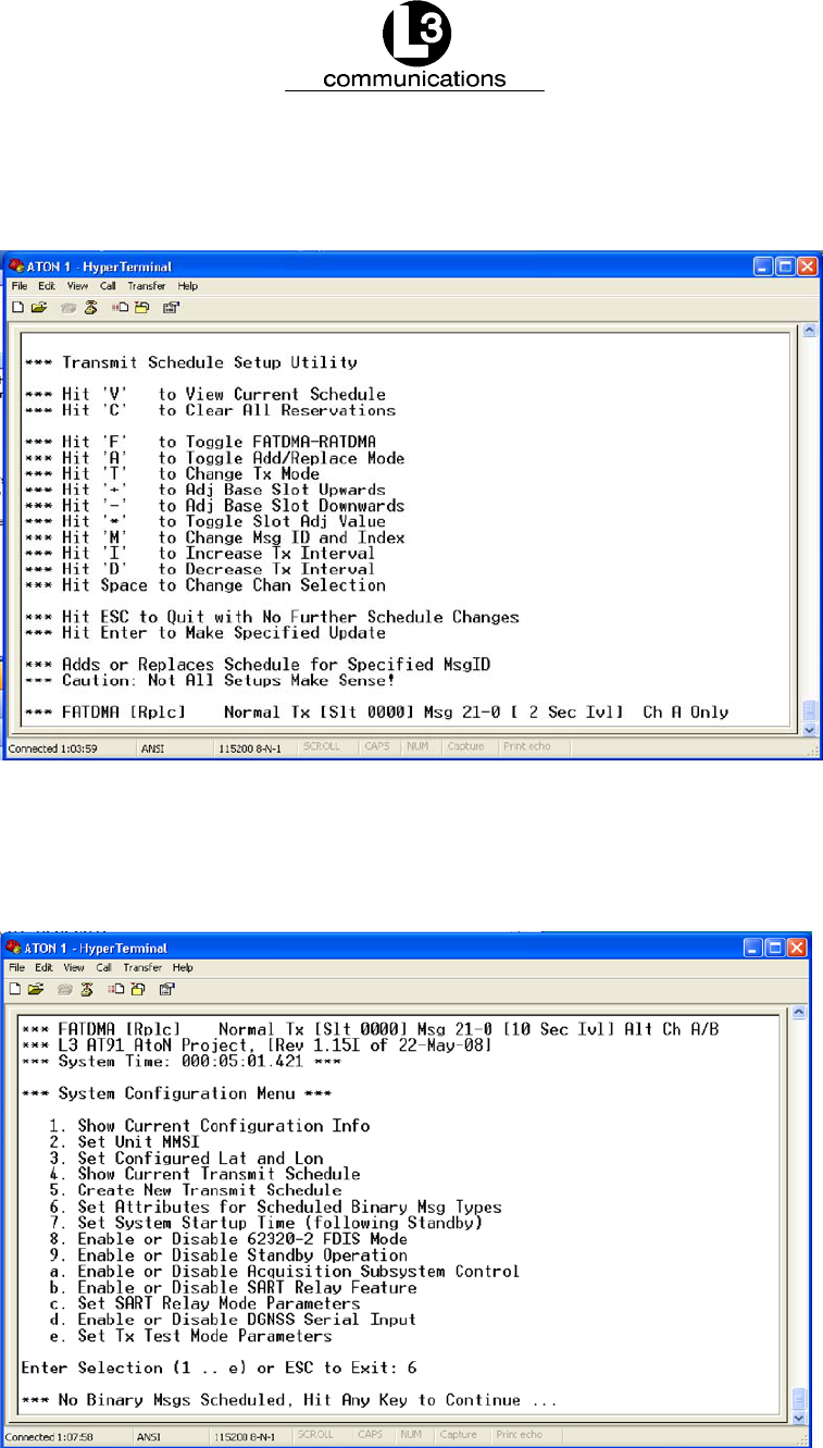
3.8. Setting Transmit Schedule Using Scheduling Utility
It is not necessary to use the Startup Dialog to create a transmit schedule. A sched-
uling utility is now part of the General Configuration Menu. This can be invoked at
any time by pressing the ‘C’ key, then selecting item 3.
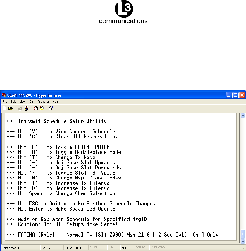
Figure 3--10. Transmit Schedule Setup Utility
Figure 3--10 shows the control choices for building transmit schedules. The line at
the bottom of the screen shows the attributes for a new schedule entry that will be
created if the User hits the ENTER key.
Hitting the “V” key displays the current view of the schedule.
Hitting the “C” key clears all reservations.
Hitting the ‘F’ key toggles whether the new schedule item will be FATDMA or RATD-
MA.
Hitting the ‘A’ key toggles whether the entry will Add or Replace to any entries for the
selected Message ID and Index.
Hitting the ‘T’ key toggles the Tx Mode between Normal and Back to Back transmis-
sions. This option is typically set to “Normal”, but special test scenarios might require
“Back to Back” transmissions.

Marine Systems
Aviation Recorders
Rev. 7
August 7/08
165M0829--00
Page 3--6
Hitting the SHFT and ‘+’ (plus) key increases the value of the “base” or “anchor” slot
upwards by 10 for the scheduled transmission.
Hitting the ‘--’ (minus) key decreases the value of the “base” or “anchor” slot down-
wards by 10 for the scheduled transmission.
Hitting the ‘*’ key will toggle the slot adjustment to a value between 10 and 1. This
allows for fine control over the base slot.
Hitting the ‘M’ key will cycle through the Message ID and Index as choices for the
next field.
Hitting the ‘I’ key increases the transmit interval value for the scheduled transmis-
sion.
Hitting the ‘D’ key decreases the transmit interval value for the scheduled transmis-
sion.
Hitting the Space Bar will cycle through the choices for the final field and change the
Channel Selection.
Hitting the ESC button returns the screen to the main “System Configuration Menu.”
Hitting the ENTER button displays a message to “Hit Any Key to Continue...” Hit
ENTER again, and the Transmit Schedule Setup Utility screen appears.
Marine Systems
Aviation Recorders
Rev. 7
August 7/08
165M0829--00
Page 4--1
System Configuration Menu
4.1. System Configuration Menu
The features of the AtoN “System Configuration Menu” are described in this section.
A more detailed explanation of each feature, how it is configured, and its parameters
will be provided in a future version of this manual.
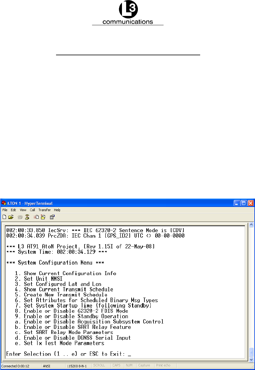
To access the “System Configuration Menu” for the ARM, press “C” in the ARM
HyperTerminal while it is transmitting data normally. The window appears, as shown
below.
If a different window is open, press “ESC,” so a “Hit Any Key to Reboot” message
appears. Press any key, so the system reboots. Press “C” to open the System Con-
figuration Menu.
To configure a specific feature, type in the number or letter associated with it in the
menu. This opens self--explanatory options at the bottom of the screen.
Figure 4--11. System Configuration Menu
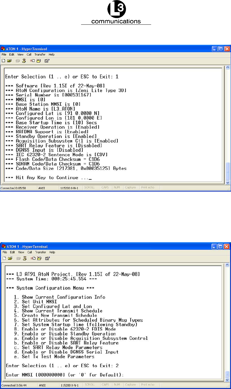
When “1” is entered in the “System Configuration Menu,” the “Current Configuration
Information” screen appears with a summary of the AtoN’s existing setup. The “Cur-
rent Configuration Information” screen is shown below.
Marine Systems
Aviation Recorders
Rev. 7
August 7/08
165M0829--00
Page 4--2
Figure 4--12. Current Configuration Information Screen
To set the MMSI, enter “2” in the main “System Configuration Menu,” and the option
shown below appears at the bottom of the screen.
Figure 4--13. MMSI Mode

Marine Systems
Aviation Recorders
Rev. 7
August 7/08
165M0829--00
Page 4--3
To set the Latitude and Longitude, enter “3” in the main “System Configuration
Menu” and the option appears at the bottom of the screen, as shown below.
Figure 4--14. Configure Latitude and Longitude
To view the current transmit schedule, enter “4” in the main “System Configuration
Menu,” and the screen shown below summarizes the information at the bottom.
Figure 4--15. Configure Transmit Schedule
Marine Systems
Aviation Recorders
Rev. 7
August 7/08
165M0829--00
Page 4--4
To set the transmit data, enter “5” in the main “System Configuration Menu,” and a
screen opens with the features and descriptions shown below.
Figure 4--16. Transmit Schedule Setup Utility
To set attributes for schedule binary messages, enter “6” in the main “System Con-
figuration Menu,” and the option appears at the bottom of the screen.
Figure 4--17. Set Attributes for Scheduled Binary Message Types

Marine Systems
Aviation Recorders
Rev. 7
August 7/08
165M0829--00
Page 4--5
To set the system startup time, enter “7” in the main “System Configuration Menu,”
and the screen shown below displays options to increase or decrease the time.
Figure 4--18. Setting System Startup Time
To set the 6320--2 FDIS Mode, enter “8” in the main “System Configuration Menu”.
The features appear in the screen, as shown below.
Figure 4--19. Setting 6320--2 FDIS Mode

Marine Systems
Aviation Recorders
Rev. 7
August 7/08
165M0829--00
Page 4--6
To change the standby mode, enter “9” in the main “System Configuration Menu,”
and the screen shown below displays the option.
Figure 4--20. Controlling Standby Operation
To control the acquisition subsystem, enter “a” in the main “System Configuration
Menu,” and the screen shown below displays the option.
Figure 4--21. Controlling Acquisition Subsystem

Marine Systems
Aviation Recorders
Rev. 7
August 7/08
165M0829--00
Page 4--7
To enable or disable the SART relay feature, enter “b” in the main “System Configur-
ation Menu,” and the screen shown below displays the option.
Figure 4--22. Controlling the SART Relay Mode
To set the SART relay parameters, enter “c” in the main “System Configuration
Menu,” and the screen shown below displays options for the parameters.
Figure 4--23. SART Relay Mode Parameters

Marine Systems
Aviation Recorders
Rev. 7
August 7/08
165M0829--00
Page 4--8
To enable or disable the DGNSS input, enter “d” in the main “System Configuration
Menu,” and the screen shown below displays the option.
Figure 4--24. DGNSS Serial Input
To set the Tx test mode parameters, enter “e” in the main “System Configuration
Menu,” and the screen shown below displays options for configuration.
Figure 4--25. Tx Test Mode Parameters
Marine Systems
Aviation Recorders
Rev. 7
August 7/08
165M0829--00
Page A--1
Additional Features
A.1. Composition of an AIS AtoN Station
The following shows the composition of an AIS AtoN Station.

Marine Systems
Aviation Recorders
Rev. 7
August 7/08
165M0829--00
Page A--2
A.2. Type 1 AIS AtoN Station Alternatives
In addition to Message 21, the controller will compose optional output messages to the VDL, using
FATDMA as described in Table 1.
Table 1. Summary of optional Type 1 AIS AtoN Station messages
Msg
ID
Message name Message description Application examples
6Binary addressed message Binary data for addressed
communication
Monitoring of AtoN lantern,
power supply, etc.
8Binary broadcast message Binary data for broadcast
communication
Meteorological and hydrologic-
al data
12 Addressed safety related mes-
sage
Safety related data for broad-
cast communication
Warn AtoN malfunctioning
14 Broadcast safety related mes-
sage
Safety related data for broad-
cast communication
Warn AtoN malfunctioning
A.3. Type 3 AIS AtoN Station -- alternatives
The Type 3 AIS AtoN Station alternatives include all the Type 1 and Type 2 AIS AtoN Station alternatives.
A.3.1. Additional controller capability
In addition to Message 21, the controller composes optional output messages to the VDL, as described in
Table 2.
Table 2. Summary of optional Type 3 AIS AtoN Station messages
Msg
ID
Message name Message description Application examples
6Binary addressed message Binary data for addressed
communication
Monitoring of AtoN equipment
8Binary broadcast message Binary data for broadcast
communication
Meteorological and hydrologic-
al data
12 Addressed safety related mes-
sage
Safety related data for broad-
cast communication
Warn AtoN malfunctioning
14 Broadcast safety related mes-
sage
Safety related data for broad-
cast communication
Warn AtoN malfunctioning

Marine Systems
Aviation Recorders
Rev. 7
August 7/08
165M0829--00
Page B--1
Return Material Policy
Components and spare parts purchased from L--3 that are discrepant for any of the following reasons may be re-
turned immediately provided the extended value of the parts is in excess of $100.00.
1. Overshipments
Quantity of parts received in excess of quantity specified on purchase order.
2. Wrong Part Numbers
Receipt of parts numbered other than those identified on a customer order where L--3 has not advised the cus-
tomer by purchase order acknowledgment, by telex, or by notification on the shipping document that the received
part is a replacement for the ordered part.
3. Parts Nonconforming to Specifications
If the extended value of the items is less than $100.00, the items are to be scrapped instead of returned. When
this occurs, notification must be sent to L--3 advising: (1) the reason for the rejection; (2) the items are less than
$100.00 in extended value and have been scrapped, and; (3) whether credit or replacement is desired.
If you wish to return material to L--3 for reasons other than warranty returns or those specified above, please contact
an L--3 Account Administrator for authorization before proceeding. A Return Authorization Number will be assigned at
this time. Your request should specify the relevant Return Authorization Number, purchase order number, part num-
ber, quantity and the reason you wish the part returned.
To assist us in processing these items more efficiently, we ask that all returned goods be accompanied by paperwork
that clearly indicates the following:
1. Reason for return.
2. Purchase Order Numbers.
3. Correspondence Reference Number.
4. Return Authorization Number.
4. Copies of returned goods paperwork should be mailed to:
L--3 COMMUNICATIONS CORPORATION
AVIATION RECORDERS DIVISION
P. O. Box 3041
Sarasota, FL 34230--3041
Attn: Tom Meloche / Marine Systems Product Support Department
5. Parts returned under the above conditions should be addressed to:
L--3 COMMUNICATIONS CORPORATION
AVIATION RECORDERS DIVISION
6000 E. Fruitville Road
Sarasota, FL 34232
Attn: SERVICE DEPARTMENT
Component and spare parts purchased from L--3 that have been on the customer’s shelf for more than 10 weeks from
date of receipt; have been installed in a component or on a vessel, are not covered by this procedure. Such parts
may be covered by warranty in which case they should be returned through normal warranty channels.

Marine Systems
Aviation Recorders
Rev. 7
August 7/08
165M0829--00
Page B--2
RETURN OF MATERIAL UNDER WARRANTY
1. Material should be returned to the following address:
L--3 COMMUNICATIONS CORPORATION
AVIATION RECORDERS DIVISION
6000 E. Fruitville Road
Sarasota, FL 34232
Attn: WARRANTY RETURNS
2. For returning overseas shipments, the following customs broker must be used:
L--3 COMMUNICATIONS CORPORATION
AVIATION RECORDERS DIVISION
c/o A.J. Arango
Air Cargo Bldg.
4700 N. Hoover Blvd.
Tampa Int’l Airport
Tampa, Florida 33634
Tel: (813) 248--9220
Fax: (813) 248--6013
To ensure prompt handling of material returned under warranty, your return order and shipment should clearly
identify the item as a warranty return, and a copy of such return order should accompany the shipment. Status of
warranty in process will be provided by the Warranty Administrator.
3. Warranty claims and warranty return orders pertaining to components and spare parts returned should be
mailed to the following address:
L--3 COMMUNICATIONS CORPORATION
AVIATION RECORDERS DIVISION
P. O. Box 3041
Sarasota, FL 34230--3041
Attn: Marine Systems Warranty Administrator
Tel: (941) 377--5574
Fax: (941) 377--5591
RETURNED GOODS
Goods returned to stock for credit, at the request of the Buyer, and authorized by the Seller, will be subject to a re-
stocking charge of 10% of the purchase price if notified within 30 days of the order, and 25% of the purchase price if
notified after 30 days of the order.
CANCELLATION CHARGE
Any order wishing to be canceled must be approved by the pertinent Account Administrator and may be accountable
for a cancellation fee of 15%. This cancellation fee shall take into account expenses already incurred and commit-
ments made by L--3.

Marine Systems
Aviation Recorders
Rev. 7
August 7/08
165M0829--00
Page C--1
AtoN IEC Sentences
C.1. Introduction
An AtoN transmits 1371 Message 21 (the AtoN Position Report) according to some
configured schedule. The function of such a device would be to provide a warning
(Aid to Navigation) to approaching vessels. The AtoN transmission schedule and
VDL slot assignments would be determined by a competent authority and used to
configure the AtoN prior to installation and activation.
C.2. Working Group 14 Sentence Usage
The IEC Working Group 14 committee has created a document containing the PI
(Presentation Interface) sentences for AtoN IEC 62320--2 compliance. The L--3 AtoN
software has been developed based on the interface defined by this document. This
section will describe the primary sentences and how they are used to configure an
AtoN and interact with it once it is operational. The sentences to be considered are
AID, ACF, ACE, AAR, and MPR.
An AtoN as defined by IEC 62320--2 can be configured with multiple MMSI values
(unique identifiers) in order to provide Virtual and/or Synthetic AtoN operation. An
AtoN can also act as a relay point in a chain of AtoNs to allow for remote configura-
tion of AtoNs using the VDL. Furthermore an AtoN can be configured to use
RATDMA for transmissions on the VDL. All of these features are optional AtoN en-
hancements that are not discussed here. It is the intent of this section to focus on
the use of the PI (AtoN serial interface) to configure an AtoN for autonomous
FATDMA and/or RATDMA transmission of Message 21 and, optionally, the transmis-
sion of some combination or subset of Messages 6, 8, 12, and 14. The assumption
is that the PI will be used to configure a schedule of FATDMA and/or RATDMA trans-
missions of the aforementioned messages, and that the PI will also be used to
provide the payloads for any of the optional messages.
The system model on which this discussion is based would have an AtoN configured
using the AID, ACF, ACE and AAR sentences prior to installation or activation of the
AtoN. Of course there is nothing that precludes subsequent reconfiguration of an
AtoN using either a direct PI connection or a remote VDL link. However, once the
AtoN is operational, the MPR sentence would be used to provide payloads for the
optional messages.
An important point to be made is that the source of the AID, ACF, ACE, and AAR
sentences would likely be a host computer system tightly coupled to an AIS Base
Station, and under control of a competent authority. Such a system (or the person
running it) needs to have knowledge of the VDL allocations in the area of deploy-

Marine Systems
Aviation Recorders
Rev. 7
August 7/08
165M0829--00
Page C--2
ment and the working set of AtoNs in terms of MMSI assignments, target locations,
etc.
C.3. The AID Sentence
The AID sentence provides a means for setting the MMSI for a “real” AtoN. It also
allows for establishing additional “virtual” MMSI identities for an AtoN, and for provid-
ing the MMSIs of AtoNs in the relay chain used for remote configuration of AtoNs
over the VDL. The sentence can also be used for restoring an AtoN to the factory
default MMSI by specifying the deletion of the “real” MMSI setting.
It is important to note that when the AID sentence is used to set the “”real” MMSI for
an AtoN, the PI must provide the current MMSI as well. This makes it important that
AtoNs be shipped from the factory with a known, fixed MMSI, or that some mechan-
ism be provided for determining the current MMSI setting. The L--3 AtoNs use MMSI
0 as the default setting. It is also worth noting that later versions of the AtoN soft-
ware support a proprietary IEC sentence that will restore the AtoN to the MMSI 0
state.
Since the MPR sentence provides no destination MMSI when used for an addressed
binary message (1371 Message 6) the AtoN needs some mechanism for setting the
destination MMSI to be used for these transmissions. The MPR sentence provides
only the payload for a specified binary message type. The AID sentence has been
extended in the FDIS version of IEC 62320--2 to include the ability to specify the
destination MMSI. This is referred to as the “other” MMSI and uses a type field of
“O”.
C.4. The ACF and ACE Sentences
The ACF and ACE sentences are used to establish certain Message 21 content in-
cluding configured location (Lat and Lon for the AtoN), dimensions, and name for
both “real” and “virtual” AtoNs. These sentences are also used to specify VDL chan-
nel selections; transmit power levels, “off position threshold” and various exception
condition behavior characteristics for a “real” AtoN.
Several fields in the ACF sentence do not correspond to configurable attributes of
an AtoN. These include the “Type of EPFD”, the “Position Accuracy”, and the “Virtual
Flag”. The first two attributes are typically a function of the AtoN hardware design
and the method used for obtaining position information. For example, the L--3 AtoN
uses an internal uBlox GPS module for position information. The AtoN software re-
cognizes the GGA sentences that come from this device, and the associated GP
Talker ID characters that prefix these sentences. This causes the AtoN software to
set the EPFD type to the GPS selection, and this provides the value for the corres-
ponding Message 21 field. Likewise the Position Accuracy setting is a function of the
position source and would not be set using an ACF sentence.

Marine Systems
Aviation Recorders
Rev. 7
August 7/08
165M0829--00
Page C--3
It might be desirable to configure an AtoN to use a surveyed position regardless of
whether there is an internal GPS device providing position information. In this case
the ACF sentence “Position Accuracy” qualifier. The ACF sentence would be provid-
ing a sort of override command.
C.5. The AAR Sentence
The AAR sentence is used to configure the transmit schedule for “real” and “virtual“
AtoNs. This includes the schedule for Message 21 transmissions and any of the op-
tional data--oriented messages (Message 6, 8, 12, 14, etc.).
The content for a Message 21 transmission is determined primarily based on con-
figured parameters and current operating conditions. However, an AtoN may need to
transmit multiple variants of a particular data--oriented message type. For example,
the same AtoN may be configured to transmit a Message 6 containing data logger
status according to one schedule, and a Message 6 containing flasher status ac-
cording to a different schedule. The AtoN uses a Message Index value to distinguish
between variants associated with a single Message ID. The AAR sentence specifies
a schedule for a particular MMSI, Message ID, and Message Index. Furthermore a
different schedule can be established for transmission on the two AtoN AIS Chan-
nels.
C.6. Use of AAR Sentence for Scheduling RATDMA Transmissions
The AAR sentence contains a field that indicates whether the schedule is for an
FATDMA or RATDMA transmission. When this field is set to “1” to indicate RATDMA,
it is important to note that the IEC 62320--2 document specifies that the Interval field
represents seconds rather than slots. Refer to the section later in this appendix for a
discussion of CDV and FDIS issues and the following section that specifically ad-
dresses how the AAR sentence has been affected.
C.7. Add or Replace Behavior in AAR Sentence Processing
The AAR sentence provides a mechanism for explicitly deleting all existing schedule
entries for a particular MMSI, Message ID, Message ID Index and AIS Channel com-
bination.
C.8. The MPR Sentence
The MPR sentence provides the payload for AtoN data--oriented messages. This
message is the linkage between AtoN peripheral devices and the AtoN schedule.
While the AAR sentence provides the schedule for transmission of AIS binary mes-
sages such as Message 6, 8, 12, and 14, there still needs to be a means by which
the payload for these messages is obtained.

Marine Systems
Aviation Recorders
Rev. 7
August 7/08
165M0829--00
Page C--4
The L--3 AtoN software allows the MMSI field of the MPR sentence to be set to 0.
This is taken to mean “MMSI of this AtoN”.
The first 16 bits of the payload segment of a 1371 Message 6 and Message 8 rep-
resents a DAC and FI specification. The 10--bit DAC and 6--bit FI must be provided
as the first 16 bits of the encapsulated, ASCII--encoded payload. This is represented
by the first three payload characters. Since each payload character represents 6 bits
of payload data, the 18 bits of the first three characters (6 bits times 3) contain the
DAC, FI and two additional bits of payload.
C.9. The MPR Sentence and the Transmission Schedule
As stated earlier, the MPR sentence provides payload information for 1371 Binary
Messages 6, 8, 12, and 14. There is an inherent relationship between an MPR sen-
tence and the schedule entries created using the AAR sentence. That is, an MPR
sentence for a particular MMSI, Message ID, and Message ID Index combination
contains a payload that will be used to build a 1371 Binary message of the corres-
ponding Message ID type. There is a fundamental question, however, as to when
that message will be transmitted over the VDL. Assuming that an AAR has created a
schedule for the specific MMSI, Message ID, and Message ID Index combination,
and assuming that the “Use Next” field (also known as the “Broadcast behavior
field”) in the MPR sentence is set to “0”, then the payload will be stored until the next
scheduled transmission for that combination.
If the “Use Next” field is set to “1”, or if there is no schedule for the MMSI, Message
ID, and Message ID Index combination contained in the MPR sentence, then the
corresponding 1371 Binary Message will be built immediately and queued for trans-
mission using either RATDMA or reserved Message 0 FATDMA slots. If the AtoN
does not support RATDMA and there are no reserved Message 0 FATDMA slots
within four seconds of the arrival of the MPR, the message will simply be discarded.
Note that MPR payloads are not preserved through Sleep/Standby/Power Down
cycles. Therefore a new MPR must be provided each time an AtoN wakes up.
C.10. Extended Format for MPR Sentence
In the extended form of the MPR sentence supported by the L--3 AtoN, the “Total
Number of Sentences” field is set to 0 to identify the extended format. The “Message
ID” and “Message ID Index” fields specify the binary message type for which the
extended information applies. The message type must already have been scheduled
using an AAR sentence or other supported method. The “Sentence Number” field
(sometimes erroneously referred to as “Sequence Number”) is used to specify the
required preparation time in seconds for that message type. The default value is 15
seconds, and if this is acceptable the extended MPR is unnecessary. The upper limit
is 1800 seconds (30 minutes). The “Use Next Available Slot” field is normally set to

Marine Systems
Aviation Recorders
Rev. 7
August 7/08
165M0829--00
Page C--5
“0”, but can be set to “1” to cause the AtoN to retain power to the GPS module when
entering standby (low power) mode during the preparation interval for the specified
message type. This is a special requirement for certain integrated daughter boards
that require GPS power while building certain message types.
C.11. Synthetic Position Report VDO Sentences
In some cases the data acquisition subsystem requires information from the AtoN in
order to construct certain binary payloads. Examples would be the current AtoN pos-
ition, the Off Position flag, etc. Most of the information of interest is contained in the
AtoN MSG 21 Position Report. An external device connected to an AtoN through
one of the IEC PI channels can obtain this information from the VDO sentences gen-
erated by the AtoN whenever a message is transmitted. The L--3 AtoN software has
been enhanced such that a synthetic MSG 21 VDO is generated every few seconds,
independently of the MSG 21 transmission schedule. These synthetic VDO sen-
tences contain a special Channel ID marker. While real MSG 21 VDO sentences
show either “A” or “B” in this field (depending on the actual AIS transmit channel),
these synthetic sentences show “X” or “Y”. The sentences contain “X” if UTC has not
been established, and “Y” if UTC has been established.
C.12. Alternate Off--Position Schedule Using Message 21--2
The Message ID index is normally meaningless when scheduling Message 21 trans-
missions with one notable exception. A schedule for Message 21, Message Index 2,
represents the Off--Position reporting schedule for Message 21 when the Off--Posi-
tion behavior is configured as “Mode 1” (Alternate Reporting interval), and the AtoN
is in the Off--Position state.
C.13. Proprietary IEC Sentences
As of Rev 1.14J of the AtoN software, support for a proprietary IEC sentence has
been added. This sentence returns the current position and UTC date and time as
provided by the internal GPS module. The sentence format is as follows:
$PL3A,QATON1
The response sentence takes the following form:
$PL3A,ATON1,000007762,2720.0578,N,08227.0534,W,11,22:29:11,02/08/2008
The first field following the “ATON1” string is the AtoN MMSI. This is followed by the
Latitude and Longitude in standard IEC format. The “11” field in the above example
represents the UTC second associated with the position report. This is followed by
UTC time and date.
As of Rev 1.15I of the AtoN software, support for another proprietary IEC sentence
has been added. This sentence resets the MMSI to 0 and clears the Reservation

Marine Systems
Aviation Recorders
Rev. 7
August 7/08
165M0829--00
Page C--6
List. It also echoes the sentence string to the IEC port. The sentence format is as
follows:
$PL3A,ATONR