L3 Technologies 0ATN01 Aid to Navigation (AtoN) AIS User Manual title
L-3 Communications Aid to Navigation (AtoN) AIS title
Contents
- 1. user install
- 2. additional info
- 3. Manual
additional info

P/N: 165M0829-00October 17/08
Rev. 9
AUTOMATIC IDENTIFICATION SYSTEM (AIS)
AID to NAVIGATION (AtoN)
INSTALLATION & OPERATION MANUAL
AtoN PART NUMBERS:
ATN01--100--00
ATN01--100--01
ATN01--100--02
ATN01--100--03
ATN01--300--00
ATN01--300--01
ATN01--300--02
ATN01--300--03
ATN01--301--00

Marine Systems
Aviation Recorders
Rev. 9
October 17/08
165M0829-00
Page ii
AtoN I&O Manual 165M0829-00
Rev. 9
October 17/08
EXPORT CONTROL STATEMENT AIS
TECHNOLOGY / DATA:
“This technical data and software is considered as Tech-
nology Software Publicly Available (TPSA) No License
Required (NLR) as defined in Export Administration
Regulations (EAR) Part 737.7--11.”
This manual contains date sensitive information.
To verify the latest revision level of this manual,
visit our document download site at
http://www.L-3ar.net.
ECopyright 2008 by L-3 Communications.
All rights reserved. No part of this manual may be re-
produced or utilized in any form or by any means, elec-
tronic or mechanical, including photocopying, record-
ing, or by information storage and retrieval system,
without permission in writing.
Inquiries should be addressed to:
L-3 Communications
Aviation Recorders Publications
Vendor Code: 06141
P. O. Box 3041
Sarasota, Florida 34230
Phone: (941) 371–0811
FAX: (941) 377–5591

Marine Systems
Aviation Recorders
Rev. 9
October 17/08
165M0829-00
Page iii
GENERAL
This product and related documentation must be reviewed for familiarization with safety
markings and instructions before operation.
This board was constructed in an ESD (electro–static discharge) protected environment. This is
because most of the semiconductor devices used in this board are susceptible to damage by static
discharge.
Depending on the magnitude of the charge, device substrates can be punctured or destroyed by
contact or mere proximity of a static charge. The results can cause degradation of device perfor-
mance, early failure, or immediate destruction.
These charges are generated in numerous ways such as simple contact, separation of materials,
and normal motions of persons working with static sensitive devices.
When handling or servicing equipment containing static sensitive devices, adequate precautions
must be taken to prevent device damage or destruction.
Only those who are thoroughly familiar with industry accepted techniques for handling static sen-
sitive devices should attempt to service circuitry with these devices.
In all instances, measures must be taken to prevent static charge build–up on work surfaces and
people handling the devices.

Marine Systems
Aviation Recorders
Rev. 9
October 17/08
165M0829-00
Page iv
THIS PAGE IS INTENTIONALLY LEFT BLANK.

Marine Systems
Aviation Recorders
Rev. 9
October 17/08
165M0829-00
Page v
TABLE OF CONTENTS
AIS AtoN Introduction Page 1--1...............................................
1.1. System Overview Page 1--1....................................................
1.2. AIS AtoN Messages Page 1--1.................................................
1.3. Technical Specifications Page 1--2..............................................
1.4. Acronyms Page 1--3..........................................................
AIS AtoN Mounting & Connections Page 2--1...................................
2.1. Mounting Plate & Dimensions Page 2--2.........................................
2.2. AIS AtoN Outlines and Dimensions Page 2--3....................................
2.3. AIS AtoN Connections Page 2--6...............................................
2.4. Power Connection Pin Out Page 2--7...........................................
2.5. GPS Connection Pin Out Page 2--7.............................................
2.6. Sensor Data Connection Pin Out Page 2--8......................................
AIS AtoN Installation Page 3--1................................................
3.1. Installing the VHF Antenna Page 3--1...........................................
3.2. Installing the GPS Antenna Page 3--2...........................................
AIS AtoN Configuration Page 4--1..............................................
4.1. Hyper Terminal Setup Page 4--1................................................
4.2. HyperTerminal Navigation Page 4--2............................................
4.3. System Configuration Menu Page 4--3..........................................
4.3.1. Display the Current Transmit Configuration Page 4--4.............................
4.3.2. Set the MMSI Page 4--6.......................................................
4.3.3. Set the Latitude and Longitude Page 4--7........................................
4.3.4. View the Current Transmit Schedule Page 4--8...................................
4.3.5. Add or Replace Transmit Schedules Page 4--9...................................
4.3.6. Set Preparation Time for Scheduled Binary Messages Page 4--11..................
4.3.7. Set Post--Standby Startup Time Page 4--12.....................................
4.3.8. Set the 62320--2 Mode Page 4--13.............................................
4.3.9. Toggle the Standby Option Off or On Page 4--14................................
4.3.10. Control the Acquisition Subsystem Page 4--15..................................

Marine Systems
Aviation Recorders
Rev. 9
October 17/08
165M0829-00
Page vi
4.3.11. Enable or Disable the SART Relay Feature Page 4--16...........................
4.3.12. Set the SART Relay Parameters Page 4--17....................................
4.3.13. Enable or Disable DGNSS Page 4--18..........................................
4.3.14. Enable or Disable Message 17 Transmission Page 4--19.........................
4.3.15. Enable or Disable the Off--Position Algorithm Page 4--20.........................
4.3.16. Set the Tx Test Mode Page 4--21..............................................
4.4. Reset the AIS AtoN From the ARM HyperTerminal Console Page 4--22.............
4.5. Troubleshooting the HyperTerminal Page 4--22..................................
4.6. Failure Mode Page 4--22.....................................................
4.6.1. For a Transmission Fault and Disabled Antenna Page 4--22.......................
4.6.2. For Reception Fault Page 4--22...............................................
Additional Features Page A--1................................................
A.1. Type 1 AIS AtoN Station Alternatives Page A--1.................................
A.2. Type 3 AIS AtoN Station -- Alternatives Page A--1................................
A.2.1. Additional Controller Capability Page A--1.......................................
Firmware Update Page B--1...................................................
B.1. Normal ARM Code Update (ARM Standalone Image Already Installed) Page B--1...
B.2. Recovery Mode of ARM Code Update Page B--4................................
Return Material Policy Page C--1..............................................
RETURN OF MATERIAL UNDER WARRANTY Page C--3................................
RETURNED GOODS Page C--3.......................................................
CANCELLATION CHARGE Page C--4..................................................
LIST OF FIGURES
Figure 2--1. AIS AtoN Page 2--1.......................................................
Figure 2--2. AIS AtoN with Mounting Plate Page 2--1.....................................
Figure 2--3. AIS AtoN Mounting Plate
Dimensions and Mounting Hole Pattern Page 2--2............................
Figure 2--4. AtoN Dimensions Including Outside of the Connectors Page 2--3...............
Figure 2--5. AIS AtoN Dimensions Without Connectors Page 2--4..........................
Figure 2--6. AIS AtoN Connector Placements Page 2--4..................................
Figure 2--7. Figure 2--4. AIS AtoN Outline & Dimensions Page 2--5.........................
Figure 2--8. AIS AtoN Connections Page 2--6............................................

Marine Systems
Aviation Recorders
Rev. 9
October 17/08
165M0829-00
Page vii
Figure 2--9. Power Connection Pin Out Page 2--7........................................
Figure 2--10. GPS Connection Pin Out Page 2--7........................................
Figure 2--11. Sensor Data Connection Pin Out** Page 2--8................................
Figure 3--1. VHF Antenna Setup Page 3--1..............................................
Figure 3--2. GPS Antenna Setup Page 3--3.............................................
Figure 4--1. Communications Port Properties Window Parameters Page 4--1................
Figure 4--2. Typical Startup Screen with Trace Messages Page 4--2.......................
Figure 4--3. System Configuration Menu Page 4--3.......................................
Figure 4--4. View the Current Configuration Information Screen Page 4--4...................
Figure 4--5. Change the MMSI Mode Page 4--6..........................................
Figure 4--6. Set the Latitude and Longitude Page 4--7....................................
Figure 4--7. View the Current Transmit Schedule Page 4--8...............................
Figure 4--8. Changing the Transmit Schedule Page 4--9..................................
Figure 4--9. Set the Preparation Time for Binary Messages Page 4--11.....................
Figure 4--10. Set the Post--Startup Time Page 4--12.....................................
Figure 4--11. Set the 62320--2 FDIS Mode Page 4--13...................................
Figure 4--12. Turn Standby Operation On or Off Page 4--14..............................
Figure 4--13. Control the Acquisition Subsystem Page 4--15..............................
Figure 4--14. Enable or Disable the SART Relay Feature Page 4--16......................
Figure 4--15. Set SART Relay Mode Parameters Page 4--17.............................
Figure 4--16. Enable or Disable the DGNSS Serial Input Page 4--18.......................
Figure 4--17. Enable or Disable Message 17 Transmission Page 4--19.....................
Figure 4--18. Enable or Disable AIS AtoN Position Report Page 4--20.....................
Figure 4--19. Set the Tx Test Mode Parameters Page 4--21..............................
Figure B--1. Flash Update/NV Erase Request Screen Page B--2..........................
Figure B--2. ARM Firmware Update Transfer Screen Page B--3...........................
Figure B--3. Firmware Update Successful Message Page B--3............................
LIST OF TABLES
Table 1--1. Summary of AIS AtoN Messages Page 1--1...................................
Table 4--1. HyperTerminal Key Descriptions Page 4--2....................................
Table 4--2. Current Configuration Field Descriptions Page 4--4.............................
Table 4--3. Transmit Schedule Setup Utility Field Descriptions Page 4--9....................

Marine Systems
Aviation Recorders
Rev. 9
October 17/08
165M0829-00
Page viii
THIS PAGE IS INTENTIONALLY LEFT BLANK.

Marine Systems
Aviation Recorders
Rev. 9
October 17/08
165M0829--00
Page 1--1
AIS AtoN Introduction
1.1. System Overview
The Automatic Identification System (AIS) Aids to Navigation (AtoN) is designed to
be installed as an integral part of weather and navigation buoys to transmit warn-
ings, navigational, and meteorological data to approaching vessels. Two versions of
the AIS AtoN are available: Type 1 transmits output messages, while Type 3 trans-
mits and receives messages.
In its most basic form, the unit transmits a report with the AIS AtoN’s position in an
ITU--R M. 1371 message 21. When the unit contains a daughterboard or it interfaces
with the buoy’s navigational and weather instrumentation, additional messages
transmit navigational and meteorological data. A summary of all the messages
processed by the AIS AtoN are defined in this section.
This compact, single-box AIS AtoN is a completely self--contained unit that runs
maintenance--free.
1.2. AIS AtoN Messages
The AIS AtoN transmission schedule and VHF slot assignments are determined by a
competent authority and used to configure the AIS AtoN prior to activation and
installation. At a minimum, the AIS AtoN transmits message 21 and can be con-
figured to transmit the optional messages 6, 8, 12, 14, 17, and 25. All of these
messages are specified in ITU--R M.1371. This section briefly describes each mes-
sage.
Table 1--1. Summary of AIS AtoN Messages
Msg
ID
Message Type Slot
Length
Message Description/Application
6Addressed Binary
Message
1to5
(varies)
Binary payload that contains the MMSI, usually of a base station,
which is designated to receive the message that is sent until it is
acknowledged; May contain information about the AtoN equipment,
such as meteorological and hydrological information that is obtained
from a daughterboard or external sensors
8Broadcast Binary
Message
1to5
slots
(varies)
Binary payload that broadcasts to any equipment that can receive
it; May contain information about the AtoN equipment, such as
meteorological and hydrological information that is obtained from a
daughterboard or external sensors
12 Addressed Safety
Related Message
1to5
slots
(varies)
Safety--related text that is addressed to a specific MMSI, usually a
base station; Message is sent until it is acknowledged; Warns of an
AtoN malfunction

Marine Systems
Aviation Recorders
Rev. 9
October 17/08
165M0829--00
Page 1--2
14 Broadcast Safety
Related Message
1to5
slots
(varies)
Safety--related text for broadcast communication that is received by
all units that can receive the message; Warns of an AtoN malfunc-
tion
17 GNSS Broadcast
Binary Message
1to5
slots
(varies)
Differentially corrects GNSS positions to Differential Global Naviga-
tion Satellite System (DGNSS) positions; Should be transmitted by
a base station, which is connected to a DGNSS reference source
and configured to provide DGNSS data to receiving stations; Spe-
cial option
21 Aids--to--Navigation
Report
2slots AtoN position report that is usually transmitted every 3 minutes and
is meant to be seen by all AIS transponders; Contains information
about the AtoN, such as the origination MMSI, name of the AtoN (if
applicable), and the type of AtoN (fixed or floating); Sends the Aid
to Navigation Report and a warning to approaching vessels
25 AtoN Position Re-
port
1Intended for short, infrequent data transmissions and is designed to
save bandwidth; Used for chaining
1.3. Technical Specifications
The AIS AtoN is fully compliant to the technical specifications:
FDefined in IEC 62320--2
FDefined in ITU.R M.1371-3
FIALA A--126
TDMA Transmitter
TX Frequency: 156.025 MHz - 162.025 MHz
Transmitter Power: 12.5 W max.
Channel Bandwidth: 25 kHz
Output
As defined in ITU.R.M.1371: Message 6, Message 8, Message 12, Message 14,
Message 17, Message 21, and Message 25
Power Supply
12 VDC nominal + 10 %
Power Consumption for Message 21
Message 21 (FATDMA) every 3 minutes for 30 minutes (10 full cycles):
FAverage Instantaneous Current: 14.2 mA (Vin = 12.0 Vdc)
FAverage Instantaneous Power: 170 mW

Marine Systems
Aviation Recorders
Rev. 9
October 17/08
165M0829--00
Page 1--3
Message 21 (RATDMA) every 3 minutes for 30 minutes (10 full cycles):
FAverage Instantaneous Current: 125 mA (Vin = 12.0 Vdc)
FAverage Instantaneous Power: 1500 mW
Power usage in continuous receive mode:
FAverage Instantaneous Current: 323 mA (Vin = 12.0 Vdc)
FAverage Instantaneous Power: 3880 mW
Environment
IEC 60945 Ed. 4 for exposed environment
The AIS AtoN is designed to the IP67 environmental protection standard for enclos-
ures of electronic equipment. This means that the unit is totally protected against
dust and the effect of immersion between 15 centimeters (5.9 inches) and 1 meter
(3.3 feet).
ISO
The AIS AtoN is manufactured in Sarasota, Florida, United States of America, pursu-
ant to ISO 9000.
1.4. Acronyms
ABM Addressed Binary Message
ACK Acknowledgment Message
AIS Automatic Identification System
ARM Advanced RISC Machine
AtoN Aid to Navigation
BMS Bandwidth Management Service
BNC Bayonet Neill--Concelman Connector
CDV Committee Draft for Vote
COG Course Over Ground
DGNSS Differential Global Navigation Satellite System
DGPS Differential Global Positioning System
DSP Digital Signal Processor
FATDMA Fixed Access Time Division Multiple Access
FDIS Final Draft International Standard
GNSS Global Navigation Satellite System
GPS Global Positioning System
IEC International Electrotechnical Commission
IMO International Maritime Organization
MMSI Maritime Mobile Service ID
MPR Message Payload Rebroadcast
NMEA National Marine Electronics Association

Marine Systems
Aviation Recorders
Rev. 9
October 17/08
165M0829--00
Page 1--4
NV Non--Volatile
PLL Phase--Locked Loop
RATDMA Random Access Time Division Multiple Access
RF Radio Frequency
SART Search and Rescue Transponder
Tx Transmitter
TNC Threaded Neill--Concelman Connector
VDL VHF Data-link
VDM VHF Data-link Message
VDO VHF Data--Link Own--Vessel Message
VHF Very High Frequency
VSD Voyage Static Data
VSWR Vertical Standing Wave Ratio / Voltage Standing Wave Ratio

Marine Systems
Aviation Recorders
Page 2--1
Rev. 9165M0829--00
October 17/08
AIS AtoN Mounting & Connections
The compact, single-box AIS AtoN is easily installed onto a bracket where it func-
tions maintenance--free. As illustrated in Figure 2--1 and Figure 2--2, the AIS AotN is
manufactured with or without a mounting plate.
ISOMETRIC VIEW
PART NUMBERS:
ATN01-100---00
ATN01-100---02
ATN01-300---00
ATN01-300---02
ATN01-301---00
Figure 2--1. AIS AtoN without Mounting Plate
ISOMETRIC VIEW
PART NUMBERS:
ATN01-100---01
ATN01-100---03
ATN01-300---01
ATN01-300---03
Figure 2--2. AIS AtoN with Mounting Plate
Marine Systems
Aviation Recorders
Page 2--2
165M0829--00Rev. 9
October 17/08
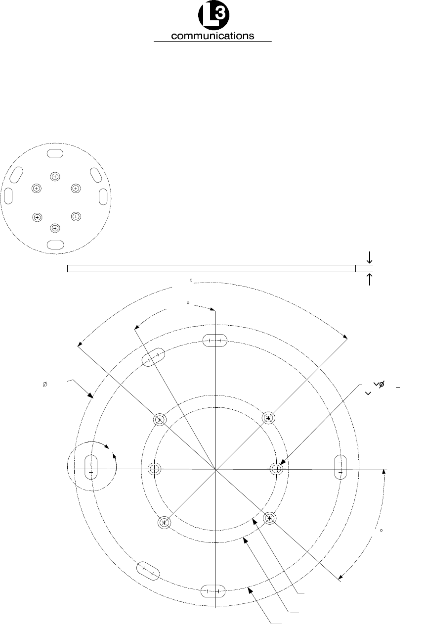
2.1. Mounting Plate & Dimensions
Figure 2--3 shows the AIS AtoN mounting plate, dimensions and mounting holes.
2X30
4X45
4.252
4.920
7.875
9.250
4X90
.250
P/N:115M0743--00
90 /0.260THRU
6X .496+.005
B
Figure 2--3. AIS AtoN Mounting Plate
Dimensions and Mounting Hole Pattern
Marine Systems
Aviation Recorders
Page 2--3
Rev. 9165M0829--00
October 17/08
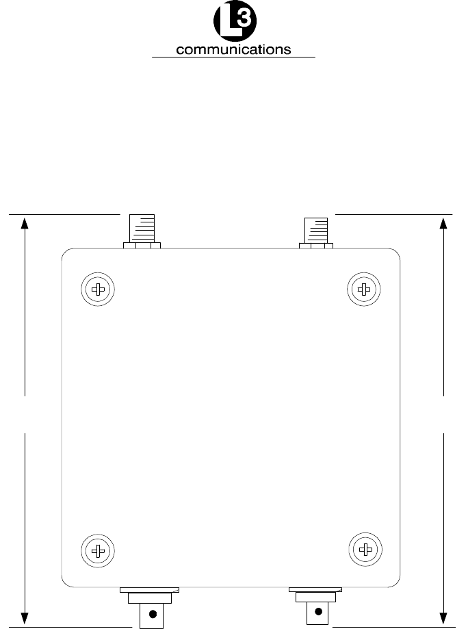
2.2. AIS AtoN Outlines and Dimensions
The basic dimensions of the AIS AtoN are illustrated in Figure 2--4, Figure 2--5,
Figure 2--6, and Figure 2--7.
[165]
6.5
[180]
7.1
Figure 2--4. AtoN Dimensions Including the Connectors
Marine Systems
Aviation Recorders
Page 2--4
165M0829--00Rev. 9
October 17/08
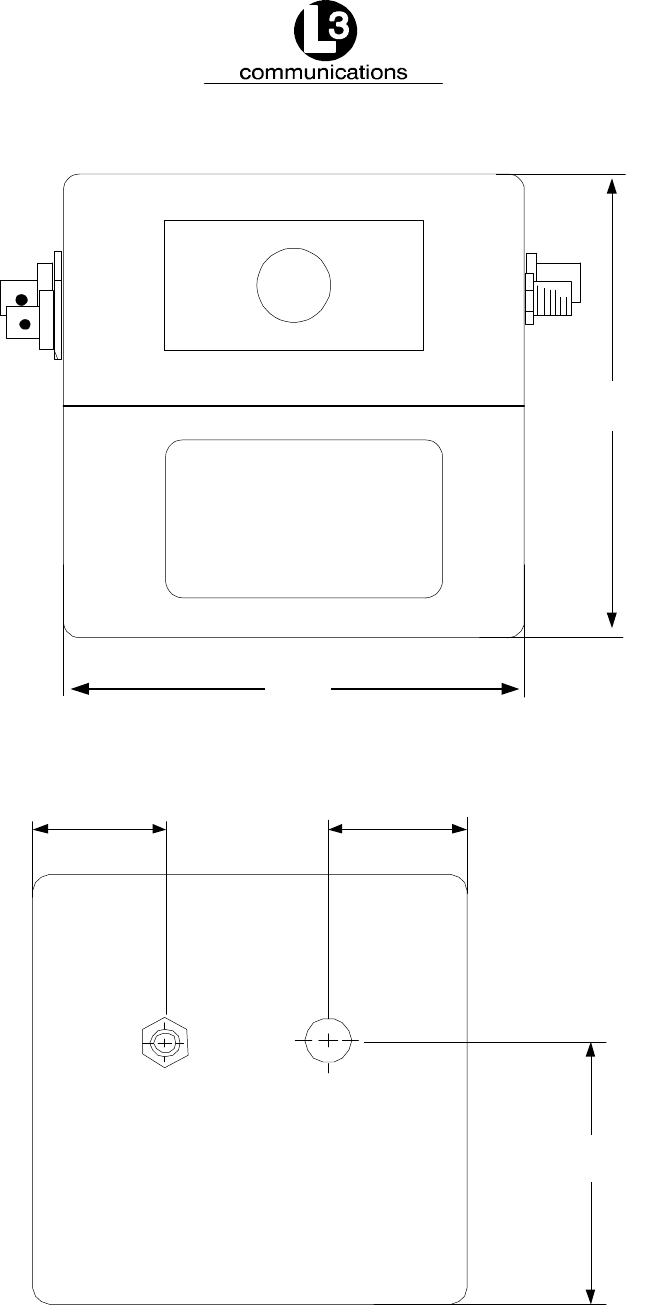
[134]
5.28
Height
[129]
5.1
Width
Figure 2--5. AIS AtoN Dimensions Without Connectors
[42]
1.64
[42]
1.64
[87]
2x3.44
Figure 2--6. AIS AtoN Connector Placements
Marine Systems
Aviation Recorders
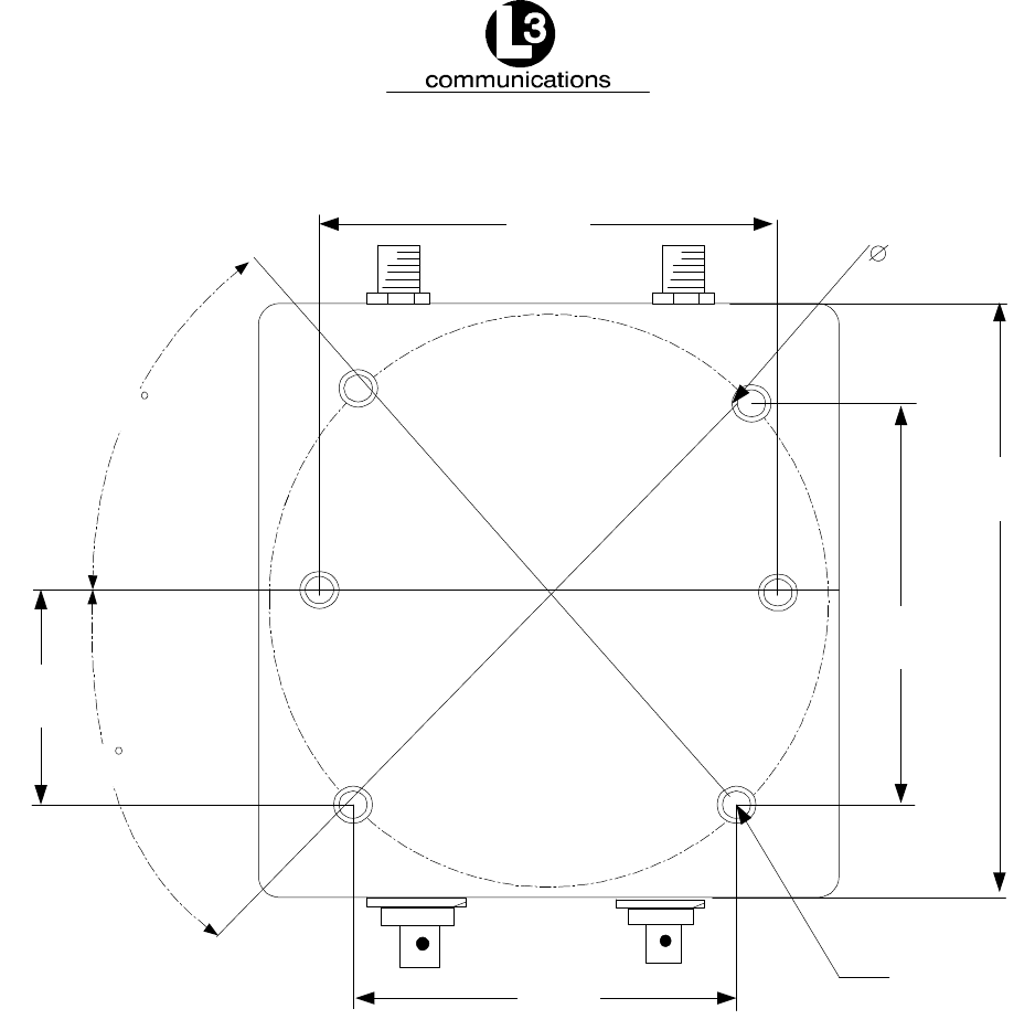
Page 2--5
Rev. 9165M0829--00
October 17/08
[129]
5.1
45
[88]
2X3.48
[44]
2X1.74
[88]
2X3.48
[108]
4.25 [125]
4.9
6X M6X1
X.35[9]
Free Running
Helicoil
45
Figure 2--7. AIS AtoN Outline & Dimensions
Marine Systems
Aviation Recorders
Page 2--6
165M0829--00Rev. 9
October 17/08
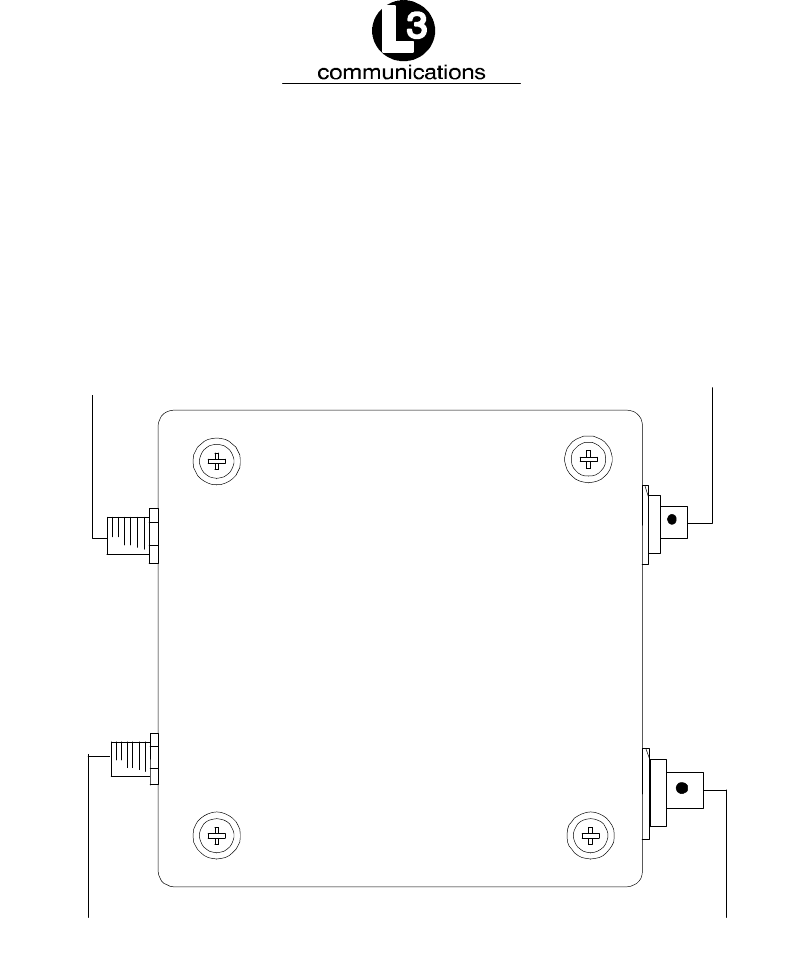
2.3. AIS AtoN Connections
Figure 2--8 illustrates the connectors on the AIS AtoN. The standard AtoN is de-
livered as a stand--alone unit without cables or antennas. The cables and antennas
must be purchased separately.
VHF
Antenna Port
(Type N RF Connector)
Sensor Data
Connection
GPS
TNC Connector
Power
Connection
Figure 2--8. AIS AtoN Connections

Marine Systems
Aviation Recorders
Page 2--7
Rev. 9165M0829--00
October 17/08
2.4. Power Connection Pinout
The Power Connectors are manufactured by Amphenol, and the pinout for the unit
connection is illustrated in Figure 2--9. The part number for the Power Connector on
the AIS AtoN unit is MILC--26482 Series 2, MS3474W12--3S. The part number for
the Power Cable Connector is MS3476W12--3P.
B
AC
Figure 2--9. Power Connection Pin Out
2.5. GPS Connection Pinout
As shown in Figure 2--10, the GPS connector on the AIS AtoN unit is a female TNC,
Amphenol 31--6111. The connector on the cable is an appropriate male TNC that
can withstand the marine environment. A sample connector is Amphenol 31--2373,
which can be used with cable numbers: RG--142 and RG--223.
Figure 2--10. GPS Connection Pinout

Marine Systems
Aviation Recorders
Page 2--8
165M0829--00Rev. 9
October 17/08
2.6. Sensor Data Connection Pinout
The Sensor Connectors are manufactured by Amphenol, and the pinout for the unit
connection is illustrated in Figure 2--11. The Sensor Data Connector on the AIS AtoN
unit is part number MS3474W14--19S. The cable is part number MS3476W41--19P.
This is an RS--232 setup with an IEC/serial port connecting to a DB9 cable.
GN
PIN
P
V
U
CONNECT
RSVD
RSVD
R
L
K
G
GND
RSVD
RSVD
RSVD
T
S
A
B
I E C --- T X
I E C --- R X
SYNC+
S Y N C ---
B
N
P
C
A
M
L
J
U
EST
F
G
H
DR K
V
D
Figure 2--11. Sensor Data Connection Pin Out

Marine Systems
Aviation Recorders
Page 3--1
Rev. 9165M0829--00
October 17/08
AIS AtoN Installation
NOTE: This device complies with Part 15 of the FCC rules. Operation is
subject to the following two conditions: (1) This device may not
cause harmful interference, and (2) this device must accept any
interference received, including interference that may cause un-
desired operation. Modifications not expressly approved by the man-
ufacturer could void the user’s authority to operate the equipment
under FCC rules.
3.1. Install the Power Cable
To begin installation, select a Power Cable, according to the following specifications.
FThe Power Cable must have a minimum wire size of 16AWG (1.3
mm/0.0508 inch)
FThe Power Cable voltage range must be 12--16VDC (nominal +12VDC).
3.2. Install the VHF Antenna
Installation of a VHF antenna is as important to reliable communications as the
transceiver itself. Figure 3--1 illustrates a typical VHF antenna setup.
N Connector
RG213RG214
Coaxial Cable
30 Meters
100 Feet
VHF Antenna
159 Mhz Center Frequency
<2.0 VSWR
6db Relative Gain
50 ohm
GPS
Connector
VHF
Connector
Figure 3--1. VHF Antenna Setup
Purchase a VHF marine band antenna from an established source and follow all of
the manufacturer’s instructions with particular attention to the cable routing and
connector installation. When installing the VHF antenna, follow the cautions below.
FPlace the antennas as high as practical on the buoy and separate them as
much as possible.

Marine Systems
Aviation Recorders
Page 3--2
165M0829--00Rev. 9
October 17/08
FPlace the antenna in an elevated position with a minimum of 2 meters of
clearance from all conductive material.
FInstall the antenna away from large, vertical obstructions.
FEnsure that the antenna has a 360°line of sight to the horizon.
To install the VHF antenna, perform the following:
(1) Position the antenna mounting bracket on a rigid and structurally sound surface
and install the antenna.
(2) Run the coaxial cable from the antenna to the AIS AtoN location.
(3) Trim the cable, leaving a few inches of slack at the AIS AtoN.
(4) Attach the connectors to the end of the coaxial cable. Solder the connection.
(5) To make sure that the cable is not shorted, check it with an ohm meter.
(6) Connect the cables to the AIS AtoN.
3.3. Install the GPS Antenna
Since the synchronization of internal transmission of the AIS AtoN relies on the
accuracy of the time signal obtained from the GPS system, the correct installation of
this antenna is crucial. To enhance good transmission, purchase a high quality GPS
antenna from an established source and follow all of the manufacturer’s instructions,
paying particular attention to the cable routing and connector installation. Figure 3--2
illustrates a typical GPS antenna setup.
TNC Male
Connector
GPS
Connector
VHF
Connector
9 Meters
30 Feet
RG213RG214
Coaxial Cable
GPS Antenna
5VDC
<3.0 VSWR
30dbl Total Gain
50 ohm
Figure 3--2. GPS Antenna Setup

Marine Systems
Aviation Recorders
Page 3--3
Rev. 9165M0829--00
October 17/08
When installing the GPS antenna, consider the following.
FBe sure no obstructions are between the antenna and the sky.
FSince GPS signals can be affected negatively by VHF transmissions, try to
position the GPS antenna at least 3 meters from the VHF antenna.
FPosition the antenna as high as possible to prevent ice or spray from neg-
atively affecting signal reception.
To install the GPS antenna, perform the following:
(1) Position the antenna mounting bracket and/or antenna mast on a rigid, structur-
ally sound surface.
NOTE: To reduce signal attenuation, use only high quality RG213/RG214
coaxial cable and keep the cable length as short as possible.
(2) Run the coaxial cable from the antenna to the transponder location through an
existing throughhull.
(3) Trim the cable, leaving a few inches of slack at the AIS AtoN.
(4) To make sure that the cable is not shorted, check it with an ohm meter.
(5) Attach the connectors to the end of the coaxial cable. Solder the connection.
(6) Connect the cable to the AIS AtoN, and solder the connection.

Marine Systems
Aviation Recorders
Page 3--4
165M0829--00Rev. 9
October 17/08
THIS PAGE IS INTENTIONALLY LEFT BLANK.
Marine Systems
Aviation Recorders
Page 4--1
Rev. 9165M0829--00
October 17/08
AIS AtoN Configuration
The transmit functions of the AIS AtoN must be configured prior to installation.
Basically, the configuration specifies which messages are transmitted, how often
they are sent, and the specific VHF data link (VDL) slot used to transmit them.
NOTE: All message assignments and intervals must be defined and
approved by the appropriate competent authority, such as the
local port authority where the AIS AtoN is installed.
4.1. Set Up Hyper Terminal
Configuration is accomplished with a personal computer (PC), running any simple
terminal emulator for the computer interface. This manual uses a Windows “Hyper-
Terminal” screen as the computer interface tool. To begin configuration, connect a
power cable into the Power Connector and the other end into a power source.
Connect the AtoN External Configuration Cable (L--3 P/N 024M0841--00) to the
computer’s serial port and the Sensor (serial) Interface Connector of the AIS AtoN.
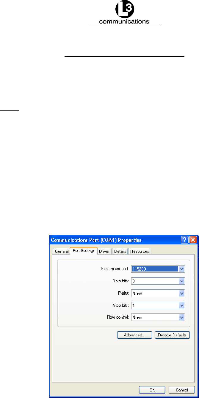
Turn on the unit. In the Microsoft Windows “Properties” window, set the “Port Set-
tings” at “115200 Baud,” “8 Data Bits,” “No Parity,” “1 Stop Bit,” and “No Flow Con-
trol,” as shown in Figure 4--1.
Figure 4--1. Set Up the Communications Port Properties
Marine Systems
Aviation Recorders
Page 4--2
165M0829--00Rev. 9
October 17/08
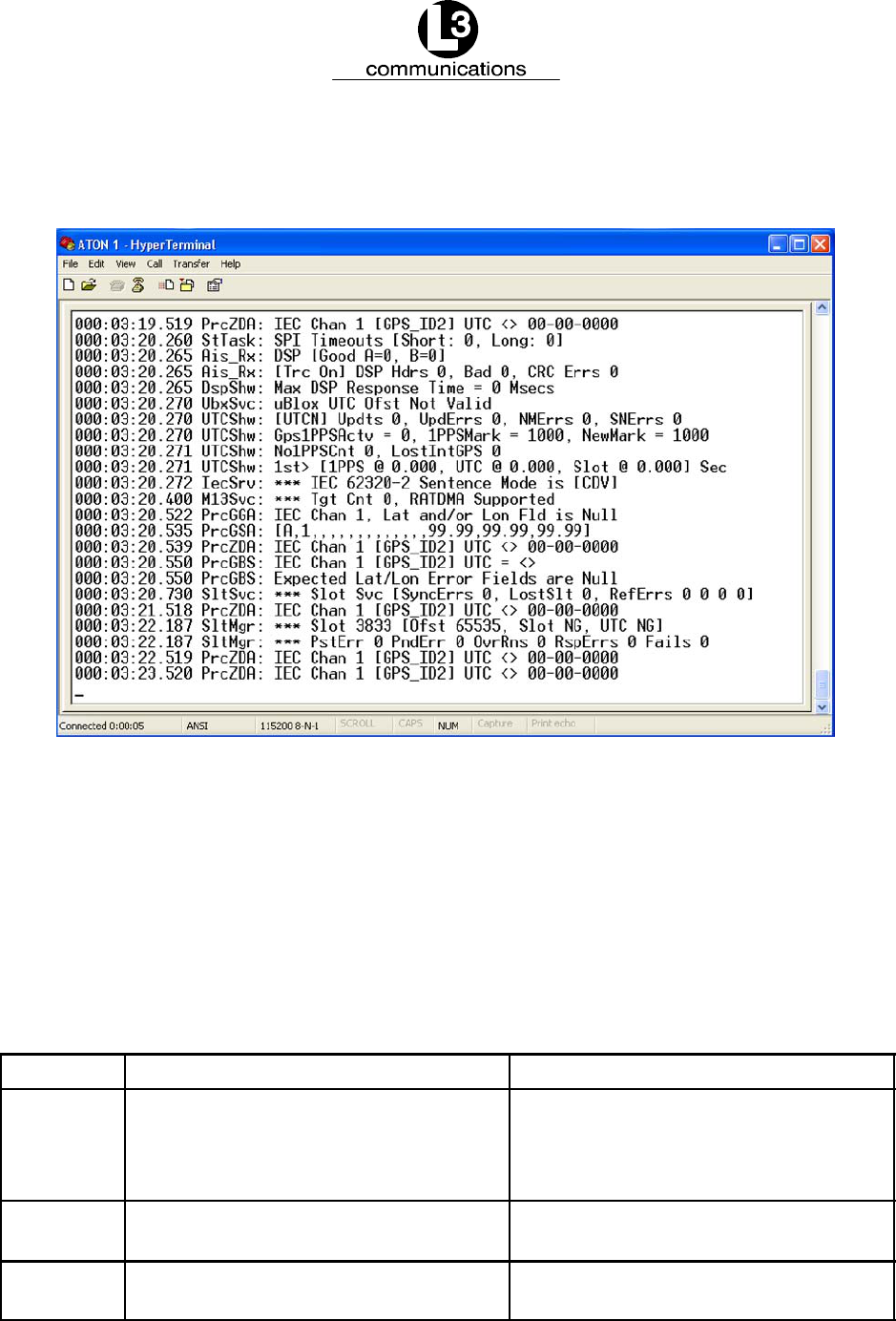
Trace output messages from the ARM processor in the AIS AtoN unit should appear
in the “HyperTerminal” window, as shown in Figure 4--2.
Figure 4--2. Display Typical Startup Screen with Trace Messages
4.2. Navigate the HyperTerminal
The HyperTerminal screen displays trace messages or the “System Configuration
Menu,” which is described in the next section. Table 4--1 describes basic keys that
are used to navigate these screens. Additional keys that are used in each individual
screen are explained throughout this manual.
Table 4--1. HyperTerminal Key Descriptions
Key Trace Message Screen Features System Configuration Menu Features
ESC Takes the screen out of sleep mode
and begins to display trace messages
again
Takes the user back to the previous
screen; Displays a menu exit message
in the main “System Configuration”
menu
Space Bar Stops and restarts the display of trace
messages
Enables and disables some of the fea-
tures by toggling them on or off
COpens the “System Configuration”
menu
Not Applicable
Marine Systems
Aviation Recorders
Page 4--3
Rev. 9165M0829--00
October 17/08
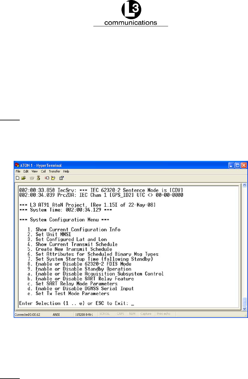
4.3. System Configuration Menu
An intuitive set of screens set up under the “System Configuration Menu” provides
users with the options needed to configure the AIS AtoN for maintenance--free use.
To access this menu, press “C” in the “HyperTerminal” screen while it is transmitting
trace messages. The window shown in Figure 4--3 appears.
NOTE: If trace messages are not displayed, press “ESC,” and a “Hit
Any Key to Reboot” message appears. Press any key, so the
system reboots. Press “C” to open the “System Configuration
Menu.”
Figure 4--3. Display the System Configuration Menu
To configure a specific feature, type in the menu number or letter associated with it,
and press “Enter.” This opens self--explanatory options at the bottom of the screen.
NOTE: When these menus are used, normal AIS AtoN operation is ter-
minated. Whether or not changes are made to the configuration
when the menus are exited, the system automatically prompts
the user to reboot with the “Hit Any Key to Continue...” mes-
sage. Press any key, and the“Enter Selection (1 .. e) or ESC to
Exit” message appears. Press “ESC,” and then type in a number
or letter to select a menu option.
Marine Systems
Aviation Recorders
Page 4--4
165M0829--00Rev. 9
October 17/08
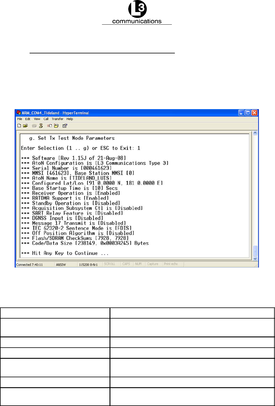
4.3.1. Display the Current Transmit Configuration
When “1” is entered in the “System Configuration Menu,” the “Current Configuration
Information” screen appears with a summary of the AIS AtoN’s existing setup, as
show in Figure 4--4. Press any key to return to the main “System Configuration
Menu.” Table 4--2 describes the parameters in this screen, which are some of the
basic features in the AIS AtoN.
Figure 4--4. View the Current Configuration Information Screen
Table 4--2. Current Configuration Field Descriptions
Field Description
Software Displays the revision of the software currently running
on the AtoN
AtoN Configuration Describes the type of AIS AtoN unit
Serial Number Displays the serial number of the AIS AtoN unit
MMSI Shows the MMSI of the AIS AtoN, which is set at “0” as
a factory default
AtoN Name Displays the name of the AIS AtoN I.D. string
Configured Lat/Lon Indicates the charted location (latitude and longitude)
of the AtoN, as it is shown on international charts

Marine Systems
Aviation Recorders
Page 4--5
Rev. 9165M0829--00
October 17/08
Field Description
Base Startup Time Defines the wake up time needed to prepare for a
transmission; When an AtoN wakes up from Standby
mode, it must acquire UTC time; Normally, this process
takes 10 seconds or less (default setting); In areas
where GPS reception is poor, or Standby times are
longer than 10 minutes, this setting can be changed to
wake up sooner.
Receiver Operation Indicates whether or not the AIS AtoN has its receivers
turned on
RATDMA Support Indicates whether or not RATDMA transmissions are
enabled
Standby Operation Indicates whether Standby (Sleep) mode is enabled to
conserve battery life
Acquisition Subsystem Control Should be enabled when a daugtherboard is installed
in the AIS AtoN; Manages the interface between the
motherboard and daugtherboard; Enables extended
MPR operations
SART Relay Feature Shows whether or not the AIS AtoN is set to receive a
Search and Rescue Transponder (SART) message,
which the AIS AtoN repeats for a pre--defined amount
of time; Overrides power saving settings; Factory test
only; Leave disabled
DGNSS Input Indicates whether data is accepted from an external
DGNSS receiver; Disables IEC port if enabled; Factory
test only; Leave disabled
Message 17 Transmit Shows whether Message 17 corrections are transmit-
ted; Factory test only; Leave disabled
IEC 62320--2 Sentence Mode Displays the 62320--2 mode, which is either “CDV” or
“FDIS”
Off--Position Algorithm Shows whether an optional algorithm is used to calcu-
late off--position; Factory test only; Leave disabled
Flash SDRAM CheckSums Duplicate numbers indicate that the software image is
loaded properly
Code Data Size Indicates the size of the code file
Marine Systems
Aviation Recorders
Page 4--6
165M0829--00Rev. 9
October 17/08
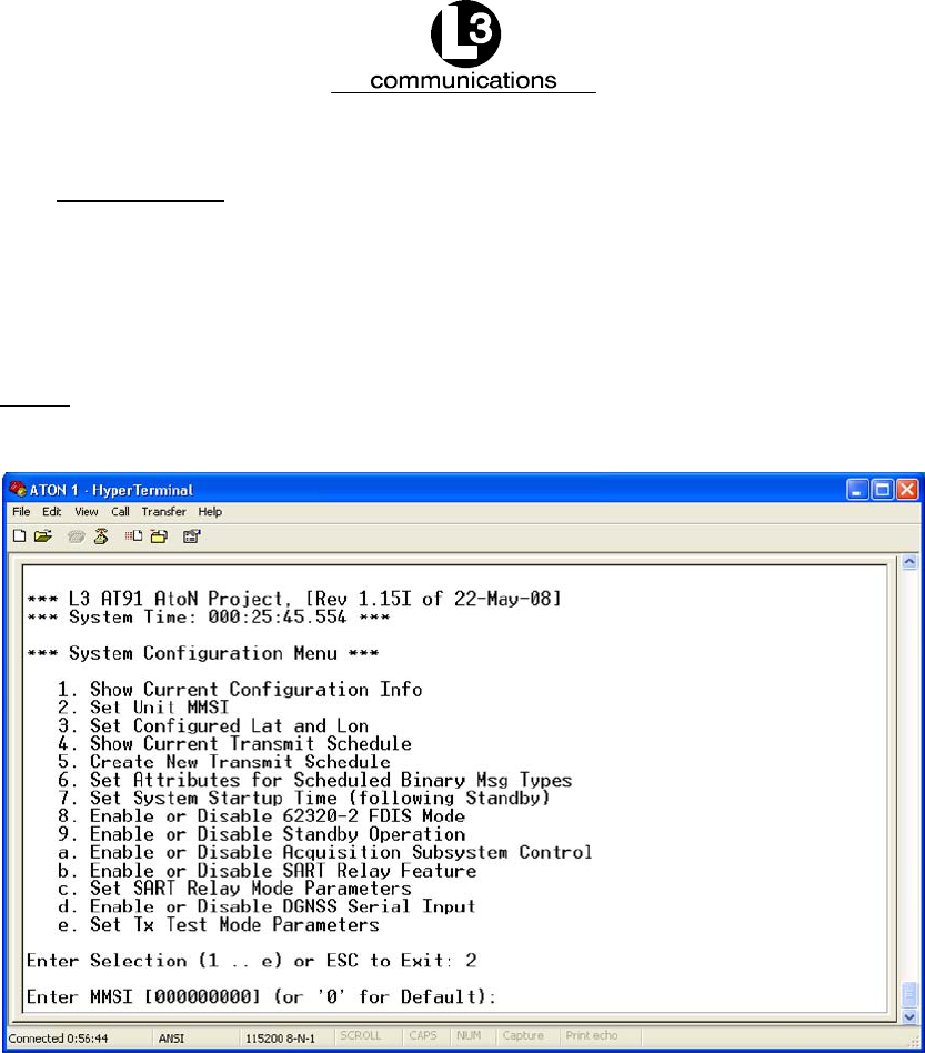
4.3.2. Set the MMSI
To set the MMSI, enter “2” in the main “System Configuration Menu,” and the option
to change the MMSI appears, as shown in Figure 4--5. If needed, change the MMSI,
and press “Enter.” When the “Hit Any Key to Continue...” message appears, press
any key to return to the main “System Configuration Menu.”
NOTE: The MMSI is controlled by a competent authority and must be a
legitimate number. The factory default is “0.”
Figure 4--5. Change the MMSI Mode
Marine Systems
Aviation Recorders
Page 4--7
Rev. 9165M0829--00
October 17/08
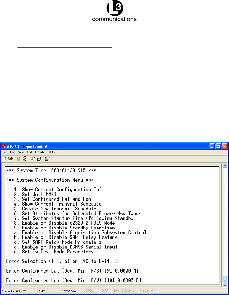
4.3.3. Set the Latitude and Longitude
The latitude/longitude feature tells the system where the AIS AtoN is supposed to be
located, according to international charts. The AIS AtoN compares the latitude and
longitude information with GPS data to determine whether or not the unit has drifted
from its charted position. When the unit is off--position, Message 21 indicates an
“off--position” status.
To set the latitude and longitude, enter “3” in the main “System Configuration Menu,”
and the “Latitude” option appears, as shown in Figure 4--6. Enter the “Degrees” and
“Minutes” and press “Enter.” When the “Longitude” option appears, type in the
“Degrees” and “Minutes” and press “Enter.” Press any key to return to the main
“System Configuration Menu.”
Figure 4--6. Set the Latitude and Longitude
Marine Systems
Aviation Recorders
Page 4--8
165M0829--00Rev. 9
October 17/08
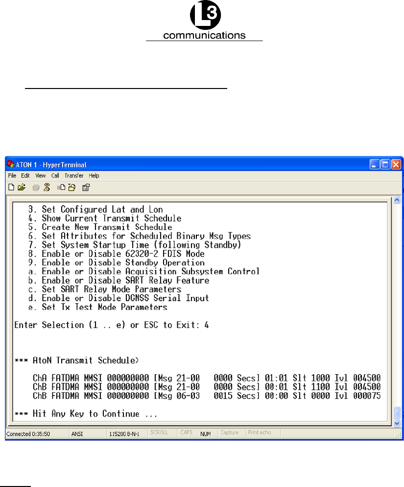
4.3.4. View the Current Transmit Schedule
To view the ”Current Transmit Schedule,” enter “4” in the main “System Configuration
Menu,” and the screen shown in Figure 4--7 displays a summary. Press any key to
return to the main “System Configuration Menu.”
Figure 4--7. View the Current Transmit Schedule
NOTE: This schedule is an example only.
Marine Systems
Aviation Recorders
Page 4--9
Rev. 9165M0829--00
October 17/08
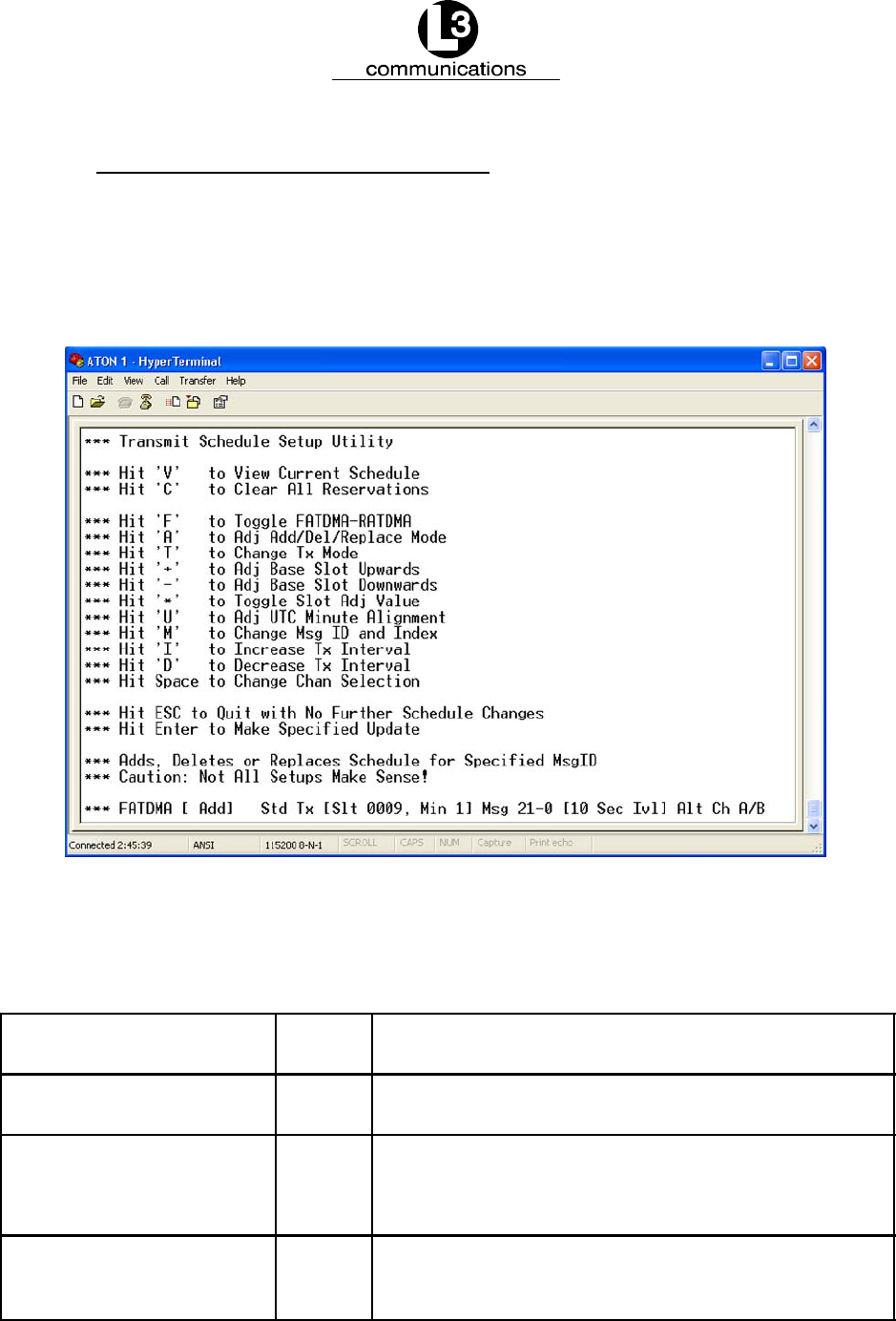
4.3.5. Add or Replace Transmit Schedules
To set the transmit data, enter “5” in the main “System Configuration Menu,” and the
screen in Figure 4--8 opens with the message “Adds or Replaces Schedule for
Specified MsgID.” Table 4--3 describes the configurable fields displayed in the last
line of the screen.
Figure 4--8. Change the Transmit Schedule
Table 4--3. Transmit Schedule Setup Utility Field Descriptions
Field Key
Stroke
Description
FATDMA / RATDMA FEnables the user to toggle between the FATDMA and
RATDMA formats
[Add]
[Rplc]
[Del]
ATells the unit that the user is either adding a new transmit
schedule or replacing or deleting the existing schedule
Tx TToggles between “Std” (Standard) and “Back2Back” forms
of transmission; Typically set to “Std,” but special test sce-
narios might require “Back to Back” transmissions

Marine Systems
Aviation Recorders
Page 4--10
165M0829--00Rev. 9
October 17/08
Field Key
Stroke
Description
[Slt 0009,Min1] “Shift”
“+”
Sets the slot on which to transmit the message; Press
“Shift” and “+” (plus sign) key to increase the value of the
“base” or “anchor” slot by increments of either 1 or 10, de-
pending upon how the adjustment is set with the “Shift” and
“*” keys
[Slt 0009,Min1] “--” Decreases the value of the “base” or “anchor” slot by incre-
ments of either 1 or 10, depending upon how the adjust-
ment is set with the “Shift” and “*” keys
[Slt 0009,Min1] “Shift” * Toggles the amount the base slot is adjusted between in-
crements of either 1 or 10, allowing for fine control over the
slot
[Slt 0009, Min 1] U Changes the Universal Coordinated Time (UTC) by incre-
ments of 1 minute, ranging from 0 to 9 minutes
Msg MCycles through the message types to select a message to
configure
[10 Sec Ivl] IIncreases the time between message transmissions by
cycling the slot adjustment to within a range of 2 seconds
and 30 minutes (decreases the transmission rate)
[10 Sec Ivl] DDecreases the time between message transmissions by
cycling the slot adjustment to within a range of 2 seconds
and 30 minutes (increases the transmission rate)
Ch A Only / Ch B Only
/ChA/B
Space
Bar
Selects the type of channel used to transmit the message
Action Key VDisplays a current view of the schedule
Action Key CClears all current reservations
After making a change and pressing the “ENTER” button, the “AtoN Transmit Sched-
ule” appears with the message “Hit Any Key to Continue...” Press any key, and the
“Transmit Schedule Setup Utility” screen reappears. Press “Esc” in the main “Trans-
mit Schedule Utility” screen to return to the main “System Configuration Menu.”
Marine Systems
Aviation Recorders
Page 4--11
Rev. 9165M0829--00
October 17/08
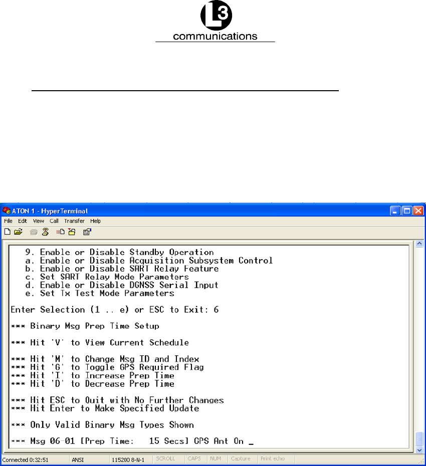
4.3.6. Set Preparation Time for Scheduled Binary Messages
This “Binary Message Prep Time” feature defines the preparation time needed to
acquire the information contained in the binary message payload, such as meteoro-
logical or hydrological records. To create scheduled binary messages, enter “6” in
the main “System Configuration Menu,” and the option shown in Figure 4--9 appears.
For information on binary messages, see a description in the “Introduction” section
of this manual.
Figure 4--9. Set the Preparation Time for Binary Messages
To select a message, press “M” to scroll through the available message types and
select one. Press “I” to increase the preparation time by 5 seconds each time the
key is hit. Press “D” to decrease preparation time by 5 seconds each time the key is
hit. Press “G” to toggle the GPS antenna on or off.
When the changes are complete, press “Enter,” and the “AtoN Transmit Schedule”
appears. Press “Esc,” and the “Binary Msg Prep Time Setup” reappears. Press “Esc”
again to return to the main “System Configuration Menu.”
Marine Systems
Aviation Recorders
Page 4--12
165M0829--00Rev. 9
October 17/08
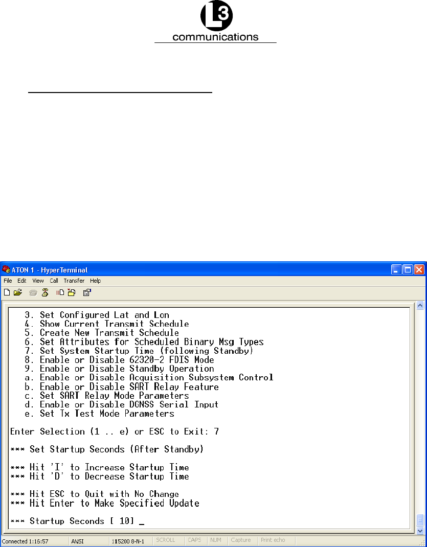
4.3.7. Set Post--Standby Startup Time
In order to save power, the AIS AtoN goes into standby mode when it does not have
an imminent event to process. The “System Startup Time” defines when the mother-
board needs to wake up from standby mode to prepare for a transmission.
To set the start--up time following standby of the unit, enter “7” in the main “System
Configuration Menu,” and Figure 4--10 appears. Press “I” to increase the value by 1
second each time the key is hit or “D” to decrease the time by 1 second each time it
is hit. The range of startup times is between 10 and 30 seconds. Press “Enter” to
accept the changes, and the “Press Any Key to Continue...” message appears. Hit
any key to return to the main “System Configuration Menu.”
Figure 4--10. Set the Post--Startup Time
Marine Systems
Aviation Recorders
Page 4--13
Rev. 9165M0829--00
October 17/08
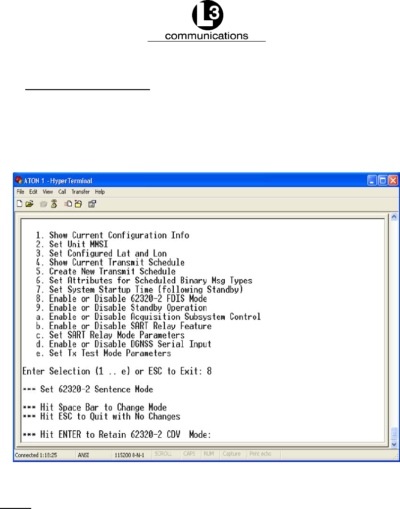
4.3.8. Set the 62320--2 Mode
The “62320--2 Mode” can be either “CDV” or “FDIS.” Enter “8” in the main “System
Configuration Menu,” and Figure 4--11 appears. Press the “Space Bar” to toggle
between the modes. Hit the “Enter” key, and the “Hit Any Key to Continue...” mes-
sage appears. Press any key to return to the main “System Configuration Menu.”
Figure 4--11. Set the 62320--2 FDIS Mode
NOTE: The document that defines the technical specification for AtoN
performance is named IEC 62320--2. There are two versions that
cause slight changes in AtoN behavior. Contact the Competent
Authority to determine the version with which the AtoN must
comply.
Marine Systems
Aviation Recorders
Page 4--14
165M0829--00Rev. 9
October 17/08
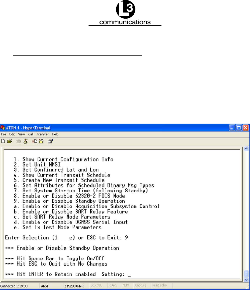
4.3.9. Toggle the Standby Option Off or On
In order to maximize power efficiency, the “Standby Operation” should remain en-
abled. To turn the standby option on or off, enter “9” in the main “System Configura-
tion Menu,” and the screen shown in Figure 4--12 opens. Press the “Space Bar” to
toggle Standby mode “on” or “off.” Hit the “Enter” key, and the “Hit Any Key to
Continue...” message appears. Press any key to return to the main “System Config-
uration Menu.”
Figure 4--12. Turn Standby Operation On or Off
Marine Systems
Aviation Recorders
Page 4--15
Rev. 9165M0829--00
October 17/08
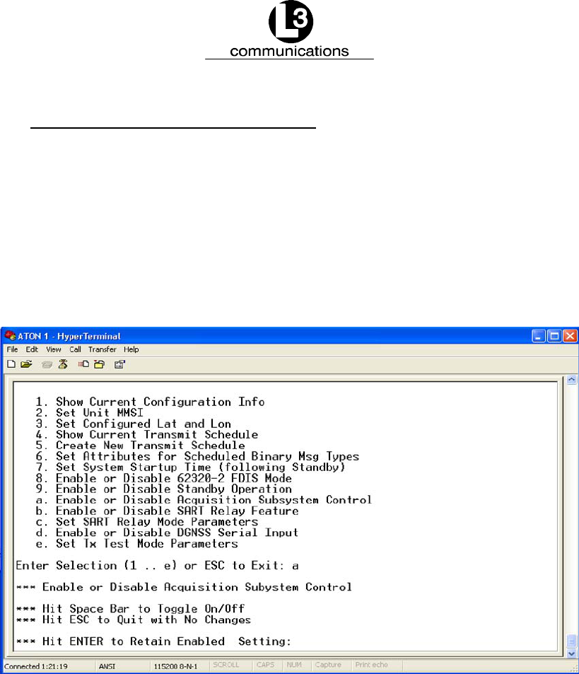
4.3.10. Control the Acquisition Subsystem
When a daugtherboard is installed in the AIS AtoN, the “Acquisition Subsystem
Control” manages the interface between the motherboard and daugtherboard. This
feature also enables extended MPR operations, which provide payloads for some
optional messages. To control the acquisition subsystem, enter “a” in the main
“System Configuration Menu,” and the screen shown in Figure 4--13 open. Press the
“Space Bar” to enable or disable the acquisition mode. When the “Hit Any Key to
Continue...” message appears, press any key to return to the main “System Config-
uration Menu.”
Figure 4--13. Control the Acquisition Subsystem
Marine Systems
Aviation Recorders
Page 4--16
165M0829--00Rev. 9
October 17/08
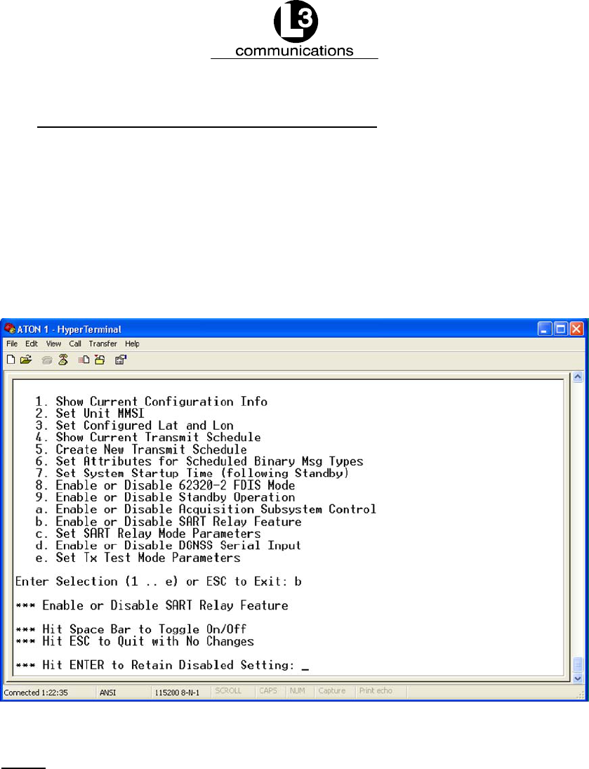
4.3.11. Enable or Disable the SART Relay Feature
When the “SART Relay Feature” is enabled, the AIS AtoN receives a SART mes-
sage and repeats the message at an established interval for a pre--defined amount
of time. This feature overrides power saving settings.
To enable or disable SART transmissions, enter “b” in the main “System Configura-
tion Menu,” and the screen shown in Figure 4--14 appears. Press the “Space Bar” to
enable or disable the SART Relay feature. When the “Hit Any Key to Continue...”
message appears, press any key to return to the main “System Configuration Menu.”
Figure 4--14. Enable or Disable the SART Relay Feature
NOTE: This is a factory test that should remain disabled.
Marine Systems
Aviation Recorders
Page 4--17
Rev. 9165M0829--00
October 17/08
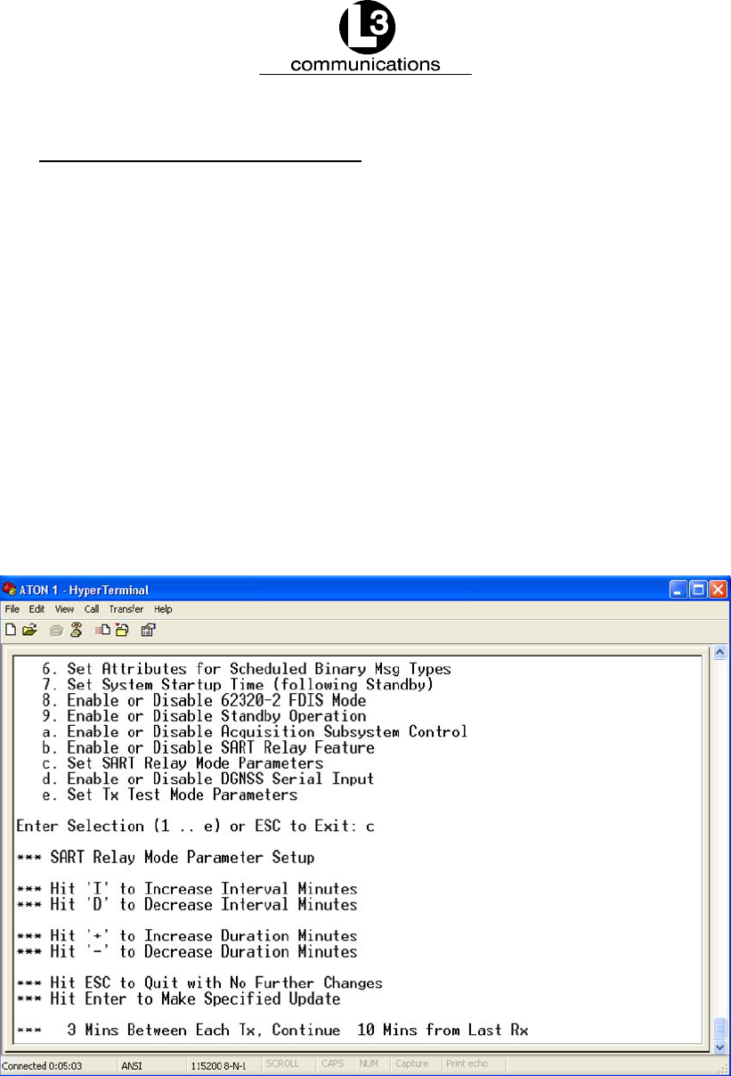
4.3.12. Set the SART Relay Parameters
The “SART Relay Mode” requires that the “Interval” and “Duration” parameters be
defined. The “Interval” parameter determines how often the message is retransmit-
ted, and the “Duration” parameter sets how long the unit continues to repeat the
message. To establish the SART parameters, enter “c” in the main “System Config-
uration Menu,” and Figure 4--15 appears.
Press “I” to increase the interval of minutes between each transmission by 1 minute
each time the key is hit, and decrease it by 1 minute each time “D” is pressed. The
interval can be set between 1 to 10 minutes.
To set how long the unit continues to repeat the message, press “Shift” and “+” to
increase the “Duration” by 1 minute and “--” to decrease the amount by 1 minute.
This range can be set from 3 to 600 minutes. Hit “Enter,” and the “Hit Any Key to
Continue...” message appears. Press any key to return to the main “System Config-
uration Menu.”
Figure 4--15. Set SART Relay Mode Parameters
Marine Systems
Aviation Recorders
Page 4--18
165M0829--00Rev. 9
October 17/08
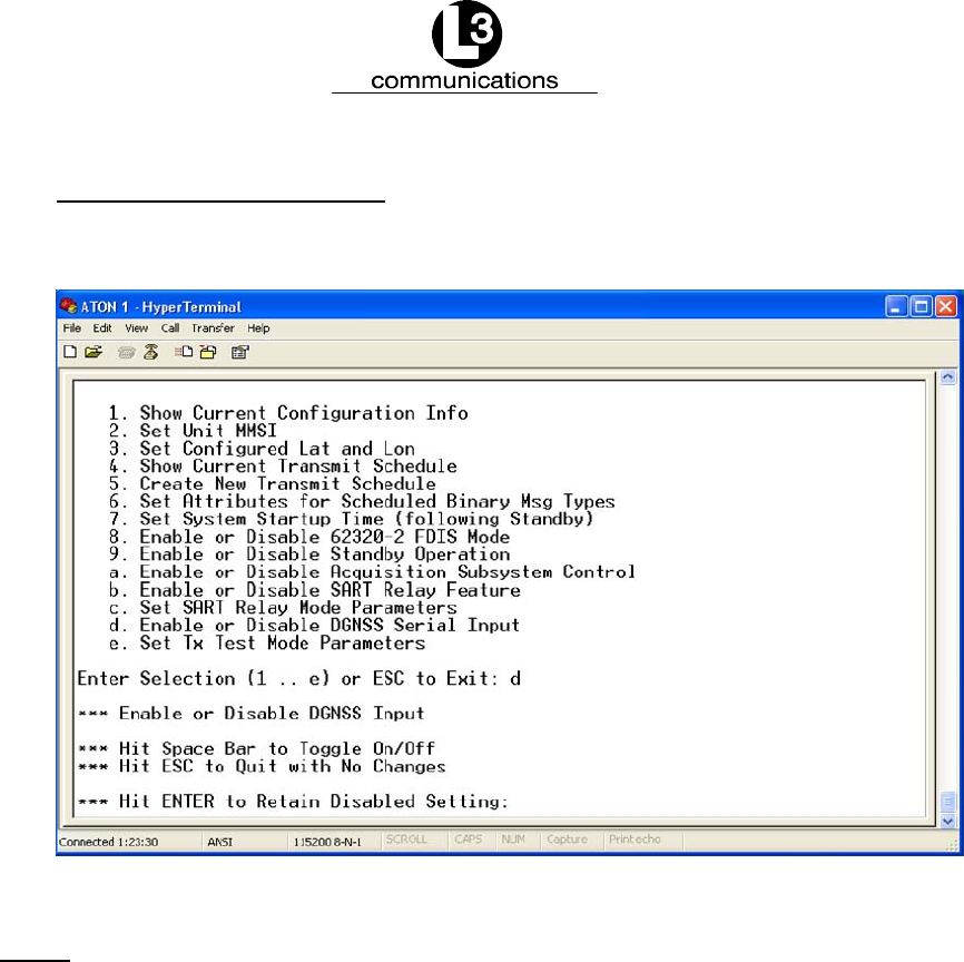
4.3.13. Enable or Disable DGNSS
This is a feature used to test the AIS AtoN.
Figure 4--16. Enable or Disable the DGNSS Serial Input
NOTE: This is a factory test that should remain disabled.
Marine Systems
Aviation Recorders
Page 4--19
Rev. 9165M0829--00
October 17/08
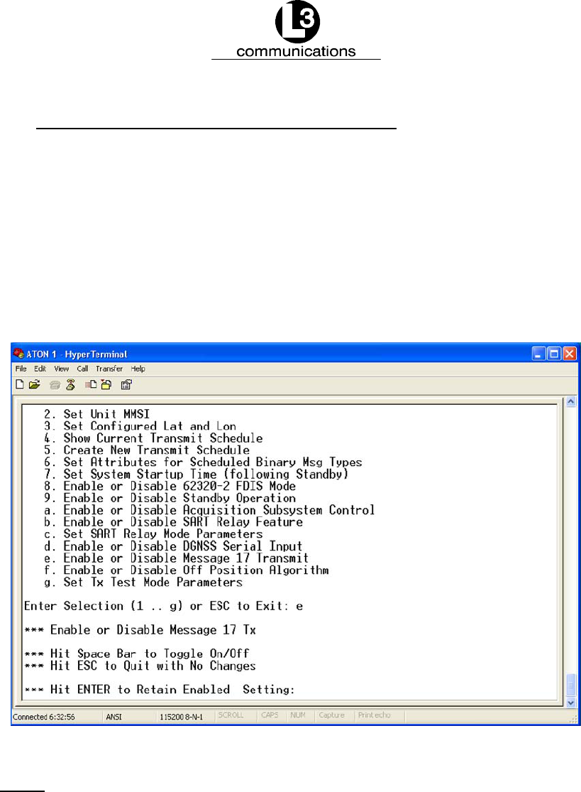
4.3.14. Enable or Disable Message 17 Transmission
This is a feature used to test the AIS AtoN. Message 17 is used to differentially
correct GNSS positions to DGNSS positions. It should be transmitted by a base
station, which is connected to a DGNSS reference source, and configured to provide
DGNSS data to receiving stations.
To enable or disable the transmission of Message 17, enter “e” in the main “System
Configuration Menu.” As shown in Figure 4--17, press the “Space Bar” to enable or
disable input. Hit “Enter,” and the “Hit Any Key to Continue...” message appears.
Press any key to return to the main “System Configuration Menu.”
Figure 4--17. Enable or Disable Message 17 Transmission
NOTE: This is a factory test that should remain disabled.
Marine Systems
Aviation Recorders
Page 4--20
165M0829--00Rev. 9
October 17/08
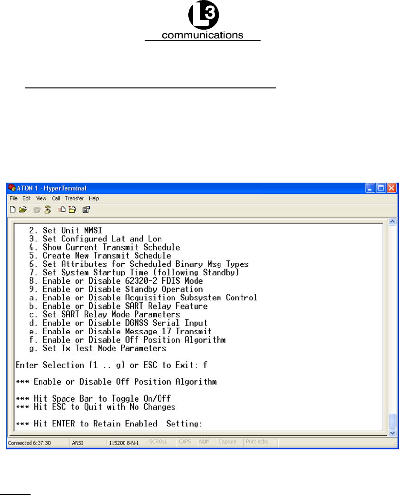
4.3.15. Enable or Disable the Off--Position Algorithm
This feature is an extended algorithm that controls the AIS AtoN off--position flag in
Message 21. To enable or disable the extended algorithm, enter “f” in the main
“System Configuration Menu.” As shown in Figure 4--18, press the “Space Bar” to
enable or disable input. Hit “Enter,” and the “Hit Any Key to Continue...” message
appears. Press any key to return to the main “System Configuration Menu.”
Figure 4--18. Enable or Disable AIS AtoN Position Report
NOTE: This is a factory test that should remain disabled.
Marine Systems
Aviation Recorders
Page 4--21
Rev. 9165M0829--00
October 17/08
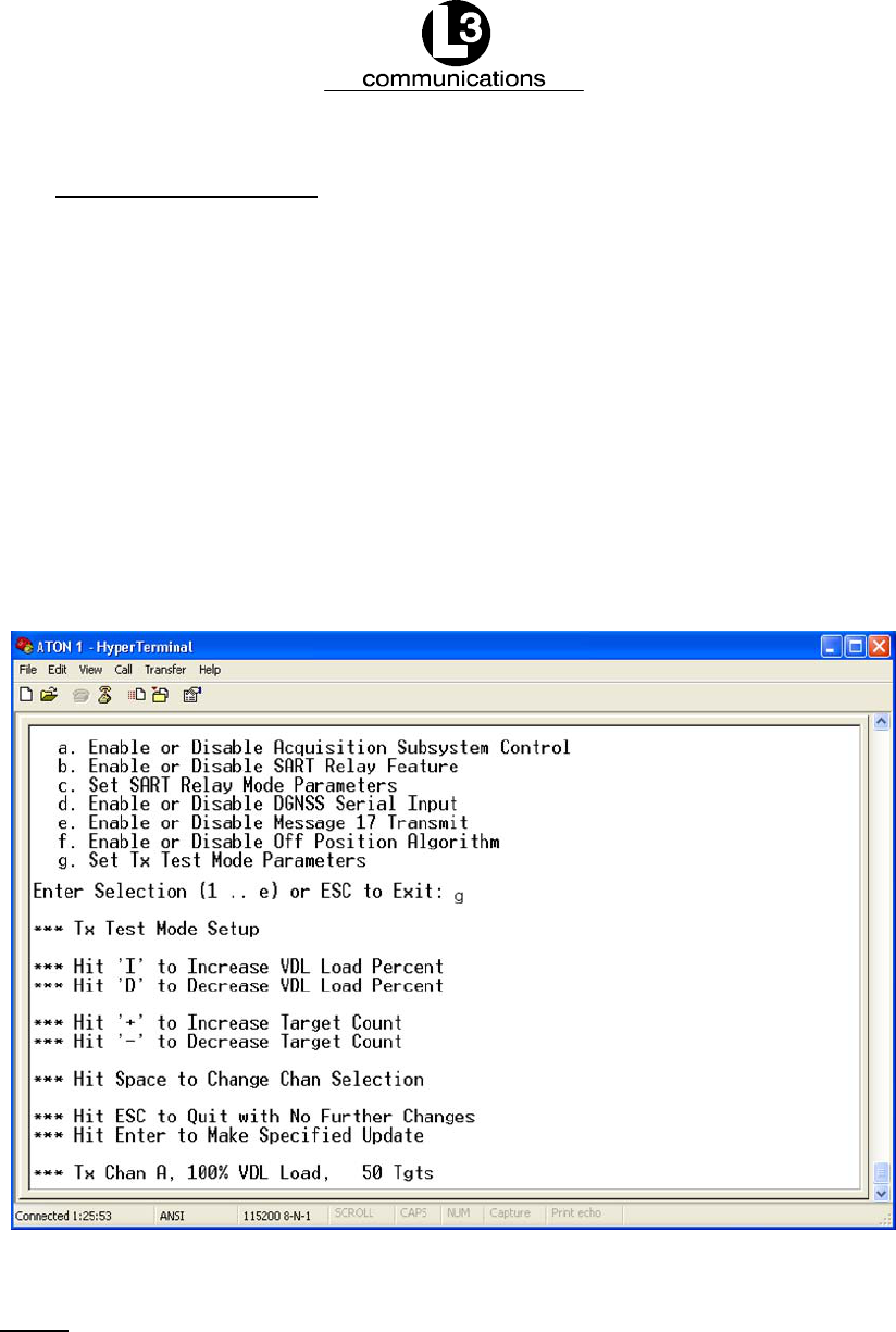
4.3.16. Set the Tx Test Mode
This is a feature used to test the AIS AtoN by simulating a given percentage of use
of the VDL and a number of unique targets. To set the Tx test mode parameters,
enter “g” in the main “System Configuration Menu,” and the screen shown in
Figure 4--19 displays the options.
Press “I” to increase the “VDL Load” by 10 percent each time the key is hit and “D”
to decrease it by 10 percent. Press “Shift” and “+” to increase the “Target Count” and
“--” to decrease it.
Hit the “Space Bar” to toggle through the available channels and select one.
Hit the “Enter” key and the “Hit Any Key to Continue...” message appears. Press any
key to return to the main “System Configuration Menu.”
Figure 4--19. Set the Tx Test Mode Parameters
NOTE: This is a factory test that should remain disabled.

Marine Systems
Aviation Recorders
Page 4--22
165M0829--00Rev. 9
October 17/08
4.4. Reset the AIS AtoN From the ARM HyperTerminal Console
When the AIS AtoN is running and trace messages are displayed on the ARM
HyperTerminal console, the unit can be reset at any time by holding the “Ctrl” key
and typing “C” twice quickly. This eliminates the need to cycle the power and restart
the AIS AtoN. Trace messages should scroll through the HyperTerminal screen.
4.5. Troubleshoot the HyperTerminal
Since the HyperTerminal provides a direct portal to the AtoN CPU, in rare circum-
stances it may stop displaying trace messages. Use the following instructions to
display trace messages.
(1) Press “ESC,” and a “Hit Any Key to Reboot” message appears. Press any key,
so the system reboots.
(2) If messages are not displayed once the unit is reset or a key is pressed, close
the HyperTerminal screen and re--open it.
(3) If trace messages are not displayed after shutting down and re--opening the
HyperTerminal screen, do the following.
i. Shut down the computer and the turn off the AIS AtoN.
ii. Unplug all connections to the unit.
iii. Plug the connectors back into the unit, restart the AIS AtoN, and re--open
the HyperTerminal screen.
4.6. Resolve Failure Mode
The AtoN handles antenna failures, based upon whether the problem occurs during
a transmission or reception of a message.
4.6.1. For a Transmission Fault and Disabled Antenna
A disabled antenna is detected by the AIS AtoN DSP as an antenna with a high
VSWR during the transmission of a message. If a high VSWR is detected, the DSP
stops transmission before a message completes transmission.
4.6.2. For Reception Fault
The AIS AtoN uses a frequency synthesizer that incorporates a digital Phase Locked
Loop (PLL). If both receivers are locked, a “Lock Detect” status signal is sent, indi-
cating that the receivers are functioning. In Type 3 AtoNs, if either or both receivers
fail to lock then the “Lock Detect” status indicates a fault, and RATDMA transmis-
sions are stopped on the receiver that is not locked.

Marine Systems
Aviation Recorders
Page A--1
Rev. 9165M0829--00
October 17/08
Additional Features
A.1. Type 1 AIS AtoN Station Alternatives
In addition to Message 21, the controller will compose optional output messages to the VDL, using
FATDMA, as described in Table 1.
Table 1. Summary of optional Type 1 AIS AtoN Station messages
Msg
ID
Message name Message description Application examples
6Binary addressed message Binary data for addressed
communication
Monitoring of AtoN lantern,
power supply, etc.
8Binary broadcast message Binary data for broadcast
communication
Meteorological and hydrologic-
al data
12 Addressed safety related mes-
sage
Safety related data for broad-
cast communication
Warn AtoN malfunctioning
14 Broadcast safety related mes-
sage
Safety related data for broad-
cast communication
Warn AtoN malfunctioning
A.2. Type 3 AIS AtoN Station -- Alternatives
The Type 3 AIS AtoN Station alternatives include all the Type 1 and Type 2 AIS AtoN Station
alternatives.
A.2.1. Additional Controller Capability
In addition to Message 21, the controller composes optional output messages to the VDL, as
described in Table 2.
Table 2. Summary of optional Type 3 AIS AtoN Station messages
Msg
ID
Message name Message description Application examples
6Binary addressed message Binary data for addressed
communication
Monitoring of AtoN equipment
8Binary broadcast message Binary data for broadcast
communication
Meteorological and hydrologic-
al data
12 Addressed safety related mes-
sage
Safety related data for broad-
cast communication
Warn AtoN malfunctioning
14 Broadcast safety related mes-
sage
Safety related data for broad-
cast communication
Warn AtoN malfunctioning

Marine Systems
Aviation Recorders
Page A--2
165M0829--00Rev. 9
October 17/08
THIS PAGE IS INTENTIONALLY LEFT BLANK.

Marine Systems
Aviation Recorders
Page B--1
Rev. 9165M0829--00
October 17/08
Firmware Update
In order to update AtoN firmware, the following is required.
FPower Cable: Refer to the “Mounting and Connections” section of this
manual for more details on the pinout.
FCommunications Cable: Refer to the “Mounting and Connections” section
of this manual for more details on the pinout.
FFirmware Update Package
B.1. Normal ARM Code Update (ARM Standalone Image Already
Installed)
If the unit has already been updated with a standalone binary ARM version, it can be
subsequently updated with a different version of ARM code, using a simple proced-
ure that does not require the unit to be opened. The following procedure describes
the normal method used to update software.
The unit should be powered up with the Communications/Sensor port connected to
the “HyperTerminal” at “115200 Baud.”
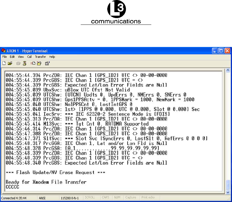
(1) While trace messages are displayed on the “HyperTerminal” console, hold the
“Ctrl” key and type “FF.” As shown in Figure B--1, the following message ap-
pears.
*** Flash Update Request ***
Ready for Xmodem File Transfer
After this message appears, “C” characters are generated, and the ARM code
update can begin.
Marine Systems
Aviation Recorders
Page B--2
165M0829--00Rev. 9
October 17/08
Figure B--1. Flash Update/NV Erase Request Screen
(2) In the “HyperTerminal” menu pull--down bar, click “Transfer” and “Send File.”
(3) When the “Send File” screen opens, click the arrow in the “Protocol” box and
select “Xmodem.”
(4) Click the “Browse” button to locate the ARM binary images, usually located in
the “Aton Images” folder. Find the ARM executable binary image file. An ex-
ample is “AtoN_1_14K.bin.” This name corresponds to Rev 1.14K of the ARM
code. Unless otherwise directed, select the file with the highest version number.
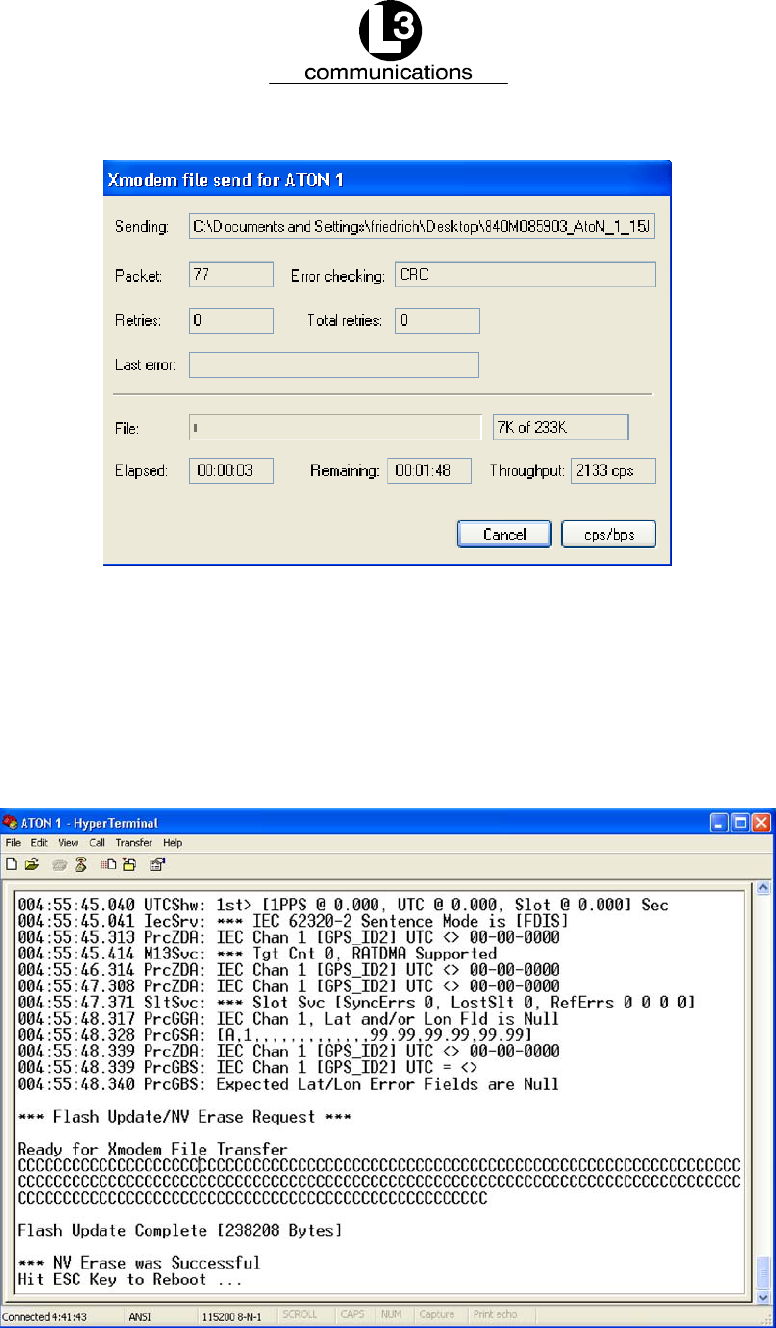
(5) Select the file by double--clicking on it in the file list. Click the “Send” button in
the “Send File” window. As shown in Figure B--2, this begins the actual transfer.
Marine Systems
Aviation Recorders
Page B--3
Rev. 9165M0829--00
October 17/08
Figure B--2. ARM Firmware Update Transfer Screen
(6) When the binary file is completely transferred, Figure B--3 appears, displaying
the image size and a message that the erase of the NV was successful. The
message “Hit ESC to Reboot” also appears. Press Esc to reboot. Trace mes-
sage should begin to be displayed on the screen.
Figure B--3. Firmware Update Successful Message

Marine Systems
Aviation Recorders
Page B--4
165M0829--00Rev. 9
October 17/08
B.2. Recovery Mode of ARM Code Update
Occasionally, the ARM code image in flash memory can be corrupted by an interrup-
ted download or improper programming of the flash during production. If the flash is
corrupted, a two--step process is required to load a flash image.
NOTE: This method of updating the ARM code works whether
there is an image in Flash or not. However, it is the
only method that loads an ARM image if the Flash im-
age is not present or is corrupt.
(1) Install a jumper on the AtoN Baseband board. Connect the Communications/-
Sensor port to “HyperTerminal” at “115200 Baud.” The BMS jumper must be
installed on the Baseband Board at PL10, between pins 13 and 14. PL10 is the
14--pin header located at the board edge near the Atmel AT91RM9200 pro-
cessor device. Pins 13 and 14 are the end pins of both rows of PL10 at the end
nearest the slot cutout in the PC board that allows the RF connector to be
accessed.
(2) Power up the AtoN. The “HyperTerminal” console displays “C” characters at
around one per second.
(3) When the “C” characters are displayed, the ARM code update can begin. On
the “HyperTerminal” menu pull--down bar, click “Transfer” and “Send File.”
(4) When the “Send File” screen opens, click the arrow in the “Protocol” box and
select “Xmodem.”
(5) Click the “Browse” button and find the ARM binary images in the window,
usually located in the “Aton Images” folder. Double--click on “SerBoot.bin” file.
(6) In the “Send File” window, click the “Send” button. This begins the actual trans-
fer, as shown in Figure B--2.
(7) When the transfer ends, “C” characters are automatically generated.
(8) Click the “Browse” button and find the ARM binary images in the window,
usually located in the “Aton Images” folder. A sample file is “AtoN_1_14K.bin.”
The name corresponds to Rev 1.14K of the ARM code. Unless otherwise
directed, select the file with the highest version number.
(9) Double--click on the binary file. Click the “Send” button in the “Send File” win-
dow. This begins the transfer of the binary image.
(10) When the binary file is completely transferred, “C” characters are automatically
generated on the screen.

Marine Systems
Aviation Recorders
Page B--5
Rev. 9165M0829--00
October 17/08
(11) Remove the BMS jumper and power the board up again. The unit should boot
normally and trace messages should appear in the “HyperTerminal” window.

Marine Systems
Aviation Recorders
Page B--6
165M0829--00Rev. 9
October 17/08
THIS PAGE IS INTENTIONALLY LEFT BLANK.

Marine Systems
Aviation Recorders
Page C--1
Rev. 9165M0829--00
October 17/08
Return Material Policy
The maintenance philosophy for the AIS AtoN is replacement of failed assemblies. In the unlikely case of a failure, the
entire unit should be sent back to the factory.
Attempts by anyone but an authorized L--3 representative to repair the AIS AtoN will void the warranty.
Components and spare parts purchased from L--3 that are discrepant for any of the following
reasons may be returned immediately, provided the extended value of the parts is in excess of
$100.00.
1. Overshipments
Quantity of parts received in excess of quantity specified on purchase order.
2. Wrong Part Numbers
Receipt of parts numbered other than those identified on a customer order where L--3 has
not advised the customer by purchase order acknowledgment, by telex, or by notification
on the shipping document that the received part is a replacement for the ordered part.
3. Parts Nonconforming to Specifications
If the extended value of the items is less than $100.00, the items are to be scrapped
instead of returned. When this occurs, notification must be sent to L--3 advising: (1) the
reason for the rejection; (2) the items are less than $100.00 in extended value and have
been scrapped, and; (3) whether credit or replacement is desired.
If you wish to return material to L--3 for reasons other than warranty returns or those specified
above, please contact an L--3 Account Administrator for authorization before proceeding. A
Return Authorization Number will be assigned at this time. Your request should specify the
relevant Return Authorization Number, purchase order number, part number, quantity, and the
reason you wish the part returned.
To assist us in processing these items more efficiently, we ask that all returned goods be
accompanied by paperwork that clearly indicates the following:
1. Reason for return
2. Purchase Order Numbers
3. Correspondence Reference Number
4. Return Authorization Number

Marine Systems
Aviation Recorders
Page C--2
165M0829--00Rev. 9
October 17/08
4. Copies of returned goods paperwork should be mailed to:
L--3 COMMUNICATIONS CORPORATION
AVIATION RECORDERS DIVISION
P. O. Box 3041
Sarasota, FL 34230--3041
Attn: Tom Meloche / Marine Systems Product Support Department
5. Parts returned under the above conditions should be addressed to:
L--3 COMMUNICATIONS CORPORATION
AVIATION RECORDERS DIVISION
6000 E. Fruitville Road
Sarasota, FL 34232
Attn: SERVICE DEPARTMENT
Component and spare parts purchased from L--3 that have been on the customer’s shelf for
more than 10 weeks from date of receipt or have been installed in a component or on a vessel,
are not covered by this procedure. Such parts may be covered by warranty in which case they
should be returned through normal warranty channels.
For repair service, call or email to obtain a Repair Form:
L-3 Communications, Aviation Recorders
6000 E. Fruitville Road
Sarasota, FL 34232 USA
Attn: Repair Department
Tel: (941) 377-5558
Fax #: (941) 377-5585

Marine Systems
Aviation Recorders
Page C--3
Rev. 9165M0829--00
October 17/08
RETURN OF MATERIAL UNDER WARRANTY
1. Material should be returned to the following address:
L--3 COMMUNICATIONS CORPORATION
AVIATION RECORDERS DIVISION
6000 E. Fruitville Road
Sarasota, FL 34232
Attn: WARRANTY RETURNS
2. For returning overseas shipments, the following customs broker must be used:
L--3 COMMUNICATIONS CORPORATION
AVIATION RECORDERS DIVISION
c/o A.J. Arango
Air Cargo Bldg.
4700 N. Hoover Blvd.
Tampa International Airport
Tampa, Florida 33634
Tel: (813) 248--9220
Fax: (813) 248--6013
To ensure prompt handling of material returned under warranty, your return order and
shipment should clearly identify the item as a warranty return, and a copy of such return
order should accompany the shipment. Status of warranty in process will be provided by
the Warranty Administrator.
3. Warranty claims and warranty return orders pertaining to components and spare
parts returned should be mailed to the following address:
L--3 COMMUNICATIONS CORPORATION
AVIATION RECORDERS DIVISION
P. O. Box 3041
Sarasota, FL 34230--3041
Attn: Marine Systems Warranty Administrator
Tel: (941) 377--5574
Fax: (941) 377--5591
RETURNED GOODS
Goods returned to stock for credit, at the request of the Buyer, and authorized by the Seller,
will be subject to a restocking charge of 10% of the purchase price if notified within 30 days of
the order, and 25% of the purchase price if notified after 30 days of the order.

Marine Systems
Aviation Recorders
Page C--4
165M0829--00Rev. 9
October 17/08
CANCELLATION CHARGE
Any order wishing to be canceled must be approved by the pertinent Account Administrator
and may be accountable for a cancellation fee of 15%. This cancellation fee shall take into
account expenses already incurred and commitments made by L--3.