ADC Telecommunications DAS8M-4IDEN-W In-building distributed antenna system User Manual J bonnie john front cover eps
ADC Telecommunications Inc. In-building distributed antenna system J bonnie john front cover eps
Contents
Part 2 users manual
2LGCell Equipment
This section describes the LGCell equipment and explains how the system operates
and contains LGCell system specifications.
For details about cables and connectors, refer to Appendix A – Cables, Connectors,
and Accessories.
LGCell has no user-serviceable parts. Faulty or failed units may be
repaired or replaced through LGC Wireless. In the U.S., please contact us
at 1-800-530-9960. International customers, please contact us at
+1-408-487-2400.
Contents
LGCell Equipment
Standard Equipment. . . . . . . . . . . . . . . . . . . . . . . . . . . . . . . . . . . . . . . . . . . . . . . . 3
Main Hub . . . . . . . . . . . . . . . . . . . . . . . . . . . . . . . . . . . . . . . . . . . . . . . . . . . . . . . . 3
Expansion Hub. . . . . . . . . . . . . . . . . . . . . . . . . . . . . . . . . . . . . . . . . . . . . . . . . . . 10
Remote Antenna Unit (RAU) . . . . . . . . . . . . . . . . . . . . . . . . . . . . . . . . . . . . . . . 13
LGCell System Specifications. . . . . . . . . . . . . . . . . . . . . . . . . . . . . . . . . . . . . . . 16
Band Selective Option . . . . . . . . . . . . . . . . . . . . . . . . . . . . . . . . . . . . . . . . . . . . . 20

2-2 LGCell Equipment
2-3
Standard Equipment
The LGCell standard equipment supports 800 MHz AMPS/TDMA/CDMA/iDEN,
900 MHz GSM, 1800 MHz DCS, 1800 MHz Korean PCS, 1900 MHz TDMA/
CDMA/GSM, and Dual Band 900 GSM/1800 DCS installations.
LGCell has three modular components:
•Main Hub – 19” rack-mountable
•Expansion Hub – 19” rack-mountable
•Remote Antenna Units (RAUs) – Wall or ceiling mountable
LGCell is shipped with the following items:
•Four rack-mount screws per hub
•Four screws for each RAU
•LGCell Installation and Reference Manual
For cable and accessory information, see Appendix A – Cables,
Connectors, and Accessories.
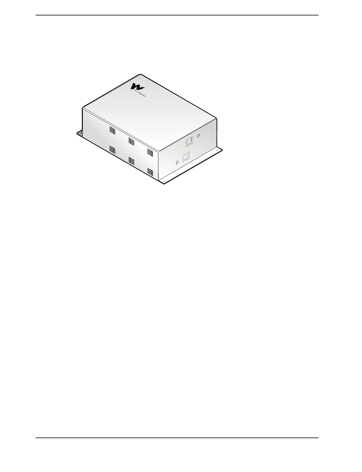
Main Hub
The Main Hub is the LGCell’s central distribution point. It receives downlink
cellular or PCS signals from an MBS or a roof-mounted antenna and redistributes
them to multiple Expansion Hubs in low-frequency signal format (<200MHz),
which can be passed over the MMF and CAT 5 cabling.
2-4 LGCell Equipment
The Main Hub also receives signals from the Expansion Hubs and reconverts them
back to the cellular or PCS band for transmission on the uplink channel (mobile) to
the macrocellular base station (BTS) or microcellular base station (MBS).
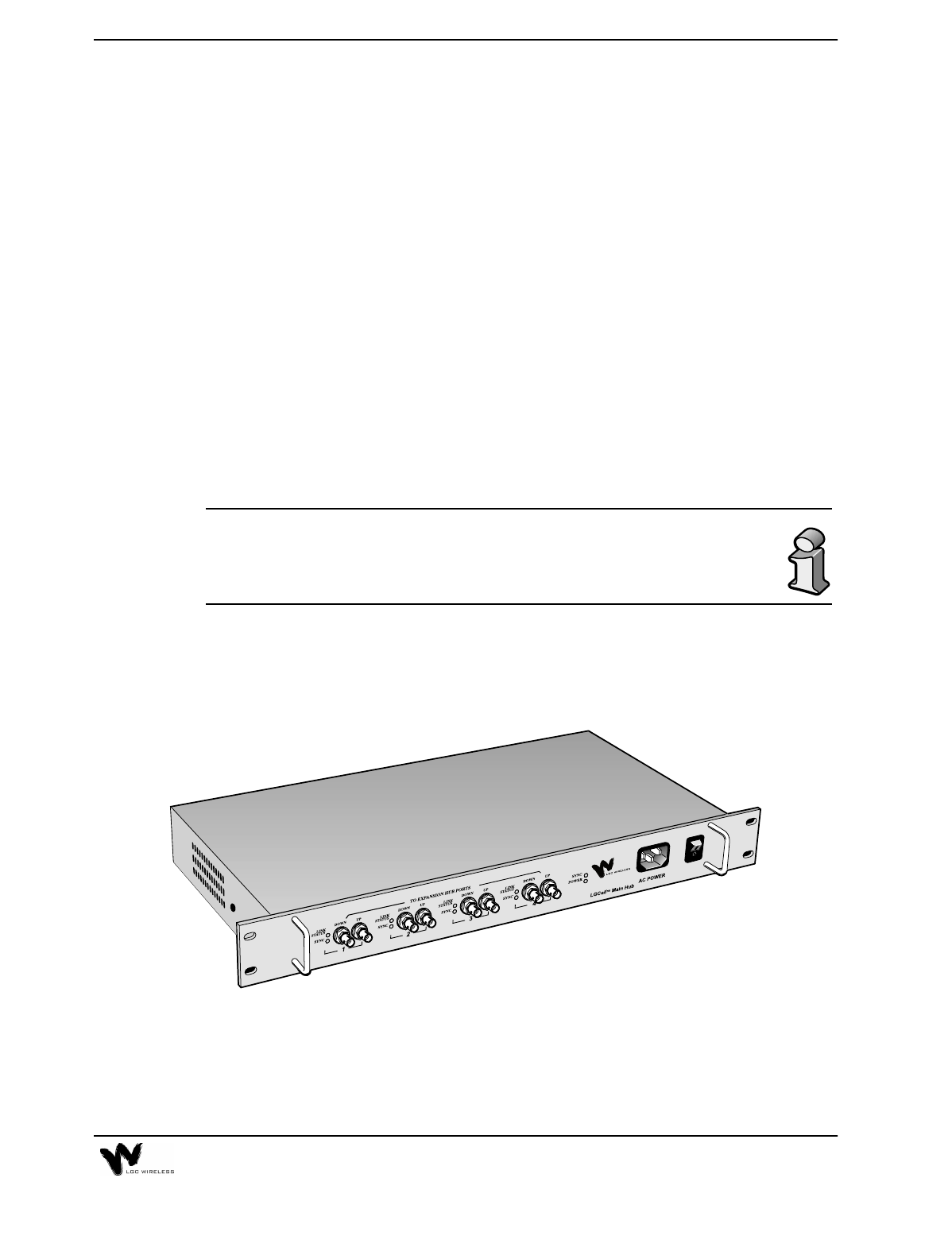
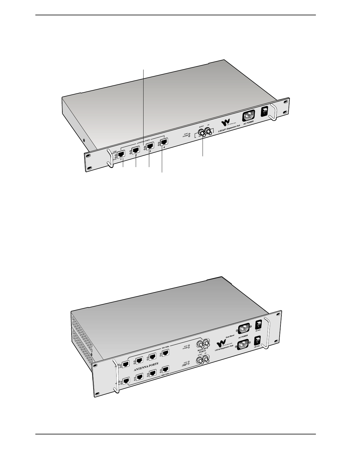
The Dual Band 900/1800 Main Hub is shown below.
Main Hub Features
•Mounts in a standard 19” equipment rack, width 17.25” (438 mm)
•Height is 1.7” (44.5 mm). The Dual Band Main Hub is 3.5” (88.9 mm) high.
•Operates with worldwide AC power, 100-240 VAC at 1.6 A and 50/60 Hz
•Connects up to four Expansion Hubs and 16 RAUs per Main Hub. The Dual
Band Main Hub connects up to four Expansion Hubs and 16 RAUs for the 900
system and an equal number for the 1800 system.
•Connect multiple Main Hubs to increase number of RAUs. See “Connecting
Multiple LGCell Systems” on page 3 in Section 5, Connectivity.
•Connects to a roof-mounted antenna, repeater, or duplexed MBS via one
coaxial cable using an N-type, female, duplexed, bi-directional RF connector
•Connects to MBS via two coaxial cables using two N-type female, simplex RF
connectors
•Connects to Expansion Hubs via MMF fiber cable (up to 1 kilometer)
•Distributes cellular or PCS signals to the Expansion Hubs via standard MMF
transmit and receive pairs
•Has easily accessible connectors
2-5
•Displays system status via front panel LEDs
•Provides contact closure of major alarms and error latches through a D-sub
9-pin connector
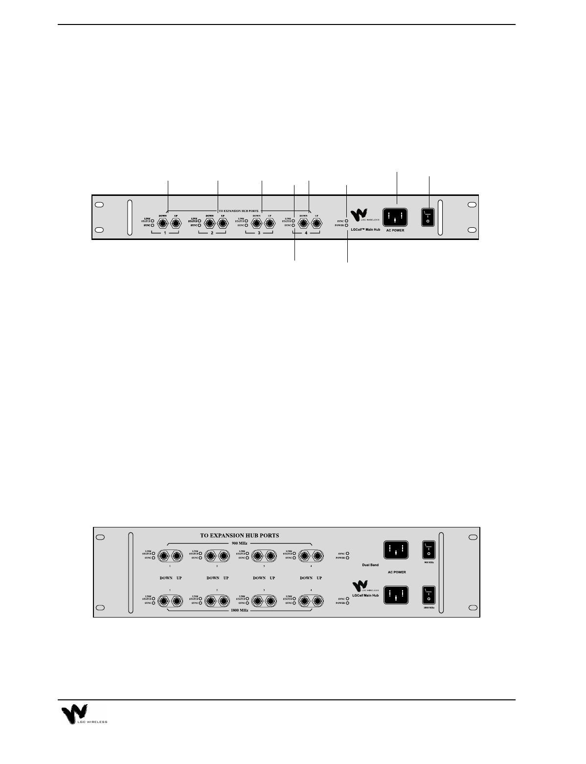
Main Hub Front Panel
Front Panel Description
1AC power cord connector
2Power On/Off switch
3One LED for sync status (labeled SYNC)
4One LED for power (labeled POWER)
5Four Ports (labeled 1, 2, 3, 4)
•One standard female ST-connector for MMF downlink (labeled DOWN)
•One standard female ST-connector for MMF uplink (labeled UP)
6One LED for port RF link status (labeled LINK STATUS)
7One LED for port sync status (labeled SYNC)
The Dual Band Main Hub Front Panel is shown below. The connectors are the same
as those explained for the single band system.
12
3
4
55 5 5 6
7
2-6 LGCell Equipment
Standard MMF Uplink and Downlink Ports
The Main Hub transmits and receives RF signals to and from
the Expansion Hubs using up to 1 kilometer of industry-
standard 62.5µm/125µm MMF cable (up to 1.5 dB optical loss,
approximately 1 kilometer without jumpers).
•Uplink/Input (labeled UP)
This signal is the combination of all uplink signals received
by the Expansion Hubs connected to the system.
•Downlink/Output (labeled DOWN)
The downlink is a composite signal coming from the
duplexed N-type connector or from the downlink simplex
connector on the Main Hub back panel. The downlink signal
is re-radiated at all RAUs.
Main Hub LEDs
LED Color Indication
HUB LEDS
POWER Green On/Off Fault
SYNC Green On/Off Fault
PORT LEDS
SYNC Green
Red Operational
Fault
LINK STATUS Green
Red Operational
Fault
2-7
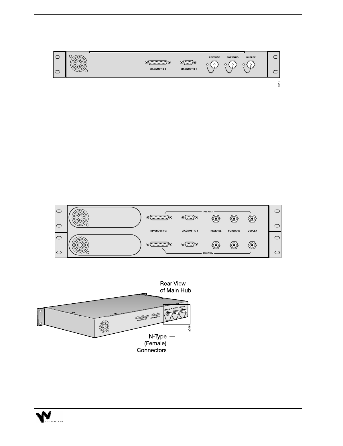
Main Hub Back Panel
Back Panel Description
•Three N-type, Female Connectors with dust caps
•One Duplexed (labeled DUPLEX)
•One Uplink (labeled REVERSE)
•One Downlink (labeled FORWARD)
•One D-Sub 9-pin Connector (labeled DIAGNOSTIC 1)
•One D-sub 25-pin Connector (labeled DIAGNOSTIC 2)
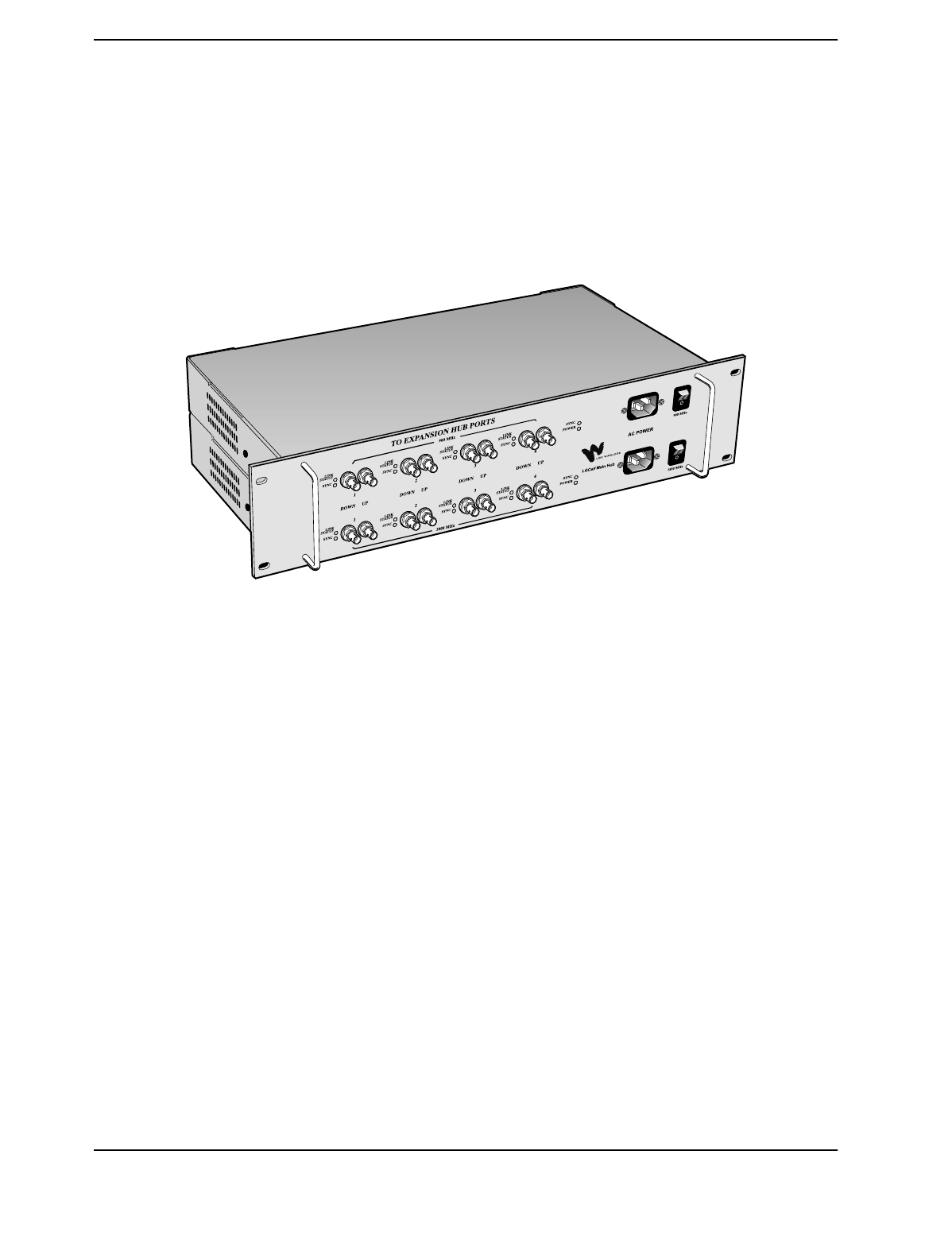
The Dual Band Main Hub Back Panel is shown below. The connectors are the same
as shown for the single band LGCell Main Hub.
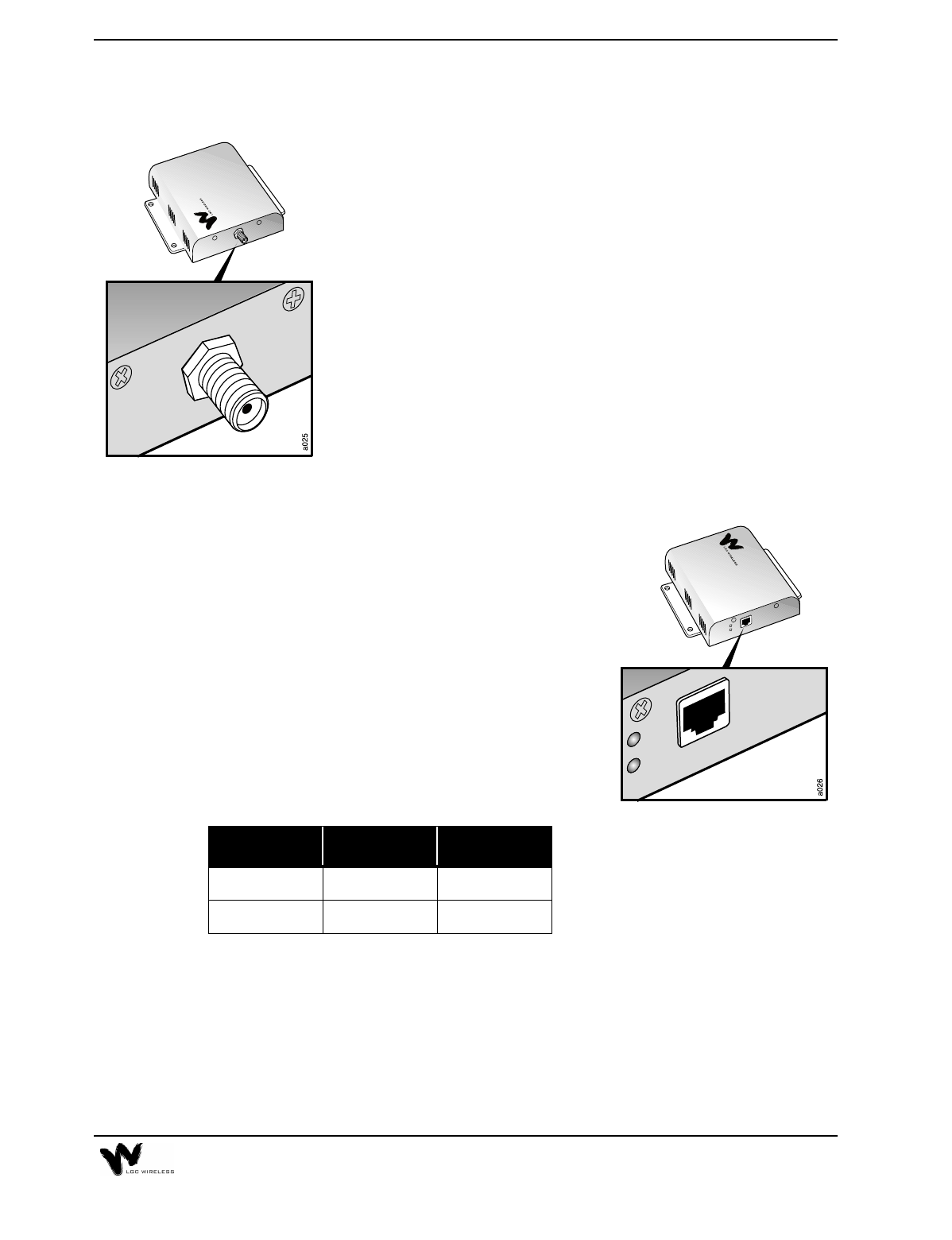
N-Type Female Connectors
The N-type, female connectors
connect the coaxial cable from the
roof-mounted antenna, repeater, or
MBS to the Main Hub for RF
connection. These cable connectors
are operational in the cellular and PCS
frequency bands.
See Maximum Input RF Power per
Carrier vs. Number of Carriers, on page 17 in this section for the maximum uplink
and downlink power.
2-8 LGCell Equipment
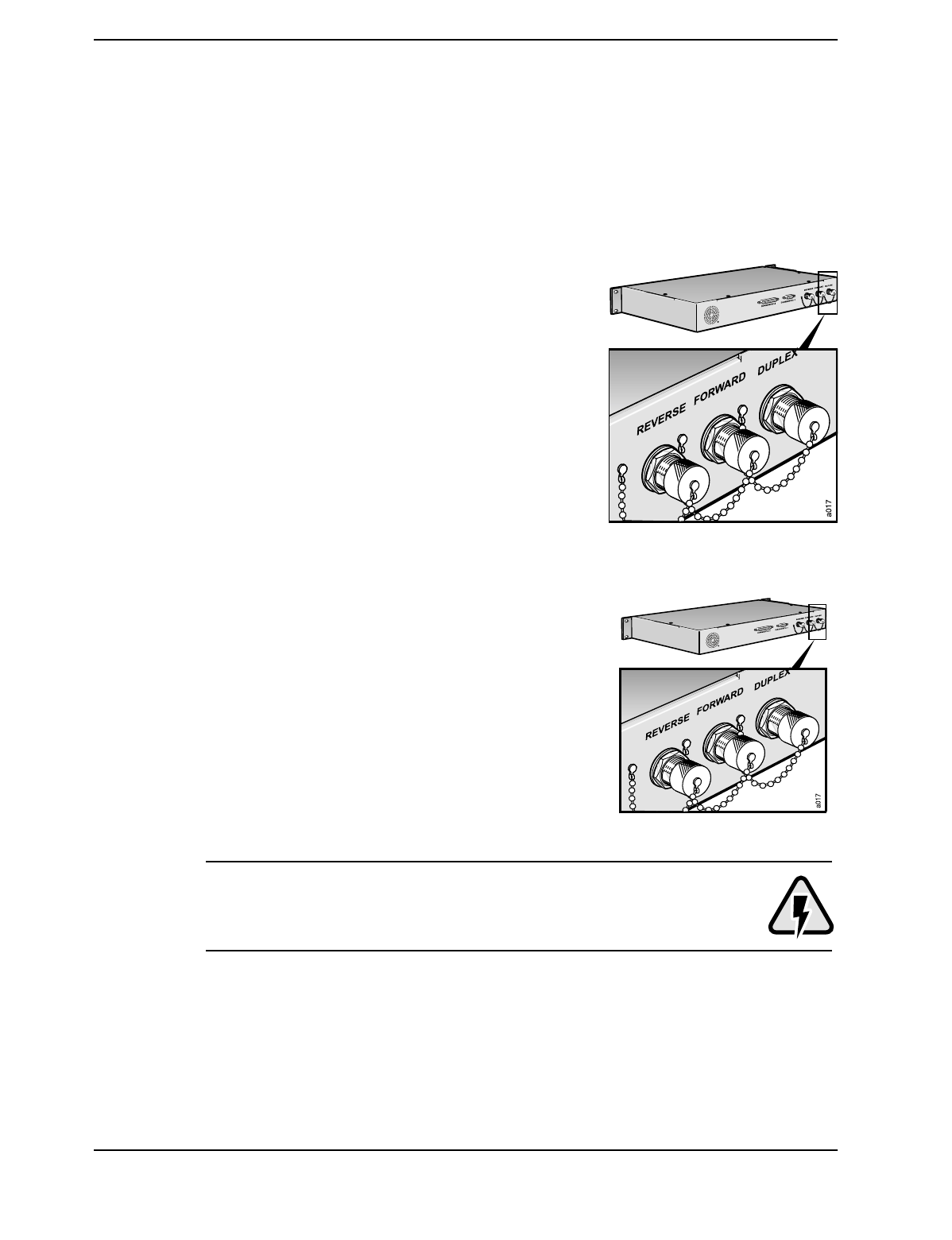
There are three N-type female connectors:
Duplexed: Output and Input (bi-directional)
Uplink: Simplex Output (unidirectional)
Downlink: Simplex Input (unidirectional)
•Duplexed (labeled DUPLEX)
The DUPLEX connector is for a duplexed
connection. This connector provides both
downlink and uplink signals to and from the
roof-mounted antenna, repeater, or MBS to the
Main Hub. This duplex port provides a 30 or 40
dB gain on the duplex part. See “LGCell
System Gain” on page 17.
•Uplink (labeled REVERSE) and
Downlink (labeled FORWARD)
The uplink and downlink connectors are for a
simplex connection. The FORWARD connector
receives RF signals and the REVERSE connector
transmits RF signals to and from the roof-
mounted antenna, repeater, or MBS.
DO NOT exceed the maximum input power into the Main Hub. See
Maximum Input RF Power per Carrier vs. Number of Carriers, on page
17 in this section.
2-9
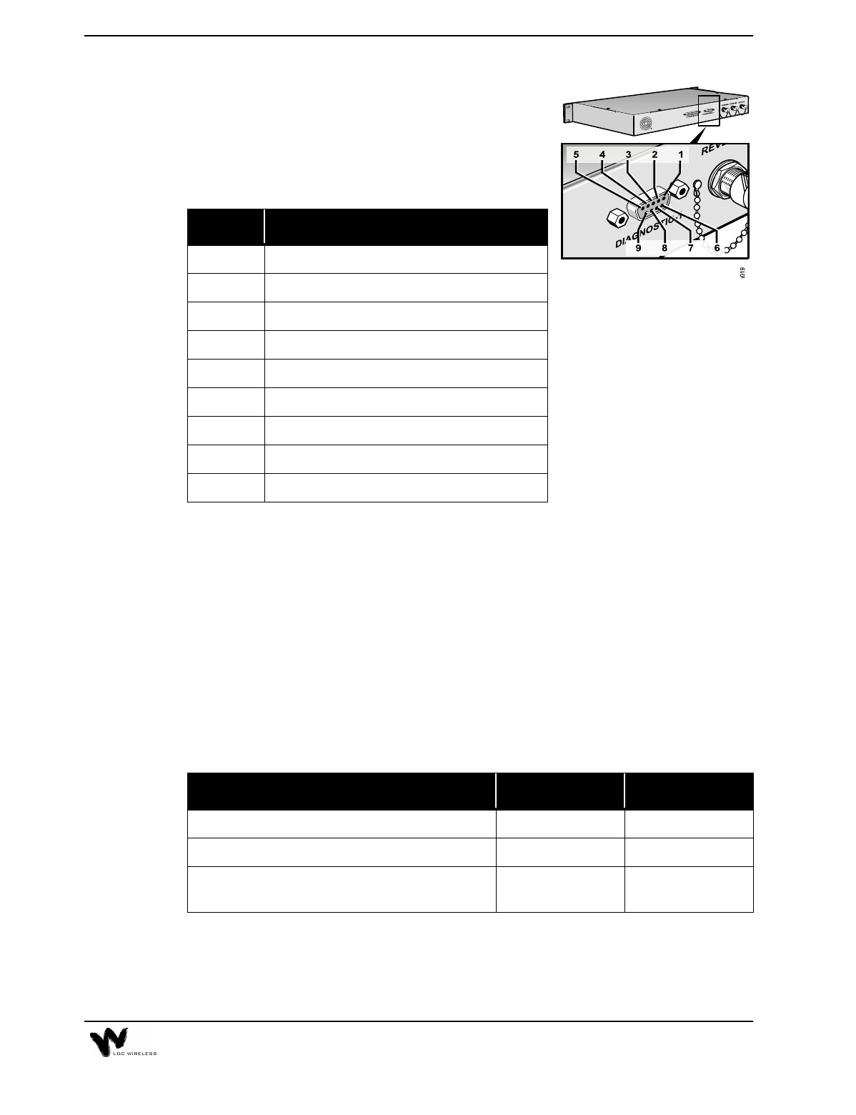
D-Sub 9-Pin Connector
The D-Sub 9-pin connector (labeled DIAGNOSTIC 1)
provides contact closure for major and latch system
alarm monitoring. The following table lists the
function of each pin on the D-sub 9-pin connector.
Alarms
LGCell provides full Operations Alarm Maintenance and Provisioning (OAM&P).
The Main Hub senses then latches major alarms. An error latch provides historical
information for troubleshooting.
The major alarms and error latches are monitored with contact closures. Alarms can
be sent to remote locations (see Section 5, Connectivity and Section 6,
Troubleshooting). For details about alarm monitoring, see Appendix E – Alarm
Report Monitor (ARM2000).
The two error connections, Major Error and Error Latch, are relay connections.
They are either open or short circuit (see the following table).
When you use these error pin connections, determine the error status by sending a
current of no more than 40 mA through the positive connection and returning it
through the negative connection. An error is indicated if current ceases to flow
through the error connection.
Pin Function
1+10 V (fused)
2 Not connected
3 Not connected
4 Error Latch (positive connection)
5 Error Latch (negative connection)
6 DC Ground
7 Major Error (positive connection)
8Error Reset
9 Major Error (negative connection)
Operation Major Error Error Latch
Proper Operation Short Circuit Short Circuit
Error Open Circuit Open Circuit
Proper Operation but had error and system latched;
alarm was not reset Short Circuit Open Circuit
2-10 LGCell Equipment
Expansion Hub
The Expansion Hub is LGCell’s intermediate distribution point.
It transmits and receives low frequency signal (<200MHz) to and from the Main
Hub, and to and from the RAUs. Utilizing LGC Wireless’ proprietary technology,
both the MMF and the UTP/STP cables can transmit signals in the cellular or PCS
frequency bands.
The Dual Band 900/1800 Expansion Hub is shown below:
Antenna Ports
Main Hub Port
1234
2-11
Expansion Hub Features
•Mounts in a standard 19" equipment rack, with 17.25” (438 mm)
•Height is 1.7" (44.5 mm). The Dual Band Expansion Hub is 3.5” (88.9 mm)
high.
•Operates with worldwide AC power, 100-240 VAC at 1.6 A and 50/60 Hz
•Connects up to four RAUs. The Dual Band Expansion Hub connects up to four
RAUs for the 900 system and up to four RAUs for the 1800 system.
•Connects to the Main Hub with MMF transmit/receive cable (up to 1.5 dB
optical loss, approximately 1 kilometer without jumpers)
•Connects up to four RAUs via four RJ-45 connectors that feed RAUs directly
through a UTP/STP cable
•Provides DC power to RAUs through the UTP/STP cable
•Has easily accessible connectors
•Displays system operation via front panel LEDs
•Communicates with Main Hub for system alarm status
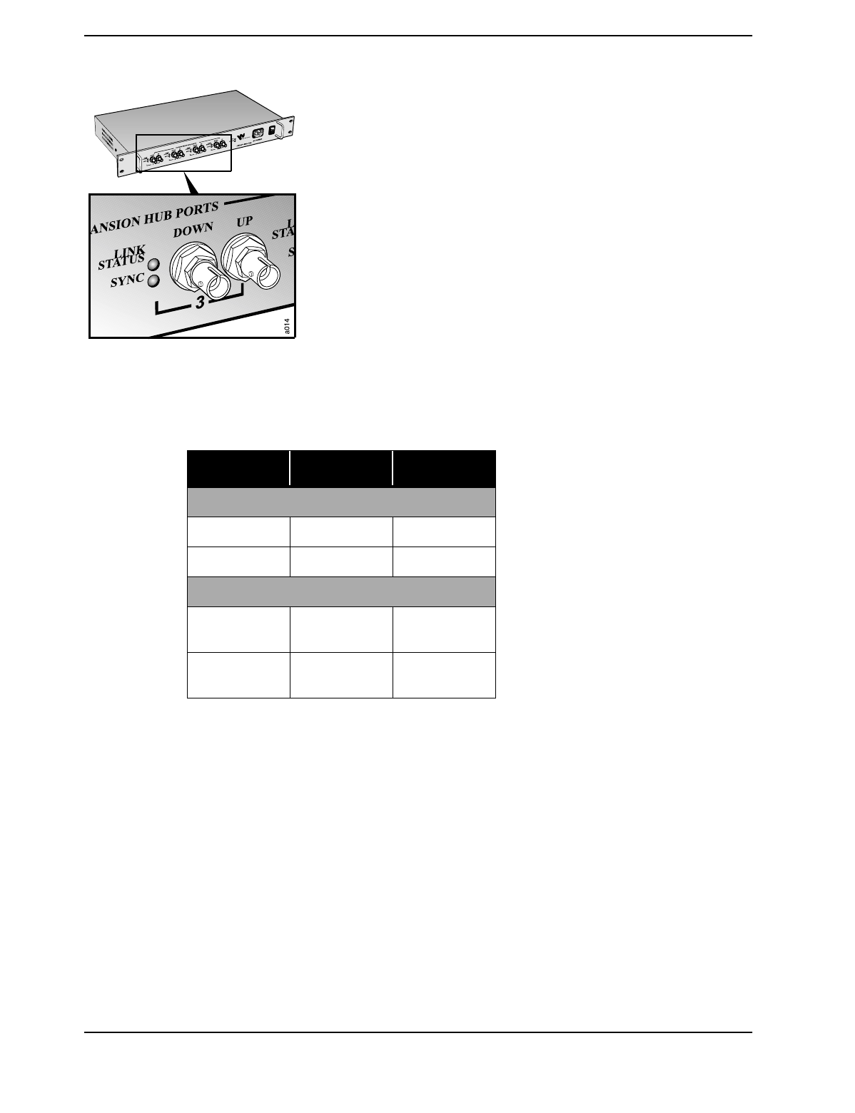
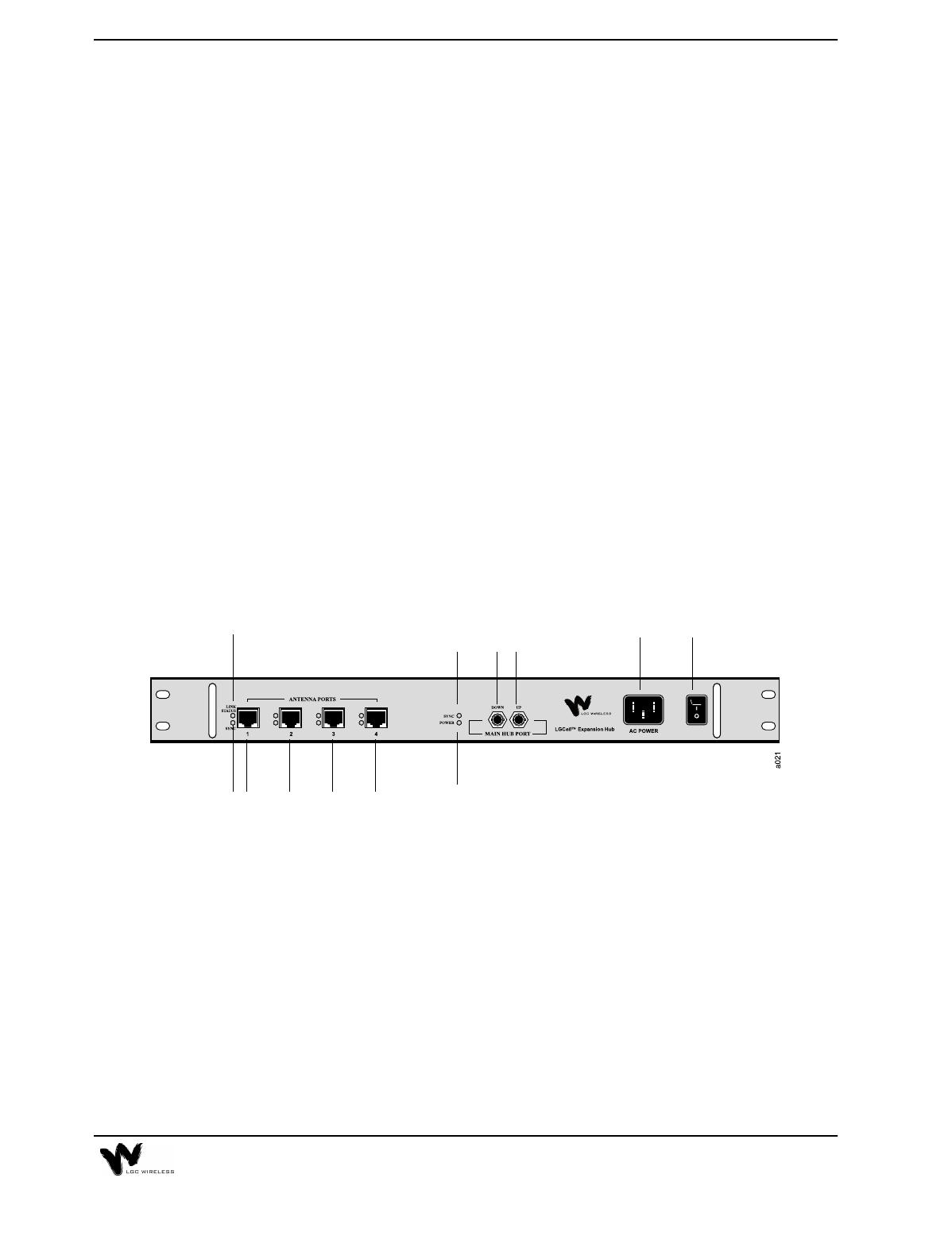
Expansion Hub Front Panel
Expansion Hub Description
1AC power cord connector
2Power On/Off switch
3In Fiber Port (labeled MAIN HUB), one standard ST connector for MMF
downlink (labeled DOWN)
4In Fiber Port (labeled MAIN HUB), one standard ST connector for MMF uplink
(labeled UP)
5One LED for port sync status (labeled SYNC)
6One LED for power (labeled POWER)
7Four standard UTP/STP CAT 5 Cable RJ-45 female connectors (labeled
ANTENNA PORTS 1, 2, 3, and 4)
1 2
35
6
7
4
777
(Labeled 1, 2, 3, and 4)
9
8
2-12 LGCell Equipment
8One LED to monitor RF link status (labeled LINK STATUS)
9One LED to monitor sync status (labeled SYNC)
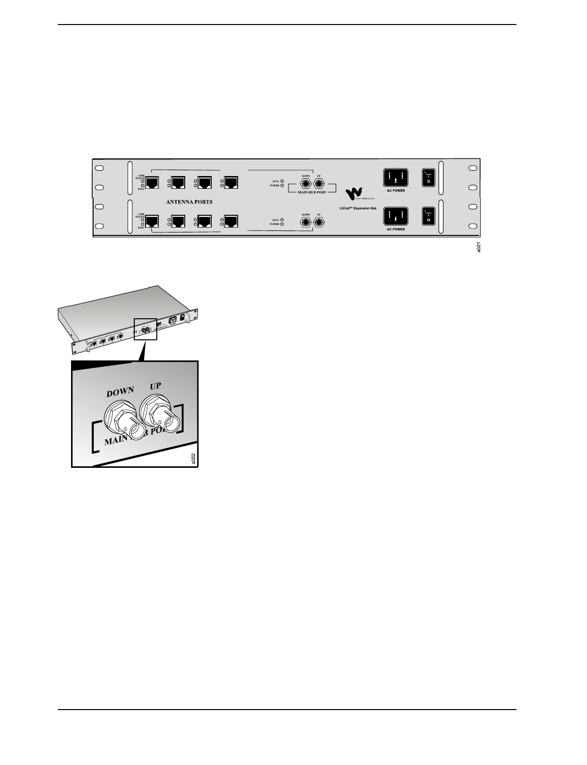
The Dual Band Expansion Hub Front Panel is shown below. The connectors are the
same as those explained for the single band system.
Standard MMF Uplink and Downlink Port
The Expansion Hub transmits and receives cellular or PCS signals
to and from the Main Hub using up to 1 kilometer of industry-
standard 62.5µm/125 µm MMF cable found in most buildings.
•Uplink/Output (labeled UP)
The uplink is the combination of all uplink signals received by the
RAUs. The signals are fed into the Expansion Hub via the UTP/STP
cables. The Expansion Hub then transmits the combination of all
signals to the Main Hub via the MMF cable.
•Downlink/Input (labeled DOWN)
The Expansion Hub receives downlink signals from the Main Hub
via the other MMF port. The downlink signals are subsequently re-
radiated at all RAUs via the UTP/STP cable.
DUAL BAND
900 MHz
1800 MHz
2-13
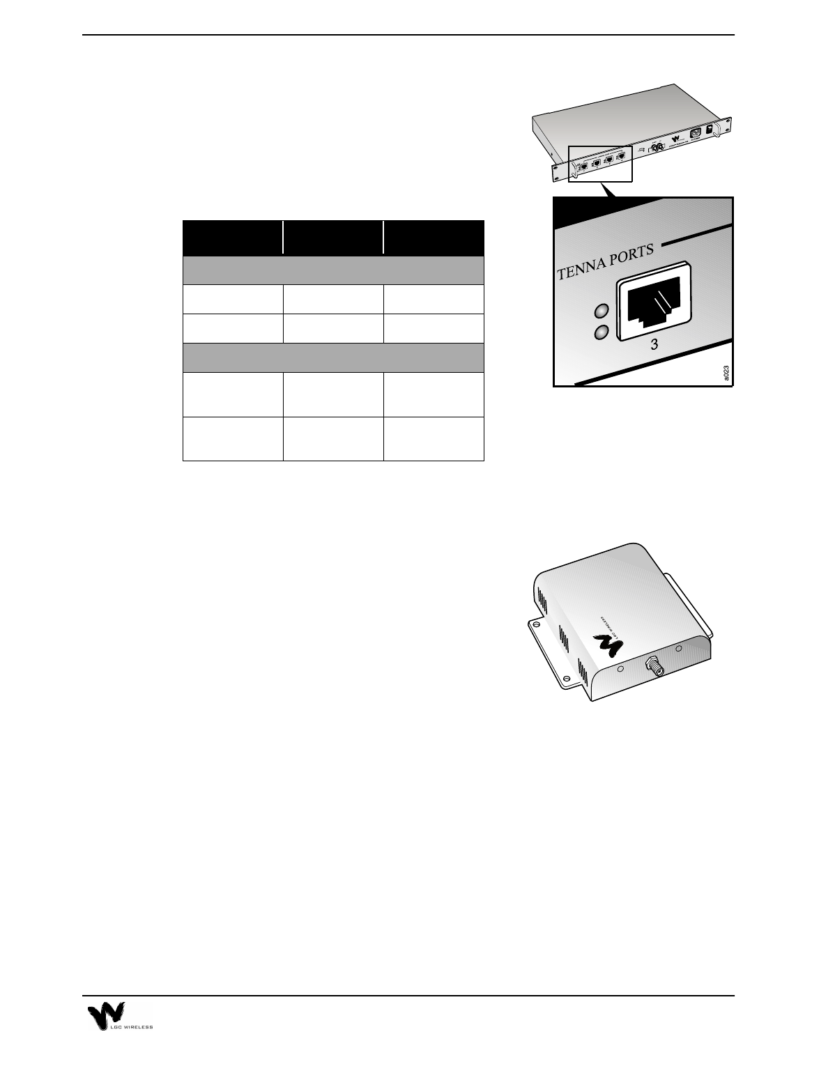
UTP/STP CAT 5 Cable Connectors
Delivers electrical power to the RAUs. Also
transmits downlink signals and receives uplink
signals to and from the RAUs.
Expansion Hub LEDs
Remote Antenna Unit (RAU)
RAU Description
•One female SMA connector
•One Standard CAT 5 UTP/STP RJ-45
female receptacle
•Two LEDs
•One for antenna power
•One for antenna sync indication
LED Color Indication
HUB LEDS
POWER Green On/Off Fault
SYNC Green On/Off Fault
PORT LEDS
SYNC Green
Red Operational
Fault
LINK STATUS Green
Red Operational
Fault
2-14 LGCell Equipment
The Dual Band 900/1800 RAU is shown here. The Dual Band RAU has the same
connectors as the single band RAU. It has one set of connectors for the 900 RAU
and one set for the 1800 RAU.
RAUs are active antennas that connect directly to an Expansion Hub over standard
CAT 5 (or better) UTP/STP cable. The cable also delivers electrical power to the
antenna.
RAUs receive uplink cellular or PCS signals and re-transmits them to an Expansion
Hub in a low frequency signal format (<200MHz).
They also receive signals from the Expansion Hub, and re-convert the signals back
to the cellular or PCS band for transmission on the downlink.
RAU Features
•Transmits to Expansion Hubs via an RJ-45 connector using UTP/STP cable
•Uses an SMA connector for standard in-building antennas
•Has easily accessible connectors
•Displays system operation via LEDs
•Dimensions: 5.7" x 5.5" x 1.2" (145 mm x 140 mm x 30 mm). The dimensions
for the Dual Band RAU are 8” x 6.2” x 2.7” (1626 mm x 157 mm x 69 mm).
•Connects to Expansion Hub via one RJ-45 connector that feeds RAUs directly
through a UTP/STP cable (up to 60 meters)
For system performance for cable lengths greater than 60 meters, see “LGCell
System Gain vs. UTP/STP Cable Length (800 MHz, iDEN, 900 MHz)” on page 6
and “LGCell System Gain vs. UTP/STP Cable Length for 1800 MHz or 1900 MHz
(Horizontal run, measured with 1 km of Multi-Mode Fiber)” on page 7 in
Appendix A – Cables, Connectors, and Accessories.
2-15
RAU Connectors
SMA Connector
The SMA connector on the RAU is a duplexed RF input/output
port that connects to standard in-building antennas.
•Uplink (Input)
The uplink cellular or PCS channels are received from the
mobile phone by the in-building antenna. For the maximum
downlink composite radiated power at the RAU, see the table
on page 17 in this chapter.
•Downlink (Output)
The downlink channels are transmitted (radiated) by the
standard in-building antenna. For the maximum downlink
composite radiated power at the RAU, see the table on page 17
in this chapter.
Standard CAT 5 UTP/STP RJ-45 Jack
Delivers electrical power to the antenna. Also
transmits and receives uplink and downlink signals
to the Expansion Hub.
RAU LEDs
If the antenna SYNC LED lights red, RF power in the antenna is automatically shut
down. The antenna RF power is reset when the SYNC LED goes off.
LED Color Indication
POWER Green On
SYNC Red Fault
2-16 LGCell Equipment
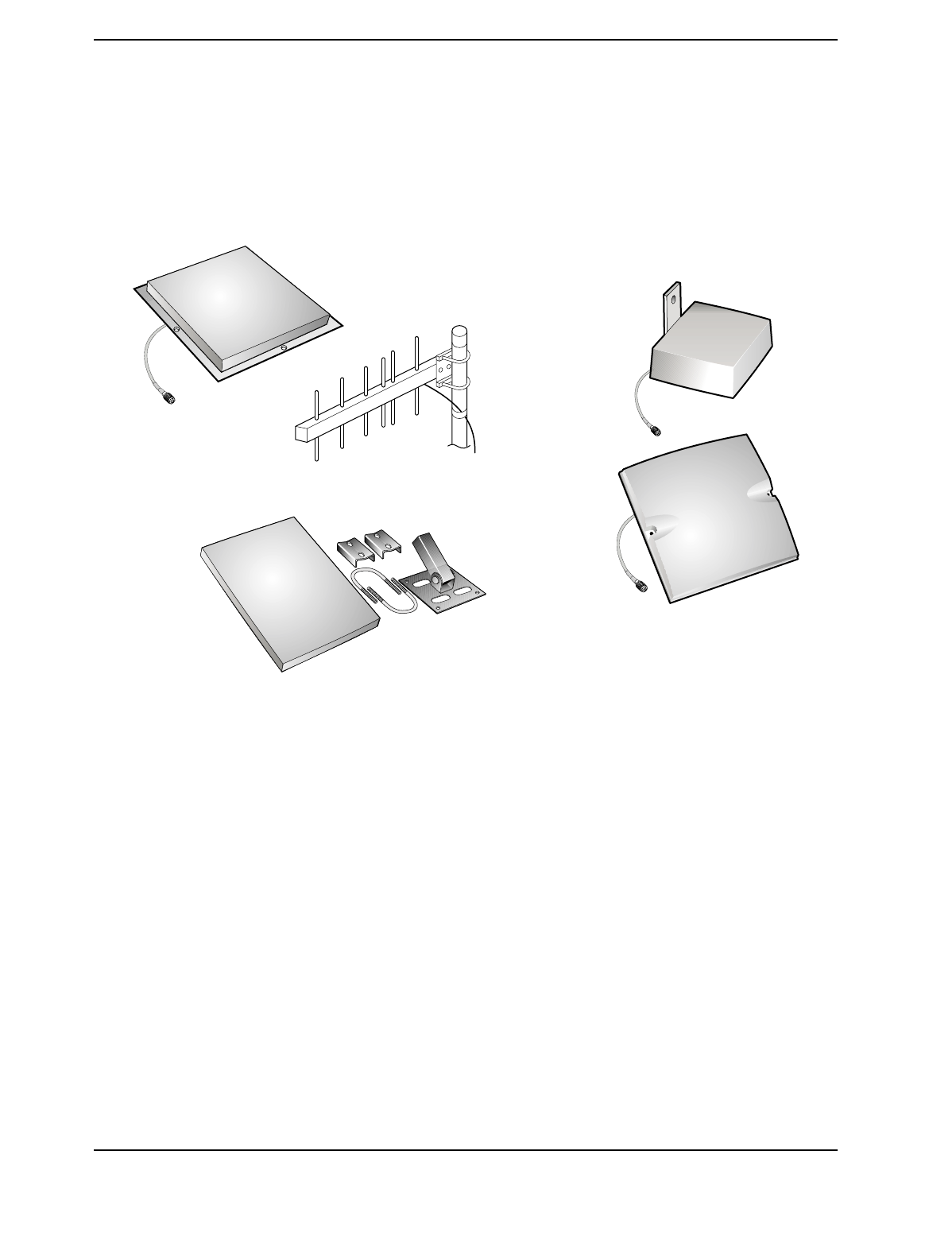
RAU Optional Antennas
The following illustration shows optional antennas that can plug into the SMA
connector. For recommended antennas, refer to the accessory section in the LGCell
Price List or contact your account manager.
LGCell System Specifications
The following tables give system specifications for LGCell.
•System gain, maximum input/output RF Power
•Maximum Input Power per Carrier vs. Number of Carriers
2-17
LGCell System Gain
This table is a summary of the system gain for different frequencies and formats.
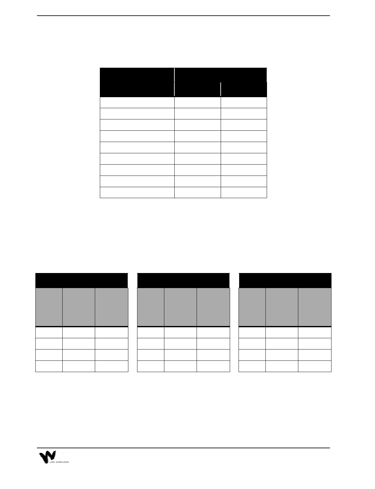
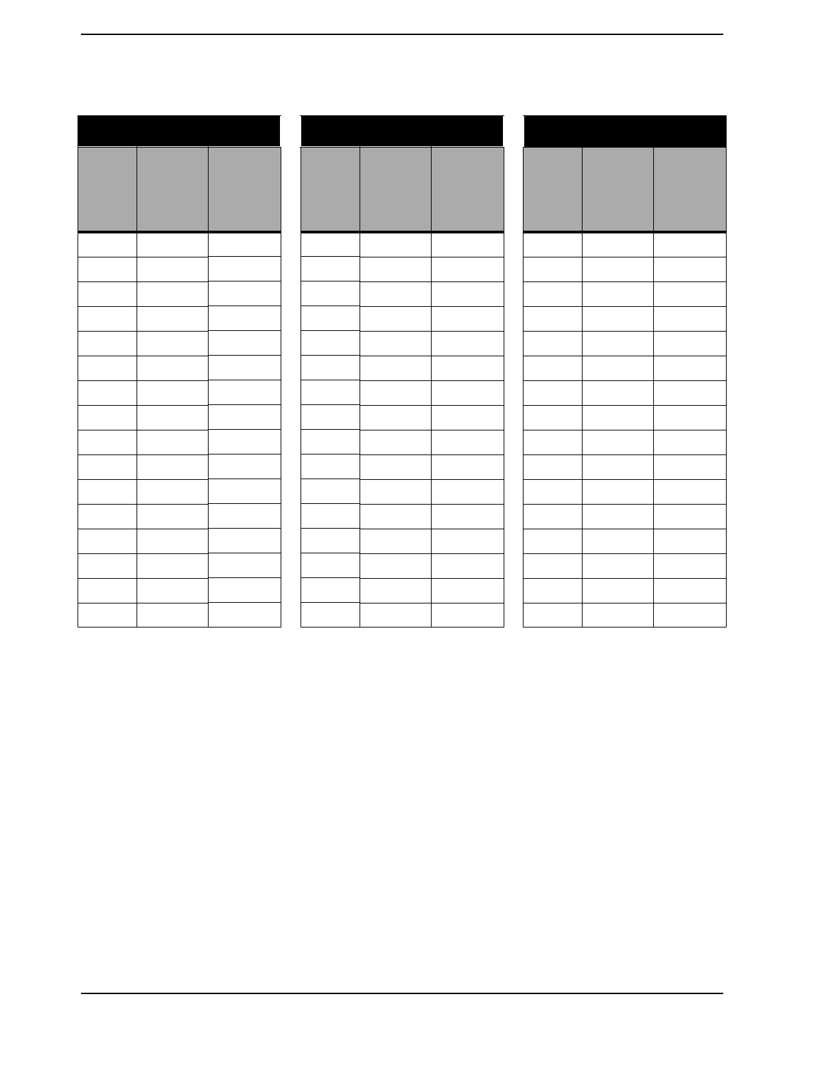
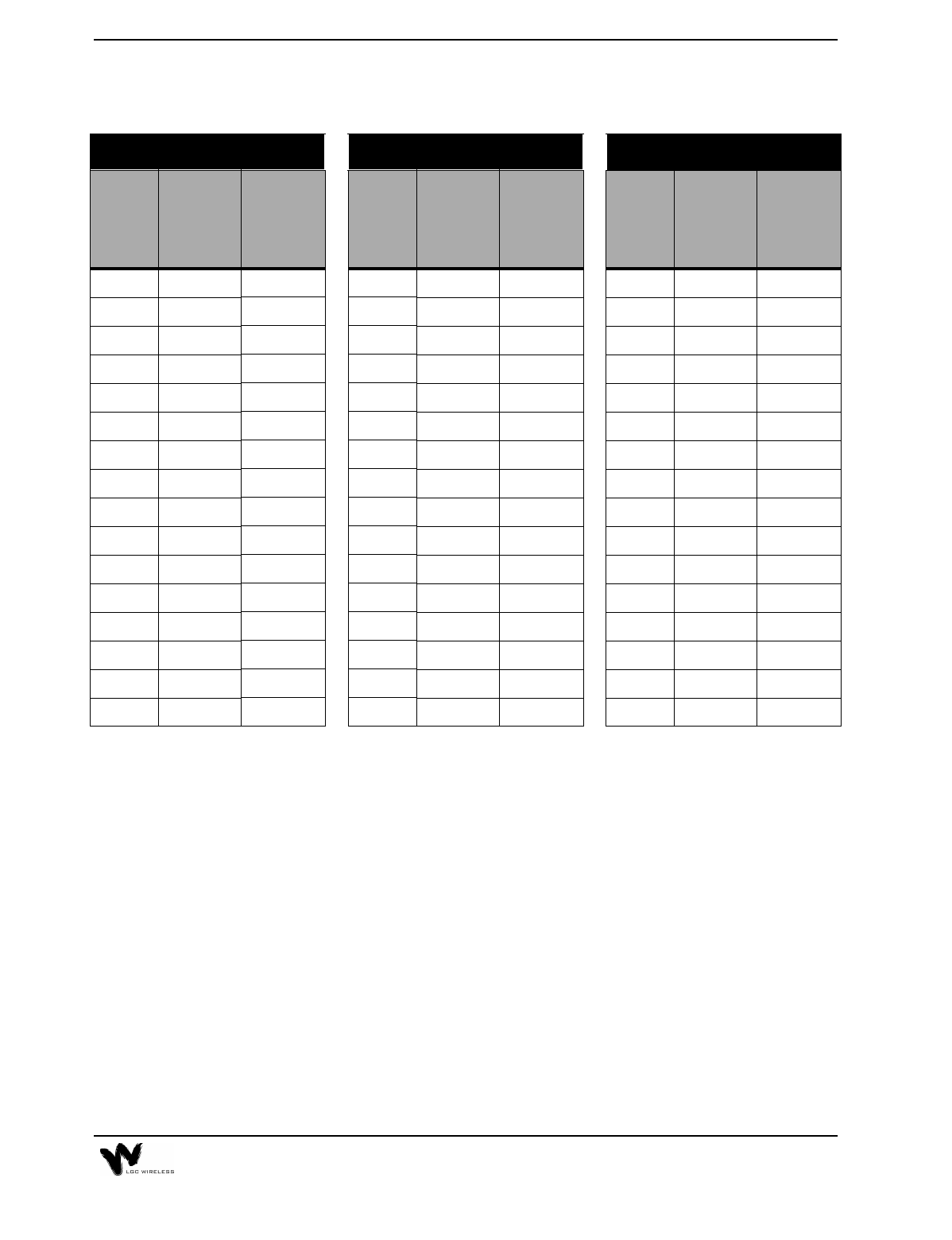
Maximum Input RF Power per Carrier vs. Number of Carriers
When you connect a Main Hub to an MBS that supports several RF carriers, the RF
power per carrier must be cut back so as not to exceed the total composite radiated
power into the Main Hub DUPLEX or FORWARD connector. The following table
shows the maximum power per carrier and maximum composite power for different
frequencies, formats, and numbers of carriers.
LGCell
Frequency/Format
System Gain
Duplex Simplex
800 MHz AMPS, TDMA 30 0
800 MHz CDMA 30 0
800 MHz iDEN 0 0
900 MHz GSM 0 0
1800 MHz CDMA 0 0
DCS 1800 GSM 0 0
1900 MHz TDMA 40 0
1900 MHz CDMA 40 0
1900 MHz GSM 40 0
800 CDMA 1800 Korean CDMA 1900 TDMA
Number
of
Carriers
Maximum
Power
per
Carrier
Maximum
Composite
Power
Number
of
Carriers
Maximum
Power
per
Carrier
Maximum
Composite
Power
Number
of
Carriers
Maximum
Power
per
Carrier
Maximum
Composite
Power
1 10.0 10.0 1 9.0 9.0 1 10.0 10.0
2 7.0 10.0 2 6.0 9.0 2 7.0 10.0
3 5.2 10.0 3 4.2 9.0 3 5.2 10.0
4 3.0 9.0 4 2.0 8.0 4 3.0 9.0
2-18 LGCell Equipment
800 AMPS 800 TDMA 800 GSM
Number
of
Carriers
Maximum
Power
per
Carrier
Maximum
Composite
Power
Number
of
Carriers
Maximum
Power
per
Carrier
Maximum
Composite
Power
Number
of
Carriers
Maximum
Power
per
Carrier
Maximum
Composite
Power
1 20.0 20.0 1 17.0 17.0 1 20.0 20.0
2 15.5 18.5 2 12.5 15.5 2 8.0 11.0
3 12.8 17.6 3 9.8 14.6 3 6.0 10.8
4 11.0 17.0 4 8.0 14.0 4 4.7 10.7
5 9.5 16.5 5 6.5 13.5 5 3.8 10.8
6 8.3 16.1 6 5.3 13.1 6 3.0 10.8
7 7.3 15.8 7 4.3 12.8 7 2.3 10.8
8 6.5 15.5 8 3.5 12.5 8 2.0 11.0
9 5.7 15.2 9 2.7 12.2 9 1.5 11.0
10 5.0 15.0 10 2.0 12.0 10 1.2 11.2
11 4.4 14.8 11 1.4 11.8 11 0.8 11.2
12 3.8 14.6 12 0.8 11.6 12 0.5 11.3
13 3.3 14.4 13 0.3 11.4 13 0.3 11.4
14 2.8 14.3 14 -0.2 11.3 14 0.0 11.5
15 2.4 14.1 15 -0.6 11.1 15 -0.1 11.7
16 1.9 14.0 16 -1.1 11.0 16 -0.3 11.7
2-19
1800 DCS/GSM 1900 AMPS 1900 TDMA
Number
of
Carriers
Maximum
Power
per
Carrier
Maximum
Composite
Power
Number
of
Carriers
Maximum
Power
per
Carrier
Maximum
Composite
Power
Number
of
Carriers
Maximum
Power
per
Carrier
Maximum
Composite
Power
1 18.0 18.0 1 20.0 20.0 1 17.0 17.0
2 6.0 9.0 2 13.5 16.5 2 12.5 15.5
3 4.0 8.8 3 11.5 16.3 3 9.8 14.6
4 2.7 8.7 4 10.3 16.3 4 8.0 14.0
5 1.8 8.8 5 9.3 16.3 5 6.5 13.5
6 1.0 8.8 6 8.3 16.1 6 5.3 13.1
7 0.3 8.8 7 7.3 15.8 7 4.3 12.8
8 0.0 9.0 8 6.5 15.5 8 3.5 12.5
9 -0.4 9.1 9 5.7 15.2 9 2.7 12.2
10 -0.8 9.2 10 5.0 15.0 10 2.0 12.0
11 -1.1 9.3 11 4.4 14.8 11 1.4 11.8
12 -1.4 9.4 12 3.8 14.6 12 0.8 11.6
13 -1.7 9.4 13 3.3 14.4 13 0.3 11.4
14 -1.9 9.6 14 2.8 14.3 14 -0.2 11.3
15 -2.1 9.7 15 2.4 14.1 15 -0.6 11.1
16 -2.3 9.7 16 1.9 14.0 16 -1.1 11.0
2-20 LGCell Equipment
Band Selective Option
LGCell 800 MHz, 900 MHz, 1800 MHz, and 1900 MHz
The LGCell 800/900 MHz system has fixed bands of operation. The LGCell 1800/
1900 MHZ system has a fixed bandwidth filter in each system that is centered over
the desired band of operation. The desired band of operation is an ordered item
either by band (A, B, D, E, F) or by the center uplink and downlink frequency.
1900 GSM
Number
of
Carriers
Maximum
Power
per
Carrier
Maximum
Composite
Power
1 20.0 20.0
2 8.0 11.0
3 6.0 10.8
4 4.7 10.7
5 3.8 10.8
6 3.0 10.8
7 2.3 10.8
8 2.0 11.0
9 1.5 11.0
10 1.2 11.2
11 0.8 11.2
12 0.5 11.3
13 0.3 11.4
14 0.0 11.5
15 -0.1 11.7
16 -0.3 11.7
2-21
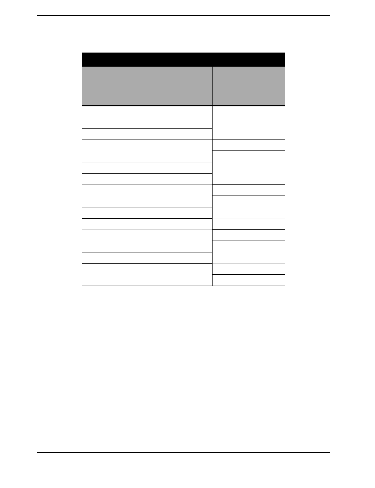
The following table shows the bandwidths for each type of system.
For example, the A band for 1900 MHz PCS has the fixed 15 MHz filter centered
at 1937.5 MHz for the downlink and 1857.5 for the uplink.
1 30 MHz pass filter can be positioned along the 75 MHz DCS 1800 band. Order product with uplink and
downlink frequency at 1.25 MHz spacing. For example an uplink center frequency of 1737.5 MHz will provide
a 30 MHz band between 1722.5 MHz and 1752.5 MHz and a downlink center frequency of 1832.5 MHz will
provide a 30 MHz band between 1817.5 MHz and 1847.5 MHz.
2 Similar to above, the 1900 PCS 15 MHz filter can be positioned along the 60 MHz band.
The LGCell covers a 30 MHz band in frequency range of 1710 MHz to 1785 MHz
on the uplink and 1805 MHz to 1880 MHz on the downlink. The operator can
choose where to place the 30 MHz band of operation by choosing the corresponding
center frequencies as shown in the following table.
System Fixed Filter
Bandwidth Uplink Center
Frequency Downlink Center
Frequency
DAS 800 MHz - AMPS,
TDMA, CDMA
25 MHz 836.5 MHz 881.5 MHz
DAS 800 MHz - iDEN 18 MHz 815 MHz 860 MHz
DAS 900 GSM 25 MHz 947.5 MHz 902.5 MHz
DAS 1800 KOREAN CDMA 30 Mhz 1765 MHz 1855 MHz
DAS 1800 DCS (GSM) 30 MHz 1725 MHz1 to 1770
MHz 1820 MHz1 to 1865
MHz
DAS 1900 MHz - CDMA,
TDMA, GSM
15 MHz 1857.5 MHz2 to
1892.5 MHz 1937.5 MHz2 to
1972.5 MHz
2-22 LGCell Equipment
Band Center Frequency of the DCS 1800 MHz LGCell
The filter band is 30 MHz wide (or 15 MHz on each side of the center).
The following table shows settings for the 1900 MHz system.
Settings for Selecting Band Center Frequency of the 1900 MHz
LGCell System
Uplink Freq Downlink Freq Uplink Freq Downlink Freq
1725.00 1820.00 1748.75 1843.75
1726.25 1821.25 1750.00 1845.00
1727.50 1822.50 1751.25 1846.25
1728.75 1823.75 1752.50 1847.50
1730.00 1825.00 1753.75 1848.75
1731.25 1826.25 1755.00 1850.00
1732.50 1827.50 1756.25 1851.25
1733.75 1828.75 1757.50 1852.50
1735.00 1830.00 1758.75 1853.75
1736.25 1831.25 1760.00 1855.00
1737.50 1832.50 1761.25 1856.25
1738.75 1833.75 1762.50 1857.50
1740.00 1835.00 1763.75 1858.75
1741.25 1836.25 1765.00 1860.00
1742.50 1837.50 1766.25 1861.25
1743.75 1838.75 1767.50 1862.50
1745.00 1840.00 1768.75 1863.75
1746.25 1841.25 1770.00 1865.00
1747.50 1842.50
Band Uplink Frequency Downlink Frequency
A1857.50 1937.50 MHz
D1867.50 1947.50 MHz
B 1877.50 1957.50 MHz
E 1887.50 1967.50 MHz
F 1892.50 1972.50 MHz

3LGCell Site Planning and Design
This section provides information to assist in planning and designing an LGCell
system and preparing a site for the LGCell installation. Proper project management
is instrumental in providing a timely and accurate deployment.
The first step in planning an LGCell system is to estimate the amount of radio
frequency (RF) coverage you need for your building or coverage area. Initial
estimates can be developed using floor plans and the models that follow. Eventually
you need to go on-site to evaluate the facility’s readiness for installation and
possibly perform RF measurements in order to guarantee performance. The LGC
Wireless Site Survey Questionnaire is included for your reference.
Contents
LGCell Site Planning and Design
Project Management . . . . . . . . . . . . . . . . . . . . . . . . . . . . . . . . . . . . . . . . . . . . . . . 3
RF Coverage Estimate for a Site . . . . . . . . . . . . . . . . . . . . . . . . . . . . . . . . . . . . . . 4
RF Measurements and Site Survey . . . . . . . . . . . . . . . . . . . . . . . . . . . . . . . . . . . . 7
Site Survey Questionnaire . . . . . . . . . . . . . . . . . . . . . . . . . . . . . . . . . . . . . . . . . . . 7

3-2 LGCell Site Planning and Design

3-3
Project Management
Installing the LGCell system is easy after all of the pre-installation requirements are
met. It is beneficial to have one person manage and coordinate all aspects of the
planning, design, and installation. Managing the process should avoid unnecessary
surprises.
The project manager is the person responsible for assigning tasks and ensuring
scheduled work is performed on time. This includes collecting all information
necessary for a complete site assessment, getting cost estimates and purchase order
(PO) approval, scheduling any cabling work, scheduling the LGCell installation
and commissioning, and providing final as-built documentation.
The project manager also acts as the coordinator between the following people:
Cellular or PCS carrier
RF engineer
Site acquisition person
MBS vendor
MBS installer
Cabling contractor(s)
End user
If you do not have a designated project manager, please contact LGC Wireless. We
can provide you with an estimate of what it would cost to have LGC Wireless
manage your project. Please call us at 1-800-530-9960 (in the U.S.). International
customers, please call us at +1-408-487-2400.
3-4 LGCell Site Planning and Design
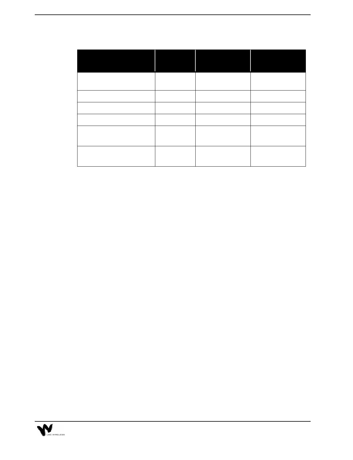
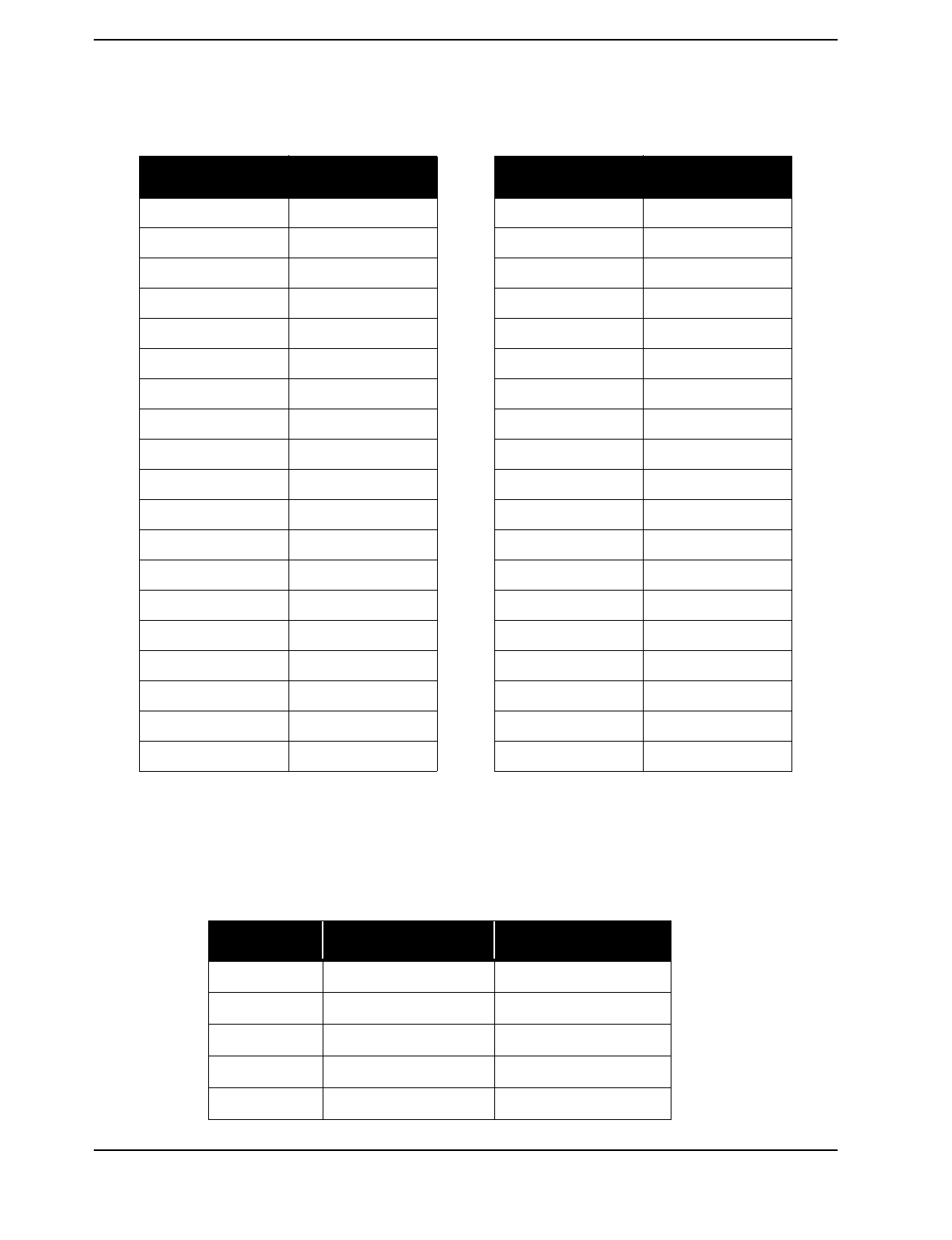
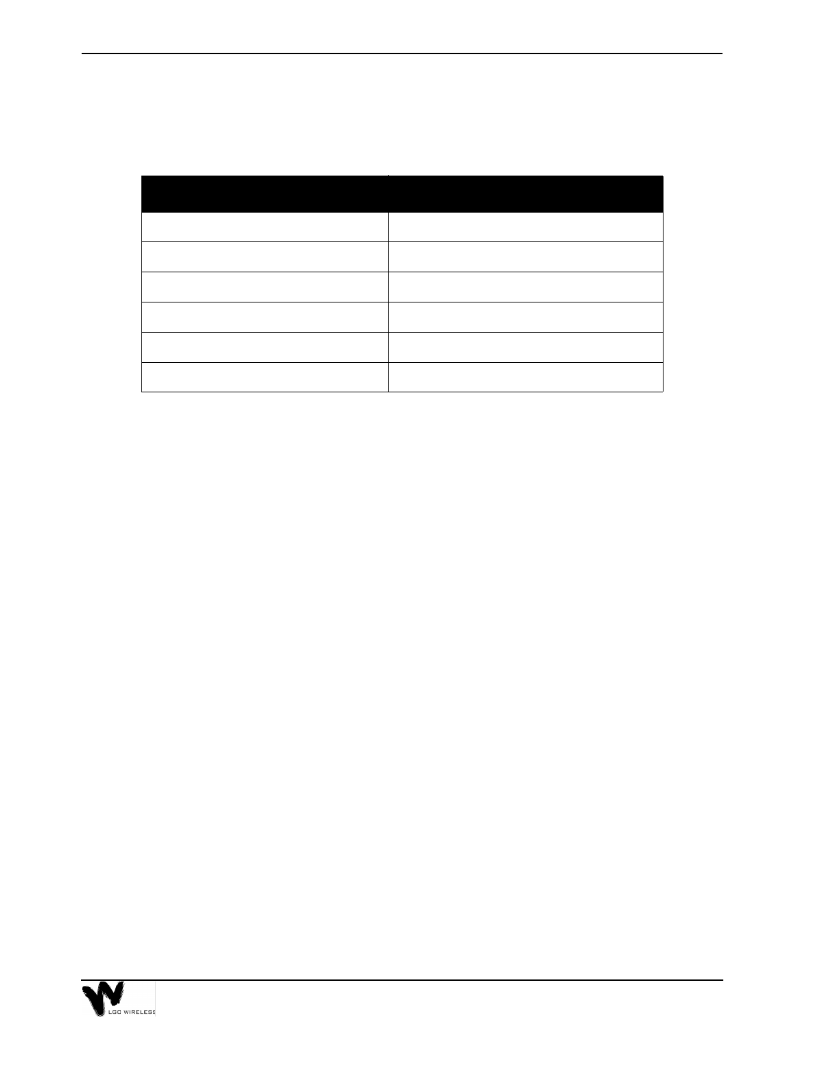
Project Management Estimated Timeline
RF Coverage Estimate for a Site
To provide adequate RF coverage within a facility, you need a median signal level
strong enough for good voice communications.
As a guideline, you can refer to the following tables for general coverage areas,
based on a design goal of 0 dBm output power per carrier, -85 dBm received signal
strength (independent of communications protocol), 5 dB fade margin and 3 dBi
antenna gain.
Description Details Time Interval
Detailed site walk-
through/RF survey Prepare installation information, including RF plan,
floor plan, equipment order form, and final design. 2 weeks
Order LGCell
equipment Get all standard parts and accessories required. 8 weeks
Select cabling
contractor Complete installation statement of work and provide
floor plan with equipment locations, list of cabling
runs, and other materials and connections. Get
cabling quotation after walk-through.
2 weeks
Order all other
equipment Get equipment from all vendors, including cables,
connectors, MBS, surge protectors, and so on.
Monitor order progress and shipment.
4 weeks
Install cable Monitor installation. 1-5 days
Install LGCell Review installation checklist and prepare all
materials. 1-3 days
Test installation and
RF coverage Be sure there are no blank areas. 1 hour per
RAU
Generate as-built
document Prepare site plan diagram and coverage performance. 1-5 days
3-5
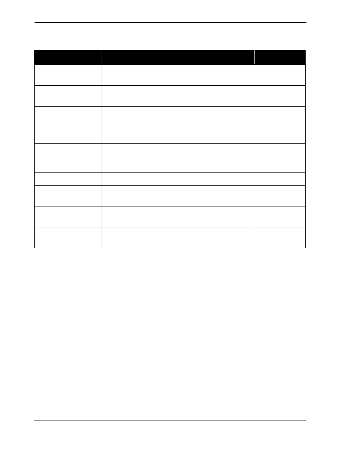
Antenna Coverage for 800/900 MHz Frequency Applications (0 dBm
per carrier, 5 dB fade margin, -85 dBm design goal and 3 dBi antenna
gain)
Antenna Coverage for 1800/1900 MHz Frequency Applications
Office Antenna Coverage for 800/900 MHz Frequency Applications
Facility PLS Coverage per Antenna (Square Feet)
Manufacturing 27.3 30,000
Hospital 28.8 15,000
Airport 27.3 30,000
Retail 27.7 25,000
Warehouse 27.3 30,000
Parking Garage 26.8 40,000
Facility PLS Coverage per Antenna (Square Feet)
Manufacturing 24.9 25,000
Hospital 26.5 10,000
Airport 24.9 25,000
Retail 25.2 20,000
Warehouse 24.9 25,000
Parking Garage 24.3 35,000
Facility PLS Coverage per Antenna (Square Feet)
Open - 80% cubicles/20% offices 27.7 25,000
80% - 50% cubicles/50% offices 28.2 20,000
10% - 20% cubicles/80% offices 28.8 15,000
3-6 LGCell Site Planning and Design
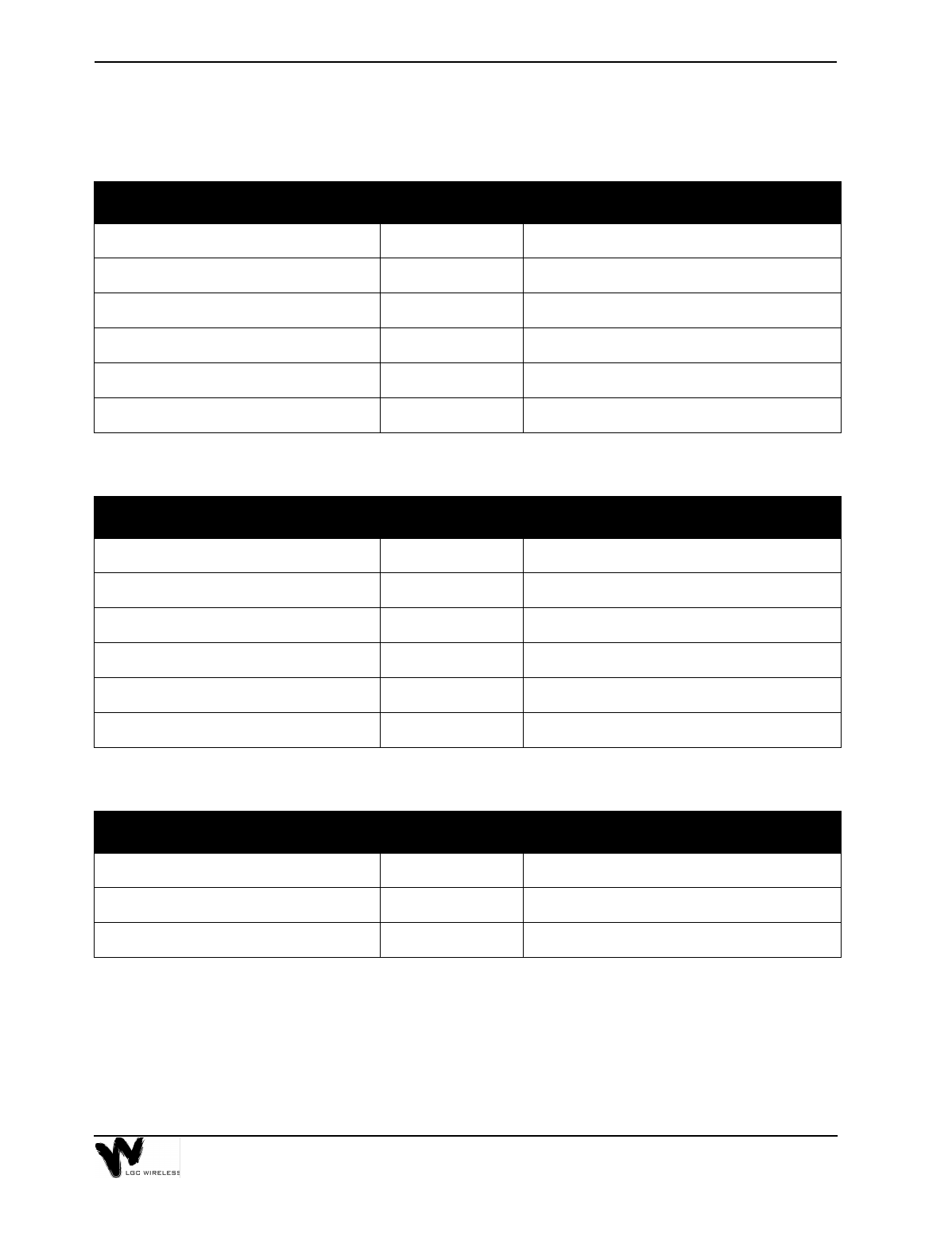
Office Antenna Coverage for 1800/1900 MHz Frequency Applications
The preceding tables show estimated clutter-defined path loss slope (PLS)
for different frequencies at various kinds of sites. If you change the design
goal or other parameters, these numbers will change based on the PLS.
If the design parameters (output power per carrier, design goal, antenna gain, and
fade margin) differ from those stated above, you can use the PLS value shown in
the preceding tables in the following formula to estimate the area of coverage per
antenna:
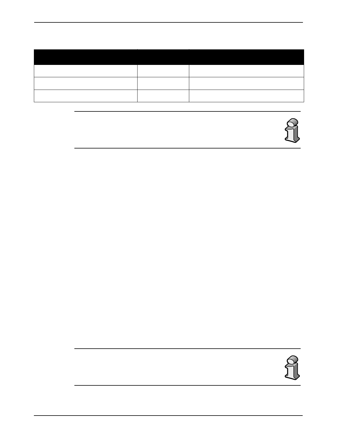
The PLS is a general path loss number which takes into account free space
loss and normal barriers to the RF signal. Severe obstructions such as
metal, cement walls, or elevator shafts are best accounted for by a physical
site survey.
Facility PLS Coverage per Antenna (Square Feet)
Open - 80% cubicles/20% offices 25.2 20,000
80% - 50% cubicles/50% offices 25.7 15,000
10% - 20% cubicles/80% offices 26.5 10,000
Path Loss Formulas
Path Loss (dB) = PLS * log 4πfD / c
Note: Path Loss Slope = PLS dB/decade for free space loss
D is the distance in meters
f is the frequency in MHz
c is the speed of light
Path Loss=Power per Carrier + Antenna Gain - Fade Margin - Design Goal (dBm)
To convert feet to meters:
Area = (D x 3.281)2 x π
D = [10(Path Loss / PLS)] x [c / (4πf)]
3-7
As a reference the following table gives estimates of the signal loss for some RF
barriers.
Average Signal Loss of Common Building Materials
RF Measurements and Site Survey
Before designing an LGCell system, one should go to the site and measure the loss
characteristics of the building. To determine the amount of coverage per antenna,
the best method is a test of RF propagation, which you can do on-site with a test
transmitter and field strength meter.
While at the site, one can use the following Site Survey Questionnaire to document
site specifics.
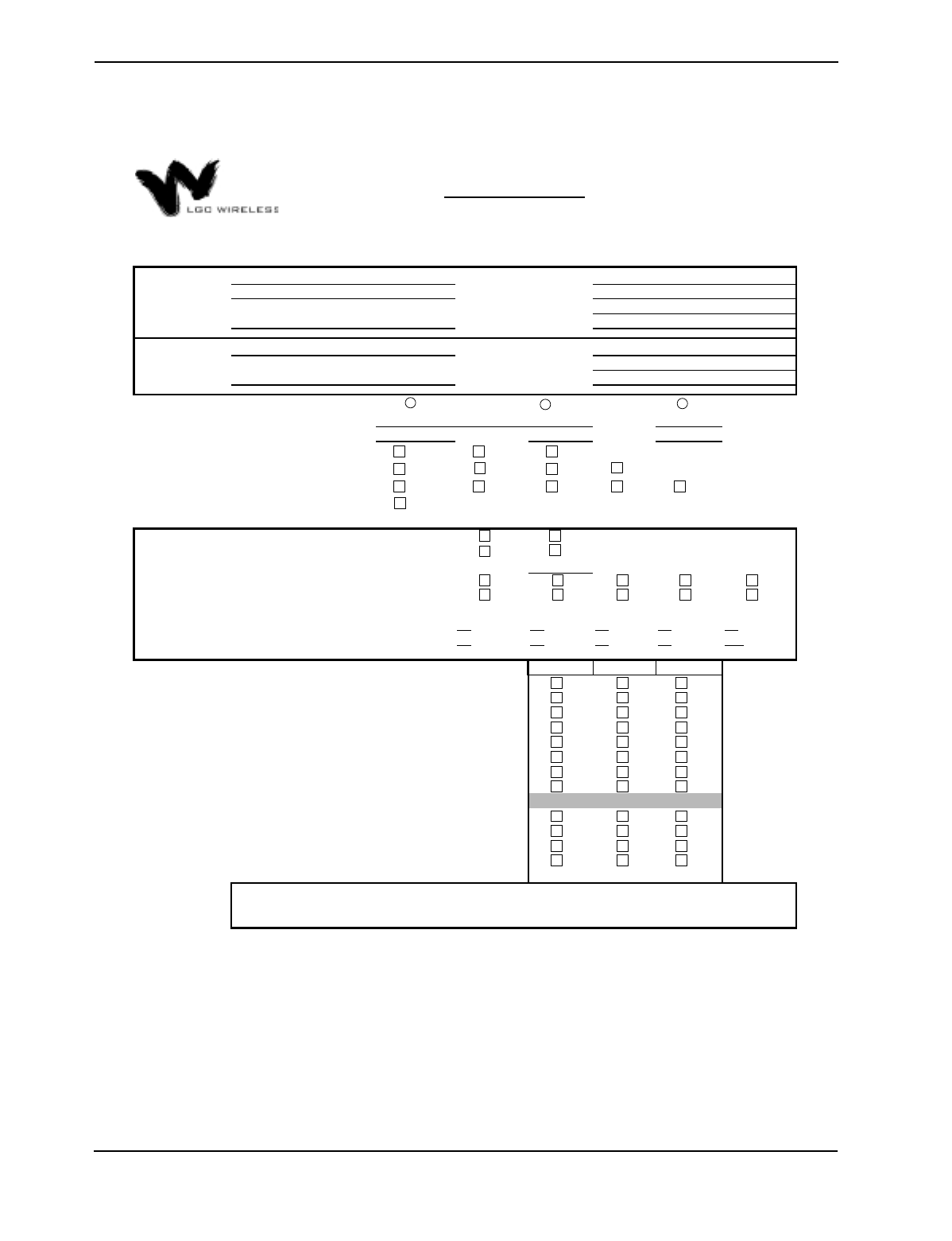
Site Survey Questionnaire
You can use the LGC Wireless Site Survey Questionnaire to help design your
LGCell system. A sample questionnaire follows. The following information is
needed when you walk a site:
Partition Type Loss @ 815 MHz
Metal wall 26 dB
Aluminum siding 20 dB
Concrete block wall 13 dB
Foil insulation 4 dB
Concrete floor 15 dB
Sheetrock 1.4 dB
3-8 LGCell Site Planning and Design
585 EAST BROKAW ROAD | SAN JOSE, CA 95112 | TEL 408.487.2400 | FAX 408.487.2410
End-User Contact:
# of Carriers:
BHCR: Erlangs/Sub:
1 = 2 = 3 = 4 = 5 =
6 = 7 = 8 = 9 = 10 =
Yes No Don't Know
Locations for Main & Expansion Hubs Available (closets):
Estimated Installation Start Date (Must Provide If Services are Needed):
Type of System Enhancement:
If BTS, what Manufacturer & Model #:
If BTS, what is the # of Subscribers:
What is the desired downlink power at mobile (dBm):
Are Exposed Antennas Tolerated Inside:
Are Floor Plans Available (Including Map Scale):
Site Survey Questionaire
Address:
Address:
Phone:
Company Name:
Frequency(ies):
Protocol(s):
E-Mail:
Add'l Comments:
(Special install
requirements, covered
areas
,
contacts
,
e
t
If so, which Services:
- Project Management:
Are 19" Equipment Racks Available:
Is AC Power available at the Main and Expansion Hubs:
Are Multimode Fiber Optic Cables Already Available:
- Site Survey:
- LGCell Equipment Install & Commissioning:
- CAT5, MMF, Coax & Antenna Installation:
Are CAT 5 UTP/STP Runs Already Available:
Are LGC Wireless Services Required:
Are Exposed Antennas Tolerated Outside:
Is Coverage Required Out Doors:
If Floor Plans are not available, how many Buildings are to be Covered:
How Many Floors per Building:
(Use the Add'l comments if needed)
Total Square Footage to Cover per Building:
(Use the Add'l comments if needed)
Project Name:
End-User:
Purchaser: Contact:
Phone:
E-Mail:
YES
YES NO
NO
Coverage (BDA) Capacity (BTS) Wireless Office
1 2 3 4 5
6 7 8 9 10
-75 -80 -85
800 900 1800 1900
GSM TDMA CDMA
DCS
AMPS iDEN
CONFIDENTIAL AND PROPRIETARY
Not to be distributed without prior written consent of LGC Wireless
Ver. 2.0