ADC Telecommunications DAS8M-4IDEN-W In-building distributed antenna system User Manual J bonnie john front cover eps
ADC Telecommunications Inc. In-building distributed antenna system J bonnie john front cover eps
Contents
Part 5 Users Manual
4-11
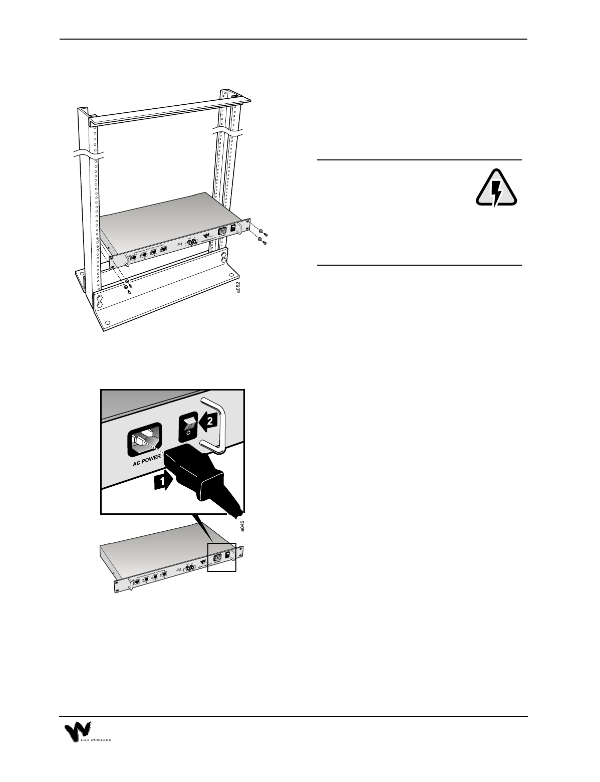
1 Mount the Expansion Hubs
Mount the Expansion Hubs onto the rack
in the assigned wiring closet location,
using four screws per hub.
For air circulation, be sure to
leave at least one inch (25 mm)
space between all hubs and
between any other equipment
in the rack. If mounting a hub on the
rack’s bottom shelf, also leave at least one
inch (25 mm) clearance from the bottom.
2 Connect Power and Power Up
Connect the AC power cord to the
Expansion Hub. Plug the power cord into
an outlet providing AC power (88-264
VAC). See 1 in graphic.
Power up the Expansion Hubs by flipping
the power switch from position 0 to
position 1. See 2 in graphic.
The POWER LED on the Expansion hub
should be green (lit).
4-12 LGCell Installation
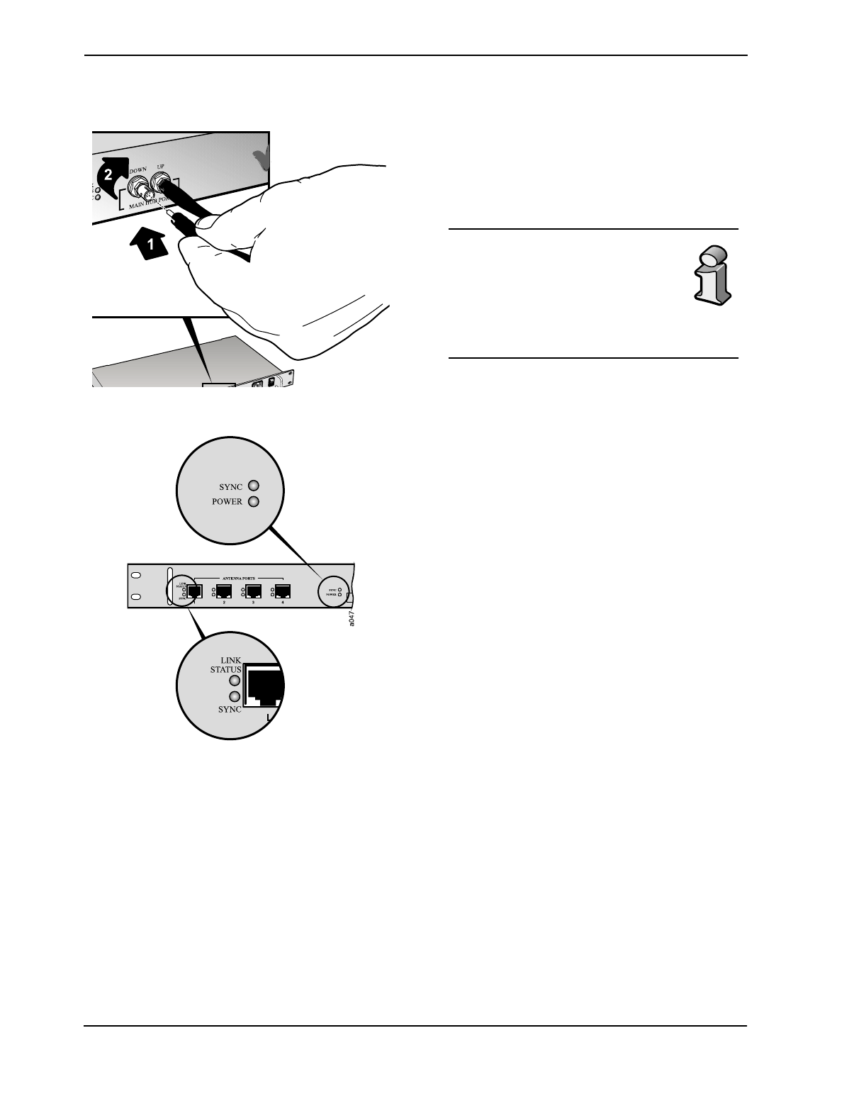
3 Connect the MMF cables
Connect all MMF cables from the Main
Hub to the Expansion Hubs. The SYNC
LED should be green.
For proper connection between
the Main Hub ports and the
Expansion Hub ports, refer to the
numbering or color coding you
recorded when installing the
Main Hub.
4 Check Expansion Hub LEDs
Connect all MMF cables from the Main
Hub to the Expansion Hubs.
The LINK STATUS and SYNC LEDs on each
Expansion Hub port should be red when
the UTP/STP cable is not yet connected to
the RAUs.
4-13
Remote Antenna Unit (RAU) Installation
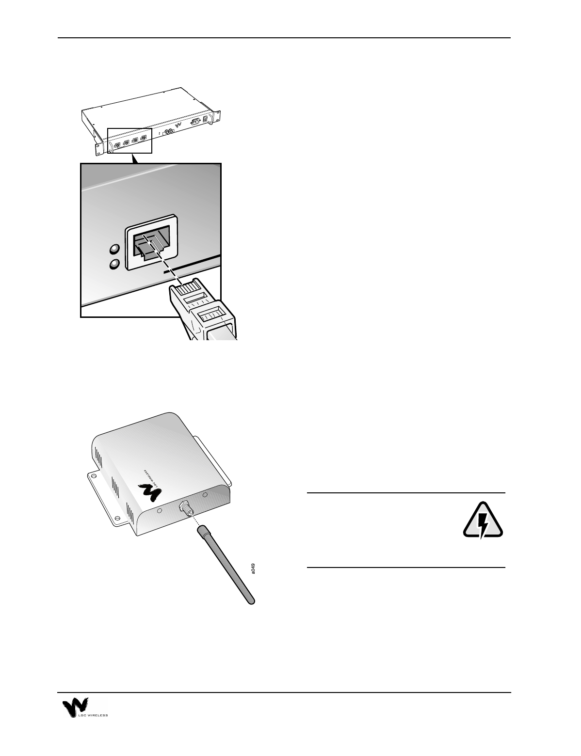
5 Connect UTP/STP cables from RAUs
Connect all UTP/STP cables coming from
the RAUs to any available RJ-45
connector on the Expansion Hub.
The Expansion Hub fiber port
LINK STATUS and SYNC LEDs should be
green or off.
The LINK STATUS and SYNC LEDs on each
Expansion Hub port should remain red
until the RAU is connected on the other
end.
1 Connect Antennas
Connect an accessory antenna to each
RAU SMA connector. (The illustration
shows the RAU with an optional Rubber
Duck antenna.)
When connecting to the SMA
connector on the antenna, DO
NOT over-tighten the
connector. Firmly hand-
tightening the connector is adequate.
TENNA PORTS
LGCell
™
E
DOWN
MAIN HUB PORTS
UP
SYNC
POWER
AC POWER
ANTENNA PORTS
LGC WIRELESS
LGCell
™
Expansion Hub
LINK
STATUS
SYNC
4-14 LGCell Installation
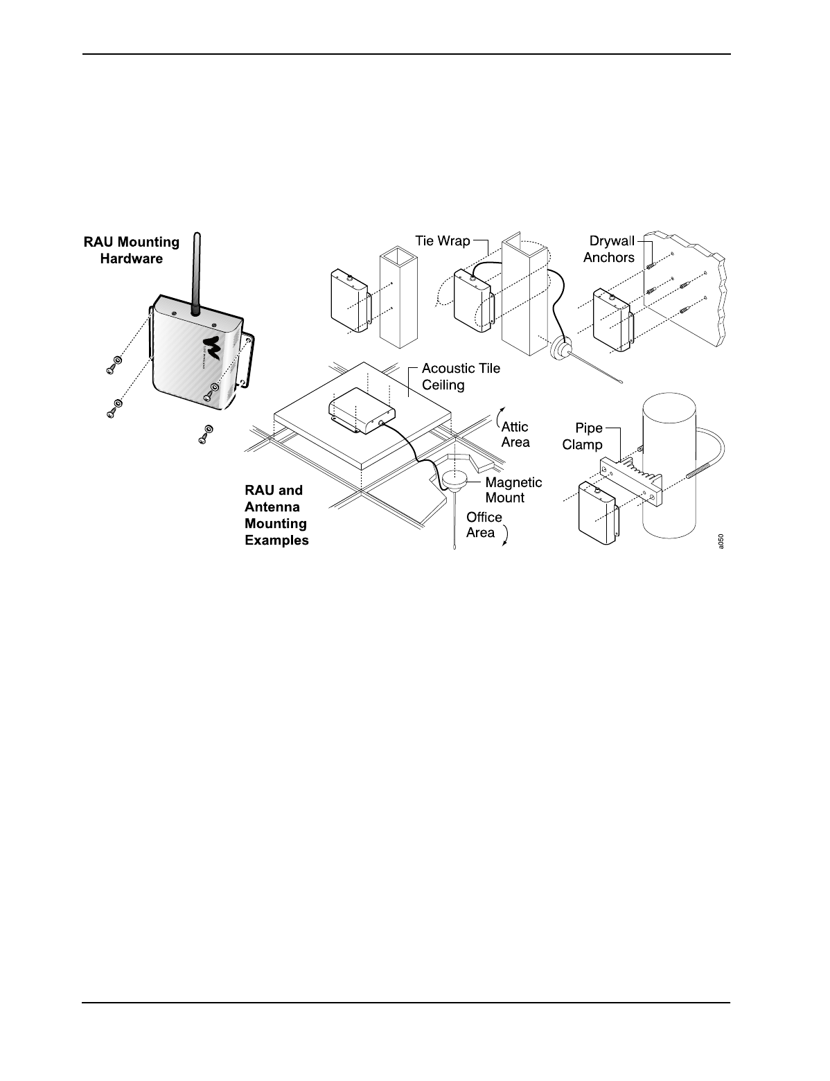
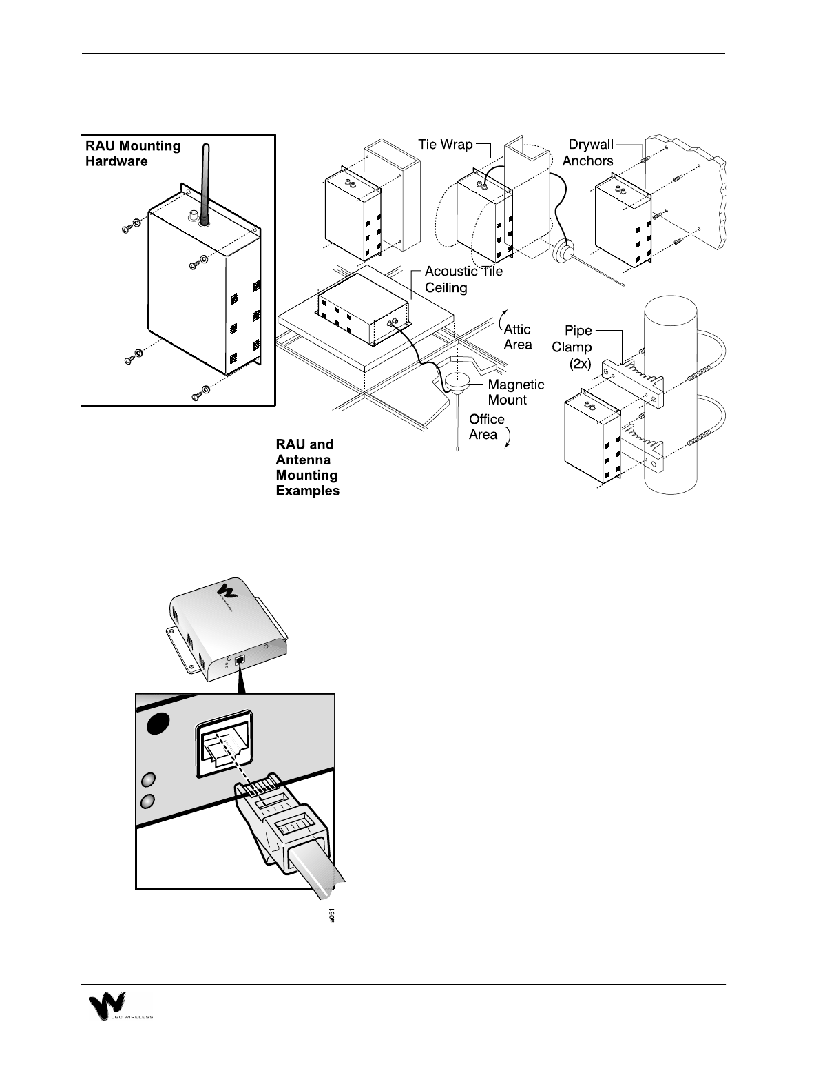
2 Mount RAUs and Antennas
Mount all RAUs in their assigned locations, using the enclosed screws. The
RAUs can mount above or below the ceiling, or to a wall.
For connecting and mounting an accessory directional antenna, refer to the
instructions shipped with that antenna.
4-15
The Dual Band RAU mounting is shown below.
3 Connect UTP/STP Cable
Connect the UTP/STP cable coming from
the Expansion Hub to the RJ-45 connector
on the RAU.
4-16 LGCell Installation
RF Cable Connection
Before connecting any cables to the Main Hub, be sure the RF power
level does not exceed the input rating for the Main Hub. (See
“LGCell System Specifications” on page 16 in Section 2, LGCell
Equipment.)
For coverage applications, LGC Wireless recommends that you insert a lightning
arrestor or surge protector between a roof-mounted antenna and the Main Hub. If
you use a repeater, insert the lightning arrestor or surge protector between the
repeater and roof-mounted antenna.
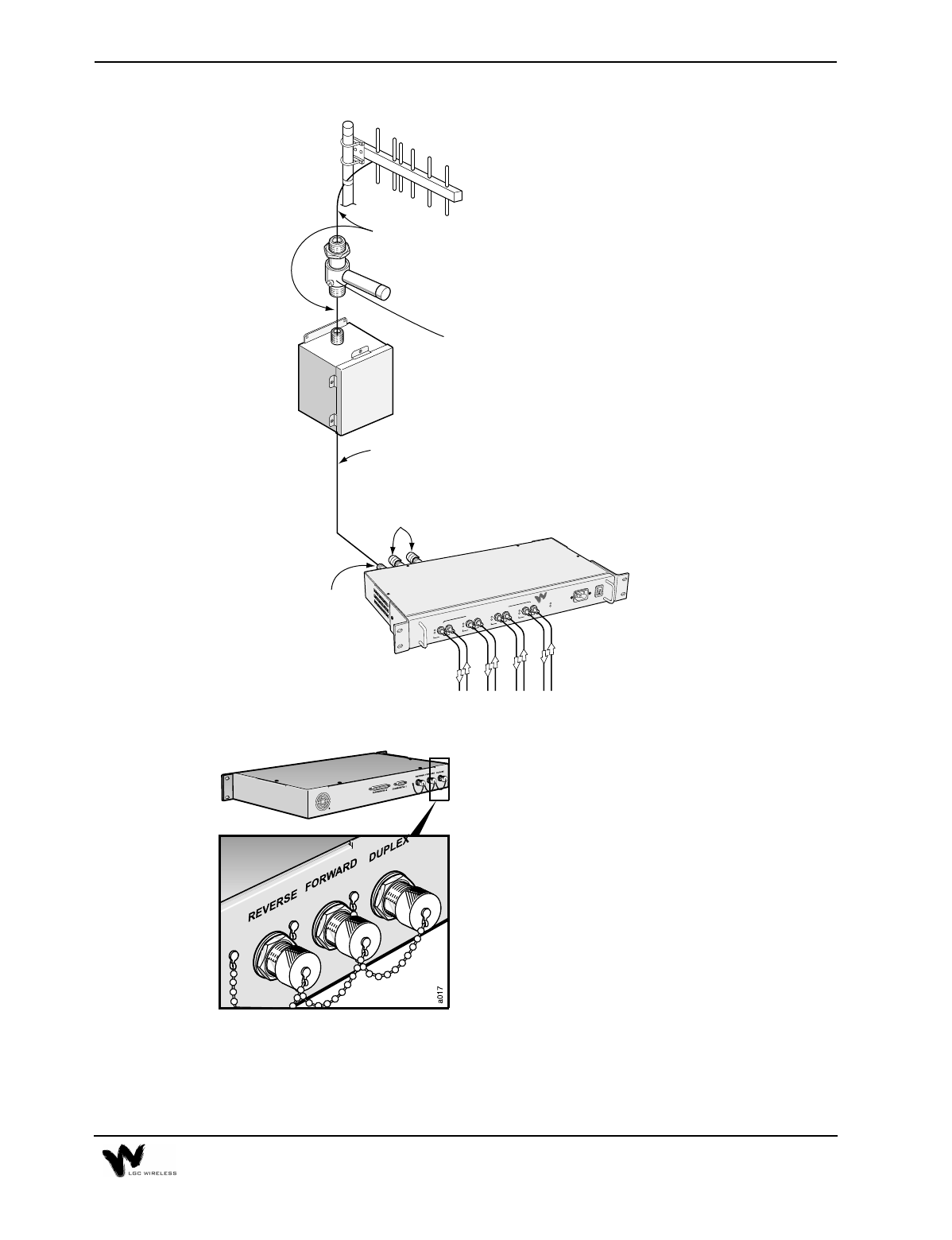
The following illustration shows how to connect the LGCell for coverage
applications, with a repeater.
For the Dual Band RAU, connect the
900 MHz Expansion Hub cable to the top
connector and the 1800 MHz cable to the
bottom connector.
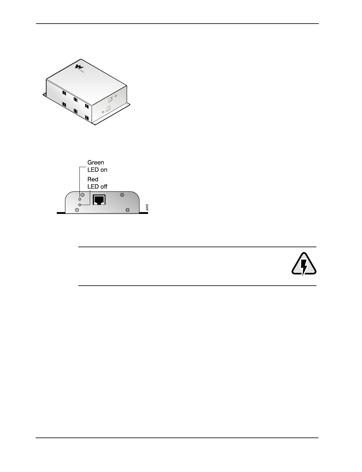
4 Check LEDs
The green POWER LED should be on and
the red ALARM LED should be off.
The green LED indicates that the RAU is
receiving power from the Expansion Hub
assigned to it.
4-17
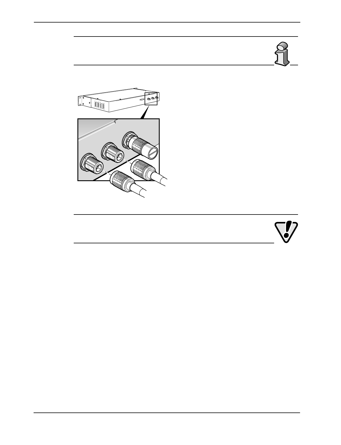
Duplex Connector
This N-type female connector is typically used
to connect the LGCell to a repeater, roof-
mounted antenna, or MBS, as shown on the
previous page.
Connect an N-type male RF coaxial cable to the
duplex N-type female connector (labeled
DUPLEX) on the Main Hub back panel. If an N-
type male connectorized RF cable is not
available, use an RF adaptor. Connect the other
end of the coaxial cable to the roof-mounted
antenna, MBS, or repeater.
a072
1234
DOWN
LINK
STATUS
SYNC
UP
SYNC
POWER
AC POWER
TO EXPANSION HUB PORTS
LGC WIRELESS
LGCell
™
Main Hub
DOWN
LINK
STATUS
SYNC
UP
DOWN
LINK
STATUS
SYNC
UP
DOWN
LINK
STATUS
SYNC
UP
Uplink (Reverse) and
Downlink (Forward) -
Main
Hub
N-Male to N-Male Coaxial Cables
N-Male to N-Male Coaxial Cables
Roof-Mounted Antenna
Surge Suppressor
Repeater
To Ground Connector
Duplex
Output
4-18 LGCell Installation
The duplex ports have a variable gain. Please see the table for system
gain under “Maximum Input RF Power per Carrier vs. Number of
Carriers” on page 17 in Section 2, LGCell Equipment.
Downlink (Forward) and Uplink (Reverse) Connectors
Connect an N-type male RF coaxial cable to
the downlink N-type female connector
(labeled FORWARD) and an N-type male RF
coaxial cable to the uplink N-type female
connector (labeled REVERSE) on the Main Hub
back panel.
Connect the other ends of the coaxial cable to
the MBS. For diagrams of connecting LGCell
to specific MBS equipment, see Section 5,
Connectivity.
For simplex MBSs, be sure the MBS downlink coaxial cable connector
plugs into the downlink connector, and the uplink coaxial cable
connector plugs into the uplink connector on the Main Hub.
Alarm Report Monitor
A separately orderable option for use with LGCell, the Alarm Report Monitor is an
alarm monitoring, reporting, and remote control system. Up to 255 remote-ARM
monitoring units can monitor up to 2,040 LGCell systems. Each remote-ARM unit
communicates with the ARM software through a dial-up modem connection, using
an external or internal modem. A database of these devices is set up in a PC, with a
unique address for each device.
The ARM supports multiple users and tracks responsibility through log-in and log-
out procedures, using four security levels to protect critical system functions. It
features a graphic color status display, remote system reset control, alarm history
and control logs, security code management, and journal printer and paging options.
For ARM installation instructions, see Appendix E – Alarm Report Monitor
(ARM2000).
a060
DUPLEX
FORWARD
REVERSE