ADC Telecommunications DAS8M-4IDEN-W In-building distributed antenna system User Manual J bonnie john front cover eps
ADC Telecommunications Inc. In-building distributed antenna system J bonnie john front cover eps
Contents
Part 3 Users Manual
5Connectivity
This section describes how to connect multiple LGCell systems and how to connect
specific microcellular base stations (MBSs) to the LGCell.
Please refer to the tables in Section 2, LGCell Equipment, for important
information on system gains and maximum RF power per carrier.
Contents
Connectivity
Connecting Multiple LGCell Systems. . . . . . . . . . . . . . . . . . . . . . . . . . . . . . . . . . 3
Connecting two LGCells . . . . . . . . . . . . . . . . . . . . . . . . . . . . . . . . . . . . . . . . . . . . 3
Connecting More Than Two LGCells . . . . . . . . . . . . . . . . . . . . . . . . . . . . . . . . . . 4
Connecting LGCell to Base Stations, Microcells, or Picocells . . . . . . . . . . . . . . . 4

5-2 Connectivity
5-3
Connecting Multiple LGCell Systems
Connecting multiple LGCell systems increases the total number of Remote
Antenna Units (RAUs). Multiple LGCells can be stacked to increase the total
number of RAUs through the use of power combiner/dividers.
LGC Wireless provides Integration Modules which may be used with the LGCell
to efficiently centralize additional radio capacity inside a facility. These Modules
provide the connection between the radios for the facility and the LGCell system.
Because the Integration Modules distribute all available radio capacity
automatically among all antennas within a cell, available capacity is dynamically
allocated throughout the entire coverage area, thus providing an improved grade of
service without the need to conduct ongoing traffic monitoring and analysis.
Specific installation information on all available Integration Modules may be found
in the Integration Module Installation and Reference Manual.
Connecting two LGCells
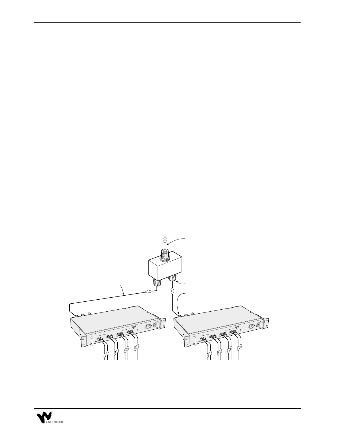
Connecting two LGCells increases the total number of RAUs from 16 to 32. A 2x1
or 2x2 hybrid power combiner/divider is required (see graphic below).
a009
1234
DOWN
LINK
STATUS
SYNC
UP
SYNC
POWER
AC POWER
TO EXPANSION HUB PORTS
LGC WIRELESS
LGCell
™
Main Hub
DOWN
LINK
STATUS
SYNC
UP
DOWN
LINK
STATUS
SYNC
UP
DOWN
LINK
STATUS
SYNC
UP
1234
DOWN
LINK
STATUS
SYNC
UP
SYNC
POWER
AC POWER
TO EXPANSION HUB PORTS
LGC WIRELESS
LGCell
™
Main Hub
DOWN
LINK
STATUS
SYNC
UP
DOWN
LINK
STATUS
SYNC
UP
DOWN
LINK
STATUS
SYNC
UP
Main Hubs
2 x 1 Power Combiner
N-Female Connectors
In Back of MH
N-Male to N-Male
Coaxial Jumper Cables (2)
N-Male to N-Male
Coaxial Jumper Cables
N-Female Connectors (3)
To Antenna on Roof
or MBS or Repeater
5-4 Connectivity
The following are procedures for connecting two LGCells. For Dual Band
installations, connect a power combiner/divider for each Main Hub band.
1 Connect Cables
2 Check Main Hub LEDs
After connecting the LGCells, check all Main Hub LEDs to ensure that the
system is operating properly.
Connecting More Than Two LGCells
Repeat this procedure to connect any number of LGCell systems. For three systems,
use a 3x1 power combiner/divider, and so on.
Connecting LGCell to Base Stations, Microcells, or
Picocells
One or more LGCell systems can connect with any base station, microcell, or
picocell. Before connecting an LGCell system to one of these, confirm the
following items:
•Connector type (LGCell uses N-type connectors)
•Power distribution (LGCell supports either duplex or simplex)
•Maximum power output (dBm) (Do not exceed the maximum input power into
the Main Hub. If the input power is too high, an attenuator might be required.)
For more information about connections to microcellular base stations or picocells,
including connections to multiple base stations, see the Integration Module
Installation and Reference Manual.
From LGCells to Hybrid Power
Combiner/Divider To Roof-Mounted Antenna, Repeater,
or MBS
Connect the DUPLEX, FORWARD, or
REVERSE connector of one of the Main
Hubs to an input/output port on the power
combiner/divider using an N-male to N-
male coaxial cable jumper.
Connect the combined port of the power
combiner/divider to a roof-mounted antenna,
repeater, or MBS using an N-male to N-male
coaxial cable jumper.
Connect the DUPLEX, FORWARD, or
REVERSE connector of the second Main
Hub to the second input/output port on the
power combiner/divider using an N-male to
N-male coaxial cable jumper.
6 Common Problems, Troubleshooting, and
Frequently Asked Questions
This section provides procedures for troubleshooting LGCell problems based on the
front panel diagnostic LEDs.
LGCell has no user-serviceable parts. Faulty or failed units are fully
replaceable through LGC Wireless. U.S. customers, please contact us at
1-800-530-9960. International customers, please contact us at
+1-408-487-2400.
Contents
Common Problems, Troubleshooting, and Frequently Asked Questions
Common Problems and Troubleshooting . . . . . . . . . . . . . . . . . . . . . . . . . . . . . . . 3
LED Indicator Description. . . . . . . . . . . . . . . . . . . . . . . . . . . . . . . . . . . . . . . . . . . 4
Troubleshooting Guidelines. . . . . . . . . . . . . . . . . . . . . . . . . . . . . . . . . . . . . . . . . . 6
Diagnostic Procedures . . . . . . . . . . . . . . . . . . . . . . . . . . . . . . . . . . . . . . . . . . . . . . 8
Frequently Asked Questions . . . . . . . . . . . . . . . . . . . . . . . . . . . . . . . . . . . . . . . . 13

6-2 Common Problems, Troubleshooting, and Frequently Asked Questions
6-3
Common Problems and Troubleshooting
The LGCell has three sources of potential problems:
•Malfunction of one or more LGCell component
•Faulty cabling/connector
•Antenna, base station, or repeater problem
By far, most problems discovered have to do with faulty cabling. All
CAT 5 cable should be tested to TIA/EIA 568-A specifications.
The diagnostic procedures are based on information in the Diagnostic Table on
page 9. The table lists all LEDs and indicates what to do under certain
circumstances. There is a blank table at the end of this section that you can copy and
use to record the LEDs while you troubleshoot an LGCell system.
After following the recommended procedures, if you cannot determine the cause of
a problem, call LGC Wireless customer help hotline:
1-800-530-9960
(International customers, please call +1-408-487-2400 for assistance.)
6-4 Common Problems, Troubleshooting, and Frequently Asked Questions
LED Indicator Description
The LGCell Main Hub, Expansion Hubs, and RAUs have front panel LEDs. The
LEDs provide diagnostic information and operational status of each unit. Together
they provide an efficient diagnostic display system, which help technicians find the
fault if there is a malfunction.
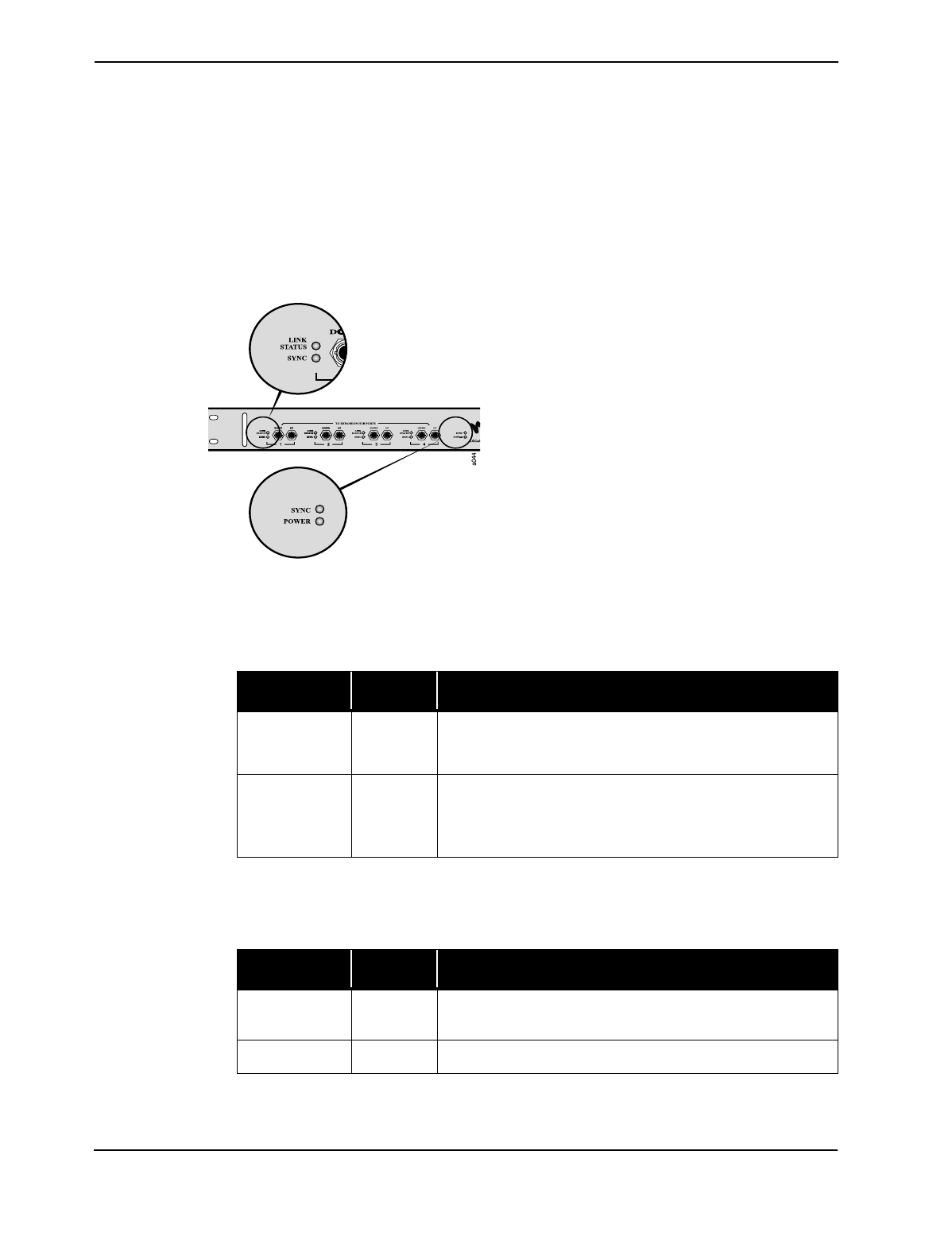
Main Hub LEDs
There are two sets of LEDs on the Main Hub
front panel:
•Main Hub MMF Ports
•Main Hub Functionality LEDs
•Main Hub MMF Ports LEDs
Provides status on each of the Main Hub’s four MMF ports.
•Main Hub Functionality LEDs
The LEDs provide diagnostic information on the Main Hub’s functionality.
LED Color Indication
LINK STATUS Green
Red
Indicates a good connection to Expansion Hub for that port.
Connection problem to Expansion Hub.
SYNC Green
Red
Indicates Expansion Hub and any RAUs connected to it are
operating properly.
Problem with Expansion Hub or one of the RAUs.
LED Color Indication
SYNC Green Indicates Main Hub is correctly producing the
synchronization signal.
POWER Green Turns green when Main Hub has power.
6-5
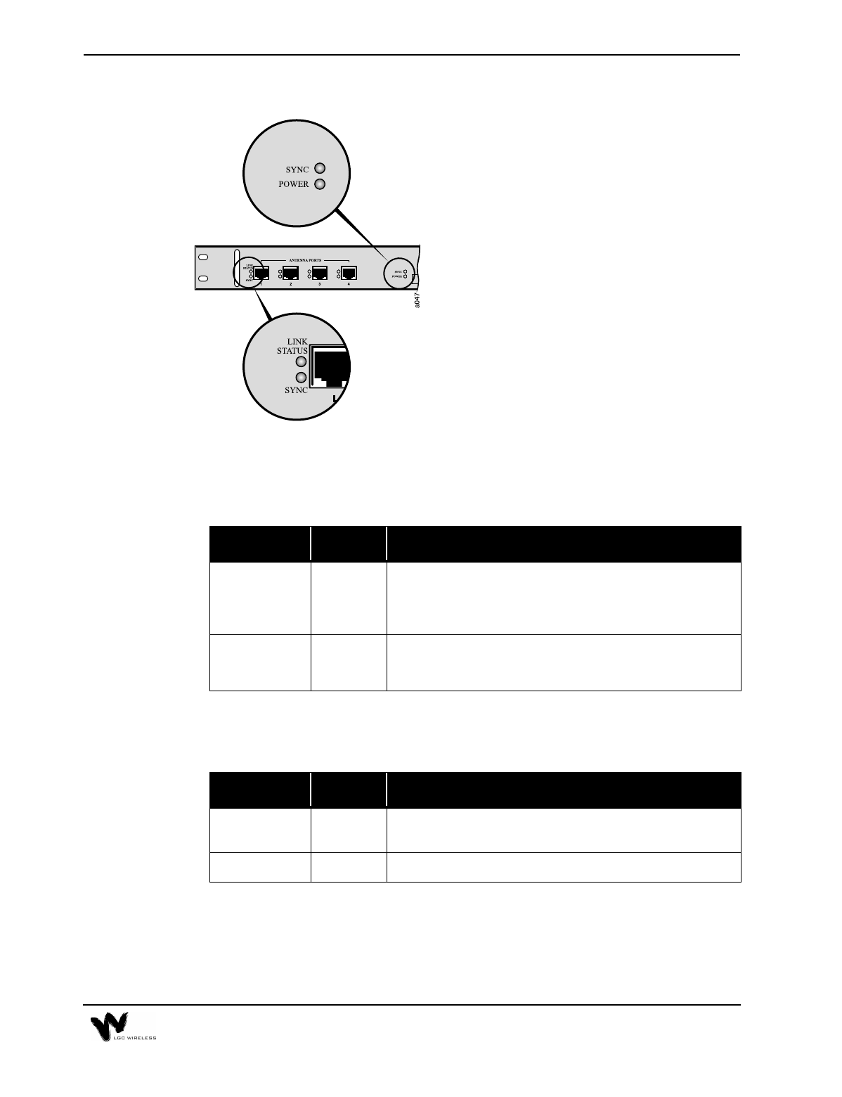
Expansion Hub LEDs
There are two sets of LEDs on the front panel
• Expansion Hub
UTP/STP Ports
• Expansion Hub Functionality
• UTP/STP Ports LEDs
Provides status on each of the Expansion Hub’s four UTP/STP ports.
•Expansion Hub Functionality LEDs
Provides diagnostic information on the Expansion Hub’s functionality.
LED Color Indication
LINK STATUS Green
Red
Indicates good connection to the RAU.
Connection problem between Expansion Hub and the RAU
plugged into that port.
SYNC Green
Red
Indicates RAU connected to it is operating properly.
Problem with the RAU plugged into that port.
LED Color Indication
SYNC Green Indicates Expansion Hub is receiving the synchronization
signal from Main Hub.
POWER Green Turns green when Expansion Hub has power.
6-6 Common Problems, Troubleshooting, and Frequently Asked Questions
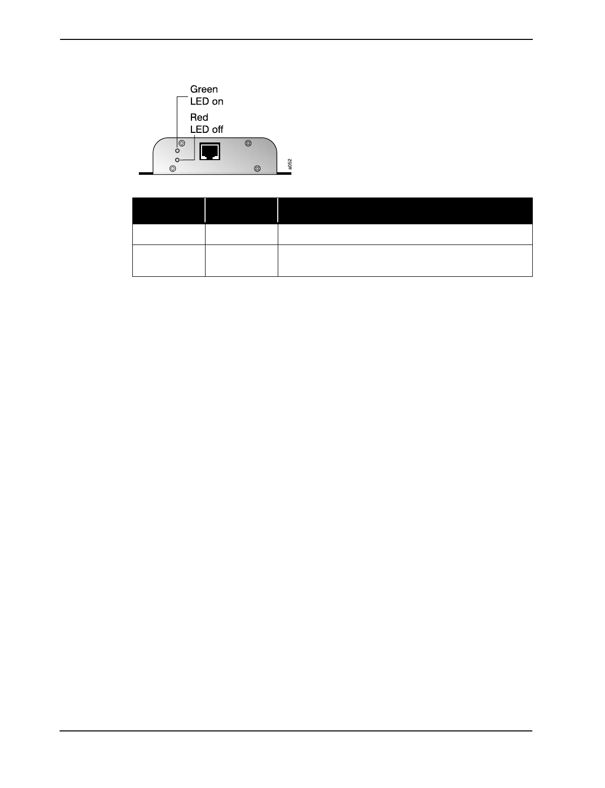
RAU LEDs
RAUs have two LEDs:
•Sync
•Power
Troubleshooting Guidelines
The LGCell Main Hub, Expansion Hub, and RAUs have front-panel indicator
LEDs that provide diagnostic information and the operational status of each unit.
Together they provide an efficient diagnostic display system for maintenance and
fault location if a malfunction ever exists. The troubleshooting procedures in this
section are based on the front panel diagnostic LEDs.
The following table contains supplementary troubleshooting information that the
diagnostic LEDs do not cover. Please check the table for a possible cause of a
problem. Some simple checks or a minor adjustment might eliminate the problem
and restore proper operation.
LED Color Indication
SYNC Red Antenna lost sync and has shut down RF power.
POWER Green Antenna is plugged in and the connected Expansion Hub is
on.
6-7
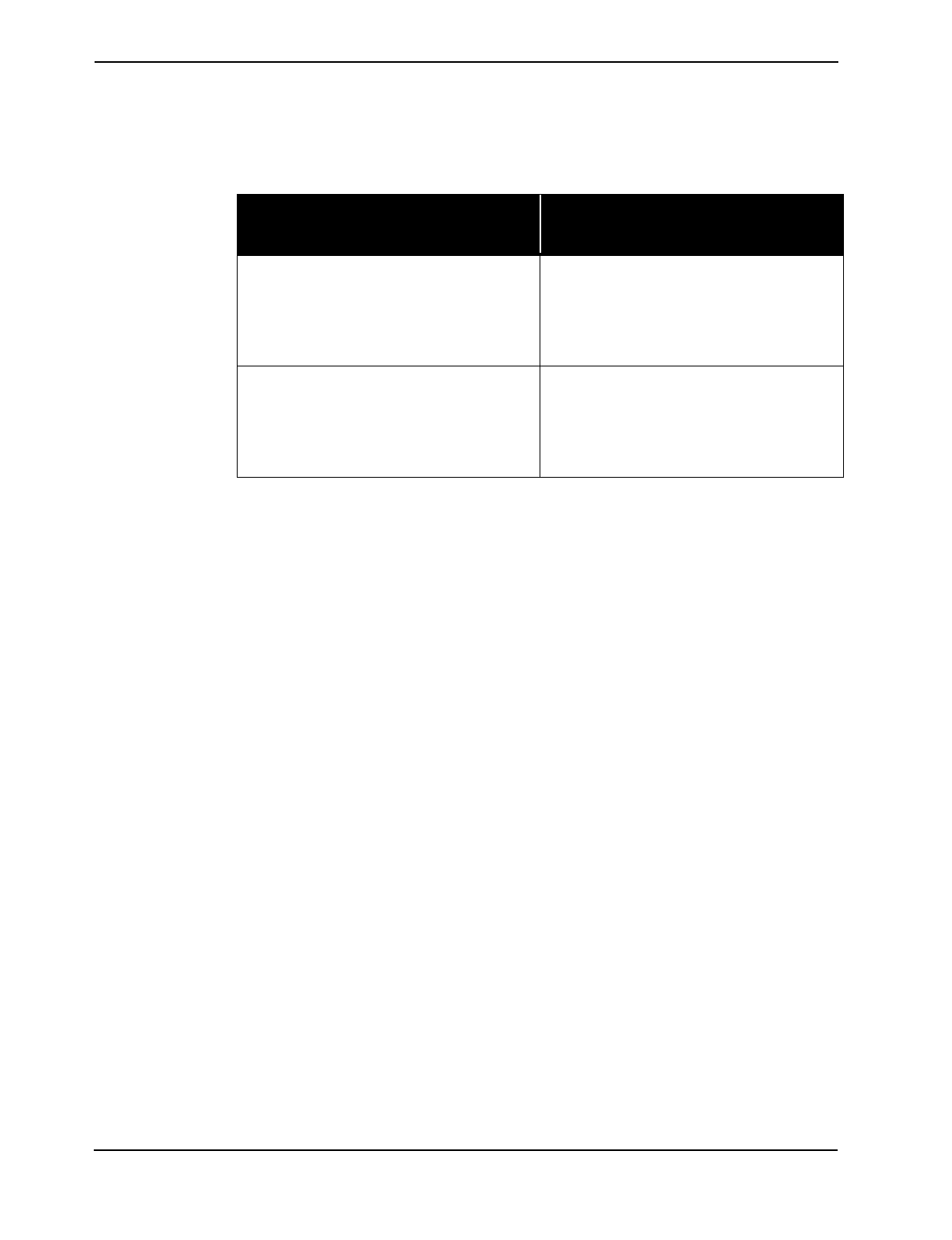
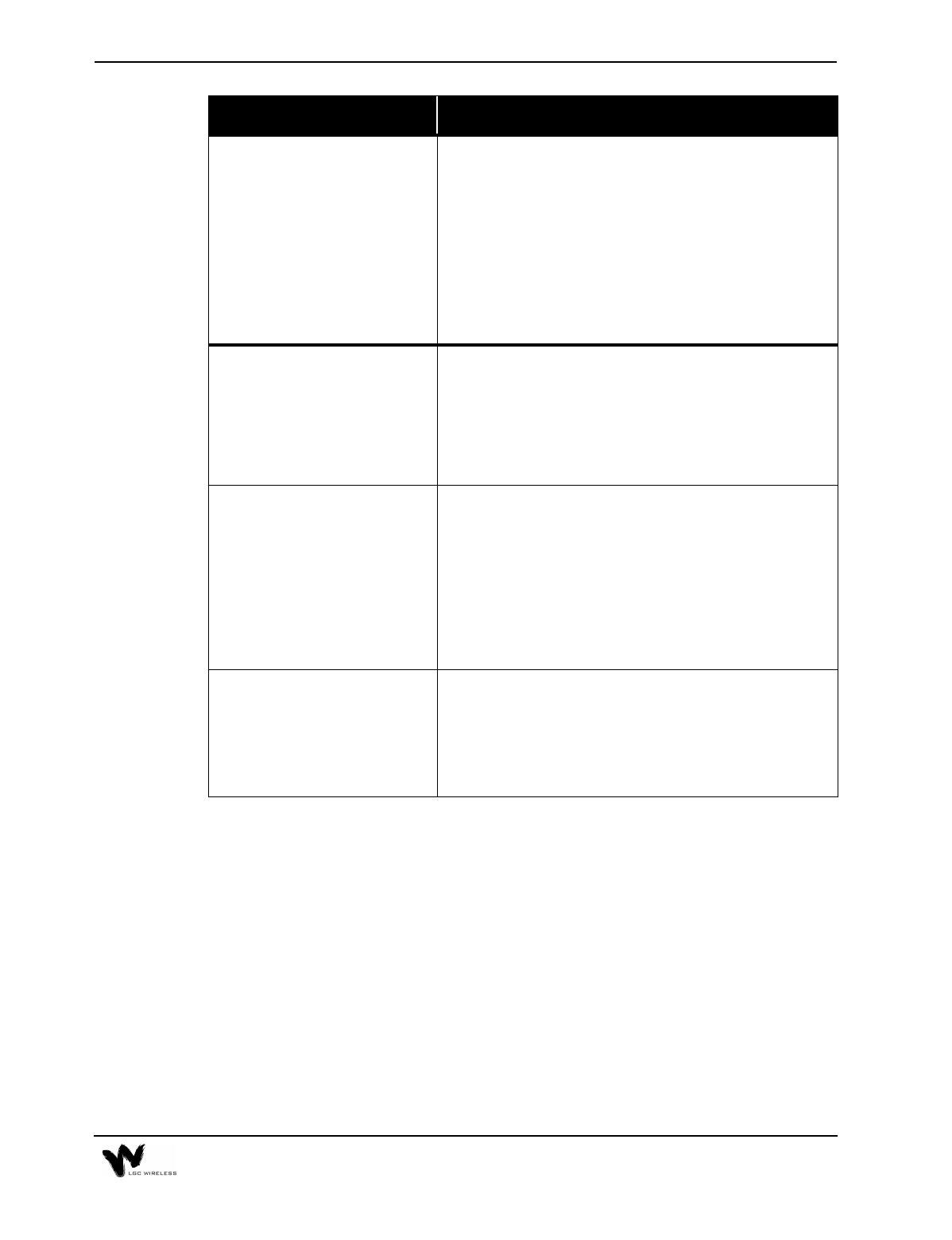
Problem/Symptoms Check
No downlink signal output when
all diagnostic LEDs are green. Make sure that there is a reasonable amount of power at the
input of the Main Hub. Measure the output power of the
coaxial cable using a power meter.
The LGCell is intended for a different frequency band.
Verify that your system corresponds to the desired
frequency spectrum (for example, 800 MHz, 1800 MHz, or
1900 MHz). Check the part number of each unit.
The LGCell is factory set for different bands of operation.
Please be sure you have the proper band.
The system gain is lower than
specification. The optical fiber connector is dirty. Clean the fiber ST-
connector, using the manufacturer’s recommended cleaning
procedure.
There are two types of Multi-Mode Fiber (MMF), 62.5/
125 µm and 50/125 µm. Make sure the vertical run MMF is
the 62.5/125 µm type of fiber.
Remote Antenna Unit (RAU)
power LED (green LED) stays
off after you plug in the twisted
pair cable.
The Expansion Hub provides power to the RAU. Make sure
the Expansion Hub is on.
Make sure that the twisted-pair (TP) cable wiring conforms
to the TIA/EIA 568-A standard. (For information about the
standard, refer to Appendix B – TIA/EIA 568-A
Cabling Standard.) Use a standard local area network
(LAN) cable tester to perform this test. Possible errors are
wrong wiring and/or cable length.
The LGCell performance is
intermittent when you use it for
the CDMA application.
The uplink and downlink gain is not balanced. A CDMA
system performs active power control between the base
station and the mobile unit. It is important to maintain a
balanced link from the base station ports to the RAU ports
(equal uplink and downlink gain) to optimize the
performance of the LGCell.

6-8 Common Problems, Troubleshooting, and Frequently Asked Questions
Diagnostic Procedures
Use the following table when diagnosing system problems. While troubleshooting,
you can copy the blank table on page 12 and use it to record the LED colors on the
Main Hub, the particular Expansion Hub indicating a fault, and the RAUs
connected to it. This is necessary because the Main Hub, Expansion Hubs and
RAUs might be geographically distributed.
To determine where the fault might be
1Go to the Main Hub and record the LEDs. The Main Hub indicates which
Expansion Hub may be faulty by lighting one of its port LEDs red.
2Go to the Expansion Hub attached to the port that has a red LED.
3Record that Expansion Hub’s LEDs. The Expansion Hub indicates which
RAU(s) may be faulty by lighting its antenna LED red.
4Go to the RAU(s) connected to the Expansion Hub port indicating a fault.
Record the error.
5Compare your filled in table to the Diagnostic Table below and begin
troubleshooting according to the notes indicated for your situation.
6-9
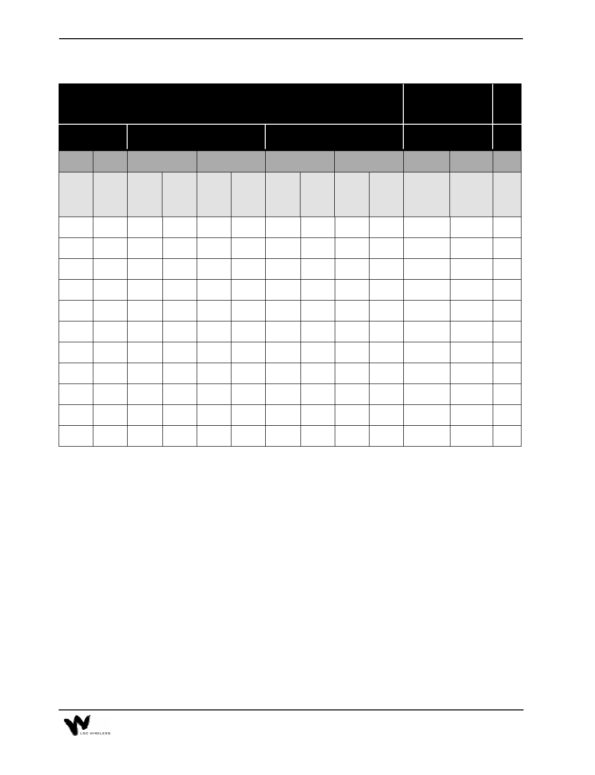
Diagnostic Table
Major and Error Latch contacts indicate an alarm when the contacts go from a short to open state.
* Major Alarm contact will momentarily open for 100 milliseconds.
The following numbers correspond to the “See Note” column of the Diagnostic
Table above.
1System is functioning properly.
2The Expansion Hub is off.
Make sure the power cord is connected to a live AC power jack and that the
Expansion Hub power switch is in the 1 position.
3Power is being delivered to the RAU but it is not turning on.
•Check that the UTP/STP cable has been properly crimped and passes a
standard CAT 5 compliance test.
•If that is not the problem, replace RAU.
Visual Alarm LEDs Remote Alarm
Contacts See
Note
RAU Expansion Hub Main Hub DB-9 Connector
PORT LEDS HUB LEDS PORT LEDS HUB LEDS
POWER SYNC LINK
STATUS
SYNC SYNC POWER LINK
STATUS
SYNC SYNC POWER MAJOR
ALARM
CONTACT
ERROR
LATCH
CONTACT
Green Green Green Green Green Green Green Green Green Green Short Short 1
Off Off Off Off Off Off Red Red Green Green Open Open 2
Off Off Green Red Green Green Green Red Green Green Open* Open 3
Off Off Red Red Green Green Green Red Green Green Open* Open 4
Green Red Green Red Green Green Green Red Green Green Open Open 5
Green Red Green Red Off Green Green Red Green Green Open Open 6
Green Red Green Red Red Green Red Red Green Green Open Open 7
Green Red Green Red Off Green Off Off Off Off Open Open 8
Green Red Green Red Red Green Green Red Red Green Open Open 9
Green Off Green Green Green Green Red Red Green Green Open Open 10
Off Off Red Red Green Green Green Red Green Green Open* Open 11

6-10 Common Problems, Troubleshooting, and Frequently Asked Questions
4Power is not being delivered to the RAU.
•Switch the UTP cable to a different Expansion Hub port to see if the same
problem occurs.
If the LEDs on the new port are both green, there is a problem with the
Expansion Hub.
If the problem persists, there is a problem with either the RAU or the UTP/
STP cable.
•Check that the UTP/STP cable has been properly crimped and passes a
standard TIA/EIA 568-A CAT 5 compliance test.
If the cable passes the CAT 5 test, replace the RAU.
5RAU has lost synchronization.
•Make sure that the UTP/STP passes CAT 5 testing.
•If the cable is OK, replace the RAU.
6The Expansion Hub is not properly receiving the synchronization signal from
the Main Hub.
•The MMF cable connection might not be good or if system was working,
the MMF downlink cable is pulled out or cut. Switch MMF cables.
•If the problem persists, switch to a different Main Hub port. If this solves
the problem, the Main Hub port is malfunctioning.
•If the problem persists, there is an Expansion Hub problem.
•If switching MMF cables is not practical, switch the uplink and downlink
pairs. (A connection error may have been made when connecting the Main
Hub UP port to the Expansion Hub UP port, and similarly for the DOWN
ports.)
•If the Expansion Hub SYNC LED turns green, one of the MMF cables was
bad or the connection between the Main Hub and Expansion Hub was done
incorrectly. If both are bad, this test will not help. Switch to a different
Main Hub port.
7The Expansion Hub is not properly receiving the synchronization signal from
the Main Hub.
Too much loss on downlink MMF. Might be due to MMF pairs not attached to
the proper connector.
•Check that the “down” cable end is in the DOWN port connector on both the
Main Hub and on the Expansion Hub. Same for the “up” cable end and
connectors for the UP port.
•If the problem persists, check the integrity of MMF cable using an Optical
Time Domain Reflectometer. If the fiber is faulty, replace it.
•If the MMF cable is OK, try using a different Main Hub port.

6-11
•If the problem persists, replace the Main Hub.
•If the problem persists, replace the Expansion Hub.
8The Main Hub is off.
Make sure the power cord is connected to a live AC power jack and that the
Main Hub power switch is in the 1 position.
9Main Hub is not properly generating the synchronization signal.
Turn off the Main Hub and turn it back on. If the sync LED stays off, the Main
Hub might require replacement.
10 The Expansion Hub is not properly sending the synchronization signal to the
Main Hub.
The MMF cable connection might not be good, or if the system was working,
the MMF uplink cable is pulled out or cut.
11 The RAU is off.
•Check that the UTP/STP cable is operating properly.
•If the system was working, the RJ 45 cable is pulled out or cut.
6-12 Common Problems, Troubleshooting, and Frequently Asked Questions
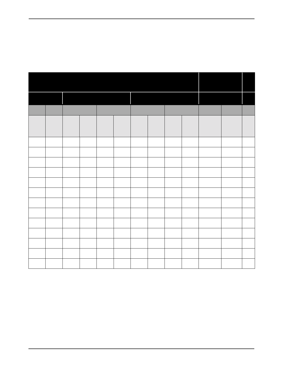
Diagnostic Table
Use the following blank table to record LEDs as you troubleshoot
Visual Alarm LEDs Remote Alarm
Contacts See
Note
RAU Expansion Hub Main Hub DB-9 Connector
PORT LEDS HUB LEDS PORT LEDS HUB LEDS
POWER SYNC LINK
STATUS
SYNC SYNC POWER LINK
STATUS
SYNC SYNC POWER MAJOR
ALARM
CONTACTS
ERROR
LATCH
CONTACT

6-13
Frequently Asked Questions
The following list provides answers to some frequently asked questions about
LGCell:
1What is the LGCell Distributed Antenna System?
The LGCell Distributed Antenna System (DAS) contains multiple low-power
radiating elements that are deployed around indoor facilities to improve
coverage and capacity. The unique, patented architecture of the LGCell DAS
provides an inexpensive solution to the cellular and PCS provider for coverage/
capacity upgrades and private microcell applications.
2What is twisted pair cable? Will it pick up spurious emissions?
Twisted pair (TP) cable is the standard cable that you find at the back of your
computer for the network hookup. TP cable is the most ubiquitious cable in any
office building. Furthermore, TP cable is inexpensive and easy to install. The
twisting nature of the cable creates a transmission line for efficient signal
transfer and rejection of spurious emissions The LGCell uses a state-of-the-art
common-mode rejection device that reduces pickup of spurious emissions on a
TP cable by a factor of 10,000.
3Can a single LGCell simultaneously support multiple access standards (such
as 800 AMPS/TDMA?
Yes. The LGCell is a frequency selective product. The LGCell system is
transparent to the protocol that the base station and mobile unit use. You can
view the entire system with all the cables together as a frequency selective
repeater with a specified gain.
4What is the bandwidth of the LGCell?
LGCell selects from the RF bandwith, which can help prevent amplification of
an unwanted signal, such as a competitor’s signal. Refer to the data
specifications for the RF bandwith of the system. Another interpretation of
bandwidth is the amount of data that the LGCell system can transmit. The
microcellular or macrocellular base station to which the LGCell is connected
limits the bandwith or capacity of the LGCell, which is a transparent system.
Total, composite output power and spurious emissions are the only constraints
that limit the amount of channels that an RAU can radiate. Furthermore, the
LGCell system shall not limit the data rate of the modulation transmitted
through the system.
5Can the LGCell support multiband operation?
The LGCell provides a wide variety of single-band products, including the U.S.
800 MHz, European GSM 900, DCS 1800, Korean PCS 1800, U.S. PCS 1900
systems, and iDEN. You can use these systems together to provide multiband
services. In addition, LGCell has a Dual Band 900/1800 system available.

6-14 Common Problems, Troubleshooting, and Frequently Asked Questions
6Can the LGCell system share the same UTP Category 5 Cable with the
Ethernet network?
No. The LGCell system can use the existing unused cabling inside the building;
however, you cannot use the same cable to connect an RAU and a computer.
7What is the minimum power input to the Main Hub?
The coverage area of an RAU is directly related to the input down link power
at the Main Hub. Therefore, an input power that generates an output power of
0dBm per channel optimizes the coverage area of an RAU.
8What is the minimum detectable power of an RAU?
The minimum detectable power of system with 1 RAU is -114 dBm in a 30 kHz
bandwidth, -106 dBm in a 200 kHz bandwidth, and -98 dBm in a 1.25 MHz
bandwidth, without taking into account the processing gain of different access
standards.
9What is the difference between connecting the LGCell to a roof-mounted
antenna and to a microcellular base station?
Connecting the LGCell to a roof-mounted antenna increases the coverage of the
indoor environment. Connecting the LGCell to a microcellular base station
improves both the coverage and the capacity in the building and might also
provide a private wireless office application for the customer.
10 Does each Main Hub require a separate coaxial feed to the base station?
A typical RF input power per channel to the Main Hub is 0 dBm. This provides
a lot of margin (link budget margin) for interfacing with antennas through a
base station that typically has an output power of 20 dBm. Therefore, a power
combiner/splitter might be installed between the MH and the base station. This
enables one base station to connect to multiple Main Hubs. For details, refer to
Section 2, LGCell Equipment.