ADC Telecommunications DLC1902B Digivance® LRCS 1900 MHz, 20-Watt LPA User Manual 75158
ADC Telecommunications Inc Digivance® LRCS 1900 MHz, 20-Watt LPA 75158
Contents
User manual 2

ADCP-75-158 • Issue 1 • July 2003 • Section 2: Description
Page 2-10
© 2003, ADC Telecommunications, Inc.
3.6 Antenna Cable Connection
An N-type female connector is provided on the exterior bottom side of the RU cabinet for
connecting the antenna coaxial cable. The exterior N-type connector is on the surge side of a
lightning protector that is mounted within the enclosure. On the inside of the enclosure, the
protected side of the lightning protector is also equipped with an N-type female connector. A
coaxial jumper cable (included with the enclosure) is used for connecting the protected side of
the lightning protector to the ANTENNA port on the STM.
3.7 AC Power Wiring and Grounding
The RU outdoor cabinet is equipped with a stub cable for the AC power connections. The AC
power cable provides three wire leads (Load, Neutral, and Ground) that must be connected to a
120 or 240 VAC power source. The AC power cable exits the cabinet though a 3/4-inch NPT
threaded hole located on the bottom of the cabinet. The threaded hole accepts a standard 3/4-
inch AC conduit fitting. A 3/4-inch to 1/2-inch reducer is also included if 1/2-inch conduit is
preferred over 3/4-inch conduit.
From the exit point in the bottom of the cabinet, the AC power cable must be routed through
conduit to an external AC junction box (not provided) where it can be connected to the AC
power wiring. The junction box should be located within two feet of the cabinet and should be
equipped with a 120 VAC GFCI outlet for powering test equipment and/or power tools. If AC
power spikes are likely to occur, the junction box should also include a surge protector to
protect the equipment from damage.
Three wire nuts are included with the cabinet for completing the AC power wiring connections.
The junction box wiring should be connected to the AC power source through a 20 Amp breaker
box (not provided). All AC power wiring should be run within conduit. A grounding lug is
provided on the underside of the enclosure for connecting a separate grounding wire directly to
the cabinet.
3.8 Ventilation
Vent openings are provided in the bottom of the RU cabinet to permit air exchange for cooling.
Air enters the cabinet through an opening in the front/bottom side of the cabinet A Filter
removes dirt particles so that only clean air enters the enclosure. Both the STM and LPA have
cooling fans. The STM has a rear mounted fan that pulls air through the module and exhausts it
toward the rear of the enclosure. The LPA has a fan on the front that draws air into the module
and exhausts it toward the rear of the enclosure. The heated air exits through an opening in the
rear/bottom side of the enclosure.
3.9 User Interface
The RU cabinet user interface consists of the various connectors, fittings, mounting slots, and
switches that are provided on both the interior and exterior of the enclosure. The user interface
points are indicated in Figure 2-4 and described in Table 2-2.
ADCP-75-158 • Issue 1 • July 2003 • Section 2: Description
Page 2-11
© 2003, ADC Telecommunications, Inc.
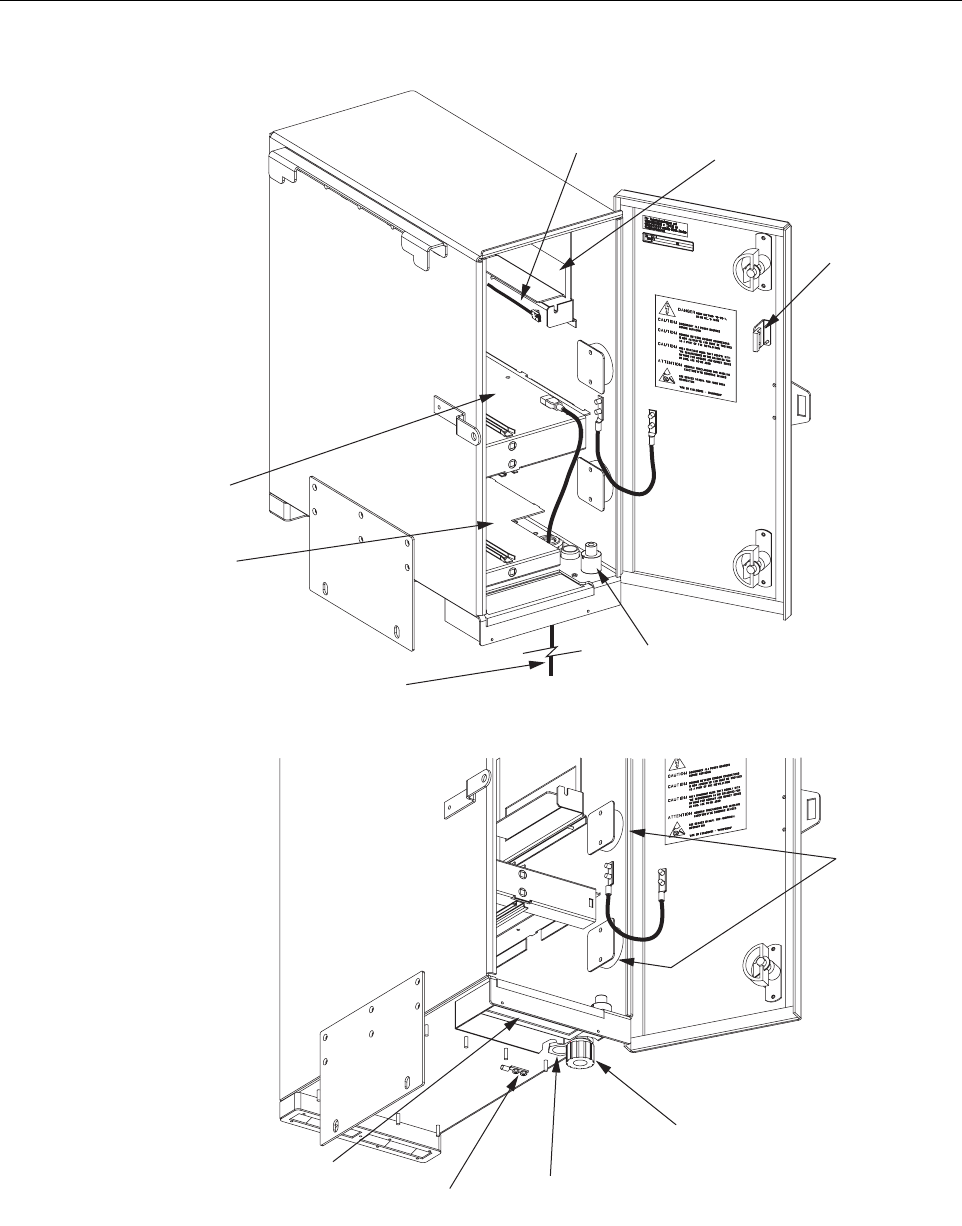
Figure 2-4. Remote Unit Outdoor Cabinet User Interface
(1) AIR INLET
FILTER 18563-B
(2) AC POWER
CABLE
(3) DOOR SWITCH
(5) STM
MOUNTING
SLOT
(4) LPA
MOUNTING
SLOT
(6) WDM/CWDM
MOUNTING SLOT
(8) FIBER
SLACK SPOOLS
(12) GROUNDING
LUG
(11) 3/4-INCH NPT
THREADED HOLE
(10) FIBER CABLE
CONNECTOR
(7) CWDM POWER
CORD
BOTTOM VIEW
OF CABINET
(9) LIGHTNING
PROTECTOR

ADCP-75-158 • Issue 1 • July 2003 • Section 2: Description
Page 2-12
© 2003, ADC Telecommunications, Inc.
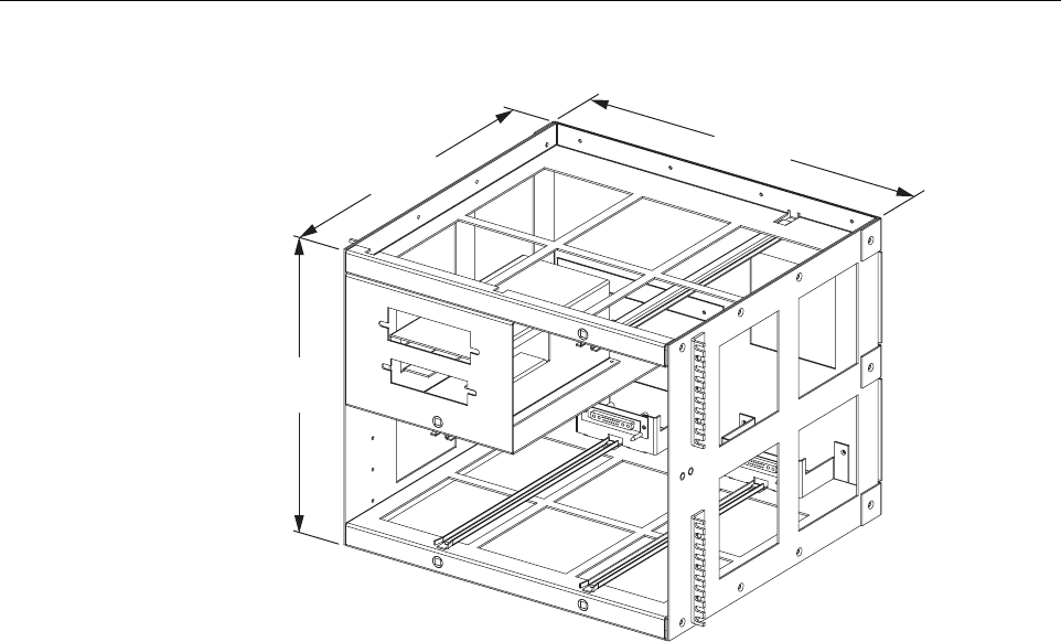
4 REMOTE UNIT INDOOR MOUNTING SHELF
The RU indoor mounting shelf, shown in Figure 2-5, is a rack-mountable framework that
provides the following basic functions:
• Supports the various electronic modules (STM and LPA) and accessories (WDM or
CWDM) for mounting within a standard 19-inch, WECO or EIA, equipment rack.
• Provides the electrical interface connections for the STM and LPA modules.
• Provides an AC power cord for powering the STM module
• Provides DC power connections for the CWDM module.
4.1 Primary Components
The RU indoor mounting shelf is a rack-mountable frame assembly that provides mounting
slots for the STM, LPA, WDM (accessory), and CWDM (accessory) modules plus connectors
and a wiring harness for interfacing the STM and LPA modules. The indoor mounting shelf is
designed for mounting in a standard 19-inch, EIA or WECO, equipment rack. The frame
assembly is constructed of aluminum and is painted putty white for corrosion protection.
Table 2-2. Remote Unit Cabinet User Interface
REF
NO DEVICE FUNCTIONAL DESCRIPTION
1 Air inlet filter Reusable filter that prevents the entry of dirt particles when out-
side air is pulled into the cabinet for cooling.
2 AC power cord Provides AC power to the STM.
3 Door switch Indicates to the fault detection and alarm reporting system if the
cabinet door is open (major alarm) or closed.
4 LPA mounting slot Provides a mounting point for the LPA module.
5 STM mounting slot Provides a mounting point for the STM module.
6 WDM/CWDM mounting
slot Provides a mounting point for either the WDM or CWDM mod-
ule.
7 CWDM power cord Provides DC power to the CWDM module.
8 Fiber slack spools Provide a storage place for excess fiber pigtail and patch cord
slack.
9 Lightning protector Provides lightning surge protection for the antenna connection.
10 Fiber cable connector Provides both an entry point and strain relief for the fiber optic
cable.
11 3/4-inch NPT threaded hole Provides a connection point for a 3/4-inch AC conduit fitting.
12 Grounding lug Provides a connection point for an external grounding cable.
ADCP-75-158 • Issue 1 • July 2003 • Section 2: Description
Page 2-13
© 2003, ADC Telecommunications, Inc.
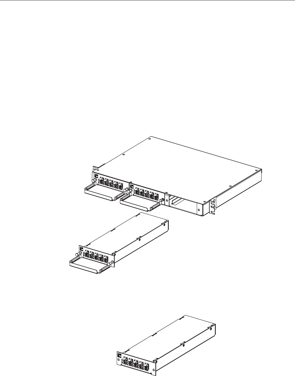
Figure 2-5. Remote Unit Indoor Mounting Shelf
4.2 STM and LPA Module Installation
Two mounting slots are provided within the indoor mounting shelf for installing the STM and
LPA modules. The mounting slots include tracks that guide each module into the installed
position. Separate mounting slots are provided for STM and LPA modules. Two D-sub
connectors (one male, one female) are located at the rear of each mounting slot. Each mounting
slot connector mates with a corresponding D-sub connector located on the rear side of each
module. A wiring harness links the mounting slot connectors together. The connectors and the
attached wiring harness provide the electrical interface between the STM and LPA modules.
The modules are held in the installed position with captive screws.
4.3 WDM and CWDM Installation
Mounting slots are provided in the indoor mounting shelf for installing a WDM or CWDM
module (accessory items). Each module is equipped with push-pull type fasteners for securing
the module to the mounting slot. A power cable is included with the mounting shelf for
supplying DC power when a CWDM module is installed.
4.4 Fiber Optic Cable Installation
Fiber optic cables and patch cords should be routed to the indoor mounting shelf using existing
fiber management systems. All fiber optic connections are made directly with the STM, WDM,
or CWDM modules. It is recommended that some provision be made at the mounting shelf for
storing excess patch cord slack.
14.15 IN.
(359 MM)
16.1 IN.
(409 MM)
17.39 IN.
(442 MM)
18565-A
ADCP-75-158 • Issue 1 • July 2003 • Section 2: Description
Page 2-14
© 2003, ADC Telecommunications, Inc.
4.5 Antenna Cable Connections
The antenna cable should be routed to the indoor mounting shelf for connection to the STM
module. If lightning protection is required, it is recommended that a lightning protector
(accessory) be installed near the point where the antenna cable enters the building or enclosure.
4.6 AC Power Wiring and Grounding
A standard three-conductor AC power cord is provided with the indoor mounting shelf for the
AC power connections. The receptacle end of the power cable connects to the AC connector on
the STM. The plug end of the power cable connects to a standard 120 VAC outlet. If AC power
spikes are likely to occur, a surge protector should be installed to protect the equipment from
damage. A grounding stud is provided on the left side of the mounting shelf for connecting a
separate grounding wire directly to the mounting shelf chassis.
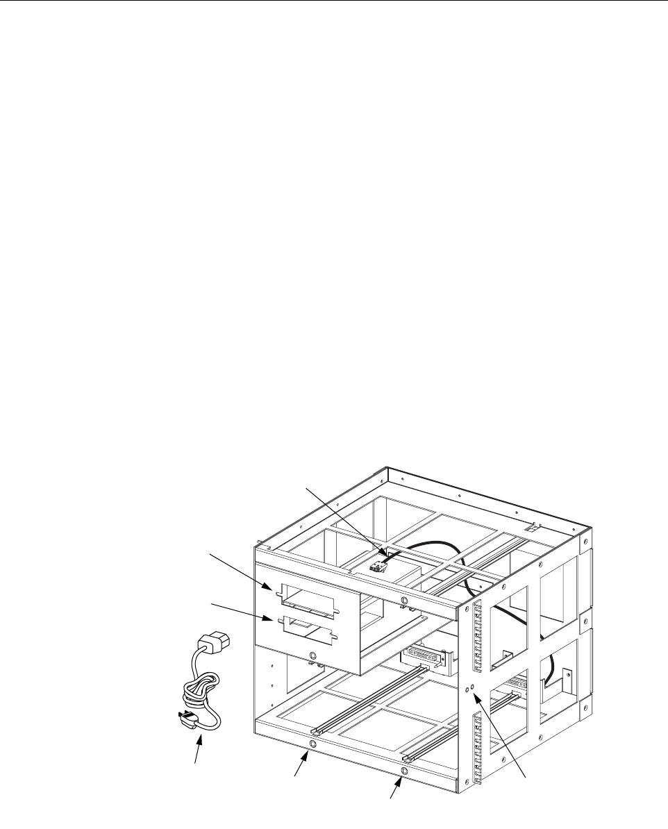
4.7 User Interface
The RU mounting shelf user interface consists primarily of the mounting slots and AC and DC
power cables. The user interface points are indicated in Figure 2-6 and described in Table 2-3.
Figure 2-6. Remote Unit Indoor Mounting Shelf User Interface
18642-A
(1) STM MOUNTING
SLOT
(2) LPA MOUNTING
SLOT
(4) AC POWER
CABLE
(5) WDM
MOUNTING
SLOT
(6) CWDM
MOUNTING
SLOT
(7) CWDM DC
POWER CABLE
(3) GROUNDING
STUDS (INSIDE)

ADCP-75-158 • Issue 1 • July 2003 • Section 2: Description
Page 2-15
© 2003, ADC Telecommunications, Inc.
5 SPECTRUM TRANSPORT MODULE
The Spectrum Transport Module (STM), shown in Figure 2-7, provides the following basic
functions:
• Provides an RF interface (antenna port) to the remote antenna.
• Provides an optical interface to the HU.
• Converts the digitized forward path optical signal to a digitized RF signal.
• Converts the digitized RF signal to a composite RF signal.
• Digitizes the reverse path composite RF signal.
• Converts the digitized reverse path RF signal to a digitized optical signal.
• Provides an RS-232 interface for connecting a local EMS computer.
• Transports alarm, control, and monitoring information to the HU via the optical link.
• Provides an AC power interface.
• Provides an external alarm interface.
5.1 Primary Components
The STM consists of an electronic circuit board assembly, power supply, duplexer, and fan
assembly that are mounted within an anodized and powder-paint coated sheet metal enclosure.
The metal enclosure provides a mounting point for the electronic components and also controls
RF emissions. Except for the fan unit, the electronic components are not user replaceable. The
STM is designed for use within the RU outdoor cabinet or indoor mounting shelf. Except for the
LPA interface connector, all controls, connectors, indicators, and switches are mounted on the
STM front panel for easy access. A carrying handle is provided on the front of the STM to
facilitate installation and transport.
Table 2-3. Remote Unit Outdoor Mounting Shelf User Interface
REF
NO DEVICE FUNCTIONAL DESCRIPTION
1 STM mounting slot Provides a mounting point for the STM module.
2 LPA mounting slot Provides a mounting point for the LPA module.
3 Grounding lug Provides a connection point for an external grounding cable.
4 AC power cable Provides AC power to the STM.
5 WDM mounting slot Provides a mounting point for the WDM module.
6 CWDM mounting slot Provides a mounting point for the CWDM module.
7 CWDM power cord Provides DC power to the CWDM module.
ADCP-75-158 • Issue 1 • July 2003 • Section 2: Description
Page 2-16
© 2003, ADC Telecommunications, Inc.
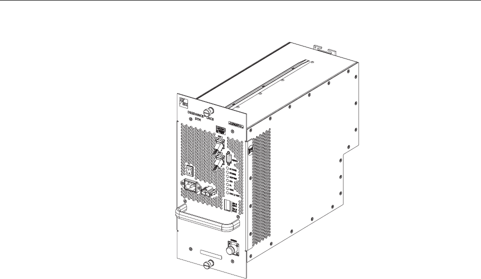
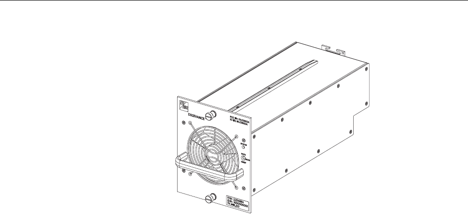
Figure 2-7. Spectrum Transport Module
5.2 Mounting
The STM mounts within the RU outdoor cabinet or indoor mounting shelf. Runners on the top
and bottom of the STM mesh with tracks. The runners and tracks guide the STM into the
installed position. The electrical interface between the STM and LPA is supported by a D-sub
female connector located on the rear side of the STM. A corresponding D-sub male connector
mounted at the rear of the RU cabinet or RU mounting shelf mates with the STM connector.
Captive screws are provided for securing the STM in the installed position.
5.3 Fault Detection and Alarm Reporting
The STM detects and reports various faults including remote unit fault, optical fault, power
fault, temperature fault, power amplifier fault, and external (door open) fault. Various front
panel Light Emitting Diode (LED) indicators turn from green to red or yellow if a fault is
detected. The status of the STM, the alarm state (major or minor), and other alarm information
is summarized and reported over the optical interface to the HU and also over the service
interface. In addition, the alarm state of the HU is received over the optical interface and
reported to the service interface. This information may be accessed remotely through the NOC/
NEM interface or locally through the EMS software GUI.
5.4 Antenna Cable Connection
The antenna cable connections between the STM and the antenna are supported through one N-
type female connector which carries both the forward and reverse path RF signals. When
installed in the RU outdoor cabinet, the STM does not connect directly to the antenna but
18634-B

ADCP-75-158 • Issue 1 • July 2003 • Section 2: Description
Page 2-17
© 2003, ADC Telecommunications, Inc.
instead connects to a lightning protector that is mounted on the bottom of the cabinet (see
Section 3.6). A coaxial jumper cable is provided (included with the enclosure) for connecting
the STM to the lightning protector.
5.5 RF Signal Level Adjustment
The STM is equipped with a digital attenuator for adjusting the signal level of the forward path
RF output signal. The remote forward path attenuator adjusts the level of the output RF signal
at the RU antenna port and will add from 0 to 31 dB of attenuation to the output signal level.
The attenuator can be set in 1 dB increments. The attenuator is software controlled and is
adjusted through the NOC/NEM interface or the EMS software GUI.
5.6 Optical Connection
Fiber optic connections between the STM and the HU are supported through two SC-type
optical connector ports. One port is used for connecting the forward path optical signal and the
other port is used for connecting the primary reverse path optical signal.
5.7 Service Interface Connection
The service interface connection between the STM and a local laptop computer loaded with the
EMS software is supported by a single DB-9 female connector. The service interface connector
provides an RS-232 DTE interface. The STM service interface connector supports local
communications with both the STM and the corresponding HU.
5.8 Powering
The STM is powered by 120 or 240 VAC (50 or 60 Hz) power which is supplied through a
three-conductor AC power cord. The power cord is provided with the RU outdoor cabinet or
indoor mounting shelf. The power cord connects to an AC connector mounted on the STM front
panel. A switch on the STM front panel provides AC power On/Off control.
5.9 Cooling
Continuous air-flow for cooling is provided by a single fan mounted on the rear side of the STM
housing. An alarm is provided that indicates if a high temperature condition (>50º C/122º F)
occurs. If the temperature falls below 32º F (0º C), the fan automatically shuts off. The fan may
be field replaced if it fails.
5.10 User Interface
The STM user interface consists of the various connectors, switches, and LEDs that are
provided on the STM front panel. The STM user interface points are indicated in Figure 2-8 and
described in Table 2-4.
ADCP-75-158 • Issue 1 • July 2003 • Section 2: Description
Page 2-18
© 2003, ADC Telecommunications, Inc.
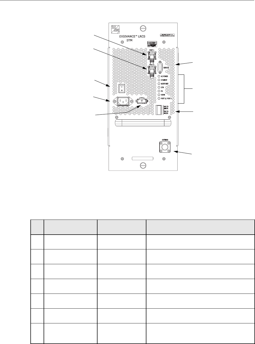
Figure 2-8. Spectrum Transport Module User Interface
Table 2-4. Spectrum Transport Module User Interface
REF
NO
USER INTERFACE
DESIGNATION DEVICE FUNCTIONAL
DESCRIPTION
1 PORT 1 SC connector
(single-mode) Input connection point for the forward path opti-
cal fiber.
2 PORT 2 SC connector
(single-mode) Output connection point for the reverse path pri-
mary optical fiber.
3I/0 On/Off rocker
switch Provides AC power on/off control.
4 No designation 3-wire AC power
cord connector Connection point for the AC power cord.
5 No designation 2- wire DC power
cord connector Connection point for a back-up battery power
cord. (Not used with 20 Watt system)
6 SERVICE DB-9 connector
(female) Connection point for the RS-232 service inter-
face cable.
7 AC POWER Multi-colored LED
(green/red)
Indicates if the STM is powered by the AC power
source (green) or the back-up battery system
(red). See Note.
18636-B
(3) ON/OFF
SWITCH
(4) AC POWER
CONNECTOR
(5) DC POWER
CONNECTOR
(1) PORT 1
CONNECTOR
(2) PORT 2
CONNECTOR
(6) SERVICE
CONNECTOR
(7-13) LED
INDICATORS
(14) ALARM
CONNECTOR
(15) ANTENNA
CONNECTOR

ADCP-75-158 • Issue 1 • July 2003 • Section 2: Description
Page 2-19
© 2003, ADC Telecommunications, Inc.
6 LINEAR POWER AMPLIFIER
The Linear Power Amplifier (LPA), shown in Figure 2-9, works in conjunction with the STM to
amplify the forward path RF output signal. The STM is interfaced with the LPA through the
D-sub connectors and wiring harness located at the rear of the RU cabinet or RU mounting
shelf. The RF signal is passed to the LPA for amplification and then passed back to the STM for
filtering and output via the STM’s ANTENNA port. The STM also supplies DC power to the
LPA through the same interface.
6.1 Primary Components
The LPA consists of a fan and several electronic circuit board assemblies that are mounted
within a powder-paint coated sheet metal enclosure. The metal enclosure provides a mounting
point for the electronic components and also controls RF emissions. Except for the fan unit, the
electronic components are not user replaceable. The LPA is designed for use within the RU
outdoor cabinet or RU indoor mounting shelf. Except for the STM interface connector, all
controls, indicators, and switches are mounted on the LPA front panel for easy access. A
carrying handle is provided on the front of the LPA to facilitate installation and transport.
8 STANDBY Multi-colored LED
(green/yellow/red)
Indicates if the system is in the Normal state (off)
Standby state (blinking green), Test state (blink-
ing red), or Program Load state (blinking yel-
low). See Note.
9 HOST UNIT Multi-colored LED
(green/yellow/red)
Indicates if no alarm (green), a minor alarm (yel-
low), or a major alarm (red) is reported by the
HU. See Note.
10 STM Multi-colored LED
(green/yellow/red)
Indicates if the STM is normal (green) or faulty
(red). See Note.
11 PA Multi-colored LED
(green/yellow/red)
Indicates if the power amplifier is normal
(green), over temperature (yellow), has a fan fail-
ure (yellow), or is faulty (red). See Note.
12 VSWR Multi-colored LED
(green/yellow/red)
Indicates if the forward path VSWR is above
(red) or below (green) the fault threshold.
13 PORT 1/PORT 2 Multi-colored LED
(green/red)
Indicates if the forward/reverse path optical sig-
nal from the STM/HU are normal (green), if no
optical signals are detected (red), or if excessive
errors are detected (red). See Note.
14 ALARM IN MINOR
ALARM IN MAJOR
Screw-type terminal
connector (14–26
AWG)
Connection point for two external alarm inputs.
The door-open switch lead wires are typically
connected to the major alarm terminals.
15 ANTENNA N-type female RF
coaxial connector Connection point for the antenna.
Note: A more detailed description of LED operation is provided in Section 5.
Table 2-4. Spectrum Transport Module User Interface, continued
REF
NO
USER INTERFACE
DESIGNATION DEVICE FUNCTIONAL
DESCRIPTION
ADCP-75-158 • Issue 1 • July 2003 • Section 2: Description
Page 2-20
© 2003, ADC Telecommunications, Inc.
Figure 2-9. Linear Power Amplifier
6.2 Mounting
The LPA mounts within the RU outdoor cabinet or RU indoor mounting shelf. Runners on the
top and bottom of the LPA mesh with tracks. The runners and tracks guide the LPA into the
installed position. The electrical interface between the STM and LPA is supported by a D-sub
female connector located on the rear side of the LPA. A corresponding D-sub male connector
mounted at the rear of the RU outdoor cabinet or RU indoor mounting shelf mates with the LPA
connector. Captive screws are provided for securing the LPA in the installed position.
6.3 Fault Detection and Alarm Reporting
The LPA in conjunction with the STM detects and reports various faults including power
amplifier fault, output power fault, temperature fault, and fan fault. A single Light Emitting
Diode (LED) indicator, located on the front panel of the LPA, turns from green to red or yellow
if an LPA fault is detected. The status of the LPA, the alarm state (major or minor), and other
information is summarized and reported (by the STM) over the optical fiber to the HU and also
to the service interface. This information may be accessed remotely through the NOC/NEM
interface or locally through the EMS software GUI.
6.4 Powering
The LPA is powered by various DC voltages which are supplied by the STM over the electrical
interface provided by the D-sub connectors and wiring harness mounted within the RU outdoor
cabinet or RU indoor mounting shelf.
18796-A
1900 MHz 20 WATT

ADCP-75-158 • Issue 1 • July 2003 • Section 2: Description
Page 2-21
© 2003, ADC Telecommunications, Inc.
6.5 Cooling
Continuous air-flow for cooling is provided by a fan mounted at the front of the LPA housing.
Cool air is pulled into the module from the front and heated air is exhausted out the back. An
alarm is provided that indicates if a high temperature condition (>50º C/122º F) occurs or if a
fan failure occurs. The fan may be field replaced if it fails.
6.6 User Interface
The LPA user interface consists of an LED indicator and a switch that are mounted on the LPA
front panel. The LPA user interface points are described in Table 2-5 and indicated in
Figure 2-10.
Figure 2-10. Linear Power Amplifier User Interface
Table 2-5. Linear Power Amplifier User Interface
REF
NO
USER INTERFACE
DESIGNATION DEVICE FUNCTIONAL
DESCRIPTION
1 STATUS LED indicator
(green, yellow, and
red)
Indicates the operational state of the LPA and
whether or not there are any faults.
2MUTE
NORM
RESET
3-position switch
with one momentary
contact position
Placing the switch in the MUTE position puts the
LPA in the shutdown state with RF output disabled.
With the switch in MUTE, the STM can not control
the LPA output power. Placing the switch in the
NORM position puts the LPA in the normal state
and allows the STM to enable and disable the RF
output. Momentarily placing the switch in the
RESET position clears all alarms and restarts the
LPA.
Note: A more detailed description of the STATUS LED is provided in Section 5.
18797-A
(1) STATUS
(2) MUTE/NORM/
RESET SWITCH
1900 MHz 20 WATT
ADCP-75-158 • Issue 1 • July 2003 • Section 2: Description
Page 2-22
© 2003, ADC Telecommunications, Inc.
7 INTERFACE PANELS (ACCESSORY)
The interface panels are accessory items that are used when multiple BTS’s and multiple HU’s
require connection or when RF attenuation is needed between the BTS and HU. Two types of
panels are available: the Conditioning Panel and the Duplexing Panel. The Conditioning Panel,
shown in Figure 2-11, provides attenuation of the forward path signal to the level required for
input to the HU. The Conditioning Panel also provides forward and reverse path combining and
splitting (as needed) to enable multi-BTS to single HU, multi-BTS to multi-HU, or single BTS
to multi-HU configurations.
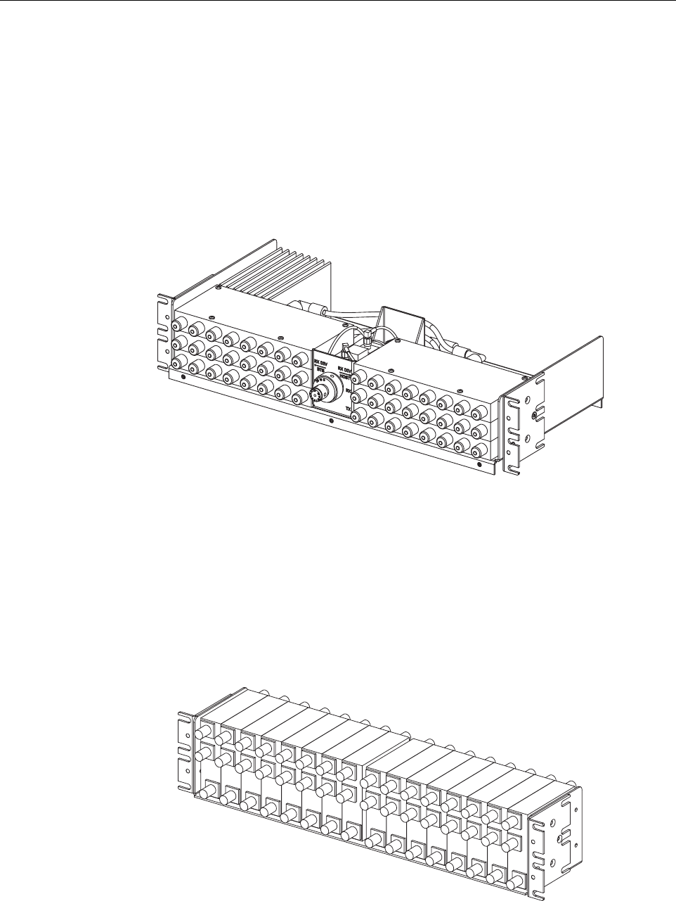
Figure 2-11. Conditioning Panel
The Duplexing Panel, shown in Figure 2-12, is used in conjunction with the Conditioning Panel
when the BTS provides a duplexed forward and reverse path RF connection. The Duplexing
Panel separates the duplexed forward and reverse path signals. This allows the BTS to be
connected to the HU which has separate forward and reverse path RF ports. For complete
information about the Conditioning Panel and Duplexing Panel, refer to the Digivance RF
Transport Solution 800 and 1900 MHz Interface Panels User Manual (ADCP-75-144).
Figure 2-12. Duplexing Panel
18644-A
18645-A
ADCP-75-158 • Issue 1 • July 2003 • Section 2: Description
Page 2-23
© 2003, ADC Telecommunications, Inc.
8 WAVELENGTH DIVISION MULTIPLEXER SYSTEM (ACCESSORY)
The Wavelength Division Multiplexer (WDM) system is an accessory product that is used when
it is desirable or necessary to combine the forward and reverse path optical signals from one
Digivance system onto a single optical fiber. Each WDM system consists of a host module, host
module mounting shelf, and remote module. The WDM host module mounting shelf can
support two WDM host modules. The RU indoor mounting shelf provides a mounting slot for
installing a WDM remote module.
Each WDM module consists of either one (remote module) or two (host module) bi-directional
wavelength division multiplexers mounted within a power-paint coated sheet metal enclosure.
An SC-type optical connector port is provided for connecting the forward/reverse path optical
fiber to the WDM module. A pair of pigtail leads with SC-type connectors are provided for
connecting the WDM module to the forward and reverse path optical ports on the HU or STM.
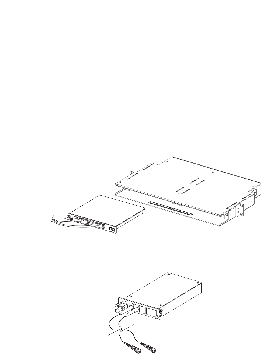
The WDM host module and host module mounting shelf are shown in Figure 2-13. The WDM
remote module is shown in Figure 2-14.
Figure 2-13. WDM Host Module and Host Module Mounting Shelf
Figure 2-14. WDM Remote Module
18646-A
17013-A
ADCP-75-158 • Issue 1 • July 2003 • Section 2: Description
Page 2-24
© 2003, ADC Telecommunications, Inc.
9 COARSE WAVELENGTH DIVISION MULTIPLEXER SYSTEM (ACCESSORY)
The Coarse Wavelength Division Multiplexer (CWDM) system is an accessory product that is
used when it is desirable or necessary to combine the forward and reserve path optical signals
for up to four Digivance systems onto a single optical fiber. Each CWDM system consists of a
Host Module, Host Module mounting shelf, and Remote Module. The CWDM Host Module
mounting shelf can support up to three CWDM Host Modules. Both the RU outdoor cabinet and
indoor mounting shelf provide a mounting slot for installing a CWDM Remote Module.
The CWDM Host Module and Host Module Mounting Shelf are shown in Figure 2-15. The
CWDM Remote Module is shown in Figure 2-16. For complete information about the CWDM
system, refer to the Digivance System Coarse Wavelength Division Multiplexer User Manual
(ADCP-75-142).
Figure 2-15. CWDM Host Module and Host Module Mounting Shelf
Figure 2-16. CWDM Remote Module
18647-A
18648-A
ADCP-75-158 • Issue 1 • July 2003 • Section 2: Description
Page 2-25
© 2003, ADC Telecommunications, Inc.
10 DIGIVANCE ELEMENT MANAGEMENT SYSTEM
The Digivance Element Management System (EMS) is a network management tool that provides
control and monitoring functions for the Digivance system. The EMS is used to provision and
configure new systems for operation, set system operating parameters, get system alarm and
status messages, and upgrade the system software. The EMS supports both local control by an
on-site service technician and remote control by a Network Operations Center (NOC).
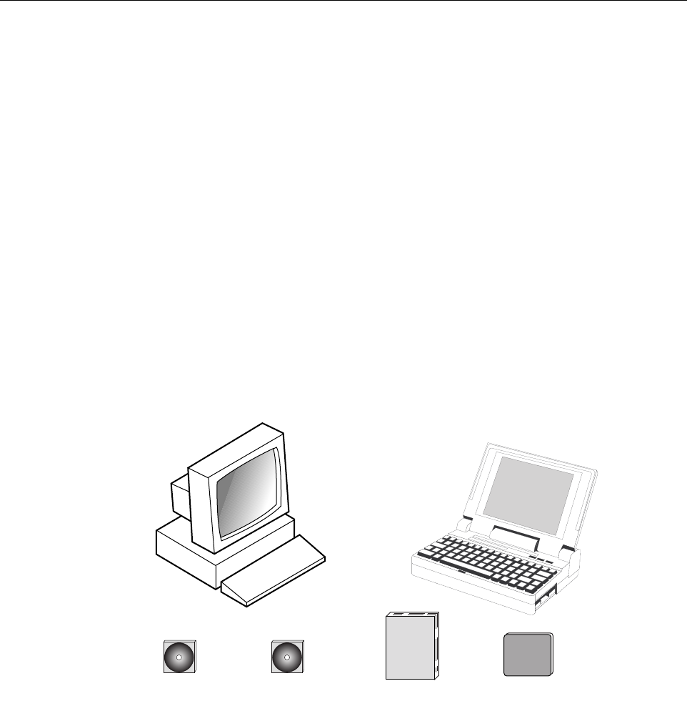
10.1 Primary Components
The EMS, shown in Figure 2-17, consists of a PC-type desk-top computer (not provided) that is
loaded with the EMS software. The EMS software is stored on a CD-ROM that is shipped
separately along with a User Manual and mouse pad. The EMS software must be installed on
the EMS computer along with the Java 2 Version 1.3.1 Runtime Environment software which is
also provided. Installation consists of inserting the CD-ROM into the computer’s CD-ROM
drive and then running the software install programs. This places the Java 2 Runtime
Environment and EMS software files in assigned folders on the computer’s hard drive.
Figure 2-17. Digivance Element Management System
The EMS software may also be installed on a PC-type lap-top computer (not provided). A lap-
top version of the EMS computer can be used as a portable network management tool for
service and maintenance purposes. A laptop EMS computer can be connected temporarily to a
system to enter the initial configuration data or to trouble-shoot problems and then removed
when the task is completed. Permanent control and monitoring functions would be provided by
the desk-top EMS computer.
EMS CD-ROM MANUALS CD-ROM
OR
NOTE: COMPUTER
NOT PROVIDED
16803-C
USER MANUAL MOUSE PAD
ADCP-75-158 • Issue 1 • July 2003 • Section 2: Description
Page 2-26
© 2003, ADC Telecommunications, Inc.
10.2 Service Interface Connection
The service interface connection between the EMS computer and the HU or RU requires that
the EMS computer be equipped with a DB-9 connector that is configured to provide an RS-232
DCE interface. A straight-through RS-232 interface cable (accessory item) equipped with a
male DB-9 connector on one end and a PC-compatible connector on the other end is required to
link the EMS computer to the HU. When multiple HUs are networked together, the EMS
computer may be connected to the service connector on any one of the networked HUs.
10.3 NOC Interface Connection
The NOC interface connection between the EMS computer and the NOC requires that the EMS
computer be equipped with a connector that is configured to provide an RS-232 ASCII
interface. The link between the EMS computer and the NOC would generally be supported by a
data network. Cables and equipment (not provided) to support the RS-232 interface connection
between the EMS computer and the data network are required.
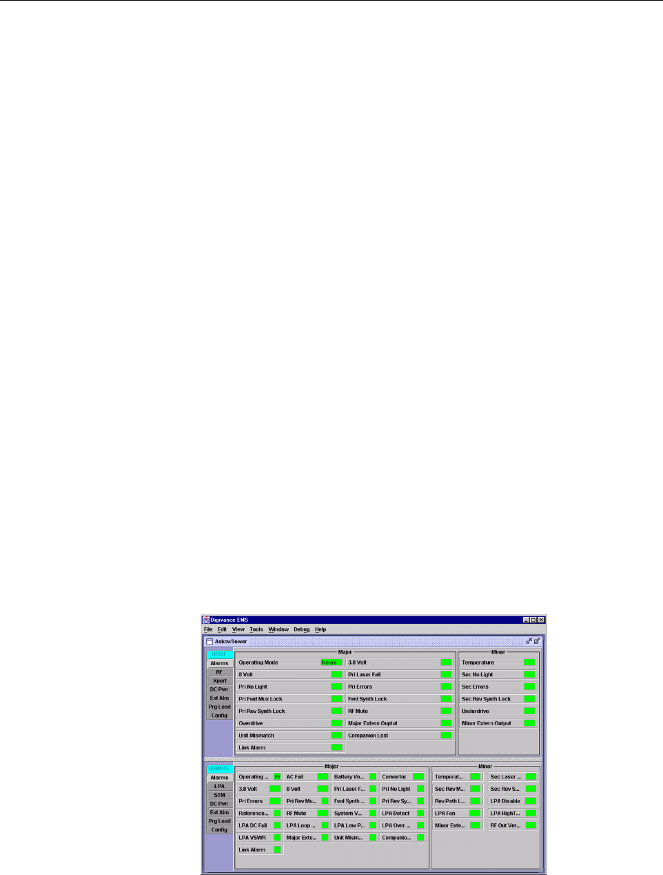
10.4 EMS Software User Interface
The EMS software provides two user interfaces: the Graphical User Interface (GUI) and the
Network Operation Center-Network Element Manager (NOC/NEM) interface. Both interfaces
provide essentially the same functionality except only the GUI can upgrade the Digivance
system with new system software. In addition, only the NOC/NEM interface can record and
play back alarm data.
The GUI is presented at the EMS computer or on a laptop computer. The GUI is used for local
control and monitoring operations. The GUI consists of a series of displays and screens, such as
the one shown in Figure 2-18, that provide the user with alarm and status information and that
allow the user to set various operating parameters.
Figure 2-18. EMS Graphical User Interface Host/Remote Display