ADC Telecommunications DLC1902B Digivance® LRCS 1900 MHz, 20-Watt LPA User Manual 75158
ADC Telecommunications Inc Digivance® LRCS 1900 MHz, 20-Watt LPA 75158
Contents
User manual 5
ADCP-75-158 • Issue 1 • July 2003 • Section 4: Operation
Page 4-7
© 2003, ADC Telecommunications, Inc.
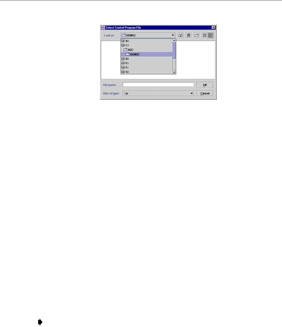
Figure 4-4. Select Control Program File Window
4. Select the first file to download and click on the OK button.
5. Click on the HOST Load button (see Figure 4-3) to start the download.
6. Repeat steps 4 and 5 for each file that requires downloading.
7. Repeat steps 2 through 5 for the REMOTE.
2.3 Determine Forward Path Input Signal Level
The level of the composite RF input signal at the FORWARD RF IN port at the HU will vary
depending on the type of BTS, the cable loss, the number of channels present, and the required
forward path composite power. If maximum composite RF output is required, the signal level of
the composite forward path RF signal at the HU forward path input must be adjusted to fall
within a range of –9 to –40 dBm. If the signal level is not within this range, it must be adjusted
to fall within this range through the use of an external attenuator capable of handling the BTS
forward path output power.
If using the Conditioning Panel or Duplexing Panel, refer to the Digivance 800 and 1900 MHz
Interface Panels User Manual (ADCP-75-147) for the procedures for measuring and adjusting
the input RF signal level at the HU. If connecting a single HU to a single BTS, use the following
procedure to measure and adjust the input RF signal level at the HU:
1. Connect a spectrum analyzer or power meter to the forward path output port of the BTS.
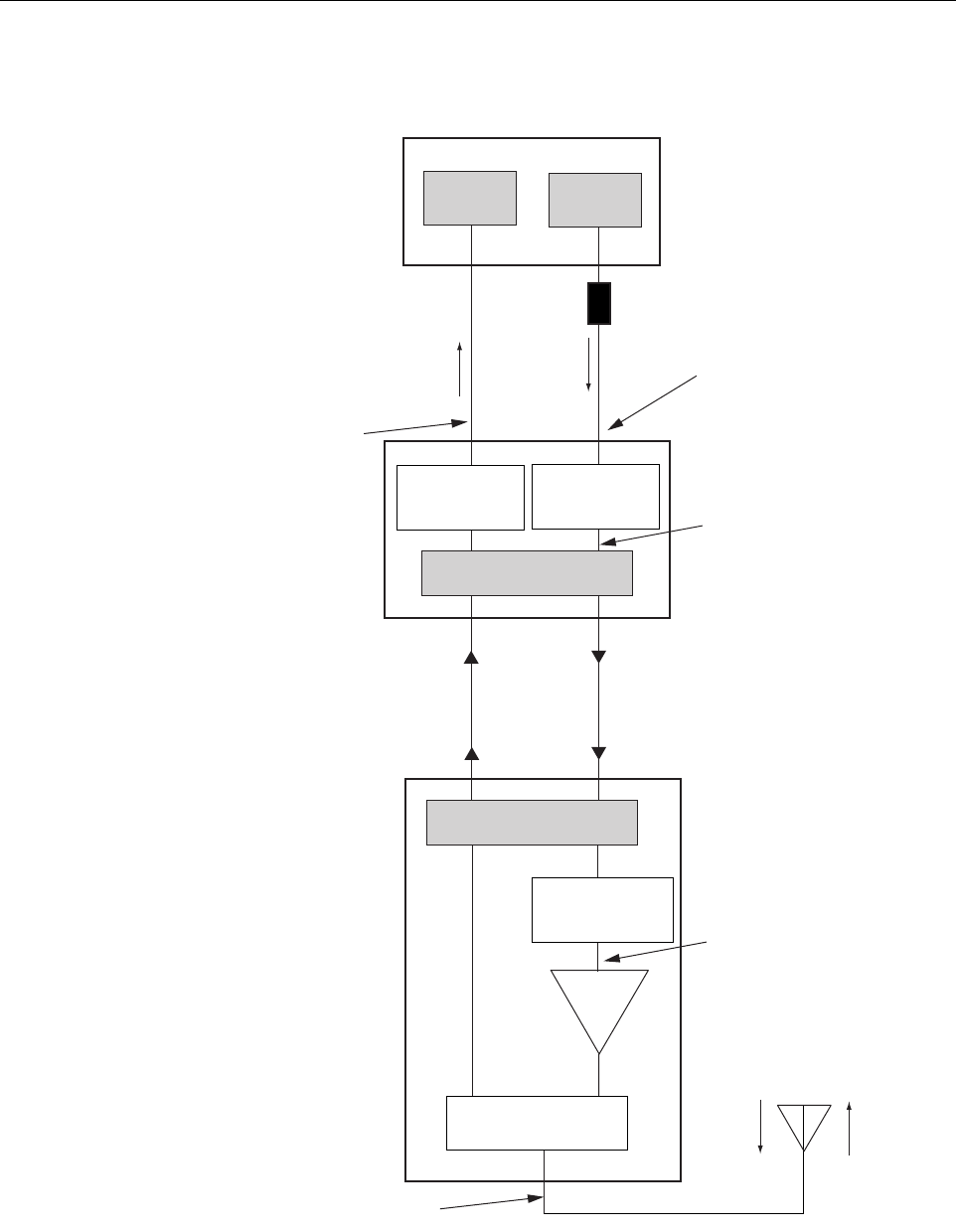
The required signal levels and test points are shown in Figure 4-5.
2. If using a spectrum analyzer, proceed to step 3. If using a power meter, measure the
composite signal power from the BTS and then proceed to step 5.
3. Measure the RF level of a single carrier, such as the control channel, in dBm. Make sure
the resolution bandwidth of the spectrum analyzer is 30 kHz. Maximum power in any
channel should not exceed 5W (+37 dB).
Note: Check the input rating of the test equipment and the output rating of the BTS. To
avoid burning out the spectrum analyzer or power meter, it may be necessary to insert a
30 dB 100W (or similar) attenuator between the BTS and test equipment.

ADCP-75-158 • Issue 1 • July 2003 • Section 4: Operation
Page 4-8
© 2003, ADC Telecommunications, Inc.
4. Calculate the total composite signal power from the BTS using the following formula:
Ptot = Pc + 10Log N – (see Note)
Where,
Ptot is the total composite power in dBm
Pc is the power per carrier in dBm as measured in step 3, and
N is the total number of channels.
5. Determine the total cable loss that is imposed by the forward path coaxial cable that links
the BTS to the HU and also any insertion loss imposed by splitters or combiners.
6. Subtract the total cable loss and any insertion losses from the total composite power
calculated in step 4.
7. Subtract –25 (midpoint of the required range) from the value determined in step 6. The
difference (which should be positive) equals the value of the external attenuator that is
required to reduce the forward path signal level to fall within the required range. The
following formula outlines the required calculations for steps 6 and 7:
Ptot – (Cable and insertion loss) – (–25) = Value of external attenuator required
8. Select an attenuator that is as close to the value calculated in step 7 as possible. Select a
value that will adjust the signal level of the composite input signal to fall within the
specified range.
9. Install the external attenuator in the coaxial cable that is connected to the FORWARD RF
IN port at the HU.
10. Subtract the value of the external attenuator used in step 9 from the total composite signal
power (Ptot) and record the result. This value will be required when setting the attenuation
of the HU’s internal forward attenuator.
Note: If calculating the composite power for a CDMA system, reduce the initial result by
16.23 dB.
Note: If the input signal level is already within the required range of –9 to –40 dBm, then
no external attenuator is required.
Caution: The Host Unit can be damaged if it is overdriven by the BTS. Always install an
external protective attenuator at the Host Unit FORWARD RF IN port if the forward path
composite input signal level is greater than –9 dBm.
ADCP-75-158 • Issue 1 • July 2003 • Section 4: Operation
Page 4-9
© 2003, ADC Telecommunications, Inc.
Figure 4-5. Signal Levels, Test Points, and Adjustments
INPUT SIGNAL LEVEL
(-25 dBm TYPICAL
COMPOSITE FOR
FULL POWER)
HOST UNIT
PRIMARY
ANTENNA
LPA
REMOTE UNIT
BASE
TRANSCEIVER STATION
17000-C
EXTERNAL
ATTENUATOR
TRANS-
MITTERS
RECEIVERS
0 to 31 dB
ATTENUATOR
(HOST REV ATT)
0 to 31 dB
ATTENUATOR
(HOST FWD ATT)
RF, OPTICS,
AND CONTROL
0 to 31 dB
ATTENUATOR
(REMOTE FWD ATT)
OPTICAL LINK
RF, OPTICS,
AND CONTROL
DUPLEXER
ADJUSTMENTS TO INPUT
SIGNAL LEVEL AS SET BY HOST
FORWARD PATH ATTENUATOR
ADJUSTMENTS TO OUTPUT
SIGNAL LEVEL AS SET BY HOST
REVERSE PATH ATTENUATOR
MAXIMUM OUTPUT SIGNAL
LEVEL AT STM ANTENNA PORT
ADJUSTMENTS TO
OUTPUT SIGNAL LEVEL
AS SET BY THE REMOTE
FORWARD ATTENUATOR
ADCP-75-158 • Issue 1 • July 2003 • Section 4: Operation
Page 4-10
© 2003, ADC Telecommunications, Inc.
2.4 Enter Site Name and Site Number
All HU’s and RU’s are programmed with the same site name and site number. It is therefore
necessary to assign a unique site name and site number to the HU and RU before they can be
connected to the same CAN. Use the following procedure to assign a unique site name and
number to each HU and RU system:
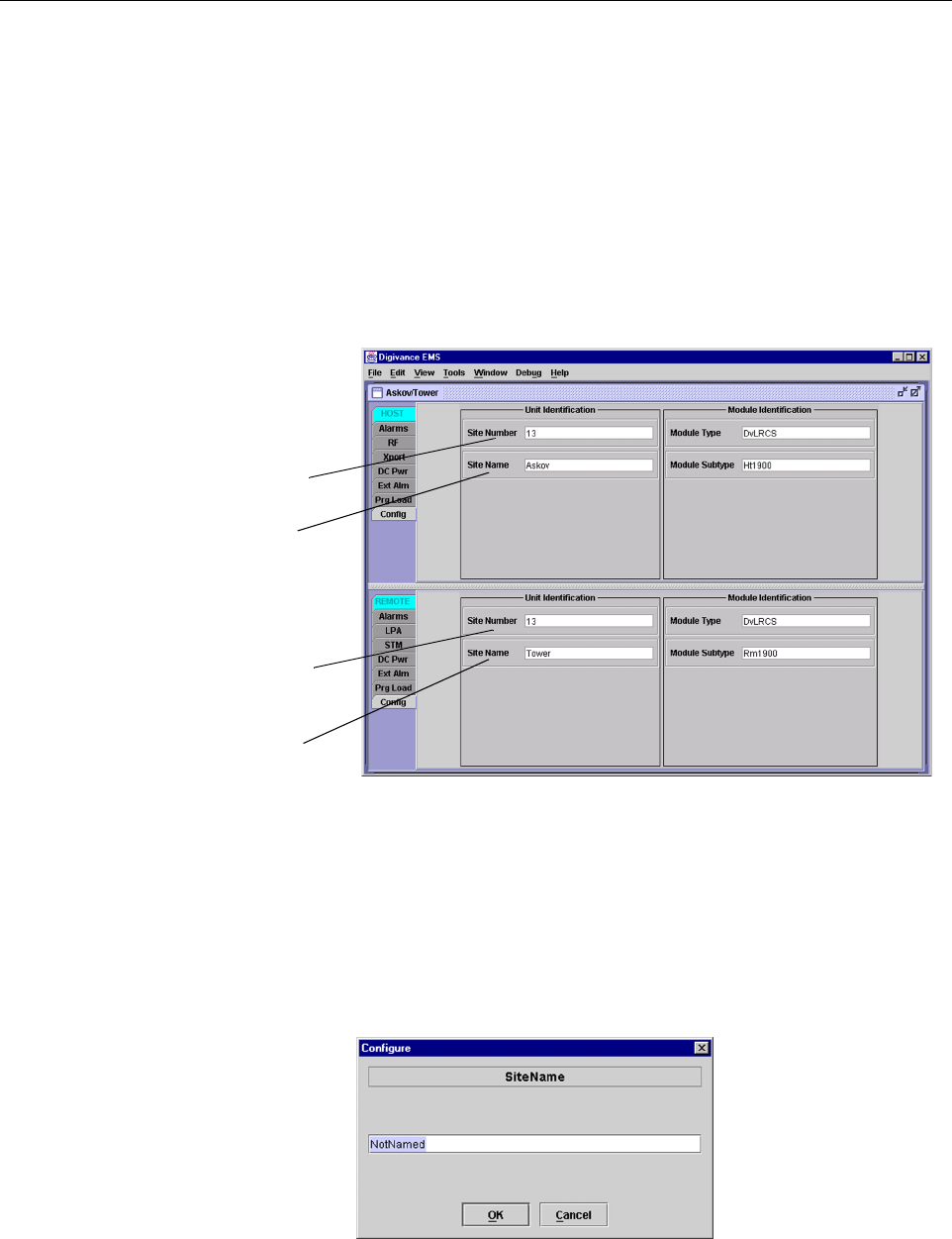
1. Click on the HOST Config tab and on the REMOTE Config tab. The HOST Config
display and the REMOTE Config display will open within the EMS main window as
shown in Figure 4-6.
Figure 4-6. HOST and REMOTE Config Displays
2. Right-click on the HOST Site Name field (see Figure 4-6). The Site Name pop-up screen
will open as shown in Figure 4-7. Enter a unique name for the HOST. The name may be up
to 32 characters long and must not contain any spaces. The name may include numbers,
punctuation, and upper or lower case letters and must always begin with a letter. Click on
OK to close the screen and make the changes take effect.
Figure 4-7. HOST Site Name Pop-Up Screen
HOST Site Number
HOST Site Name
REMOTE Site Number
(Entered automatically
when the HOST site
number is selected)
REMOTE Site Name
Right-Click on the
point shown to open
pop-up screen

ADCP-75-158 • Issue 1 • July 2003 • Section 4: Operation
Page 4-11
© 2003, ADC Telecommunications, Inc.
3. Right-click on the HOST Site Number (see Figure 4-6). The Site Number pop-up screen
will open. Enter any number between 1 and 24 and then click on OK to close the screen
and make the changes take effect.
4. Check the REMOTE Site Number field (see Figure 4-6). The REMOTE Site Number
does not have to be entered. When the HOST Site Number is entered, the system will
automatically enter the same number for the REMOTE Site Number.
5. Right-click on the REMOTE Site Name field (see Figure 4-6). The Site Name pop-up
screen will open. Enter a unique name for the REMOTE. The name may be up to 32
characters long and must not contain any spaces. The name may include numbers,
punctuation, and upper or lower case letters and must always begin with a letter. Click on
OK to close the screen and make the changes take effect.
6. Open the Tools menu at the top of the main window and then select Refresh Catalog to
make the new Host and Remote site names appear in the View menu.
2.5 Enter Host Forward Attenuation
The HU internal forward path attenuator setting determines the maximum composite output
signal level at the STM antenna port. The appropriate attenuation value for any particular
system is based on the number of channels the system is transporting and the level of the
composite forward path signal input at the HU’s FORWARD RF IN port. The maximum output
power that can be provided by the system is 40.5 dBm (11 Watts). The total forward path gain
that is provided by the system (with host and remote forward attenuators set to 0 dB) is 80.5
dBm. Use the following procedure to set the forward path attenuation to provide the maximum
composite output signal level:
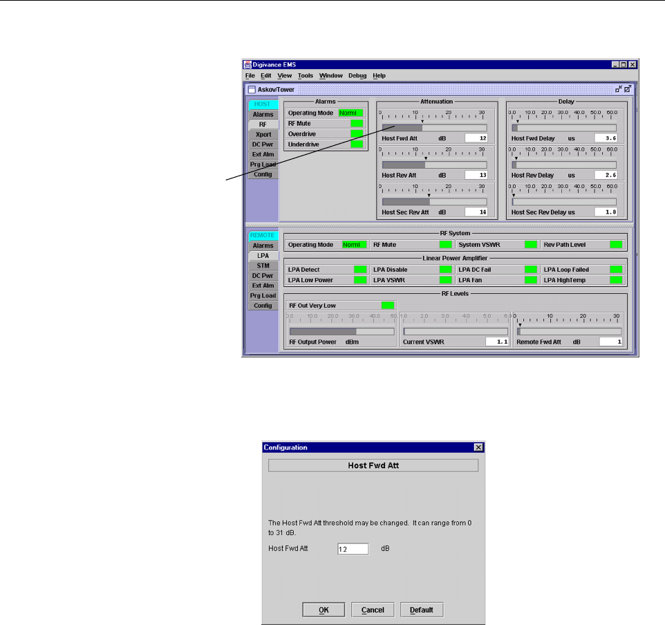
1. Click on the HOST RF tab. The HOST RF display will open within the EMS main
window as shown in Figure 4-8.
2. Right-click on the Host Fwd Att section of the display (see Figure 4-8). The Host Fwd
Att pop-up screen will open as shown in Figure 4-9.
3. Obtain the value of the total composite input signal level as determined in step 10 of
Section 2.3.
4. Determine the appropriate value to enter for the Host forward path attenuator by
subtracting the required system output level (per system design plan) from 80.5 (the total
system gain) and then adding the composite input signal level. The result (see sample
calculation) is the amount of attenuation required.
Atten Required = 80.5 – (Required System Output Power) + (Composite Input Power)
5. Enter the attenuation value and click OK to close the pop-up screen and to make the
changes take effect.
ADCP-75-158 • Issue 1 • July 2003 • Section 4: Operation
Page 4-12
© 2003, ADC Telecommunications, Inc.
Figure 4-8. HOST RF Display
Figure 4-9. Host Fwd Att Pop-Up Screen
2.6 Determine Output Signal Level at STM Antenna Port
The RF output signal level should be measured at the STM ANTENNA port to verify that
maximum composite signal level is at the required level. Use the following procedure to
determine the power level:
1. Verify that RF ON/OFF switch on the LPA in the OFF position.
2. Disconnect the antenna cable from the STM ANTENNA port.
3. Connect a spectrum analyzer or RF power meter to the STM ANTENNA port. (Check the
input rating of the test equipment. Insert a 30 dB 100 W attenuator if necessary.)
Right-click here
to open Host Fwd
Att pop-up screen

ADCP-75-158 • Issue 1 • July 2003 • Section 4: Operation
Page 4-13
© 2003, ADC Telecommunications, Inc.
4. Place the RF ON/OFF switch on the LPA in the ON position.
5. If using a spectrum analyzer, proceed to step 6. If using a power meter, measure the
composite signal power from the STM and then proceed to step 8.
6. Measure the RF level of a single carrier, such as the control channel, in dBm. Make sure
the resolution bandwidth of the spectrum analyzer is 30 kHz.
7. Calculate the total composite signal power using the following formula:
Ptot = Pc + 10Log N – (see Note)
Where,
Ptot is the total composite power in dBm
Pc is the power per carrier in dBm as measured in step 6, and
N is the total number of channels.
8. Record the result measured in step 5 or calculated in step 7.
9. Place the MUTE/NORM/RESET switch on the LPA in the OFF position.
10. Disconnect the spectrum analyzer or RF power meter from the STM ANTENNA port.
11. Re-connect the antenna cable to the STM ANTENNA port.
2.7 Enter Remote Forward Attenuation
The STM internal forward path attenuator setting is used to reduce the power level of the
composite output signal level at the STM antenna port. The maximum composite output signal
level at the STM antenna port is set using the Host internal forward attenuator (see Section 2.4).
However, component variations may result in the output power at the STM antenna port being
slightly above or below the required power per channel. If this is the case, the STM forward
attenuator may be used in conjunction with the Host forward attenuator to add or remove
attenuation to produce the required output signal level. If less power is required, the STM
forward attenuator may be used to reduce the power level. The default setting is 0 dB. Use the
following procedure to change the STM forward attenuation:
1. Click on the REMOTE LPA tab. The REMOTE LPA display will open within the EMS
main window as shown in Figure 4-10.
Note: If calculating the composite power for a CDMA system, reduce the initial result by
16.23 dB.
Note: To comply with Maximum Permissible Exposure (MPE) requirements, the
maximum composite output from the antenna cannot exceed 1000 Watts EIRP and the
antenna must be permanently installed in a fixed location that provides at least 6 meters
(20 feet) of separation from all persons.
ADCP-75-158 • Issue 1 • July 2003 • Section 4: Operation
Page 4-14
© 2003, ADC Telecommunications, Inc.
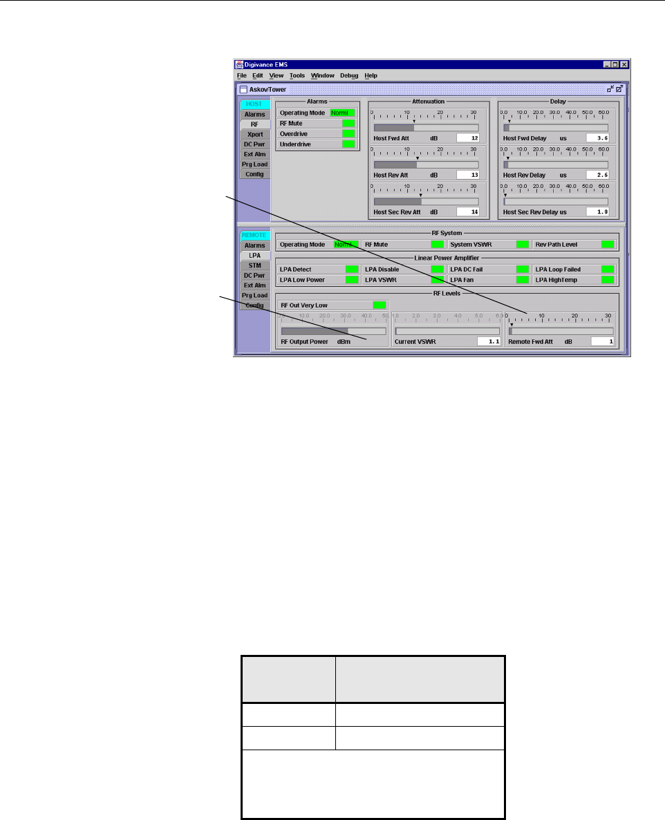
Figure 4-10. REMOTE LPA Display
2. Check the level of the RF output signal (as determined in Section 2.6) against the system
design plan specifications. Table 4-1 shows the output signal level required to provide 5
watts per channel for systems with 1 to 2 channels. The maximum output signal level
permitted for the system is 40.5 dBm (11 Watts).
3. Determine if more or less attenuation is required to produce the required output signal level.
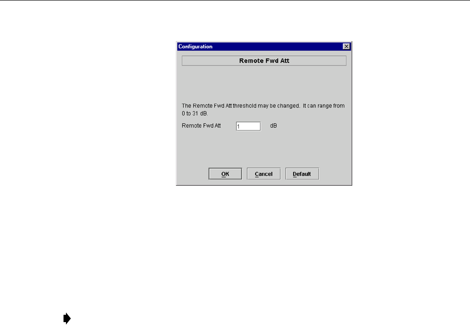
4. Right-click on the Remote Fwd Att section of the display (see Figure 4-10). The Remote
Fwd Att pop-up screen will open as shown in Figure 4-11.
5. Enter the required attenuation value and click OK to close the pop-up screen and to make
the changes take effect.
Table 4-1. Composite Output Signal Levels
NUMBER OF
CHANNELS
OUTPUT SIGNAL LEVEL
REQUIRED TO PROVIDE 5
WATTS PER CHANNEL
137 dBm
240 dBm
When there are three or more channels, each
channel will always be less than 5 watts since
the system has a maximum power output of
11 watts (40.5 dBm).
Right-click here to
open the Remote Fwd
Att pop-up screen
RF output signal level
ADCP-75-158 • Issue 1 • July 2003 • Section 4: Operation
Page 4-15
© 2003, ADC Telecommunications, Inc.
Figure 4-11. Remote Fwd Att Pop-Up Screen
6. Verify that the appropriate RF output signal level appears in the RF Pwr-VSWR Low
section (see Figure 4-10). This is primarily a reference value and should not take the place
of external test equipment when determining the power level of the composite RF output
signal. Depending on the modulation type and number of channels, the EMS software may
report a power level that is higher or lower than the actual RF output signal.
2.8 Enter Host Reverse Attenuation
The level of the RF signal that should be input to the BTS will vary depending on the type of
BTS, the receive distribution, and the number of channels present. To interface with the BTS,
the reverse path signal level must be adjusted to provide the signal level required by the BTS.
The HU provides from –1 dB of gain to +30 dB of gain in the reverse path. Use the following
procedure to set the reverse path gain:
1. Check the BTS manufacturer’s specifications to determine the composite signal level
required at the BTS reverse path input port.
2. Determine the overall gain and loss imposed on the signal by the antenna, antenna cable,
and by the cables that connect the HU to the BTS.
3. Determine the amount of gain required to raise the reverse path signal to the level required
at the BTS.
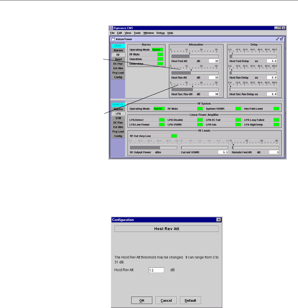
4. Click on the HOST RF tab. The HOST RF display will open within the EMS main
window as shown in Figure 4-12.
Note: To comply with Maximum Permissible Exposure (MPE) requirements, the
maximum composite output from the antenna cannot exceed 1000 Watts EIRP and the
antenna must be permanently installed in a fixed location that provides at least 6 meters
(20 feet) of separation from all persons.
ADCP-75-158 • Issue 1 • July 2003 • Section 4: Operation
Page 4-16
© 2003, ADC Telecommunications, Inc.
Figure 4-12. HOST RF Display
5. Right-click on the Host Rev Att section of the display (see Figure 4-12). The Host Rev
Att pop-up screen will open as shown in Figure 4-13.
Figure 4-13. Host Rev Att Pop-Up Screen
6. Enter the attenuation value that will provide the required gain. Refer to Table 4-2 for the
attenuation values and the corresponding gain (nominal) values.
7. Click OK to close the pop-up screen and to make the changes take effect.
Right-click here to
open the Host Rev Att
pop-up screen
Right-click here to
open the Host Div Rev
Att pop-up screen
ADCP-75-158 • Issue 1 • July 2003 • Section 4: Operation
Page 4-17
© 2003, ADC Telecommunications, Inc.
2.9 Enter Host Forward and Reverse Delay
The forward and reverse delay function allows entry of from 0 to 63 µsec of delay in the
forward and reverse paths. This feature is used when multiple systems are used to transport the
same channel and there is a significant difference in the path delay between systems. Additional
delay may be entered to balance the overall system delay. The amount of delay required must be
calculated by the RF engineer and should be included in the system design plan. The default
setting is 0 µsec. Use the following procedure to change the forward and reverse path delay:
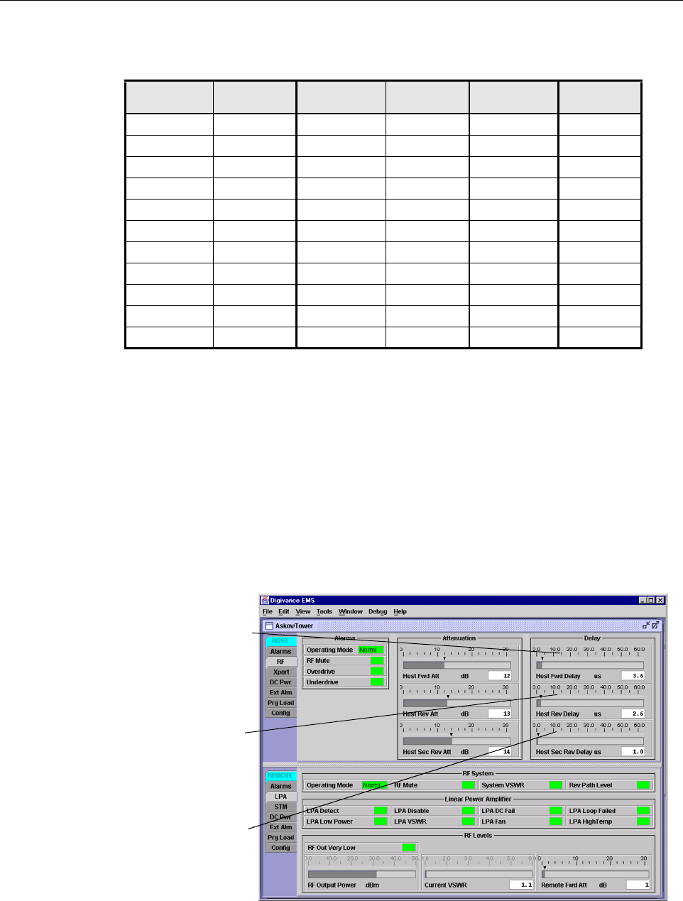
1. Click on the HOST RF tab. The HOST RF display will open within the EMS main
window as shown in Figure 4-14.
Figure 4-14. HOST RF Display
Table 4-2. Reverse Path Attenuation Settings and Nominal Gain Provided
ATTENUATION
SETTING
GAIN
PROVIDED
ATTENUATION
SETTING
GAIN
PROVIDED
ATTENUATION
SETTING
GAIN
PROVIDED
0 dB →30 dB 11 dB →19 dB 22 dB →8 dB
1 dB 29 dB 12 dB 18 dB 23 dB 7 dB
2 dB 28 dB 13 dB 17 dB 24 dB 6 dB
3 dB 27 dB 14 dB 16 dB 25 dB 5 dB
4 dB 26 dB 15 dB 15 dB 26 dB 4 dB
5 dB 25 dB 16 dB 14 dB 27 dB 3 dB
6 dB 24 dB 17 dB 13 dB 28 dB 2 dB
7 dB 23 dB 18 dB 12 dB 29 dB 1 dB
8 dB 22 dB 19 dB 11 dB 30 dB 0 dB
9 dB 21 dB 20 dB 10 dB 31 dB –1 dB
10 dB 20 dB 21 dB 9 dB -- --
Right-click here to
open the Host Fwd
Delay pop-up screen
Right-click here to
open the Host Rev
Delay pop-up screen
Right-click here to
open the Host Div Rev
Delay pop-up screen