ADC Telecommunications DLC1902B Digivance® LRCS 1900 MHz, 20-Watt LPA User Manual 75158
ADC Telecommunications Inc Digivance® LRCS 1900 MHz, 20-Watt LPA 75158
Contents
User manual 4
ADCP-75-158 • Issue 1 • July 2003 • Section 4: Operation
Page 4-4
© 2003, ADC Telecommunications, Inc.
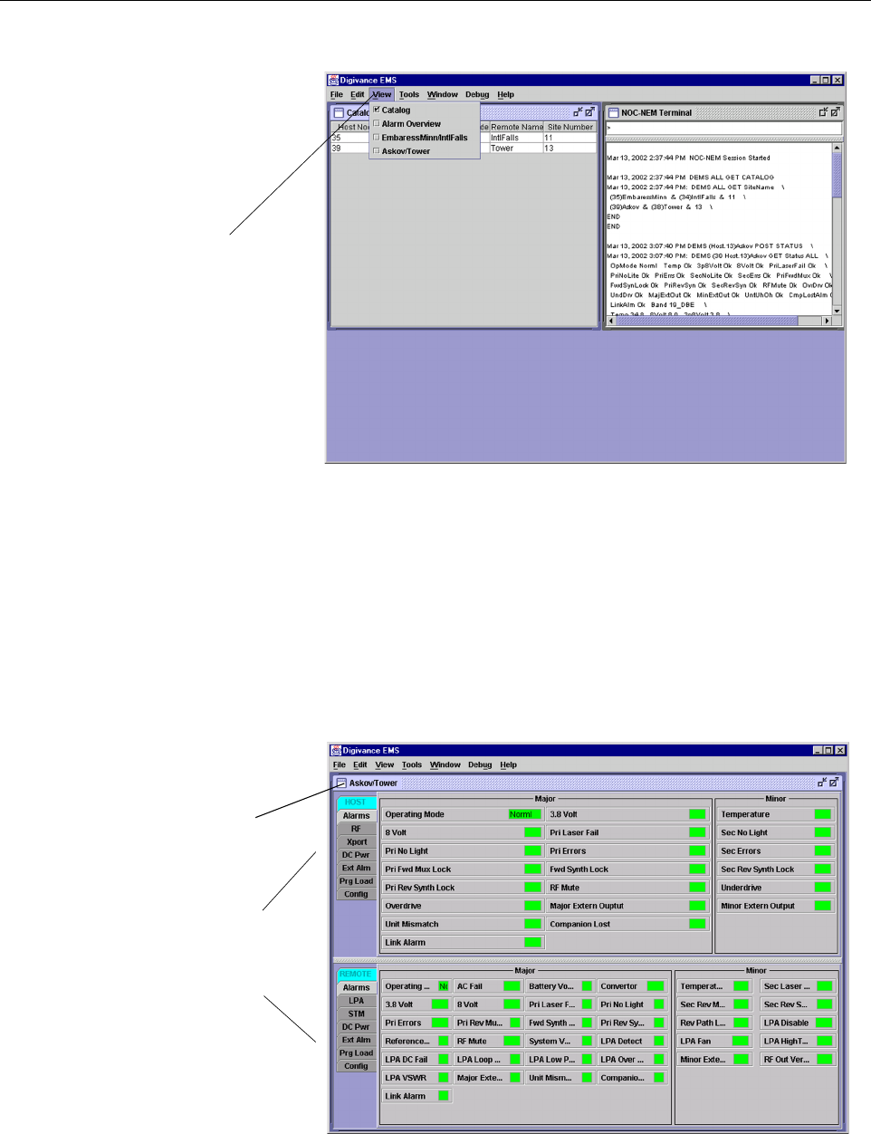
Figure 4-1. Digivance Element Management System Main Window
9. Open the View drop down menu and connect to the Host and Remote pair by selecting
“NotNamed/NotNamed”. The HOST Alarms display and the REMOTE Alarms display
will open within the main window as shown in Figure 4-2.
10. Verify that the Host and Remote Unit are loaded with the current system software and
download the current software to both the Host and the Remote unit if necessary. Refer to
Section 2.2 for details.
Figure 4-2. Selecting Display Tabs
Click to view drop
down menu
Clicking on the tabs in
this list will open the cor-
responding display.
Host/Remote pair
site name

ADCP-75-158 • Issue 1 • July 2003 • Section 4: Operation
Page 4-5
© 2003, ADC Telecommunications, Inc.
11. Click on the HOST Config tab and on the REMOTE Config tab (see Figure 4-2). The
HOST Config display and the REMOTE Config display will open within the main
window.
12. Enter the Site Name and Site Number for both the HOST and the REMOTE unit. Refer to
Section 2.4 for details.
13. If the site has multiple host units, reconnect the CAN cables to the HU’s NET IN and NET
OUT ports.
14. Verify that no Major (except Major Extern Alarm) or Minor alarms are being reported in
either the HOST or REMOTE Alarm displays and that all alarm fields (except Major
Extern Alarm) are green.
15. Click on the HOST RF tab (see Figure 4-2). The HOST RF display will open within the
main window.
16. Enter the Host Fwd Att (Forward Attenuation) values. This sets the forward input RF signal
level at the HU. Refer to Section 2.5 for details. By default, this value is set to 0 dB. If the
DRIVE LED on the HU front panel was red, it should turn green when this step is completed.
17. Determine if the RF output power at the STM ANTENNA is at the correct level per
channel up to a composite maximum of +40.5 dBm. Refer to Section 2.6 for details.
18. Place the MUTE/NORM/RESET switch (on LPA front panel) in the NORM position.
19. Verify that the STATUS indicator (on LPA front panel) turns from steady green to blinking
green.
20. Click on the REMOTE LPA tab (see Figure 4-2). The REMOTE PA display will open
within the main window.
21. Enter the Remote Fwd Att value. This adjusts the RF output signal level at the STM
ANTENNA port. Refer to Section 2.7 for details. By default this value is set to 0 dB.
22. Click on the HOST RF tab (see Figure 4-2). The HOST RF display will open within the
main window.
23. Enter the Host Rev Att (Reverse Attenuation). This sets the reverse output RF signal
levels at the HU. Refer to Section 2.8 for details.
24. If a delay adjustment is required per the system design plan, enter the Host Fwd Delay
and Host Rev Delay values. By default, the delay values are set to 0. Refer to Section 2.9
for details.
25. If a separate laptop computer loaded with the EMS software was used to initially
configure the system, disconnect the laptop computer from the SERVICE connector on the
HU front panel.
26. Reconnect the external alarm system or notify the alarm system provider that the turn-up
process has been completed.
Note: For continuous monitoring of alarms, each HU and RU pair must remain
permanently connected to a PC-type desktop computer loaded with the EMS software.
When two or more systems are connected together through the CAN interface, only one
EMS computer is required to manage the networked HU and RU systems. The EMS
computer may be connected to the SERVICE port on any one of the HUs in the network.
ADCP-75-158 • Issue 1 • July 2003 • Section 4: Operation
Page 4-6
© 2003, ADC Telecommunications, Inc.
2.2 Verify/Download HU and RU System Software
The HU’s and RU’s may require a system software download if they are not loaded with the
current system software. Use the following procedure to check the version number of the
system software and if necessary to download the current system software:
1. Click on the HOST Prg Load tab and on the REMOTE Prg Load tab. The HOST Prg
Load display and the Remote Prg Load display will open within the EMS main window
as shown in Figure 4-3.
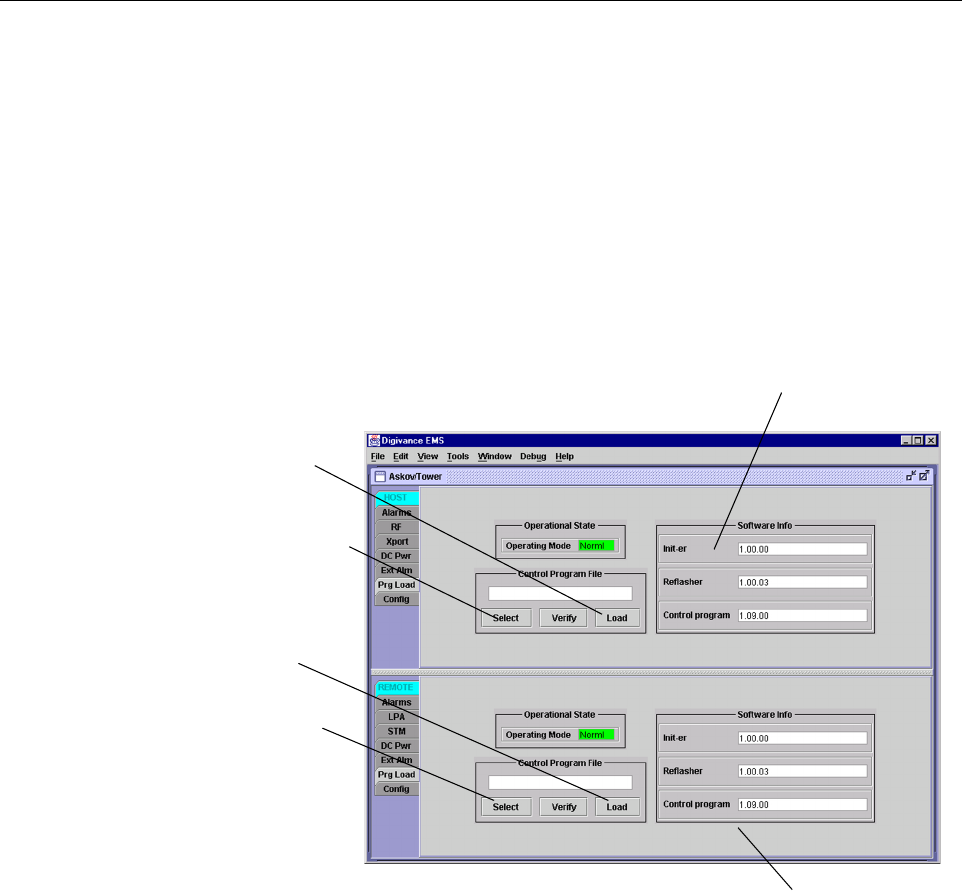
Figure 4-3. HOST and REMOTE Prg Load Displays
2. Click on the HOST Select button (see Figure 4-3). The Select Control Program File
window will open as shown in Figure 4-4. Browse until the folder where the Control
Program files are located is selected and the software files are displayed in the window.
3. Check the software version numbers shown in the Software Info section of the Prg Load
display against the version numbers of the software files displayed in the Select Control
Program File window. If files in the Select Control Program File window are a later
version than those shown in the Prg Load display, proceed with the software download. If
the version numbers shown in the Software Info section are the same as the version
numbers of the files in the Select Control Program File window, the software download
is not required.
Click to open Select Control
Program window for HOST
Click to start down-
load to HOST.
Click to start down-
load to REMOTE.
Click to open Select
Control Program win-
dow for REMOTE.
Verify software version
before starting download.
Verify software version
before starting download.